EP3480468A2 - Gegenläufiger schraubenkompressor mit versetztem schraubenrotor - Google Patents
Gegenläufiger schraubenkompressor mit versetztem schraubenrotor Download PDFInfo
- Publication number
- EP3480468A2 EP3480468A2 EP18203805.9A EP18203805A EP3480468A2 EP 3480468 A2 EP3480468 A2 EP 3480468A2 EP 18203805 A EP18203805 A EP 18203805A EP 3480468 A2 EP3480468 A2 EP 3480468A2
- Authority
- EP
- European Patent Office
- Prior art keywords
- rotor
- lobes
- another
- inwardly facing
- facing end
- Prior art date
- Legal status (The legal status is an assumption and is not a legal conclusion. Google has not performed a legal analysis and makes no representation as to the accuracy of the status listed.)
- Withdrawn
Links
- 239000012530 fluid Substances 0.000 claims abstract description 31
- 239000003507 refrigerant Substances 0.000 description 10
- 239000000314 lubricant Substances 0.000 description 4
- 230000009286 beneficial effect Effects 0.000 description 2
- 238000000034 method Methods 0.000 description 2
- 230000004075 alteration Effects 0.000 description 1
- 230000015572 biosynthetic process Effects 0.000 description 1
- 244000145845 chattering Species 0.000 description 1
- 238000001816 cooling Methods 0.000 description 1
- 230000008878 coupling Effects 0.000 description 1
- 238000010168 coupling process Methods 0.000 description 1
- 238000005859 coupling reaction Methods 0.000 description 1
- 238000006073 displacement reaction Methods 0.000 description 1
- 230000006698 induction Effects 0.000 description 1
- 230000010349 pulsation Effects 0.000 description 1
- 238000005096 rolling process Methods 0.000 description 1
- 238000006467 substitution reaction Methods 0.000 description 1
- 238000010792 warming Methods 0.000 description 1
Images


Classifications
-
- F—MECHANICAL ENGINEERING; LIGHTING; HEATING; WEAPONS; BLASTING
- F04—POSITIVE - DISPLACEMENT MACHINES FOR LIQUIDS; PUMPS FOR LIQUIDS OR ELASTIC FLUIDS
- F04C—ROTARY-PISTON, OR OSCILLATING-PISTON, POSITIVE-DISPLACEMENT MACHINES FOR LIQUIDS; ROTARY-PISTON, OR OSCILLATING-PISTON, POSITIVE-DISPLACEMENT PUMPS
- F04C18/00—Rotary-piston pumps specially adapted for elastic fluids
- F04C18/08—Rotary-piston pumps specially adapted for elastic fluids of intermeshing-engagement type, i.e. with engagement of co-operating members similar to that of toothed gearing
- F04C18/12—Rotary-piston pumps specially adapted for elastic fluids of intermeshing-engagement type, i.e. with engagement of co-operating members similar to that of toothed gearing of other than internal-axis type
- F04C18/14—Rotary-piston pumps specially adapted for elastic fluids of intermeshing-engagement type, i.e. with engagement of co-operating members similar to that of toothed gearing of other than internal-axis type with toothed rotary pistons
- F04C18/16—Rotary-piston pumps specially adapted for elastic fluids of intermeshing-engagement type, i.e. with engagement of co-operating members similar to that of toothed gearing of other than internal-axis type with toothed rotary pistons with helical teeth, e.g. chevron-shaped, screw type
-
- F—MECHANICAL ENGINEERING; LIGHTING; HEATING; WEAPONS; BLASTING
- F04—POSITIVE - DISPLACEMENT MACHINES FOR LIQUIDS; PUMPS FOR LIQUIDS OR ELASTIC FLUIDS
- F04C—ROTARY-PISTON, OR OSCILLATING-PISTON, POSITIVE-DISPLACEMENT MACHINES FOR LIQUIDS; ROTARY-PISTON, OR OSCILLATING-PISTON, POSITIVE-DISPLACEMENT PUMPS
- F04C18/00—Rotary-piston pumps specially adapted for elastic fluids
- F04C18/08—Rotary-piston pumps specially adapted for elastic fluids of intermeshing-engagement type, i.e. with engagement of co-operating members similar to that of toothed gearing
- F04C18/082—Details specially related to intermeshing engagement type pumps
- F04C18/084—Toothed wheels
-
- F—MECHANICAL ENGINEERING; LIGHTING; HEATING; WEAPONS; BLASTING
- F04—POSITIVE - DISPLACEMENT MACHINES FOR LIQUIDS; PUMPS FOR LIQUIDS OR ELASTIC FLUIDS
- F04C—ROTARY-PISTON, OR OSCILLATING-PISTON, POSITIVE-DISPLACEMENT MACHINES FOR LIQUIDS; ROTARY-PISTON, OR OSCILLATING-PISTON, POSITIVE-DISPLACEMENT PUMPS
- F04C2/00—Rotary-piston machines or pumps
- F04C2/08—Rotary-piston machines or pumps of intermeshing-engagement type, i.e. with engagement of co-operating members similar to that of toothed gearing
- F04C2/12—Rotary-piston machines or pumps of intermeshing-engagement type, i.e. with engagement of co-operating members similar to that of toothed gearing of other than internal-axis type
- F04C2/14—Rotary-piston machines or pumps of intermeshing-engagement type, i.e. with engagement of co-operating members similar to that of toothed gearing of other than internal-axis type with toothed rotary pistons
- F04C2/16—Rotary-piston machines or pumps of intermeshing-engagement type, i.e. with engagement of co-operating members similar to that of toothed gearing of other than internal-axis type with toothed rotary pistons with helical teeth, e.g. chevron-shaped, screw type
-
- F—MECHANICAL ENGINEERING; LIGHTING; HEATING; WEAPONS; BLASTING
- F04—POSITIVE - DISPLACEMENT MACHINES FOR LIQUIDS; PUMPS FOR LIQUIDS OR ELASTIC FLUIDS
- F04C—ROTARY-PISTON, OR OSCILLATING-PISTON, POSITIVE-DISPLACEMENT MACHINES FOR LIQUIDS; ROTARY-PISTON, OR OSCILLATING-PISTON, POSITIVE-DISPLACEMENT PUMPS
- F04C23/00—Combinations of two or more pumps, each being of rotary-piston or oscillating-piston type, specially adapted for elastic fluids; Pumping installations specially adapted for elastic fluids; Multi-stage pumps specially adapted for elastic fluids
- F04C23/001—Combinations of two or more pumps, each being of rotary-piston or oscillating-piston type, specially adapted for elastic fluids; Pumping installations specially adapted for elastic fluids; Multi-stage pumps specially adapted for elastic fluids of similar working principle
-
- F—MECHANICAL ENGINEERING; LIGHTING; HEATING; WEAPONS; BLASTING
- F04—POSITIVE - DISPLACEMENT MACHINES FOR LIQUIDS; PUMPS FOR LIQUIDS OR ELASTIC FLUIDS
- F04C—ROTARY-PISTON, OR OSCILLATING-PISTON, POSITIVE-DISPLACEMENT MACHINES FOR LIQUIDS; ROTARY-PISTON, OR OSCILLATING-PISTON, POSITIVE-DISPLACEMENT PUMPS
- F04C29/00—Component parts, details or accessories of pumps or pumping installations, not provided for in groups F04C18/00 - F04C28/00
- F04C29/0042—Driving elements, brakes, couplings, transmissions specially adapted for pumps
- F04C29/0078—Fixing rotors on shafts, e.g. by clamping together hub and shaft
-
- F—MECHANICAL ENGINEERING; LIGHTING; HEATING; WEAPONS; BLASTING
- F04—POSITIVE - DISPLACEMENT MACHINES FOR LIQUIDS; PUMPS FOR LIQUIDS OR ELASTIC FLUIDS
- F04C—ROTARY-PISTON, OR OSCILLATING-PISTON, POSITIVE-DISPLACEMENT MACHINES FOR LIQUIDS; ROTARY-PISTON, OR OSCILLATING-PISTON, POSITIVE-DISPLACEMENT PUMPS
- F04C29/00—Component parts, details or accessories of pumps or pumping installations, not provided for in groups F04C18/00 - F04C28/00
- F04C29/0042—Driving elements, brakes, couplings, transmissions specially adapted for pumps
- F04C29/0085—Prime movers
-
- F—MECHANICAL ENGINEERING; LIGHTING; HEATING; WEAPONS; BLASTING
- F04—POSITIVE - DISPLACEMENT MACHINES FOR LIQUIDS; PUMPS FOR LIQUIDS OR ELASTIC FLUIDS
- F04C—ROTARY-PISTON, OR OSCILLATING-PISTON, POSITIVE-DISPLACEMENT MACHINES FOR LIQUIDS; ROTARY-PISTON, OR OSCILLATING-PISTON, POSITIVE-DISPLACEMENT PUMPS
- F04C2240/00—Components
- F04C2240/20—Rotors
Definitions
- the subject matter disclosed herein relates generally to fluid machines, and more specifically, to fluid machines, such as compressors, having helically lobed rotors.
- Non-flammable, low GWP refrigerants are replacing existing refrigerants in many applications, but have lower density and do not possess the same cooling capacity as existing refrigerants.
- Replacement refrigerants require a compressor capable of providing a significantly greater displacement, such as a screw compressor.
- a rotor for use in a fluid machine includes a rotor shaft, a first portion supported by the rotor shaft and having a plurality of first lobes, and a second portion supported by the rotor shaft having a plurality of second lobes.
- the plurality of first lobes at an inwardly facing end of the first portion is arranged at a stagger angle relative to the plurality of second lobes at an inwardly facing end of the second portion.
- the stagger angle is greater than zero.
- the stagger angle is less than an angular pitch of the plurality of first lobes.
- the stagger angle is equal to between 10% and 90% of the angular pitch.
- the stagger angle is equal to between 25% and 75% of the angular pitch.
- each of the plurality of first lobes has a first lobe shape at the inwardly facing end of the first portion and each of the plurality of second lobes has a second lobe shape at the inwardly facing end of the second portion.
- the first lobe shape and the second lobe shape are substantially identical.
- first portion and the second portion are fixed for rotation with the rotor shaft.
- first portion and the second portion are rotatable about the rotor shaft.
- the first portion is rotatable independently from the second portion.
- the fluid machine further comprises another rotor including: another rotor shaft, another first portion supported by the another rotor shaft and having a plurality of first lobes; another second portion supported by the another rotor shaft having a plurality of second lobes.
- the plurality of first lobes at an inwardly facing end of the another first portion are arranged at another stagger angle relative to the plurality of second lobes at an inwardly facing end of the another second portion.
- the another stagger angle is greater than zero.
- the stagger angle and the another stagger angle are different.
- a rotor for use in a fluid machine includes a rotor shaft, a first portion supported by the rotor shaft and having a plurality of first lobes, and a second portion supported by the rotor shaft having a plurality of second lobes.
- the plurality of first lobes at an inwardly facing end of the first portion aligned is with the plurality of second lobes at an inwardly facing end of the second portion.
- an angle formed between the plurality of first lobes at the inwardly facing end of the first portion and the plurality of second lobes at an inwardly facing end of the second portion within 5% of an angular pitch of the plurality of first lobes.
- the angle is zero degrees.
- each of the plurality of first lobes has a first lobe shape at the inwardly facing end of the first portion and each of the plurality of second lobes has a second lobe shape at the inwardly facing end of the second portion.
- the first lobe shape and the second lobe shape are substantially identical.
- first portion and the second portion are fixed for rotation with the rotor shaft.
- first portion and the second portion are rotatable about the rotor shaft.
- the first portion is rotatable independently from the second portion.
- the fluid machine further comprises another rotor including: another rotor shaft, another first portion supported by the another rotor shaft and having a plurality of first lobes, and another second portion supported by the another rotor shaft having a plurality of second lobes.
- the plurality of first lobes at an inwardly facing end of the another first portion are aligned with the plurality of second lobes at an inwardly facing end of the another second portion.
- a first angle formed between the plurality of first lobes at the inwardly facing end of the first portion and the plurality of second lobes at an inwardly facing end of the second portion is equal to a second angle of formed between the plurality of first lobes at the inwardly facing end of the another first portion and the plurality of second lobes at an inwardly facing end of the another second portion.
- the fluid machine 20 is an opposed screw compressor.
- a fluid machine such as a pump, fluid motor, or engine for example.
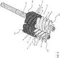
- the fluid machine 20 includes a first rotor 22 intermeshed with a second rotor 24.
- the first rotor 22 is a male rotor having a male-lobed working portion 26 and the second rotor 24 is a female rotor including a female-lobed portion 28.
- the first rotor 22 may be a female rotor and the second rotor 24 may be a male rotor.
- the working portion 26 of the first rotor 22 includes at least one first helical lobe 30 and at least one second helical lobe 32.
- the first rotor 22 includes two separate portions 34, 36 defining the first helical lobes 30 and the second helical lobes 32, respectively.
- the fluid machine 20 includes a first shaft 38 fixed for rotation with the first rotor 22.
- the fluid machine 20 further include a casing 40 rotatably supporting the first shaft 38 and at least partially enclosing the first rotor 22 and the second rotor 24.
- a first end 42 and a second end 44 of the casing 40 are configured to rotatably support the first shaft 38.
- the first shaft 38 of the illustrated embodiments is directly coupled to an electric motor 46 operable to drive rotation of the first shaft 38 about an axis X.
- Any suitable type of electric motor 46 is contemplated herein, including but not limited to an induction motor, permanent magnet (PM) motor, and switch reluctance motor for example.
- the first rotor 22 is fixed to the first shaft 38 by a fastener, coupling, integral formation, interference fit, and /or any additional structures or methods known to a person having ordinary skill in the art (not shown), such that the first rotor 22 and the first shaft 38 rotate about axis X in unison.
- the fluid machine 20 additionally includes a second shaft 48 operable to rotationally support the second rotor 24.
- the second rotor 24 includes an axially extending bore 50 within which the second shaft 48 is received.
- the second shaft 48 is stationary or fixed relative to the casing 40 and the second rotor 24 is configured to rotate about the second shaft 48.
- embodiments where the second shaft 48 is also rotatable relative to the casing 40 are also contemplated herein.
- the first rotor 22 is shown as including a first portion 34 having four first helical lobes 30 and a second portion 36 having four second helical lobes 32.
- the illustrated, non-limiting embodiment is intended as an example only, and it should be understood by a person of ordinary skill in the art that any suitable number of first helical lobes 30 and second helical lobes 32 are within the scope of the disclosure.
- the first helical lobes 30 and the second helical lobes 32 have opposite helical configurations.
- the first helical lobes 30 are left-handed and the second helical lobes 32 are right-handed.
- the first helical lobes 30 may be right-handed and the second helical lobes 32 may be left-handed.
- the second rotor 24 has a first portion 52 configured to mesh with the first helical lobes 30 and a second portion 54 configured to mesh with the second helical lobes 32.
- each portion 52, 54 of the second rotor 24 includes one or more lobes having an opposite configuration to the corresponding helical lobes 30, 32 of the first rotor 22.
- the first portion 52 of the second rotor 24 has at least one right-handed lobe 56
- the second portion 54 of the second rotor 24 includes at least one left-handed lobe 58.
- first portion 52 of the second rotor 24 is configured to rotate independently from the second portion 54 of the second rotor 24.
- first and second portions 52, 54 are rotationally coupled are also contemplated herein.
- Each portion 52, 54 of the second rotor 24 may include any number of lobes 56, 58.
- the total number of lobes 56, 58 formed in each portion 52, 54 of the second rotor 24 is generally larger than a corresponding portion, 34 and 36, respectively, of the first rotor 22.
- the first portion 54 of the second rotor 24 configured to intermesh with the first helical lobes 30 may include five helical lobes 56.
- embodiments where the total number of lobes 56, 58 in a portion 52, 54 of the second rotor 24 is equal to a corresponding group of helical lobes (i.e. the first helical lobes 30 or the second helical lobes 32) of the first rotor 22 are also within the scope of the disclosure.
- the fluid machine 20 may include a first shaft passage 57 extending axially through the first shaft 38 and a second shaft passage 59 extending axially through a portion of the second shaft 48.
- the first shaft passage 57 and/or the second shaft passage 59 communicate lubricant from a sump 61, through first shaft 38 and/or second shaft 48, out one or more radial passages (not shown), and along one or more surfaces of the first rotor 22 and/or the second rotor 24.
- the fluid machine 20 further includes an axially-extending passage (not shown) defined between the second shaft 48 and the bore 50 formed in the second rotor 24. The passage is configured to allow lubricant to pass or circulate there through.
- relatively high pressure discharge at first and second ends 42, 44 of the casing 40, the first rotor 22, and the second rotor 24 and relatively low pressure suction at a central location of the first rotor 22 and the second rotor 24 urge lubricant through each of the passages.
- the circulation of lubricant through the passage disposed between bore 50 and the second shaft 48 provides internal bearing surfaces between each of the first and second portions 52, 54 and the second shaft 48 to reduce friction there between and further allow the first portion 52 of the second rotor 24 to rotate independently of the second portion 54 of the second rotor 24.
- a gas or other fluid such as a low GWP refrigerant for example, is drawn to a central location by a suction process generated by the fluid machine 20.
- Rotation of the first rotor 22 and the second rotor 24 compresses the refrigerant and forces the refrigerant toward first and second ends 42, 44 of the casing 40 between the sealed surfaces of the meshed rotors 22, 24 due to the structure and function of the opposing helical rotors 22, 24.
- the compressed refrigerant is routed by an internal gas passage within the casing 40 and discharged through the second end 44 of the casing 40.
- the discharged refrigerant passes through the electric motor 46 and out of a discharge passage 64.
- Each portion 34, 36 of the first rotor 22, and each portion 52, 54 of the second rotor 24 has a first end 60 (shown as 60a-60d), for example arranged adjacent a surface of the casing 40, and a second end 62, facing a corresponding portion of the rotor 22, 24.
- the second end of each portion 34, 36, 52, 54 has a generally planar surface, such as extending substantially perpendicular to the rotational axis of the corresponding rotor 22, 24 for example.
- the second end of a portion 34, 36, 52, 54 includes a cross-section of each of the plurality of lobes included in that portion 34, 36, 52, 54.
- the cross-section of each lobe 30, 32, 56, 58 defines a lobe shape.
- the lobe shapes for each of the plurality of lobes 30, 32, 56, 58 within a portion 34, 36, 52, 54 may be substantially identical, as shown in the illustrated, non-limiting embodiment, or alternatively, may vary.
- the lobe shapes defined at the second end 62a of the first portion 34 of the first rotor 22 may be substantially identical to the lobe shapes defined at an adjacent second end 62b of the second portion 36 of the first rotor 22.
- the lobe shapes defined at a second end 62c of the first portion 52 of the second rotor 24 may be substantially identical to the lobe shapes defined at an adjacent second end 62d of the second portion 54 of the second rotor 24.
- the first portion 34 and the second portion 36 of the first rotor 22 are arranged such that the ends of the lobes 30 at the second end 62a of the first portion 34 are substantially aligned with the ends of the lobes 32 at the second end 62b of the second portion 36. Accordingly, each of the lobe shapes of the second portion 36 is substantially aligned with a corresponding lobe shape of the first portion 34. Because the lobe shapes of the first portion 34 and the second portion 36 are identical in the embodiment of FIG. 4 , only the lobe shapes of the second portion 36 are visible.
- the lobes at the second ends 62 of the first portion 34 and the second portion 36 of a rotor are substantially aligned
- the lobes at the second ends 62 of the first and second portion 52, 54 of the other rotor, for example the second rotor 24 may, but need not be aligned.
- the lobe ends of the first and second portion 52, 54 are arranged such that the lobe shapes formed at the first end 62c of the first portion 52 of the second rotor 24 are substantially aligned with the lobe shapes formed at the adjacent second end 62d of the second portion 54 of the second rotor 24.
- an axial force balance may be achieved thereby minimizing or eliminating chattering of the rotors 22, 24.
- Embodiments where at least one of the rotors 22, 24 has an aligned configuration may be particularly beneficial in a fluid machine 20 having a small tonnage.
- first portion 34, 52 and the second portion 36, 54 of at least one of the first rotor 22 and the second rotor 24, respectively are arranged in a staggered configuration.
- first portion 34 and the second portion 36 of the first rotor 22 are arranged such that the ends of the lobes 30 at the second end 62a of the first portion 34 are rotated relative to the ends of the lobes 32 at the second end 62b of the second portion 36. Accordingly, each of the lobe shapes of the second portion 36 is rotated relative to a corresponding lobe shape of the first portion 34.
- first and second portion 52, 54 may be arranged such that the lobe shapes formed at the first end 62c of the first portion 52 of the second rotor 24 are rotated relative to the lobe shapes formed at the adjacent second end 62d of the second portion 54 of the second rotor 24.
- first rotor 22 and the second rotor 24 are illustrated as having a staggered configuration, embodiments where only one of the first and second rotor 22, 24 has a staggered configuration are also contemplated herein.
- the lobes at the end 62b, 62d of the second portion 36, 54 are arranged at an angle relative to the lobes at the end 62a, 62c of the first portion 34, 52 of a rotor 22, 24.
- the angle of the stagger S is measured between a radius of a lobe 30, 56 of the first portion 34, 52 and a radius of an adjacent lobe 32, 58 of the corresponding second portion 36, 54.
- the degree of the angle of stagger S must be greater than zero and less than the angular pitch, P, of lobes 30, 56 at the end 62a, 62c of the first portion 34, 52.
- the angular pitch P of the lobes 30, 56 on the first portion 34, 52 of a rotor 22, 24 is calculated by dividing 360° by the total number of lobes 30, 56 of the portion 34, 52.
- the angular pitch P of the first portion 34 of the first rotor 22 is 90°.
- the stagger angle S is greater than 0° and less than 90°.
- the staggered angle S is between about 10% and about 90% of the angular pitch, and more specifically between about 25% and about 75% of the angular pitch P.
- any suitable staggered angle S is contemplated herein.
- the angle of stagger S is equal to zero, or in some embodiments, the angle of stagger S is within 5% of the angular pitch P.
Landscapes
- Engineering & Computer Science (AREA)
- Mechanical Engineering (AREA)
- General Engineering & Computer Science (AREA)
- Applications Or Details Of Rotary Compressors (AREA)
- Structures Of Non-Positive Displacement Pumps (AREA)
Applications Claiming Priority (1)
| Application Number | Priority Date | Filing Date | Title |
|---|---|---|---|
| US201762580719P | 2017-11-02 | 2017-11-02 |
Publications (2)
| Publication Number | Publication Date |
|---|---|
| EP3480468A2 true EP3480468A2 (de) | 2019-05-08 |
| EP3480468A3 EP3480468A3 (de) | 2019-08-21 |
Family
ID=64048976
Family Applications (1)
| Application Number | Title | Priority Date | Filing Date |
|---|---|---|---|
| EP18203805.9A Withdrawn EP3480468A3 (de) | 2017-11-02 | 2018-10-31 | Gegenläufiger schraubenkompressor mit versetztem schraubenrotor |
Country Status (3)
| Country | Link |
|---|---|
| US (1) | US20190128261A1 (de) |
| EP (1) | EP3480468A3 (de) |
| CN (1) | CN109751241A (de) |
Cited By (1)
| Publication number | Priority date | Publication date | Assignee | Title |
|---|---|---|---|---|
| EP4239198A4 (de) * | 2021-02-26 | 2024-05-22 | Gree Electric Appliances, Inc. of Zhuhai | Rotoranordnung, verdichter und klimaanlage |
Families Citing this family (2)
| Publication number | Priority date | Publication date | Assignee | Title |
|---|---|---|---|---|
| CN112780560A (zh) * | 2021-02-26 | 2021-05-11 | 珠海格力电器股份有限公司 | 一种转子组件、压缩机及空调机 |
| CN112797001B (zh) * | 2021-02-26 | 2024-11-15 | 珠海格力电器股份有限公司 | 转子组件、压缩机及空调 |
Family Cites Families (9)
| Publication number | Priority date | Publication date | Assignee | Title |
|---|---|---|---|---|
| FR894018A (fr) * | 1942-05-21 | 1944-12-12 | Pompe à vide ou à gaz, constituée par deux ou plus de deux vis s'engageant les unes dans les autres | |
| US2714857A (en) * | 1951-09-04 | 1955-08-09 | Roper Corp Geo D | Gear pump |
| US3557687A (en) * | 1968-08-16 | 1971-01-26 | Boris Lazarevich Grinpress | Screw compressor |
| DE3031801C2 (de) * | 1980-08-22 | 1981-11-19 | Aerzener Maschinenfabrik Gmbh, 3251 Aerzen | Schraubenverdichter |
| JPH05272478A (ja) * | 1992-01-31 | 1993-10-19 | Matsushita Electric Ind Co Ltd | 真空ポンプ |
| JP2002206493A (ja) * | 2000-11-10 | 2002-07-26 | Ebara Corp | スクリュー式ドライ真空ポンプ |
| EP1687540A1 (de) * | 2003-11-10 | 2006-08-09 | The BOC Group plc | Verbesserungen bei trockenpumpen |
| CN202140315U (zh) * | 2011-06-13 | 2012-02-08 | 浙江佳力科技股份有限公司 | 分段式变螺距转子结构 |
| US9470228B2 (en) * | 2012-07-03 | 2016-10-18 | Brian J. O'Connor | Multiple segment lobe pump |
-
2018
- 2018-10-29 US US16/173,915 patent/US20190128261A1/en not_active Abandoned
- 2018-10-31 EP EP18203805.9A patent/EP3480468A3/de not_active Withdrawn
- 2018-11-01 CN CN201811294805.6A patent/CN109751241A/zh active Pending
Non-Patent Citations (1)
| Title |
|---|
| None |
Cited By (2)
| Publication number | Priority date | Publication date | Assignee | Title |
|---|---|---|---|---|
| EP4239198A4 (de) * | 2021-02-26 | 2024-05-22 | Gree Electric Appliances, Inc. of Zhuhai | Rotoranordnung, verdichter und klimaanlage |
| US12305641B2 (en) | 2021-02-26 | 2025-05-20 | Gree Electric Appliances, Inc. Of Zhuhai | Rotor assembly, compressor and air conditioner |
Also Published As
| Publication number | Publication date |
|---|---|
| US20190128261A1 (en) | 2019-05-02 |
| CN109751241A (zh) | 2019-05-14 |
| EP3480468A3 (de) | 2019-08-21 |
Similar Documents
| Publication | Publication Date | Title |
|---|---|---|
| US11149732B2 (en) | Opposed screw compressor having non-interference system | |
| US11268512B2 (en) | Fluid machine with helically lobed rotors | |
| EP3701151B1 (de) | Schmiermittelzufuhrkanal für kompressorhintergrund | |
| EP3480468A2 (de) | Gegenläufiger schraubenkompressor mit versetztem schraubenrotor | |
| JP6108967B2 (ja) | 回転型圧縮機構 | |
| EP0933532A2 (de) | Drehkolbenflügelzellenmaschine | |
| US11365735B2 (en) | Internal discharge gas passage for compressor | |
| US11466687B2 (en) | Rotary compressor and refrigeration cycle apparatus | |
| JPH10259701A (ja) | 容積型流体機械 | |
| EP3784907B1 (de) | Schraubenverdichter mit aussenmotorrotor | |
| EP3555477B1 (de) | Schraubenverdichter mit einem magnetgetriebe | |
| US6589026B2 (en) | Fluid machinery having a helical mechanism with through holes for ventilation | |
| WO2025052980A1 (ja) | スクリュ圧縮機及びガス圧縮設備 | |
| WO2025052981A1 (ja) | スクリュ圧縮機及びガス圧縮設備 | |
| KR20080028173A (ko) | 공기 압축기 |
Legal Events
| Date | Code | Title | Description |
|---|---|---|---|
| PUAI | Public reference made under article 153(3) epc to a published international application that has entered the european phase |
Free format text: ORIGINAL CODE: 0009012 |
|
| STAA | Information on the status of an ep patent application or granted ep patent |
Free format text: STATUS: THE APPLICATION HAS BEEN PUBLISHED |
|
| AK | Designated contracting states |
Kind code of ref document: A2 Designated state(s): AL AT BE BG CH CY CZ DE DK EE ES FI FR GB GR HR HU IE IS IT LI LT LU LV MC MK MT NL NO PL PT RO RS SE SI SK SM TR |
|
| AX | Request for extension of the european patent |
Extension state: BA ME |
|
| PUAL | Search report despatched |
Free format text: ORIGINAL CODE: 0009013 |
|
| AK | Designated contracting states |
Kind code of ref document: A3 Designated state(s): AL AT BE BG CH CY CZ DE DK EE ES FI FR GB GR HR HU IE IS IT LI LT LU LV MC MK MT NL NO PL PT RO RS SE SI SK SM TR |
|
| AX | Request for extension of the european patent |
Extension state: BA ME |
|
| RIC1 | Information provided on ipc code assigned before grant |
Ipc: F04C 18/16 20060101AFI20190715BHEP Ipc: F04C 23/00 20060101ALI20190715BHEP |
|
| STAA | Information on the status of an ep patent application or granted ep patent |
Free format text: STATUS: REQUEST FOR EXAMINATION WAS MADE |
|
| 17P | Request for examination filed |
Effective date: 20200219 |
|
| RBV | Designated contracting states (corrected) |
Designated state(s): AL AT BE BG CH CY CZ DE DK EE ES FI FR GB GR HR HU IE IS IT LI LT LU LV MC MK MT NL NO PL PT RO RS SE SI SK SM TR |
|
| STAA | Information on the status of an ep patent application or granted ep patent |
Free format text: STATUS: EXAMINATION IS IN PROGRESS |
|
| 17Q | First examination report despatched |
Effective date: 20220307 |
|
| STAA | Information on the status of an ep patent application or granted ep patent |
Free format text: STATUS: THE APPLICATION HAS BEEN WITHDRAWN |
|
| 18W | Application withdrawn |
Effective date: 20221005 |