EP3701150B1 - Internal discharge gas passage for compressor - Google Patents
Internal discharge gas passage for compressor Download PDFInfo
- Publication number
- EP3701150B1 EP3701150B1 EP18800412.1A EP18800412A EP3701150B1 EP 3701150 B1 EP3701150 B1 EP 3701150B1 EP 18800412 A EP18800412 A EP 18800412A EP 3701150 B1 EP3701150 B1 EP 3701150B1
- Authority
- EP
- European Patent Office
- Prior art keywords
- bearing housing
- rotor
- recess
- casing
- compressor casing
- Prior art date
- Legal status (The legal status is an assumption and is not a legal conclusion. Google has not performed a legal analysis and makes no representation as to the accuracy of the status listed.)
- Active
Links
- 239000012530 fluid Substances 0.000 claims description 33
- 239000003507 refrigerant Substances 0.000 claims description 23
- 230000008878 coupling Effects 0.000 claims description 4
- 238000010168 coupling process Methods 0.000 claims description 4
- 238000005859 coupling reaction Methods 0.000 claims description 4
- 238000004891 communication Methods 0.000 claims description 3
- 239000000314 lubricant Substances 0.000 description 4
- 230000008901 benefit Effects 0.000 description 3
- 238000001816 cooling Methods 0.000 description 3
- 239000000446 fuel Substances 0.000 description 3
- 230000007246 mechanism Effects 0.000 description 3
- XLYOFNOQVPJJNP-UHFFFAOYSA-N water Substances O XLYOFNOQVPJJNP-UHFFFAOYSA-N 0.000 description 3
- 238000000034 method Methods 0.000 description 2
- 230000004075 alteration Effects 0.000 description 1
- 230000015572 biosynthetic process Effects 0.000 description 1
- 230000006835 compression Effects 0.000 description 1
- 238000007906 compression Methods 0.000 description 1
- 238000006073 displacement reaction Methods 0.000 description 1
- 230000006698 induction Effects 0.000 description 1
- 238000002347 injection Methods 0.000 description 1
- 239000007924 injection Substances 0.000 description 1
- 230000008569 process Effects 0.000 description 1
- 238000005096 rolling process Methods 0.000 description 1
- 238000006467 substitution reaction Methods 0.000 description 1
- 238000010792 warming Methods 0.000 description 1
Images


Classifications
-
- F—MECHANICAL ENGINEERING; LIGHTING; HEATING; WEAPONS; BLASTING
- F04—POSITIVE - DISPLACEMENT MACHINES FOR LIQUIDS; PUMPS FOR LIQUIDS OR ELASTIC FLUIDS
- F04C—ROTARY-PISTON, OR OSCILLATING-PISTON, POSITIVE-DISPLACEMENT MACHINES FOR LIQUIDS; ROTARY-PISTON, OR OSCILLATING-PISTON, POSITIVE-DISPLACEMENT PUMPS
- F04C18/00—Rotary-piston pumps specially adapted for elastic fluids
- F04C18/08—Rotary-piston pumps specially adapted for elastic fluids of intermeshing-engagement type, i.e. with engagement of co-operating members similar to that of toothed gearing
- F04C18/12—Rotary-piston pumps specially adapted for elastic fluids of intermeshing-engagement type, i.e. with engagement of co-operating members similar to that of toothed gearing of other than internal-axis type
- F04C18/14—Rotary-piston pumps specially adapted for elastic fluids of intermeshing-engagement type, i.e. with engagement of co-operating members similar to that of toothed gearing of other than internal-axis type with toothed rotary pistons
- F04C18/16—Rotary-piston pumps specially adapted for elastic fluids of intermeshing-engagement type, i.e. with engagement of co-operating members similar to that of toothed gearing of other than internal-axis type with toothed rotary pistons with helical teeth, e.g. chevron-shaped, screw type
-
- F—MECHANICAL ENGINEERING; LIGHTING; HEATING; WEAPONS; BLASTING
- F04—POSITIVE - DISPLACEMENT MACHINES FOR LIQUIDS; PUMPS FOR LIQUIDS OR ELASTIC FLUIDS
- F04C—ROTARY-PISTON, OR OSCILLATING-PISTON, POSITIVE-DISPLACEMENT MACHINES FOR LIQUIDS; ROTARY-PISTON, OR OSCILLATING-PISTON, POSITIVE-DISPLACEMENT PUMPS
- F04C29/00—Component parts, details or accessories of pumps or pumping installations, not provided for in groups F04C18/00 - F04C28/00
- F04C29/12—Arrangements for admission or discharge of the working fluid, e.g. constructional features of the inlet or outlet
-
- F—MECHANICAL ENGINEERING; LIGHTING; HEATING; WEAPONS; BLASTING
- F04—POSITIVE - DISPLACEMENT MACHINES FOR LIQUIDS; PUMPS FOR LIQUIDS OR ELASTIC FLUIDS
- F04C—ROTARY-PISTON, OR OSCILLATING-PISTON, POSITIVE-DISPLACEMENT MACHINES FOR LIQUIDS; ROTARY-PISTON, OR OSCILLATING-PISTON, POSITIVE-DISPLACEMENT PUMPS
- F04C2210/00—Fluid
- F04C2210/22—Fluid gaseous, i.e. compressible
-
- F—MECHANICAL ENGINEERING; LIGHTING; HEATING; WEAPONS; BLASTING
- F04—POSITIVE - DISPLACEMENT MACHINES FOR LIQUIDS; PUMPS FOR LIQUIDS OR ELASTIC FLUIDS
- F04C—ROTARY-PISTON, OR OSCILLATING-PISTON, POSITIVE-DISPLACEMENT MACHINES FOR LIQUIDS; ROTARY-PISTON, OR OSCILLATING-PISTON, POSITIVE-DISPLACEMENT PUMPS
- F04C29/00—Component parts, details or accessories of pumps or pumping installations, not provided for in groups F04C18/00 - F04C28/00
- F04C29/06—Silencing
- F04C29/068—Silencing the silencing means being arranged inside the pump housing
Description
- The subject matter disclosed herein relates generally to fluid machines, and more specifically, to fluid machines, such as compressors, having helically lobed rotors.
- It has been determined that commonly used refrigerants, such as R-410A in one non-limiting example, have unacceptable global warming potential (GWP) such that their use will cease for many HVAC&R applications. Non-flammable, low GWP refrigerants are replacing existing refrigerants in many applications, but have lower density and do not possess the same cooling capacity as existing refrigerants. Replacement refrigerants require a compressor capable of providing a significantly greater displacement, such as a screw compressor.
- Existing screw compressors typically utilize roller, ball, or other rolling element bearings to precisely position the rotors and minimize friction during high speed operation. However, for typical HVAC&R applications, existing screw compressors with roller element bearings result in an unacceptably large and costly fluid machine.
- Therefore, there exists a need in the art for an appropriately sized and cost effective fluid machine that minimizes friction while allowing precise positioning and alignment of the rotors.
-
WO 2010/008457 A2 relates to screw compressors with means for varying volume ratio. -
US 4609329 A discloses a variable volume ratio screw compressor having a side load inlet port for the injection of refrigerant vapor into the interlobe volume. -
US 2012/039737 A1 discloses a screw compressor having an overpressure outlet and overpressure valve provided in a side wall of a casing of the compressor. -
EP 0828079 A2 relates to a casing structure for a Lysholm compressor which is adapted to accommodate intermeshing male and female rotors. -
US 2004/041280 A1 discloses an air supply system for a fuel cell, comprising an air supply mechanism adapted to supply air to a fuel cell and a liquefaction unit acting as a water supply mechanism for separating water from exhaust gas discharged from the fuel cell and supplying that water to the air supply mechanism. - According to a first aspect of the present invention, a compressor casing having an internal gas passage includes a first bearing housing arranged at a first end of the casing, a second bearing housing arranged at a second, opposite end of the casing, and a rotor case disposed between the first bearing housing and the second bearing housing. The rotor case includes an axially extending bore within which a plurality of rotors is receivable and a hollow internal cavity separate from the bore. The hollow internal cavity is fluidly coupled to the bore via at least one recess. At least one exit opening is formed in the second bearing housing. The at least one exit opening is operably coupled to the hollow internal cavity of the rotor case. The second bearing housing comprises an internal chamber arranged in fluid communication with the hollow internal cavity of the rotor case, and the second bearing housing comprises a fluid passageway extending between the hollow internal cavity and the internal chamber.
- At least one of the first bearing housing and the second bearing housing may include the at least one recess fluidly coupling the bore to the hollow internal cavity.
- The first bearing housing may include a first recess and the second bearing housing may include a second recess.
- The at least one recess may be formed in the rotor case.
- The at least one exit opening may include a plurality of exit openings.
- Each of the plurality of exit openings may have a substantially identical configuration.
- The plurality of exit openings may be distributed about a periphery of the second bearing housing.
- The plurality of exit openings may be arranged about the second bearing housing such that compressed refrigerant output from the plurality of exit openings is uniformly distributed.
- The at least one exit opening may include a plurality of exit openings and the internal chamber distributes compressed refrigerant from the hollow internal cavity to each of the plurality of exit openings.
- The subject matter, which is regarded as the disclosure, is particularly pointed out and distinctly claimed in the claims at the conclusion of the specification. The foregoing and other features, and advantages of the disclosure are apparent from the following detailed description taken in conjunction with the accompanying drawings in which:
-
FIG. 1 is cross-sectional view of a fluid machine; -
FIG. 2 is a perspective view of a fluid machine; -
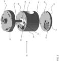
FIG. 3 is an exploded perspective view of a casing of a fluid a machine according to an embodiment; -
FIG. 4 is a top view of a rotor case according to an embodiment; -
FIG. 5 is a top view of a lower bearing housing according to an embodiment; -
FIG. 6A is a perspective view of an upper bearing housing according to an embodiment; -
FIG. 6B is another perspective view of an upper bearing housing according to an embodiment; -
FIG. 7 is a cross-sectional view of a casing of a fluid machine according to an embodiment; and -
FIG. 8 is a cross-sectional view of a casing of a fluid machine according to another embodiment. - The detailed description explains embodiments of the disclosure, together with advantages and features, by way of example with reference to the drawings.
- Referring now to the
FIGS. 1 and2 , afluid machine 20 is illustrated. Thefluid machine 20 is an opposed screw compressor. However, other suitable types of a fluid machine, such as a pump, fluid motor, or engine for example, are also within the scope of the disclosure. Thefluid machine 20 includes afirst rotor 22 intermeshed with asecond rotor 24. Thefirst rotor 22 may be a male rotor having a male-lobed workingportion 26 and thesecond rotor 24 may be a female rotor including a female-lobed portion 28. Alternatively, thefirst rotor 22 may be a female rotor and thesecond rotor 24 may be a male rotor. The workingportion 26 of thefirst rotor 22 includes at least one firsthelical lobe 30 and at least one secondhelical lobe 32. Thefirst rotor 22 may include two separate portions defining the firsthelical lobes 30 and the secondhelical lobes 32. Alternatively, thefirst rotor 22, including the first and secondhelical lobes - The
fluid machine 20 includes afirst shaft 34 fixed for rotation with thefirst rotor 22. Thefluid machine 20 further include acasing 36 rotatably supporting thefirst shaft 34 and at least partially enclosing thefirst rotor 22 and thesecond rotor 24. Afirst end 38 and asecond end 40 of thecasing 36 are configured to rotatably support thefirst shaft 34. Thefirst shaft 34 is directly coupled to anelectric motor 42 operable to drive rotation of thefirst shaft 34 about an axis X. Any suitable type ofelectric motor 42 is contemplated herein, including but not limited to an induction motor, permanent magnet (PM) motor, and switch reluctance motor for example. Thefirst rotor 22 is fixed to thefirst shaft 34 by a fastener, coupling, integral formation, interference fit, and/or any additional structures or methods known to a person having ordinary skill in the art (not shown), such that thefirst rotor 22 and thefirst shaft 34 rotate about axis X in unison. - The
fluid machine 20 additionally includes asecond shaft 44 operable to rotationally support thesecond rotor 24. Thesecond rotor 24 includes an axially extendingbore 45 within which thesecond shaft 44 is received. Thesecond shaft 44 is stationary or fixed relative to thecasing 36 and thesecond rotor 24 is configured to rotate about thesecond shaft 44. However, thesecond shaft 44 may also be rotatable relative to thecasing 36. - With specific reference to
FIG. 2 , thefirst rotor 22 is shown as including four firsthelical lobes 30 and fourhelical lobes 32. However, any suitable number of firsthelical lobes 30 and secondhelical lobes 32 are possible. As shown, the firsthelical lobes 30 and the secondhelical lobes 32 have opposite helical configurations. The firsthelical lobes 30 may be left-handed and the secondhelical lobes 32 may be right-handed. Alternatively, the firsthelical lobes 30 may be right-handed and the secondhelical lobes 32 may be left-handed. - By including
lobes helical lobes helical lobes helical lobes - The
second rotor 24 has afirst portion 46 configured to mesh with the firsthelical lobes 30 and asecond portion 48 configured to mesh with the secondhelical lobes 32. To achieve proper intermeshing engagement between thefirst rotor 22 and thesecond rotor 24, eachportion second rotor 24 includes one or more lobes 50 having an opposite configuration to the correspondinghelical lobes first rotor 22. Thefirst portion 46 of thesecond rotor 24 has at least one right-handedlobe 50a, and thesecond portion 48 of thesecond rotor 24 includes at least one left-handedlobe 50b. - The
first portion 46 of thesecond rotor 24 is configured to rotate independently from thesecond portion 48 of thesecond rotor 24. However, fluid machines where the first andsecond portions portion second rotor 24 may include any number of lobes 50. The total number of lobes 50 formed in eachportion second rotor 24 is generally larger than a corresponding portion of thefirst rotor 22. For example, if thefirst rotor 22 includes four firsthelical lobes 30, thefirst portion 46 of thesecond rotor 24 configured to intermesh with the firsthelical lobes 30 may include fivehelical lobes 50a. However, fluid machines where the total number of lobes 50 in aportion second rotor 24 is equal to a corresponding group of helical lobes (i.e. the firsthelical lobes 30 or the second helical lobes 32) of thefirst rotor 22 are also contemplated herein. - Returning to
FIG. 1 , thefluid machine 20 may include afirst shaft passage 52 extending axially through thefirst shaft 34 and asecond shaft passage 54 extending axially through thesecond shaft 44. Thefirst shaft passage 52 and/or thesecond shaft passage 54 communicate lubricant from asump 56, throughfirst shaft 34 and/orsecond shaft 44, out one or more radial passages (not shown), and along one or more surfaces of thefirst rotor 22 and/or thesecond rotor 24. Thefluid machine 20 further includes an axially-extendingpassage 45 defined between thesecond shaft 44 and the bore formed in thesecond rotor 24. Thepassage 45 is configured to allow lubricant to pass or circulate there through. In an embodiment, relatively high pressure discharge at first and second ends 38, 40 of thecasing 36, thefirst rotor 22, and thesecond rotor 24 and relatively low pressure suction at a central location of thefirst rotor 22 and thesecond rotor 24 urge lubricant through thepassage 45. The circulation of lubricant through thepassage 45 provides internal bearing surfaces between each of the first andsecond portions second shaft 44 to reduce friction there between and further allow thefirst portion 46 of thesecond rotor 24 to rotate independently of thesecond portion 48 of thesecond rotor 24. - During operation of the
fluid machine 20, a gas or other fluid, such as a low GWP refrigerant for example, is drawn to a central location by a suction process generated by thefluid machine 20. Rotation of thefirst rotor 22 and thesecond rotor 24 compresses the refrigerant and forces the refrigerant toward first and second ends 38, 40 of thecasing 36 between the sealed surfaces of themeshed rotors helical rotors casing 36 and discharged through thesecond end 40 of thecasing 36. The discharged refrigerant passes through theelectric motor 42 and out of thepassage 58. - With reference now to
FIGS. 3-7 , the internal gas passage of thecasing 36 is illustrated in more detail. As best shown inFIG. 3 , thecasing 36 includes arotor case 60, alower bearing housing 62 arranged adjacent afirst end 64 of therotor case 60 to form the first (lower) end 38 of thecasing 36. Similarly, anupper bearing housing 66 is arranged adjacent a second,opposite end 68 of therotor case 60 and forms the second (upper) end 40 of thecasing 36. Therotor case 60 includes a hollow chamber orinternal cavity 70 separate from thebore 72 configured to receive the male andfemale rotors - In an embodiment, a
first recess 74 is formed in asurface 76 of thelower bearing housing 62 adjacent therotor case 60. Thefirst recess 74 is sized, shaped, and positioned to fluidly couple theinternal cavity 70 to a first end of thebore 72 housing therotors FIG. 6A ) may be formed in thesurface 80 of the upper bearinghousing 66 facing therotor case 60. Thesecond recess 78 is sized, shaped and positioned to fluidly couple theinternal cavity 70 to a second, opposite end of thecavity 72 housing therotors first recess 74 and thesecond recess 78 are substantially identical in shape. However, embodiments where thefirst recess 74 and thesecond recess 78 have different configurations are also within the scope of the disclosure. Further, it should be understood that the depth of both thefirst recess 74 and thesecond recess 78 is less than a thickness of thelower bearing housing 62 and the upper bearinghousing 66, respectively. As a result, the first andsecond recesses casing 36. - With reference now to
FIG. 8 , in another embodiment, at least one of thefirst recess 74 and thesecond recess 78 fluidly coupling the compression pocket including the first andsecond rotors internal chamber 82 is formed in a portion of therotor case 60. As shown, the first andsecond recess rotor case 60 such that the lower andupper bearing housings recess - As best shown in
FIGS. 6 and7 , the upper bearinghousing 66 additionally includes hollowinternal chamber 82 operably coupled to theinternal cavity 70 of therotor case 60 by afluid passageway 84. At least oneexit opening 86 is formed in anouter surface 88 of the upper bearinghousing 66 and is arranged in fluid communication with the hollowinternal chamber 82. In the illustrated, non-limiting embodiment, the at least oneexit opening 86 includes three exit openings, having a slot-like configuration. However, any suitable number ofexit openings 86 is within the scope of the disclosure. Further, although each of the plurality of theexit openings 86 is shown having a substantially identical configuration, in other embodiment, theexit openings 86 may vary in size and shape. - In embodiments where the upper bearing
housing 66 includesmultiple exit openings 86, each of theexit openings 86 is arranged at a distinct location such that the plurality ofexit openings 86 is distributed over theouter surface 88 of the upper bearinghousing 66. In an embodiment, theexit openings 86 are equidistantly spaced about a periphery of the upper bearinghousing 66 such that the compressed refrigerant expelled from theexit openings 86 uniformly cools an exterior surface of theelectric motor 42. However, theexit openings 86 may be formed at any location of the outer surface of the upper bearing housing. - As the male and
female rotors rotors lower bearing housing 62 and into thefirst recess 74. Similarly, a portion of the compressed refrigerant is pushed towards the upper bearinghousing 66 and into thesecond recess 78. Due to the pressure generated by the continued operation of thefluid machine 20, the compressed refrigerant is forced from the first andsecond recess internal cavity 70 of therotor case 60. From theinternal cavity 70, the compressed refrigerant flows through thefluid passage 84 and into the hollowinternal chamber 82 formed in the upper bearinghousing 66. Within theinternal chamber 82, the refrigerant is distributed to each of theexit openings 86. Once discharged from theexit opening 86, the compressed refrigerant interacts with an outer surface of a portion of themotor 42, thereby cooling themotor 42. - A compressor as described herein provides an internal discharge passage for cooling the
motor 42 while minimizing the total number of components required for therotor casing 36. By effectively utilizing the space within each component, the overall size of the compressor can be reduced. - While the invention has been described in detail in connection with only a limited number of embodiments, it should be readily understood that the disclosure is not limited to such disclosed embodiments. Rather, the disclosure can be modified to incorporate any number of variations, alterations, substitutions or equivalent arrangements not heretofore described, but which are commensurate with the scope of the invention. Additionally, while various embodiments of the invention have been described, it is to be understood that aspects of the invention may include only some of the described embodiments. Accordingly, the invention is not to be seen as limited by the foregoing description, but is only limited by the scope of the appended claims.
Claims (9)
- A compressor casing (36) having an internal gas passage comprising:a first bearing housing (62) arranged at a first end (38) of the casing;a second bearing housing (66) arranged at a second, opposite end (40) of the casing;a rotor case (60) disposed between the first bearing housing and the second bearing housing, the rotor case including an axially extending bore (72) within which a plurality of rotors (22, 24) is receivable,characterised in that the compressor casing further includes a hollow internal cavity (70) separate from the bore, wherein the hollow internal cavity (70) is fluidly coupled to the bore via at least one recess (74, 78); andat least one exit opening (86) formed in the second bearing housing (66), the at least one exit opening being operably coupled to the hollow internal cavity (70) of the rotor case, wherein the second bearing housing comprises an internal chamber (82) arranged in fluid communication with the hollow internal cavity (70) of the rotor case (60), and wherein the second bearing housing (66) comprises a fluid passageway (84) extending between the hollow internal cavity (70) and the internal chamber (82).
- The compressor casing (36) of claim 1, wherein at least one of the first bearing housing (62) and the second bearing housing (66) includes the at least one recess (74, 78) fluidly coupling the bore (72) to the hollow internal cavity (70).
- The compressor casing (36) of claim 2, wherein the first bearing housing (62) includes a first recess (74) and the second bearing housing (66) includes a second recess (78).
- The compressor casing (36) of claim 3, wherein the at least one recess (74, 78) is formed in the rotor case (60).
- The compressor casing (36) of any of claims 1 to 4, wherein the at least one exit opening (86) includes a plurality of exit openings.
- The compressor casing (36) of claim 5, wherein each of the plurality of exit openings (86) has a substantially identical configuration.
- The compressor casing (36) of claim 5 or 6, wherein the plurality of exit openings (86) is distributed about a periphery of the second bearing housing (66).
- The compressor casing (36) of claim 5, 6 or 7, wherein the plurality of exit openings (86) is arranged about the second bearing housing (66) such that compressed refrigerant output from the plurality of exit openings is uniformly distributed.
- The compressor casing (36) of any preceding claim, wherein the at least one exit opening (86) includes a plurality of exit openings and the internal chamber (82) distributes compressed refrigerant from the hollow internal cavity (70) to each of the plurality of exit openings.
Applications Claiming Priority (2)
| Application Number | Priority Date | Filing Date | Title |
|---|---|---|---|
| US201762577001P | 2017-10-25 | 2017-10-25 | |
| PCT/US2018/057125 WO2019084019A1 (en) | 2017-10-25 | 2018-10-23 | Internal discharge gas passage for compressor |
Publications (2)
| Publication Number | Publication Date |
|---|---|
| EP3701150A1 EP3701150A1 (en) | 2020-09-02 |
| EP3701150B1 true EP3701150B1 (en) | 2024-05-01 |
Family
ID=64267945
Family Applications (1)
| Application Number | Title | Priority Date | Filing Date |
|---|---|---|---|
| EP18800412.1A Active EP3701150B1 (en) | 2017-10-25 | 2018-10-23 | Internal discharge gas passage for compressor |
Country Status (4)
| Country | Link |
|---|---|
| US (1) | US11365735B2 (en) |
| EP (1) | EP3701150B1 (en) |
| CN (1) | CN111247342B (en) |
| WO (1) | WO2019084019A1 (en) |
Citations (1)
| Publication number | Priority date | Publication date | Assignee | Title |
|---|---|---|---|---|
| US20010041280A1 (en) * | 1999-12-17 | 2001-11-15 | Hidefumi Mori | Air supply system for fuel cell |
Family Cites Families (13)
| Publication number | Priority date | Publication date | Assignee | Title |
|---|---|---|---|---|
| GB464476A (en) * | 1935-02-12 | 1937-04-16 | Milo Ab | Improvements in rotary engines |
| US3112869A (en) * | 1960-10-17 | 1963-12-03 | Willis A Aschoff | High vacuum pump |
| US3804565A (en) * | 1961-09-27 | 1974-04-16 | Laval Turbine | Screw pumps |
| US4609329A (en) * | 1985-04-05 | 1986-09-02 | Frick Company | Micro-processor control of a movable slide stop and a movable slide valve in a helical screw rotary compressor with an enconomizer inlet port |
| US5393209A (en) * | 1993-03-29 | 1995-02-28 | The United States Of America As Represented By The United States Department Of Energy | Double-ended ceramic helical-rotor expander |
| EP0834017B1 (en) * | 1995-06-21 | 1999-10-27 | Sterling Industry Consult GmbH | Vacuum pump |
| JPH1082385A (en) * | 1996-09-09 | 1998-03-31 | Ishikawajima Harima Heavy Ind Co Ltd | Casing structure of lysholm compressor |
| US8956135B2 (en) | 2008-05-30 | 2015-02-17 | Carrier Corporation | Screw compressor with asymmetric ports |
| US20110038747A1 (en) | 2008-06-24 | 2011-02-17 | Carrier Corporation | Automatic volume ratio variation for a rotary screw compressor |
| DE102009017886A1 (en) | 2009-04-17 | 2010-10-21 | Oerlikon Leybold Vacuum Gmbh | Screw vacuum pump |
| US20150030490A1 (en) * | 2010-07-20 | 2015-01-29 | Trane International Inc. | Bearing Housing and Assembly of a Screw Compressor |
| DE102014102390B3 (en) | 2014-02-25 | 2015-03-26 | Leistritz Pumpen Gmbh | Screw Pump |
| JP6469549B2 (en) | 2014-09-29 | 2019-02-13 | 株式会社神戸製鋼所 | Oil-free screw compressor |
-
2018
- 2018-10-23 WO PCT/US2018/057125 patent/WO2019084019A1/en unknown
- 2018-10-23 EP EP18800412.1A patent/EP3701150B1/en active Active
- 2018-10-23 US US16/758,309 patent/US11365735B2/en active Active
- 2018-10-23 CN CN201880069614.1A patent/CN111247342B/en active Active
Patent Citations (1)
| Publication number | Priority date | Publication date | Assignee | Title |
|---|---|---|---|---|
| US20010041280A1 (en) * | 1999-12-17 | 2001-11-15 | Hidefumi Mori | Air supply system for fuel cell |
Also Published As
| Publication number | Publication date |
|---|---|
| CN111247342A (en) | 2020-06-05 |
| US20200256337A1 (en) | 2020-08-13 |
| WO2019084019A1 (en) | 2019-05-02 |
| CN111247342B (en) | 2023-03-28 |
| EP3701150A1 (en) | 2020-09-02 |
| US11365735B2 (en) | 2022-06-21 |
Similar Documents
| Publication | Publication Date | Title |
|---|---|---|
| EP1846642B1 (en) | Screw compressor lubrication | |
| JP4814167B2 (en) | Multistage compressor | |
| US8936450B2 (en) | Roots fluid machine with reduced gas leakage | |
| CN111133197B (en) | Scroll compressor having a scroll compressor with a suction chamber | |
| KR100862198B1 (en) | Horizontal scroll compressor having an oil injection fitting | |
| US11149732B2 (en) | Opposed screw compressor having non-interference system | |
| JP6554926B2 (en) | Scroll compressor | |
| EP3701151B1 (en) | Lubricant supply passage for compressor background | |
| WO2014206334A1 (en) | Scroll compressor with oil management system | |
| CN108930649B9 (en) | Compressor with oil management system | |
| EP3701150B1 (en) | Internal discharge gas passage for compressor | |
| JP2011069309A (en) | Screw compressor | |
| EP3480468A2 (en) | Opposed screw compressor with staggered screw rotor | |
| CN104321535A (en) | Gas compressor | |
| CN110177918B (en) | Fluid machine with helical blade rotor | |
| US11015600B2 (en) | Scroll compressor having sub-discharge port with involute-shaped opening | |
| JPH10259701A (en) | Positive displacement fluid machinery | |
| US20020197177A1 (en) | Fluid machinery | |
| JP5843729B2 (en) | Gas compressor | |
| JP5797477B2 (en) | Multi-cylinder rotary compressor and refrigeration cycle apparatus | |
| KR102361320B1 (en) | 2 stage rotary compressor | |
| JP2004190510A (en) | Gas compressor | |
| JP5826709B2 (en) | Gas compressor | |
| JP5826708B2 (en) | Gas compressor | |
| CN114060277A (en) | Compressor and have its electrical apparatus |
Legal Events
| Date | Code | Title | Description |
|---|---|---|---|
| STAA | Information on the status of an ep patent application or granted ep patent |
Free format text: STATUS: UNKNOWN |
|
| STAA | Information on the status of an ep patent application or granted ep patent |
Free format text: STATUS: THE INTERNATIONAL PUBLICATION HAS BEEN MADE |
|
| PUAI | Public reference made under article 153(3) epc to a published international application that has entered the european phase |
Free format text: ORIGINAL CODE: 0009012 |
|
| STAA | Information on the status of an ep patent application or granted ep patent |
Free format text: STATUS: REQUEST FOR EXAMINATION WAS MADE |
|
| 17P | Request for examination filed |
Effective date: 20200506 |
|
| AK | Designated contracting states |
Kind code of ref document: A1 Designated state(s): AL AT BE BG CH CY CZ DE DK EE ES FI FR GB GR HR HU IE IS IT LI LT LU LV MC MK MT NL NO PL PT RO RS SE SI SK SM TR |
|
| AX | Request for extension of the european patent |
Extension state: BA ME |
|
| DAV | Request for validation of the european patent (deleted) | ||
| DAX | Request for extension of the european patent (deleted) | ||
| STAA | Information on the status of an ep patent application or granted ep patent |
Free format text: STATUS: EXAMINATION IS IN PROGRESS |
|
| 17Q | First examination report despatched |
Effective date: 20220309 |
|
| GRAP | Despatch of communication of intention to grant a patent |
Free format text: ORIGINAL CODE: EPIDOSNIGR1 |
|
| STAA | Information on the status of an ep patent application or granted ep patent |
Free format text: STATUS: GRANT OF PATENT IS INTENDED |
|
| INTG | Intention to grant announced |
Effective date: 20231204 |
|
| GRAS | Grant fee paid |
Free format text: ORIGINAL CODE: EPIDOSNIGR3 |
|
| GRAA | (expected) grant |
Free format text: ORIGINAL CODE: 0009210 |
|
| STAA | Information on the status of an ep patent application or granted ep patent |
Free format text: STATUS: THE PATENT HAS BEEN GRANTED |