EP3700474B1 - Stent avec espaceur atraumatique - Google Patents
Stent avec espaceur atraumatique Download PDFInfo
- Publication number
- EP3700474B1 EP3700474B1 EP18811102.5A EP18811102A EP3700474B1 EP 3700474 B1 EP3700474 B1 EP 3700474B1 EP 18811102 A EP18811102 A EP 18811102A EP 3700474 B1 EP3700474 B1 EP 3700474B1
- Authority
- EP
- European Patent Office
- Prior art keywords
- stent
- tubular body
- spacer members
- spacer
- members
- Prior art date
- Legal status (The legal status is an assumption and is not a legal conclusion. Google has not performed a legal analysis and makes no representation as to the accuracy of the status listed.)
- Active
Links
- 125000006850 spacer group Chemical group 0.000 title claims description 166
- 206010011732 Cyst Diseases 0.000 description 39
- 208000031513 cyst Diseases 0.000 description 39
- 239000000463 material Substances 0.000 description 26
- BASFCYQUMIYNBI-UHFFFAOYSA-N platinum Chemical compound [Pt] BASFCYQUMIYNBI-UHFFFAOYSA-N 0.000 description 14
- 229910001000 nickel titanium Inorganic materials 0.000 description 13
- 239000012530 fluid Substances 0.000 description 11
- HLXZNVUGXRDIFK-UHFFFAOYSA-N nickel titanium Chemical compound [Ti].[Ti].[Ti].[Ti].[Ti].[Ti].[Ti].[Ti].[Ti].[Ti].[Ti].[Ni].[Ni].[Ni].[Ni].[Ni].[Ni].[Ni].[Ni].[Ni].[Ni].[Ni].[Ni].[Ni].[Ni] HLXZNVUGXRDIFK-UHFFFAOYSA-N 0.000 description 11
- 229910052697 platinum Inorganic materials 0.000 description 7
- -1 poly(L-lactide) Polymers 0.000 description 7
- 229920000642 polymer Polymers 0.000 description 6
- 239000002131 composite material Substances 0.000 description 5
- 238000003466 welding Methods 0.000 description 5
- 208000032843 Hemorrhage Diseases 0.000 description 4
- 229920001244 Poly(D,L-lactide) Polymers 0.000 description 4
- 239000000853 adhesive Substances 0.000 description 4
- 230000001070 adhesive effect Effects 0.000 description 4
- 208000034158 bleeding Diseases 0.000 description 4
- 230000000740 bleeding effect Effects 0.000 description 4
- PCHJSUWPFVWCPO-UHFFFAOYSA-N gold Chemical compound [Au] PCHJSUWPFVWCPO-UHFFFAOYSA-N 0.000 description 4
- 239000010931 gold Substances 0.000 description 4
- 229910052737 gold Inorganic materials 0.000 description 4
- 229920001432 poly(L-lactide) Polymers 0.000 description 4
- 229910052715 tantalum Inorganic materials 0.000 description 4
- GUVRBAGPIYLISA-UHFFFAOYSA-N tantalum atom Chemical compound [Ta] GUVRBAGPIYLISA-UHFFFAOYSA-N 0.000 description 4
- RTAQQCXQSZGOHL-UHFFFAOYSA-N Titanium Chemical compound [Ti] RTAQQCXQSZGOHL-UHFFFAOYSA-N 0.000 description 3
- 230000006870 function Effects 0.000 description 3
- 229910052751 metal Inorganic materials 0.000 description 3
- 239000002184 metal Substances 0.000 description 3
- 238000000034 method Methods 0.000 description 3
- 229920001610 polycaprolactone Polymers 0.000 description 3
- 239000004632 polycaprolactone Substances 0.000 description 3
- 229920001296 polysiloxane Polymers 0.000 description 3
- 229920001343 polytetrafluoroethylene Polymers 0.000 description 3
- 229910001220 stainless steel Inorganic materials 0.000 description 3
- 239000010935 stainless steel Substances 0.000 description 3
- 229910052719 titanium Inorganic materials 0.000 description 3
- 239000010936 titanium Substances 0.000 description 3
- 238000010618 wire wrap Methods 0.000 description 3
- 229910000531 Co alloy Inorganic materials 0.000 description 2
- 229920000331 Polyhydroxybutyrate Polymers 0.000 description 2
- 208000027418 Wounds and injury Diseases 0.000 description 2
- TZCXTZWJZNENPQ-UHFFFAOYSA-L barium sulfate Chemical compound [Ba+2].[O-]S([O-])(=O)=O TZCXTZWJZNENPQ-UHFFFAOYSA-L 0.000 description 2
- 239000000560 biocompatible material Substances 0.000 description 2
- 239000011248 coating agent Substances 0.000 description 2
- 238000000576 coating method Methods 0.000 description 2
- 238000010276 construction Methods 0.000 description 2
- 230000006378 damage Effects 0.000 description 2
- 229910000701 elgiloys (Co-Cr-Ni Alloy) Inorganic materials 0.000 description 2
- 230000003993 interaction Effects 0.000 description 2
- 230000007794 irritation Effects 0.000 description 2
- 229910052758 niobium Inorganic materials 0.000 description 2
- 239000010955 niobium Substances 0.000 description 2
- GUCVJGMIXFAOAE-UHFFFAOYSA-N niobium atom Chemical compound [Nb] GUCVJGMIXFAOAE-UHFFFAOYSA-N 0.000 description 2
- 229920001245 poly(D,L-lactide-co-caprolactone) Polymers 0.000 description 2
- 239000005015 poly(hydroxybutyrate) Substances 0.000 description 2
- 239000004810 polytetrafluoroethylene Substances 0.000 description 2
- 150000003839 salts Chemical class 0.000 description 2
- WFKWXMTUELFFGS-UHFFFAOYSA-N tungsten Chemical compound [W] WFKWXMTUELFFGS-UHFFFAOYSA-N 0.000 description 2
- 229910052721 tungsten Inorganic materials 0.000 description 2
- 239000010937 tungsten Substances 0.000 description 2
- 229910019142 PO4 Inorganic materials 0.000 description 1
- 239000004698 Polyethylene Substances 0.000 description 1
- 239000004743 Polypropylene Substances 0.000 description 1
- 230000009471 action Effects 0.000 description 1
- 230000001154 acute effect Effects 0.000 description 1
- 229910052788 barium Inorganic materials 0.000 description 1
- DSAJWYNOEDNPEQ-UHFFFAOYSA-N barium atom Chemical compound [Ba] DSAJWYNOEDNPEQ-UHFFFAOYSA-N 0.000 description 1
- 210000000013 bile duct Anatomy 0.000 description 1
- 229910052797 bismuth Inorganic materials 0.000 description 1
- JCXGWMGPZLAOME-UHFFFAOYSA-N bismuth atom Chemical compound [Bi] JCXGWMGPZLAOME-UHFFFAOYSA-N 0.000 description 1
- 238000009954 braiding Methods 0.000 description 1
- 238000001816 cooling Methods 0.000 description 1
- 229920001577 copolymer Polymers 0.000 description 1
- 230000007797 corrosion Effects 0.000 description 1
- 238000005260 corrosion Methods 0.000 description 1
- 230000007423 decrease Effects 0.000 description 1
- 201000010099 disease Diseases 0.000 description 1
- 208000037265 diseases, disorders, signs and symptoms Diseases 0.000 description 1
- 230000009977 dual effect Effects 0.000 description 1
- 238000005530 etching Methods 0.000 description 1
- 229920000295 expanded polytetrafluoroethylene Polymers 0.000 description 1
- 210000000232 gallbladder Anatomy 0.000 description 1
- 210000001035 gastrointestinal tract Anatomy 0.000 description 1
- 238000010438 heat treatment Methods 0.000 description 1
- 208000015181 infectious disease Diseases 0.000 description 1
- 229910052741 iridium Inorganic materials 0.000 description 1
- GKOZUEZYRPOHIO-UHFFFAOYSA-N iridium atom Chemical compound [Ir] GKOZUEZYRPOHIO-UHFFFAOYSA-N 0.000 description 1
- 229910000734 martensite Inorganic materials 0.000 description 1
- 230000007246 mechanism Effects 0.000 description 1
- 239000007769 metal material Substances 0.000 description 1
- 239000000203 mixture Substances 0.000 description 1
- 239000010452 phosphate Substances 0.000 description 1
- 229920006209 poly(L-lactide-co-D,L-lactide) Polymers 0.000 description 1
- 229920006210 poly(glycolide-co-caprolactone) Polymers 0.000 description 1
- 229920002463 poly(p-dioxanone) polymer Polymers 0.000 description 1
- 229920002627 poly(phosphazenes) Polymers 0.000 description 1
- 239000000622 polydioxanone Substances 0.000 description 1
- 229920000728 polyester Polymers 0.000 description 1
- 229920000573 polyethylene Polymers 0.000 description 1
- 229920002643 polyglutamic acid Polymers 0.000 description 1
- 229920000417 polynaphthalene Polymers 0.000 description 1
- 229920001155 polypropylene Polymers 0.000 description 1
- 229920002635 polyurethane Polymers 0.000 description 1
- 239000004814 polyurethane Substances 0.000 description 1
- 239000000843 powder Substances 0.000 description 1
- 230000002028 premature Effects 0.000 description 1
- 238000002203 pretreatment Methods 0.000 description 1
- 230000008569 process Effects 0.000 description 1
- 230000008439 repair process Effects 0.000 description 1
- 230000003252 repetitive effect Effects 0.000 description 1
- 238000007493 shaping process Methods 0.000 description 1
- 230000000087 stabilizing effect Effects 0.000 description 1
- 230000001225 therapeutic effect Effects 0.000 description 1
- 208000037816 tissue injury Diseases 0.000 description 1
- 230000007704 transition Effects 0.000 description 1
- 230000002792 vascular Effects 0.000 description 1
- 238000007631 vascular surgery Methods 0.000 description 1
- 238000009941 weaving Methods 0.000 description 1
Images


Classifications
-
- A—HUMAN NECESSITIES
- A61—MEDICAL OR VETERINARY SCIENCE; HYGIENE
- A61F—FILTERS IMPLANTABLE INTO BLOOD VESSELS; PROSTHESES; DEVICES PROVIDING PATENCY TO, OR PREVENTING COLLAPSING OF, TUBULAR STRUCTURES OF THE BODY, e.g. STENTS; ORTHOPAEDIC, NURSING OR CONTRACEPTIVE DEVICES; FOMENTATION; TREATMENT OR PROTECTION OF EYES OR EARS; BANDAGES, DRESSINGS OR ABSORBENT PADS; FIRST-AID KITS
- A61F2/00—Filters implantable into blood vessels; Prostheses, i.e. artificial substitutes or replacements for parts of the body; Appliances for connecting them with the body; Devices providing patency to, or preventing collapsing of, tubular structures of the body, e.g. stents
- A61F2/02—Prostheses implantable into the body
- A61F2/04—Hollow or tubular parts of organs, e.g. bladders, tracheae, bronchi or bile ducts
- A61F2/06—Blood vessels
- A61F2/07—Stent-grafts
-
- A—HUMAN NECESSITIES
- A61—MEDICAL OR VETERINARY SCIENCE; HYGIENE
- A61F—FILTERS IMPLANTABLE INTO BLOOD VESSELS; PROSTHESES; DEVICES PROVIDING PATENCY TO, OR PREVENTING COLLAPSING OF, TUBULAR STRUCTURES OF THE BODY, e.g. STENTS; ORTHOPAEDIC, NURSING OR CONTRACEPTIVE DEVICES; FOMENTATION; TREATMENT OR PROTECTION OF EYES OR EARS; BANDAGES, DRESSINGS OR ABSORBENT PADS; FIRST-AID KITS
- A61F2/00—Filters implantable into blood vessels; Prostheses, i.e. artificial substitutes or replacements for parts of the body; Appliances for connecting them with the body; Devices providing patency to, or preventing collapsing of, tubular structures of the body, e.g. stents
- A61F2/82—Devices providing patency to, or preventing collapsing of, tubular structures of the body, e.g. stents
- A61F2/86—Stents in a form characterised by the wire-like elements; Stents in the form characterised by a net-like or mesh-like structure
- A61F2/90—Stents in a form characterised by the wire-like elements; Stents in the form characterised by a net-like or mesh-like structure characterised by a net-like or mesh-like structure
-
- A—HUMAN NECESSITIES
- A61—MEDICAL OR VETERINARY SCIENCE; HYGIENE
- A61F—FILTERS IMPLANTABLE INTO BLOOD VESSELS; PROSTHESES; DEVICES PROVIDING PATENCY TO, OR PREVENTING COLLAPSING OF, TUBULAR STRUCTURES OF THE BODY, e.g. STENTS; ORTHOPAEDIC, NURSING OR CONTRACEPTIVE DEVICES; FOMENTATION; TREATMENT OR PROTECTION OF EYES OR EARS; BANDAGES, DRESSINGS OR ABSORBENT PADS; FIRST-AID KITS
- A61F2/00—Filters implantable into blood vessels; Prostheses, i.e. artificial substitutes or replacements for parts of the body; Appliances for connecting them with the body; Devices providing patency to, or preventing collapsing of, tubular structures of the body, e.g. stents
- A61F2/02—Prostheses implantable into the body
- A61F2/04—Hollow or tubular parts of organs, e.g. bladders, tracheae, bronchi or bile ducts
-
- A—HUMAN NECESSITIES
- A61—MEDICAL OR VETERINARY SCIENCE; HYGIENE
- A61F—FILTERS IMPLANTABLE INTO BLOOD VESSELS; PROSTHESES; DEVICES PROVIDING PATENCY TO, OR PREVENTING COLLAPSING OF, TUBULAR STRUCTURES OF THE BODY, e.g. STENTS; ORTHOPAEDIC, NURSING OR CONTRACEPTIVE DEVICES; FOMENTATION; TREATMENT OR PROTECTION OF EYES OR EARS; BANDAGES, DRESSINGS OR ABSORBENT PADS; FIRST-AID KITS
- A61F2/00—Filters implantable into blood vessels; Prostheses, i.e. artificial substitutes or replacements for parts of the body; Appliances for connecting them with the body; Devices providing patency to, or preventing collapsing of, tubular structures of the body, e.g. stents
- A61F2/82—Devices providing patency to, or preventing collapsing of, tubular structures of the body, e.g. stents
- A61F2/848—Devices providing patency to, or preventing collapsing of, tubular structures of the body, e.g. stents having means for fixation to the vessel wall, e.g. barbs
-
- A—HUMAN NECESSITIES
- A61—MEDICAL OR VETERINARY SCIENCE; HYGIENE
- A61F—FILTERS IMPLANTABLE INTO BLOOD VESSELS; PROSTHESES; DEVICES PROVIDING PATENCY TO, OR PREVENTING COLLAPSING OF, TUBULAR STRUCTURES OF THE BODY, e.g. STENTS; ORTHOPAEDIC, NURSING OR CONTRACEPTIVE DEVICES; FOMENTATION; TREATMENT OR PROTECTION OF EYES OR EARS; BANDAGES, DRESSINGS OR ABSORBENT PADS; FIRST-AID KITS
- A61F2/00—Filters implantable into blood vessels; Prostheses, i.e. artificial substitutes or replacements for parts of the body; Appliances for connecting them with the body; Devices providing patency to, or preventing collapsing of, tubular structures of the body, e.g. stents
- A61F2/82—Devices providing patency to, or preventing collapsing of, tubular structures of the body, e.g. stents
- A61F2/86—Stents in a form characterised by the wire-like elements; Stents in the form characterised by a net-like or mesh-like structure
-
- A—HUMAN NECESSITIES
- A61—MEDICAL OR VETERINARY SCIENCE; HYGIENE
- A61M—DEVICES FOR INTRODUCING MEDIA INTO, OR ONTO, THE BODY; DEVICES FOR TRANSDUCING BODY MEDIA OR FOR TAKING MEDIA FROM THE BODY; DEVICES FOR PRODUCING OR ENDING SLEEP OR STUPOR
- A61M27/00—Drainage appliance for wounds or the like, i.e. wound drains, implanted drains
- A61M27/002—Implant devices for drainage of body fluids from one part of the body to another
-
- A—HUMAN NECESSITIES
- A61—MEDICAL OR VETERINARY SCIENCE; HYGIENE
- A61F—FILTERS IMPLANTABLE INTO BLOOD VESSELS; PROSTHESES; DEVICES PROVIDING PATENCY TO, OR PREVENTING COLLAPSING OF, TUBULAR STRUCTURES OF THE BODY, e.g. STENTS; ORTHOPAEDIC, NURSING OR CONTRACEPTIVE DEVICES; FOMENTATION; TREATMENT OR PROTECTION OF EYES OR EARS; BANDAGES, DRESSINGS OR ABSORBENT PADS; FIRST-AID KITS
- A61F2/00—Filters implantable into blood vessels; Prostheses, i.e. artificial substitutes or replacements for parts of the body; Appliances for connecting them with the body; Devices providing patency to, or preventing collapsing of, tubular structures of the body, e.g. stents
- A61F2/02—Prostheses implantable into the body
- A61F2/04—Hollow or tubular parts of organs, e.g. bladders, tracheae, bronchi or bile ducts
- A61F2002/041—Bile ducts
-
- A—HUMAN NECESSITIES
- A61—MEDICAL OR VETERINARY SCIENCE; HYGIENE
- A61F—FILTERS IMPLANTABLE INTO BLOOD VESSELS; PROSTHESES; DEVICES PROVIDING PATENCY TO, OR PREVENTING COLLAPSING OF, TUBULAR STRUCTURES OF THE BODY, e.g. STENTS; ORTHOPAEDIC, NURSING OR CONTRACEPTIVE DEVICES; FOMENTATION; TREATMENT OR PROTECTION OF EYES OR EARS; BANDAGES, DRESSINGS OR ABSORBENT PADS; FIRST-AID KITS
- A61F2/00—Filters implantable into blood vessels; Prostheses, i.e. artificial substitutes or replacements for parts of the body; Appliances for connecting them with the body; Devices providing patency to, or preventing collapsing of, tubular structures of the body, e.g. stents
- A61F2/02—Prostheses implantable into the body
- A61F2/04—Hollow or tubular parts of organs, e.g. bladders, tracheae, bronchi or bile ducts
- A61F2002/043—Bronchi
-
- A—HUMAN NECESSITIES
- A61—MEDICAL OR VETERINARY SCIENCE; HYGIENE
- A61F—FILTERS IMPLANTABLE INTO BLOOD VESSELS; PROSTHESES; DEVICES PROVIDING PATENCY TO, OR PREVENTING COLLAPSING OF, TUBULAR STRUCTURES OF THE BODY, e.g. STENTS; ORTHOPAEDIC, NURSING OR CONTRACEPTIVE DEVICES; FOMENTATION; TREATMENT OR PROTECTION OF EYES OR EARS; BANDAGES, DRESSINGS OR ABSORBENT PADS; FIRST-AID KITS
- A61F2/00—Filters implantable into blood vessels; Prostheses, i.e. artificial substitutes or replacements for parts of the body; Appliances for connecting them with the body; Devices providing patency to, or preventing collapsing of, tubular structures of the body, e.g. stents
- A61F2/02—Prostheses implantable into the body
- A61F2/04—Hollow or tubular parts of organs, e.g. bladders, tracheae, bronchi or bile ducts
- A61F2002/044—Oesophagi or esophagi or gullets
-
- A—HUMAN NECESSITIES
- A61—MEDICAL OR VETERINARY SCIENCE; HYGIENE
- A61F—FILTERS IMPLANTABLE INTO BLOOD VESSELS; PROSTHESES; DEVICES PROVIDING PATENCY TO, OR PREVENTING COLLAPSING OF, TUBULAR STRUCTURES OF THE BODY, e.g. STENTS; ORTHOPAEDIC, NURSING OR CONTRACEPTIVE DEVICES; FOMENTATION; TREATMENT OR PROTECTION OF EYES OR EARS; BANDAGES, DRESSINGS OR ABSORBENT PADS; FIRST-AID KITS
- A61F2/00—Filters implantable into blood vessels; Prostheses, i.e. artificial substitutes or replacements for parts of the body; Appliances for connecting them with the body; Devices providing patency to, or preventing collapsing of, tubular structures of the body, e.g. stents
- A61F2/02—Prostheses implantable into the body
- A61F2/04—Hollow or tubular parts of organs, e.g. bladders, tracheae, bronchi or bile ducts
- A61F2002/046—Tracheae
-
- A—HUMAN NECESSITIES
- A61—MEDICAL OR VETERINARY SCIENCE; HYGIENE
- A61F—FILTERS IMPLANTABLE INTO BLOOD VESSELS; PROSTHESES; DEVICES PROVIDING PATENCY TO, OR PREVENTING COLLAPSING OF, TUBULAR STRUCTURES OF THE BODY, e.g. STENTS; ORTHOPAEDIC, NURSING OR CONTRACEPTIVE DEVICES; FOMENTATION; TREATMENT OR PROTECTION OF EYES OR EARS; BANDAGES, DRESSINGS OR ABSORBENT PADS; FIRST-AID KITS
- A61F2220/00—Fixations or connections for prostheses classified in groups A61F2/00 - A61F2/26 or A61F2/82 or A61F9/00 or A61F11/00 or subgroups thereof
- A61F2220/0008—Fixation appliances for connecting prostheses to the body
-
- A—HUMAN NECESSITIES
- A61—MEDICAL OR VETERINARY SCIENCE; HYGIENE
- A61F—FILTERS IMPLANTABLE INTO BLOOD VESSELS; PROSTHESES; DEVICES PROVIDING PATENCY TO, OR PREVENTING COLLAPSING OF, TUBULAR STRUCTURES OF THE BODY, e.g. STENTS; ORTHOPAEDIC, NURSING OR CONTRACEPTIVE DEVICES; FOMENTATION; TREATMENT OR PROTECTION OF EYES OR EARS; BANDAGES, DRESSINGS OR ABSORBENT PADS; FIRST-AID KITS
- A61F2230/00—Geometry of prostheses classified in groups A61F2/00 - A61F2/26 or A61F2/82 or A61F9/00 or A61F11/00 or subgroups thereof
- A61F2230/0002—Two-dimensional shapes, e.g. cross-sections
- A61F2230/0004—Rounded shapes, e.g. with rounded corners
- A61F2230/0008—Rounded shapes, e.g. with rounded corners elliptical or oval
-
- A—HUMAN NECESSITIES
- A61—MEDICAL OR VETERINARY SCIENCE; HYGIENE
- A61F—FILTERS IMPLANTABLE INTO BLOOD VESSELS; PROSTHESES; DEVICES PROVIDING PATENCY TO, OR PREVENTING COLLAPSING OF, TUBULAR STRUCTURES OF THE BODY, e.g. STENTS; ORTHOPAEDIC, NURSING OR CONTRACEPTIVE DEVICES; FOMENTATION; TREATMENT OR PROTECTION OF EYES OR EARS; BANDAGES, DRESSINGS OR ABSORBENT PADS; FIRST-AID KITS
- A61F2250/00—Special features of prostheses classified in groups A61F2/00 - A61F2/26 or A61F2/82 or A61F9/00 or A61F11/00 or subgroups thereof
- A61F2250/0014—Special features of prostheses classified in groups A61F2/00 - A61F2/26 or A61F2/82 or A61F9/00 or A61F11/00 or subgroups thereof having different values of a given property or geometrical feature, e.g. mechanical property or material property, at different locations within the same prosthesis
- A61F2250/0018—Special features of prostheses classified in groups A61F2/00 - A61F2/26 or A61F2/82 or A61F9/00 or A61F11/00 or subgroups thereof having different values of a given property or geometrical feature, e.g. mechanical property or material property, at different locations within the same prosthesis differing in elasticity, stiffness or compressibility
-
- A—HUMAN NECESSITIES
- A61—MEDICAL OR VETERINARY SCIENCE; HYGIENE
- A61F—FILTERS IMPLANTABLE INTO BLOOD VESSELS; PROSTHESES; DEVICES PROVIDING PATENCY TO, OR PREVENTING COLLAPSING OF, TUBULAR STRUCTURES OF THE BODY, e.g. STENTS; ORTHOPAEDIC, NURSING OR CONTRACEPTIVE DEVICES; FOMENTATION; TREATMENT OR PROTECTION OF EYES OR EARS; BANDAGES, DRESSINGS OR ABSORBENT PADS; FIRST-AID KITS
- A61F2250/00—Special features of prostheses classified in groups A61F2/00 - A61F2/26 or A61F2/82 or A61F9/00 or A61F11/00 or subgroups thereof
- A61F2250/0014—Special features of prostheses classified in groups A61F2/00 - A61F2/26 or A61F2/82 or A61F9/00 or A61F11/00 or subgroups thereof having different values of a given property or geometrical feature, e.g. mechanical property or material property, at different locations within the same prosthesis
- A61F2250/0036—Special features of prostheses classified in groups A61F2/00 - A61F2/26 or A61F2/82 or A61F9/00 or A61F11/00 or subgroups thereof having different values of a given property or geometrical feature, e.g. mechanical property or material property, at different locations within the same prosthesis differing in thickness
-
- A—HUMAN NECESSITIES
- A61—MEDICAL OR VETERINARY SCIENCE; HYGIENE
- A61F—FILTERS IMPLANTABLE INTO BLOOD VESSELS; PROSTHESES; DEVICES PROVIDING PATENCY TO, OR PREVENTING COLLAPSING OF, TUBULAR STRUCTURES OF THE BODY, e.g. STENTS; ORTHOPAEDIC, NURSING OR CONTRACEPTIVE DEVICES; FOMENTATION; TREATMENT OR PROTECTION OF EYES OR EARS; BANDAGES, DRESSINGS OR ABSORBENT PADS; FIRST-AID KITS
- A61F2250/00—Special features of prostheses classified in groups A61F2/00 - A61F2/26 or A61F2/82 or A61F9/00 or A61F11/00 or subgroups thereof
- A61F2250/0014—Special features of prostheses classified in groups A61F2/00 - A61F2/26 or A61F2/82 or A61F9/00 or A61F11/00 or subgroups thereof having different values of a given property or geometrical feature, e.g. mechanical property or material property, at different locations within the same prosthesis
- A61F2250/0039—Special features of prostheses classified in groups A61F2/00 - A61F2/26 or A61F2/82 or A61F9/00 or A61F11/00 or subgroups thereof having different values of a given property or geometrical feature, e.g. mechanical property or material property, at different locations within the same prosthesis differing in diameter
-
- A—HUMAN NECESSITIES
- A61—MEDICAL OR VETERINARY SCIENCE; HYGIENE
- A61F—FILTERS IMPLANTABLE INTO BLOOD VESSELS; PROSTHESES; DEVICES PROVIDING PATENCY TO, OR PREVENTING COLLAPSING OF, TUBULAR STRUCTURES OF THE BODY, e.g. STENTS; ORTHOPAEDIC, NURSING OR CONTRACEPTIVE DEVICES; FOMENTATION; TREATMENT OR PROTECTION OF EYES OR EARS; BANDAGES, DRESSINGS OR ABSORBENT PADS; FIRST-AID KITS
- A61F2250/00—Special features of prostheses classified in groups A61F2/00 - A61F2/26 or A61F2/82 or A61F9/00 or A61F11/00 or subgroups thereof
- A61F2250/0058—Additional features; Implant or prostheses properties not otherwise provided for
- A61F2250/0096—Markers and sensors for detecting a position or changes of a position of an implant, e.g. RF sensors, ultrasound markers
- A61F2250/0098—Markers and sensors for detecting a position or changes of a position of an implant, e.g. RF sensors, ultrasound markers radio-opaque, e.g. radio-opaque markers
Definitions
- the present invention relates to stents. More particularly, the present invention relates to implantable stents having atraumatic spacer members.
- An intraluminal prosthesis is a medical device used in the treatment of bodily lumens.
- One type of intraluminal prosthesis used in the repair and/or treatment of diseases in various body vessels is a stent.
- a stent is a generally longitudinal tubular device formed of biocompatible material which is useful to open and support various lumens in the body.
- stents may be used in the vascular system, urogenital tract, gastrointestinal tract, esophageal tract, tracheal/bronchial tubes and bile duct, as well as in a variety of other applications in the body.
- Lumen apposing metal stents are also used to drain pancreatic fluid collections and to provide direct biliary and gallbladder drainage.
- the positioning of the metal stent adjacent a cyst wall may result in post acute bleeding as the distal surface of the stent and the cyst wall come in contact as the cyst volume reduces due to drainage.
- Repetitive interaction between the end of the stent, such as a multi-terminal pointed stent end, with the cyst wall may be involved. Accordingly, there is an ongoing need to mitigate or remove this tissue interaction and negate the bleeding when an intraluminal prosthesis, such as a stent, is used for drainage.
- US 2009/177268 A1 relates generally to implantable vasoocclusive devices for interventional therapeutic treatment or vascular surgery, and more particularly concerns a radiopaque super-elastic intravascular stent formed from a composite wire with enhanced radiopacity and increased corrosion resistance.
- the invention relates to a stent as defined by claim 1.
- the present disclosure is directed to various embodiments of a stent, for example a braided stent, having an integral spacer mechanism.
- a first example stent includes a tubular body formed of one or more interwoven wires, the tubular body having first and second opposing open ends and a lumen extending therebetween, the tubular body defining a longitudinal axis extending between the first and second open ends, a first anchor member disposed adjacent the first open end and a second anchor member disposed adjacent the second open end, the first and second anchor members each extending radially outward from the tubular body, the first and second anchor members each having an outer diameter larger than an outer diameter of the tubular body disposed between the first and second anchor members, and a plurality of spacer members disposed around the first open end and extending longitudinally beyond the first open end, wherein when a pulling force is applied to the spacer members, the outer diameter of the tubular body is not reduced. At least one spacer member has a variable flexibility along its length.
- references in the specification to "an embodiment”, “some embodiments”, “other embodiments”, etc. indicate that the embodiment described may include one or more particular features, structures, and/or characteristics. However, such recitations do not necessarily mean that all embodiments include the particular features, structures, and/or characteristics. Additionally, when particular features, structures, and/or characteristics are described in connection with one embodiment, it should be understood that such features, structures, and/or characteristics may also be used connection with other embodiments whether or not explicitly described unless clearly stated to the contrary.
- FIG. 1 depicts a prior art woven stent 5 positioned adjacent a tissue wall such as a cyst wall 40.
- the terminal end 7 of the stent 5 may come in contact with the cyst wall 40, and may result in tissue irritation with resultant bleeding and/or vessel infection. Additionally the premature contact of the device end and tissue wall may leave residual pockets of cystic fluid unable to effectively drain due to the device lumen being blocked off.
- FIG. 2 shows a stent 10 including a tubular body 20 and multiple atraumatic spacer members 30 extending beyond the end of the tubular body 20.
- the tubular body 20 is a hollow tubular structure having an open first end 22, an open second end 24, and a lumen extending therebetween.
- the tubular body 20 may be formed from one or more, or a plurality of wires 15.
- the wires 15 may be woven, braided, wound, knitted, and combinations thereof, to form the tubular body 20.
- the stent 10 may include multiple wires 15 of a metal material, such as nitinol or nitinol-containing material, or other nickel-titanium alloy, for example.
- the wires 15 may have a diameter of about 0.011 inches, for example.
- the number of wires 15 and the diameters of the wires 15, which may be the same or different, depicted in FIG. 2 are not limiting, and other numbers of wires 15 and other wire diameters may suitably be used. Desirably, an even number of wires 15 may be used, for example, from about 10 to about 36 wires 15.
- the wires 15 are made from any suitable implantable material, including without limitation nitinol, stainless steel, cobalt-based alloy such as Elgiloy ® , platinum, gold, titanium, tantalum, niobium, polymeric materials and combinations thereof.
- suitable implantable material including without limitation nitinol, stainless steel, cobalt-based alloy such as Elgiloy ® , platinum, gold, titanium, tantalum, niobium, polymeric materials and combinations thereof.
- polymeric stent materials include poly(L-lactide) (PLLA), poly(D,L-lactide) (PLA), poly(glycolide) (PGA), poly(L-lactide-co-D,L-lactide) (PLLA/PLA), poly(L-lactide-co-glycolide) (PLLA/PGA), poly(D,L-lactide-co-glycolide) (PLA/PGA), poly(glycolide-co-trimethylene carbonate) (PGA/PTMC), polydioxanone (PDS), Polycaprolactone (PCL), polyhydroxybutyrate (PHBT), poly(phosphazene) poly(D,L-lactide-co-caprolactone) PLA/PCL), poly(glycolide-co-caprolactone) (PGA/PCL), poly(phosphate ester) and the like.
- PLLA poly(L-lactide)
- PLA poly(D,L-lactide)
- PGA poly
- Wires made from polymeric materials may also include radiopaque materials, such as metallic-based powders, particulates or pastes which may be incorporated into the polymeric material.
- the radiopaque material may be blended with the polymer composition from which the polymeric wire is formed, and subsequently fashioned into the stent 10 as described herein.
- the radiopaque material may be applied to the surface of the metal or polymer wire 15 of the stent 10.
- various radiopaque materials and their salts and derivatives may be used including, without limitation, bismuth, barium and its salts such as barium sulphate, tantalum, tungsten, gold, platinum and titanium, to name a few. Additional useful radiopaque materials may be found in U.S. Pat. No. 6,626,936 .
- Metallic complexes useful as radiopaque materials are also contemplated.
- the stent may be selectively made radiopaque at desired areas along the wire or may be fully radiopaque.
- the wires 15 may have a composite construction having an inner core of tantalum, gold, platinum, tungsten, iridium or combination thereof and an outer member or layer of nitinol to provide a composite wire for improved radiopacity or visibility.
- the inner core may be platinum and the outer layer may be nitinol.
- the inner core of platinum may represent about at least 10% of the wire 15 based on the overall cross-sectional percentage.
- nitinol that has not been treated for shape memory such as by heating, shaping and cooling the nitinol at its martensitic and austenitic phases, is also useful as the outer layer. Further details of such composite wires may be found in U.S. Patent No.
- the wires 15 may be made from nitinol, or a composite wire having a central core of platinum and an outer layer of nitinol. Further, the filling weld material, if required by welding processes such as MIG, may also be made from nitinol, stainless steel, cobalt-based alloy such as Elgiloy, platinum, gold, titanium, tantalum, niobium, and combinations thereof.
- the tubular body 20 may have one or more anchor members 26, 28 adjacent the first and second ends, respectively.
- the anchor members 26, 28 may be regions that extend radially outward from the tubular body 20, forming flanges. In the example shown in FIG. 2 , the anchor members 26, 28 extend circumferentially and radially outward from the tubular body 20, substantially perpendicular to the longitudinal axis X of the stent 10.
- the anchor members 26, 28 may have an outer diameter larger than the outer diameter of the stent body portion disposed between the anchor members 26, 28.
- the stent 10 may include a plurality of atraumatic spacer members 30 disposed around the first end 22 of the tubular body, as shown in FIG. 2 .
- a plurality of spacer members 30 may be disposed around both the first end 22 and the second end 24.
- the spacer members 30 are configured to hold the first end 22 of the stent away from the cyst wall 40 as the cyst is drained and the cyst wall 40 advances toward the first end 22.
- the spacer members 30 prevent the cyst wall 40 of the cyst from contacting the first end 22 of the tubular body 20 of the stent 10.
- the spacer members 30 may prevent contact between the cyst wall and the first end 22 of the tubular body 20, thus preventing damage to the tissue wall by contacting the bare first end 22 of the stent.
- the spacer members 30 may be formed from the wires 15 defining the tubular body 20.
- the spacer members 30 may be formed by extending one or more wires 15 from the first end 22 of the tubular body 20 and then weaving that wire back into the tubular body 20.
- the spacer members 30 may be formed from additional wires added to a previously formed tubular body 20.
- the spacer members 30 may have a first region 36 disposed adjacent the first end 22 of the tubular body 20, and a terminal end 38 which is the point of the spacer member 30 furthest away from the first end 22 of the tubular body 20 measured along the length of the spacer member 30.
- the spacer members 30 may be formed from a biocompatible material such as the metallic and polymeric materials listed above for the wires 15 of the tubular body 20.
- the spacer members 30 may be self-supporting, such that the spacer members 30 may be cantilevered and/or extend from the first end 22 of the tubular body 20 while retaining their shape. However, when the spacer members 30 engage a lumen wall, the spacer members 30 may provide insufficient radial resistance to anchor the stent 10.
- the spacer members 30 are each formed from a single wire 35 formed in a loop and attached to the previously formed tubular body 20, with ends of the wire loop defining legs 32, 34 attached to an inner surface of the tubular body 20.
- multiple spacer members 30 may be formed from a single wire.
- the legs 32, 34 may be welded onto the inside of the tubular body 20.
- the legs 32, 34 may be attached with adhesive, wire wrapping, or other suitable permanent connection.
- the legs 32, 34 may be woven into the wires 15 of the tubular body 20.
- the legs 32, 34 may extend over 25% or more, 50% or more, or 75% or more of the length of the tubular body 20, from the first end 22 toward the second end 24.
- the legs 32, 34 extend over the entire length of the tubular body 20 from the first end 22 to the second end 24.
- the legs 32, 34 may extend along the inner surface of the tubular body 20 substantially parallel to the longitudinal axis or at an oblique angle to the longitudinal axis, and thus in a helical direction.
- the legs 32, 34 may follow the path of and be juxtaposed along the wires 15 in the braiding pattern of the stent 10.
- the legs 32, 34 from one spacer member 30 may overlap the legs 32, 34 of another spacer member 30 in some instances.
- the legs 32, 34 of a first spacer member 30 may extend in a first helical direction along the inner surface of the tubular body 20 while the legs 32, 34 of a second spacer member 30 may extend in an opposite second helical direction along the inner surface of the tubular body 20 and intersect the legs 32, 34 of the first spacer member 30.
- all of the legs 32, 34 of all spacer members 30 extend along the interior of the tubular body 20 without contacting legs 32, 34 of another spacer member 30.
- the legs 32, 34 of each spacer member 30 may extend in the same helical direction along the interior of the tubular body 20.
- the spacer members 30 may be arranged uniformly around the circumference of the first end 22 and radiate outward in a radial direction.
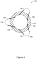
- the spacer members 30 may be spaced apart, as shown in FIG. 3 .
- spacer members 30 may overlap with an adjacent spacer member 30 around the circumference of the first end 22.
- each spacer member 30 may overlap with the adjacent spacer member 30 on each side thereof.
- the stent 10 includes three spacer members 30.
- the stent 10 may have two opposing spacer members 30, or four, five, six, or more spacer members 30 evenly or unevenly spaced around the circumference of the stent 10.
- the wire 35 forming the spacer members 30 may have the same or different properties than the wires 15 which form the tubular body 20.
- the wires 35 may be of the same or different stiffness or flexibility, all of which may be tailored for a particular application.
- the wire 35 forming spacer members 30 may be stiffer than the stent wires 15 forming the tubular body 20 of the stent 10.
- the wire 35 forming the spacer members 30 may be formed of a different material and/or may have a different diameter than the stent wires 15.
- the wire 35 forming the spacer members 30 may be stainless steel while the stent wires 15 may be formed of a nickel-titanium alloy, such as nitinol.
- the material forming the spacer member wires 35 may have a stiffness greater than, equal to, or less than the material forming the wires 15 of the tubular body 20 and/or the material forming the spacer member wires 35 may have a modulus of elasticity (Young's modulus) greater than, equal to, or less than the material forming the wires 15 of the tubular body 20.
- the choice of material, wire diameter and pre-treatment of the wires 35, 15 and stent configuration are some of the factors which may be varied to achieve particular stent properties.
- at least one of the spacer members 30 may also be made radiopaque by various methods, for example with a coating or finish, with a band or as part of the stent material. Color or different finishes may also be added to the spacer members 30 to visually differentiate them from the rest of the stent wires 15.
- the spacer members 30 are configured such that applying a pulling or squeezing force on the spacer members 30 does not reduce the outer diameter of the tubular body 20.
- the attachment is such that pulling on the spacer members 30 does not reduce the outer diameter of the tubular body 20.
- welding the spacer members 30 or using adhesive to attach the spacer members 30 to one or more wire cross-over points on the inner surface of the tubular body 20 may prevent the spacer members 30 from interacting with the weave or braided structure of the tubular body 20 to reduce its diameter when the spacer members 30 are pulled or squeezed.
- the spacer members 30 are formed from one or more wires used in forming the tubular body 20, the portion of the wire(s) forming the spacer members 30 may be stabilized relative to the tubular body 20 such that pulling on the spacer members 30 does not reduce the outer diameter of the tubular body 20.
- stabilizing may include welding one or more of the last wire cross-over points at the first end 22 of the tubular body where the wire forming the spacer member 30 exits the tubular body 20.
- adhesive or additional wire wrapping may be used to stabilize the spacer members 30 relative to the tubular body 20. The spacer members 30 thus do not function as retrieval elements to reduce the diameter of the stent 10 for removal.
- a separate retrieval element 80 may be disposed on the second end 24 and/or the first end 22 of the tubular body 20.
- the stent 10 includes a retrieval element 80 attached to the second end 24 of the tubular body 20.
- the retrieval element 80 may be a wire or suture woven through loops of the wires 15 of the tubular body 20 at the second end 24 of the tubular body 20.
- the spacer members 30 extend longitudinally beyond the first end 22 of the tubular body 20.
- the spacer members 30 may extend beyond the first end 22 of the tubular body 20 for a distance D.
- distance D may be 5% to 50%, 10% to 50%, 10% to 30%, or 5% to 30% of the total length of the tubular body 20, for example.
- the spacer members 30 may extend 8 mm to 15 mm beyond the first end 22.
- the spacer members 30 may also extend radially away from the tubular body 20, beyond the outer diameter of the tubular body 20 as measured at the first end 22. In the example shown in FIGS. 2 and 3 , the spacer members 30 also extend radially beyond the outer diameter of the anchor members 26, 28.
- the spacer members 30 may extend radially outward at an angle of between about 20 degrees to about 85 degrees, between about 25 degrees to about 75 degrees, about 30 degrees to about 60 degrees, or about 45 degrees to about 75 degrees from the longitudinal axis X of the stent 10.
- the angle of the spacer members 30 relative to the longitudinal axis X may be, for example, 25 degrees or more, 30 degrees or more, 35 degrees or more, 40 degrees or more, 45 degrees or more, 50 degrees or more, 55 degrees or more, 60 degrees or more, 65 degrees or more, 70 degrees or more, 75 degrees or more, 80 degrees or more, or 85 degrees or more degrees, or other desired angle.
- the spacer members 30 illustrated in the figures are shaped as elongated loops.
- the spacer members 30 may be any shape desired, including circular, elliptical, teardrop, etc.
- the terminal end 38 of the spacer members 30 may be rounded, as shown in FIG. 3 , to provide an atraumatic end that engages the cyst wall 40.
- the spacer members 30 may provide a structure which has the required stiffness to maintain the stent 10 in a spaced orientation away from the cyst wall 40, thus preventing damage to the tissue wall from contact with the first end 22 of the tubular body 20. According to the invention, the flexibility of the spacer members 30 varies along their length.
- the spacer members 30 may be formed from a wire having a variable thickness along its length.
- the stent 100 includes at least one spacer member 130 formed from a wire having a first thickness in the first region 136 adjacent the tubular body 120, tapering down and/or transitioning to a second thickness at the terminal end 138. As illustrated in FIG.
- the second thickness may be smaller than the first thickness to achieve a spacer member 130 that is more flexible at the terminal end 138.
- the more flexible terminal end 138 may allow the spacer member 130 to bend slightly at the terminal end 138 as it contacts the cyst wall 40, reducing the potential for tissue injury.
- the stent 10, 100 may include a covering 70, 170 disposed over at least a portion of the tubular body 20, 120 of the stent 10, 100.
- the covering 70, 170 may fully cover the entire length of the tubular body 20, 120 of the stent 10, 100, forming a fully covered stent in which all of the interstices defined in the braided or woven pattern are covered with the covering 70, 170 to prevent tissue in-growth and fluid leakage into the lumen of the tubular body 20, 120.
- the covering 70, 170 may cover only a portion of the length of the tubular body 20, 120 of the stent 10, 100, forming a partially covered stent in which a portion of the interstices defined in the braided or woven pattern remain uncovered, allowing tissue in-growth.
- the spacer members 30, 130 may be covered by the covering 70, 170, thus the entire stent 10, 100, including both the entire tubular body 20, 120 and the spacer members 30, 130 may be covered by the covering 70, 170.
- the covering 70, 170 may extend across and fill the space between adjacent sides of the loop formed by the wire(s) forming the spacer members 30, 130 while the gap between adjacent spacer members 30, 130 may be devoid of any covering material, permitting fluid to flow between the spacer members 30, 130 around the end of the stent 10, 100 and into the lumen of the stent 10, 100.
- the stent 10, 100 may be dipped into a solution of silicone or other polymer to form the covering 70, 170.
- a polymer sheet or tube may be placed around the tubular body 20, 120 and/or within the tubular body 20, 120 to form the covering 70, 170.
- the covering 70, 170 may be disposed on external or internal surfaces of the tubular body 20, 120, or on both the internal and external surfaces of the tubular body 20, 120, thereby embedding the stent 10, 100 in the polymeric material.
- the coating or covering may be a polymer covering, such as a polytetrafluoroethylene (PTFE) or silicone covering, however other coverings, particularly elastomeric polymers, may be used.
- PTFE polytetrafluoroethylene
- silicone coverings particularly elastomeric polymers
- Non-limiting examples of useful polymeric materials include polyesters, polypropylenes, polyethylenes, polyurethanes, polynaphthalenes, polytetrafluoroethylenes, expanded polytetrafluoroethylene, silicone, and combinations and copolymers thereof.
- FIG. 5 shows one end of the stent 10 of FIG. 2 implanted in a tissue site represented as a cyst.
- the first end portion of the stent 10 may be implanted through an opening in a tissue wall with the first anchor member 26, first end 22 of the tubular body 20, and three spacer members 30 all protruding through the tissue wall 46 into a cavity representing the cyst.
- the second anchor member 28 may be disposed on the other side of the tissue wall to secure the stent 10 across the tissue wall 46.
- the larger diameter of the first anchor member 26 holds the stent 10 in place and the spacer members 30 are disposed within the cyst.
- the lower cyst wall see FIG.
- the spacer members 30 prevent the wall of the cyst from contacting the first end 22 of the tubular body 20.
- the spacer members 30 hold the first end 22 of the tubular body 20 away from the cyst wall and permit fluid to pass around the first end 22 of the tubular body 20 between adjacent spacer member 30 and into the lumen of the tubular body 20 to drain the fluid from the cyst. Even when all fluid has been drained from the cyst, the cyst wall is spaced away from the first end 22 of the tubular body 20 by the spacer members 30. This spacing may reduce or eliminate tissue irritation and/or resultant bleeding.
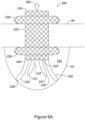
- FIGS. 6A and 6B illustrate another example of a stent 200 disposed through a tissue wall 46 with the first end 222 of the stent 200 disposed in the cavity of a cyst 242.
- the stent 200 includes a tubular body 220, a first group of spacer members 230 having a first length extending from the first region 236 adjacent the first end 222 of the tubular body 220 to the terminal end 238 of spacer members 230.
- the stent 200 includes a second group of spacer members 231 extending from the first region 237 adjacent the first end 222 of the tubular body 220 to the terminal end 239 of spacer members 231.
- the second group of spacer members 231 have a second length that is shorter than the first length of the first group of spacer members 230, positioning the terminal ends 239 of the second group of spacer members 231 closer to the first end 222 of the tubular body 220 than the terminal ends 238 of the first group of spacer members 230.
- the cyst wall 40 collapses and engages the terminal ends 238 of the first group of spacer members 230, as shown in FIG. 6A .
- the first group of spacer members 230 may flex or bend back toward the second end 224 of the tubular body 220, in the direction of arrow 250, permitting the terminal ends 239 of the second group of spacer members 231 to engage the cyst wall 40, as shown in FIG. 6B .
- the first group of spacer members 230 may be more flexible than the second group of spacer members 231, allowing the first group of spacer members 230 to flex, bend or partially collapse as the cyst wall 40 advances towards the first end 222 of the tubular body 220.
- the first and second groups of spacer members 230, 231 may have a variable flexibility along their length.
- one or both of the first and second groups of spacer members 230, 231 may have terminal ends 238 that are more flexible than first regions 236 adjacent the tubular body 320.
- the spacer members 230, 231 provide insufficient radial resistance to anchor the stent 200. Similar to the spacer members 30 discussed above, the spacer members 230, 231 are configured such that applying a pulling or squeezing force on the spacer members 230, 231 does not reduce the outer diameter of the tubular body 220.
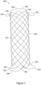
- FIG. 7 A further example of a stent 300 with a tubular body 320 and a plurality of spacer members 330 is shown in FIG. 7 .
- the tubular body 320 is formed from one or more stent wires 315 and has a substantially uniform diameter along its length, without anchor members.
- the plurality of spacer members 330 may be attached to the first end 322 of the tubular body 320, the second end 324 of the tubular body 320, or both.
- the spacer members 330 may be formed from wires 315 forming the tubular body 320, or from wires 335 attached to the tubular body 320 after the tubular body 320 has been formed.
- the wires 335 may be attached to the tubular body 320 by welding, adhesive, wire wrapping or other suitable permanent connection.
- the spacer members 330 are configured such that applying a pulling or squeezing force on the spacer members 330 does not reduce the outer diameter of the tubular body 320.
- the wires 335 may be tapered to provide a variable flexibility along the spacer member 330.
- the wires 335 may have a first thickness in the first region 336 adjacent the tubular body 320 and taper down to a second, smaller thickness in the region of the terminal end 338 of the spacer member 330, resulting in the terminal end 338 being more flexible than the first region 336.
- This allows the terminal end 338 of the spacer members 330 to flex or bend back toward the opposite end of the tubular body 320 upon contact with a tissue wall.
- the stiffer first region 336 holds the end of the tubular body 320 away from the tissue wall allowing fluid drainage around the first end 322 of the tubular body 320 into the lumen of the stent 300.
- the flexibility of the terminal end 338 of the spacer members 330 allows the spacer members 330 to gently engage the tissue wall below the stent 300, but the spacer members 330 provide insufficient radial resistance to anchor the stent 300 against lumen walls extending substantially parallel to the longitudinal axis.
- the stiffer first region 336 may provide sufficient resistance in a longitudinal direction to anchor the stent 300 disposed perpendicular to a tissue wall.
- FIG. 8 shows the first end 322 of the tubular body 320 extending through an opening in a tissue wall 46.
- the spacer members 330 have the dual function of holding the stent 300 in place within the opening in the tissue wall, and spacing the first end 322 of the tubular body 320 of the stent 300 from the tissue wall as the cyst drains.
- FIG. 9 shows another example of a stent 400 with a tubular body 420 formed from one or more wires 415 woven, braided, knitted, or wound into the tubular body 420.
- the stent 400 includes a first group of spacer members 430 having a first length extending from the first region 436 adjacent the first end 422 of the tubular body 420 to the terminal end 438 of the spacer members 430.
- the stent 400 includes a second group of spacer members 431 extending from the first region 437 adjacent the first end 422 of the tubular body 420 to the terminal end 439 of the spacer members 431.
- the second group of spacer members 431 have a second length that is shorter than the first length of the first group of spacer members 430, positioning the terminal ends 439 of the second group of spacer members 431 closer to the first end 422 of the tubular body 420 than the terminal ends 438 of the first group of spacer members 430.
- the first group of spacer members 430 may be more flexible than the second group of spacer members 431, allowing the first group of spacer members 430 to flex, bend or partially collapse as the cyst drains and the tissue wall advances towards the first end 422 of the tubular body 420.
- the tubular body 420 has a substantially uniform diameter along its length, without anchor members.
- the first and second groups of spacer members 430, 431 may be attached to the first end 422 of the tubular body 420, the second end 424 of the tubular body 420, or both.
- the spacer members 430, 431 may be formed from wires 415 forming the tubular body 420 or wires 435 attached to the tubular body 420 after the tubular body 420 has been formed.
- the spacer members 430, 431 are configured such that applying a pulling or squeezing force on the spacer members 430, 431 does not reduce the outer diameter of the tubular body 420.
- the wires 435 may be tapered to provide a variable flexibility along the spacer members 430, 431.
- the wires 435 may have a first thickness in the first region 436, 437 adjacent the tubular body 420 and taper down or transition to a second, smaller thickness in the region of the terminal end 438, 439, resulting in the terminal end 438, 439 being more flexible than the first region 436, 437.
- the stiffer first region 436, 437 holds the end of the tubular body 420 away from the tissue wall.
- the flexibility of the terminal end 438, 439 of the spacer members 430, 431 allows the spacer members 430, 431 to gently engage the tissue wall below the stent 400, but provide insufficient radial resistance to anchor the stent 400 against lumen walls extending substantially parallel to the longitudinal axis.
- the stiffer first region 436, 437 may provide sufficient resistance in a longitudinal direction to anchor the stent 400 disposed perpendicular to a tissue wall.
- stents 100, 200, 300 and 400 may include a covering, similar to covering 70, 170 described above, disposed over at least a portion of the tubular body of the stent 100, 200, 300, 400.
- the covering may fully cover the entire length of the tubular body of the stent 100, 200, 300, 400, forming a fully covered stent in which all of the interstices defined in the braided or woven pattern are covered with the covering to prevent tissue in-growth and fluid leakage into the lumen of the tubular body.
- the covering may cover only a portion of the length of the tubular body of the stent 100, 200, 300, 400, forming a partially covered stent in which a portion of the interstices defined in the braided or woven pattern remain uncovered, allowing tissue in-growth.
- the spacer members 130, 230, 330, 430 may be covered by the covering, thus the entire stent 100, 200, 300, 400, including both the entire tubular body and the spacer members 130, 230, 330, 430 may be covered by the covering.
- the covering may extend across and fill the space between adjacent sides of the loop formed by the wire(s) forming the spacer members 130, 230, 330, 430, while the gap between adjacent spacer members 130, 230, 330, 430 may be devoid of any covering material, permitting fluid to flow between the spacer members 130, 230, 330, 430 around the end of the stent 100, 200, 300, 400 and into the lumen of the stent 100, 200, 300, 400.
- the stent 10, 100, 200, 300, 400 may be a self-expanding stent or a balloon expandable stent.
- the stent 10, 100, 200, 300, 400 may be capable of radially contracting to a compressed or collapsed configuration for delivery, and then expandable to an expanded configuration during deployment in the body lumen.
- the stent 10, 100, 200, 300, 400 may be described as radially distensible or deformable.
- Self-expanding stents include those that have a spring-like action which causes the stent to radially expand, or stents which expand due to the memory properties of the stent material for a particular configuration at a certain temperature.
- the configuration of the stent may also be chosen from a host of geometries.
- wire stents can be fastened into a continuous helical pattern, with or without a wave-like or zig-zag in the wire, to form a radially deformable stent.
- Individual rings or circular members can be linked together such as by struts, sutures, welding or interlacing or locking of the rings to form a tubular stent.
- the stent 10, 100, 200, 300, 400 may be formed as a monolithic tubular member by etching or cutting a pattern of interconnected struts from a tube.
- the invention's scope is, of course, defined in the language in which the appended claims are expressed.
Claims (14)
- Stent (10; 100; 200; 300; 400) comprenant:un corps tubulaire (20; 120; 220; 320; 420) formé d'un ou plusieurs fils entrelacés (15; 315; 415), le corps tubulaire (20; 120; 220; 320; 420) ayant des première et seconde extrémités ouvertes opposées (22, 24; 222, 224; 322, 324; 422; 424) et une lumière s'étendant entre elles;un premier élément d'ancrage (26; 226) disposé de manière adjacente à la première extrémité ouverte (22; 222; 322; 422) et un second élément d'ancrage (28; 228) disposé de manière adjacente à la seconde extrémité ouverte (24; 224; 324; 424), les premier et second éléments d'ancrage (26, 28; 226, 228) s'étendant chacun radialement vers l'extérieur depuis le corps tubulaire (20; 120; 220; 320; 420), les premier et second éléments d'ancrage (26, 28; 226, 228) ayant chacun un diamètre externe supérieur à un diamètre externe du corps tubulaire (20; 120; 220; 320; 420) disposé entre les premier et second éléments d'ancrage (26, 28; 226, 228); etune pluralité d'éléments d'espacement (30; 130; 230; 231; 330; 430; 431) disposés autour de la première extrémité ouverte (22; 222; 322; 422) et s'étendant longitudinalement au-delà de la première extrémité ouverte (22; 222; 322; 422), dans lequel lorsqu'une force de traction est appliquée aux éléments d'espacement (30; 130; 230; 231; 330; 430; 431), le diamètre externe du corps tubulaire (20; 120; 220; 320; 420) n'est pas réduit,dans lequel au moins un élément d'espacement (30; 130; 230; 231; 330; 430; 431) a une flexibilité variable le long de sa longueur.
- Stent (10; 100; 200; 300; 400) selon la revendication 1, dans lequel chaque élément d'espacement (30; 130; 230; 231; 330; 430; 431) a des première et seconde pattes (32, 34) s'étendant le long d'une partie du corps tubulaire (20; 120; 220; 320; 420) vers la seconde extrémité ouverte (24; 224; 324; 424).
- Stent (10; 100; 200; 300; 400) selon la revendication 1 ou 2, dans lequel les éléments d'espacement (30; 130; 230; 231; 330; 430; 431) s'étendent radialement vers l'extérieur au-delà du diamètre externe du corps tubulaire (20; 120; 220; 320; 420).
- Stent (10) selon l'une quelconque des revendications 1 à 3, dans lequel chaque élément d'espacement (30) est formé à partir d'une seule boucle de fil (35).
- Stent (10) selon l'une quelconque des revendications 1 à 4, dans lequel les éléments d'espacement (30) sont formés séparément du corps tubulaire (20) et fixés à une paroi interne du corps tubulaire (20).
- Stent (10; 100; 200; 300; 400) selon l'une quelconque des revendications 1 à 4, dans lequel les éléments d'espacement (30; 130; 230; 231; 330; 430; 431) sont entrelacés avec le corps tubulaire (20; 120; 220; 320; 420).
- Stent (10; 100; 200; 300; 400) selon l'une quelconque des revendications 1 à 6, dans lequel les éléments d'espacement (30; 130; 230; 231; 330; 430; 431) sont moins flexibles que le corps tubulaire (20; 120; 220; 320; 420).
- Stent (200; 400) selon l'une quelconque des revendications 1 à 7, dans lequel la pluralité d'éléments d'espacement (230, 231; 430, 431) inclut un premier groupe d'éléments d'espacement (230; 430) avec une première longueur et un second groupe d'éléments d'espacement (231; 431) ayant une seconde longueur plus courte que la première longueur.
- Stent (200; 400) selon la revendication 8, dans lequel le premier groupe d'éléments d'espacement (230; 430) est plus flexible que le second groupe d'éléments d'espacement (231; 431).
- Stent (10; 100; 200; 300; 400) selon l'une quelconque des revendications 1 à 9, comprenant en outre un revêtement (70; 170) s'étendant sur une totalité du corps tubulaire (20; 120; 220; 320; 420), les premier et second éléments d'ancrage (26, 28; 226, 228) et la pluralité d'éléments d'espacement (30; 130; 230; 231; 330; 430; 431).
- Stent (100; 300; 400) selon l'une quelconque des revendications 1 à 10, dans lequel le au moins un élément d'espacement (130; 330; 430; 431) est formé à partir d'un fil aminci (135; 335; 435) ayant une première épaisseur dans une première région (136; 336; 436; 437) adjacente au corps tubulaire (120; 320; 420), et une seconde épaisseur dans une seconde région (138; 338; 438; 439) disposée le plus loin du corps tubulaire (120; 320; 420).
- Stent (100; 300; 400) selon la revendication 11, dans lequel la seconde épaisseur est inférieure à la première épaisseur, ce qui conduit à une plus grande flexibilité dans la seconde région (138; 338; 438; 439).
- Stent (10; 100; 200; 300; 400) selon l'une quelconque des revendications 1 à 12, dans lequel le corps tubulaire (20; 120; 220; 320; 420) définit un axe longitudinal s'étendant entre les première et seconde extrémités ouvertes (22, 24; 222, 224; 322, 324; 422; 424), dans lequel les premier et second éléments d'ancrage (26, 28; 226, 228) s'étendent perpendiculairement à l'axe longitudinal.
- Stent (10) selon l'une quelconque des revendications 1 à 13, comprenant en outre un élément de récupération (80) disposé au niveau de la seconde extrémité ouverte (24).
Priority Applications (1)
| Application Number | Priority Date | Filing Date | Title |
|---|---|---|---|
| EP23183488.8A EP4238539A3 (fr) | 2017-10-25 | 2018-10-24 | Stent avec espaceur atraumatique |
Applications Claiming Priority (2)
| Application Number | Priority Date | Filing Date | Title |
|---|---|---|---|
| US201762576890P | 2017-10-25 | 2017-10-25 | |
| PCT/US2018/057308 WO2019084136A1 (fr) | 2017-10-25 | 2018-10-24 | Stent avec espaceur atraumatique |
Related Child Applications (2)
| Application Number | Title | Priority Date | Filing Date |
|---|---|---|---|
| EP23183488.8A Division EP4238539A3 (fr) | 2017-10-25 | 2018-10-24 | Stent avec espaceur atraumatique |
| EP23183488.8A Division-Into EP4238539A3 (fr) | 2017-10-25 | 2018-10-24 | Stent avec espaceur atraumatique |
Publications (2)
| Publication Number | Publication Date |
|---|---|
| EP3700474A1 EP3700474A1 (fr) | 2020-09-02 |
| EP3700474B1 true EP3700474B1 (fr) | 2023-08-23 |
Family
ID=64500446
Family Applications (2)
| Application Number | Title | Priority Date | Filing Date |
|---|---|---|---|
| EP18811102.5A Active EP3700474B1 (fr) | 2017-10-25 | 2018-10-24 | Stent avec espaceur atraumatique |
| EP23183488.8A Pending EP4238539A3 (fr) | 2017-10-25 | 2018-10-24 | Stent avec espaceur atraumatique |
Family Applications After (1)
| Application Number | Title | Priority Date | Filing Date |
|---|---|---|---|
| EP23183488.8A Pending EP4238539A3 (fr) | 2017-10-25 | 2018-10-24 | Stent avec espaceur atraumatique |
Country Status (7)
| Country | Link |
|---|---|
| US (2) | US11304795B2 (fr) |
| EP (2) | EP3700474B1 (fr) |
| JP (3) | JP6989698B2 (fr) |
| KR (2) | KR102614314B1 (fr) |
| CN (2) | CN111356420B (fr) |
| CA (1) | CA3079094C (fr) |
| WO (1) | WO2019084136A1 (fr) |
Families Citing this family (1)
| Publication number | Priority date | Publication date | Assignee | Title |
|---|---|---|---|---|
| WO2023192516A1 (fr) * | 2022-03-31 | 2023-10-05 | Boston Scientific Scimed, Inc. | Dispositif médical implantable comprenant des indicateurs visuels |
Family Cites Families (100)
| Publication number | Priority date | Publication date | Assignee | Title |
|---|---|---|---|---|
| US5064435A (en) | 1990-06-28 | 1991-11-12 | Schneider (Usa) Inc. | Self-expanding prosthesis having stable axial length |
| EP0633798B1 (fr) | 1992-03-31 | 2003-05-07 | Boston Scientific Corporation | Filtre vasculaire |
| US7101392B2 (en) | 1992-03-31 | 2006-09-05 | Boston Scientific Corporation | Tubular medical endoprostheses |
| US5474563A (en) | 1993-03-25 | 1995-12-12 | Myler; Richard | Cardiovascular stent and retrieval apparatus |
| US5632772A (en) * | 1993-10-21 | 1997-05-27 | Corvita Corporation | Expandable supportive branched endoluminal grafts |
| US5989280A (en) | 1993-10-22 | 1999-11-23 | Scimed Lifesystems, Inc | Stent delivery apparatus and method |
| RU2089131C1 (ru) | 1993-12-28 | 1997-09-10 | Сергей Апполонович Пульнев | Стент |
| US5575816A (en) | 1994-08-12 | 1996-11-19 | Meadox Medicals, Inc. | High strength and high density intraluminal wire stent |
| BE1009278A3 (fr) * | 1995-04-12 | 1997-01-07 | Corvita Europ | Tuteur auto-expansible pour dispositif medical a introduire dans une cavite d'un corps, et dispositif medical muni d'un tel tuteur. |
| BE1009277A3 (fr) | 1995-04-12 | 1997-01-07 | Corvita Europ | Tuteur auto-expansible pour dispositif medical a introduire dans une cavite d'un corps, et son procede de preparation. |
| JPH09215753A (ja) | 1996-02-08 | 1997-08-19 | Schneider Usa Inc | チタン合金製自己拡張型ステント |
| US5941895A (en) | 1996-09-04 | 1999-08-24 | Hemodynamics, Inc. | Cardiovascular stent and retrieval apparatus |
| US6241757B1 (en) | 1997-02-04 | 2001-06-05 | Solco Surgical Instrument Co., Ltd. | Stent for expanding body's lumen |
| EP0975279B1 (fr) | 1997-04-15 | 2007-05-02 | Schneider (Usa) Inc. | Prothèses à brins croisés sélectivement soudés |
| US5836966A (en) | 1997-05-22 | 1998-11-17 | Scimed Life Systems, Inc. | Variable expansion force stent |
| ATE286687T1 (de) | 1997-07-17 | 2005-01-15 | Schneider Europ Gmbh | Stent sowie herstellungsverfahren dafür |
| US6174330B1 (en) | 1997-08-01 | 2001-01-16 | Schneider (Usa) Inc | Bioabsorbable marker having radiopaque constituents |
| US6254642B1 (en) | 1997-12-09 | 2001-07-03 | Thomas V. Taylor | Perorally insertable gastroesophageal anti-reflux valve prosthesis and tool for implantation thereof |
| US6626939B1 (en) | 1997-12-18 | 2003-09-30 | Boston Scientific Scimed, Inc. | Stent-graft with bioabsorbable structural support |
| US6264689B1 (en) | 1998-03-31 | 2001-07-24 | Scimed Life Systems, Incorporated | Low profile medical stent |
| US6520983B1 (en) | 1998-03-31 | 2003-02-18 | Scimed Life Systems, Inc. | Stent delivery system |
| US5980533A (en) | 1998-06-09 | 1999-11-09 | Scimed Life Systems, Inc. | Stent delivery system |
| US6120522A (en) | 1998-08-27 | 2000-09-19 | Scimed Life Systems, Inc. | Self-expanding stent delivery catheter |
| DK1109511T3 (da) | 1998-08-31 | 2004-03-15 | Wilson Cook Medical Inc | Tilbageløbshindrende spiserørsprotese |
| US7018401B1 (en) | 1999-02-01 | 2006-03-28 | Board Of Regents, The University Of Texas System | Woven intravascular devices and methods for making the same and apparatus for delivery of the same |
| AU6000200A (en) | 1999-07-16 | 2001-02-05 | Biocompatibles Limited | Braided stent |
| US6409753B1 (en) | 1999-10-26 | 2002-06-25 | Scimed Life Systems, Inc. | Flexible stent |
| US6585758B1 (en) | 1999-11-16 | 2003-07-01 | Scimed Life Systems, Inc. | Multi-section filamentary endoluminal stent |
| US6468303B1 (en) | 2000-03-27 | 2002-10-22 | Aga Medical Corporation | Retrievable self expanding shunt |
| US6569181B1 (en) | 2000-12-20 | 2003-05-27 | Advanced Cardiovascular Systems, Inc. | Stent retrieval system |
| US6620122B2 (en) | 2001-04-26 | 2003-09-16 | Scimed Life Systems, Inc. | Gastric pseudocyst drainage and stent delivery system for use therein |
| US6663663B2 (en) | 2001-05-14 | 2003-12-16 | M.I. Tech Co., Ltd. | Stent |
| US6821291B2 (en) | 2001-06-01 | 2004-11-23 | Ams Research Corporation | Retrievable stent and method of use thereof |
| CA2450959C (fr) | 2001-06-20 | 2011-01-04 | Park Medical, Llc | Dispositif anastomotique |
| US7175655B1 (en) | 2001-09-17 | 2007-02-13 | Endovascular Technologies, Inc. | Avoiding stress-induced martensitic transformation in nickel titanium alloys used in medical devices |
| US20030083734A1 (en) | 2001-10-25 | 2003-05-01 | Curative Ag | Stent |
| EP1469794B1 (fr) | 2002-01-28 | 2009-03-18 | OrbusNeich Medical, Inc. | Endoprothese ostiale evasee et systeme d'apport |
| US7001425B2 (en) | 2002-11-15 | 2006-02-21 | Scimed Life Systems, Inc. | Braided stent method for its manufacture |
| US20040102855A1 (en) | 2002-11-21 | 2004-05-27 | Scimed Life Systems, Inc. | Anti-reflux stent |
| US7608114B2 (en) | 2002-12-02 | 2009-10-27 | Gi Dynamics, Inc. | Bariatric sleeve |
| ES2364555T3 (es) * | 2003-05-23 | 2011-09-06 | Boston Scientific Limited | Cánulas con terminaciones en bucle incorporadas. |
| US7476256B2 (en) | 2003-12-09 | 2009-01-13 | Gi Dynamics, Inc. | Intestinal sleeve |
| US20050131515A1 (en) | 2003-12-16 | 2005-06-16 | Cully Edward H. | Removable stent-graft |
| US7763011B2 (en) | 2003-12-22 | 2010-07-27 | Boston Scientific Scimed, Inc. | Variable density braid stent |
| US20050154447A1 (en) * | 2004-01-09 | 2005-07-14 | Medtronic Vascular, Inc. | Ostium stent system |
| US20050228413A1 (en) | 2004-04-12 | 2005-10-13 | Binmoeller Kenneth F | Automated transluminal tissue targeting and anchoring devices and methods |
| US8425539B2 (en) | 2004-04-12 | 2013-04-23 | Xlumena, Inc. | Luminal structure anchoring devices and methods |
| US7993387B2 (en) | 2004-05-14 | 2011-08-09 | Boston Scientific Scimed, Inc. | Stent with reduced weld profiles and a closed-end wire configuration |
| JP2008513129A (ja) | 2004-09-17 | 2008-05-01 | ジーアイ・ダイナミックス・インコーポレーテッド | 内腔内アンカ装置 |
| ATE543469T1 (de) | 2004-11-10 | 2012-02-15 | Boston Scient Scimed Inc | Atraumatischer stent mit verringerter ablagekraft und verfahren zu seiner herstellung |
| WO2006081448A1 (fr) * | 2005-01-28 | 2006-08-03 | Boston Scientific Limited | Element de reperage de tuteur intravasculaire, dispositifs et procedes de reperage ou de repositionnement de tuteur intravasculaire |
| EP1887974B1 (fr) | 2005-05-13 | 2018-04-25 | Boston Scientific Limited | Stent integre presentant une boucle de repositionnement et d'extraction |
| US8109962B2 (en) | 2005-06-20 | 2012-02-07 | Cook Medical Technologies Llc | Retrievable device having a reticulation portion with staggered struts |
| WO2007016166A2 (fr) | 2005-07-27 | 2007-02-08 | Cook Critical Care Incorporated | Endoprothese couverte et procede d'implantation chirurgicale ouverte |
| US7670369B2 (en) | 2005-10-13 | 2010-03-02 | Cook Incorporated | Endoluminal prosthesis |
| US20070179590A1 (en) | 2005-12-29 | 2007-08-02 | Wenfeng Lu | Hybrid intraluminal device with varying expansion force |
| US8105392B2 (en) | 2006-11-08 | 2012-01-31 | Boston Scientific Scimed, Inc. | Pyloric obesity valve |
| US8221505B2 (en) | 2007-02-22 | 2012-07-17 | Cook Medical Technologies Llc | Prosthesis having a sleeve valve |
| US20080228256A1 (en) | 2007-03-13 | 2008-09-18 | Medtronic Vascular, Inc. | Braided Flange Branch Graft for Branch Vessel |
| BRPI0819217B8 (pt) | 2007-10-25 | 2021-06-22 | Symetis Sa | válvula de substituição para uso dentro de um corpo humano, sistema para substituir uma válvula dentro de um corpo humano e sistema de liberação da válvula cardíaca com stent |
| US8623071B2 (en) * | 2008-01-07 | 2014-01-07 | DePuy Synthes Products, LLC | Radiopaque super-elastic intravascular stent |
| US20090276040A1 (en) | 2008-05-01 | 2009-11-05 | Edwards Lifesciences Corporation | Device and method for replacing mitral valve |
| US8454632B2 (en) | 2008-05-12 | 2013-06-04 | Xlumena, Inc. | Tissue anchor for securing tissue layers |
| US20090281379A1 (en) | 2008-05-12 | 2009-11-12 | Xlumena, Inc. | System and method for transluminal access |
| US8114147B2 (en) | 2008-06-16 | 2012-02-14 | Boston Scientific Scimed, Inc. | Continuous double layered stent for migration resistance |
| US20110190662A1 (en) * | 2008-10-01 | 2011-08-04 | Beacon Endoscopic Corporation | Rapid exchange fna biopsy device with diagnostic and therapeutic capabilities |
| US8151682B2 (en) | 2009-01-26 | 2012-04-10 | Boston Scientific Scimed, Inc. | Atraumatic stent and method and apparatus for making the same |
| US9173760B2 (en) | 2009-04-03 | 2015-11-03 | Metamodix, Inc. | Delivery devices and methods for gastrointestinal implants |
| KR20120008492A (ko) | 2009-04-03 | 2012-01-30 | 메타모딕스, 인코포레이티드 | 모듈형 위장 보철물 |
| US8357193B2 (en) | 2009-05-29 | 2013-01-22 | Xlumena, Inc. | Apparatus and method for deploying stent across adjacent tissue layers |
| US20100305590A1 (en) | 2009-05-29 | 2010-12-02 | Gi Dynamics, Inc. | Transpyloric Anchoring |
| GB2472603B (en) * | 2009-08-11 | 2011-12-14 | Cook Medical Technologies Llc | Implantable medical device |
| US8784473B2 (en) * | 2009-09-10 | 2014-07-22 | Boston Scientific Scimed, Inc. | Endoprosthesis with filament repositioning or retrieval member and guard structure |
| CN102548513B (zh) | 2009-09-21 | 2017-03-08 | 波士顿科学国际有限公司 | 适用于圈套器取出及/或优化褶皱拉平的一体支架取出环 |
| WO2011073970A1 (fr) | 2009-12-18 | 2011-06-23 | Vysera Biomedical Limited | Dispositif d'implant gastro-intestinal |
| WO2011136963A1 (fr) | 2010-04-30 | 2011-11-03 | Boston Scientific Scimed, Inc. | Endoprothèse métabolique duodénale |
| US9526648B2 (en) | 2010-06-13 | 2016-12-27 | Synerz Medical, Inc. | Intragastric device for treating obesity |
| US9867725B2 (en) * | 2010-12-13 | 2018-01-16 | Microvention, Inc. | Stent |
| US20120310319A1 (en) | 2010-12-21 | 2012-12-06 | Tieu Tai D | Stent |
| US9028540B2 (en) | 2011-03-25 | 2015-05-12 | Covidien Lp | Vascular stent with improved vessel wall apposition |
| US9387099B2 (en) | 2011-08-04 | 2016-07-12 | Cook Medical Technologies Llc | Non-woven helical wire stent |
| BR112014014025B1 (pt) | 2011-12-19 | 2021-05-04 | Coloplast A/S | prótese luminal autoexpansível |
| FR2984724B1 (fr) | 2011-12-23 | 2014-01-24 | Assist Publ Hopitaux De Paris | Prothese expansive destinee a etre implantee dans le tube digestif d'un patient. |
| AU2013231845B2 (en) | 2012-03-16 | 2017-07-06 | Terumo Corporation | Stent and stent delivery device |
| JP6139664B2 (ja) * | 2012-09-12 | 2017-05-31 | ボストン サイエンティフィック サイムド,インコーポレイテッドBoston Scientific Scimed,Inc. | ステントおよびステントの作製方法 |
| AU2012258395B1 (en) | 2012-11-27 | 2013-03-28 | Cook Medical Technologies Llc | Assembly of stent grafts with diameter reducing ties |
| US20140156020A1 (en) | 2012-12-04 | 2014-06-05 | Shanda Haley Blackmon | Stent system and methods of use |
| CA2902775C (fr) | 2013-02-28 | 2017-11-28 | Boston Scientific Scimed, Inc. | Dispositifs medicaux pour utilisation le long du tractus biliaire et/ou pancreatique |
| CN105873547B (zh) | 2013-11-08 | 2019-05-03 | 波士顿科学国际有限公司 | 腔内装置 |
| US20150282922A1 (en) | 2014-04-08 | 2015-10-08 | Boston Scientific Scimed Inc. | Partially coated stents |
| JP6311066B2 (ja) * | 2014-05-28 | 2018-04-11 | ボストン サイエンティフィック サイムド,インコーポレイテッドBoston Scientific Scimed,Inc. | ステント運搬システム |
| US9801749B2 (en) | 2014-09-18 | 2017-10-31 | Boston Scientific Scimed, Inc. | Methods allowing pyloric sphincter to normally function for bariatric stents |
| EP3258891A1 (fr) * | 2015-02-20 | 2017-12-27 | Boston Scientific Scimed, Inc. | Endoprothèse vasculaire à ancrages rétractables |
| RU2019101908A (ru) | 2015-07-20 | 2019-03-05 | Стратака Системз Лимитед | Катетерное устройство и способ создания отрицательного давления в мочевом пузыре пациента |
| EP3349669B1 (fr) | 2015-09-18 | 2020-10-21 | Terumo Corporation | Prothèse de vaisseau |
| US10470904B2 (en) * | 2016-05-18 | 2019-11-12 | Boston Scientific Scimed, Inc. | Stent retrieval system |
| CN110167491A (zh) * | 2016-11-09 | 2019-08-23 | 波士顿科学国际有限公司 | 具有移位能力的支架 |
| CN110603008B (zh) * | 2017-03-02 | 2022-04-29 | 波士顿科学国际有限公司 | 包括内衬里的食管支架 |
| US10744009B2 (en) * | 2017-03-15 | 2020-08-18 | Merit Medical Systems, Inc. | Transluminal stents and related methods |
| WO2018183591A1 (fr) * | 2017-03-30 | 2018-10-04 | Boston Scientific Scimed, Inc. | Endoprothèses avec caractéristiques d'ancrage à double paroi tissulaire |
-
2018
- 2018-10-24 KR KR1020227029012A patent/KR102614314B1/ko active IP Right Grant
- 2018-10-24 EP EP18811102.5A patent/EP3700474B1/fr active Active
- 2018-10-24 KR KR1020207014368A patent/KR102436996B1/ko active IP Right Grant
- 2018-10-24 JP JP2020523380A patent/JP6989698B2/ja active Active
- 2018-10-24 WO PCT/US2018/057308 patent/WO2019084136A1/fr unknown
- 2018-10-24 EP EP23183488.8A patent/EP4238539A3/fr active Pending
- 2018-10-24 CN CN201880069606.7A patent/CN111356420B/zh active Active
- 2018-10-24 CA CA3079094A patent/CA3079094C/fr active Active
- 2018-10-24 US US16/169,370 patent/US11304795B2/en active Active
- 2018-10-24 CN CN202210666808.8A patent/CN115006052A/zh active Pending
-
2021
- 2021-12-02 JP JP2021195995A patent/JP7324267B2/ja active Active
-
2022
- 2022-03-29 US US17/707,318 patent/US20220218461A1/en active Pending
-
2023
- 2023-07-28 JP JP2023123348A patent/JP2023134841A/ja active Pending
Also Published As
| Publication number | Publication date |
|---|---|
| CA3079094A1 (fr) | 2019-05-02 |
| KR102436996B1 (ko) | 2022-08-26 |
| EP4238539A2 (fr) | 2023-09-06 |
| US11304795B2 (en) | 2022-04-19 |
| US20220218461A1 (en) | 2022-07-14 |
| US20190117370A1 (en) | 2019-04-25 |
| KR20200074974A (ko) | 2020-06-25 |
| EP4238539A3 (fr) | 2023-10-18 |
| CN111356420B (zh) | 2022-07-08 |
| JP6989698B2 (ja) | 2022-01-05 |
| CA3079094C (fr) | 2022-07-12 |
| CN115006052A (zh) | 2022-09-06 |
| JP2021500181A (ja) | 2021-01-07 |
| KR102614314B1 (ko) | 2023-12-14 |
| KR20220123320A (ko) | 2022-09-06 |
| JP7324267B2 (ja) | 2023-08-09 |
| CN111356420A (zh) | 2020-06-30 |
| JP2023134841A (ja) | 2023-09-27 |
| WO2019084136A1 (fr) | 2019-05-02 |
| EP3700474A1 (fr) | 2020-09-02 |
| JP2022019920A (ja) | 2022-01-27 |
Similar Documents
| Publication | Publication Date | Title |
|---|---|---|
| EP3597256B1 (fr) | Stent intégré présentant une boucle de repositionnement et d'extraction | |
| US10265203B2 (en) | Stent retrieval member and devices and methods for retrieving or repositioning a stent | |
| US6019779A (en) | Multi-filar coil medical stent | |
| US8672992B2 (en) | Stent and stent-graft having one or more conformance struts | |
| US11678970B2 (en) | Device for anastomotic bypass | |
| KR20180026807A (ko) | 관내 디바이스 | |
| US20220218461A1 (en) | Stent with atraumatic spacer | |
| US9610179B2 (en) | Atraumatic stent crowns | |
| EP2745806B1 (fr) | Conceptions de stents destinés au repliement réduit d'une matière de greffon |
Legal Events
| Date | Code | Title | Description |
|---|---|---|---|
| STAA | Information on the status of an ep patent application or granted ep patent |
Free format text: STATUS: UNKNOWN |
|
| STAA | Information on the status of an ep patent application or granted ep patent |
Free format text: STATUS: THE INTERNATIONAL PUBLICATION HAS BEEN MADE |
|
| PUAI | Public reference made under article 153(3) epc to a published international application that has entered the european phase |
Free format text: ORIGINAL CODE: 0009012 |
|
| STAA | Information on the status of an ep patent application or granted ep patent |
Free format text: STATUS: REQUEST FOR EXAMINATION WAS MADE |
|
| 17P | Request for examination filed |
Effective date: 20200523 |
|
| AK | Designated contracting states |
Kind code of ref document: A1 Designated state(s): AL AT BE BG CH CY CZ DE DK EE ES FI FR GB GR HR HU IE IS IT LI LT LU LV MC MK MT NL NO PL PT RO RS SE SI SK SM TR |
|
| AX | Request for extension of the european patent |
Extension state: BA ME |
|
| DAV | Request for validation of the european patent (deleted) | ||
| DAX | Request for extension of the european patent (deleted) | ||
| GRAP | Despatch of communication of intention to grant a patent |
Free format text: ORIGINAL CODE: EPIDOSNIGR1 |
|
| STAA | Information on the status of an ep patent application or granted ep patent |
Free format text: STATUS: GRANT OF PATENT IS INTENDED |
|
| INTG | Intention to grant announced |
Effective date: 20230314 |
|
| GRAS | Grant fee paid |
Free format text: ORIGINAL CODE: EPIDOSNIGR3 |
|
| GRAA | (expected) grant |
Free format text: ORIGINAL CODE: 0009210 |
|
| STAA | Information on the status of an ep patent application or granted ep patent |
Free format text: STATUS: THE PATENT HAS BEEN GRANTED |
|
| AK | Designated contracting states |
Kind code of ref document: B1 Designated state(s): AL AT BE BG CH CY CZ DE DK EE ES FI FR GB GR HR HU IE IS IT LI LT LU LV MC MK MT NL NO PL PT RO RS SE SI SK SM TR |
|
| REG | Reference to a national code |
Ref country code: GB Ref legal event code: FG4D |
|
| REG | Reference to a national code |
Ref country code: CH Ref legal event code: EP |
|
| REG | Reference to a national code |
Ref country code: IE Ref legal event code: FG4D |
|
| REG | Reference to a national code |
Ref country code: DE Ref legal event code: R096 Ref document number: 602018056040 Country of ref document: DE |
|
| PGFP | Annual fee paid to national office [announced via postgrant information from national office to epo] |
Ref country code: NL Payment date: 20230922 Year of fee payment: 6 Ref country code: IE Payment date: 20230921 Year of fee payment: 6 Ref country code: GB Payment date: 20230920 Year of fee payment: 6 |
|
| REG | Reference to a national code |
Ref country code: NL Ref legal event code: FP |
|
| REG | Reference to a national code |
Ref country code: LT Ref legal event code: MG9D |
|
| REG | Reference to a national code |
Ref country code: AT Ref legal event code: MK05 Ref document number: 1601703 Country of ref document: AT Kind code of ref document: T Effective date: 20230823 |
|
| PG25 | Lapsed in a contracting state [announced via postgrant information from national office to epo] |
Ref country code: GR Free format text: LAPSE BECAUSE OF FAILURE TO SUBMIT A TRANSLATION OF THE DESCRIPTION OR TO PAY THE FEE WITHIN THE PRESCRIBED TIME-LIMIT Effective date: 20231124 |
|
| PG25 | Lapsed in a contracting state [announced via postgrant information from national office to epo] |
Ref country code: IS Free format text: LAPSE BECAUSE OF FAILURE TO SUBMIT A TRANSLATION OF THE DESCRIPTION OR TO PAY THE FEE WITHIN THE PRESCRIBED TIME-LIMIT Effective date: 20231223 |
|
| PG25 | Lapsed in a contracting state [announced via postgrant information from national office to epo] |
Ref country code: SE Free format text: LAPSE BECAUSE OF FAILURE TO SUBMIT A TRANSLATION OF THE DESCRIPTION OR TO PAY THE FEE WITHIN THE PRESCRIBED TIME-LIMIT Effective date: 20230823 Ref country code: RS Free format text: LAPSE BECAUSE OF FAILURE TO SUBMIT A TRANSLATION OF THE DESCRIPTION OR TO PAY THE FEE WITHIN THE PRESCRIBED TIME-LIMIT Effective date: 20230823 Ref country code: PT Free format text: LAPSE BECAUSE OF FAILURE TO SUBMIT A TRANSLATION OF THE DESCRIPTION OR TO PAY THE FEE WITHIN THE PRESCRIBED TIME-LIMIT Effective date: 20231226 Ref country code: NO Free format text: LAPSE BECAUSE OF FAILURE TO SUBMIT A TRANSLATION OF THE DESCRIPTION OR TO PAY THE FEE WITHIN THE PRESCRIBED TIME-LIMIT Effective date: 20231123 Ref country code: LV Free format text: LAPSE BECAUSE OF FAILURE TO SUBMIT A TRANSLATION OF THE DESCRIPTION OR TO PAY THE FEE WITHIN THE PRESCRIBED TIME-LIMIT Effective date: 20230823 Ref country code: LT Free format text: LAPSE BECAUSE OF FAILURE TO SUBMIT A TRANSLATION OF THE DESCRIPTION OR TO PAY THE FEE WITHIN THE PRESCRIBED TIME-LIMIT Effective date: 20230823 Ref country code: IS Free format text: LAPSE BECAUSE OF FAILURE TO SUBMIT A TRANSLATION OF THE DESCRIPTION OR TO PAY THE FEE WITHIN THE PRESCRIBED TIME-LIMIT Effective date: 20231223 Ref country code: HR Free format text: LAPSE BECAUSE OF FAILURE TO SUBMIT A TRANSLATION OF THE DESCRIPTION OR TO PAY THE FEE WITHIN THE PRESCRIBED TIME-LIMIT Effective date: 20230823 Ref country code: GR Free format text: LAPSE BECAUSE OF FAILURE TO SUBMIT A TRANSLATION OF THE DESCRIPTION OR TO PAY THE FEE WITHIN THE PRESCRIBED TIME-LIMIT Effective date: 20231124 Ref country code: FI Free format text: LAPSE BECAUSE OF FAILURE TO SUBMIT A TRANSLATION OF THE DESCRIPTION OR TO PAY THE FEE WITHIN THE PRESCRIBED TIME-LIMIT Effective date: 20230823 Ref country code: AT Free format text: LAPSE BECAUSE OF FAILURE TO SUBMIT A TRANSLATION OF THE DESCRIPTION OR TO PAY THE FEE WITHIN THE PRESCRIBED TIME-LIMIT Effective date: 20230823 |
|
| PGFP | Annual fee paid to national office [announced via postgrant information from national office to epo] |
Ref country code: DE Payment date: 20230920 Year of fee payment: 6 |
|
| PG25 | Lapsed in a contracting state [announced via postgrant information from national office to epo] |
Ref country code: PL Free format text: LAPSE BECAUSE OF FAILURE TO SUBMIT A TRANSLATION OF THE DESCRIPTION OR TO PAY THE FEE WITHIN THE PRESCRIBED TIME-LIMIT Effective date: 20230823 |
|
| PG25 | Lapsed in a contracting state [announced via postgrant information from national office to epo] |
Ref country code: ES Free format text: LAPSE BECAUSE OF FAILURE TO SUBMIT A TRANSLATION OF THE DESCRIPTION OR TO PAY THE FEE WITHIN THE PRESCRIBED TIME-LIMIT Effective date: 20230823 |
|
| PG25 | Lapsed in a contracting state [announced via postgrant information from national office to epo] |
Ref country code: SM Free format text: LAPSE BECAUSE OF FAILURE TO SUBMIT A TRANSLATION OF THE DESCRIPTION OR TO PAY THE FEE WITHIN THE PRESCRIBED TIME-LIMIT Effective date: 20230823 Ref country code: RO Free format text: LAPSE BECAUSE OF FAILURE TO SUBMIT A TRANSLATION OF THE DESCRIPTION OR TO PAY THE FEE WITHIN THE PRESCRIBED TIME-LIMIT Effective date: 20230823 Ref country code: ES Free format text: LAPSE BECAUSE OF FAILURE TO SUBMIT A TRANSLATION OF THE DESCRIPTION OR TO PAY THE FEE WITHIN THE PRESCRIBED TIME-LIMIT Effective date: 20230823 Ref country code: EE Free format text: LAPSE BECAUSE OF FAILURE TO SUBMIT A TRANSLATION OF THE DESCRIPTION OR TO PAY THE FEE WITHIN THE PRESCRIBED TIME-LIMIT Effective date: 20230823 Ref country code: DK Free format text: LAPSE BECAUSE OF FAILURE TO SUBMIT A TRANSLATION OF THE DESCRIPTION OR TO PAY THE FEE WITHIN THE PRESCRIBED TIME-LIMIT Effective date: 20230823 Ref country code: CZ Free format text: LAPSE BECAUSE OF FAILURE TO SUBMIT A TRANSLATION OF THE DESCRIPTION OR TO PAY THE FEE WITHIN THE PRESCRIBED TIME-LIMIT Effective date: 20230823 Ref country code: SK Free format text: LAPSE BECAUSE OF FAILURE TO SUBMIT A TRANSLATION OF THE DESCRIPTION OR TO PAY THE FEE WITHIN THE PRESCRIBED TIME-LIMIT Effective date: 20230823 |