EP3699685B1 - Ising-modellberechnungsvorrichtung - Google Patents
Ising-modellberechnungsvorrichtung Download PDFInfo
- Publication number
- EP3699685B1 EP3699685B1 EP18867887.4A EP18867887A EP3699685B1 EP 3699685 B1 EP3699685 B1 EP 3699685B1 EP 18867887 A EP18867887 A EP 18867887A EP 3699685 B1 EP3699685 B1 EP 3699685B1
- Authority
- EP
- European Patent Office
- Prior art keywords
- light
- ising model
- light pulse
- phase
- light pulses
- Prior art date
- Legal status (The legal status is an assumption and is not a legal conclusion. Google has not performed a legal analysis and makes no representation as to the accuracy of the status listed.)
- Active
Links
Images


Classifications
-
- G—PHYSICS
- G02—OPTICS
- G02F—OPTICAL DEVICES OR ARRANGEMENTS FOR THE CONTROL OF LIGHT BY MODIFICATION OF THE OPTICAL PROPERTIES OF THE MEDIA OF THE ELEMENTS INVOLVED THEREIN; NON-LINEAR OPTICS; FREQUENCY-CHANGING OF LIGHT; OPTICAL LOGIC ELEMENTS; OPTICAL ANALOGUE/DIGITAL CONVERTERS
- G02F1/00—Devices or arrangements for the control of the intensity, colour, phase, polarisation or direction of light arriving from an independent light source, e.g. switching, gating or modulating; Non-linear optics
- G02F1/35—Non-linear optics
- G02F1/39—Non-linear optics for parametric generation or amplification of light, infrared or ultraviolet waves
- G02F1/392—Parametric amplification
-
- G—PHYSICS
- G06—COMPUTING OR CALCULATING; COUNTING
- G06E—OPTICAL COMPUTING DEVICES; COMPUTING DEVICES USING OTHER RADIATIONS WITH SIMILAR PROPERTIES
- G06E3/00—Devices not provided for in group G06E1/00, e.g. for processing analogue or hybrid data
- G06E3/001—Analogue devices in which mathematical operations are carried out with the aid of optical or electro-optical elements
-
- G—PHYSICS
- G02—OPTICS
- G02F—OPTICAL DEVICES OR ARRANGEMENTS FOR THE CONTROL OF LIGHT BY MODIFICATION OF THE OPTICAL PROPERTIES OF THE MEDIA OF THE ELEMENTS INVOLVED THEREIN; NON-LINEAR OPTICS; FREQUENCY-CHANGING OF LIGHT; OPTICAL LOGIC ELEMENTS; OPTICAL ANALOGUE/DIGITAL CONVERTERS
- G02F1/00—Devices or arrangements for the control of the intensity, colour, phase, polarisation or direction of light arriving from an independent light source, e.g. switching, gating or modulating; Non-linear optics
- G02F1/35—Non-linear optics
- G02F1/39—Non-linear optics for parametric generation or amplification of light, infrared or ultraviolet waves
-
- G—PHYSICS
- G06—COMPUTING OR CALCULATING; COUNTING
- G06E—OPTICAL COMPUTING DEVICES; COMPUTING DEVICES USING OTHER RADIATIONS WITH SIMILAR PROPERTIES
- G06E3/00—Devices not provided for in group G06E1/00, e.g. for processing analogue or hybrid data
- G06E3/008—Matrix or vector computation
-
- G—PHYSICS
- G06—COMPUTING OR CALCULATING; COUNTING
- G06N—COMPUTING ARRANGEMENTS BASED ON SPECIFIC COMPUTATIONAL MODELS
- G06N5/00—Computing arrangements using knowledge-based models
- G06N5/01—Dynamic search techniques; Heuristics; Dynamic trees; Branch-and-bound
-
- G—PHYSICS
- G06—COMPUTING OR CALCULATING; COUNTING
- G06N—COMPUTING ARRANGEMENTS BASED ON SPECIFIC COMPUTATIONAL MODELS
- G06N7/00—Computing arrangements based on specific mathematical models
- G06N7/01—Probabilistic graphical models, e.g. probabilistic networks
Definitions
- the present invention relates to an Ising model calculation device that is based on the pseudo simulation of an Ising model by light pulses,
- a Neumann-type computer which has been conventionally well known, cannot efficiently solve a combinational optimization problem classified as an NP problem.
- Methods suggested to solve the combinational optimization problem include a method using an Ising model.
- the Ising model is a lattice model obtained by statistically analyzing magnetic material as the interaction of spins provided at the respective sites of lattice points.
- H ⁇ i ,j J ij ⁇ i ⁇ j
- J ij shows a coupling constant that shows the correlation among the respective sites constituting the Ising model
- ⁇ i and ⁇ j show the spins of the respective sites that have a value 1 or -1.
- Fig. 1 illustrates the basic configuration of the Ising model calculation device.
- the Ising model calculation device is configured so that a pump light pulse (pump) is injected to a phase sensitive amplifier (PSA) 2 provided in ring-like optical fibers functioning as a ring resonator 1 to thereby generate light pulse trains in a quantity corresponding to the number of the sites of the Ising model.
- PSA phase sensitive amplifier
- This configuration is a binarized OPO (Optical Parametric Oscillator) which is 0 or ⁇ phase optical parametric oscillator.
- a light pulse train inputted to the ring resonator 1 moves around within the ring resonator 1 and returns to the PSA 2
- pump light is inputted to the PSA 2 again to thereby amplify the light pulse train.
- the light pulse train generated by the injection of the first pump light is a weak pulse having an unstable phase.
- the light pulse train is amplified by the PSA 2 so that the phase state is gradually stable.
- the PSA 2 amplifies each light pulse with a 0 or ⁇ phase relative to the phase of a pump light source and thus the phase state is stabilized at any of these phase states.
- the Ising model calculation device is configured so that the spins 1 and -1 in the Ising model correspond to the light pulse phases 0 and ⁇ .
- a measurement unit 3 provided at the exterior of the ring resonator 1 measures the phase and the amplitude of the light pulse train.
- These measurement results are inputted to a calculator 4 provided with a coupling coefficient J ij in advance and are used to calculate a coupling signal to the ith pulse (a signal as a feedback input), ⁇ j J ij c j Where c j is the amplitude of the light pulse of the jth site.
- This coupling coefficient J ij provided in advance is a problem to be calculated.
- an external light pulse depending on a coupling signal calculated by an external light pulse input unit 5 is generated to input the result to the ring resonator 1 as a feedback loop control to thereby provide a correlation among the phases of the respective light pulses constituting the light pulse train.
- the Ising model calculation device can calculate a solution of an Ising model by allowing a light pulse train to circle within the ring resonator 1 while being amplified so that the above-described correlation is given thereto, and measuring the phases 0 and ⁇ of the respective light pulses constituting light pulse train when a stable state is achieved.
- Patent Literature 1 International Publication No. 2015/156126 , pamphlet
- Non-patent Literature 1 T. Inagaki, Y. Haribara, et al, "A coherent Ising machine for 2000-node optimization problems," Science 354, 603--606 (2016 ).
- each of amplified light to an optical resonator, measurement local light, and feedback injection light must be light-coupled so as to have a phase matching the respective light pulses constituting the light pulse train.
- a change in an optical path length caused by a temperature change of optical fibers constituting the ring resonator for example undesirably causes the light pulse train to have an unstable light phase, which causes a difficulty in the phase matching for the light coupling.
- This unstable light phase may cause a phase shift during the coupling, which undesirably may cause a case where a problem different from a problem for which a solution should be calculated is calculated erroneously. For example, if a problem is calculated while inverted interferences are being caused by a phase shift, the problem is undesirably solved with inverted symbols.
- the unstable light phase causes a possibility where every optimization problem has a different calculation accuracy.
- the Ising model calculation device using the light pulse train it is important for the Ising model calculation device using the light pulse train to maintain the quality of a solution outputted therethrough.
- the calculation accuracy must be set independent from a problem inputted to the Ising model calculation device because a solution of the problem inputted to the device cannot be predicted in advance.
- the present invention has been made in view of the above conventional problem.
- the objective is to provide an Ising model calculation device according to which the Ising model calculation device has a calculation accuracy evaluation index independent from a problem inputted thereto so that a solution having a consistent quality can be selected from among calculated solutions to output the selected solution.
- the invention according to one embodiment provides an Ising model calculation device according to claim 1.
- Fig. 2 illustrates the check spins used to examine the calculation accuracy.
- all spins used for the calculation by the Ising model calculation device are composed of spins used to solve a problem for which a solution should be calculated and check spins used to check the calculation accuracy of the Ising model calculation device.
- the term "check spin” means a spin (light pulse) used to actually solve a check problem for which the solution is already found.
- Fig. 3 illustrates the correlation between a check problem score and a score of an inputted graph problem.
- solution accuracy the score of the inputted graph problem
- the result having a high calculation accuracy can be extracted without depending on the structure of the inputted graph problem.
- a solution having a consistent quality can be selected from among calculated solutions to output the selected solution.
- the Ising model calculation device of this embodiment uses a light pulse of a part of a plurality of light pulses available for the calculation as a check spin to solve a check problem for which the solution is known.
- the Ising model calculation device is configured to compare the known solution with one of calculation values (solutions) obtained through an actual calculation that correspond to the check spin, thereby evaluate the accuracy of the actually-obtained solution and select only the one having a fixed quality or more to output the selected one.
- Fig. 4 is a schematic view illustrating the configuration of the Ising model calculation device of this embodiment.
- the Ising model calculation device includes: the ring resonator 1 composed of ring-like optical fibers; the PSA (phase sensitive amplifier) 2 provided in the ring resonator 1; the measurement unit 3, the calculator 4 and the external light pulse input unit 5 constituting a feedback loop.
- the Ising model calculation device further includes a solution quality retention unit (check spin introduction unit) 6 that is used to introduce a check spin at the exterior of the feedback loop between the measurement unit 3 and the calculator 4.
- the PSA 2 efficiently amplifies a light with a phase 0 or ⁇ relative to a pump light source (more particularly the local light used to generate a pump light pulse) in a train of a plurality of light pulses pseudoly corresponding to a plurality of spins of the Ising model and having the same oscillatory frequency (light pulse train).
- the PSA 2 can be configured by nonlinear optical crystal such as PPLN (periodically poled lithium niobate) showing a second-order nonlinear optical effect for example.
- the PSA 2 When the PSA 2 receives signal light and pump light (excitation light), the PSA 2 generates a weak pulse (idler light) having a phase 0 or ⁇ relative to the phase of the pump light source. Even when the PSA 2 receives a pump light only with no signal light being generated, the PSA 2 can generate a weak pulse as amplified spontaneous emission (ASE) light.
- ASE amplified spontaneous emission
- the PSA 2 When the PSA 2 receives pump light obtained by allowing a second harmonic generator to convert the local oscillation light (LO light) having a frequency ⁇ to a frequency 2 ⁇ as a second order harmonic, weak noise light caused by a parametric down conversion process (when there has been no pump light and the PSA 2 receives the pump light for the first time) is generated. Furthermore, when the PSA 2 receives a light pulse train having moved around within the ring resonator 1 again, this light pulse train functions as a signal light as shown below.
- LO light local oscillation light
- E s A s e i ⁇ s t + ⁇ s
- E p A p e i ⁇ p t
- OPO light parametric oscillation
- This outputted degenerate wave is obtained by superposing the signal light and the idler light phase conjugate to each other, thus providing the efficient amplification of a wave having a phase 0 or ⁇ .
- the PSA 2 amplifies a phase component 0 or ⁇ of the firstly-generated weak light pulse train.
- the ring resonator 1 allows the circular propagation of a plurality of light pulses (light pulse train) generated in the PSA 2.
- the ring resonator 1 is configured by ring-like optical fibers.
- the optical fibers have a length obtained by multiplying the result of (the number of pulses constituting a light pulse train) ⁇ (pulse interval) with a length corresponding to the time required for the feedback processing.
- the measurement unit 3 functions as a light pulse measurement unit that measures, whenever a plurality of light pulses (a light pulse train) move around within the ring resonator 1 (per one circle), the phases and the amplitudes of the plurality of light pulses. Specifically, the measurement unit 3 divides the light pulse train propagating within the ring resonator 1 to subject the phase state including the amplitude to a coherent measurement.
- the measurement unit 3 may be a known means to measure the phases and the amplitudes of a plurality of light pulses and may be configured by a balanced homodyne detector for example.
- the coherent measurement can be performed by using a balanced homodyne detector to measure the amplitude and the phase of a light pulse train inputted as a to-be-measured light for example.
- Fig. 5 illustrates the configuration example of a balanced homodyne detector 30.
- the balanced homodyne detector 30 can cause interference with light constituting the light pulse train and phase-synchronized light having the same frequency as that of a to-be-measured light pulse train as reference light and measure the amplitude and the phase state of interference light.
- the balanced homodyne detector 30 has: a half mirror 31 to cause interference with the light from a port 1 and a port 2 to output the interference light to a port 3 and a port 4; the first photodetector 32 for detecting light outputted from the port 3; the second photodetector 33 for detecting light outputted from the port 4; and a difference calculator 34 for calculating the difference between the detection results from the first and second photodetectors 32 and 33.
- the port 1 receives a light pulse train E s e i( ⁇ t+ ⁇ ) as to-be-measured light.
- the port 2 receives reference light E L o e i ⁇ t for which the amplitude and phase are known.
- the light pulse train inputted through the port 1 is divided by the half mirror 31 to a component that has the same phase and that is transmitted toward the port 3 and a component that has a phase changed by ⁇ and that is reflected toward the port 4.
- the reference light inputted through the port 2 is divided by the half mirror 31 to a component that has the same phase and that is transmitted toward the port 4 and a component that has the same phase and that is reflected toward the port 3.
- E 3 E LO 2 e i ⁇ t + E S 2 e i ⁇ t + ⁇ and is outputted from the port 3.
- the first photodetector 32 detects an electric signal showing the following optical intensity.
- E 3 2 E LO 2 + E S 2 2 + E LO E S cos ⁇
- E 4 E LO 2 e i ⁇ t ⁇ E S 2 e i ⁇ t + ⁇ and is outputted from the port 4.
- the second photodetector 33 detects an electric signal represented by the following optical intensity.
- E 4 2 E LO 2 + E S 2 2 ⁇ E LO E S cos ⁇
- the difference calculator 34 calculates a difference between the detection signal of the first photodetector 32 and the detection signal of the second photodetector 33 to output 2E L o E s cos ⁇ .
- the resultant measurement result provides a value ⁇ E including the cos component of the phase (only a symbol) and the amplitude.
- the measurement result shows the signed analog value ( ⁇ E) for which the symbol ( ⁇ ) shows the phase and the analog value (E) shows the amplitude.
- the calculator 4 receives the phase and the amplitude of the measured light pulse as an input to determine a light pulse-related interaction based on a coupling coefficient mapped on the Ising model and the phases and the amplitudes of other light pulses.
- the calculator 4 functions as an interaction calculator that calculates the phase and the amplitude of the light pulse after the interaction (the interaction coupling result) as a feedback value.
- the calculator 4 can be a digital calculator such as FPGA for example.
- the calculator 4 firstly subjects the amplitude and the phase of the light pulse train measured by the measurement unit 3 to the calculation with a coupling coefficient based on the formula (2), thereby determining the interaction.
- [Formula 12] f 1 f 2 f 3 f 4 f 5 0 J 12 J 13 J 14 J 15 J 21 0 J 23 J 24 J 25 J 31 J 32 0 J 34 J 35 J 41 J 42 J 43 0 J 45 J 51 J 52 J 53 J 54 0 c 1 c 2 c 3 c 4 c 5
- the reference numerals c1, c2, c3, c4, and c5(ci) show the measurement results of the respective light pulses by the measurement unit 3.
- the reference numerals f1, f2, f3, f4, and f5(fi) denote the result of calculating the interaction, respectively.
- the matrix calculation parameters J 12 , J 13 , J 14 , J 15 , ⁇ J 53 , J 54 denote the coupling coefficients mapped on the Ising model that are determined depending on a problem for which a solution is calculated.
- the following section will describe a case where the number of sites is 5. However, the size of a square matrix is determined depending on the number of the sites. The square matrix has a size determined by (the number of the sites) ⁇ (the number of the sites).
- the calculator 4 generates a column vector including the measurement result by the measurement unit 3 as elements.
- the generated column vector can be multiplied with the matrix, thereby determining the interaction.
- the external light pulse input unit 5 uses the calculation result obtained by calculating the phase and the amplitude of the light pulse measured only for the specific components of the phase and the amplitude to control the amplitude and the phase of the light pulse superposed with the light pulse within the ring resonator 1. This consequently provides the setting of the magnitude of the interaction and the symbol related to the light pulse.
- the external light pulse input unit 5 may be configured by a laser that controls the amplitude and the phase of the light pulse to output the result for example.
- the calculation result includes specific components of the phase and the amplitude only, thus providing the interaction of the specific components of the phase and the amplitude only.
- the external light pulse input unit 5 multiplexes a certain light pulse train with the same frequency as that of the light pulse train within the ring resonator 1 so that the light pulse train is synchronized with an amplitude and a phase proportional to the calculation result by the calculator 4.
- the external light pulse input unit 5 inputs an external pulse having a fixed frequency in a synchronized manner to thereby input a pulse having the frequency matched with that of the light pulse train within the ring resonator 1 in a synchronized manner.
- the light pulse train within the ring resonator 1 is multiplexed with the external pulse depending on the calculation result to thereby provide a pseudo interaction to the light pulse train within the ring resonator 1.
- the component c i of the ith light pulse, the resonator lap number n, the ratio K of the external pulse are used to represent the light pulse train signal c i '(n) after the feedback by the formula (4) shown below.
- c i ′ n c i n + Kf i n
- the above formula shows that the light pulse train ci(n) within the ring resonator 1 is multiplexed, with a coupling ratio K, with the external light pulse train (a component use as a feedback input) provided by the external light pulse input unit 5.
- ⁇ j N J ij c j n The multiplexing operation results in the light pulse train c i '(n) after the feedback.
- the light pulse train c i '(n) shown by the above formula is inputted again to the PSA 2, then the light pulse train c i '(n) is amplified to result in the light pulse train c i (n+1).
- the configuration as described above allows the Ising model calculation device to provide, through the repeated amplification and feedback, the light pulse train having a stable state depending on the problem.
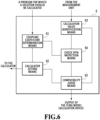
- Fig. 6 illustrates one example of the configuration of a solution quality retention unit 6 using the check spin.
- the Ising model calculation device includes, in addition to the configuration to calculate the Ising model as descried above, the solution quality retention unit 6 to use a check spin to retain the solution quality.
- the solution quality retention unit 6 may be configured by a calculation processing means such as a computer including a processor or a memory for example. As shown in Fig. 6 , the solution quality retention unit 6 has: a coupling coefficient determination means 61; a calculator setting means 62; a calculation value identification means 63; a check spin inspection means 64; and a compatibility judge means 65.
- the coupling coefficient determination means 61 determines a coupling coefficient depending on a problem for which a solution should be calculated and further determines, in order to examine the calculation precision, a coupling coefficient depending on a check problem for which the solution is known.
- the calculator setting means 62 sets, in the calculator 4, the coupling coefficient J ij obtained by combining a coupling coefficient depending on a problem for which a solution should be calculated determined by the coupling coefficient determination means 61 with a coupling coefficient corresponding to a check problem.
- the formula (2) and the formula (3) are set to have the coupling coefficient J ij based on this combination.
- Fig. 7 illustrates J ij set by the calculator setting means 62.
- the calculator setting means 62 sets the matrix J ij in which the upper-left part of 48 rows ⁇ 48 columns of the matrix constituting a part of the coupling coefficient is used as a coupling coefficient depending on the check problem and the lower-right part of 2000 rows ⁇ 2000 columns of the matrix is used as a coupling coefficient depending on a problem for which a solution should be calculated.
- the coupling coefficient of the check problem is calculated using the check spin of Fig. 2 .
- the coupling coefficient of the problem for which a solution should be calculated is calculated using the spins of Fig. 2 to calculate the inputted problem.
- the calculation value identification means 63 identifies, when the light pulse train is set in a stable state, a solution (calculation value) based on the measurement value obtained by the measurement unit 3.
- the identified solution includes both of a solution corresponding to a to-be-calculated problem and a solution corresponding to the check problem.
- the check spin inspection means 64 compares the solution of a part of the identified solution (calculation value) corresponding to the check problem with (a solution obtained by using the check spin) and an already-found solution of the check problem to inspect how much the former and the latter are matched.
- the compatibility judge means 65 judges, based on the result of inspecting the solution corresponding to the check spin, whether the resultant solution has a quality satisfying a quality reference or not. Whether the quality reference is satisfied or not is judged based on whether or not the number (probability) at which the solution corresponding to the check spin is matched with the known solution of the check problem is equal to or higher than the threshold value. When the judgement result shows that the quality reference is satisfied, then a part of the resultant solution corresponding to a to-be-calculated problem is adopted as a solution and is outputted as a solution by the Ising model calculation device. When the judgement result shows that the quality reference is not satisfied on the other hand, then the resultant solution is not adopted and the calculator setting means 62 is instructed again to set J ij .
- Fig. 8 illustrates the entire processing flow in the Ising model calculation device of this embodiment.
- Fig. 9 is a flow diagram illustrating a processing to calculate an Ising model.
- the Ising model calculation device of this embodiment has a configuration in which, upon receiving a problem for which a solution should be calculated, the coupling coefficient determination means 61 determines a coupling coefficient depending on a problem (S1) and determines a coupling coefficient depending on a check problem (S2).
- the coupling coefficient J ij obtained by combining the two coupling coefficients determined by the calculator setting means 62 is set in the calculator 4 (S3).
- the coupling coefficient J ij based on the combination is set in the calculator 4, then pump light is inputted to the PSA 2 of the Ising model calculation device, thereby starting the calculation based on the processing flow shown in Fig. 9 (S4).
- the coupling coefficient J ij based on the combination in S3 is set and pump light is firstly inputted to the PSA 2. Then, a weak noise light pulse train is generated (S11), and the generated noise light pulse train moves around within the ring resonator 1. A part of the noise light pulse train moving around within the ring resonator 1 is divided and the amplitude and the phase of the divided part are coherently measured by the measurement unit 3 (S12).
- the calculator 4 calculates a feedback value based on the matrix on which the coupling coefficient is mapped (S14).
- the external light pulse input unit 5 Upon receiving the calculation result by the calculator 4, the external light pulse input unit 5 inputs, to the ring resonator 1, an external light pulse having a phase and an amplitude depending on the calculation result to multiplex the external light pulse with the light pulse train within the ring resonator 1, thereby sending a feedback regarding the light pulse train (S15).
- the light pulse train after the feedback is inputted again to the PSA 2 and is amplified by pump light synchronized with the light pulse train (S16) and the resultant light pulse train moves again around within the ring resonator 1.
- the light pulse train moving again around within the ring resonator 1 is again subjected to the coherent measurement, the matrix-based calculation, and the feedback depending on the calculation result.
- the calculation value identification means 63 identifies the calculation result provided by the stable state (a value obtained by substituting 0 or ⁇ showing the phase state of the measurement result provided through the measurement unit 3 with the spin ⁇ state ( ⁇ 1) of the Ising model) (S5).
- the check spin inspection means 64 inspects whether any of the identified solutions matches with the solution of the check problem for which the solution corresponding to the check problem is already found (S6). As a result, the compatibility judge means 65 determines whether the quality reference is satisfied or not.
- the compatibility judge means 65 instructs the calculator setting means 62 to set a coupling coefficient again (S7:No).
- the coupling coefficient determination means 61 determines a coupling coefficient depending on a problem for which a solution should be calculated.
- the coupling coefficient determination means 61 adopts a check problem for which the solution is known as a check problem in order to examine the calculation precision, thereby determining a coupling coefficient depending on a check problem for which the solution is known.
- another check problem to examine the calculation precision may be used such as a problem having a bipartite structure (bipartite graph).
- the following section describe the configuration of the solution quality retention unit 6 using a check problem having a bipartite structure only with regard to parts different from those of the above configuration.
- Fig. 10 illustrates a problem having a bipartite structure.
- Fig. 11 illustrates the relation between the energy of the problem of the bipartite structure and the combined number.
- Fig. 12 illustrates the relation between the energy and the occurrence frequency of the solution obtained when the problem of the bipartite structure is calculated by the Ising model calculation device.
- the bipartite structure is one embodiment of a graph theory. Specifically, as shown in Fig. 10 , this is a graph structure in which, when arbitrary nodes divided to two subgraphs A and B (subsets) are connected by an edge, no edge exists between the same subgraphs.
- a problem is defined by the value of the weighting of the edge providing the connection between the respective nodes.
- the Ising model calculation device provides an association between the value of each node of the problem of the bipartite structure and any of the value "+1" or "-1" of each node of the Ising model and provides an association between the coupling strength of edges providing the connection between nodes and an Ising model coupling coefficient.
- the energy distribution of a problem having a target bipartite structure i.e., the distribution of the total of the values of the solution
- Fig. 11 a symmetrical distribution surrounding the energy "0" at the center.
- the occurrence frequencies of a solution having a predetermined energy by the Ising model calculation device is largely distributed at the maximum and minimum energy, resulting in being equal in the positive and negative directions to have "0" as a boundary.
- the Ising model calculation device is originally designed to calculate a solution at which the minimum energy is achieved.
- an incorrect solution is mainly caused by the phase shift of a light pulse to cause an inverted spin symbol (or an inverted symbol of a node value).
- the correctness of the calculation can be judged, based on the "0" energy of the solution to a problem of a bipartite structure as a boundary, by determining that the solution energy is lower than the "0" energy.
- a problem having a bipartite structure can be represented based on the following matrix (5).
- K means an arbitrary matrix and K t means a transposed matrix of K.
- C ij 0 ... 0 ⁇ ⁇ ⁇ 0 ... 0 K t K 0 ... 0 ⁇ ⁇ ⁇ 0 ... 0
- the problem of a bipartite structure represented by the subgraph shown in Fig. 10 can be represented by the following formula (6) where assuming that the subgraph A has the respective nodes A 1 , A 2 , A 3 ⁇ and the subgraph B has the respective nodes B 1 , B 2 , B 3 ⁇ , and the solution is fa 1 , fa 2 , fa 3 ⁇ fb 1 , fb 2 , fb 3 ⁇ .
- fa 1 fa 2 fa 3 ⁇ fb 1 fb 2 fb 3 ⁇ 0 ... 0 ⁇ ⁇ ⁇ 0 ... 0 K t K 0 ... 0 ⁇ ⁇ ⁇ 0 ... 0 A 1 A 2 A 3 ⁇ B 1 B 2 B 3 ⁇
- the respective elements of the above matrix (5) is determined by the coupling coefficient determination means 61 as a coupling coefficient depending on a check problem.
- the determined coupling coefficient may be set by the calculator setting means 62 as a coupling coefficient depending on a check problem as shown in Fig. 7 .
- the calculator setting means 62 sets a problem for which a solution should be calculated to the part of the coupling coefficient depending on the inputted graph problem of Fig. 7 .
- the check spin inspection means 64 identifies the energy of the solution of a part corresponding to the check problem of the solution identified by the calculation value identification means 63.
- the compatibility judge means 65 judges that the quality reference is satisfied when the energy of the solution identified by the check spin inspection means 64 is "0" or less (or lower than "0") as a threshold value in which the energy of the solution is "0".
- the check spin inspection means 64 is configured to identify the energy of the solution of the check problem instead of checking the matching with the solution of the check problem. Furthermore, the compatibility judge means 65 can judge that the quality reference is satisfied by determining that the energy of the solution of the check problem is "0" or less (or lower than "0") instead of determining that the probability of the matching of the solution of the check problem is equal to or higher than a threshold value. This can consequently provide, even when a problem having a bipartite structure is adopted as a check problem, a processing based on the processing flow shown in Fig. 8 .
- the Ising model calculation device was composed of the ring resonator 1, the PSA 2, the measurement unit 3, the calculator 4, and the external light pulse input unit 5.
- an example is merely shown for the relation shown in Fig. 2 between the check spin and the spin to solve the inputted problem and the relation shown in Fig. 7 between a coupling coefficient depending on a graph problem for the quality check and a coupling coefficient depending on the inputted graph problem (a problem for which a solution should be calculated).
- Which spin among all spins of the Ising model is used as a check spin is not particularly limited.
- An arbitrary number of spins at an arbitrary position can be adopted.
- the coupling coefficient of the matrix of the calculator 4 is also not limited to the coupling coefficient of the upper-left 48 rows ⁇ 48 columns as shown in Fig. 7 .
- an arbitrary number of coupling coefficients at an arbitrary position can be set as a coupling coefficient depending on the graph problem for the quality check and the rest can be set as a coupling coefficient depending on the inputted graph problem (a problem for which a solution should be calculated).
Landscapes
- Physics & Mathematics (AREA)
- Engineering & Computer Science (AREA)
- Theoretical Computer Science (AREA)
- Nonlinear Science (AREA)
- General Physics & Mathematics (AREA)
- Mathematical Physics (AREA)
- Optics & Photonics (AREA)
- Computing Systems (AREA)
- Artificial Intelligence (AREA)
- General Engineering & Computer Science (AREA)
- Data Mining & Analysis (AREA)
- Evolutionary Computation (AREA)
- Software Systems (AREA)
- Computational Mathematics (AREA)
- Pure & Applied Mathematics (AREA)
- Mathematical Optimization (AREA)
- Mathematical Analysis (AREA)
- Algebra (AREA)
- Probability & Statistics with Applications (AREA)
- Computational Linguistics (AREA)
- Optical Modulation, Optical Deflection, Nonlinear Optics, Optical Demodulation, Optical Logic Elements (AREA)
- Photometry And Measurement Of Optical Pulse Characteristics (AREA)
Claims (4)
- Isingmodellberechnungseinrichtung, die enthält:eine Resonatoreinheit, die aufweist:einen Ringresonator (1), der durch ringähnliche optische Fasern konfiguriert ist, um einer Vielzahl von Lichtimpulsen, die eine gleiche Oszillationsfrequenz haben, es zu ermöglichen, sich wiederholt in dem Ringresonator herum zu bewegen, undeinen phasensensitiven Verstärker (2), der in dem Ringresonator eingefügt ist, um:anfänglich jeden der Lichtimpulse basierend auf einem Pumplicht von einer Pumplichtquelle so zu erzeugen, dass der jeweilige Lichtimpuls einen Phasenzustand von 0 oder n hat, wobei der jeweilige Lichtimpuls den Phasenzustand von 0 hat, wenn der jeweilige Lichtimpuls eine Phase nahe bei 0 relativ zu einer Phase des Pumplichts hat, und der jeweilige Lichtimpuls den Phasenzustand von n hat, wenn der jeweilige Lichtimpuls die Phase nahe bei n relativ zu der Phase des Pumplichts hat, undeine optische parametrische Oszillation an dem jeweiligen Lichtimpuls für jeden der Lichtimpulse jedes Mal zu veranlassen, wenn der jeweilige Lichtimpuls wieder bei dem phasensensitiven Verstärker (2) ankommt, um den jeweiligen Lichtimpuls in dem Phasenzustand, den der jeweilige Lichtimpuls hat, wenn er dieses Mal bei dem phasensensitiven Verstärker ankommt, zu stabilisieren, wobei der phasensensitive Verstärker (2) konfiguriert ist, den jeweiligen Lichtimpuls bei dem Phasenzustand, den der jeweilige Lichtimpuls hat, wenn er dieses Mal ankommt, zu stabilisieren und den jeweiligen Lichtimpuls dadurch zu verstärken, dass jedes Mal, wenn der jeweilige Lichtimpuls wieder bei dem phasensensitiven Verstärker (2) ankommt, eine jeweilige entartete Welle als der jeweilige verstärkte Lichtimpuls ausgegeben wird, wobei die jeweilige entartete Welle durch Überlagern des jeweiligen empfangenen Lichtimpulses, der als jeweiliges Signallicht fungiert, mit jeweiligem Leerlauflicht erhalten wird, wobei der phasensensitive Verstärker (2) konfiguriert ist, das jeweilige Leerlauflicht basierend auf dem Pumplicht von der Pumplichtquelle zu erzeugen, und das jeweilige Leerlauflicht eine Phase von 0 oder n relativ zu der Phase des Pumplichts hat, und das Pumplicht vollständig phasenangepasst an das jeweilige Signallicht ist, wobei das jeweilige Leerlauflicht als eine Phasenkonjugierte des jeweiligen Signallichts, das an dem phasensensitiven Verstärker (2) empfangen wird, fungiert, wobei die Oszillationsfrequenz des jeweiligen Signallichts zu einer Frequenz des jeweiligen Leerlauflichts passt; undeine Feedbackkonfiguration, die aufweist:eine Lichtimpulsmesseinheit (3) zum Teilen von jedem der Vielzahl der Lichtimpulse, die innerhalb des Ringresonators propagieren, in einen ersten Anteil, der fortfährt, innerhalb des Ringresonators zu propagieren, und einen zweiten Anteil, der aus dem Ringresonator ausgekoppelt wird, und zum Messen der Phase und der Amplitude des zweiten Anteils des jeweiligen Lichtimpulses, die die Phase und die Amplitude des jeweiligen Lichtimpulses repräsentieren, in jeder Runde, den sich die Lichtimpulse in dem Ringresonator herum bewegen,einen Interaktionsberechner (4) zum Berechnen eines jeweiligen Kopplungssignals fi(n) für jeden der Lichtimpulse und jede Runde der Lichtimpulse in dem Ringresonator basierend auf den Phasen und Amplituden der Vielzahl von Lichtimpulsen, die durch die Lichtimpulsmesseinheit für die jeweilige Runde gemessen werden, und kombinierte Isingmodellkopplungskoeffizienten, wobei für jeden Lichtimpuls i der Lichtimpulse das jeweilige Kopplungssignal fi(n) als
 berechnet wird, wobei ein Vorzeichen von cj(n) den Phasenzustand eines Lichtimpulses j der Lichtimpulse, der in der Runde n des Lichtimpulses j in dem Ringresonator gemessen wird, bezeichnet, ein Absolutwert von cj(n) eine Amplitude des Lichtimpulses j der Lichtimpulse, die in der Runde n des Lichtimpulses j in dem Ringresonator gemessen wird, bezeichnet, und Jij den kombinierten Isingmodellkopplungskoeffizienten zwischen dem Impuls i und dem Impuls j bezeichnet, undeine externe Lichtimpulseingabeeinheit (5), um für jeden der Lichtimpulse i und jede Runde n der Lichtimpulse:einen jeweiligen externen Lichtimpuls mit der Oszillationsfrequenz zu erzeugen, wobei die Amplitude und die Phase des jeweiligen externen Lichtimpulses proportional zu dem jeweiligen Kopplungssignal fi(n), das durch den Interaktionsberechner berechnet wird, sind, undden jeweiligen externen Lichtimpulses mit dem jeweiligen Lichtimpuls in dem Ringresonator zu überlagern, sodass die Phase und die Amplitude ci'(n) des Lichtimpulses i, der von dem Überlagern resultiert, ci(n) + Kfi (n) sind, wobei K ein Kopplungsverhältnis ist, das Vorzeichen von ci'(n) den Phasenzustand des Lichtimpulses i, der sich aus dem Überlagern ergibt, bezeichnet, ein absoluter Wert von ci'(n) die Amplitude des Lichtimpulses i, der sich aus dem Überlagern ergibt, bezeichnet, das Vorzeichen von ci(n) den Phasenzustand des Lichtimpulses i gemessen in der Runde n vor dem Überlagern bezeichnet, und der absolute Wert von ci(n) die Amplitude des Lichtimpulses i gemessen in der Runde n vor dem Überlagern bezeichnet, wobeidie Lichtimpulsmesseinheit (3) konfiguriert ist, das Aufteilen von jedem der Vielzahl der Lichtimpulse an einem ersten Ort in dem Ringresonator durchzuführen, wobei der erste Ort hinter dem phasensensitiven Verstärker in einer Richtung der Propagation der Lichtimpulse ist, und der erste Ort vor einem zweiten Ort in der Richtung der Propagation der Lichtimpulse ist, wobei die externe Lichtimpulseingabeeinheit (5) konfiguriert ist, den jeweiligen externen Lichtimpuls mit dem jeweiligen Lichtimpuls an dem zweiten Ort zu überlagern;die Lichtimpulsmesseinheit (3) konfiguriert ist, in einem Prozess des Wiederholens einer Feedbackschleifensteuerung, der durch die Lichtimpulsmesseinheit (3), den Interaktionsberechner (4) und die externe Lichtimpulseingabeeinheit (5) konfiguriert ist, die Phasenzustände der Vielzahl von Lichtimpulsen, die gemessen werden, nachdem davon ausgegangen wird, dass die Vielzahl der Lichtimpulse einen stabilen Zustand nach wiederholtem Verstärken und Feedback erreicht haben, in Spins eines kombinierten Isingmodells zu konvertieren, um die Werte der Spins des kombinierten Isingmodells zu erhalten,die kombinierten Isingmodellkopplungskoeffizienten das kombinierte Isingmodel definieren, wobei jeder der Lichtimpulse einem jeweiligen der Orte des kombinierten Isingmodells entspricht; für jeden der Orte des kombinierten Isingmodells der Spinzustand des jeweiligen Orts dem Phasenzustand des Lichtimpulses, der dem jeweiligen Ort entspricht, entspricht; der Phasenzustand von 0 oder n den Werten von 1 bzw. -1 der Spins des kombinierten Isingmodells entspricht;gekennzeichnet durcheine Prüfspineinführeinheit (6) zum Verwenden eines Teils der Vielzahl von Lichtimpulsen, um ein Prüfproblem zum Auswählen einer Lösung eines Hauptproblems, für das die Lösung berechnet werden soll, zu lösen, wobei das Hauptproblem einem ersten Isingmodell mit einer ersten Anzahl von Orten entspricht, das Prüfproblem einem zweiten Isingmodell mit einer zweiten Anzahl von Orten entspricht, das erste Isingmodell durch erste Isingmodellkopplungskoeffizienten definiert ist, das zweite Isingmodell durch zweite Isingmodellkopplungskoeffizienten definiert ist, eine Lösung des Prüfproblems im Voraus bekannt ist, eine Anzahl der Orte des kombinierten Isingmodells eine Summe der ersten Anzahl von Orten des ersten Isingmodells und der zweiten Anzahl von Orten des zweiten Isingmodells ist, und die Orte des kombinierten Isingmodells Gitterpunkte sind, in denen die Spins des kombinierten Isingmodells angeordnet sind;wobei die Prüfspineinführeinheit (6) konfiguriert ist, um:die ersten Isingmodellkopplungskoeffizienten, die dem Hauptproblem entsprechen, mit den zweiten Isingmodellkopplungskoeffizienten, die dem Prüfproblem entsprechen, zu kombinieren, um die Kopplungskoeffizienten des kombinierten Isingmodells, die verwendet werden, um die Kopplungssignale zu berechnen, zu erhalten, wobeijeder der Lichtimpulse entweder einem Ort des ersten Isingmodells oder einem Ort des zweiten Isingmodells entspricht;für jeden der Orte des ersten Isingmodells der Spinzustand des jeweiligen Orts dem Phasenzustand des Lichtimpulses, der dem jeweiligen Ort entspricht, entspricht;für jeden der Orte des zweiten Isingmodells der Spinzustand des jeweiligen Orts dem Phasenzustand des Lichtimpulses, der dem jeweiligen Ort entspricht, entspricht; für jeden Wert k und jeden Wert l der Kopplungskoeffizient des kombinierten Isingmodells Jkl = 0, wenn ein Lichtimpuls k der Lichtimpulse einem Ort des ersten Isingmodells entspricht und ein Lichtimpuls l der Lichtimpulse einem Ort des zweiten Isingmodells entspricht,für jeden Wert von r und jeden Wert von s der Kopplungskoeffizient Jrs des kombinierten Isingmodells gleich dem Kopplungskoeffizienten zwischen dem Ort des ersten Isingmodells, der dem Lichtimpuls r entspricht, und dem Ort des ersten Isingmodells, der dem Lichtimpuls s entspricht, ist, wenn ein Lichtimpuls r der Lichtimpulse einem Ort des ersten Isingmodells entspricht und ein Lichtimpuls s der Lichtimpulse einem Ort des ersten Isingmodells entspricht,für jeden Wert t und jeden Wert u der Kopplungskoeffizient Jtu des kombinierten Isingmodells gleich dem Kopplungskoeffizienten zwischen dem Ort des zweiten Isingmodells, der dem Lichtimpuls t entspricht, und dem Ort des zweiten Isingmodells, der dem Lichtimpuls u entspricht, ist, wenn ein Lichtimpuls t der Lichtimpulse einem Ort des zweiten Isingmodells entspricht und ein Lichtimpuls u der Lichtimpulse einem Ort des zweiten Isingmodells entspricht,zu beurteilen, nachdem angenommen wird, dass die Vielzahl der Lichtimpulse einen stabilen Zustand nach wiederholtem Verstärken und Feedback erreicht haben, ob eine Wahrscheinlichkeit, mit der eine berechnete Lösung des Prüfproblems mit der bekannten Lösung zusammenfällt oder nicht, gleich groß oder größer als ein Schwellenwert ist, wobei die Spinzustände, die den Phasenzuständen der Lichtimpulse, die den Orten des zweiten Isingmodells entsprechen, die von den Phasen der Lichtimpulse, die den Orten des zweiten Isingmodells entsprechen, die durch die Lichtimpulsmesseinheit (3) gemessen werden, als die berechnete Lösung des Prüfproblems betrachtet werden;wenn die Wahrscheinlichkeit gleich oder größer als der Schwellenwert ist, die Phasenzustände der Lichtimpulse, die verschieden von den Lichtimpulsen, die den Orten des zweiten Isingmodells entsprechen, als die Lösung des Hauptproblems auszugeben; undwenn die Wahrscheinlichkeit niedriger als der Schwellenwert ist, die Kopplungskoeffizienten des kombinierten Isingmodells wieder als die Kopplungskoeffizienten des kombinierten Isingmodells einzustellen und zu veranlassen, dass die Isingmodellberechnungseinrichtung das anfängliche Erzeugen der Lichtimpulse, das Veranlassen der parametrischen Oszillation, das Aufteilen von jedem der Vielzahl der Lichtimpulse, das Messen der Phasen und Amplituden der Vielzahl von Lichtimpulsen, das Berechnen der Kopplungsignale, das Erzeugen der externen Lichtimpulse, das Überlagern der externen Lichtimpulse, das Beurteilen und, abhängig von einem Ergebnis des wiederholten Beurteilens, das Ausgeben oder das Einstellen der kombinierten Isingmodellkopplungskoeffizienten mit dem Veranlassen der Isingmodellberechnungseinheit, zu wiederholen, zu veranlassen.
 - Isingmodellberechnungseinrichtung nach Anspruch 1, wobei
die Kopplungssignale f1(n) bis fN(n) unter Verwendung der folgenden Formel 1 berechnet werden,
- Isingmodellberechnungseinrichtung nach einem der Ansprüche 1 bis 2, wobei das Prüfproblem ein Problem mit einer Bipartitstruktur ist.
- Isingmodellberechnungseinrichtung nach einem der Ansprüche 1 bis 3, ferner mit der Pumplichtquelle, die konfiguriert ist, das Pumplicht zu emittieren.
Applications Claiming Priority (2)
| Application Number | Priority Date | Filing Date | Title |
|---|---|---|---|
| JP2017202987 | 2017-10-19 | ||
| PCT/JP2018/038994 WO2019078354A1 (ja) | 2017-10-19 | 2018-10-19 | イジングモデルの計算装置 |
Publications (3)
| Publication Number | Publication Date |
|---|---|
| EP3699685A1 EP3699685A1 (de) | 2020-08-26 |
| EP3699685A4 EP3699685A4 (de) | 2021-07-28 |
| EP3699685B1 true EP3699685B1 (de) | 2023-09-27 |
Family
ID=66173298
Family Applications (1)
| Application Number | Title | Priority Date | Filing Date |
|---|---|---|---|
| EP18867887.4A Active EP3699685B1 (de) | 2017-10-19 | 2018-10-19 | Ising-modellberechnungsvorrichtung |
Country Status (5)
| Country | Link |
|---|---|
| US (1) | US11385522B2 (de) |
| EP (1) | EP3699685B1 (de) |
| JP (1) | JP6734997B2 (de) |
| CN (1) | CN111065963B (de) |
| WO (1) | WO2019078354A1 (de) |
Families Citing this family (11)
| Publication number | Priority date | Publication date | Assignee | Title |
|---|---|---|---|---|
| JP6734997B2 (ja) * | 2017-10-19 | 2020-08-05 | 日本電信電話株式会社 | イジングモデルの計算装置 |
| JP6992620B2 (ja) * | 2018-03-14 | 2022-01-13 | 日本電信電話株式会社 | 光信号送信器 |
| JP7295460B2 (ja) | 2019-08-28 | 2023-06-21 | 日本電信電話株式会社 | 位相同期方法および位相同期装置 |
| CN112486898B (zh) * | 2019-09-11 | 2023-02-10 | 华为技术有限公司 | 一种光计算设备以及计算方法 |
| CN112486244B (zh) * | 2019-09-11 | 2024-07-19 | 华为技术有限公司 | 一种光计算设备以及光信号处理方法 |
| CN112883534B (zh) * | 2019-11-30 | 2025-09-16 | 华为技术有限公司 | 一种光计算设备以及光信号处理方法 |
| JP7348578B2 (ja) * | 2020-04-23 | 2023-09-21 | 日本電信電話株式会社 | イジングモデルの計算装置 |
| CN114692381B (zh) * | 2020-12-31 | 2024-12-24 | 中国科学院半导体研究所 | 相干伊辛机及组合优化问题的解决方法 |
| CN113190080B (zh) * | 2021-02-01 | 2023-06-13 | 中山大学 | 一种用于优化光学伊辛机系统的方法 |
| EP4040340A1 (de) * | 2021-02-05 | 2022-08-10 | Microsoft Technology Licensing, LLC | Hardware-solver-architektur |
| US20240394328A1 (en) * | 2021-08-25 | 2024-11-28 | Nippon Telegraph And Telephone Corporation | Ising Model Calculator |
Family Cites Families (8)
| Publication number | Priority date | Publication date | Assignee | Title |
|---|---|---|---|---|
| JP2010054938A (ja) * | 2008-08-29 | 2010-03-11 | Toshiba Corp | 量子シミュレータ、量子計算機および方法 |
| JP5354233B2 (ja) * | 2011-03-01 | 2013-11-27 | 大学共同利用機関法人情報・システム研究機構 | イジングモデルの量子計算装置及びイジングモデルの量子計算方法 |
| JP6300049B2 (ja) * | 2013-07-09 | 2018-03-28 | ザ ボード オブ トラスティーズ オブ ザ レランド スタンフォード ジュニア ユニバーシティー | 光パラメトリック発振器のネットワークを使用する計算 |
| JP6260896B2 (ja) * | 2013-12-09 | 2018-01-17 | 大学共同利用機関法人情報・システム研究機構 | イジングモデルの量子計算装置 |
| US10140580B2 (en) | 2014-04-11 | 2018-11-27 | Inter-University Research Institute Corporation, Research Organization of Information and systems | Quantum computing device for Ising model, quantum parallel computing device for Ising model, and quantum computing method for Ising model |
| CA2997013C (en) * | 2015-09-15 | 2020-04-07 | Nippon Telegraph And Telephone Corporation | Ising model quantum computation device |
| US10069573B2 (en) * | 2016-03-10 | 2018-09-04 | Raytheon Bbn Technologies Corp. | Optical ising-model solver using quantum annealing |
| JP6734997B2 (ja) * | 2017-10-19 | 2020-08-05 | 日本電信電話株式会社 | イジングモデルの計算装置 |
-
2018
- 2018-10-19 JP JP2019548827A patent/JP6734997B2/ja active Active
- 2018-10-19 EP EP18867887.4A patent/EP3699685B1/de active Active
- 2018-10-19 US US16/634,650 patent/US11385522B2/en active Active
- 2018-10-19 WO PCT/JP2018/038994 patent/WO2019078354A1/ja not_active Ceased
- 2018-10-19 CN CN201880055309.7A patent/CN111065963B/zh active Active
Also Published As
| Publication number | Publication date |
|---|---|
| JP6734997B2 (ja) | 2020-08-05 |
| CN111065963A (zh) | 2020-04-24 |
| EP3699685A1 (de) | 2020-08-26 |
| CN111065963B (zh) | 2022-08-02 |
| EP3699685A4 (de) | 2021-07-28 |
| WO2019078354A1 (ja) | 2019-04-25 |
| US11385522B2 (en) | 2022-07-12 |
| JPWO2019078354A1 (ja) | 2020-05-28 |
| US20210088873A1 (en) | 2021-03-25 |
Similar Documents
| Publication | Publication Date | Title |
|---|---|---|
| EP3699685B1 (de) | Ising-modellberechnungsvorrichtung | |
| Hillesheim et al. | A multichannel, frequency-modulated, tunable Doppler backscattering and reflectometry system | |
| JP6533544B2 (ja) | イジングモデルの計算装置 | |
| US11280668B2 (en) | Distributed optical fiber vibration measurement device and distributed optical fiber vibration measurement method | |
| EP3699721B1 (de) | Vorrichtung zur berechnung eines potts-modells | |
| CN103292918A (zh) | 相位变化测量系统 | |
| Zong et al. | Oscillation mode variability in evolved compact pulsators from Kepler photometry. II. Comparison of modulation patterns between raw and corrected flux | |
| JP6220764B2 (ja) | 光ファイバ特性解析装置および光ファイバ特性解析方法 | |
| JP6980185B2 (ja) | イジングモデルの計算装置 | |
| US20230176607A1 (en) | Ising Model Calculation Device | |
| US20210018372A1 (en) | Optical Spectral Line Width Calculation Method, Device, and Program | |
| JP6581613B2 (ja) | イジングモデルの計算装置 | |
| Hachtel et al. | An undergraduate measurement of radiative broadening in atomic vapor | |
| Kumar et al. | Accounting for the known unknowns: A parametric framework to incorporate systematic waveform errors in gravitational-wave parameter estimation | |
| Jamet et al. | Emission and detection of ultrahigh frequency gravitational waves from highly eccentric orbits of compact binary systems | |
| JP2018147226A (ja) | イジングモデルの計算装置 | |
| EP4212834A1 (de) | Vibrationserkennungsvorrichtung und vibrationserkennungsverfahren | |
| JP7018620B2 (ja) | イジングモデルの計算装置 | |
| Morton et al. | SURF Interim Reports | |
| Samoilenko et al. | Photon number measurement using heterodyne method for a detector’s quantum efficiency determination based on spontaneous parametric down-conversion | |
| Riebesehl | Digital Signal Processing Techniques for Noise Characterization of Lasers and Optical Frequency Combs | |
| Vetere | IMPROVED ATOM COUNTING USING SQUEEZED LIGHT FOR ATOM INTERFEROMETRY APPLICATIONS | |
| Spaeth et al. | Precise radial velocities of giant stars | |
| Jiang et al. | Determination of the sign of the population difference in a two-level system by frequency-modulation spectroscopy | |
| Caracas Núñez | Theoretical & experimental entangled two-photon absorption in cesium atoms |
Legal Events
| Date | Code | Title | Description |
|---|---|---|---|
| STAA | Information on the status of an ep patent application or granted ep patent |
Free format text: STATUS: THE INTERNATIONAL PUBLICATION HAS BEEN MADE |
|
| PUAI | Public reference made under article 153(3) epc to a published international application that has entered the european phase |
Free format text: ORIGINAL CODE: 0009012 |
|
| STAA | Information on the status of an ep patent application or granted ep patent |
Free format text: STATUS: REQUEST FOR EXAMINATION WAS MADE |
|
| 17P | Request for examination filed |
Effective date: 20200206 |
|
| AK | Designated contracting states |
Kind code of ref document: A1 Designated state(s): AL AT BE BG CH CY CZ DE DK EE ES FI FR GB GR HR HU IE IS IT LI LT LU LV MC MK MT NL NO PL PT RO RS SE SI SK SM TR |
|
| AX | Request for extension of the european patent |
Extension state: BA ME |
|
| DAV | Request for validation of the european patent (deleted) | ||
| DAX | Request for extension of the european patent (deleted) | ||
| A4 | Supplementary search report drawn up and despatched |
Effective date: 20210628 |
|
| RIC1 | Information provided on ipc code assigned before grant |
Ipc: G06N 7/00 20060101AFI20210622BHEP Ipc: G06N 5/00 20060101ALI20210622BHEP Ipc: G06E 3/00 20060101ALI20210622BHEP Ipc: G02F 1/39 20060101ALI20210622BHEP Ipc: G02F 3/00 20060101ALI20210622BHEP |
|
| STAA | Information on the status of an ep patent application or granted ep patent |
Free format text: STATUS: EXAMINATION IS IN PROGRESS |
|
| 17Q | First examination report despatched |
Effective date: 20220310 |
|
| REG | Reference to a national code |
Ref country code: DE Free format text: PREVIOUS MAIN CLASS: G02F0003000000 Ref country code: DE Ref legal event code: R079 Ref document number: 602018058427 Country of ref document: DE Free format text: PREVIOUS MAIN CLASS: G02F0003000000 Ipc: G06E0003000000 |
|
| GRAP | Despatch of communication of intention to grant a patent |
Free format text: ORIGINAL CODE: EPIDOSNIGR1 |
|
| STAA | Information on the status of an ep patent application or granted ep patent |
Free format text: STATUS: GRANT OF PATENT IS INTENDED |
|
| RIC1 | Information provided on ipc code assigned before grant |
Ipc: G06N 7/01 20230101ALI20230424BHEP Ipc: G06N 5/01 20230101ALI20230424BHEP Ipc: G02F 1/39 20060101ALI20230424BHEP Ipc: G06E 3/00 20060101AFI20230424BHEP |
|
| INTG | Intention to grant announced |
Effective date: 20230517 |
|
| GRAS | Grant fee paid |
Free format text: ORIGINAL CODE: EPIDOSNIGR3 |
|
| GRAA | (expected) grant |
Free format text: ORIGINAL CODE: 0009210 |
|
| STAA | Information on the status of an ep patent application or granted ep patent |
Free format text: STATUS: THE PATENT HAS BEEN GRANTED |
|
| AK | Designated contracting states |
Kind code of ref document: B1 Designated state(s): AL AT BE BG CH CY CZ DE DK EE ES FI FR GB GR HR HU IE IS IT LI LT LU LV MC MK MT NL NO PL PT RO RS SE SI SK SM TR |
|
| REG | Reference to a national code |
Ref country code: GB Ref legal event code: FG4D |
|
| REG | Reference to a national code |
Ref country code: CH Ref legal event code: EP |
|
| REG | Reference to a national code |
Ref country code: DE Ref legal event code: R096 Ref document number: 602018058427 Country of ref document: DE |
|
| REG | Reference to a national code |
Ref country code: IE Ref legal event code: FG4D |
|
| REG | Reference to a national code |
Ref country code: LT Ref legal event code: MG9D |
|
| PG25 | Lapsed in a contracting state [announced via postgrant information from national office to epo] |
Ref country code: GR Free format text: LAPSE BECAUSE OF FAILURE TO SUBMIT A TRANSLATION OF THE DESCRIPTION OR TO PAY THE FEE WITHIN THE PRESCRIBED TIME-LIMIT Effective date: 20231228 |
|
| PG25 | Lapsed in a contracting state [announced via postgrant information from national office to epo] |
Ref country code: SE Free format text: LAPSE BECAUSE OF FAILURE TO SUBMIT A TRANSLATION OF THE DESCRIPTION OR TO PAY THE FEE WITHIN THE PRESCRIBED TIME-LIMIT Effective date: 20230927 Ref country code: RS Free format text: LAPSE BECAUSE OF FAILURE TO SUBMIT A TRANSLATION OF THE DESCRIPTION OR TO PAY THE FEE WITHIN THE PRESCRIBED TIME-LIMIT Effective date: 20230927 Ref country code: NO Free format text: LAPSE BECAUSE OF FAILURE TO SUBMIT A TRANSLATION OF THE DESCRIPTION OR TO PAY THE FEE WITHIN THE PRESCRIBED TIME-LIMIT Effective date: 20231227 Ref country code: LV Free format text: LAPSE BECAUSE OF FAILURE TO SUBMIT A TRANSLATION OF THE DESCRIPTION OR TO PAY THE FEE WITHIN THE PRESCRIBED TIME-LIMIT Effective date: 20230927 Ref country code: LT Free format text: LAPSE BECAUSE OF FAILURE TO SUBMIT A TRANSLATION OF THE DESCRIPTION OR TO PAY THE FEE WITHIN THE PRESCRIBED TIME-LIMIT Effective date: 20230927 Ref country code: HR Free format text: LAPSE BECAUSE OF FAILURE TO SUBMIT A TRANSLATION OF THE DESCRIPTION OR TO PAY THE FEE WITHIN THE PRESCRIBED TIME-LIMIT Effective date: 20230927 Ref country code: GR Free format text: LAPSE BECAUSE OF FAILURE TO SUBMIT A TRANSLATION OF THE DESCRIPTION OR TO PAY THE FEE WITHIN THE PRESCRIBED TIME-LIMIT Effective date: 20231228 Ref country code: FI Free format text: LAPSE BECAUSE OF FAILURE TO SUBMIT A TRANSLATION OF THE DESCRIPTION OR TO PAY THE FEE WITHIN THE PRESCRIBED TIME-LIMIT Effective date: 20230927 |
|
| REG | Reference to a national code |
Ref country code: NL Ref legal event code: MP Effective date: 20230927 |
|
| REG | Reference to a national code |
Ref country code: AT Ref legal event code: MK05 Ref document number: 1616036 Country of ref document: AT Kind code of ref document: T Effective date: 20230927 |
|
| PG25 | Lapsed in a contracting state [announced via postgrant information from national office to epo] |
Ref country code: NL Free format text: LAPSE BECAUSE OF FAILURE TO SUBMIT A TRANSLATION OF THE DESCRIPTION OR TO PAY THE FEE WITHIN THE PRESCRIBED TIME-LIMIT Effective date: 20230927 |
|
| PG25 | Lapsed in a contracting state [announced via postgrant information from national office to epo] |
Ref country code: IS Free format text: LAPSE BECAUSE OF FAILURE TO SUBMIT A TRANSLATION OF THE DESCRIPTION OR TO PAY THE FEE WITHIN THE PRESCRIBED TIME-LIMIT Effective date: 20240127 |
|
| PG25 | Lapsed in a contracting state [announced via postgrant information from national office to epo] |
Ref country code: AT Free format text: LAPSE BECAUSE OF FAILURE TO SUBMIT A TRANSLATION OF THE DESCRIPTION OR TO PAY THE FEE WITHIN THE PRESCRIBED TIME-LIMIT Effective date: 20230927 |
|
| PG25 | Lapsed in a contracting state [announced via postgrant information from national office to epo] |
Ref country code: ES Free format text: LAPSE BECAUSE OF FAILURE TO SUBMIT A TRANSLATION OF THE DESCRIPTION OR TO PAY THE FEE WITHIN THE PRESCRIBED TIME-LIMIT Effective date: 20230927 |
|
| PG25 | Lapsed in a contracting state [announced via postgrant information from national office to epo] |
Ref country code: SM Free format text: LAPSE BECAUSE OF FAILURE TO SUBMIT A TRANSLATION OF THE DESCRIPTION OR TO PAY THE FEE WITHIN THE PRESCRIBED TIME-LIMIT Effective date: 20230927 Ref country code: RO Free format text: LAPSE BECAUSE OF FAILURE TO SUBMIT A TRANSLATION OF THE DESCRIPTION OR TO PAY THE FEE WITHIN THE PRESCRIBED TIME-LIMIT Effective date: 20230927 Ref country code: IS Free format text: LAPSE BECAUSE OF FAILURE TO SUBMIT A TRANSLATION OF THE DESCRIPTION OR TO PAY THE FEE WITHIN THE PRESCRIBED TIME-LIMIT Effective date: 20240127 Ref country code: ES Free format text: LAPSE BECAUSE OF FAILURE TO SUBMIT A TRANSLATION OF THE DESCRIPTION OR TO PAY THE FEE WITHIN THE PRESCRIBED TIME-LIMIT Effective date: 20230927 Ref country code: EE Free format text: LAPSE BECAUSE OF FAILURE TO SUBMIT A TRANSLATION OF THE DESCRIPTION OR TO PAY THE FEE WITHIN THE PRESCRIBED TIME-LIMIT Effective date: 20230927 Ref country code: CZ Free format text: LAPSE BECAUSE OF FAILURE TO SUBMIT A TRANSLATION OF THE DESCRIPTION OR TO PAY THE FEE WITHIN THE PRESCRIBED TIME-LIMIT Effective date: 20230927 Ref country code: AT Free format text: LAPSE BECAUSE OF FAILURE TO SUBMIT A TRANSLATION OF THE DESCRIPTION OR TO PAY THE FEE WITHIN THE PRESCRIBED TIME-LIMIT Effective date: 20230927 Ref country code: SK Free format text: LAPSE BECAUSE OF FAILURE TO SUBMIT A TRANSLATION OF THE DESCRIPTION OR TO PAY THE FEE WITHIN THE PRESCRIBED TIME-LIMIT Effective date: 20230927 Ref country code: PT Free format text: LAPSE BECAUSE OF FAILURE TO SUBMIT A TRANSLATION OF THE DESCRIPTION OR TO PAY THE FEE WITHIN THE PRESCRIBED TIME-LIMIT Effective date: 20240129 |
|
| PG25 | Lapsed in a contracting state [announced via postgrant information from national office to epo] |
Ref country code: PL Free format text: LAPSE BECAUSE OF FAILURE TO SUBMIT A TRANSLATION OF THE DESCRIPTION OR TO PAY THE FEE WITHIN THE PRESCRIBED TIME-LIMIT Effective date: 20230927 Ref country code: IT Free format text: LAPSE BECAUSE OF FAILURE TO SUBMIT A TRANSLATION OF THE DESCRIPTION OR TO PAY THE FEE WITHIN THE PRESCRIBED TIME-LIMIT Effective date: 20230927 |
|
| REG | Reference to a national code |
Ref country code: CH Ref legal event code: PL |
|
| REG | Reference to a national code |
Ref country code: BE Ref legal event code: MM Effective date: 20231031 |
|
| PG25 | Lapsed in a contracting state [announced via postgrant information from national office to epo] |
Ref country code: LU Free format text: LAPSE BECAUSE OF NON-PAYMENT OF DUE FEES Effective date: 20231019 |
|
| PG25 | Lapsed in a contracting state [announced via postgrant information from national office to epo] |
Ref country code: LU Free format text: LAPSE BECAUSE OF NON-PAYMENT OF DUE FEES Effective date: 20231019 |
|
| REG | Reference to a national code |
Ref country code: DE Ref legal event code: R097 Ref document number: 602018058427 Country of ref document: DE |
|
| PG25 | Lapsed in a contracting state [announced via postgrant information from national office to epo] |
Ref country code: MC Free format text: LAPSE BECAUSE OF FAILURE TO SUBMIT A TRANSLATION OF THE DESCRIPTION OR TO PAY THE FEE WITHIN THE PRESCRIBED TIME-LIMIT Effective date: 20230927 |
|
| PG25 | Lapsed in a contracting state [announced via postgrant information from national office to epo] |
Ref country code: DK Free format text: LAPSE BECAUSE OF FAILURE TO SUBMIT A TRANSLATION OF THE DESCRIPTION OR TO PAY THE FEE WITHIN THE PRESCRIBED TIME-LIMIT Effective date: 20230927 |
|
| PG25 | Lapsed in a contracting state [announced via postgrant information from national office to epo] |
Ref country code: CH Free format text: LAPSE BECAUSE OF NON-PAYMENT OF DUE FEES Effective date: 20231031 |
|
| PG25 | Lapsed in a contracting state [announced via postgrant information from national office to epo] |
Ref country code: MC Free format text: LAPSE BECAUSE OF FAILURE TO SUBMIT A TRANSLATION OF THE DESCRIPTION OR TO PAY THE FEE WITHIN THE PRESCRIBED TIME-LIMIT Effective date: 20230927 Ref country code: DK Free format text: LAPSE BECAUSE OF FAILURE TO SUBMIT A TRANSLATION OF THE DESCRIPTION OR TO PAY THE FEE WITHIN THE PRESCRIBED TIME-LIMIT Effective date: 20230927 Ref country code: CH Free format text: LAPSE BECAUSE OF NON-PAYMENT OF DUE FEES Effective date: 20231031 |
|
| PLBE | No opposition filed within time limit |
Free format text: ORIGINAL CODE: 0009261 |
|
| STAA | Information on the status of an ep patent application or granted ep patent |
Free format text: STATUS: NO OPPOSITION FILED WITHIN TIME LIMIT |
|
| PG25 | Lapsed in a contracting state [announced via postgrant information from national office to epo] |
Ref country code: BE Free format text: LAPSE BECAUSE OF NON-PAYMENT OF DUE FEES Effective date: 20231031 |
|
| 26N | No opposition filed |
Effective date: 20240628 |
|
| PG25 | Lapsed in a contracting state [announced via postgrant information from national office to epo] |
Ref country code: IE Free format text: LAPSE BECAUSE OF NON-PAYMENT OF DUE FEES Effective date: 20231019 |
|
| PG25 | Lapsed in a contracting state [announced via postgrant information from national office to epo] |
Ref country code: SI Free format text: LAPSE BECAUSE OF FAILURE TO SUBMIT A TRANSLATION OF THE DESCRIPTION OR TO PAY THE FEE WITHIN THE PRESCRIBED TIME-LIMIT Effective date: 20230927 |
|
| PG25 | Lapsed in a contracting state [announced via postgrant information from national office to epo] |
Ref country code: SI Free format text: LAPSE BECAUSE OF FAILURE TO SUBMIT A TRANSLATION OF THE DESCRIPTION OR TO PAY THE FEE WITHIN THE PRESCRIBED TIME-LIMIT Effective date: 20230927 Ref country code: IE Free format text: LAPSE BECAUSE OF NON-PAYMENT OF DUE FEES Effective date: 20231019 |
|
| PG25 | Lapsed in a contracting state [announced via postgrant information from national office to epo] |
Ref country code: BG Free format text: LAPSE BECAUSE OF FAILURE TO SUBMIT A TRANSLATION OF THE DESCRIPTION OR TO PAY THE FEE WITHIN THE PRESCRIBED TIME-LIMIT Effective date: 20230927 |
|
| PG25 | Lapsed in a contracting state [announced via postgrant information from national office to epo] |
Ref country code: BG Free format text: LAPSE BECAUSE OF FAILURE TO SUBMIT A TRANSLATION OF THE DESCRIPTION OR TO PAY THE FEE WITHIN THE PRESCRIBED TIME-LIMIT Effective date: 20230927 |
|
| PG25 | Lapsed in a contracting state [announced via postgrant information from national office to epo] |
Ref country code: CY Free format text: LAPSE BECAUSE OF FAILURE TO SUBMIT A TRANSLATION OF THE DESCRIPTION OR TO PAY THE FEE WITHIN THE PRESCRIBED TIME-LIMIT; INVALID AB INITIO Effective date: 20181019 |
|
| PG25 | Lapsed in a contracting state [announced via postgrant information from national office to epo] |
Ref country code: HU Free format text: LAPSE BECAUSE OF FAILURE TO SUBMIT A TRANSLATION OF THE DESCRIPTION OR TO PAY THE FEE WITHIN THE PRESCRIBED TIME-LIMIT; INVALID AB INITIO Effective date: 20181019 |
|
| PG25 | Lapsed in a contracting state [announced via postgrant information from national office to epo] |
Ref country code: TR Free format text: LAPSE BECAUSE OF FAILURE TO SUBMIT A TRANSLATION OF THE DESCRIPTION OR TO PAY THE FEE WITHIN THE PRESCRIBED TIME-LIMIT Effective date: 20230927 |
|
| PGFP | Annual fee paid to national office [announced via postgrant information from national office to epo] |
Ref country code: DE Payment date: 20251021 Year of fee payment: 8 |
|
| PGFP | Annual fee paid to national office [announced via postgrant information from national office to epo] |
Ref country code: GB Payment date: 20251022 Year of fee payment: 8 |
|
| PGFP | Annual fee paid to national office [announced via postgrant information from national office to epo] |
Ref country code: FR Payment date: 20251030 Year of fee payment: 8 |