EP3699439A1 - Steuereinheit zur pneumatischen ansteuerung eines aktiven spulengatters - Google Patents
Steuereinheit zur pneumatischen ansteuerung eines aktiven spulengatters Download PDFInfo
- Publication number
- EP3699439A1 EP3699439A1 EP20157820.0A EP20157820A EP3699439A1 EP 3699439 A1 EP3699439 A1 EP 3699439A1 EP 20157820 A EP20157820 A EP 20157820A EP 3699439 A1 EP3699439 A1 EP 3699439A1
- Authority
- EP
- European Patent Office
- Prior art keywords
- cylinder
- control unit
- sensor
- creel
- air inlet
- Prior art date
- Legal status (The legal status is an assumption and is not a legal conclusion. Google has not performed a legal analysis and makes no representation as to the accuracy of the status listed.)
- Granted
Links
Images


Classifications
-
- F—MECHANICAL ENGINEERING; LIGHTING; HEATING; WEAPONS; BLASTING
- F15—FLUID-PRESSURE ACTUATORS; HYDRAULICS OR PNEUMATICS IN GENERAL
- F15B—SYSTEMS ACTING BY MEANS OF FLUIDS IN GENERAL; FLUID-PRESSURE ACTUATORS, e.g. SERVOMOTORS; DETAILS OF FLUID-PRESSURE SYSTEMS, NOT OTHERWISE PROVIDED FOR
- F15B11/00—Servomotor systems without provision for follow-up action ; Circuits therefor
- F15B11/003—Systems with load-holding valves
-
- F—MECHANICAL ENGINEERING; LIGHTING; HEATING; WEAPONS; BLASTING
- F15—FLUID-PRESSURE ACTUATORS; HYDRAULICS OR PNEUMATICS IN GENERAL
- F15B—SYSTEMS ACTING BY MEANS OF FLUIDS IN GENERAL; FLUID-PRESSURE ACTUATORS, e.g. SERVOMOTORS; DETAILS OF FLUID-PRESSURE SYSTEMS, NOT OTHERWISE PROVIDED FOR
- F15B15/00—Fluid-actuated devices for displacing a member from one position to another; Gearing associated therewith
- F15B15/08—Characterised by the construction of the motor unit
- F15B15/14—Characterised by the construction of the motor unit of the straight-cylinder type
- F15B15/1423—Component parts; Constructional details
- F15B15/1476—Special return means
-
- F—MECHANICAL ENGINEERING; LIGHTING; HEATING; WEAPONS; BLASTING
- F15—FLUID-PRESSURE ACTUATORS; HYDRAULICS OR PNEUMATICS IN GENERAL
- F15B—SYSTEMS ACTING BY MEANS OF FLUIDS IN GENERAL; FLUID-PRESSURE ACTUATORS, e.g. SERVOMOTORS; DETAILS OF FLUID-PRESSURE SYSTEMS, NOT OTHERWISE PROVIDED FOR
- F15B11/00—Servomotor systems without provision for follow-up action ; Circuits therefor
-
- F—MECHANICAL ENGINEERING; LIGHTING; HEATING; WEAPONS; BLASTING
- F15—FLUID-PRESSURE ACTUATORS; HYDRAULICS OR PNEUMATICS IN GENERAL
- F15B—SYSTEMS ACTING BY MEANS OF FLUIDS IN GENERAL; FLUID-PRESSURE ACTUATORS, e.g. SERVOMOTORS; DETAILS OF FLUID-PRESSURE SYSTEMS, NOT OTHERWISE PROVIDED FOR
- F15B13/00—Details of servomotor systems ; Valves for servomotor systems
- F15B13/16—Special measures for feedback, e.g. by a follow-up device
-
- F—MECHANICAL ENGINEERING; LIGHTING; HEATING; WEAPONS; BLASTING
- F15—FLUID-PRESSURE ACTUATORS; HYDRAULICS OR PNEUMATICS IN GENERAL
- F15B—SYSTEMS ACTING BY MEANS OF FLUIDS IN GENERAL; FLUID-PRESSURE ACTUATORS, e.g. SERVOMOTORS; DETAILS OF FLUID-PRESSURE SYSTEMS, NOT OTHERWISE PROVIDED FOR
- F15B11/00—Servomotor systems without provision for follow-up action ; Circuits therefor
- F15B11/06—Servomotor systems without provision for follow-up action ; Circuits therefor involving features specific to the use of a compressible medium, e.g. air, steam
-
- B—PERFORMING OPERATIONS; TRANSPORTING
- B65—CONVEYING; PACKING; STORING; HANDLING THIN OR FILAMENTARY MATERIAL
- B65H—HANDLING THIN OR FILAMENTARY MATERIAL, e.g. SHEETS, WEBS, CABLES
- B65H49/00—Unwinding or paying-out filamentary material; Supporting, storing or transporting packages from which filamentary material is to be withdrawn or paid-out
- B65H49/02—Methods or apparatus in which packages do not rotate
- B65H49/04—Package-supporting devices
- B65H49/14—Package-supporting devices for several operative packages
- B65H49/16—Stands or frameworks
-
- D—TEXTILES; PAPER
- D01—NATURAL OR MAN-MADE THREADS OR FIBRES; SPINNING
- D01H—SPINNING OR TWISTING
- D01H1/00—Spinning or twisting machines in which the product is wound-up continuously
- D01H1/14—Details
- D01H1/18—Supports for supply packages
-
- F—MECHANICAL ENGINEERING; LIGHTING; HEATING; WEAPONS; BLASTING
- F15—FLUID-PRESSURE ACTUATORS; HYDRAULICS OR PNEUMATICS IN GENERAL
- F15B—SYSTEMS ACTING BY MEANS OF FLUIDS IN GENERAL; FLUID-PRESSURE ACTUATORS, e.g. SERVOMOTORS; DETAILS OF FLUID-PRESSURE SYSTEMS, NOT OTHERWISE PROVIDED FOR
- F15B13/00—Details of servomotor systems ; Valves for servomotor systems
- F15B13/02—Fluid distribution or supply devices characterised by their adaptation to the control of servomotors
- F15B13/04—Fluid distribution or supply devices characterised by their adaptation to the control of servomotors for use with a single servomotor
- F15B13/042—Fluid distribution or supply devices characterised by their adaptation to the control of servomotors for use with a single servomotor operated by fluid pressure
-
- F—MECHANICAL ENGINEERING; LIGHTING; HEATING; WEAPONS; BLASTING
- F15—FLUID-PRESSURE ACTUATORS; HYDRAULICS OR PNEUMATICS IN GENERAL
- F15B—SYSTEMS ACTING BY MEANS OF FLUIDS IN GENERAL; FLUID-PRESSURE ACTUATORS, e.g. SERVOMOTORS; DETAILS OF FLUID-PRESSURE SYSTEMS, NOT OTHERWISE PROVIDED FOR
- F15B13/00—Details of servomotor systems ; Valves for servomotor systems
- F15B13/10—Special arrangements for operating the actuated device with or without using fluid pressure, e.g. for emergency use
-
- F—MECHANICAL ENGINEERING; LIGHTING; HEATING; WEAPONS; BLASTING
- F15—FLUID-PRESSURE ACTUATORS; HYDRAULICS OR PNEUMATICS IN GENERAL
- F15B—SYSTEMS ACTING BY MEANS OF FLUIDS IN GENERAL; FLUID-PRESSURE ACTUATORS, e.g. SERVOMOTORS; DETAILS OF FLUID-PRESSURE SYSTEMS, NOT OTHERWISE PROVIDED FOR
- F15B15/00—Fluid-actuated devices for displacing a member from one position to another; Gearing associated therewith
- F15B15/08—Characterised by the construction of the motor unit
- F15B15/14—Characterised by the construction of the motor unit of the straight-cylinder type
- F15B15/149—Fluid interconnections, e.g. fluid connectors, passages
-
- F—MECHANICAL ENGINEERING; LIGHTING; HEATING; WEAPONS; BLASTING
- F15—FLUID-PRESSURE ACTUATORS; HYDRAULICS OR PNEUMATICS IN GENERAL
- F15B—SYSTEMS ACTING BY MEANS OF FLUIDS IN GENERAL; FLUID-PRESSURE ACTUATORS, e.g. SERVOMOTORS; DETAILS OF FLUID-PRESSURE SYSTEMS, NOT OTHERWISE PROVIDED FOR
- F15B15/00—Fluid-actuated devices for displacing a member from one position to another; Gearing associated therewith
- F15B15/20—Other details, e.g. assembly with regulating devices
- F15B15/22—Other details, e.g. assembly with regulating devices for accelerating or decelerating the stroke
- F15B15/223—Other details, e.g. assembly with regulating devices for accelerating or decelerating the stroke having a piston with a piston extension or piston recess which completely seals the main fluid outlet as the piston approaches its end position
-
- F—MECHANICAL ENGINEERING; LIGHTING; HEATING; WEAPONS; BLASTING
- F16—ENGINEERING ELEMENTS AND UNITS; GENERAL MEASURES FOR PRODUCING AND MAINTAINING EFFECTIVE FUNCTIONING OF MACHINES OR INSTALLATIONS; THERMAL INSULATION IN GENERAL
- F16K—VALVES; TAPS; COCKS; ACTUATING-FLOATS; DEVICES FOR VENTING OR AERATING
- F16K11/00—Multiple-way valves, e.g. mixing valves; Pipe fittings incorporating such valves
- F16K11/02—Multiple-way valves, e.g. mixing valves; Pipe fittings incorporating such valves with all movable sealing faces moving as one unit
- F16K11/06—Multiple-way valves, e.g. mixing valves; Pipe fittings incorporating such valves with all movable sealing faces moving as one unit comprising only sliding valves, i.e. sliding closure elements
- F16K11/065—Multiple-way valves, e.g. mixing valves; Pipe fittings incorporating such valves with all movable sealing faces moving as one unit comprising only sliding valves, i.e. sliding closure elements with linearly sliding closure members
- F16K11/07—Multiple-way valves, e.g. mixing valves; Pipe fittings incorporating such valves with all movable sealing faces moving as one unit comprising only sliding valves, i.e. sliding closure elements with linearly sliding closure members with cylindrical slides
- F16K11/0704—Multiple-way valves, e.g. mixing valves; Pipe fittings incorporating such valves with all movable sealing faces moving as one unit comprising only sliding valves, i.e. sliding closure elements with linearly sliding closure members with cylindrical slides comprising locking elements
-
- F—MECHANICAL ENGINEERING; LIGHTING; HEATING; WEAPONS; BLASTING
- F16—ENGINEERING ELEMENTS AND UNITS; GENERAL MEASURES FOR PRODUCING AND MAINTAINING EFFECTIVE FUNCTIONING OF MACHINES OR INSTALLATIONS; THERMAL INSULATION IN GENERAL
- F16K—VALVES; TAPS; COCKS; ACTUATING-FLOATS; DEVICES FOR VENTING OR AERATING
- F16K35/00—Means to prevent accidental or unauthorised actuation
- F16K35/16—Means to prevent accidental or unauthorised actuation with locking member actuated by magnet
-
- B—PERFORMING OPERATIONS; TRANSPORTING
- B65—CONVEYING; PACKING; STORING; HANDLING THIN OR FILAMENTARY MATERIAL
- B65H—HANDLING THIN OR FILAMENTARY MATERIAL, e.g. SHEETS, WEBS, CABLES
- B65H2701/00—Handled material; Storage means
- B65H2701/30—Handled filamentary material
- B65H2701/31—Textiles threads or artificial strands of filaments
-
- F—MECHANICAL ENGINEERING; LIGHTING; HEATING; WEAPONS; BLASTING
- F15—FLUID-PRESSURE ACTUATORS; HYDRAULICS OR PNEUMATICS IN GENERAL
- F15B—SYSTEMS ACTING BY MEANS OF FLUIDS IN GENERAL; FLUID-PRESSURE ACTUATORS, e.g. SERVOMOTORS; DETAILS OF FLUID-PRESSURE SYSTEMS, NOT OTHERWISE PROVIDED FOR
- F15B13/00—Details of servomotor systems ; Valves for servomotor systems
- F15B13/02—Fluid distribution or supply devices characterised by their adaptation to the control of servomotors
- F15B13/04—Fluid distribution or supply devices characterised by their adaptation to the control of servomotors for use with a single servomotor
- F15B13/0401—Valve members; Fluid interconnections therefor
- F15B2013/041—Valve members; Fluid interconnections therefor with two positions
-
- F—MECHANICAL ENGINEERING; LIGHTING; HEATING; WEAPONS; BLASTING
- F15—FLUID-PRESSURE ACTUATORS; HYDRAULICS OR PNEUMATICS IN GENERAL
- F15B—SYSTEMS ACTING BY MEANS OF FLUIDS IN GENERAL; FLUID-PRESSURE ACTUATORS, e.g. SERVOMOTORS; DETAILS OF FLUID-PRESSURE SYSTEMS, NOT OTHERWISE PROVIDED FOR
- F15B2211/00—Circuits for servomotor systems
- F15B2211/30—Directional control
- F15B2211/32—Directional control characterised by the type of actuation
- F15B2211/321—Directional control characterised by the type of actuation mechanically
- F15B2211/324—Directional control characterised by the type of actuation mechanically manually, e.g. by using a lever or pedal
-
- F—MECHANICAL ENGINEERING; LIGHTING; HEATING; WEAPONS; BLASTING
- F15—FLUID-PRESSURE ACTUATORS; HYDRAULICS OR PNEUMATICS IN GENERAL
- F15B—SYSTEMS ACTING BY MEANS OF FLUIDS IN GENERAL; FLUID-PRESSURE ACTUATORS, e.g. SERVOMOTORS; DETAILS OF FLUID-PRESSURE SYSTEMS, NOT OTHERWISE PROVIDED FOR
- F15B2211/00—Circuits for servomotor systems
- F15B2211/30—Directional control
- F15B2211/32—Directional control characterised by the type of actuation
- F15B2211/321—Directional control characterised by the type of actuation mechanically
- F15B2211/325—Directional control characterised by the type of actuation mechanically actuated by an output member of the circuit
-
- F—MECHANICAL ENGINEERING; LIGHTING; HEATING; WEAPONS; BLASTING
- F15—FLUID-PRESSURE ACTUATORS; HYDRAULICS OR PNEUMATICS IN GENERAL
- F15B—SYSTEMS ACTING BY MEANS OF FLUIDS IN GENERAL; FLUID-PRESSURE ACTUATORS, e.g. SERVOMOTORS; DETAILS OF FLUID-PRESSURE SYSTEMS, NOT OTHERWISE PROVIDED FOR
- F15B2211/00—Circuits for servomotor systems
- F15B2211/30—Directional control
- F15B2211/32—Directional control characterised by the type of actuation
- F15B2211/329—Directional control characterised by the type of actuation actuated by fluid pressure
-
- F—MECHANICAL ENGINEERING; LIGHTING; HEATING; WEAPONS; BLASTING
- F15—FLUID-PRESSURE ACTUATORS; HYDRAULICS OR PNEUMATICS IN GENERAL
- F15B—SYSTEMS ACTING BY MEANS OF FLUIDS IN GENERAL; FLUID-PRESSURE ACTUATORS, e.g. SERVOMOTORS; DETAILS OF FLUID-PRESSURE SYSTEMS, NOT OTHERWISE PROVIDED FOR
- F15B2211/00—Circuits for servomotor systems
- F15B2211/40—Flow control
- F15B2211/405—Flow control characterised by the type of flow control means or valve
-
- F—MECHANICAL ENGINEERING; LIGHTING; HEATING; WEAPONS; BLASTING
- F15—FLUID-PRESSURE ACTUATORS; HYDRAULICS OR PNEUMATICS IN GENERAL
- F15B—SYSTEMS ACTING BY MEANS OF FLUIDS IN GENERAL; FLUID-PRESSURE ACTUATORS, e.g. SERVOMOTORS; DETAILS OF FLUID-PRESSURE SYSTEMS, NOT OTHERWISE PROVIDED FOR
- F15B2211/00—Circuits for servomotor systems
- F15B2211/50—Pressure control
-
- F—MECHANICAL ENGINEERING; LIGHTING; HEATING; WEAPONS; BLASTING
- F15—FLUID-PRESSURE ACTUATORS; HYDRAULICS OR PNEUMATICS IN GENERAL
- F15B—SYSTEMS ACTING BY MEANS OF FLUIDS IN GENERAL; FLUID-PRESSURE ACTUATORS, e.g. SERVOMOTORS; DETAILS OF FLUID-PRESSURE SYSTEMS, NOT OTHERWISE PROVIDED FOR
- F15B2211/00—Circuits for servomotor systems
- F15B2211/70—Output members, e.g. hydraulic motors or cylinders or control therefor
- F15B2211/705—Output members, e.g. hydraulic motors or cylinders or control therefor characterised by the type of output members or actuators
- F15B2211/7051—Linear output members
- F15B2211/7052—Single-acting output members
-
- F—MECHANICAL ENGINEERING; LIGHTING; HEATING; WEAPONS; BLASTING
- F15—FLUID-PRESSURE ACTUATORS; HYDRAULICS OR PNEUMATICS IN GENERAL
- F15B—SYSTEMS ACTING BY MEANS OF FLUIDS IN GENERAL; FLUID-PRESSURE ACTUATORS, e.g. SERVOMOTORS; DETAILS OF FLUID-PRESSURE SYSTEMS, NOT OTHERWISE PROVIDED FOR
- F15B2211/00—Circuits for servomotor systems
- F15B2211/70—Output members, e.g. hydraulic motors or cylinders or control therefor
- F15B2211/77—Control of direction of movement of the output member
- F15B2211/7708—Control of direction of movement of the output member in one direction only
-
- F—MECHANICAL ENGINEERING; LIGHTING; HEATING; WEAPONS; BLASTING
- F15—FLUID-PRESSURE ACTUATORS; HYDRAULICS OR PNEUMATICS IN GENERAL
- F15B—SYSTEMS ACTING BY MEANS OF FLUIDS IN GENERAL; FLUID-PRESSURE ACTUATORS, e.g. SERVOMOTORS; DETAILS OF FLUID-PRESSURE SYSTEMS, NOT OTHERWISE PROVIDED FOR
- F15B2211/00—Circuits for servomotor systems
- F15B2211/80—Other types of control related to particular problems or conditions
- F15B2211/885—Control specific to the type of fluid, e.g. specific to magnetorheological fluid
- F15B2211/8855—Compressible fluids, e.g. specific to pneumatics
-
- F—MECHANICAL ENGINEERING; LIGHTING; HEATING; WEAPONS; BLASTING
- F15—FLUID-PRESSURE ACTUATORS; HYDRAULICS OR PNEUMATICS IN GENERAL
- F15B—SYSTEMS ACTING BY MEANS OF FLUIDS IN GENERAL; FLUID-PRESSURE ACTUATORS, e.g. SERVOMOTORS; DETAILS OF FLUID-PRESSURE SYSTEMS, NOT OTHERWISE PROVIDED FOR
- F15B2211/00—Circuits for servomotor systems
- F15B2211/80—Other types of control related to particular problems or conditions
- F15B2211/895—Manual override
Definitions
- the invention relates to a control unit for the pneumatic control of a cylinder, in particular an active creel of a textile processing machine or a cabling machine, with a compressed air inlet for connecting a compressed air supply, a working air outlet for operating the at least one-sided acting cylinder, a valve unit arranged between the compressed air inlet and the working air outlet, and an operating element for opening the valve unit to trigger a lifting movement of the cylinder, in particular of the creel.
- the invention also relates to a creel for a textile processing machine, in particular for a cabling machine.
- the invention comprises a method for active pneumatic movement, in particular lifting of a creel of a textile processing machine, in particular a cabling machine.
- Bobbin creels are known in various configurations from the prior art.
- the creels are regularly used in textile processing machines, such as spinning or twisting machines, in particular calving machines, in order to have at least one, preferably several, supply bobbins ready.
- the creels are often positioned above or behind one or more work stations of a cabling machine.
- the creel can often be pivoted into an operator-friendly position by means of a swivel arm.
- the creel must then be brought back into an upper, difficult-to-access position of use in order to save space and to achieve better accessibility to the rest of the textile processing machine.
- This is usually done pneumatically, in particular by means of a pneumatic cylinder, purely mechanical and / or manual and hydraulic solutions are also known.
- the pneumatically pivotable creel known from the prior art are actuated via a button on a control valve, an operator having to hold the button down for the entire time of an upward pivoting movement until the creel has reached a stable end position.
- these pneumatically pivotable creel have a pneumatic cylinder acting on one side, so that the downward pivoting movement of the creel takes place manually.
- the air in the pneumatic cylinder or in its piston chamber is compressed so that the operator can open the creel at a pivoting angle of around 20 ° - 30 ° (depending on the bobbin load) can let go and doesn't have to lead any further.
- the further downward movement then takes place automatically against a ventilating damping pressure pad up to a lower end position.
- a creel for textile machines which is pivotably mounted by means of a four-bar linkage on a bracket which is arranged on the machine frame of the textile machine and which forms the fixed link of the four-bar linkage, and which consists of a lower pneumatic cylinder linked on the one hand to the bracket and on the other hand to one of the movable four-bar links
- Loading position can be pivoted into an upper operating position, with a pneumatic cylinder that can be acted upon with compressed air on both sides for pivoting the creel from the operating position into the loading position of the pneumatic cylinder.
- the invention is based on the object of providing a control unit for the pneumatic control of a cylinder, a creel for a textile processing machine and a method for the active pneumatic movement of a cylinder, the creel having a particularly simple control by means of the control unit, so that an operator can use the creel more easily , can use it faster and safer, and the creel is protected from damage due to incorrect operation.
- the control unit according to the invention for the pneumatic control of a cylinder for the pneumatic control of a cylinder, in particular an active creel of a textile processing machine or a cabling machine, has a compressed air inlet for connecting a compressed air supply to the control device, a working air outlet for operating the cylinder that acts at least on one side, and one between the compressed air inlet and the working air outlet Acting valve unit and an operating element for opening the valve unit to trigger a lifting movement of the cylinder, in particular a creel, by means of the cylinder connected to the working air outlet.
- the control unit is designed in such a way that a self-holding valve function is achieved in which the stroke movement of the cylinder is complete when the operating element is actuated only once and / or for a short time is performed.
- control unit can be connected to an end position sensor of the cylinder in such a way that the valve unit is closed when the end position sensor is activated and / or the cylinder connected to the working air outlet is automatically depressurized when or after an end position is reached.
- the creel according to the invention for a textile processing machine in particular for a cabling machine, has a control unit according to the invention and a cylinder acting at least on one side for executing a lifting movement of the creel on the textile processing machine, the control unit and / or the cylinder being formed in such a way that the cylinder is automatically depressurized when or after reaching an end position of the stroke movement.
- the method according to the invention for the active pneumatic movement, in particular lifting, of a cylinder, in particular a creel of a textile processing machine or a cabling machine comprises, as method steps, firstly actuating an operating element of a control unit, in particular a control unit according to the invention, whereby a valve unit arranged between a compressed air inlet and a working air outlet the control unit is opened at least until a movement of the cylinder, in particular a lifting movement of the creel, is completely executed by means of a cylinder which is connected to the working air outlet and acts at least on one side.
- the subsequent process step is then monitoring the movement of the cylinder by means of the control unit, with the valve unit being closed and / or the cylinder connected to the working air output when or after a pressure rise and / or a threshold pressure value is exceeded at a sensor air inlet of the control unit End position is automatically depressurized.
- the inventors have arrived at a new special control unit with a new valve unit as a control valve for a new special cylinder.
- the invention enables particularly simple motion control that is purely pneumatic. Furthermore, due to a binary operating principle - the operator only has to press the operating element briefly to trigger the lifting movement - the risk of operating errors, in particular due to incomplete execution of the lifting movement, is considerably reduced or even excluded.
- the fact that the operator does not have to hold down the control element for the entire movement time during the lifting movement also leads to a faster operability and correspondingly shorter handling time as well as increased operational safety, since the operator can take a safe distance from the pivoting creel after actuating the control element.
- control unit enables a significantly more compact design.
- the control unit can in principle be any component or any group of components, the control unit always being provided for the pneumatic control of at least one cylinder.
- the control unit is preferably a compact or integral unit, the components of which are particularly preferably arranged completely on and / or within a housing.
- the valve unit is very particularly preferably arranged completely within the housing.
- the at least one operating element, in particular all operating elements, and / or the compressed air inlet and / or the working air inlet and / or the sensor air inlet are preferably arranged directly on the housing.
- the control unit can also have further functions beyond the pneumatic control of one or more cylinders, the control unit preferably not fulfilling any further functions.
- the operating element can in principle also be formed outside and / or not as part of the control unit, in particular as a remote control.
- a textile processing machine within the meaning of the invention can in principle be any machine which processes a textile and in particular produces or processes either a thread, a twisted thread, a fiber strand or the like.
- threads, twines or the like are presented to the textile machine for further processing and, for this purpose, arranged in particular on a creel.
- the textile processing machine is particularly preferably a spinning or twisting machine and very particularly preferably a cabling machine.
- a creel is a device and in particular a part of a textile machine, by means of which at least one bobbin, in particular a supply bobbin, can be stored and preferably also fed to the textile machine.
- the creel can preferably execute a pivoting movement between an operator-friendly position for loading the creel with bobbins and a position of use, the position of use being particularly preferred is spatially located above the convenient location.
- at least the lifting movement into the position of use takes place by means of a working fluid and in this case preferably pneumatically or alternatively also hydraulically, in particular by means of at least one cylinder.
- a creel that can be pivoted pneumatically or by motor in at least one direction is referred to as an active creel.
- the pivoting and most preferably the entire operation of the creel is particularly preferably carried out exclusively pneumatically and, if necessary, additionally manually or manually by an operator.
- the creel is also preferably formed as a single integral unit with a special cylinder design.
- the complete execution of a lifting movement of the creel is understood as the process in which the valve unit is kept open permanently or until an end position of the creel and / or the cylinder is reached, after which the lifting movement is particularly preferably a pneumatic piston of the Cylinder is fully extended.
- the compressed air inlet is provided on the control unit in order to connect the control unit to a working fluid supply, in particular a compressed air supply.
- the supply of compressed air to the control unit enables a pneumatic drive of at least one cylinder of the creel to perform a lifting movement.
- all of the compressed air required to operate the cylinder, in particular all cylinders, of the creel flows completely through the control unit.
- the compressed air inlet and / or the working air inlet and / or the sensor air inlet is preferably a standardized connection, with all the inputs and outputs of the control unit being identical to one another.
- the compressed air to be supplied to the compressed air inlet is preferably compressed air, which particularly preferably has a pressure of approximately 6 bar. In principle, however, any gas or gas mixture with any pressure that is sufficiently high to operate the cylinder can be used in the control unit.
- the working air outlet is intended to be able to direct a working fluid, in particular compressed air, from the control unit to the cylinder.
- the working air outlet can preferably be connected directly to the compressed air inlet via the valve unit.
- the working air outlet is preferably designed for connecting a compressed air line.
- the maximum pressure at the working air inlet is preferably the pressure through the compressed air inlet supplied compressed air.
- the valve unit is basically a component or an assembly of the control unit that can establish and disconnect at least one connection between the compressed air inlet and the working pressure outlet or opens and closes a passage between the compressed air inlet and the working pressure outlet. Pressure regulation by the valve unit does not have to be given. In an advantageous development of the valve unit, however, it is conceivable to provide an adjustability of the valve unit with several pressure levels or even to make the valve unit continuously adjustable.
- the control unit is preferably designed in such a way that the valve unit is in the closed position in an initial position of the control unit, the control unit, particularly preferably the operating element and / or a slide of the control unit, pneumatically or mechanically, in particular by means of a spring, in the closed position the valve unit is biased.
- the cylinder that acts at least on one side can be any pneumatically or hydraulically operated cylinder or, alternatively, another actuator that acts linearly and in particular can be extended in at least one spatial direction.
- the cylinder is preferably actively driven exclusively in the extending direction or can be acted upon with compressed air.
- the cylinder is preferably a lifting cylinder and particularly preferably has a piston which is displaceable in one direction by compressed air and has a piston rod arranged on it, the piston rod being able to perform work in relation to the cylinder housing.
- there is preferably a pressure chamber on one side of the piston which is particularly preferably essentially closed in every position of the piston, possibly with the exception of one or more throttle openings.
- At least one vent hole on the side of the cylinder opposite the pressure chamber and in particular in the area of the exit of the displaceable piston rod from the cylinder, so that when the piston is displaced due to the compressed air flowing into the pressure chamber on the opposite side of the piston there is no compression of the air he follows.
- At least two ventilation bores are particularly preferably arranged opposite one another at one end of the cylinder in relation to the piston rod or the central longitudinal axis of the cylinder.
- the operating element can initially be any component or any functional unit that has at least two positions or states.
- the control element is preferred a button and particularly preferably a push button.
- the operating element can also preferably be actuated by pressing.
- the control unit can also have a second or even further operating elements, wherein preferably at least a first and a second operating element and particularly preferably all operating elements are identical to one another.
- a self-retaining valve function is understood to mean that the valve unit has at least one position in which it remains in this position after being transferred until it is moved out of this position again due to an external or externally controlled force. This is particularly preferably the open position of the valve unit.
- the self-holding valve function preferably comprises that the valve unit can be brought from the closed to the open position by briefly actuating the control element and then remains there - even without further actuation of the control element - until the valve unit is returned to the position by a further, targeted force closed position is moved.
- the control unit is thus designed in such a way that a self-retaining valve function is achieved in which the valve unit remains in the open position when the operating element is actuated only once and / or for a short time, so that the lifting movement of the creel is carried out completely.
- the threshold pressure value at the sensor air inlet is preferably set in relation to the pressure at the working air outlet, the threshold pressure value preferably more than 50%, particularly preferably between 50% and 200%, very particularly preferably between 75% and 150% and particularly preferably between 80% and 120 % of the pressure at the working air outlet.
- the threshold pressure value can be adapted as desired to the respective requirements and in particular to the mechanical structure of the creel.
- the cylinder connected to the working air pressure outlet is when it is reached an end position automatically depressurized, whereby the automatic depressurization of the cylinder can be achieved by means of at least one vent hole in the cylinder and / or by means of a position switching valve or in any other way, preferably the position switching valve or the valve unit of the control unit actively venting the cylinder.
- a position switching valve can be switched, for example, by means of a mechanical contact to detect the end position.
- the position switching valve and / or the mechanical contact, in particular a position contact can be arranged fixed to the frame and / or on the creel and / or on or in the cylinder.
- a pneumatic sensor area within the cylinder is also conceivable in order to detect the end position.
- An actuation of the operating element is understood to mean any operation in which the operating element is brought from a defined state by an operator to another defined state.
- the actuation can take place permanently as well as only once and / or briefly, with both types of actuation preferably leading to the same state of the control unit.
- Monitoring the stroke movement of the cylinder by means of the control unit is initially only understood to mean that a specific state of the cylinder, in particular when the end position has been reached, is determined. Continuous monitoring of the position of the piston in the cylinder is not necessary, but can also be carried out. In addition, the monitoring of the stroke movement can also include intermittent or continuous monitoring of the pressure at the working air outlet and / or at the sensor air inlet in order to detect, for example, overload conditions of the cylinder.
- control unit which has a sensor air inlet for connecting an end position sensor, the valve unit being closed and / or the cylinder connected to the working air outlet in the event of a pressure increase and / or exceeding a threshold pressure value and / or the loss of a sensor pressure at the sensor air inlet automatically depressurizes when or after an end position is reached, whereby the control unit and the end position sensor connected to it can be operated purely pneumatically.
- the end position sensor can in principle be any mechanically, electronically, pneumatically and / or hydraulically acting or operated sensor.
- the sensor preferably forwards signals pneumatically and particularly preferably the sensor is operated completely pneumatically.
- the control unit is designed in such a way that the operating element is deactivated after only one and / or brief actuation, in particular automatically, and preferably in the event of a pressure increase at the sensor air inlet and / or a threshold pressure value being exceeded and / or the elimination of a Sensor pressure at the sensor air input is activated again, whereby incorrect operation of the control element is excluded in a simple manner.
- Deactivation is initially only understood to mean that the operating element enters or is brought into an operating state in which renewed actuation is not possible and / or does not lead to any further effect, in particular no change in the cylinder and / or the lifting movement of the creel . Accordingly, activation is understood to mean that the operating element reaches or is brought into an operating state in which renewed actuation is possible and / or leads to an effect, in particular the opening of the valve unit.
- the valve unit has a slide which can be displaced between an open and closed position, in particular from a closed to an open position of the valve unit, by actuating the operating element inside the control unit, the slide particularly preferably a Has channel or an opening that connects the compressed air inlet with the working air outlet only in the open position, which ensures safe and reliable function of the valve unit in a simple manner and incorrect operation in terms of setting undesired valve states is excluded.
- the channel can basically be designed in any way as long as the channel connects the compressed air inlet with the working air outlet in the open position of the valve unit.
- the channel preferably connects the compressed air inlet exclusively with the working air outlet or runs only between the compressed air inlet and the working air outlet.
- the channel can also run at least in sections inside the slide or be formed exclusively on the surface of the slide, in particular as a straight groove or recess. Furthermore, the channel preferably has an opening or a corresponding extension corresponding to the position of the compressed air inlet and / or the working air outlet on the housing of the control unit in order to connect the compressed air inlet to the working air outlet in the open position of the valve unit.
- the slide is preferably arranged completely within a housing of the control unit.
- the slide is likewise preferably guided in the form of a cylinder and / or along the lateral surface or along its direction of displacement on the housing of the control unit and particularly preferably secured against rotation. Furthermore, the slide is preferably linearly displaceable by the operating element.
- the operating element or a displaceable part of the operating element is particularly preferably arranged directly on the slide.
- the direction of actuation of the operating element furthermore preferably corresponds to the direction of the displaceability of the slide and particularly preferably the operating element and the slide are arranged coaxially, very particularly preferably displaceably along a common axis.
- An embodiment of the control unit according to the invention is particularly advantageous in which a magnet is arranged on the slide and / or the slide opposite on the housing of the control unit in such a way that the slide is held in the open position in the open position of the valve unit by the force of the magnet, whereby a control unit with a special magnetic holding function of the valve unit is formed in a simple manner, which leads to a self-holding valve function, so that the valve unit continues to reliably remain in the open position even if the operating element is only actuated briefly.
- the magnet In the open position of the valve unit or the corresponding position of the slide, the magnet is preferably arranged close enough to the opposite, magnetically interacting surface of the slide or the housing that a sufficiently strong magnetic interaction takes place, while in the closed position of the valve unit or . the corresponding position of the slide, the magnetic interaction is at least so weak that the slide is not pulled into the open position.
- the magnet is preferably a permanent magnet, whereby a design as an electromagnet is also conceivable.
- a metal plate made of a magnetically attractable material, in particular iron is arranged opposite the magnet in the control unit, particularly preferably on the housing of the control unit.
- another element that holds the slide in its position for example a suction cup or a Velcro connection, can also be provided.
- the sensor air inlet is arranged in such a way that a pressure applied to it counteracts the force of the magnet, with the sensor air inlet preferably being connected to a valve chamber between the housing of the control unit, in particular a metal plate arranged thereon, and the magnet is arranged, whereby the valve unit can be adjusted in a simple manner directly by an increasing pressure at the sensor air inlet from the open position to the closed position.
- An increasing pressure at the sensor air inlet leads in a simple manner to a sudden change in position from the open position to the closed position of the valve unit as soon as the pressure exceeds the holding force of the magnet.
- the valve chamber is preferably arranged in such a way that an increase in pressure leads to a direct displacement of the slide into the closed position and / or the gas introduced through the sensor air inlet acts directly on the slide.
- a spring in particular a spiral spring, is arranged in such a way that the operating element is pretensioned to the position of a closed position of the valve unit.
- the spring force preferably counteracts the force of the magnet and in particular the magnetic effective direction, so that after overcoming the magnetic force by means of a pressure applied to the sensor air inlet, the valve unit, in particular the slide, and / or the operating element completely and reliably into the starting position or the closed position. This movement corresponds to an automatic reactivation or a return to the starting position of the control element.
- a preferred development of the control unit according to the invention is characterized by a second operating element that is only activated or operated when the first operating element has been operated and / or by means of which the position and / or the function of the first operating element can be reversed immediately, which makes it easier and a further operating function and in particular a termination of the function triggered by the first operating element is possible for the operator in an intuitive manner.
- a second control element an actuated first control element, the actuation of which has opened the valve unit and accordingly triggered a lifting movement of the creel, can be brought back into the starting position in a simple manner, whereby the valve unit regardless of the position of the creel along the lifting movement and in particular before Reaching the end position can be brought into a closed position immediately.
- the first and second controls are preferably connected to one another via a lever and particularly preferably via a rocker, so that an actuation of one operating element from a first to a second position automatically causes the other operating element to move from the second to the first position.
- the two control elements are basically in different states. In particular, one operating element is always pushed in and / or deactivated when the other operating element is in a pushable, extended position and / or is activated accordingly.
- an embodiment is also conceivable in which only one operating element is provided which is designed such that it can be reset manually after being actuated, in particular pulled out again from a depressed position.
- the operating element is particularly preferably designed as a mushroom switch or button.
- the process cycle in progress is preferably aborted immediately when the first operating element is pulled out or manually reset.
- the cylinder has at one end, in particular in the area of a piston rod outlet opening, a sensor area with a sensor air outlet, in particular as an end position sensor, which is connected to the sensor air inlet of the control unit to close the valve unit.
- the sensor area is preferably formed in such a way that shortly before the end position of the piston in the cylinder is reached, there is a pressure increase in the sensor area, whereby the end position can be determined pneumatically in a particularly simple manner.
- the sensor area acts as an end stop sensor, in particular as a pneumatic end stop sensor.
- a gas can particularly advantageously be compressed, which can be applied to the sensor air inlet of the control unit and then particularly preferably directly brings the valve unit into the closed position.
- the sensor air outlet of the cylinder can preferably be connected directly to the sensor air inlet of the control unit or can be connected directly to it for the intended use of the control unit.
- the cylinder has an area of reduced cross-section inside at one end, in particular in the sensor area. Furthermore, a sensor piston with a diameter corresponding to the diameter of the reduced cross-section area is arranged on the piston on the side facing the area of reduced cross-section, which is shortly before reaching the area The end position of the piston in the cylinder enters the area with reduced cross-section, so that the pressure in the sensor area and thus at the sensor air outlet increases. Such an increasing pressure enables the end position to be detected by means of a particularly simple construction and is particularly fail-safe.
- the interior of the cylinder and / or the area of reduced cross-section preferably have a cylindrical shape and / or a constant diameter over the entire length.
- the piston preferably has a diameter adapted to the interior of the cylinder and has a shape, in particular a cylindrical shape, adapted to the cylinder interior.
- the at least one ventilation hole and particularly preferably all ventilation holes are arranged outside the area of reduced cross-section and very particularly preferably in an area adjoining the area of reduced cross-section.
- the interior of the area of reduced cross-section preferably forms a reduced piston space, within which the sensor piston, but not the piston with the larger diameter, which corresponds to the interior of the cylinder, can be inserted.
- the area of reduced cross-section is preferably arranged at the end of the cylinder at which the piston rod emerges from the cylinder, and is particularly preferably formed in or as part of the piston cover.
- the diameter of the area with reduced cross-section is preferably at least 5%, particularly preferably between 10% and 50% and very particularly preferably between 15% and 30% smaller than the diameter of the rest of the interior of the cylinder, in particular the area within which the piston is displaceable.
- the sensor piston has a length along the central longitudinal axis of the piston rod which preferably corresponds to between 10% and 100%, particularly preferably between 20% and 80% and very particularly preferably at least 50% of the length of the sensor area or the area with reduced cross-section in this direction .
- the throttle opening preferably connects the pressure chamber, to which the working air is introduced, directly to the side in the interior of the cylinder opposite the piston.
- the diameter of the throttle opening is preferably selected to be so small that there is sufficient working pressure in the pressure chamber by means of the working air the working air outlet of the control unit can be set up in order to be able to actuate the cylinder with sufficient force of the piston rod.
- the diameter is preferably so large that working air can flow into the sensor area sufficiently quickly when the end position is reached in order to achieve a quick and reliable switchover of the control unit.
- this can be fixed in an uppermost position that can be reached by means of the lifting movement of the cylinder and is for this purpose in particular moved beyond a dead center or in particular releasably fixed again by means of a locking device so that the cylinder, in particular the pressure chamber of the cylinder, is in the end position and can remain pressureless together with the closing of the valve unit without the position of the creel changing.
- a spring element can be arranged on the creel in such a way that the creel is held in its position due to the spring force.
- a preferred embodiment of the method according to the invention for the active pneumatic movement of a creel provides that the control element is automatically returned to a starting position during or after the valve unit is closed, in particular due to the increasing pressure at the sensor air inlet, and is thus released for the next actuation , whereby a particularly simple operability is achieved and incorrect operation is prevented.
- the sensor air inlet and / or the working air outlet of the valve unit are released for ventilation when the valve unit is closed and in particular when a slide of the valve unit is shifted.
- the cylinder and in particular a pressure chamber connected to the working air outlet on one side of the piston and / or the other part of the cylinder connected to the sensor air inlet of the control unit on the other side of the piston is vented and thus depressurized in a particularly simple manner.
- a separate vent valve and / or interposed between cylinder and valve unit or control unit can be provided in order to enable venting.
- a control unit 1 formed as an integral unit for the pneumatic control of an active creel of a textile-processing cabling machine has two control buttons 6, 13 on one side and three connections on the other side on the outside of a housing 11.
- the first connection is a compressed air inlet 2 to which a compressed air hose for supplying compressed air at 6 bar pressure to the control unit 1 and subsequently to a pneumatic cylinder 4 of the creel can be arranged.
- a working air outlet 3 is arranged as a second connection, which is provided to direct compressed air as the working medium to at least one pneumatic cylinder 4.
- a third connection on the housing 11 is a sensor air inlet 7 on the control unit 1, to which a compressed air line coming from a pneumatic sensor or a sensor area 15 of the pneumatic cylinder 4 can be connected.
- a valve unit 5 is arranged, which is essentially formed from a likewise cylindrical slide 8 which is displaceable within a cylindrical section of the housing 11.
- the slide 8 is displaceable by means of the control buttons 6, 13 and can be displaced between a closed and an open position of the valve unit 5.
- the control unit 1 is shown with the valve unit 5 in the open position.
- the slide 8 has a channel 9 on its surface which, in the open position of the valve unit 5, connects the compressed air inlet 2 to the working air outlet 3. If the slide 8 is moved into the closed position of the valve unit 5, the channel 9 is only in the area of the compressed air inlet 2, but no longer in the area of the working air outlet 3, so that no more compressed air from the compressed air inlet 2 through the Valve unit 5 can flow into the working air outlet 3 and from there on to a pneumatic cylinder 4.
- the first control button 6 is directly connected to the slide 8 of the valve unit 5, so that pressing the control button 6 moves the slide 8 into the open position of the valve unit 5.
- the first operating button 6 triggers a lifting movement of the creel due to the activation of the pneumatic cylinder 4.
- the operating button 6 is arranged to be movable along a central longitudinal axis of the slide 8.
- the first control button 6 is connected via a fixed rocker lever 22 to the second control button 13 arranged above it in such a way that both control buttons 6, 13 are basically in different operating states.
- the second control button 13 When the first control button 6 is pressed, the second control button 13 at the same time returns from the depressed position to a position in which it can be actuated, while a renewed actuation of the first control button 6 that has already been pressed is then no longer possible.
- the second control button 13 is therefore used to reverse the function of the first control button 6 and to immediately cancel a process triggered by the first control button 6.
- a permanent magnet 10 is arranged on an end of the slide 8 opposite the first operating button 6, which in the open position of the valve unit 5 comes close enough to an iron plate 26 arranged on the housing 11 of the control unit 1 so that it comes to magnetic attraction and thus to a special magnetic holding function in the open position of the valve unit 5.
- the iron plate 26 is preferably fixed directly to the housing 11 of the control unit 1 or forms part of the housing 11.
- a valve chamber 12 is arranged between the housing 11 in the area of the iron plate 26 and the surface of the slide 8 having the magnet 10, which is connected to the sensor air inlet 7 connected is.
- a spiral spring 23 is arranged on the first control button 6, which biases the control button 6 against the holding force of the magnet 10 towards the closed position.
- the spiral spring 23 is arranged surrounding the first operating button 6.
- the in Fig. 2 The pneumatic cylinder 4 shown has a displaceable piston 17 with a piston rod 24 exiting on one side from the pneumatic cylinder 4 from a piston rod outlet opening 14.
- the pneumatic cylinder 4 is designed to act on one side, ie, the compressed air exiting from the working air outlet 3 of the control unit 1 can only be introduced into a working air inlet 27 on the side of the piston 17 opposite the piston rod 24. This introduced compressed air then moves the piston 17 within the pneumatic cylinder 4 in such a way that the piston rod 24 emerges from the piston rod outlet opening 14 and can thus cause a lifting movement of a creel.
- two vent bores 25 are arranged in the area of the end having the piston rod outlet opening 14. If the piston 17 is pushed back in again, for example due to the weight of a creel arranged at least indirectly on the piston rod 24, air enters the pneumatic cylinder 4 through the ventilation bores 25, so that the piston 17 lowers in a damped manner. In this case, the piston 17 is vented through the cross-sectional resistance of the working air inlet 27 and / or the working air outlet 3 of the control unit 1 as well as through a vent hole 28.
- the pneumatic cylinder 4 has a sensor area 15 which is formed by an area 18 of reduced cross-section.
- the ventilation bores 25 are arranged in front of the area of reduced cross-section 18, while at the end of the area of reduced cross-section 18, directly next to the piston rod outlet opening 14, a sensor air outlet 16 is arranged, which is directly connected to the sensor air inlet 7 of the control unit 1.
- a sensor piston 20 is arranged directly on the piston 17, the sensor piston 20 having a smaller diameter than the piston 17 and being arranged coaxially to the piston 17 is.
- the diameter of the sensor piston 20 corresponds to the diameter of the area 18 with reduced cross section.
- the sensor piston 20 plunges into the area 18 with reduced cross section and builds up pressure in the sensor area 15 due to the further stroke movement. This pressure is then passed on through the sensor air outlet 16 to the sensor air inlet 7 of the control unit 1, where it reaches the valve chamber 12.
- the first operating element 6 is disengaged again and the second operating element 13 is moved in the opposite direction to the first operating element 6 via the rocker lever 22.
- the creel is now in the upper position, the pneumatic cylinder 4 is completely pressureless and the control unit 1 is back in the starting position.
- the creel is secured against falling down by the usual measures, for example by a spring or a movement of the center of gravity beyond the pivot axis.
- a throttle opening 21 can penetrate the piston 17 and the sensor piston 20. When the end position is reached, the working pressure can then penetrate through this throttle opening 21 through the piston 17 and act on the sensor area 15.
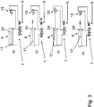
- FIG. 3 schematically, a basic principle for implementing a method for operating a creel, in which case the depressurization is achieved by a position switching valve in the sensor area 15 located outside the pneumatic cylinder 4.
- the position switching valve is switched by a mechanical contact when the end position is reached.
- the basic principle is shown in general, how it can be operated by means of a wide variety of devices and also by means of the control unit 1 according to the invention.
- a valve unit 5 of the control unit 1 is moved into an open position and compressed air flows into the pneumatic cylinder 4, which extends and lifts the creel to bring it into an operating position. Simultaneously with the pressing of the first operating element 6, pressure is also applied to the pressure circuit through the position switching valve in the sensor area 15. Even if the operator lets go of the first control element 6, it remains in the pressed position. The switching back of the control unit 1 takes place in that the position switching valve in the sensor area 15 interrupts or depressurizes the pressure circuit and the control element 6 is released and the position switching valve in the sensor area 15 is switched to ready for operation.
- the active position switching valve is triggered, and at the same time the first operating element 6 is pushed out again into the starting position, as described in section c) of Fig. 3 is shown.
- the pneumatic cylinder 4 is depressurized in that the working pressure output 3 and the sensor air input 7 of the control unit 1 are vented.
- creel can be lowered manually by the operator, as described in section d) of Fig. 3 is shown, this being done attenuated by the pneumatic cylinder 4.
Landscapes
- Engineering & Computer Science (AREA)
- Mechanical Engineering (AREA)
- General Engineering & Computer Science (AREA)
- Physics & Mathematics (AREA)
- Fluid Mechanics (AREA)
- Textile Engineering (AREA)
- Warping, Beaming, Or Leasing (AREA)
- Preliminary Treatment Of Fibers (AREA)
- Actuator (AREA)
Abstract
Description
- Die Erfindung betrifft eine Steuereinheit zur pneumatischen Ansteuerung eines Zylinders, insbesondere eines aktiven Spulengatters einer textilverarbeitenden Maschine oder einer Kabliermaschine, mit einem Drucklufteingang zum Anschluss einer Druckluftversorgung, einem Arbeitsluftausgang zum Betreiben des wenigstens einseitig wirkenden Zylinders einer zwischen dem Drucklufteingang und dem Arbeitsluftausgang angeordneten Ventileinheit, sowie einem Bedienelement zum Öffnen der Ventileinheit zum Auslösen einer Hubbewegung des Zylinders, insbesondere des Spulengatters. Weiterhin betrifft die Erfindung ein Spulengatter für eine textilverarbeitende Maschine, insbesondere für eine Kabliermaschine. Schließlich umfasst die Erfindung ein Verfahren zum aktiven pneumatischen Bewegen, insbesondere Anheben eines Spulengatters einer textilverarbeitenden Maschine, insbesondere einer Kabliermaschine.
- Spulengatter sind in vielfältiger Ausgestaltung aus dem Stand der Technik bekannt. Dabei werden die Spulengatter bei textilverarbeitenden Maschinen, wie Spinn- oder Zwirnmaschinen, insbesondere Kalbiermaschinen, regelmäßig eingesetzt, um wenigstens eine, bevorzugt mehrere Vorlagespulen bereitzuhalten. Dazu sind die Spulengatter häufig über oder hinter einer oder mehreren Arbeitsstellen einer Kabliermaschine positioniert. Um zum Vorlagespulenwechsel besser an das Spulengatter gelangen zu können, lassen sich die Spulengatter häufig mittels eines Schwenkarms in eine bedienungsgerechte Lage verschwenken. Anschließend muss das Spulengatter wieder in eine obere, schwer zugängliche Gebrauchsposition gebracht werden, um Platz zu sparen und eine bessere Zugänglichkeit des Restes der textilverarbeitenden Maschine zu erreichen. Dies erfolgt geläufig pneumatisch, insbesondere mittels eines Pneumatikzylinders, wobei auch rein mechanische und/oder händische sowie hydraulische Lösungen bekannt sind.
- Dabei werden die aus dem Stand der Technik bekannten, pneumatisch verschwenkbaren Spulengatter über einen Taster an einem Steuerventil betätigt, wobei ein Bediener den Taster über die gesamte Zeit einer Aufwärtsschwenkbewegung gedrückt halten muss bis das Spulengatter in einer stabilen Endposition angekommen ist. Üblicherweise weisen diese pneumatisch verschwenkbaren Spulengatter einen einseitig wirkenden Pneumatikzylinder auf, sodass die Abwärtsschwenkbewegung des Spulengatters händisch erfolgt. Dabei komprimiert sich die Luft im Pneumatikzylinder bzw. in dessen Kolbenraum, sodass der Bediener das Spulengatter ab einem Verschwenkwinkel des Spulengatters von etwa 20° - 30° (abhängig von der Spulenbeladung) loslassen kann und nicht weiter führen muss. Die weitere Abwärtsbewegung erfolgt dann automatisch gegen ein ablüftendes dämpfendes Druckpolster bis in eine untere Endlage.
- Aus der Druckschrift
EP 1 357 209 A2 ist bereits ein Spulengatter für Textilmaschinen bekannt, das mittels eines Gelenkvierecks an einer an dem Maschinengestell der Textilmaschine angeordneten, das feststehende Glied des Viergelenks bildenden Halterung verschwenkbar gelagert ist und mittels eines einerseits an der Halterung und andererseits an einem der beweglichen Viergelenkglieder angelenkten Pneumatikzylinders aus einer unteren Beladeposition in eine obere Betriebsposition verschwenkbar ist, wobei zum Verschwenken des Spulengatters aus der Betriebsposition in die Beladeposition der Pneumatikzylinder ein zweiseitig mit Druckluft beaufschlagbarer Pneumatikzylinder ist. - Der Erfindung liegt die Aufgabe zugrunde, eine Steuereinheit zur pneumatischen Ansteuerung eines Zylinders, ein Spulengatter für eine textilverarbeitende Maschine sowie ein Verfahren zum aktiven pneumatischen Bewegen eines Zylinders bereitzustellen, wobei das Spulengatter eine besonders einfache Ansteuerung mittels der Steuereinheit aufweist, sodass ein Bediener das Spulengatter einfacher, schneller und sicherer benutzen kann und zudem das Spulengatter vor einer Beschädigung durch eine Fehlbedienung geschützt ist.
- Die Aufgabe wird erfindungsgemäß durch eine Steuereinheit gemäß Anspruch 1, ein Spulengatter gemäß Anspruch 8 sowie ein Verfahren zum Bewegen eines Spulengatters gemäß Anspruch 13 gelöst. Vorteilhafte Weiterbildungen der Erfindung sind in den abhängigen Ansprüchen angegeben.
- Die erfindungsgemäße Steuereinheit zur pneumatischen Ansteuerung eines Zylinders, insbesondere eines aktiven Spulengatters einer textilverarbeitenden Maschine oder einer Kabliermaschine, weist einen Drucklufteingang zum Anschluss einer Druckluftversorgung an die Steuervorrichtung, einen Arbeitsluftausgang zum Betreiben des wenigstens einseitig wirkenden Zylinders, eine zwischen dem Drucklufteingang und dem Arbeitsluftausgang angeordnete bzw. wirkende Ventileinheit sowie ein Bedienelement zum Öffnen der Ventileinheit zum Auslösen einer Hubbewegung des Zylinders, insbesondere eines Spulengatters, mittels des an dem Arbeitsluftausgang angeschlossenen Zylinders auf. Dabei ist die Steuereinheit derart gebildet, dass eine selbsthaltende Ventilfunktion erreicht wird, bei der bei einer nur einmaligen und/oder kurzzeitigen Betätigung des Bedienelements die Hubbewegung des Zylinders vollständig ausgeführt wird. Weiterhin ist vorgesehen, dass die Steuereinheit derart mit einen Endlagensensor des Zylinders verbindbar ist, dass bei einer Aktivierung des Endlagensensors die Ventileinheit geschlossen wird und/oder der am Arbeitsluftausgang angeschlossene Zylinder bei oder nach dem Erreichen einer Endlage automatisch drucklos wird.
- Das erfindungsgemäße Spulengatter für eine textilverarbeitende Maschine, insbesondere für eine Kabliermaschine, weist eine erfindungsgemäße Steuereinheit sowie einen wenigstens einseitig wirkenden Zylinder zum Ausführen einer Hubbewegung des Spulengatters an der textilverarbeitenden Maschine auf, wobei die Steuereinheit und/oder der Zylinder derart gebildet sind, dass der Zylinder bei oder nach dem Erreichen einer Endlage der Hubbewegung automatisch drucklos wird.
- Das erfindungsgemäße Verfahren zum aktiven pneumatischen Bewegen, insbesondere Anheben, eines Zylinders, insbesondere eines Spulengatters einer textilverarbeitenden Maschine oder einer Kabliermaschine, umfasst als Verfahrensschritte zunächst ein Betätigen eines Bedienelements einer Steuereinheit, insbesondere einer erfindungsgemäßen Steuereinheit, wodurch eine zwischen einem Drucklufteingang und einem Arbeitsluftausgang angeordnete Ventileinheit der Steuereinheit wenigstens solange geöffnet wird, dass eine Bewegung des Zylinders, insbesondere Hubbewegung des Spulengatters, mittels eines an dem Arbeitsluftausgang angeschlossenen, wenigstens einseitig wirkenden Zylinders vollständig ausgeführt wird. Der nachfolgende Verfahrensschritt ist dann ein Überwachen der Bewegung des Zylinders mittels der Steuereinheit, wobei bei einem ansteigenden Druck und/oder einem Überschreiten eines Schwellendruckwerts an einem Sensorlufteingang der Steuereinheit die Ventileinheit geschlossen wird und/oder der am Arbeitsluftausgang angeschlossene Zylinder bei oder nach dem Erreichen einer Endlage automatisch drucklos wird.
- Die Erfinder sind im Rahmen der vorliegenden Erfindung zu einer neuen speziellen Steuereinheit mit einer neuen Ventileinheit als Steuerventil für einen neuen speziellen Zylinder gelangt. Dabei ermöglicht die Erfindung eine besonders einfache Bewegungssteuerung, die rein pneumatisch erfolgt. Weiterhin ist aufgrund eines binären Bedienprinzips - der Bediener muss das Bedienelement zum Auslösen der Hubbewegung nur kurz drücken - das Risiko von Bedienfehlern, insbesondere durch ein nicht vollständiges Ausführen der Hubbewegung, erheblich gesenkt oder sogar ausgeschlossen. Dass der Bediener das Bedienelement nicht über die gesamte Bewegungszeit während der Hubbewegung gedrückt halten muss, führt zudem zu einer schnelleren Bedienbarkeit und entsprechend kürzeren Handhabungszeit sowie zu einer erhöhten Betriebssicherheit, da der Bediener nach der Betätigung des Bedienelements einen sicheren Abstand vom verschwenkenden Spulengatter einnehmen kann. Weiterhin wird dadurch, dass der Zylinder beim Erreichen der Endlage drucklos wird, eine Druckdauerbelastung vermieden, wodurch ein kostengünstigerer Zylinder verwendet werden kann und zudem der Verschleiß reduziert und somit defekt- oder wartungsbedingte Ausfallzeiten deutlich reduziert werden können. Schließlich ermöglicht die erfindungsgemäße Steuereinheit eine deutlich kompaktere Bauweise.
- Bei der Steuereinheit kann es sich grundsätzlich um ein beliebiges Bauteil oder eine beliebige Gruppe von Bauteilen handeln, wobei die Steuereinheit immer zur pneumatischen Steuerung wenigstens eines Zylinders vorgesehen ist. Bevorzugt ist die Steuereinheit eine kompakte bzw. integrale Einheit, deren Bestandteile besonders bevorzugt vollständig an und/oder innerhalb eines Gehäuses angeordnet sind. Ganz besonders bevorzugt ist die Ventileinheit vollständig innerhalb des Gehäuses angeordnet. Das wenigstens eine Bedienelement, insbesondere alle Bedienelemente, und/oder der Drucklufteingang und/oder der Arbeitslufteingang und/oder der Sensorlufteingang sind bevorzugt unmittelbar am Gehäuse angeordnet. Grundsätzlich kann die Steuereinheit auch weitere, über die pneumatische Steuerung eines oder mehrerer Zylinder hinausgehende Funktionen aufweisen, wobei die Steuereinheit bevorzugt keine weiteren Funktionen erfüllt. Darüber hinaus kann das Bedienelement auch grundsätzlich außerhalb und/oder nicht als Teil der Steuereinheit, insbesondere als Fernbedienung, gebildet sein.
- Eine textilverarbeitende Maschine im Sinne der Erfindung kann grundsätzlich jede Maschine sein, die ein Textil bearbeitet und dabei insbesondere entweder einen Faden, ein Zwirn, einen Faserstrang oder dergleichen erzeugt oder verarbeitet. Bevorzugt werden an der Textilmaschine Fäden, Zwirne oder dergleichen zur weiteren Verarbeitung vorgelegt und dazu insbesondere an einem Spulengatter angeordnet. Besonders bevorzugt ist die textilverarbeitende Maschine eine Spinn- oder Zwirnmaschine und ganz besonders bevorzugt eine Kabliermaschine.
- Ein Spulengatter ist eine Vorrichtung und insbesondere ein Teil einer Textilmaschine, mittels der wenigstens eine Spule, insbesondere eine Vorlagespule, gelagert und vorzugsweise auch der Textilmaschine zugeführt werden kann. Dazu kann das Spulengatter bevorzugt eine Verschwenkbewegung zwischen einer bedienungsgerechten Lage zum Bestücken des Spulengatters mit Spulen und einer Gebrauchslage ausführen, wobei besonders bevorzugt die Gebrauchslage räumlich oberhalb der bedienungsgerechten Lage gelegen ist. Vorzugsweise erfolgt wenigstens die Hubbewegung in die Gebrauchslage mittels eines Arbeitsfluids und dabei bevorzugt pneumatisch oder alternativ auch hydraulisch, insbesondere mittels wenigstens eines Zylinders. Ein Spulengatter, das in wenigstens einer Richtung pneumatisch oder motorisch verschwenkbar ist, wird dabei als aktives Spulengatter bezeichnet. Besonders bevorzugt erfolgt das Verschwenken und ganz besonders bevorzugt der gesamte Betrieb des Spulengatters ausschließlich pneumatisch und gegebenenfalls ergänzend händisch bzw. manuell durch einen Bediener. Ebenfalls bevorzugt ist das Spulengatter als eine einzige integrale Einheit mit einer speziellen Zylinderausführung gebildet. Das vollständige Ausführen einer Hubbewegung des Spulengatters wird als der Vorgang verstanden, bei dem die Ventileinheit dauerhaft bzw. solange offengehalten wird, bis eine Endlage des Spulengatters und/oder des Zylinders erreicht ist, wobei nach dem vollständigen Ausführen der Hubbewegung besonders bevorzugt ein pneumatischer Kolben des Zylinders vollständig ausgefahren ist.
- Der Drucklufteingang ist erfindungsgemäß an der Steuereinheit vorgesehen, um die Steuereinheit an eine Arbeitsfluidversorgung, insbesondere eine Druckluftversorgung, anzuschließen. Durch das Zuführen von Druckluft zur Steuereinheit wird ein pneumatischer Antrieb wenigstens eines Zylinders des Spulengatters zum Durchführen einer Hubbewegung ermöglicht. Bevorzugt strömt die gesamte zum Betrieb des Zylinders, insbesondere aller Zylinder, des Spulengatters benötigte Druckluft vollständig durch die Steuereinheit. Um einen besonders einfachen Anschluss der Druckluftversorgung zu ermöglichen, handelt es sich bei dem Drucklufteingang und/oder dem Arbeitslufteingang und/oder dem Sensorlufteingang bevorzugt um einen standardisierten Anschluss, wobei ganz besonders bevorzugt alle Eingänge und Ausgänge der Steuereinheit identisch zueinander gebildet sind. Bei der dem Drucklufteingang zuzuführenden Druckluft handelt es sich bevorzugt um komprimierte Luft, die besonders bevorzugt einen Druck von etwa 6 bar aufweist. Grundsätzlich kann jedoch jedes Gas oder Gasgemisch mit einem beliebigen, zum Betrieb des Zylinders ausreichend hohen Druck in der Steuereinheit verwendet werden.
- Der Arbeitsluftausgang ist erfindungsgemäß dafür vorgesehen, ein Arbeitsfluid, insbesondere Druckluft, von der Steuereinheit zum Zylinder leiten zu können. Bevorzugt ist dazu der Arbeitsluftausgang über die Ventileinheit unmittelbar mit dem Drucklufteingang verbindbar. Der Arbeitsluftausgang ist bevorzugt zum Anschluss einer Druckluftleitung gebildet. Weiterhin bevorzugt beträgt der maximale Druck am Arbeitslufteingang dem Druck der durch den Drucklufteingang zugeführten Druckluft.
- Die Ventileinheit ist grundsätzlich ein Bauteil oder eine Baugruppe der Steuereinheit, die wenigstens eine Verbindung zwischen dem Drucklufteingang und dem Arbeitsdruckausgang herstellen und trennen kann bzw. einen Durchgang zwischen dem Drucklufteingang und dem Arbeitsdruckausgang öffnet und schließt. Eine Druckregelung durch die Ventileinheit muss dabei nicht gegeben sein. Bei einer vorteilhaften Weiterbildung der Ventileinheit ist es jedoch denkbar, eine Einstellbarkeit der Ventileinheit mit mehreren Druckstufen vorzusehen oder die Ventileinheit sogar stufenlos regelbar zu machen. Bevorzugt ist die Steuereinheit derart gebildet, dass sich die Ventileinheit in einer Ausgangsstellung der Steuereinheit in der geschlossenen Position befindet, wobei die Steuereinheit, besonders bevorzugt das Bedienelement und/oder ein Schieber der Steuereinheit pneumatisch oder mechanisch, insbesondere mittels einer Feder, auf die geschlossene Position der Ventileinheit hin vorgespannt ist.
- Bei dem wenigstens einseitig wirkenden Zylinder kann es sich um einen beliebigen, pneumatisch oder hydraulisch betreibbaren Zylinder oder alternativ um einen anderen, linear wirkenden, insbesondere in wenigstens eine Raumrichtung verlängerbaren Aktor handeln. Bevorzugt ist der Zylinder ausschließlich in der ausfahrenden Richtung aktiv angetrieben bzw. mit Druckluft beaufschlagbar. Dabei ist der Zylinder bevorzugt ein Hubzylinder und weist besonders bevorzugt einen in eine Richtung durch Druckluft verschieblichen Kolben mit einer daran angeordneten Kolbenstange auf, wobei die Kolbenstange in Bezug zum Zylindergehäuse Arbeit verrichten kann. Bei einem einseitig wirkenden Zylinder befindet sich bevorzugt auf einer Seite des Kolbens eine Druckkammer, die besonders bevorzugt in jeder Position des Kolbens im Wesentlichen geschlossen ist, gegebenenfalls bis auf die Ausnahme einer oder mehrerer Drosselöffnungen. Weiterhin bevorzugt befindet sich auf der der Druckkammer gegenüberliegenden Seite des Zylinders und insbesondere im Bereich des Austritts der verschieblichen Kolbenstange aus dem Zylinder wenigstens eine Entlüftungsbohrung, sodass beim Verschieben des Kolbens aufgrund der in die Druckkammer einströmenden Druckluft auf der gegenüberliegenden Seite des Kolbens keine Kompression der Luft erfolgt. Besonders bevorzugt sind wenigstens zwei Entlüftungsbohrungen sich in Bezug zur Kolbenstange bzw. der Mittellängsachse des Zylinders gegenüberliegend an einem Zylinderende angeordnet.
- Das Bedienelement kann zunächst ein beliebiges Bauteil oder eine beliebige Funktionseinheit sein, die wenigstens zwei Positionen oder Zustände aufweist. Das Bedienelement ist bevorzugt ein Taster und besonders bevorzugt ein Druckknopf. Weiterhin bevorzugt ist das Bedienelement durch Drücken betätigbar. Darüber hinaus kann die Steuereinheit auch ein zweites oder sogar weitere Bedienelemente aufweisen, wobei bevorzugt wenigstens ein erstes und ein zweites Bedienelement und besonders bevorzugt sämtliche Bedienelemente zueinander identisch gebildet sind.
- Unter einer selbsthaltenden Ventilfunktion wird verstanden, dass die Ventileinheit wenigstens eine Position aufweist, in der es nach einem Überführen in dieser Position verbleibt, bis es aufgrund einer äußeren bzw. von außen gesteuerten Krafteinwirkung wieder aus dieser Position herausbewegt wird. Besonders bevorzugt ist dies die geöffnete Position der Ventileinheit. Weiterhin bevorzugt umfasst die selbsthaltende Ventilfunktion, dass die Ventileinheit durch eine kurze Betätigung des Bedienelements von der geschlossenen in die geöffnete Position gebracht werden kann und dann dort - auch ohne weitere Betätigung des Bedienelements - verbleibt bis die Ventileinheit durch eine weitere, gezielte Krafteinwirkung wieder in die geschlossene Position bewegt wird. Somit ist die Steuereinheit derart gebildet, dass eine selbsthaltende Ventilfunktion erreicht wird, bei der bei einer nur einmaligen und/oder kurzzeitigen Betätigung des Bedienelements die Ventileinheit in der geöffneten Position bleibt, sodass die Hubbewegung des Spulengatters vollständig ausgeführt wird.
- Bei einem ansteigenden Druck und/oder dem Überschreiten eines Schwellendruckwerts am Sensorlufteingang, insbesondere beim Erreichen einer Endlage eines angeschlossenen Zylinders und präziser beim Erreichen einer Endlage des Kolbens eines angeschlossenen Zylinders, wird die Ventileinheit geschlossen, wobei besonders bevorzugt der am Sensorlufteingang der Steuereinheit anliegende Gasdruck die Ventileinheit unmittelbar von der geöffneten in die geschlossene Position überführt. Dabei wird der Schwellendruckwert am Sensorlufteingang bevorzugt in Bezug zum Druck am Arbeitsluftausgang festgelegt, wobei der Schwellendruckwert bevorzugt mehr als 50 %, besonders bevorzugt zwischen 50 % und 200 %, ganz besonders bevorzugt zwischen 75 % und 150 % und insbesondere bevorzugt zwischen 80 % und 120 % des Drucks am Arbeitsluftausgang beträgt. Insbesondere im Zusammenhang mit einer den Kolben des Zylinders durchdringenden Drosselöffnung ist eine solche Grenzwertfestlegung sinnvoll. Grundsätzlich kann der Schwellendruckwert jedoch beliebig an die jeweiligen Erfordernisse und insbesondere den mechanischen Aufbau des Spulengatters angepasst werden.
- Erfindungsgemäß wird der am Arbeitsluftdruckausgang angeschlossene Zylinder beim Erreichen einer Endlage automatisch drucklos, wobei das automatische Druckloswerden des Zylinders mittels wenigstens einer Entlüftungsbohrung im Zylinder und/oder mittels eines Positionsschaltventils oder in beliebiger anderer Weise erreicht werden kann, wobei bevorzugt das Positionsschaltventil oder die Ventileinheit der Steuereinheit den Zylinder aktiv entlüftet. Dabei kann ein Positionsschaltventil beispielsweise mittels eines mechanischen Kontakts zur Detektion der Endlage geschaltet werden. Das Positionsschaltventil und/oder der mechanische Kontakt, insbesondere ein Lagekontakt, kann dabei gestellfest und/oder am Spulengatter und/oder am bzw. im Zylinder angeordnet sein. Darüber hinaus ist auch ein pneumatischer Sensorbereich innerhalb des Zylinders denkbar, um die Endlage zu erfassen.
- Unter einer Betätigung des Bedienelements wird jede Bedienung verstanden, bei der das Bedienelement von einem definierten Zustand durch einen Bediener in einen anderen definierten Zustand gebracht wird. Dabei kann die Betätigung sowohl dauerhaft, als auch nur einmalig und/oder kurzzeitig erfolgen, wobei bevorzugt beide Arten der Betätigung zum gleichen Zustand der Steuereinheit führen.
- Unter dem Überwachen der Hubbewegung des Zylinders mittels der Steuereinheit wird zunächst lediglich verstanden, dass ein spezifischer Zustand des Zylinders, insbesondere das Erreichen der Endlage, ermittelt wird. Eine durchgehende Überwachung der Position des Kolbens im Zylinder ist dafür nicht notwendig, kann aber zusätzlich auch vorgenommen werden. Zudem kann die Überwachung der Hubbewegung auch eine zeitweise oder durchgehende Überwachung des Drucks am Arbeitsluftausgang und/oder am Sensorlufteingang umfassen, um beispielsweise Überlastungszustände des Zylinders zu detektieren.
- Besonders bevorzugt ist eine Ausführung der erfindungsgemäßen Steuereinheit, die einen Sensorlufteingang zum Verbinden eines Endlagensensors aufweist, wobei bei einem Druckanstieg und/oder einem Überschreiten eines Schwellendruckwerts und/oder der Wegfall eines Sensordrucks am Sensorlufteingang die Ventileinheit geschlossen wird und/oder der am Arbeitsluftausgang angeschlossene Zylinder bei oder nach dem Erreichen einer Endlage automatisch drucklos wird, wodurch die Steuereinheit sowie der damit verbundene Endlagensensor rein pneumatisch betrieben werden können. Der Endlagensensor kann dabei grundsätzlich ein beliebig mechanisch, elektronisch, pneumatisch und/oder hydraulisch wirkender bzw. betriebener Sensor sein. Bevorzugt leitet der Sensor Signale pneumatisch weiter und besonders bevorzugt ist der Sensor vollständig pneumatisch betrieben.
- Gemäß einer vorteilhaften Weiterbildung der erfindungsgemäßen Steuereinheit ist diese derart gebildet, dass das Bedienelement nach der nur einmaligen und/oder kurzzeitigen Betätigung, insbesondere automatisch, deaktiviert wird und bevorzugt bei einem Druckanstieg am Sensorlufteingang und/oder einem Überschreiten eines Schwellendruckwerts und/oder der Wegfall eines Sensordrucks am Sensorlufteingang wieder aktiviert wird, wodurch in einfacher Weise eine Fehlbedienung des Bedienelements ausgeschlossen wird. Unter einem Deaktivieren wird zunächst lediglich verstanden, dass das Bedienelement in einen Betriebszustand gelangt oder gebracht wird, in dem eine erneute Betätigung nicht möglich ist und/oder zu keinem weiteren Effekt, insbesondere zu keiner Änderung des Zylinders und/oder der Hubbewegung des Spulengatters, führt. Entsprechend wird unter einer Aktivierung verstanden, dass das Bedienelement in einen Betriebszustand gelangt oder gebracht wird, in dem eine erneute Betätigung möglich ist und/oder zu einem Effekt, insbesondere dem Öffnen der Ventileinheit, führt.
- Nach einer bevorzugten Ausgestaltung der erfindungsgemäßen Steuereinheit weist die Ventileinheit einen Schieber auf, der durch die Betätigung des Bedienelements im Inneren der Steuereinheit zwischen einer geöffneten und geschlossenen Position, insbesondere von einer geschlossenen in eine geöffnete Position der Ventileinheit verschiebbar ist, wobei der Schieber besonders bevorzugt einen Kanal bzw. eine Freimachung aufweist, der nur in der geöffneten Position den Drucklufteingang mit dem Arbeitsluftausgang verbindet, wodurch eine sichere und zuverlässige Funktion der Ventileinheit in einfacher Weise sichergestellt wird und eine Fehlbedienung im Sinne eines Einstellens unerwünschter Ventilzustände ausgeschlossen ist. Dabei kann der Kanal grundsätzlich in beliebiger Weise gestaltet sein, solange der Kanal in der geöffneten Position der Ventileinheit den Drucklufteingang mit dem Arbeitsluftausgang verbindet. Bevorzugt verbindet der Kanal den Drucklufteingang ausschließlich mit dem Arbeitsluftausgang bzw. verläuft lediglich zwischen dem Drucklufteingang und dem Arbeitsluftausgang. Dabei kann der Kanal auch zumindest abschnittsweise im Inneren des Schiebers verlaufen oder ausschließlich an der Oberfläche des Schiebers, insbesondere als gerade Nut oder Ausnehmung, gebildet sein. Weiterhin bevorzugt weist der Kanal eine zur Position des Drucklufteingangs und/oder des Arbeitsluftausgangs am Gehäuse der Steuereinheit jeweils korrespondierende Öffnung bzw. eine korrespondierende Ausdehnung auf, um in der geöffneten Position der Ventileinheit den Drucklufteingang mit dem Arbeitsluftausgang zu verbinden.
- Der Schieber ist bevorzugt vollständig innerhalb eines Gehäuses der Steuereinheit angeordnet.
- Ebenfalls bevorzugt ist der Schieber zylinderförmig und/oder entlang der Mantelfläche bzw. entlang seiner Verschieberichtung an dem Gehäuse der Steuereinheit geführt und dabei besonders bevorzugt verdrehgesichert. Weiterhin bevorzugt ist der Schieber durch das Bedienelement linear verschiebbar. Dazu ist das Bedienelement bzw. ein verschieblicher Teil des Bedienelements besonders bevorzugt unmittelbar an dem Schieber angeordnet. Die Betätigungsrichtung des Bedienelements entspricht weiterhin bevorzugt der Richtung der Verschiebbarkeit des Schiebers und besonders bevorzugt sind das Bedienelement und der Schieber koaxial, ganz besonders bevorzugt entlang einer gemeinsamen Achse verschieblich angeordnet.
- Insbesondere vorteilhaft ist eine Ausgestaltung der erfindungsgemäßen Steuereinheit bei der ein Magnet am Schieber und/oder dem Schieber gegenüberliegend am Gehäuse der Steuereinheit derart angeordnet ist, dass der Schieber in der geöffneten Position der Ventileinheit durch die Kraft des Magneten in der geöffneten Position gehalten wird, wodurch in einfacher Weise eine Steuereinheit mit einer speziellen magnetischen Haltefunktion der Ventileinheit gebildet wird, die zu einer selbsthaltenden Ventilfunktion führt, sodass auch bei nur kurzzeitiger Betätigung des Bedienelements die Ventileinheit weiterhin zuverlässig in der geöffneten Position verbleibt. Bevorzugt ist der Magnet in der geöffneten Position der Ventileinheit bzw. der entsprechenden Position des Schiebers nahe genug an der gegenüberliegenden, magnetisch wechselwirkenden Oberfläche des Schiebers bzw. des Gehäuses angeordnet, dass eine ausreichend starke magnetische Wechselwirkung stattfindet, während in der geschlossenen Position der Ventileinheit bzw. der entsprechenden Position des Schiebers die magnetische Wechselwirkung wenigstens so schwach ist, dass der Schieber nicht in die geöffnete Position gezogen wird. Weiterhin bevorzugt ist der Magnet ein Permanentmagnet, wobei auch eine Gestaltung als Elektromagnet denkbar ist. Schließlich ist bevorzugt, dass dem Magnet gegenüberliegend in der Steuereinheit, besonders bevorzugt am Gehäuse der Steuereinheit, eine Metallplatte aus einem magnetisch anziehbaren Material, insbesondere aus Eisen, angeordnet ist. Alternativ zu dem Magneten kann auch ein anderes, den Schieber in seiner Position haltendes Element, beispielsweise ein Saugnapf oder eine Klettverbindung, vorgesehen sein.
- Gemäß einer vorteilhaften Weiterbildung der erfindungsgemäßen Steuereinheit ist der Sensorlufteingang derart angeordnet, dass ein daran angelegter Druck der Kraft des Magneten entgegenwirkt, wobei dazu bevorzugt der Sensorlufteingang mit einem Ventilraum verbunden ist, der zwischen dem Gehäuse der Steuereinheit, insbesondere einer daran angeordneten Metallplatte, und dem Magneten angeordnet ist, wodurch in einfacher Weise die Ventileinheit unmittelbar durch einen ansteigenden Druck am Sensorlufteingang von der geöffneten Position in die geschlossene Position verstellt werden kann. Ein ansteigender Druck am Sensorlufteingang führt dabei in einfacher Weise zu einer sprunghaften Positionsänderung von der geöffneten Position in die geschlossene Position der Ventileinheit sobald der Druck die Haltekraft des Magneten überschreitet. Dabei ist der Ventilraum bevorzugt derart angeordnet, dass ein Druckanstieg zu einer direkten Verschiebung des Schiebers in die geschlossene Position führt und/oder das durch den Sensorlufteingang eingeleitete Gas unmittelbar auf den Schieber wirkt.
- Bei einer bevorzugten Ausgestaltung der erfindungsgemäßen Steuereinheit ist eine Feder, insbesondere eine Spiralfeder, derart angeordnet, dass das Bedienelement auf die Stellung einer geschlossenen Position der Ventileinheit vorgespannt ist. Weiterhin bevorzugt wirkt die Federkraft der Kraft des Magneten und insbesondere der magnetischen Wirkrichtung entgegen, sodass nach einem Überwinden der magnetischen Kraft mittels eines am Sensorlufteingang angelegten Drucks die Ventileinheit, insbesondere der Schieber, und/oder das Bedienelement vollständig und zuverlässig in die Ausgangsposition bzw. die geschlossene Position bewegt werden. Diese Bewegung entspricht dabei einer automatischen Reaktivierung bzw. einer Rückstellung in die Ausgangslage des Bedienelements.
- Eine bevorzugte Weiterbildung der erfindungsgemäßen Steuereinheit ist durch ein zweites Bedienelement gekennzeichnet, das nur aktiviert bzw. bedienbar ist, wenn das erste Bedienelement betätigt wurde und/oder mittels dem die Position und/oder die Funktion des ersten Bedienelements umgehend umkehrbar ist, wodurch in einfacher und für den Bediener in intuitiver Weise eine weitere Bedienfunktion und insbesondere ein Abbruch der durch das erste Bedienelement ausgelösten Funktion möglich ist. Mittels des zweiten Bedienelements kann insbesondere in einfacher Weise ein betätigtes erstes Bedienelement, dessen Betätigung die Ventileinheit geöffnet und entsprechend eine Hubbewegung des Spulengatters ausgelöst hat, wieder in die Ausgangsstellung gebracht werden, wodurch die Ventileinheit unabhängig von der Position des Spulengatters entlang der Hubbewegung und insbesondere vor Erreichen der Endlage umgehend in eine geschlossene Position gebracht werden kann. Zudem ist eine Rückstellung des ersten Bedienelements in die Ausgangslage auch unabhängig von dem Druck am Sensorlufteingang möglich. Entsprechend unterbricht das zweite Bedienelement den nach einer Betätigung des ersten Bedienelements ablaufenden Verfahrenszyklus umgehend, sodass das Selbsthalten der Ventilfunktion beendet werden kann. Das erste und zweite Bedienelement sind miteinander bevorzugt über einen Hebel und besonders bevorzugt über eine Wippe verbunden, sodass eine Betätigung des einen Bedienelements von einer ersten in eine zweite Position automatisch zur Bewegung des anderen Bedienelements von der zweiten in die erste Position bewirkt. Entsprechend befinden sich die beiden Bedienelemente grundsätzlich in sich unterscheidenden Zuständen. Insbesondere ist das eine Bedienelement stets eingedrückt und/oder deaktiviert, wenn sich das andere Bedienelement in einer drückbaren, ausgezogenen Position befindet und/oder entsprechend aktiviert ist.
- Alternativ ist auch eine Ausführung denkbar, bei der nur ein Bedienelement vorgesehen ist, das derart gestaltet ist, dass es nach einer Betätigung manuell rückgestellt, insbesondere aus einer gedrückten Position wieder herausgezogen werden kann. Dabei ist das Bedienelement besonders bevorzugt als Pilzkopf-Schalter bzw. -Knopf gebildet. Weiterhin bevorzugt erfolgt ein umgehender Abbruch des ablaufenden Verfahrenszyklus bei einem Herausziehen bzw. manuellen Rückstellen des ersten Bedienelements.
- Bei einer bevorzugten Ausgestaltung des erfindungsgemäßen Spulengatters weist der Zylinder an einem Ende, insbesondere im Bereich einer Kolbenstangenaustrittsöffnung, einen Sensorbereich mit einem Sensorluftausgang, insbesondere als Endlagensensor, auf, der zum Schließen der Ventileinheit mit dem Sensorlufteingang der Steuereinheit verbunden ist. Dabei ist der Sensorbereich bevorzugt derart gebildet, dass kurz vor dem Erreichen der Endlage des Kolbens im Zylinder ein Druckanstieg im Sensorbereich erfolgt, wodurch in besonders einfacher Weise pneumatisch die Endlage ermittelt werden kann. Dabei wirkt der Sensorbereich als Endanschlagssensor, insbesondere als pneumatischer Endanschlagssensor. Insbesondere vorteilhaft kann dabei zugleich ein Gas komprimiert werden, das am Sensorlufteingang der Steuereinheit angelegt werden kann und dann dort besonders bevorzugt unmittelbar die Ventileinheit in die geschossene Position bringt. Dabei ist der Sensorluftausgang des Zylinders bevorzugt unmittelbar mit dem Sensorlufteingang der Steuereinheit verbindbar bzw. kann zum bestimmungsgemäßen Gebrauch der Steuereinheit unmittelbar damit verbunden werden.
- Gemäß einer vorteilhaften Weiterbildung des erfindungsgemäßen Spulengatters weist der Zylinder im Inneren an einem Ende, insbesondere im Sensorbereich, einen querschnittsreduzierten Bereich auf. Weiterhin ist an dem Kolben an dem auf den querschnittsreduzierten Bereich zuweisenden Seite ein Sensorkolben mit einem dem Durchmesser des querschnittsreduzierten Bereichs entsprechenden Durchmesser angeordnet, der kurz vor dem Erreichen der Endlage des Kolbens im Zylinder in den querschnittsreduzierten Bereich eintritt, sodass der Druck im Sensorbereich und somit am Sensorluftausgang ansteigt. Durch einen solchen ansteigenden Druck ist die Detektion der Endlage mittels einer besonders einfachen Konstruktion und besonders ausfallsicher möglich. Bevorzugt weisen das Innere des Zylinders und/oder der querschnittsreduzierte Bereich eine zylindrische Form und/oder einen gleichbleibenden Durchmesser über die gesamte Länge auf. Weiterhin bevorzugt hat der Kolben einen an das Innere des Zylinders angepassten Durchmesser und weist eine an den Zylinderinnenraum angepasste, insbesondere zylindrische Form auf. Ebenfalls bevorzugt ist die wenigstens eine Entlüftungsbohrung und besonders bevorzugt sind sämtliche Entlüftungsbohrungen außerhalb des querschnittsreduzierten Bereichs und ganz besonders bevorzugt dabei in einem an den querschnittsreduzierten Bereich angrenzenden Bereich angeordnet.
- Das Innere des querschnittsreduzierten Bereichs bildet vorzugsweise einen verkleinerten Kolbenraum, innerhalb den der Sensorkolben, nicht jedoch der Kolben mit dem größeren Durchmesser, der dem Inneren des Zylinders entspricht, einschiebbar ist. Weiterhin bevorzugt ist der querschnittsreduzierte Bereich an dem Ende des Zylinders, an dem die Kolbenstange aus dem Zylinder austritt, angeordnet, und dabei besonders bevorzugt im bzw. als Teil des Kolbendeckels gebildet. Der Durchmesser des querschnittsreduzierten Bereichs ist bevorzugt wenigstens 5 %, besonders bevorzugt zwischen 10 % und 50 % und ganz besonders bevorzugt zwischen 15 % und 30 % kleiner als der Durchmesser des übrigen Inneren des Zylinders, insbesondere dem Bereich innerhalb dem der Kolben verschiebbar ist. Schließlich weist der Sensorkolben eine Länge entlang der Mittellängsachse der Kolbenstange auf, die bevorzugt zwischen 10 % und 100 %, besonders bevorzugt zwischen 20 % und 80 % und ganz besonders bevorzugt wenigstens 50 % der Länge des Sensorbereichs bzw. des querschnittsreduzierten Bereichs in dieser Richtung entspricht.
- Bei einer möglichen Weiterbildung des erfindungsgemäßen Spulengatters ist im Kolben wenigstens eine den Kolben durchdringende Drosselöffnung vorgesehen, um den Druckaufbau im Sensorbereich beim Erreichen der Endlage mittels der Arbeitsluft zu verstärken, wodurch unabhängig von der Stellgeschwindigkeit des Kolbens im Zylinder zuverlässig die Endlage erfassbar ist. Dabei verbindet die Drosselöffnung bevorzugt die Druckkammer, an die die Arbeitsluft eingeleitet wird, unmittelbar mit der dem Kolben gegenüberliegenden Seite im Inneren des Zylinders. Weiterhin ist der Durchmesser der Drosselöffnung bevorzugt so klein gewählt, dass ein ausreichender Arbeitsdruck in der Druckkammer mittels der Arbeitsluft aus dem Arbeitsluftausgang der Steuereinheit aufgebaut werden kann, um den Zylinder mit einer ausreichenden Kraft der Kolbenstange betätigen zu können. Weiterhin bevorzugt ist der Durchmesser jedoch so groß, dass ausreichend schnell Arbeitsluft beim Erreichen der Endlage in den Sensorbereich einströmen kann, um ein schnelles und zuverlässiges Umschalten der Steuereinheit zu erreichen.
- Nach einer bevorzugten Ausgestaltung des erfindungsgemäßen Spulengatter ist dieses in einer mittels der Hubbewegung des Zylinders erreichbaren obersten Position festlegbar und wird dazu insbesondere über einen Totpunkt hinausbewegt oder mittels einer Arretiervorrichtung insbesondere wieder lösbar festgelegt, sodass der Zylinder, insbesondere die Druckkammer des Zylinders, in der Endlage und gemeinsam mit dem Schließen der Ventileinheit drucklos verbleiben kann, ohne dass sich die Position des Spulengatters verändert. Dabei kann ein Federelement derart am Spulengatter angeordnet sein, dass des Spulengatter aufgrund der Federkraft in seiner Position gehalten wird.
- Eine bevorzugte Ausgestaltung des erfindungsgemäßen Verfahrens zum aktiven pneumatischen Bewegen eines Spulengatters sieht vor, dass das Bedienelement bei dem oder nach dem Schließen der Ventileinheit wieder automatisch, insbesondere aufgrund des ansteigenden Drucks an dem Sensorlufteingang, in eine Ausgangslage gebracht und somit für eine nächste Betätigung freigegeben wird, wodurch eine besonders einfache Bedienbarkeit erreicht und eine Fehlbedienung verhindert wird.
- Gemäß einer vorteilhaften Weiterbildung des erfindungsgemäßen Verfahrens zum aktiven pneumatischen Bewegen eines Spulengatters werden beim Schließen der Ventileinheit und insbesondere einem damit einhergehenden Verschieben eines Schiebers der Ventileinheit der Sensorlufteingang und/oder der Arbeitsluftausgang der Ventileinheit zur Entlüftung freigegeben. Dadurch wird in besonders einfacher Weise der Zylinder und insbesondere eine mit dem Arbeitsluftausgang verbundenen Druckkammer auf der einen Seite des Kolbens und/oder der andere, mit dem Sensorlufteingang der Steuereinheit verbundene Teil des Zylinders auf der anderen Seite des Kolbens entlüftet und somit druckfrei gestellt. Alternativ kann ein separates und/oder zwischen Zylinder und Ventileinheit bzw. Steuereinheit zwischengeschaltetes Entlüftungsventil vorgesehen sein, um ein Entlüften zu ermöglichen.
- Ein Ausführungsbeispiel einer Steuereinheit, weiterer Teile eines Spulengatters sowie eines Verfahrens zum aktiven pneumatischen Anheben eines Spulengatters werden nachfolgend mit Bezug auf die Zeichnungen näher erläutert. In den Figuren zeigen:
- Fig. 1a
- eine perspektivische Ansicht einer Steuereinheit,
- Fig. 1b
- eine perspektivische Schnittansicht der in
Fig. 1a dargestellten Steuereinheit, - Fig. 2
- eine perspektivische Schnittansicht eines Zylinders, und
- Fig. 3
- ein Schema zur Veranschaulichung des Grundprinzips eines Verfahrens zum aktiven pneumatischen Anheben eines Spulengatters mittels einer Steuereinheit.
- Bei einer in den
Figuren 1a und1b dargestellten Ausführung einer als integralen Einheit gebildeten Steuereinheit 1 zur pneumatischen Ansteuerung eines aktiven Spulengatters einer textilverarbeitenden Kabliermaschine sind an der Außenseite eines Gehäuses 11 an einer Seite zwei Bedienknöpfe 6, 13 und an einer anderen Seite drei Anschlüsse angeordnet. Der erste Anschluss ist dabei ein Drucklufteingang 2 an den ein Druckluftschlauch zum Zuführen von Druckluft mit 6 bar Druck zur Steuereinheit 1 und nachfolgend zu einem Pneumatikzylinder 4 des Spulengatters angeordnet werden kann. Unmittelbar daneben ist als zweiter Anschluss ein Arbeitsluftausgang 3 angeordnet, der dazu vorgesehen ist, Druckluft als Arbeitsmedium zu wenigstens einem Pneumatikzylinder 4 zu leiten. Neben diesen beiden Anschlüssen ist als dritter Anschluss schließlich am Gehäuse 11 ein Sensorlufteingang 7 an der Steuereinheit 1 angeordnet, an dem eine von einem pneumatischen Sensor bzw. einem Sensorbereich 15 des Pneumatikzylinders 4 kommende Druckluftleitung angeschlossen werden kann. - Im Inneren des Gehäuses 11 der Steuereinheit 1 ist eine Ventileinheit 5 angeordnet, die im Wesentlichen aus einem innerhalb eines zylinderförmigen Abschnitts des Gehäuses 11 verschieblichen, ebenfalls zylindrischen Schieber 8 gebildet ist. Dabei ist der Schieber 8 mittels der Bedienknöpfe 6, 13 verschieblich und kann zwischen einer geschlossenen und einer geöffneten Position der Ventileinheit 5 verschoben werden. In der
Fig. 1 ist die Steuereinheit 1 mit der Ventileinheit 5 in der geöffneten Position dargestellt. - Dabei weist der Schieber 8 an seiner Oberfläche einen Kanal 9 auf, der in der geöffneten Position der Ventileinheit 5 den Drucklufteingang 2 mit dem Arbeitsluftausgang 3 verbindet. Wird der Schieber 8 in die geschlossene Position der Ventileinheit 5 verschoben, befindet sich der Kanal 9 nur noch im Bereich des Drucklufteingangs 2, jedoch nicht mehr im Bereich des Arbeitsluftausgangs 3, sodass keine Druckluft mehr aus dem Drucklufteingang 2 durch die Ventileinheit 5 in den Arbeitsluftausgang 3 und von dort weiter zu einem Pneumatikzylinder 4 strömen kann.
- Der erste Bedienknopf 6 ist unmittelbar mit dem Schieber 8 der Ventileinheit 5 verbunden, sodass ein Eindrücken des Bedienknopfes 6 den Schieber 8 in die geöffnete Position der Ventileinheit 5 verschiebt. Entsprechend löst der erste Bedienknopf 6 eine Hubbewegung des Spulengatters aufgrund einer Aktivierung des Pneumatikzylinders 4 aus. Dabei ist der Bedienknopf 6 entlang einer Mittellängsachse des Schiebers 8 bewegbar angeordnet.
- Über einen festen Wippenhebel 22 ist der erste Bedienknopf 6 mit dem zweiten, darüber angeordneten Bedienknopf 13 derart verbunden, dass sich beide Bedienknöpfe 6, 13 grundsätzlich in unterschiedlichen Betriebszuständen befinden. Wenn der erste Bedienknopf 6 gedrückt wird, kehrt der zweite Bedienknopf 13 zugleich aus der gedrückten Position heraus in eine Position, in der dieser betätigt werden kann, während eine erneute Betätigung des bereits eingedrückten ersten Bedienknopfes 6 dann nicht mehr möglich ist. Der zweite Bedienknopf 13 dient also dazu, die Funktion des ersten Bedienknopfes 6 umzukehren und einen durch den ersten Bedienknopf 6 ausgelösten Vorgang umgehend abzubrechen.
- Um eine zuverlässige, selbsthaltende Ventilfunktion zu gewährleisten, ist an einem dem ersten Bedienknopf 6 gegenüberliegenden Ende des Schiebers 8 ein Permanentmagnet 10 angeordnet, der in der geöffneten Position der Ventileinheit 5 nahe genug an eine am Gehäuse 11 der Steuereinheit 1 angeordnete Eisenplatte 26 gelangt, sodass es zur magnetischen Anziehung und somit zu einer speziellen magnetischen Haltefunktion in der geöffneten Position der Ventileinheit 5 kommt. Somit ist es zum nachfolgenden Schließen der Ventileinheit 5 notwendig, die Haltekraft des Magneten 10 zu überwinden. Die Eisenplatte 26 ist dabei bevorzugt direkt am Gehäuse 11 der Steuereinheit 1 festgelegt oder bildet ein Teil des Gehäuses 11.
- Um entgegen der Haltekraft des Magneten 10 den Schieber 8 in die geschlossene Position der Ventileinheit 5 zu verschieben, ist zwischen dem Gehäuse 11 im Bereich der Eisenplatte 26 und der den Magneten 10 aufweisenden Oberfläche des Schiebers 8 ein Ventilraum 12 angeordnet, der mit dem Sensorlufteingang 7 verbunden ist. Bei einem steigenden Druck am Sensorlufteingang 7 und somit in dem Ventilraum 12 übersteigt der auf den Schieber 8 wirkende Druck nach einer gewissen Zeit die magnetische Haltekraft abzüglich der Federkraft der Feder 23 und die Ventileinheit 5 schaltet schlagartig von der geöffneten in die geschlossene Position um.
- Um ein vollständiges und sicheres Umschalten von der geöffneten Position in die geschlossene Position zu unterstützen, ist an dem ersten Bedienknopf 6 eine Spiralfeder 23 angeordnet, die den Bedienknopf 6 entgegen der Haltekraft des Magneten 10 auf die geschlossene Position hin vorspannt. Dazu ist die Spiralfeder 23 den ersten Bedienknopf 6 umgebend angeordnet.
- Der in
Fig. 2 dargestellte Pneumatikzylinder 4 weist einen verschieblichen Kolben 17 mit einer einseitig aus dem Pneumatikzylinder 4 aus einer Kolbenstangenaustrittsöffnung 14 austretenden Kolbenstange 24 auf. Der Pneumatikzylinder 4 ist einseitig wirkend gebildet, d.h., lediglich auf der der Kolbenstange 24 gegenüberliegenden Seite des Kolbens 17 kann die aus dem Arbeitsluftausgang 3 der Steuereinheit 1 austretende Druckluft in einen Arbeitslufteingang 27 eingeleitet werden. Diese eingeleitete Druckluft verschiebt dann den Kolben 17 innerhalb des Pneumatikzylinders 4 derart, dass die Kolbenstange 24 aus der Kolbenstangenaustrittsöffnung 14 austritt und damit eine Hubbewegung eines Spulengatters bewirken kann. - Um bei dieser Bewegung die gegenüberliegende Seite im Inneren des Pneumatikzylinders 4 entlüften zu können, sind im Bereich des die Kolbenstangeaustrittsöffnung 14 aufweisenden Endes zwei Entlüftungsbohrungen 25 angeordnet. Wird der Kolben 17, beispielsweise aufgrund des Gewichts eines wenigstens mittelbar an der Kolbenstange 24 angeordneten Spulengatters wieder eingeschoben, tritt Luft durch die Entlüftungsbohrungen 25 in den Pneumatikzylinder 4 ein, sodass sich der Kolben 17 gedämpft absenkt. Dabei wird der Kolben 17 durch den Querschnittswiderstand des Arbeitslufteingangs 27 und/oder des Arbeitsluftausgangs 3 der Steuereinheit 1 sowie durch eine Entlüftungsbohrung 28 entlüftet.
- Weiterhin weist der Pneumatikzylinder 4 an dem die Kolbenstangenaustrittsöffnung 14 aufweisenden Ende einen Sensorbereich 15 auf, der durch einen querschnittsreduzierten Bereich 18 gebildet ist. Die Entlüftungsbohrungen 25 sind dabei vor dem querschnittsreduzierten Bereich 18 angeordnet, während am Ende des querschnittsreduzierten Bereichs 18, unmittelbar neben der Kolbenstangenaustrittsöffnung 14 ein Sensorluftausgang 16 angeordnet ist, der unmittelbar mit dem Sensorlufteingang 7 der Steuereinheit 1 verbunden ist.
- Auf der Arbeitsluft und/oder dem Arbeitslufteingang 27 abgewandten Seite des Kolbens 17 ist unmittelbar auf dem Kolben 17 ein Sensorkolben 20 angeordnet, wobei der Sensorkolben 20 einen geringeren Durchmesser als der Kolben 17 aufweist und koaxial zum Kolben 17 angeordnet ist. Dabei entspricht der Durchmesser des Sensorkolbens 20 dem Durchmesser des querschnittsreduzierten Bereichs 18. Gegen Hubende taucht der Sensorkolben 20 in den querschnittsreduzierten Bereich 18 und baut durch die weitere Hubbewegung in dem Sensorbereich 15 einen Druck auf. Dieser Druck wird dann durch den Sensorluftausgang 16 zum Sensorlufteingang 7 der Steuereinheit 1 weitergeleitet und gelangt dort in den Ventilraum 12.
- Nun baut sich im Ventilraum 12 der Druck kontinuierlich auf und sobald die flächenproportionale Druckkraft die Magnethaltekraft des Permanentmagneten 10 überschreitet, bewegt sich der Schieber 8 in der Ventileinheit 5 sprunghaft in
Fig. 1 nach rechts, d.h. in die geschlossene Position, wodurch der Arbeitsluftausgang 3 gegenüber dem Drucklufteingang abgesperrt wird. Zugleich werden der Arbeitsluftausgang 3 und der Sensorlufteingang 7 zur Entlüftung freigegeben. Damit ist der Pneumatikzylinder 4 beidseitig drucklos. - Weiterhin wird durch die Bewegung des Schiebers 8 das erste Bedienelement 6 wieder ausgerückt und dabei über den Wippenhebel 22 das zweite Bedienelement 13 gegenläufig zum ersten Bedienelement 6 bewegt. Im Ergebnis ist nun das Spulengatter in der oberen Stellung, der Pneumatikzylinder 4 vollständig drucklos und die Steuereinheit 1 wieder in der Ausgangslage. Das Spulengatter ist dabei durch übliche Maßnahmen gegen Herunterfallen gesichert, beispielsweise durch eine Feder oder eine Bewegung des Schwerpunktes über die Schwenkachse hinaus.
- Um den Druckaufbau im Sensorbereich 15 des Pneumatikzylinders 4 zu verstärken und ggf. den querschnittsreduzierten Bereich 18 kürzer bauen zu können, kann eine Drosselöffnung 21 den Kolben 17 sowie den Sensorkolben 20 durchdringend angeordnet sein. Durch diese Drosselöffnung 21 kann dann beim Erreichen der Endlage der Arbeitsdruck durch den Kolben 17 hindurch dringen und auf den Sensorbereich 15 wirken.
- Schließlich zeigt
Fig. 3 schematisch ein Grundprinzip zur Umsetzung eines Verfahrens zum Betrieb eines Spulengatters, wobei hier die Drucklosschaltung durch ein Positionsschaltungsventil im außerhalb des Pneumatikzylinders 4 liegenden Sensorbereich 15 erreicht wird. Dabei wird das Positionsschaltungsventil durch einen mechanischen Kontakt bei Erreichen der Endlage geschaltet. InFigur 3 ist das Grundprinzip generell dargestellt, wie es mittels unterschiedlichster Vorrichtungen und auch mittels der erfindungsgemäßen Steuereinheit 1 betrieben werden kann. - In dem im Abschnitt a) der
Fig. 3 dargestellten Ausgangszustand befindet sich ein Spulengatter in der unteren Beladeposition und soll nachfolgend mittels des Pneumatikzylinders 4 angehoben werden. Das erste Bedienelement 6 ist betriebsbereit. Das Positionsschaltungsventil im Sensorbereich 15 ist inaktiv und die Steuereinheit 1 hat den Pneumatikzylinder 4 vollständig entlüftet. - Drückt nun ein Bediener das erste Bedienelement 6, was dem in Abschnitt b) der
Fig. 3 dargestellten Zustand entspricht, wird eine Ventileinheit 5 der Steuereinheit 1 in eine geöffnete Position bewegt und Druckluft strömt in den Pneumatikzylinder 4, der dadurch ausfährt und das Spulengatter anhebt, um dieses in eine Betriebsposition zu bringen. Zugleich mit dem Drücken des ersten Bedienelements 6 wird auch der Druckkreislauf durch das Positionsschaltungsventil in dem Sensorbereich 15 mit Druck beaufschlagt. Auch wenn der Bediener das erste Bedienelement 6 loslässt, verbleibt dieses in der gedrückten Position. Die Rückschaltung der Steuereinheit 1 erfolgt dadurch, dass das Positionsschaltungsventil in dem Sensorbereich 15 den Druckkreislauf unterbricht bzw. auf drucklos setzt und das Bedienelement 6 freigibt sowie das Positionsschaltungsventil im Sensorbereich 15 betriebsbereit geschaltet wird. - Beim Erreichen der Endlage des Spulengatters wird das aktive Positionsschaltungsventil ausgelöst, wobei zugleich auch das erste Bedienelement 6 wieder in die Ausgangslage herausgedrückt wird, wie es in Abschnitt c) der
Fig. 3 dargestellt ist. Zugleich mit dem Schließen der Ventileinheit 5 wird der Pneumatikzylinder 4 drucklos gestellt, indem der Arbeitsdruckausgang 3 sowie der Sensorlufteingang 7 der Steuereinheit 1 entlüftet werden. - Schließlich kann das Spulengatter händisch durch den Bediener abgesenkt werden, wie es in Abschnitt d) der
Fig. 3 dargestellt ist, wobei dies durch den Pneumatikzylinder 4 gedämpft erfolgt. -
- 1
- Steuereinheit
- 2
- Drucklufteingang
- 3
- Arbeitsluftausgang
- 4
- Zylinder
- 5
- Ventileinheit
- 6
- Bedienelement
- 7
- Sensorlufteingang
- 8
- Schieber
- 9
- Kanal des Schiebers
- 10
- Magnet
- 11
- Gehäuse der Steuereinheit
- 12
- Ventilraum
- 13
- zweites Bedienelement
- 14
- Kolbenstangenaustrittsöffnung
- 15
- Sensorbereich
- 16
- Sensorluftausgang
- 17
- Kolben
- 18
- querschnittsreduzierter Bereich
- 19
- Seite des Kolbens
- 20
- Sensorkolben
- 21
- Drosselöffnung
- 22
- Wippe
- 23
- Feder
- 24
- Kolbenstange
- 25
- Entlüftungsbohrung
- 26
- Eisenplatte
- 27
- Arbeitslufteingang
- 28
- Entlüftungsbohrung
Claims (15)
- Steuereinheit (1) zur pneumatischen Ansteuerung eines Zylinders (4), insbesondere eines aktiven Spulengatters einer textilverarbeitenden Maschine oder einer Kabliermaschine, mit- einem Drucklufteingang (2) zum Anschluss einer Druckluftversorgung,- einem Arbeitsluftausgang (3) zum Betreiben des wenigstens einseitig wirkenden Zylinders (4),- einer zwischen dem Drucklufteingang (2) und dem Arbeitsluftausgang (3) angeordneten Ventileinheit (5), und- einem Bedienelement (6) zum Öffnen der Ventileinheit (5) zum Auslösen einer Hubbewegung des Zylinders (4),
dadurch gekennzeichnet, dass- die Steuereinheit (1) derart gebildet ist, dass eine selbsthaltende Ventilfunktion erreicht wird, bei der bei einer nur einmaligen und/oder kurzzeitigen Betätigung des Bedienelements (6) die Hubbewegung des Zylinders (4) vollständig ausgeführt wird, und dass- die Steuereinheit (1) derart mit einen Endlagensensor des Zylinders (4) verbindbar ist, dass bei einer Aktivierung des Endlagensensors die Ventileinheit (5) geschlossen wird und/oder der am Arbeitsluftausgang (3) angeschlossene Zylinder (4) bei oder nach dem Erreichen einer Endlage automatisch drucklos wird. - Steuereinheit nach Anspruch 1, dadurch gekennzeichnet, dass die Steuereinheit (1) einen Sensorlufteingang (7) zum Verbinden eines Endlagensensors aufweist, wobei bei einem Druckanstieg und/oder einem Überschreiten eines Schwellendruckwerts und/oder der Wegfall eines Sensordrucks am Sensorlufteingang (7) die Ventileinheit (5) geschlossen wird und/oder der am Arbeitsluftausgang (3) angeschlossene Zylinder (4) bei oder nach dem Erreichen einer Endlage automatisch drucklos wird.
- Steuereinheit nach Anspruch 1 oder 2, dadurch gekennzeichnet, dass das Bedienelement (6) nach der nur einmaligen und/oder kurzzeitigen Betätigung automatisch deaktiviert wird und bei einem Druckanstieg und/oder einem Überschreiten eines Schwellendruckwerts und/oder der Wegfall eines Sensordrucks am Sensorlufteingang (7) wieder aktiviert wird.
- Steuereinheit nach wenigstens einem der vorhergehenden Ansprüche, dadurch gekennzeichnet, dass die Ventileinheit (5) einen Schieber (8) aufweist, der durch die Betätigung des Bedienelements (6) im Inneren der Steuereinheit (1) von einer geschlossenen in eine geöffnete Position der Ventileinheit (5) verschiebbar ist, wobei der Schieber (8) bevorzugt einen Kanal (9) aufweist, der in der geöffneten Position den Drucklufteingang (2) mit dem Arbeitsluftausgang (3) verbindet.
- Steuereinheit nach wenigstens einem der vorhergehenden Ansprüche, dadurch gekennzeichnet, dass ein Magnet (10) am Schieber (8) oder dem Schieber (8) gegenüberliegend am Gehäuse (11) der Steuereinheit (1) derart angeordnet ist, dass der Schieber (8) in der geöffneten Position der Ventileinheit (5) durch die Kraft des Magneten (10) in der geöffneten Position gehalten wird.
- Steuereinheit nach wenigstens einem der vorhergehenden Ansprüche, dadurch gekennzeichnet, dass der Sensorlufteingang (7) derart angeordnet ist, dass ein daran angelegter Druck der Kraft des Magneten (10) entgegenwirkt, wobei dazu der Sensorlufteingang (7) mit einem geschlossenen, zwischen dem Gehäuse (11) der Steuereinheit (1) und dem Magneten (10) angeordneten Ventilraum (12) verbunden ist.
- Steuereinheit nach wenigstens einem der vorhergehenden Ansprüche, gekennzeichnet durch ein zweites Bedienelement (13), das nur aktiviert ist, wenn das erste Bedienelement (6) betätigt wurde und/oder mittels dem die Position und/oder die Funktion des ersten Bedienelements (6) umgehend umkehrbar ist.
- Spulengatter für eine textilverarbeitende Maschine, insbesondere für eine Kabliermaschine, mit- einer Steuereinheit (1) nach Anspruch 1 und- einem wenigstens einseitig wirkenden Zylinder (4) zum Ausführen einer Hubbewegung des Spulengatters an der textilverarbeitenden Maschine, wobei- die Steuereinheit (1) und/oder der Zylinder (4) derart gebildet sind, dass der Zylinder (4) bei oder nach dem Erreichen einer Endlage der Hubbewegung automatisch drucklos wird.
- Spulengatter nach Anspruch 8, dadurch gekennzeichnet, dass der Zylinder (4) an einem Ende im Bereich einer Kolbenstangenaustrittsöffnung (14) einen Sensorbereich (15) mit einem Sensorluftausgang (16) als Endlagensensor aufweist, der zum Schließen der Ventileinheit (5) mit dem Sensorlufteingang (7) der Steuereinheit (1) verbunden ist, wobei der Sensorbereich (15) derart gebildet ist, dass kurz vor dem Erreichen der Endlage eines verschieblichen Kolbens (17) im Zylinder (4) ein Druckanstieg im Sensorbereich (15) erfolgt.
- Spulengatter nach Anspruch 8 oder 9, dadurch gekennzeichnet, dass der Zylinder (4) im Sensorbereich (15) einen querschnittsreduzierten Bereich (18) aufweist und an dem Kolben (17) an dem auf den querschnittsreduzierten Bereich (18) zuweisenden Seite (19)ein Sensorkolben (20) mit einem dem Durchmesser des querschnittsreduzierten Bereichs (18) entsprechenden Durchmesser angeordnet ist, der kurz vor dem Erreichen der Endlage des Kolbens (17) im Zylinder (4) in den querschnittsreduzierten Bereich (18) eintritt, sodass der Druck im Sensorbereich (15) und somit am Sensorluftausgang (16) ansteigt.
- Spulengatter nach wenigstens einem der Ansprüche 8 - 10, dadurch gekennzeichnet, dass im Kolben (17) wenigstens eine den Kolben (17) durchdringende Drosselöffnung (21) vorgesehen ist, um den Druckaufbau im Sensorbereich (15) beim Erreichen der Endlage mittels der Arbeitsluft zu verstärken.
- Spulengatter nach wenigstens einem der Ansprüche 8 - 11, dadurch gekennzeichnet, dass das Spulengatter in einer mittels der Hubbewegung des Zylinders (4) erreichbaren obersten Position festlegbar ist und dazu über einen Totpunkt hinausbewegt oder mittels einer Arretiervorrichtung festgelegt wird.
- Verfahren zum aktiven pneumatischen Bewegen eines Zylinders (4), insbesondere eines Spulengatters einer textilverarbeitenden Maschine oder einer Kabliermaschine, mit den Schritten:- Betätigen eines Bedienelements (6) einer Steuereinheit (1), wodurch eine zwischen einem Drucklufteingang (2) und einem Arbeitsluftausgang (3) angeordnete Ventileinheit (5) der Steuereinheit (1) wenigstens solange geöffnet wird, dass eine Bewegung des Zylinders (4), insbesondere eine Hubbewegung des Spulengatters, mittels eines an dem Arbeitsluftausgang (3) angeschlossenen, wenigstens einseitig wirkenden Zylinders (4) vollständig ausgeführt wird, und- Überwachen der Bewegung des Zylinders (4) mittels der Steuereinheit (1), wobei bei einem ansteigenden Druck und/oder einem Überschreiten eines Schwellendruckwerts an einem Sensorlufteingang (7) der Steuereinheit (1) die Ventileinheit (5) geschlossen wird und/oder der am Arbeitsluftausgang (3) angeschlossene Zylinder (4) bei oder nach dem Erreichen einer Endlage automatisch drucklos wird.
- Verfahren zum aktiven pneumatischen Bewegen eines Spulengatters nach Anspruch 13, dadurch gekennzeichnet, dass das Bedienelement (6) bei dem oder nach dem Schließen der Ventileinheit (5) wieder automatisch aufgrund des ansteigenden Drucks an dem Sensorlufteingang (7) in eine Ausgangslage gebracht und somit für eine nächste Betätigung freigegeben wird.
- Verfahren zum aktiven pneumatischen Bewegen eines Spulengatters nach Anspruch 13 oder 14, dadurch gekennzeichnet, dass beim Schließen der Ventileinheit (5) und einem damit einhergehenden Verschieben eines Schiebers (8) der Ventileinheit (5) der Sensorlufteingang (7) und/oder der Arbeitsluftausgang (3) der Ventileinheit (5) zur Entlüftung freigegeben werden.
Applications Claiming Priority (1)
| Application Number | Priority Date | Filing Date | Title |
|---|---|---|---|
| DE102019104283.6A DE102019104283A1 (de) | 2019-02-20 | 2019-02-20 | Steuereinheit zur pneumatischen Ansteuerung eines aktiven Spulengatters |
Publications (2)
| Publication Number | Publication Date |
|---|---|
| EP3699439A1 true EP3699439A1 (de) | 2020-08-26 |
| EP3699439B1 EP3699439B1 (de) | 2024-12-25 |
Family
ID=69784008
Family Applications (1)
| Application Number | Title | Priority Date | Filing Date |
|---|---|---|---|
| EP20157820.0A Active EP3699439B1 (de) | 2019-02-20 | 2020-02-18 | Steuereinheit zur pneumatischen ansteuerung eines aktiven spulengatters |
Country Status (7)
| Country | Link |
|---|---|
| US (1) | US11781571B2 (de) |
| EP (1) | EP3699439B1 (de) |
| KR (1) | KR20200102375A (de) |
| CN (1) | CN111594494B (de) |
| DE (1) | DE102019104283A1 (de) |
| EA (1) | EA039767B1 (de) |
| ES (1) | ES3013974T3 (de) |
Families Citing this family (1)
| Publication number | Priority date | Publication date | Assignee | Title |
|---|---|---|---|---|
| CN111373161B (zh) * | 2017-11-20 | 2022-06-14 | 沃尔沃卡车集团 | 包括气动控制阀的工业设备 |
Citations (3)
| Publication number | Priority date | Publication date | Assignee | Title |
|---|---|---|---|---|
| US2159879A (en) * | 1936-02-07 | 1939-05-23 | Servo Frein Dewandre Sa | Pneumatic control apparatus |
| EP1357209A2 (de) | 2002-04-26 | 2003-10-29 | Volkmann GmbH | Spulengatter für Textilmaschinen sowie Betätigungsventil zum Verstellen eines solchen Spulengatters |
| US7637281B2 (en) * | 2005-08-31 | 2009-12-29 | Festo Ag & Co. Kg | Pilot controlled pulse valve |
Family Cites Families (9)
| Publication number | Priority date | Publication date | Assignee | Title |
|---|---|---|---|---|
| GB1490347A (en) | 1974-02-08 | 1977-11-02 | Dunlop Ltd | Friction members |
| SE430532B (sv) * | 1981-01-16 | 1983-11-21 | Blidsberg Verktygsind | System for tillforsel av ett kompressibelt drivmedium |
| FR2660726A1 (fr) * | 1990-04-06 | 1991-10-11 | Levenez Yves | Raccord - distributeur pour la commande d'actionneurs pneumatiques. |
| CN2118854U (zh) * | 1991-10-05 | 1992-10-14 | 李斌 | 多功能液压皮辊机的集成控制阀 |
| FR2794136B1 (fr) | 1999-05-31 | 2001-11-23 | Icbt Yarn | Machine de retordage ou cablage en continu |
| US6649035B2 (en) | 2001-05-04 | 2003-11-18 | Ross Operating Valve Company | Low energy and non-heat transferring crust breaking system |
| DE10253340B4 (de) | 2002-04-26 | 2007-02-15 | Volkmann Gmbh | Betätigungsventil für einen zweiseitig wirksamen Pneumatikzylinder sowie Verwendung eines solchen Betätigungsventils für mittels Pneumatikzylindern ansteuerbare Spulengatter |
| WO2007095964A1 (de) | 2006-02-21 | 2007-08-30 | Festo Ag & Co. Kg | Pneumatisches antriebssystem |
| FR2948426B1 (fr) | 2009-07-21 | 2011-09-02 | Asco Joucomatic Sa | Dispositif de commande d'un verin pneumatique |
-
2019
- 2019-02-20 DE DE102019104283.6A patent/DE102019104283A1/de not_active Withdrawn
-
2020
- 2020-02-17 CN CN202010097725.2A patent/CN111594494B/zh not_active Expired - Fee Related
- 2020-02-18 ES ES20157820T patent/ES3013974T3/es active Active
- 2020-02-18 EP EP20157820.0A patent/EP3699439B1/de active Active
- 2020-02-18 US US16/793,585 patent/US11781571B2/en active Active
- 2020-02-19 EA EA202090347A patent/EA039767B1/ru unknown
- 2020-02-20 KR KR1020200020998A patent/KR20200102375A/ko not_active Ceased
Patent Citations (3)
| Publication number | Priority date | Publication date | Assignee | Title |
|---|---|---|---|---|
| US2159879A (en) * | 1936-02-07 | 1939-05-23 | Servo Frein Dewandre Sa | Pneumatic control apparatus |
| EP1357209A2 (de) | 2002-04-26 | 2003-10-29 | Volkmann GmbH | Spulengatter für Textilmaschinen sowie Betätigungsventil zum Verstellen eines solchen Spulengatters |
| US7637281B2 (en) * | 2005-08-31 | 2009-12-29 | Festo Ag & Co. Kg | Pilot controlled pulse valve |
Also Published As
| Publication number | Publication date |
|---|---|
| EA202090347A1 (ru) | 2020-08-31 |
| US20200263711A1 (en) | 2020-08-20 |
| EA039767B1 (ru) | 2022-03-11 |
| EP3699439B1 (de) | 2024-12-25 |
| CN111594494A (zh) | 2020-08-28 |
| DE102019104283A1 (de) | 2020-08-20 |
| CN111594494B (zh) | 2022-07-12 |
| ES3013974T3 (en) | 2025-04-15 |
| KR20200102375A (ko) | 2020-08-31 |
| US11781571B2 (en) | 2023-10-10 |
Similar Documents
| Publication | Publication Date | Title |
|---|---|---|
| EP3056891B1 (de) | Materialprobenhalter mit ansteuereinheit | |
| DE2055801B2 (de) | Bremseinrichtung fuer den anhaenger eines fahrzeugs, das einen von einer druckmittelquelle gespeisten hydraulikkreis mit einem verbraucher hat | |
| EP3256743B1 (de) | Ventil mit einem in einem ventilgehäuse längsverfahrbar geführten steuerschieber | |
| EP3402705B1 (de) | Steuerventileinrichtung für eine elektrische parkbremsvorrichtung und elektrische parkbremsvorrichtung | |
| DE102009058408A1 (de) | Elektrohydraulische Steuerung | |
| DE3818068C2 (de) | ||
| EP4488217A1 (de) | Schlauchheber mit steuerventil | |
| DE112012004574T5 (de) | Störungsratensteuervorrichtung | |
| EP3699439B1 (de) | Steuereinheit zur pneumatischen ansteuerung eines aktiven spulengatters | |
| EP0761854B1 (de) | Texturiermaschine mit pneumatischem Fadenanleger | |
| DE102011119784A1 (de) | Fluidbetätigte Greifvorrichtung mit Sicherheitseinrichtung | |
| EP2535624A1 (de) | Druckbegrenzungsventil | |
| DE202004000215U1 (de) | Handgeführtes Preßgerät | |
| DE102024119760A1 (de) | Verzögerungsstarteinrichtung und pneumatischer Verstärker | |
| EP3378608B1 (de) | Pneumatisch betriebene handhabungsvorrichtung mit schaltventil. | |
| EP1071633B1 (de) | Handgesteuertes hebegerät mit einem pneumatischen hubantrieb | |
| EP3511459B1 (de) | Kettenwirkmaschine | |
| DE602004003460T2 (de) | Progressive Anlasseinrichtung für ein pneumatisches System | |
| EP3649322B1 (de) | Pneumatikmotor mit aktiver hubumschaltung | |
| WO2017032641A1 (de) | Hydrauliksteuerung für einen hydraulisch betätigten hebbaren und absenkbaren haken eines krans | |
| DE2947842C2 (de) | Hydraulische Sicherheitssteuerung mit Druckstufenregelventil | |
| DE102021006222B3 (de) | Pressenvorrichtung und 2/2-Wege-Proportional-Sitzventil | |
| DE2850056C2 (de) | Hydraulische Steuerschaltung für hydraulisch angetriebene Arbeitsmaschinen wie Pressen, Scheren o.dgl. | |
| DE2829201C2 (de) | ||
| DE1022870B (de) | Sicherungseinrichtung zur Verwendung in einer Anlage zur Steuerung einer stroemungsmittelbetaetigten Vorrichtung |
Legal Events
| Date | Code | Title | Description |
|---|---|---|---|
| PUAI | Public reference made under article 153(3) epc to a published international application that has entered the european phase |
Free format text: ORIGINAL CODE: 0009012 |
|
| STAA | Information on the status of an ep patent application or granted ep patent |
Free format text: STATUS: THE APPLICATION HAS BEEN PUBLISHED |
|
| AK | Designated contracting states |
Kind code of ref document: A1 Designated state(s): AL AT BE BG CH CY CZ DE DK EE ES FI FR GB GR HR HU IE IS IT LI LT LU LV MC MK MT NL NO PL PT RO RS SE SI SK SM TR |
|
| AX | Request for extension of the european patent |
Extension state: BA ME |
|
| STAA | Information on the status of an ep patent application or granted ep patent |
Free format text: STATUS: REQUEST FOR EXAMINATION WAS MADE |
|
| 17P | Request for examination filed |
Effective date: 20210226 |
|
| RBV | Designated contracting states (corrected) |
Designated state(s): AL AT BE BG CH CY CZ DE DK EE ES FI FR GB GR HR HU IE IS IT LI LT LU LV MC MK MT NL NO PL PT RO RS SE SI SK SM TR |
|
| STAA | Information on the status of an ep patent application or granted ep patent |
Free format text: STATUS: EXAMINATION IS IN PROGRESS |
|
| 17Q | First examination report despatched |
Effective date: 20220204 |
|
| GRAP | Despatch of communication of intention to grant a patent |
Free format text: ORIGINAL CODE: EPIDOSNIGR1 |
|
| STAA | Information on the status of an ep patent application or granted ep patent |
Free format text: STATUS: GRANT OF PATENT IS INTENDED |
|
| RIC1 | Information provided on ipc code assigned before grant |
Ipc: F15B 13/04 20060101ALN20240701BHEP Ipc: F15B 11/06 20060101ALI20240701BHEP Ipc: F16K 35/16 20060101ALI20240701BHEP Ipc: F15B 13/042 20060101ALI20240701BHEP Ipc: D01H 1/18 20060101ALI20240701BHEP Ipc: B65H 49/16 20060101ALI20240701BHEP Ipc: F15B 15/14 20060101ALI20240701BHEP Ipc: F15B 15/22 20060101ALI20240701BHEP Ipc: F15B 13/10 20060101ALI20240701BHEP Ipc: F15B 13/16 20060101AFI20240701BHEP |
|
| INTG | Intention to grant announced |
Effective date: 20240801 |
|
| GRAS | Grant fee paid |
Free format text: ORIGINAL CODE: EPIDOSNIGR3 |
|
| GRAA | (expected) grant |
Free format text: ORIGINAL CODE: 0009210 |
|
| STAA | Information on the status of an ep patent application or granted ep patent |
Free format text: STATUS: THE PATENT HAS BEEN GRANTED |
|
| AK | Designated contracting states |
Kind code of ref document: B1 Designated state(s): AL AT BE BG CH CY CZ DE DK EE ES FI FR GB GR HR HU IE IS IT LI LT LU LV MC MK MT NL NO PL PT RO RS SE SI SK SM TR |
|
| REG | Reference to a national code |
Ref country code: GB Ref legal event code: FG4D Free format text: NOT ENGLISH |
|
| REG | Reference to a national code |
Ref country code: CH Ref legal event code: EP |
|
| REG | Reference to a national code |
Ref country code: DE Ref legal event code: R096 Ref document number: 502020010033 Country of ref document: DE |
|
| REG | Reference to a national code |
Ref country code: IE Ref legal event code: FG4D Free format text: LANGUAGE OF EP DOCUMENT: GERMAN |
|
| REG | Reference to a national code |
Ref country code: LT Ref legal event code: MG9D |
|
| PG25 | Lapsed in a contracting state [announced via postgrant information from national office to epo] |
Ref country code: HR Free format text: LAPSE BECAUSE OF FAILURE TO SUBMIT A TRANSLATION OF THE DESCRIPTION OR TO PAY THE FEE WITHIN THE PRESCRIBED TIME-LIMIT Effective date: 20241225 |
|
| PG25 | Lapsed in a contracting state [announced via postgrant information from national office to epo] |
Ref country code: FI Free format text: LAPSE BECAUSE OF FAILURE TO SUBMIT A TRANSLATION OF THE DESCRIPTION OR TO PAY THE FEE WITHIN THE PRESCRIBED TIME-LIMIT Effective date: 20241225 |
|
| REG | Reference to a national code |
Ref country code: ES Ref legal event code: FG2A Ref document number: 3013974 Country of ref document: ES Kind code of ref document: T3 Effective date: 20250415 |
|
| PG25 | Lapsed in a contracting state [announced via postgrant information from national office to epo] |
Ref country code: BG Free format text: LAPSE BECAUSE OF FAILURE TO SUBMIT A TRANSLATION OF THE DESCRIPTION OR TO PAY THE FEE WITHIN THE PRESCRIBED TIME-LIMIT Effective date: 20241225 |
|
| PG25 | Lapsed in a contracting state [announced via postgrant information from national office to epo] |
Ref country code: NO Free format text: LAPSE BECAUSE OF FAILURE TO SUBMIT A TRANSLATION OF THE DESCRIPTION OR TO PAY THE FEE WITHIN THE PRESCRIBED TIME-LIMIT Effective date: 20250325 |
|
| PG25 | Lapsed in a contracting state [announced via postgrant information from national office to epo] |
Ref country code: LV Free format text: LAPSE BECAUSE OF FAILURE TO SUBMIT A TRANSLATION OF THE DESCRIPTION OR TO PAY THE FEE WITHIN THE PRESCRIBED TIME-LIMIT Effective date: 20241225 Ref country code: GR Free format text: LAPSE BECAUSE OF FAILURE TO SUBMIT A TRANSLATION OF THE DESCRIPTION OR TO PAY THE FEE WITHIN THE PRESCRIBED TIME-LIMIT Effective date: 20250326 |
|
| PG25 | Lapsed in a contracting state [announced via postgrant information from national office to epo] |
Ref country code: RS Free format text: LAPSE BECAUSE OF FAILURE TO SUBMIT A TRANSLATION OF THE DESCRIPTION OR TO PAY THE FEE WITHIN THE PRESCRIBED TIME-LIMIT Effective date: 20250325 |
|
| REG | Reference to a national code |
Ref country code: NL Ref legal event code: MP Effective date: 20241225 |
|
| PG25 | Lapsed in a contracting state [announced via postgrant information from national office to epo] |
Ref country code: NL Free format text: LAPSE BECAUSE OF FAILURE TO SUBMIT A TRANSLATION OF THE DESCRIPTION OR TO PAY THE FEE WITHIN THE PRESCRIBED TIME-LIMIT Effective date: 20241225 |
|
| PG25 | Lapsed in a contracting state [announced via postgrant information from national office to epo] |
Ref country code: SM Free format text: LAPSE BECAUSE OF FAILURE TO SUBMIT A TRANSLATION OF THE DESCRIPTION OR TO PAY THE FEE WITHIN THE PRESCRIBED TIME-LIMIT Effective date: 20241225 |
|
| PG25 | Lapsed in a contracting state [announced via postgrant information from national office to epo] |
Ref country code: PL Free format text: LAPSE BECAUSE OF FAILURE TO SUBMIT A TRANSLATION OF THE DESCRIPTION OR TO PAY THE FEE WITHIN THE PRESCRIBED TIME-LIMIT Effective date: 20241225 |
|
| PG25 | Lapsed in a contracting state [announced via postgrant information from national office to epo] |
Ref country code: IS Free format text: LAPSE BECAUSE OF FAILURE TO SUBMIT A TRANSLATION OF THE DESCRIPTION OR TO PAY THE FEE WITHIN THE PRESCRIBED TIME-LIMIT Effective date: 20250425 |
|
| PG25 | Lapsed in a contracting state [announced via postgrant information from national office to epo] |
Ref country code: PT Free format text: LAPSE BECAUSE OF FAILURE TO SUBMIT A TRANSLATION OF THE DESCRIPTION OR TO PAY THE FEE WITHIN THE PRESCRIBED TIME-LIMIT Effective date: 20250428 |
|
| PG25 | Lapsed in a contracting state [announced via postgrant information from national office to epo] |
Ref country code: EE Free format text: LAPSE BECAUSE OF FAILURE TO SUBMIT A TRANSLATION OF THE DESCRIPTION OR TO PAY THE FEE WITHIN THE PRESCRIBED TIME-LIMIT Effective date: 20241225 |
|
| PG25 | Lapsed in a contracting state [announced via postgrant information from national office to epo] |
Ref country code: RO Free format text: LAPSE BECAUSE OF FAILURE TO SUBMIT A TRANSLATION OF THE DESCRIPTION OR TO PAY THE FEE WITHIN THE PRESCRIBED TIME-LIMIT Effective date: 20241225 |
|
| PG25 | Lapsed in a contracting state [announced via postgrant information from national office to epo] |
Ref country code: SK Free format text: LAPSE BECAUSE OF FAILURE TO SUBMIT A TRANSLATION OF THE DESCRIPTION OR TO PAY THE FEE WITHIN THE PRESCRIBED TIME-LIMIT Effective date: 20241225 |
|
| PG25 | Lapsed in a contracting state [announced via postgrant information from national office to epo] |
Ref country code: CZ Free format text: LAPSE BECAUSE OF FAILURE TO SUBMIT A TRANSLATION OF THE DESCRIPTION OR TO PAY THE FEE WITHIN THE PRESCRIBED TIME-LIMIT Effective date: 20241225 |
|
| PG25 | Lapsed in a contracting state [announced via postgrant information from national office to epo] |
Ref country code: SE Free format text: LAPSE BECAUSE OF FAILURE TO SUBMIT A TRANSLATION OF THE DESCRIPTION OR TO PAY THE FEE WITHIN THE PRESCRIBED TIME-LIMIT Effective date: 20241225 |
|
| PG25 | Lapsed in a contracting state [announced via postgrant information from national office to epo] |
Ref country code: MC Free format text: LAPSE BECAUSE OF FAILURE TO SUBMIT A TRANSLATION OF THE DESCRIPTION OR TO PAY THE FEE WITHIN THE PRESCRIBED TIME-LIMIT Effective date: 20241225 |
|
| REG | Reference to a national code |
Ref country code: DE Ref legal event code: R097 Ref document number: 502020010033 Country of ref document: DE |
|
| REG | Reference to a national code |
Ref country code: CH Ref legal event code: PL |
|
| PG25 | Lapsed in a contracting state [announced via postgrant information from national office to epo] |
Ref country code: DK Free format text: LAPSE BECAUSE OF FAILURE TO SUBMIT A TRANSLATION OF THE DESCRIPTION OR TO PAY THE FEE WITHIN THE PRESCRIBED TIME-LIMIT Effective date: 20241225 |
|
| PG25 | Lapsed in a contracting state [announced via postgrant information from national office to epo] |
Ref country code: LU Free format text: LAPSE BECAUSE OF NON-PAYMENT OF DUE FEES Effective date: 20250218 |
|
| PG25 | Lapsed in a contracting state [announced via postgrant information from national office to epo] |
Ref country code: CH Free format text: LAPSE BECAUSE OF NON-PAYMENT OF DUE FEES Effective date: 20250228 |
|
| PLBE | No opposition filed within time limit |
Free format text: ORIGINAL CODE: 0009261 |
|
| STAA | Information on the status of an ep patent application or granted ep patent |
Free format text: STATUS: NO OPPOSITION FILED WITHIN TIME LIMIT |
|
| GBPC | Gb: european patent ceased through non-payment of renewal fee |
Effective date: 20250325 |
|
| 26N | No opposition filed |
Effective date: 20250926 |
|
| REG | Reference to a national code |
Ref country code: BE Ref legal event code: MM Effective date: 20250228 |
|
| PG25 | Lapsed in a contracting state [announced via postgrant information from national office to epo] |
Ref country code: GB Free format text: LAPSE BECAUSE OF NON-PAYMENT OF DUE FEES Effective date: 20250325 |
|
| PG25 | Lapsed in a contracting state [announced via postgrant information from national office to epo] |
Ref country code: FR Free format text: LAPSE BECAUSE OF NON-PAYMENT OF DUE FEES Effective date: 20250225 |
|
| PG25 | Lapsed in a contracting state [announced via postgrant information from national office to epo] |
Ref country code: BE Free format text: LAPSE BECAUSE OF NON-PAYMENT OF DUE FEES Effective date: 20250228 |
|
| PG25 | Lapsed in a contracting state [announced via postgrant information from national office to epo] |
Ref country code: IE Free format text: LAPSE BECAUSE OF NON-PAYMENT OF DUE FEES Effective date: 20250218 |
|
| PGFP | Annual fee paid to national office [announced via postgrant information from national office to epo] |
Ref country code: ES Payment date: 20260319 Year of fee payment: 7 |
|
| PGFP | Annual fee paid to national office [announced via postgrant information from national office to epo] |
Ref country code: DE Payment date: 20260217 Year of fee payment: 7 |
|
| PG25 | Lapsed in a contracting state [announced via postgrant information from national office to epo] |
Ref country code: AT Free format text: LAPSE BECAUSE OF NON-PAYMENT OF DUE FEES Effective date: 20250218 |
|
| PGFP | Annual fee paid to national office [announced via postgrant information from national office to epo] |
Ref country code: IT Payment date: 20260227 Year of fee payment: 7 |
|
| REG | Reference to a national code |
Ref country code: AT Ref legal event code: MM01 Ref document number: 1754372 Country of ref document: AT Kind code of ref document: T Effective date: 20250218 |
|
| PGFP | Annual fee paid to national office [announced via postgrant information from national office to epo] |
Ref country code: TR Payment date: 20260213 Year of fee payment: 7 |
|
| PG25 | Lapsed in a contracting state [announced via postgrant information from national office to epo] |
Ref country code: CY Free format text: LAPSE BECAUSE OF FAILURE TO SUBMIT A TRANSLATION OF THE DESCRIPTION OR TO PAY THE FEE WITHIN THE PRESCRIBED TIME-LIMIT Effective date: 20241225 |
|
| PG25 | Lapsed in a contracting state [announced via postgrant information from national office to epo] |
Ref country code: LT Free format text: LAPSE BECAUSE OF FAILURE TO SUBMIT A TRANSLATION OF THE DESCRIPTION OR TO PAY THE FEE WITHIN THE PRESCRIBED TIME-LIMIT Effective date: 20241225 |