EP3699412B1 - Turbolader mit schwenkbarem schiebeflügel für progressiv veränderliches a/r-verhältnis - Google Patents
Turbolader mit schwenkbarem schiebeflügel für progressiv veränderliches a/r-verhältnis Download PDFInfo
- Publication number
- EP3699412B1 EP3699412B1 EP20157218.7A EP20157218A EP3699412B1 EP 3699412 B1 EP3699412 B1 EP 3699412B1 EP 20157218 A EP20157218 A EP 20157218A EP 3699412 B1 EP3699412 B1 EP 3699412B1
- Authority
- EP
- European Patent Office
- Prior art keywords
- vane
- fully
- turbocharger
- primary
- volute
- Prior art date
- Legal status (The legal status is an assumption and is not a legal conclusion. Google has not performed a legal analysis and makes no representation as to the accuracy of the status listed.)
- Active
Links
Images




Classifications
-
- F—MECHANICAL ENGINEERING; LIGHTING; HEATING; WEAPONS; BLASTING
- F01—MACHINES OR ENGINES IN GENERAL; ENGINE PLANTS IN GENERAL; STEAM ENGINES
- F01D—NON-POSITIVE DISPLACEMENT MACHINES OR ENGINES, e.g. STEAM TURBINES
- F01D17/00—Regulating or controlling by varying flow
- F01D17/10—Final actuators
- F01D17/12—Final actuators arranged in stator parts
- F01D17/14—Final actuators arranged in stator parts varying effective cross-sectional area of nozzles or guide conduits
- F01D17/141—Final actuators arranged in stator parts varying effective cross-sectional area of nozzles or guide conduits by means of shiftable members or valves obturating part of the flow path
- F01D17/143—Final actuators arranged in stator parts varying effective cross-sectional area of nozzles or guide conduits by means of shiftable members or valves obturating part of the flow path the shiftable member being a wall, or part thereof of a radial diffuser
-
- F—MECHANICAL ENGINEERING; LIGHTING; HEATING; WEAPONS; BLASTING
- F01—MACHINES OR ENGINES IN GENERAL; ENGINE PLANTS IN GENERAL; STEAM ENGINES
- F01D—NON-POSITIVE DISPLACEMENT MACHINES OR ENGINES, e.g. STEAM TURBINES
- F01D25/00—Component parts, details, or accessories, not provided for in, or of interest apart from, other groups
- F01D25/24—Casings; Casing parts, e.g. diaphragms, casing fastenings
-
- F—MECHANICAL ENGINEERING; LIGHTING; HEATING; WEAPONS; BLASTING
- F01—MACHINES OR ENGINES IN GENERAL; ENGINE PLANTS IN GENERAL; STEAM ENGINES
- F01D—NON-POSITIVE DISPLACEMENT MACHINES OR ENGINES, e.g. STEAM TURBINES
- F01D9/00—Stators
- F01D9/02—Nozzles; Nozzle boxes; Stator blades; Guide conduits, e.g. individual nozzles
- F01D9/026—Scrolls for radial machines or engines
-
- F—MECHANICAL ENGINEERING; LIGHTING; HEATING; WEAPONS; BLASTING
- F02—COMBUSTION ENGINES; HOT-GAS OR COMBUSTION-PRODUCT ENGINE PLANTS
- F02B—INTERNAL-COMBUSTION PISTON ENGINES; COMBUSTION ENGINES IN GENERAL
- F02B37/00—Engines characterised by provision of pumps driven at least for part of the time by exhaust
- F02B37/12—Control of the pumps
- F02B37/24—Control of the pumps by using pumps or turbines with adjustable guide vanes
-
- F—MECHANICAL ENGINEERING; LIGHTING; HEATING; WEAPONS; BLASTING
- F05—INDEXING SCHEMES RELATING TO ENGINES OR PUMPS IN VARIOUS SUBCLASSES OF CLASSES F01-F04
- F05D—INDEXING SCHEME FOR ASPECTS RELATING TO NON-POSITIVE-DISPLACEMENT MACHINES OR ENGINES, GAS-TURBINES OR JET-PROPULSION PLANTS
- F05D2220/00—Application
- F05D2220/40—Application in turbochargers
-
- F—MECHANICAL ENGINEERING; LIGHTING; HEATING; WEAPONS; BLASTING
- F05—INDEXING SCHEMES RELATING TO ENGINES OR PUMPS IN VARIOUS SUBCLASSES OF CLASSES F01-F04
- F05D—INDEXING SCHEME FOR ASPECTS RELATING TO NON-POSITIVE-DISPLACEMENT MACHINES OR ENGINES, GAS-TURBINES OR JET-PROPULSION PLANTS
- F05D2240/00—Components
- F05D2240/10—Stators
- F05D2240/12—Fluid guiding means, e.g. vanes
-
- F—MECHANICAL ENGINEERING; LIGHTING; HEATING; WEAPONS; BLASTING
- F05—INDEXING SCHEMES RELATING TO ENGINES OR PUMPS IN VARIOUS SUBCLASSES OF CLASSES F01-F04
- F05D—INDEXING SCHEME FOR ASPECTS RELATING TO NON-POSITIVE-DISPLACEMENT MACHINES OR ENGINES, GAS-TURBINES OR JET-PROPULSION PLANTS
- F05D2260/00—Function
- F05D2260/50—Kinematic linkage, i.e. transmission of position
- F05D2260/57—Kinematic linkage, i.e. transmission of position using servos, independent actuators, etc.
-
- Y—GENERAL TAGGING OF NEW TECHNOLOGICAL DEVELOPMENTS; GENERAL TAGGING OF CROSS-SECTIONAL TECHNOLOGIES SPANNING OVER SEVERAL SECTIONS OF THE IPC; TECHNICAL SUBJECTS COVERED BY FORMER USPC CROSS-REFERENCE ART COLLECTIONS [XRACs] AND DIGESTS
- Y02—TECHNOLOGIES OR APPLICATIONS FOR MITIGATION OR ADAPTATION AGAINST CLIMATE CHANGE
- Y02T—CLIMATE CHANGE MITIGATION TECHNOLOGIES RELATED TO TRANSPORTATION
- Y02T10/00—Road transport of goods or passengers
- Y02T10/10—Internal combustion engine [ICE] based vehicles
- Y02T10/12—Improving ICE efficiencies
Definitions
- This disclosure relates generally to turbochargers for motor vehicles and, more specifically, to means for progressively varying the A/R (Area/Radius) ratio of a turbocharger.
- Turbochargers are well known devices used in all forms of vehicles for supplying air to the intake of an internal combustion engine at pressures above atmospheric pressure ("boost pressures").
- a conventional turbocharger includes a turbine rotor or wheel with a plurality of fins or blades inside a volute turbine housing. The turbine rotor is rotated by exhaust gases from the engine which impinge upon the turbine blades. The rotor, via a connecting shaft, provides the driving torque to a compressor. Ambient air fed to the compressor creates a boost pressure that is fed to the intake manifold of the engine.
- the flow capacity of the exhaust turbine is a function of the housing volute areas and the passage of the exhaust gases as it strikes the turbine blades.
- the flow of exhaust gas has to be regulated to control the compressor speed to create the desired boost in manifold pressure.
- a typical centrifugal compressor includes an impeller driven at high speed by the turbine rotor.
- a diffuser surrounding the impeller causes the ambient air to increase in pressure which is directed to the intake manifold.
- turbocharger One particular goal with any turbocharger is the need for a quick response, i.e., prevent "turbo lag," a delay between the time when high power output is first demanded of the engine by setting the throttle to a wide-open position and the time when a boost in the inlet manifold air pressure is delivered by the compressor.
- turbo lag could result in a dangerous driving situation when substantially instantaneous response is desired. If the turbocharger is large enough to provide the maximum horsepower for an internal combustion engine, then it will have excessive and potentially unsafe lag when the throttle is increased. If the turbocharger is reduced in size to minimize turbo lag, then efficiency is lost at higher engine rpms.
- Some early turbocharger designs sought to solve the problem of turbo lag within a certain range of low engine speeds, such as when the engine is idling, by adding a regulated air supply to increase the mass of air entering the turbocharger intake and being forced into the engine manifold.
- the engine exhaust is insufficient to maintain the speed and charging-air output of the compressor section of the turbocharger, causing the turbocharger to "lag behind" the engine in performance.
- a pair of nozzles penetrates the housing in opposite directions and injects air generally tangentially to the outer tips of the rotor blades.
- the air pressure provided by the nozzles acts as a "jet assist" in the turbocharger compressor when the engine is at idling speed (see U.S. Pat. No. 3,190,068 to Williams et al., Turbocharger for Compressor Driving Engine, issued June 22, 1965 , and U.S. Pat. No. 3,363,412, to Fischer et al., System for Maintaining Turbocharger Compressor Speed, issued January 16, 1968 ).
- Another design positions nozzles at preselected points about the turbine rotor and directs air through the nozzles to impinge the blades and, in addition to providing a jet assist, prevent resonant vibration conditions in the rotor for its entire rotational speed range ( see U.S. Pat. No. 3,396,534 to Bernson et al., Air Impingement Nozzle Arrangement for a Turbocharger Compressor and an Improved Method of Employing Air Impingement, issued August 13, 1968 ).
- the air-assisted designs do not operate to minimize turbo lag when the turbocharger is already in a spun-up condition and the engine is at normal operating speed but requires additional horsepower. Furthermore, the air-assisted designs require a waste gate to handle the total exhaust flow at maximum horsepower.
- variable volute turbines variable geometry turbines; electrically driven turbines; moveable or pivoting vanes, gates and walls for guiding, dividing, or changing the direction the exhaust gases relative to the turbine rotor and thereby control its rotational speed.
- Variable volute turbines make use of a sliding or flexible dividing wall to change the geometry of the volute and, therefore, the flow of exhaust gas into the turbine wheel.
- a variable volute design is US 4,177,005 to Bozung .
- the design can be slow in responding to sudden changes, is used solely as a braking application, and its performance can be negatively affected by debris build-up on the sliding wall surfaces.
- Another example is US 2011/0052374 to Arnold .
- This design makes use of a flexible dividing wall that moves along a path to vary the discharge area into the turbine wheel.
- the design is complicated and failure-prone because the chain and bearing mechanism used to move the wall are in the path of the hot exhaust flow.
- Variable geometry turbochargers use adjustable guide vanes arranged about the turbine wheel in order to control exhaust gas flow to the wheel. These designs require a large number of expensive components along with sophisticated software and controls.
- a moveable wall design for a variable geometry turbocharger is disclosed in US 2012/0036849A1 to Watson et al . ("the Watson publication").
- a pivoting wall located along the upper wall of the housing pivots about a point located upstream of the housing tongue and near the entry to the housing ( compare U.S. 2010/0266390 to Henderson et al. showing a pivoting wall located far downstream of the tongue).
- the wall reduces the volume of exhaust gas flowing into the volute.
- a rotating wedge segment can be located along the upper wall of the housing and moved downstream to alter the cross section of the volute.
- a moveable or variable vane design which is intended to minimize the occurrence of turbo lag, is described in U.S. Pat. No. 7,481,056 to Blaylock et al., Turbocharger with Adjustable Throat, issued January 27, 2009 and incorporated by reference herein ("Blaylock").
- a flow control gate is positioned in the center of the inlet to the housing on the exhaust side of the turbocharger and adapted, from a command, to momentarily rotate or pivot downstream about a transverse hinge from a neutral first position to a second position toward the blades of the turbine rotor.
- the control gate reduces the volume of exhaust gas flowing along an inner flow path toward the turbine rotor and increases the air velocity and pressure upon the turbine rotor. This causes the turbocharger to reach optimal operating speed to substantially reduce or eliminate harmful emissions while increasing initial engine takeoff power and reducing lag time from when speedup was first signaled by the operator.
- the control gate returns to a neutral position.
- the operation of the turbocharger is as a standard turbocharger. The typical time for the gate action is a very small part of a second before returning to the neutral position.
- a properly sized turbocharger could eliminate the need for a waste gate and the turbocharger could be large enough to handle the total exhaust flow at maximum horsepower.
- turbocompounding is described in the September 2010, North American edition of the trade magazine, Diesel Progress ( see “Could SuperTurbocharger Become the Hero on Fuel Economy?”).
- the turbocharger adds a small additional horsepower boost through the combination of the turbocharger and its transmission.
- turbocompounding entails complexity and involves additional production cost all in hopes of achieving at most a 7% fuel savings on diesel engines.
- a flow control gate which momentarily alters the A/R (Area/Radius) ratio of a turbocharger in order to eliminate turbo lag is desirable ( compare DE 31 05 179 A1 which discloses a gate that lies along the outer wall of the housing and outside the inlet or throat section and, therefore, cannot alter the A/R ratio of the housing). It is well known in the art that the A/R ratio is the inlet cross sectional area dived by the radius from the turbo centerline to the centroid of that area.
- the inlet (or throat section) of a turbocharger extends between the end of the housing which mounts to the exhaust manifold and the tip or end of the tongue of the housing.
- the area of the turbine housing is measured in square inches of a cutting plane line that passes through the turbine's gas passage at the tip of the tongue, divided by the radius from the center of the turbine wheel's axis of rotation, to the centroid of the volute.
- the tongue tip is the entry point of the turbine housing where exhaust gas flow begins to reach the turbine wheel inducer.
- Turbocharger housings are designed with different A/R ratios along with complicated means (e.g., variable geometry turbines) to achieve the desired performance.
- complicated means e.g., variable geometry turbines
- the A/R ratio in prior art pivoting vane designs remains fixed because, absent making a new housing, there is no way for those designs to alter either the throat area or the radius from the center of the turbine wheel.
- Blaylock cannot alter where the tongue tip or tongue end of the housing begins and ends in real time and, because of the location of the pivot point (at about the center of the vane), cannot close flow completely.
- US 2016/0090857 to Blaylock discloses a turbocharger with a progressively variable A/R ratio that extends the inlet throat area to close flow to the turbine wheel until inlet exhaust gas passes the downstream end of the vane.
- the turbocharger includes a pivoting vane of fixed length aligned with the volute slot and located at a downstream end of the inlet throat area. When the vane is in its fully closed position, the inlet exhaust gas is prevented from flowing into the slot and, therefore, the turbine wheel, until the inlet exhaust gas passes the end of the vane.
- the A/R ratio of the housing progressively varies as the vane pivots between the fully opened and fully closed positions.
- the length of the vane can be any length that provides a desired A/R ratio when the vane is in the fully closed position yet still clear the turbine wheel when moving into the fully opened position, with shorter lengths being less effective than longer lengths.
- the vane could extend slightly past 180° of the turbine wheel housing but anything more than 185° would require additional means to pivot the vane away when moving toward the open position and still clear the turbine wheel housing.
- Embodiments of a turbocharger of this disclosure comprise a housing including a volute containing an inlet throat section and a volute slot; and a dual vane co-aligned with the volute slot, an upstream end of the dual vane located in proximity to a downstream end of the inlet throat section.
- the dual vane includes a primary vane and a secondary vane, the secondary vane disposed on an upper surface of the primary vane and shaped complementary to the primary vane, the primary vane configured to pivot away from and toward the volute slot between a fully opened position and a fully closed position, the secondary vane configured to slide between a fully retracted position and a fully extended position.
- the secondary vane is in the fully retracted position when the primary vane pivots between the fully opened and closed positions.
- An area/radius (A/R) ratio of the housing varies as the primary vane pivots between the fully opened and closed positions.
- the A/R ratio of the housing also varies as the secondary vane slides between the fully extended and retracted positions.
- the dual vane When in the fully closed position, a portion of the volute slot lying opposite the dual vane is blocked and the secondary vane may extend from the fully retracted position.
- the dual vane essentially extends the inlet throat by preventing inlet exhaust gas flowing over the vane from entering the volute slot until the exhaust gas passes the far end of the vane.
- the secondary vane When the secondary vane is extended, an additional portion of the volute slot lying opposite the dual vane is blocked.
- the dual vane In a fully closed and fully extended position, the dual vane may block up to 360° of the volute slot, effectively functioning as an exhaust brake.
- the primary vane may include a hole at its upstream end that receives a cross shaft.
- the primary vane includes a channel located on its upper surface, with at least a portion of the secondary vane located within the channel, extendable from and retractable into the channel.
- a downstream end of the secondary vane may include a stop configured to prevent the secondary vane from entering the volute slot during extension and retraction.
- Embodiments may include a push rod having one end pivotally connected to the secondary vane and another end located outside of the housing.
- An “ear” may be added to the housing to accommodate the push rod.
- the push rod may be configured to pivot the primary vane between the fully opened and closed positions and, when the primary vane is in the fully closed position, extend and retract the secondary vane.
- the dual vane may further include an upstream stop and a downstream stop. When the push rod contacts the upstream stop, the primary vane is permitted to pivot between the fully opened and closed positions. When the push rod moves between the upstream and downstream stops, the secondary vane is permitted to slide between the fully extended and retracted positions, the fully extended position being when the push rod contacts the downstream stop, the fully retracted position being when the push rod contacts the upstream stop.
- the upstream and downstream stops may be spaced according to a predetermined length of arc depending, in part, on the amount of full extension desired.
- a method for progressively varying an area/radius ratio of a turbocharger housing includes pivoting the primary vane between the fully opened and fully closed positions, wherein during the pivoting the secondary vane remains in the fully retracted position; and sliding the secondary vane between the fully retracted and fully extended positions when the primary vane is in the fully closed position; wherein a portion of the volute slot lying opposite the primary vane is blocked when the primary vane is in the fully closed position; and wherein an additional portion of the volute slot is lying opposite the secondary vane is blocked when the secondary vane slides toward the fully extended position.
- Objectives of this disclosure are to provide a dual vane configured for use in a turbocharger, the dual vane (1) is simple in its design and control; (2) can be retrofitted to existing turbocharger designs; (3) "spins up" the turbine wheel quickly; (4) progressively varies the A/R ratio past 180° or 185° of the volute slot; (5) does not create turbulence when varying the A/R ratio; (6) does not create backpressure in the inlet throat area; (7) eliminates the need for a waste gate and other complicated structures intended to control back pressure; and (8) may provide an exhaust brake.
- a turbocharger of this disclosure includes a dual or two-part vane located at or near a downstream end of the initial inlet throat area of the turbocharger housing, with one of the vanes configured to pivot toward and away from the turbocharger wheel and the other vane configured to slide about the wheel and prevent inlet exhaust gas from entering the wheel.
- the dual vane may be provided separate from the turbocharger or turbocharger housing and installed in the housing with associated control means.
- the turbocharger housing may be a radial inflow housing, meaning that the housing as a volute that continuously decreases in area and cross section to help maintain even pressure all the way around the turbine wheel.
- the dual vane is configured to block inlet exhaust gas flowing over the vane from entering the volute slot, and therefore the turbine wheel, located below that portion of the vane.
- the pivoting or primary vane pivots toward and away from the turbine wheel between a fully opened and a fully closed position, there being intermediate positions in between.
- inlet exhaust gas flowing over the dual vane is prevented from entering the volute slot lying opposite the vane until it passes the far end of the dual vane. That portion of the volute slot is essentially blocked.
- the primary vane reaches its end of movement toward the housing wall opposite the turbine wheel.
- in the fully opened position at least a portion of the dual vane is in contact with or in close proximity to the wall of opposite the volute, with inlet exhaust gas unevenly over and under the dual vane.
- the sliding or secondary vane which is shaped complementary to the primary vane and rides on top of the primary vane in sliding relationship to it, is configured to extend and retract from the far end of the primary vane. When in a fully extended position, the secondary vane reaches its end of travel around the turbine wheel.
- the secondary vane may be contained within a slot or channel located along an upper surface of the primary vane and sized to accommodate the secondary vane.
- the primary and secondary vanes may be sized to have a width equal to or greater than a width of the volute slot adjacent the turbine wheel.
- a push rod connected to the secondary vane may be used to pivot the primary vane about is pivot point as well as extend and retract the secondary vane.
- Computerized control means may be configured to actuate and control the push rod and, therefore, the pivot and extension of the vanes. Changing the location of the primary vane's pivot point or the push rod's connecting point (or both points) affects the amount of pivot and extension.
- the primary vane may pivot to a fully opened position in which a portion of the dual vane lies in contact with, or in close proximity to, an opposing wall surface of the volute.
- the fully opened position may be a neutral position, the dual vane lying about equidistant from the opposing wall and the volute slot adjacent the turbine wheel.
- the secondary vane During a pivot of the primary vane to a fully closed position from the fully opened position, the secondary vane remains in its fully retracted position.
- the dual vane blocks a first portion of the volute slot and the secondary may vane may be extended to block an additional second portion of the volute slot.
- a stop may be placed on the secondary vane to prevent it from entering into the volute slot during extension and retraction
- the primary vane may then pivot back to the fully open position.
- the first portion of the volute slot blocked by the dual vane may be equal to the length of the primary vane, length being measured in degrees of arc.
- the additional portion blocked by the dual vane may be equal to the length of the secondary vane when fully extended.
- the dual vane In a fully closed and fully extended position, the dual vane may block a portion of the volute slot in a range of about 190° to 270° of the volute slot. Or, in a fully closed and fully extended position, the dual vane blocks a portion of the volute slot in a range of about 270° to 360° of the volute slot.
- the length of the dual vane, when the secondary vane is fully retracted, is no greater than about 185° of the turbine wheel to avoid additional mechanisms or linkages to clear the turbine wheel). See e.g. Tables 1A and 1B. "About” as used here means plus (where appropriate) or minus 1% to the nearest degree. For example, about 90° means 89° to 91°, about 180° means 178° to 182°, about 270° mean 267° to 273°, and about 360° means 356° to 360° (there being no plus side).
- downstream end of the secondary vane when in the fully retracted position may be even with that of the primary vane. In other embodiments, the downstream end of the secondary vane may extend farther downstream than that of the primary vane (essentially becoming the far end of the dual vane). This arrangement effectively extends the amount of the volute slot blocked by the primary vane when fully closed past that provided by the length of the primary vane (with the secondary vane still in the fully retracted position).
- the downstream end of the secondary vane may extend about 0°, 5°, 10°, 15°, 20°, or some other amount past that of the primary vane when the secondary vane is in the fully retracted position, the maximum full length of the dual vane when the secondary vane is fully retracted being no greater than about 185°.
- the secondary vane's length may be in a range of 95° to 185° of the turbine wheel, there being in both cases 90° of overlapping length with the primary vane and, respectively, 5° to 95° of non-overlapping length (when fully retracted).
- the dual vane blocks, respectively, about 185° to 275° of the volute slot.
- the A/R (Area/Radius) ratio of the housing progressively varies as the primary vane pivots between the fully opened and fully closed positions and continues to vary as the secondary vane extends to, and retracts from, its fully extended position. Regardless of the vanes' position, when the volute slot blocker is in its fully closed position inlet exhaust gas is prevented from flowing into the volute slot (and therefore the turbine wheel) until the gas passes the far end of the blocker. When the pivoting vane is in the fully opened position, the initial (first) inlet throat area may remain unaltered and, therefore, so does the AIR ratio of the housing.
- the inlet throat area changes to a first revised inlet throat area having a reduced cross-sectional area.
- the inlet throat area changes, with each degree of extension, to a second revised inlet throat area having a reduced cross-sectional area.
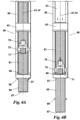
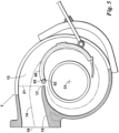
- a turbocharger "T” of this disclosure include a housing 10 containing an inlet or throat section 11 that ends at a downstream end 17 of the tongue 15; a volute 13 that may continuously decrease in area and cross section from an initial cross section 21 of the throat 11; a volute slot 25 located along a midline 23 of the volute 13 into which inlet exhaust gas entering the throat 11 can flow; and a turbine inducer or wheel area 29 exposed to the volute slot 25 and, therefore, the inlet exhaust gas flow.
- the housing 10 includes a dual or two-part vane 40 that effectively extends the inlet throat area farther downstream and, therefore, varies the A/R ratio of the housing 10.
- a single dual vane 40 services the volute 13.
- the vane 40 is configured such that, when fully closed and when fully closed and extended, inlet exhaust gas flowing over the vane 40 is blocked or prevented from entering the volute slot 25 and, therefore, the wheel area 29, until it passes the vane 40.
- the dual vane 40 is comprised of two complementary vanes: a primary vane 50 which pivots and a secondary vane 60 that slides.
- a longitudinal centerline 41 of the dual vane 40 is aligned with a vertical centerline 33 of the volute slot 25.
- the dual vane 40 may be sized widthwise such that it can be received by the volute slot 25 yet still block flow into the slot 25 or can be sized wider than the slot 25. Making the vane 40 wider than slot 25 serves to raise the dual vane 40 higher in the volute 13, thereby decreasing the cross-sectional area above the vane 40.
- a first portion ⁇ 1 of the volute slot 25 is blocked.
- This first portion ⁇ 1 may be equal to the length of the primary vane 50 plus a length of any non-overlapping portion 62 of the secondary vane 60 when in the fully retracted position.
- a second additional portion ⁇ 2 of the volute slot is blocked.
- This second portion ⁇ 2 may be equal to the length of the secondary vane when extended less the length of the non-overlapping portion 62 (when fully retracted).
- the first and second portions ⁇ 1, ⁇ 2 may be equal to the overall length of the vanes 50, 60, respectively.
- the primary or pivoting vane 50 may be located within the housing 10 at, or proximal to, the downstream end 17 of the tongue 15.
- the primary vane 50 effectively extends the throat 11 farther downstream in the volute 13 to provide an extended throat 12 having reduced cross-section area 23A (and therefore a different A/R ratio.
- the primary vane 50 may include a hole 52 at its upstream end 55 that receives a pin or cross shaft 53, permitting the vane 50 to pivot between a fully opened position "O" and a fully closed position "C".
- the shaft 53 may be the upstream end 55 of the vane 50.
- the cross shaft 53 may be located so that it does not affect, or has a negligible effect on, the inlet cross section area 21.
- the cross shaft 53 may be located at the horizontal centerline 14 of the inlet or throat 11 or below the horizontal centerline 14. In some embodiments, the shaft 53 is aligned with the downstream end 17 of the tongue 15.
- the vane 50 may be configured to extend up to about 175°, 180°, or 185° of the turbine volute slot 25 or turbine wheel 29, the center rotational axis 31 of the wheel 29 defining the center point of the vane arc or length. Lengths past 185° may be used - alone or in combination with the secondary vane 60 - but involve more complicated linkages to ensure the vane 50 clears the wheel 29.
- the secondary or sliding vane 60 rides on top of the primary vane 50 in sliding relation to the primary vane 50.
- the vane 60 may be contained in a crosspiece 43.
- the vanes 50, 60 are shaped complementary to one another, with the secondary vane 60 sliding between a fully retracted position "R” and a fully extended position "E.”
- secondary vane 60 may reside in a slot or channel 61 located along a top surface 51 of the primary vane 50.
- Channel 61 may be an exposed channel, meaning that a portion 63 of the top surface 65 of the vane 61 is exposed when in the channel 61.
- the downstream end 67 of the secondary vane 60 may extend past the downstream end 57 of the primary vane 50, effectively serving as the downstream end 47 of the dual vane 40.
- the throat section 12 extends even farther downstream in the volute 13 - that is, past a downstream end 57 of the primary vane 50 up to its fully extended position E - to provide another, further reduced cross-section area 23B during its extension.
- the secondary vane 60 may be configured to extend from the downstream end 57 of the primary vane up to about 270° of the turbine wheel 29 or up to about 360°, therefore functioning as an exhaust brake.
- a stop 69 arranged perpendicular to the longitudinal centerline 41 of the dual vane 40, may be provided to prevent the secondary vane 60 from entering the volute slot 25 during extension and retraction.
- a push rod 70 may be connected to the secondary vane 60.
- the connection to secondary vane 60 may be a pivotal connection 71, for example, with push rod 70 connected at one end 73 to a pin or shaft 75.
- push rod 70 moves axially, it pivots the primary vane 50 about its cross shaft 53 and the push rod's end 73 pivots about it shaft 75.
- the push rod 70 may continue its axial movement, extending the second vane 60 farther downstream.
- An ear 18 may be added to the housing 10 to accommodate the push rod 70, with one end 77 of the push rod 70 lying outside of the ear 18 or housing 10.
- the dual vane 40 may further include a first stop 4569 and a second stop 69.
- the stops 45, 69 may be wider than the volute slot 25 and may be configured to contact the push rod connection 71.
- the primary vane 50 is permitted to pivot between the fully opened and closed positions O, C as well as intermediate positions.
- the secondary vane 50 is permitted to slide into the fully extended position E and block additional portions ⁇ 2 of the slot 25 as the rod 70 moves toward the downstream stop 45.
- the first and second stops 43, 69 may be spaced according to a predetermined length of arc depending, in part, on the amount of full extension desired.
- Computerized control means may be configured to actuate and control the push rod 70 and, therefore, pivot and slide the vanes 50, 60. Changing the location of the primary vane's pivot point 53 or the push rod's connecting point 71 (or both points) affects the amount of pivot and extension.
- the fully opened position O occurs when the dual vane 40 reaches an end of its pivoting movement or travel toward the outer wall 27 of the volute 13. When in this position, the flow of the inlet exhaust gas may be unevenly distributed, with more flow under rather than over the dual vane 40. In some embodiments, in the fully opened position O a portion 41 of the dual vane 40 may contact the wall 27 of the volute 13.
- the dual vane 40 in the fully opened position O, or in a partially opened position C, may lie between a horizontal centerline 14 of the volute 13 and the wall 27, the centerline 14 representing a neutral position. Pivot positions between the centerline 14 and the volute slot 25 may represent partially closed positions.
- a neutral position essentially splits or defines volute 13 into an upper and lower half, with an equal volume of exhaust flowing over and under the vane 40.
- the fully closed position C occurs when the dual vane 40 reaches an end of its pivoting movement or travel toward the volute slot 25.
- the secondary vane remains in its fully retracted position R.
- the dual vane 40 prevents inlet exhaust gas from entering the volute slot 25 until the gas passes the downstream end 57, 67 of the vane 40.
- the secondary vane 60 may then be extended up to its fully extended position E, providing a further reduced cross-section 23B as it extends.
- the A/R ratio of the turbocharger T or housing 10 remains unaltered.
Landscapes
- Engineering & Computer Science (AREA)
- Mechanical Engineering (AREA)
- General Engineering & Computer Science (AREA)
- Chemical & Material Sciences (AREA)
- Combustion & Propulsion (AREA)
- Supercharger (AREA)
Claims (12)
- Turbolader, der aufweist:ein Gehäuse (10) mit einem Spiralraum (13), der einen Einlasskehlenabschnitt (11) und einen Spiralspalt (25) umfasst;eine Doppelschaufel (40), die mit dem Spiralspalt (25) ausgerichtet ist, wobei ein anströmseitiges Ende der Doppelschaufel in der Nähe eines abströmseitigen Endes des Einlasskehlenabschnitts liegt,wobei die Doppelschaufel eine Primärschaufel (50) und eine Sekundärschaufel (60) umfasst, die Sekundärschaufel auf einer der Spiralenwand gegenüberliegenden Oberfläche der Primärschaufel angeordnet ist und komplementär zu der Primärschaufel geformt ist, die Primärschaufel zum Weg- und Hinschwenken von bzw. zu dem Spiralspalt (25) zwischen einer ganz geöffneten Stellung und einer ganz geschlossenen Stellung konfiguriert ist, die Sekundärschaufel zum Verschieben zwischen einer ganz zurückgezogenen Stellung und einer ganz ausgefahrenen Stellung konfiguriert ist;dadurch gekennzeichnet, dass die Sekundärschaufel (60) in der ganz zurückgezogenen Stellung ist, wenn die Primärschaufel (50) zwischen der ganz geöffneten und der ganz geschlossenen Stellung geschwenkt wird;wobei, in der ganz geschlossenen Stellung, ein Teil des Spiralspalts (25) blockiert ist und die Sekundärschaufel (60) aus der ganz zurückgezogenen Stellung ausgefahren sein kann;wobei, wenn die Sekundärschaufel (60) ausgefahren ist, ein zusätzlicher Teil des Spiralspalts (25) blockiert ist.
- Turbolader nach Anspruch 1, dadurch gekennzeichnet, dass der Turbolader ferner aufweist:eine Schubstange (70) mit einem Ende, das schwenkbar mit der Sekundärschaufel (60) verbunden ist, und einem anderen Ende, das außerhalb des Gehäuses (10) liegt;wobei die Schubstange zum Schwenken der Primärschaufel (50) zwischen der ganz geöffneten und geschlossenen Stellung und, wenn die Primärschaufel in der ganz geschlossenen Stellung ist, zum Ausfahren und Zurückziehen der Sekundärschaufel (60) konfiguriert ist.
- Turbolader nach Anspruch 2, dadurch gekennzeichnet, dass der Turbolader ferner aufweist:die Doppelschaufel (40) mit einem anströmseitigen Anschlag und einem abströmseitigen Anschlag;wobei, wenn die Schubstange mit dem anströmseitigen Anschlag in Kontakt ist, die Primärschaufel (50) zwischen der ganz geöffneten und geschlossenen Stellung geschwenkt werden kann;wobei, wenn die Schubstange sich zwischen dem anströmseitigen und dem abströmseitigen Anschlag bewegt, die Sekundärschaufel (60) zwischen der ganz ausgefahrenen und zurückgezogenen Stellung verschoben werden kann, wobei die ganz ausgefahrene Stellung vorliegt, wenn die Schubstange mit dem abströmseitigen Anschlag in Kontakt ist, die ganz zurückgezogene Stellung vorliegt, wenn die Schubstange mit dem anströmseitigen Anschlag in Kontakt ist.
- Turbolader nach Anspruch 3, dadurch gekennzeichnet, dass in einer ganz geschlossenen und ganz ausgefahrenen Stellung die Doppelschaufel (40) einen Teil des Spiralspalts (25) in einem Bereich von 190° bis 270° des Spiralspalts blockiert.
- Turbolader nach Anspruch 3, dadurch gekennzeichnet, dass in einer ganz geschlossenen und ganz ausgefahrenen Stellung die Doppelschaufel (40) einen Teil des Spiralspalts (25) in einem Bereich von 270° bis 360° des Spiralspalts blockiert.
- Turbolader nach Anspruch 3, dadurch gekennzeichnet, dass in einer ganz geschlossenen und ganz ausgefahrenen Stellung die Doppelschaufel (40) 360° des Spiralspalts (25) blockiert.
- Turbolader nach Anspruch 1, dadurch gekennzeichnet, dass ein A/R-Verhältnis des Gehäuses (10) beim Schwenken der Primärschaufel (50) zwischen der ganz geöffneten und geschlossenen Stellung variiert.
- Turbolader nach Anspruch 7, dadurch gekennzeichnet, dass das A/R-Verhältnis des Gehäuses (10) beim Verschieben der Sekundärschaufel (60) zwischen der ganz ausgefahrenen und eingezogenen Stellung variiert.
- Turbolader nach Anspruch 1, dadurch gekennzeichnet, dass der Turbolader ferner aufweist:
eine Auskehlung (61), die auf einer der Spiralenwand gegenüberliegenden Oberfläche der Primärschaufel (50) liegt, wobei mindestens ein Teil der Sekundärschaufel (60) in der Auskehlung liegt. - Turbolader nach Anspruch 1, dadurch gekennzeichnet, dass der Turbolader ferner aufweist:
eine Querachse, wobei die Primärschaufel (50) an ihrem anströmseitigen Ende mit der Querachse verbunden ist. - Turbolader nach Anspruch 1, dadurch gekennzeichnet, dass der Turbolader ferner aufweist:
ein abströmseitiges Ende der Sekundärschaufel (60), das einen Anschlag mit einer Breite umfasst, die größer ist als die des Spiralspalts (25), wobei der Anschlag zum Verhindern, dass das abströmseitige Ende der Sekundärschaufel (60) in den Spiralspalt (25) eintritt, konfiguriert ist. - Verfahren zum fortschreitenden Variieren eines Fläche/Radius-Verhältnisses eines Turboladergehäuses (10), wobei das Turboladergehäuse umfasst:
eine Doppelschaufel (40), die zu einem abströmseitigen Ende eines Einlasskehlenabschnitts (11) des Turboladers hin liegt, wobei die Doppelschaufel aufweist:eine Primärschaufel (50), die zum Schwenken zwischen einer ganz geöffneten Stellung und einer ganz geschlossenen Stellung relativ zu einem Spiralspalt (25) des Gehäuses (10) konfiguriert ist; undeine Sekundärschaufel (60), die auf einer oberen Oberfläche der Primärschaufel (50) angeordnet ist und komplementär zu der Primärschaufel geformt ist, wobei die Sekundärschaufel zum Verschieben zwischen einer ganz zurückgezogenen Stellung und einer ganz ausgefahrenen Stellung relativ zu der Primärschaufel konfiguriert ist;dadurch gekennzeichnet, dass das Verfahren aufweist:Schwenken der Primärschaufel (50) zwischen der ganz geöffneten und der ganz geschlossenen Stellung, wobei die Sekundärschaufel (60) während des Schwenkens in der ganz zurückgezogenen Stellung bleibt; undVerschieben der Sekundärschaufel (60) zwischen der ganz zurückgezogenen und der ganz ausgefahrenen Stellung, wenn die Primärschaufel (50) in der ganz geschlossenen Stellung ist;wobei ein Teil des Spiralspalts (25), der der Primärschaufel (50) gegenüber liegt, blockiert ist, wenn die Primärschaufel (50) in der ganz geschlossenen Stellung ist; undwobei ein zusätzlicher Teil des Spiralspalts (25), der der Sekundärschaufel (60) gegenüberliegt, blockiert ist, wenn die Sekundärschaufel in Richtung auf die ganz ausgefahrene Stellung verschoben wird.
Applications Claiming Priority (1)
| Application Number | Priority Date | Filing Date | Title |
|---|---|---|---|
| US16/280,601 US10801357B2 (en) | 2019-02-20 | 2019-02-20 | Turbocharger with a pivoting sliding vane for progressively variable A/R ratio |
Publications (2)
| Publication Number | Publication Date |
|---|---|
| EP3699412A1 EP3699412A1 (de) | 2020-08-26 |
| EP3699412B1 true EP3699412B1 (de) | 2024-12-04 |
Family
ID=69591550
Family Applications (1)
| Application Number | Title | Priority Date | Filing Date |
|---|---|---|---|
| EP20157218.7A Active EP3699412B1 (de) | 2019-02-20 | 2020-02-13 | Turbolader mit schwenkbarem schiebeflügel für progressiv veränderliches a/r-verhältnis |
Country Status (3)
| Country | Link |
|---|---|
| US (1) | US10801357B2 (de) |
| EP (1) | EP3699412B1 (de) |
| CA (1) | CA3072151C (de) |
Families Citing this family (5)
| Publication number | Priority date | Publication date | Assignee | Title |
|---|---|---|---|---|
| WO2019087970A1 (ja) * | 2017-11-01 | 2019-05-09 | 株式会社Ihi | 遠心圧縮機 |
| JP7139521B2 (ja) * | 2019-04-19 | 2022-09-20 | 三菱重工エンジン&ターボチャージャ株式会社 | 可変容量タービン及び過給機 |
| CN113236607B (zh) * | 2021-06-11 | 2022-06-28 | 浙江理工大学 | 一种大型工程泵蜗壳的设计方法及其蜗壳 |
| CA3232805A1 (en) * | 2021-10-09 | 2023-04-13 | Tim Sundstrom | System and method for pump control based on pump vibrations |
| CN116291772B (zh) * | 2023-03-03 | 2025-12-09 | 宿州博奥捷汽车部件有限公司 | 一种涡轮机叶轮及其加工工艺 |
Family Cites Families (28)
| Publication number | Priority date | Publication date | Assignee | Title |
|---|---|---|---|---|
| US2944786A (en) | 1953-10-15 | 1960-07-12 | Thompson Ramo Wooldridge Inc | Super and subsonic vaneless nozzle |
| US3190068A (en) | 1964-05-14 | 1965-06-22 | Gardner Denver Co | Turbocharger for compressor driving engine |
| US3313518A (en) | 1966-02-25 | 1967-04-11 | Garrett Corp | Turbine control |
| US3363412A (en) | 1966-03-28 | 1968-01-16 | Caterpillar Tractor Co | System for maintaining turbocharger compressor speed |
| US3396534A (en) | 1967-04-20 | 1968-08-13 | Caterpillar Tractor Co | Air impingement nozzle arrangement for a turbocharger compressor and an improved method of employing air impingement |
| GB1426554A (en) * | 1972-04-13 | 1976-03-03 | Cav Ltd | Turbo superchargers for internal combustion engines |
| US4177005A (en) | 1975-09-06 | 1979-12-04 | Maschinenfabrik Augsburg-Nurnberg Aktiengesellschaft (M.A.N.) | Variable-throat spiral duct system for rotary stream-flow machines |
| US4177006A (en) * | 1977-09-29 | 1979-12-04 | The Garrett Corporation | Turbocharger control |
| US4389845A (en) * | 1979-11-20 | 1983-06-28 | Ishikawajima-Harima Jukogyo Kabushiki Kaisha | Turbine casing for turbochargers |
| DE3105179A1 (de) | 1981-02-13 | 1982-09-09 | Volkswagenwerk Ag, 3180 Wolfsburg | "einen verdichter antreibender abgas-turbolader fuer eine mit veraenderlicher last und drehzahl betriebene brennkraftmaschine" |
| US4512714A (en) | 1982-02-16 | 1985-04-23 | Deere & Company | Variable flow turbine |
| FR2528112B1 (fr) * | 1982-06-03 | 1986-04-11 | Peugeot | Dispositif de suralimentation pour moteur a combustion interne |
| US4678397A (en) | 1983-06-15 | 1987-07-07 | Nissan Motor Co., Ltd. | Variable-capacitance radial turbine having swingable tongue member |
| JPS6065207A (ja) | 1983-09-21 | 1985-04-15 | Nissan Motor Co Ltd | 可変容量ラジアルタ−ビン |
| JPS60178931A (ja) * | 1984-02-24 | 1985-09-12 | Nissan Motor Co Ltd | 排気タ−ボチヤ−ジヤの過給圧制御装置 |
| JPS60182321A (ja) * | 1984-02-29 | 1985-09-17 | Nissan Motor Co Ltd | タ−ボチヤ−ジヤの過給圧制御装置 |
| JPS60261904A (ja) | 1984-06-11 | 1985-12-25 | Nissan Motor Co Ltd | 可変容量ラジアルタ−ビン |
| JP3725287B2 (ja) * | 1996-04-25 | 2005-12-07 | アイシン精機株式会社 | 可変容量ターボチャージャ |
| US6158956A (en) | 1998-10-05 | 2000-12-12 | Allied Signal Inc. | Actuating mechanism for sliding vane variable geometry turbine |
| US20060230759A1 (en) | 2005-04-13 | 2006-10-19 | Semrau H A | Variable geometry turbocharger |
| US7481056B2 (en) | 2006-03-30 | 2009-01-27 | Blaylock Jimmy L | Turbocharger with adjustable throat |
| DE102007058246B4 (de) | 2007-12-04 | 2020-01-09 | BMTS Technology GmbH & Co. KG | Aufladeeinrichtung |
| JP4838830B2 (ja) * | 2008-08-28 | 2011-12-14 | 三菱重工業株式会社 | 可変容量排気ガスタービンの製造方法 |
| CN101865032B (zh) | 2009-04-20 | 2014-06-18 | 博格华纳公司 | 具有滑动闸门以及多个蜗壳的简化的可变几何形状涡轮增压器 |
| KR101645518B1 (ko) | 2009-04-20 | 2016-08-05 | 보르그워너 인코퍼레이티드 | 가변 볼류트 유동 체적들을 가지는 단순화된 가변 구조 터보차저 |
| JP5854514B2 (ja) | 2009-08-30 | 2016-02-09 | アーノルド, スティーヴン, ドン.ARNOLD, Steven, Don | 可変渦巻タービン |
| DE102010053951B4 (de) * | 2010-12-09 | 2021-12-09 | Daimler Ag | Turbine für einen Abgasturbolader |
| CA2912855C (en) | 2013-05-24 | 2020-11-17 | Jimmy L. Blaylock | Turbocharger with progressively variable a/r ratio |
-
2019
- 2019-02-20 US US16/280,601 patent/US10801357B2/en active Active
-
2020
- 2020-02-10 CA CA3072151A patent/CA3072151C/en active Active
- 2020-02-13 EP EP20157218.7A patent/EP3699412B1/de active Active
Also Published As
| Publication number | Publication date |
|---|---|
| CA3072151A1 (en) | 2020-08-20 |
| US20200263559A1 (en) | 2020-08-20 |
| EP3699412A1 (de) | 2020-08-26 |
| CA3072151C (en) | 2022-06-21 |
| US10801357B2 (en) | 2020-10-13 |
Similar Documents
| Publication | Publication Date | Title |
|---|---|---|
| EP3699412B1 (de) | Turbolader mit schwenkbarem schiebeflügel für progressiv veränderliches a/r-verhältnis | |
| US10837306B2 (en) | Turbocharger with progressively variable A/R ratio | |
| US4776168A (en) | Variable geometry turbocharger turbine | |
| KR102076638B1 (ko) | 가변 터빈 구조를 구비한 혼류 터보차저 | |
| EP2863032B1 (de) | Zentrifugalverdichter | |
| JP4612719B2 (ja) | 排気ターボチャージャの排気タービン | |
| US10006345B2 (en) | Mixed flow twin scroll turbocharger with single valve | |
| EP1584796B1 (de) | Turbine mit variabler Geometrie | |
| US20110131976A1 (en) | Exhaust gas turbocharger for an internal combustion engine | |
| CN101027491A (zh) | 带再循环的压缩机装置及其方法 | |
| JP2009281197A (ja) | 斜流タービン | |
| EP3480472B1 (de) | Kreiselverdichter für einen turbolader mit druckausgeglichenem, verstellbarem trimmmechanismus | |
| JP2005299660A5 (de) | ||
| US10138744B2 (en) | Turbocharger with variable turbine geometry having grooved guide vanes | |
| WO2011038240A1 (en) | Turbocharger with assist nozzle and adjustable throat | |
| EP1481151B1 (de) | Verbesserte schaufelausführung zur verwendung in turboladern mit variabler geometrie | |
| JP5427900B2 (ja) | 斜流タービン | |
| JP7395002B2 (ja) | タービン及びターボチャージャ | |
| JP7353354B2 (ja) | 遠心圧縮機及びターボチャージャ | |
| JP2008019748A (ja) | ターボ過給機 | |
| EP4717887A1 (de) | Umkreisungsgehäusebehandlung für gasturbinenmotoren | |
| JP7351903B2 (ja) | 遠心圧縮機及びターボチャージャ | |
| JP2022112406A (ja) | 可変容量タービンおよび過給機 |
Legal Events
| Date | Code | Title | Description |
|---|---|---|---|
| PUAI | Public reference made under article 153(3) epc to a published international application that has entered the european phase |
Free format text: ORIGINAL CODE: 0009012 |
|
| STAA | Information on the status of an ep patent application or granted ep patent |
Free format text: STATUS: REQUEST FOR EXAMINATION WAS MADE |
|
| 17P | Request for examination filed |
Effective date: 20200213 |
|
| AK | Designated contracting states |
Kind code of ref document: A1 Designated state(s): AL AT BE BG CH CY CZ DE DK EE ES FI FR GB GR HR HU IE IS IT LI LT LU LV MC MK MT NL NO PL PT RO RS SE SI SK SM TR |
|
| AX | Request for extension of the european patent |
Extension state: BA ME |
|
| RAP1 | Party data changed (applicant data changed or rights of an application transferred) |
Owner name: SWITCHBLADE TURBO LLC |
|
| RIN1 | Information on inventor provided before grant (corrected) |
Inventor name: SWITCHBLADE TURBO LLC |
|
| STAA | Information on the status of an ep patent application or granted ep patent |
Free format text: STATUS: EXAMINATION IS IN PROGRESS |
|
| 17Q | First examination report despatched |
Effective date: 20230104 |
|
| P01 | Opt-out of the competence of the unified patent court (upc) registered |
Effective date: 20230524 |
|
| GRAP | Despatch of communication of intention to grant a patent |
Free format text: ORIGINAL CODE: EPIDOSNIGR1 |
|
| STAA | Information on the status of an ep patent application or granted ep patent |
Free format text: STATUS: GRANT OF PATENT IS INTENDED |
|
| INTG | Intention to grant announced |
Effective date: 20240611 |
|
| GRAS | Grant fee paid |
Free format text: ORIGINAL CODE: EPIDOSNIGR3 |
|
| GRAJ | Information related to disapproval of communication of intention to grant by the applicant or resumption of examination proceedings by the epo deleted |
Free format text: ORIGINAL CODE: EPIDOSDIGR1 |
|
| GRAL | Information related to payment of fee for publishing/printing deleted |
Free format text: ORIGINAL CODE: EPIDOSDIGR3 |
|
| STAA | Information on the status of an ep patent application or granted ep patent |
Free format text: STATUS: EXAMINATION IS IN PROGRESS |
|
| GRAP | Despatch of communication of intention to grant a patent |
Free format text: ORIGINAL CODE: EPIDOSNIGR1 |
|
| STAA | Information on the status of an ep patent application or granted ep patent |
Free format text: STATUS: GRANT OF PATENT IS INTENDED |
|
| GRAA | (expected) grant |
Free format text: ORIGINAL CODE: 0009210 |
|
| STAA | Information on the status of an ep patent application or granted ep patent |
Free format text: STATUS: THE PATENT HAS BEEN GRANTED |
|
| INTC | Intention to grant announced (deleted) | ||
| INTG | Intention to grant announced |
Effective date: 20241021 |
|
| AK | Designated contracting states |
Kind code of ref document: B1 Designated state(s): AL AT BE BG CH CY CZ DE DK EE ES FI FR GB GR HR HU IE IS IT LI LT LU LV MC MK MT NL NO PL PT RO RS SE SI SK SM TR |
|
| RIN1 | Information on inventor provided before grant (corrected) |
Inventor name: BLAYLOCK, JIMMY L. |
|
| REG | Reference to a national code |
Ref country code: CH Ref legal event code: EP |
|
| REG | Reference to a national code |
Ref country code: DE Ref legal event code: R096 Ref document number: 602020042349 Country of ref document: DE |
|
| REG | Reference to a national code |
Ref country code: IE Ref legal event code: FG4D |
|
| REG | Reference to a national code |
Ref country code: LT Ref legal event code: MG9D |
|
| REG | Reference to a national code |
Ref country code: NL Ref legal event code: MP Effective date: 20241204 |
|
| PG25 | Lapsed in a contracting state [announced via postgrant information from national office to epo] |
Ref country code: HR Free format text: LAPSE BECAUSE OF FAILURE TO SUBMIT A TRANSLATION OF THE DESCRIPTION OR TO PAY THE FEE WITHIN THE PRESCRIBED TIME-LIMIT Effective date: 20241204 |
|
| PGFP | Annual fee paid to national office [announced via postgrant information from national office to epo] |
Ref country code: DE Payment date: 20250212 Year of fee payment: 6 |
|
| PG25 | Lapsed in a contracting state [announced via postgrant information from national office to epo] |
Ref country code: FI Free format text: LAPSE BECAUSE OF FAILURE TO SUBMIT A TRANSLATION OF THE DESCRIPTION OR TO PAY THE FEE WITHIN THE PRESCRIBED TIME-LIMIT Effective date: 20241204 |
|
| PG25 | Lapsed in a contracting state [announced via postgrant information from national office to epo] |
Ref country code: BG Free format text: LAPSE BECAUSE OF FAILURE TO SUBMIT A TRANSLATION OF THE DESCRIPTION OR TO PAY THE FEE WITHIN THE PRESCRIBED TIME-LIMIT Effective date: 20241204 |
|
| PG25 | Lapsed in a contracting state [announced via postgrant information from national office to epo] |
Ref country code: ES Free format text: LAPSE BECAUSE OF FAILURE TO SUBMIT A TRANSLATION OF THE DESCRIPTION OR TO PAY THE FEE WITHIN THE PRESCRIBED TIME-LIMIT Effective date: 20241204 |
|
| PG25 | Lapsed in a contracting state [announced via postgrant information from national office to epo] |
Ref country code: NO Free format text: LAPSE BECAUSE OF FAILURE TO SUBMIT A TRANSLATION OF THE DESCRIPTION OR TO PAY THE FEE WITHIN THE PRESCRIBED TIME-LIMIT Effective date: 20250304 |
|
| PG25 | Lapsed in a contracting state [announced via postgrant information from national office to epo] |
Ref country code: LV Free format text: LAPSE BECAUSE OF FAILURE TO SUBMIT A TRANSLATION OF THE DESCRIPTION OR TO PAY THE FEE WITHIN THE PRESCRIBED TIME-LIMIT Effective date: 20241204 Ref country code: GR Free format text: LAPSE BECAUSE OF FAILURE TO SUBMIT A TRANSLATION OF THE DESCRIPTION OR TO PAY THE FEE WITHIN THE PRESCRIBED TIME-LIMIT Effective date: 20250305 |
|
| PGFP | Annual fee paid to national office [announced via postgrant information from national office to epo] |
Ref country code: BE Payment date: 20250212 Year of fee payment: 6 |
|
| PGFP | Annual fee paid to national office [announced via postgrant information from national office to epo] |
Ref country code: GB Payment date: 20250211 Year of fee payment: 6 |
|
| PG25 | Lapsed in a contracting state [announced via postgrant information from national office to epo] |
Ref country code: RS Free format text: LAPSE BECAUSE OF FAILURE TO SUBMIT A TRANSLATION OF THE DESCRIPTION OR TO PAY THE FEE WITHIN THE PRESCRIBED TIME-LIMIT Effective date: 20250304 |
|
| PG25 | Lapsed in a contracting state [announced via postgrant information from national office to epo] |
Ref country code: NL Free format text: LAPSE BECAUSE OF FAILURE TO SUBMIT A TRANSLATION OF THE DESCRIPTION OR TO PAY THE FEE WITHIN THE PRESCRIBED TIME-LIMIT Effective date: 20241204 |
|
| REG | Reference to a national code |
Ref country code: AT Ref legal event code: MK05 Ref document number: 1748384 Country of ref document: AT Kind code of ref document: T Effective date: 20241204 |
|
| PG25 | Lapsed in a contracting state [announced via postgrant information from national office to epo] |
Ref country code: SM Free format text: LAPSE BECAUSE OF FAILURE TO SUBMIT A TRANSLATION OF THE DESCRIPTION OR TO PAY THE FEE WITHIN THE PRESCRIBED TIME-LIMIT Effective date: 20241204 |
|
| PG25 | Lapsed in a contracting state [announced via postgrant information from national office to epo] |
Ref country code: PL Free format text: LAPSE BECAUSE OF FAILURE TO SUBMIT A TRANSLATION OF THE DESCRIPTION OR TO PAY THE FEE WITHIN THE PRESCRIBED TIME-LIMIT Effective date: 20241204 |
|
| PG25 | Lapsed in a contracting state [announced via postgrant information from national office to epo] |
Ref country code: IS Free format text: LAPSE BECAUSE OF FAILURE TO SUBMIT A TRANSLATION OF THE DESCRIPTION OR TO PAY THE FEE WITHIN THE PRESCRIBED TIME-LIMIT Effective date: 20250404 |
|
| PG25 | Lapsed in a contracting state [announced via postgrant information from national office to epo] |
Ref country code: PT Free format text: LAPSE BECAUSE OF FAILURE TO SUBMIT A TRANSLATION OF THE DESCRIPTION OR TO PAY THE FEE WITHIN THE PRESCRIBED TIME-LIMIT Effective date: 20250404 |
|
| PG25 | Lapsed in a contracting state [announced via postgrant information from national office to epo] |
Ref country code: EE Free format text: LAPSE BECAUSE OF FAILURE TO SUBMIT A TRANSLATION OF THE DESCRIPTION OR TO PAY THE FEE WITHIN THE PRESCRIBED TIME-LIMIT Effective date: 20241204 |
|
| PG25 | Lapsed in a contracting state [announced via postgrant information from national office to epo] |
Ref country code: RO Free format text: LAPSE BECAUSE OF FAILURE TO SUBMIT A TRANSLATION OF THE DESCRIPTION OR TO PAY THE FEE WITHIN THE PRESCRIBED TIME-LIMIT Effective date: 20241204 Ref country code: AT Free format text: LAPSE BECAUSE OF FAILURE TO SUBMIT A TRANSLATION OF THE DESCRIPTION OR TO PAY THE FEE WITHIN THE PRESCRIBED TIME-LIMIT Effective date: 20241204 |
|
| PG25 | Lapsed in a contracting state [announced via postgrant information from national office to epo] |
Ref country code: SK Free format text: LAPSE BECAUSE OF FAILURE TO SUBMIT A TRANSLATION OF THE DESCRIPTION OR TO PAY THE FEE WITHIN THE PRESCRIBED TIME-LIMIT Effective date: 20241204 |
|
| PG25 | Lapsed in a contracting state [announced via postgrant information from national office to epo] |
Ref country code: CZ Free format text: LAPSE BECAUSE OF FAILURE TO SUBMIT A TRANSLATION OF THE DESCRIPTION OR TO PAY THE FEE WITHIN THE PRESCRIBED TIME-LIMIT Effective date: 20241204 |
|
| PG25 | Lapsed in a contracting state [announced via postgrant information from national office to epo] |
Ref country code: IT Free format text: LAPSE BECAUSE OF FAILURE TO SUBMIT A TRANSLATION OF THE DESCRIPTION OR TO PAY THE FEE WITHIN THE PRESCRIBED TIME-LIMIT Effective date: 20241204 |
|
| REG | Reference to a national code |
Ref country code: DE Ref legal event code: R097 Ref document number: 602020042349 Country of ref document: DE |
|
| PG25 | Lapsed in a contracting state [announced via postgrant information from national office to epo] |
Ref country code: SE Free format text: LAPSE BECAUSE OF FAILURE TO SUBMIT A TRANSLATION OF THE DESCRIPTION OR TO PAY THE FEE WITHIN THE PRESCRIBED TIME-LIMIT Effective date: 20241204 |
|
| PG25 | Lapsed in a contracting state [announced via postgrant information from national office to epo] |
Ref country code: MC Free format text: LAPSE BECAUSE OF FAILURE TO SUBMIT A TRANSLATION OF THE DESCRIPTION OR TO PAY THE FEE WITHIN THE PRESCRIBED TIME-LIMIT Effective date: 20241204 |
|
| REG | Reference to a national code |
Ref country code: CH Ref legal event code: PL |
|
| PG25 | Lapsed in a contracting state [announced via postgrant information from national office to epo] |
Ref country code: DK Free format text: LAPSE BECAUSE OF FAILURE TO SUBMIT A TRANSLATION OF THE DESCRIPTION OR TO PAY THE FEE WITHIN THE PRESCRIBED TIME-LIMIT Effective date: 20241204 |
|
| PLBE | No opposition filed within time limit |
Free format text: ORIGINAL CODE: 0009261 |
|
| STAA | Information on the status of an ep patent application or granted ep patent |
Free format text: STATUS: NO OPPOSITION FILED WITHIN TIME LIMIT |
|
| PG25 | Lapsed in a contracting state [announced via postgrant information from national office to epo] |
Ref country code: LU Free format text: LAPSE BECAUSE OF NON-PAYMENT OF DUE FEES Effective date: 20250213 |
|
| PG25 | Lapsed in a contracting state [announced via postgrant information from national office to epo] |
Ref country code: CH Free format text: LAPSE BECAUSE OF NON-PAYMENT OF DUE FEES Effective date: 20250228 |
|
| 26N | No opposition filed |
Effective date: 20250905 |
|
| PG25 | Lapsed in a contracting state [announced via postgrant information from national office to epo] |
Ref country code: FR Free format text: LAPSE BECAUSE OF NON-PAYMENT OF DUE FEES Effective date: 20250228 |
|
| PG25 | Lapsed in a contracting state [announced via postgrant information from national office to epo] |
Ref country code: IE Free format text: LAPSE BECAUSE OF NON-PAYMENT OF DUE FEES Effective date: 20250213 |