EP3696352B1 - Schlüssel für einen schliesszylinder - Google Patents
Schlüssel für einen schliesszylinder Download PDFInfo
- Publication number
- EP3696352B1 EP3696352B1 EP20154080.4A EP20154080A EP3696352B1 EP 3696352 B1 EP3696352 B1 EP 3696352B1 EP 20154080 A EP20154080 A EP 20154080A EP 3696352 B1 EP3696352 B1 EP 3696352B1
- Authority
- EP
- European Patent Office
- Prior art keywords
- locking
- key
- inclination
- locking recesses
- recesses
- Prior art date
- Legal status (The legal status is an assumption and is not a legal conclusion. Google has not performed a legal analysis and makes no representation as to the accuracy of the status listed.)
- Active
Links
Images

Classifications
-
- E—FIXED CONSTRUCTIONS
- E05—LOCKS; KEYS; WINDOW OR DOOR FITTINGS; SAFES
- E05B—LOCKS; ACCESSORIES THEREFOR; HANDCUFFS
- E05B19/00—Keys; Accessories therefor
- E05B19/0017—Key profiles
- E05B19/0023—Key profiles characterized by variation of the contact surface between the key and the tumbler pins or plates
-
- E—FIXED CONSTRUCTIONS
- E05—LOCKS; KEYS; WINDOW OR DOOR FITTINGS; SAFES
- E05B—LOCKS; ACCESSORIES THEREFOR; HANDCUFFS
- E05B19/00—Keys; Accessories therefor
- E05B19/0017—Key profiles
- E05B19/0035—Key profiles characterized by longitudinal bit variations
Definitions
- the invention relates to a key for a locking cylinder with a series of locking recesses arranged in a shaft, wherein the locking recesses are each delimited by flank contours and have support surfaces for supporting locking elements of the locking cylinder, wherein the angle of inclination of the flank contours varies over the series of locking recesses.
- a locking cylinder of the type mentioned above is known, for example, from GB 1 284 914 A In this locking cylinder, two locking recesses have a flatter angle of inclination than the other locking recesses.
- the DE 10 2004 009 166 A1 discloses a key in which recesses for operating pin tumblers have a cutout. The pin tumblers thus rest on the edges of the cutouts. When the key is removed, the associated pin tumblers are moved simultaneously. The speed of movement of the pin tumblers in the recesses with the cutouts is determined by the contour of the tip of the pin tumblers.
- the WO 2018/188971 A1 discloses a key in which locking recesses have different angles of inclination of the flank contours. Deep locking recesses have greater angles of inclination than flatter locking recesses. This is intended to create sufficient variation options and make copying more difficult.
- a locking cylinder with a key is, for example, from the WO 2015/114172 A1 known.
- the locking cylinder has several locking elements, which are spaced apart from one another at different distances. Locking recesses in the key for controlling the locking elements are spaced apart at the same distances as the locking elements. This is to prevent the insertion force from increasing from locking element to locking element when inserting the key into the locking cylinder.
- the EP 2 281 985 A2 A locking cylinder with a key has become known in which the distances between individual locking elements vary.
- the key bit control edges for controlling the locking elements have the same distances as the contact surfaces on the locking elements.
- This locking cylinder is intended to make unauthorized unlocking using a so-called picking method more difficult.
- a key for a locking cylinder has become known in which locking recesses are provided for controlling the locking elements of the locking cylinder.
- the locking recesses have locking surfaces to support the locking element.
- the transitions of the beveled flanks adjacent to the locking surfaces have concave, rounded sliding surfaces. This is intended to prevent snagging when operating the locking cylinder.
- the disadvantage of the known keys is that the key is held by all locking elements simultaneously when inserted, as the locking elements usually have the same dimensions at their ends facing the locking recesses.
- the key is held by all locking elements simultaneously, which means that a high withdrawal force is required to remove it from the locking cylinder, as all the frictional forces of the individual locking elements must be released simultaneously.
- the invention is based on the problem of developing a key of the type mentioned at the beginning in such a way that the withdrawal force is kept as low as possible when the key is completely inserted into the locking cylinder.
- This problem is solved according to the invention in that an increase in the angle of inclination is formed in a predetermined step sequence.
- This design means that the individual locking recesses no longer have the same angle of inclination of the flank contours.
- the variance of the angle of inclination means that the locking elements experience different accelerations when the key is removed. This keeps the withdrawal force particularly low when the key is fully inserted into the locking cylinder. A slowly increasing force curve when the key is removed can be easily achieved because the angle of inclination increases in a predetermined step sequence.
- the different angles of inclination of the flank contours can be easily created in limited space conditions if the angle of inclination of a flat locking recess is smaller than the angle of inclination of a deep locking recess. Since locking elements penetrating flat locking recesses only have to be moved a short distance, a flatter angle of inclination is sufficient to control the locking element. This means that locking elements penetrating flat locking recesses only experience a slight acceleration when the key is removed. This keeps the key's withdrawal force particularly low.
- the invention contributes to further equalizing the pull-off force if the increase in the angle of inclination of the flank contours is designed as a continuous series.
- the locking members can initially be released with little effort and then accelerated if the angles of inclination of the flank contours are not constant, so that the flank contour has a different angle of inclination at the deepest point of the locking recess than at the flattest point.
- the invention contributes to further reducing the key withdrawal force if the support surfaces of individual locking recesses have different widths.
- the variation in the widths of the locking recesses prevents the locking elements from being activated simultaneously by the different locking recesses. Instead, the variation in the widths in the locking cylinder causes the locking elements to be moved in a sequence, since the locking elements each have the same dimensions at their ends facing the locking recesses.
- a particularly uniform control of the locking elements when the key is removed can be achieved if the widths of the locking recesses increase in a predetermined step sequence. This means that one locking element after the other is released when the key is removed.
- a particularly low withdrawal force can be achieved if all widths of the locking recesses or the flank contours of all locking recesses are variable across the row of locking recesses.
- the manufacture of the variable locking recesses is particularly cost-effective if the shaft is rectangular in cross-section and has a key breast and a key back on its narrow sides and if the locking recesses are arranged in the key breast.
- the locking recesses are accessible during manufacture from the broad sides of the shaft using a milling or cutting tool and can penetrate the shaft. This makes it particularly easy to produce the flank contours with great variability.
- Figure 1 shows a longitudinal section through a portion of a locking cylinder 1 with a housing 2 and a core 3 arranged rotatably therein.
- the locking cylinder 1 also has a locking bit 4 connected to the core 3 in a rotationally fixed manner.
- a key 6 for locking the locking cylinder 1 is inserted into a locking channel 5 of the core 3.
- the locking cylinder 1 has locking elements 7 designed as pin tumblers for optionally blocking or releasing the movement of the core 3.
- the locking elements 7 sense locking recesses 9 arranged in a shaft 8 of the key 6 and each have the same dimensions at their ends facing the locking recesses 9. Furthermore, the locking elements 7 are arranged at the same distance from one another.
- the locking elements 7 each have a core pin 10 guided in the core 3 and a housing pin 11 guided in the housing 2 and a spring element 12 for pre-tensioning the housing pin 11 against the core pin 10.
- the parting planes of the housing pins 11 and the core pins 10 of all locking elements 7 lie in the parting plane between the housing 2 and the core 3, so that the core 3 can be rotated together with the locking bit 4 relative to the housing 2.
- Figure 2 shows in a greatly enlarged view the key 6 with the locking recesses 9a - 9e and the locking elements 7 of the locking cylinder 1 in the abutting areas. It can be seen that the locking recesses 9a - 9e each have support surfaces 13a - 13e and the core pins 10 each have
- Ends are designed in a truncated cone shape for support on the support surfaces 13a - 13e.
- One of the support surfaces 13e has this width.
- the remaining support surfaces 13a - 13d are widened by a specified step sequence compared to the standard width and are marked with x+1 to x+4. With a step sequence of 0.1 mm, the standard width of the support surface 13a with the marking x+1 is widened by 0.1 mm and the support surface 13b with the marking x+4 is widened by 0.4 mm.
- the locking element 7 that interacts with the locking recess 9b marked with x+4 is activated last. This overcomes the static friction forces of the individual locking elements 7 one after the other.
- the locking recesses 9a - 9e also have flank contours 14a - 14e with angles of inclination A1 to A5.
- the angles of inclination A1 - A5 vary across the series of locking recesses 9a - 9e. In the embodiment shown, the angle of inclination A5 of a flat locking recess 9e is smaller than the angle of inclination A4 of a locking recess 9d that is machined deep into the key 6.
- Figure 3 shows a further embodiment of a key 6' which extends from the Figure 2 only differs in that the step sequences are formed as a continuous series over the locking recesses 9a' - 9e'.
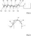
- Figure 4 shows a portion of another embodiment of the key 6", which differs from the Figure 1 differs in that flank contours 14a" - 14e" of the locking recesses 9a" - 9e” have different angles of inclination A1" to A5" in their areas abutting the free ends of the locking elements 7.
- the angles of inclination A1" - A5" increase over the row of locking recesses 9a" - 9e” so that the angle of inclination A5" is greater than the angle of inclination A1".
- the locking elements 7 therefore experience different accelerations when the key 6" is removed.
- the locking recesses 9a" - 9e" of the key 6" from Figure 4 also have different widths of support surfaces 13", as shown in the Figures 2 or 3 shown.
- Figure 5 shows greatly enlarged one of the locking recesses 9a" from Figure 4 with the adjacent area of one of the locking elements 7. It can be seen that the flank contour 14a" is not constant, so that the flank contour 14a" has the inclination angle A1" at the deepest point, the inclination angle B1 in the middle area and the inclination angle C1 in the flattest area.
Landscapes
- Lock And Its Accessories (AREA)
- Chair Legs, Seat Parts, And Backrests (AREA)
Priority Applications (2)
| Application Number | Priority Date | Filing Date | Title |
|---|---|---|---|
| SI202030545T SI3696352T1 (sl) | 2019-02-14 | 2020-01-28 | Ključ za zaklepni cilinder |
| HRP20241727TT HRP20241727T1 (hr) | 2019-02-14 | 2020-01-28 | Ključ za cilindar brave |
Applications Claiming Priority (1)
| Application Number | Priority Date | Filing Date | Title |
|---|---|---|---|
| DE102019201995.1A DE102019201995A1 (de) | 2019-02-14 | 2019-02-14 | SCHLÜSSEL FÜR EINEN SCHLIEßZYLINDER |
Publications (2)
| Publication Number | Publication Date |
|---|---|
| EP3696352A1 EP3696352A1 (de) | 2020-08-19 |
| EP3696352B1 true EP3696352B1 (de) | 2024-10-30 |
Family
ID=69374221
Family Applications (1)
| Application Number | Title | Priority Date | Filing Date |
|---|---|---|---|
| EP20154080.4A Active EP3696352B1 (de) | 2019-02-14 | 2020-01-28 | Schlüssel für einen schliesszylinder |
Country Status (9)
| Country | Link |
|---|---|
| EP (1) | EP3696352B1 (pl) |
| DE (1) | DE102019201995A1 (pl) |
| DK (1) | DK3696352T3 (pl) |
| ES (1) | ES3000059T3 (pl) |
| FI (1) | FI3696352T3 (pl) |
| HR (1) | HRP20241727T1 (pl) |
| HU (1) | HUE069321T2 (pl) |
| PL (1) | PL3696352T3 (pl) |
| SI (1) | SI3696352T1 (pl) |
Family Cites Families (7)
| Publication number | Priority date | Publication date | Assignee | Title |
|---|---|---|---|---|
| DE1813821A1 (de) * | 1968-12-11 | 1970-07-02 | Eaton Yale & Towne Gmbh | Schluessel fuer Schliesszylinder |
| DE29818143U1 (de) | 1998-10-10 | 2000-02-17 | Bks Gmbh, 42549 Velbert | Sicherheitsschlüssel |
| DE102004009166B4 (de) * | 2004-02-25 | 2009-10-22 | Aug. Winkhaus Gmbh & Co. Kg | Schlüssel für einen Schließzylinder |
| AT506700B1 (de) * | 2008-07-15 | 2009-11-15 | Evva Werke | Flachschlüssel |
| AT508869B1 (de) | 2009-08-06 | 2013-07-15 | Evva Sicherheitstechnologie | Schlüssel und zylinderschloss |
| EP3117056B1 (de) | 2014-02-03 | 2019-04-10 | Huf Hülsbeck & Fürst GmbH & Co. KG | Schliesszylinder für eine schlossvorrichtung |
| AT519857B1 (de) * | 2017-04-11 | 2021-04-15 | Evva Sicherheitstechnologie | Schlüssel und Zylinderschloss |
-
2019
- 2019-02-14 DE DE102019201995.1A patent/DE102019201995A1/de not_active Withdrawn
-
2020
- 2020-01-28 DK DK20154080.4T patent/DK3696352T3/da active
- 2020-01-28 FI FIEP20154080.4T patent/FI3696352T3/en active
- 2020-01-28 SI SI202030545T patent/SI3696352T1/sl unknown
- 2020-01-28 PL PL20154080.4T patent/PL3696352T3/pl unknown
- 2020-01-28 HR HRP20241727TT patent/HRP20241727T1/hr unknown
- 2020-01-28 EP EP20154080.4A patent/EP3696352B1/de active Active
- 2020-01-28 ES ES20154080T patent/ES3000059T3/es active Active
- 2020-01-28 HU HUE20154080A patent/HUE069321T2/hu unknown
Also Published As
| Publication number | Publication date |
|---|---|
| EP3696352A1 (de) | 2020-08-19 |
| ES3000059T3 (en) | 2025-02-27 |
| HUE069321T2 (hu) | 2025-03-28 |
| PL3696352T3 (pl) | 2025-01-13 |
| SI3696352T1 (sl) | 2025-02-28 |
| HRP20241727T1 (hr) | 2025-02-28 |
| DK3696352T3 (da) | 2024-12-09 |
| FI3696352T3 (en) | 2024-12-10 |
| DE102019201995A1 (de) | 2020-08-20 |
Similar Documents
| Publication | Publication Date | Title |
|---|---|---|
| DE8035193U1 (de) | Schluessel fuer einen schliesszylinder | |
| DE3032203A1 (de) | Zylinderschloss mit zugehoerigem flachschluessel | |
| EP3922788B1 (de) | Schlüsselrohling und schlüssel zum betätigen eines scheibenzylinders sowie verfahren zum herstellen eines solchen schlüsselrohlings und schlüssels | |
| DE3517660A1 (de) | Sicherheitsschloss | |
| DE202009011052U1 (de) | Aus Schlüssel und Schließzylinder bestehende Schließvorrichtung | |
| EP3696352B1 (de) | Schlüssel für einen schliesszylinder | |
| EP3610103B1 (de) | Schlüssel und system aus schlüssel und zylinderschloss | |
| EP3696351B1 (de) | Schlüssel für einen schliesszylinder | |
| DE19741118A1 (de) | Modifizierter Schließzylinder | |
| EP1726749B1 (de) | Schließzylinder mit einem Schlüssel | |
| DE4037358C2 (de) | Zylinderschloß | |
| EP3696353A1 (de) | Schliesseinrichtung mit einem schlüssel und einem schliesszylinder | |
| EP2149657B1 (de) | Schlüssel für einen Schließzylinder und Rohling für einen solchen Schlüssel | |
| EP1806466A2 (de) | Zylinderschloss mit Schieber sowie Flachschlüssel mit Steuerrippe | |
| EP2221436A2 (de) | Schlüssel für einen Schließzylinder | |
| DE102017121604A1 (de) | Gesicherte Vorrichtung zum Sperren eines funktionswesentlichen Bauteils eines Kraftfahrzeugs | |
| EP1577469B1 (de) | Schlüssel | |
| EP3280854B1 (de) | Schlüssel, schlüsselrohling und schliesssystem mit einem solchen schlüssel und einem zugehörigen schliesszylinder | |
| EP3971371B1 (de) | Schloss-schlüssel-system | |
| EP1746226B1 (de) | Schlüssel | |
| EP4370763B1 (de) | Schlüssel oder schlüsselrohling, herstellungsverfahren und schliesssystem | |
| EP2765260A2 (de) | Schließzylinder | |
| EP3412849B1 (de) | Schlüssel für einen schliesszylinder und schliesszylinder für einen solchen schlüssel | |
| EP4379173A1 (de) | Schliesszylinder | |
| EP3095931B1 (de) | Schliesszylinder und schliesssystem mit einem solchen schliesszylinder |
Legal Events
| Date | Code | Title | Description |
|---|---|---|---|
| REG | Reference to a national code |
Ref country code: HR Ref legal event code: TUEP Ref document number: P20241727T Country of ref document: HR |
|
| PUAI | Public reference made under article 153(3) epc to a published international application that has entered the european phase |
Free format text: ORIGINAL CODE: 0009012 |
|
| STAA | Information on the status of an ep patent application or granted ep patent |
Free format text: STATUS: THE APPLICATION HAS BEEN PUBLISHED |
|
| AK | Designated contracting states |
Kind code of ref document: A1 Designated state(s): AL AT BE BG CH CY CZ DE DK EE ES FI FR GB GR HR HU IE IS IT LI LT LU LV MC MK MT NL NO PL PT RO RS SE SI SK SM TR |
|
| AX | Request for extension of the european patent |
Extension state: BA ME |
|
| STAA | Information on the status of an ep patent application or granted ep patent |
Free format text: STATUS: REQUEST FOR EXAMINATION WAS MADE |
|
| 17P | Request for examination filed |
Effective date: 20201001 |
|
| RBV | Designated contracting states (corrected) |
Designated state(s): AL AT BE BG CH CY CZ DE DK EE ES FI FR GB GR HR HU IE IS IT LI LT LU LV MC MK MT NL NO PL PT RO RS SE SI SK SM TR |
|
| P01 | Opt-out of the competence of the unified patent court (upc) registered |
Effective date: 20230515 |
|
| REG | Reference to a national code |
Ref country code: DE Ref legal event code: R079 Free format text: PREVIOUS MAIN CLASS: E05B0019060000 Ipc: E05B0019000000 Ref document number: 502020009586 Country of ref document: DE |
|
| GRAP | Despatch of communication of intention to grant a patent |
Free format text: ORIGINAL CODE: EPIDOSNIGR1 |
|
| STAA | Information on the status of an ep patent application or granted ep patent |
Free format text: STATUS: GRANT OF PATENT IS INTENDED |
|
| RIC1 | Information provided on ipc code assigned before grant |
Ipc: E05B 19/00 20060101AFI20240528BHEP |
|
| INTG | Intention to grant announced |
Effective date: 20240619 |
|
| GRAS | Grant fee paid |
Free format text: ORIGINAL CODE: EPIDOSNIGR3 |
|
| GRAA | (expected) grant |
Free format text: ORIGINAL CODE: 0009210 |
|
| STAA | Information on the status of an ep patent application or granted ep patent |
Free format text: STATUS: THE PATENT HAS BEEN GRANTED |
|
| AK | Designated contracting states |
Kind code of ref document: B1 Designated state(s): AL AT BE BG CH CY CZ DE DK EE ES FI FR GB GR HR HU IE IS IT LI LT LU LV MC MK MT NL NO PL PT RO RS SE SI SK SM TR |
|
| REG | Reference to a national code |
Ref country code: GB Ref legal event code: FG4D Free format text: NOT ENGLISH |
|
| REG | Reference to a national code |
Ref country code: CH Ref legal event code: EP |
|
| REG | Reference to a national code |
Ref country code: IE Ref legal event code: FG4D Free format text: LANGUAGE OF EP DOCUMENT: GERMAN |
|
| REG | Reference to a national code |
Ref country code: DE Ref legal event code: R096 Ref document number: 502020009586 Country of ref document: DE |
|
| RAP4 | Party data changed (patent owner data changed or rights of a patent transferred) |
Owner name: AUG. WINKHAUS SE & CO. KG |
|
| REG | Reference to a national code |
Ref country code: DK Ref legal event code: T3 Effective date: 20241206 |
|
| REG | Reference to a national code |
Ref country code: FI Ref legal event code: FGE |
|
| REG | Reference to a national code |
Ref country code: NL Ref legal event code: FP |
|
| REG | Reference to a national code |
Ref country code: HR Ref legal event code: ODRP Ref document number: P20241727T Country of ref document: HR Payment date: 20250122 Year of fee payment: 6 |
|
| PGFP | Annual fee paid to national office [announced via postgrant information from national office to epo] |
Ref country code: NL Payment date: 20250122 Year of fee payment: 6 |
|
| REG | Reference to a national code |
Ref country code: LT Ref legal event code: MG9D |
|
| REG | Reference to a national code |
Ref country code: ES Ref legal event code: FG2A Ref document number: 3000059 Country of ref document: ES Kind code of ref document: T3 Effective date: 20250227 |
|
| PGFP | Annual fee paid to national office [announced via postgrant information from national office to epo] |
Ref country code: HU Payment date: 20250128 Year of fee payment: 6 |
|
| REG | Reference to a national code |
Ref country code: HR Ref legal event code: T1PR Ref document number: P20241727 Country of ref document: HR |
|
| REG | Reference to a national code |
Ref country code: HU Ref legal event code: AG4A Ref document number: E069321 Country of ref document: HU |
|
| PG25 | Lapsed in a contracting state [announced via postgrant information from national office to epo] |
Ref country code: PT Free format text: LAPSE BECAUSE OF FAILURE TO SUBMIT A TRANSLATION OF THE DESCRIPTION OR TO PAY THE FEE WITHIN THE PRESCRIBED TIME-LIMIT Effective date: 20250228 Ref country code: IS Free format text: LAPSE BECAUSE OF FAILURE TO SUBMIT A TRANSLATION OF THE DESCRIPTION OR TO PAY THE FEE WITHIN THE PRESCRIBED TIME-LIMIT Effective date: 20250228 |
|
| PGFP | Annual fee paid to national office [announced via postgrant information from national office to epo] |
Ref country code: DE Payment date: 20250120 Year of fee payment: 6 Ref country code: HR Payment date: 20250122 Year of fee payment: 6 |
|
| PGFP | Annual fee paid to national office [announced via postgrant information from national office to epo] |
Ref country code: DK Payment date: 20250122 Year of fee payment: 6 Ref country code: FI Payment date: 20250121 Year of fee payment: 6 |
|
| PG25 | Lapsed in a contracting state [announced via postgrant information from national office to epo] |
Ref country code: BG Free format text: LAPSE BECAUSE OF FAILURE TO SUBMIT A TRANSLATION OF THE DESCRIPTION OR TO PAY THE FEE WITHIN THE PRESCRIBED TIME-LIMIT Effective date: 20241030 |
|
| PGFP | Annual fee paid to national office [announced via postgrant information from national office to epo] |
Ref country code: ES Payment date: 20250214 Year of fee payment: 6 |
|
| PG25 | Lapsed in a contracting state [announced via postgrant information from national office to epo] |
Ref country code: NO Free format text: LAPSE BECAUSE OF FAILURE TO SUBMIT A TRANSLATION OF THE DESCRIPTION OR TO PAY THE FEE WITHIN THE PRESCRIBED TIME-LIMIT Effective date: 20250130 |
|
| PG25 | Lapsed in a contracting state [announced via postgrant information from national office to epo] |
Ref country code: LV Free format text: LAPSE BECAUSE OF FAILURE TO SUBMIT A TRANSLATION OF THE DESCRIPTION OR TO PAY THE FEE WITHIN THE PRESCRIBED TIME-LIMIT Effective date: 20241030 Ref country code: GR Free format text: LAPSE BECAUSE OF FAILURE TO SUBMIT A TRANSLATION OF THE DESCRIPTION OR TO PAY THE FEE WITHIN THE PRESCRIBED TIME-LIMIT Effective date: 20250131 |
|
| PGFP | Annual fee paid to national office [announced via postgrant information from national office to epo] |
Ref country code: SI Payment date: 20250120 Year of fee payment: 6 Ref country code: BE Payment date: 20250121 Year of fee payment: 6 Ref country code: CH Payment date: 20250201 Year of fee payment: 6 Ref country code: AT Payment date: 20250120 Year of fee payment: 6 |
|
| PGFP | Annual fee paid to national office [announced via postgrant information from national office to epo] |
Ref country code: PL Payment date: 20250117 Year of fee payment: 6 Ref country code: FR Payment date: 20250122 Year of fee payment: 6 Ref country code: CZ Payment date: 20250117 Year of fee payment: 6 |
|
| PGFP | Annual fee paid to national office [announced via postgrant information from national office to epo] |
Ref country code: GB Payment date: 20250123 Year of fee payment: 6 Ref country code: IT Payment date: 20250228 Year of fee payment: 6 |
|
| PG25 | Lapsed in a contracting state [announced via postgrant information from national office to epo] |
Ref country code: RS Free format text: LAPSE BECAUSE OF FAILURE TO SUBMIT A TRANSLATION OF THE DESCRIPTION OR TO PAY THE FEE WITHIN THE PRESCRIBED TIME-LIMIT Effective date: 20250130 |
|
| PGFP | Annual fee paid to national office [announced via postgrant information from national office to epo] |
Ref country code: TR Payment date: 20250124 Year of fee payment: 6 |
|
| PG25 | Lapsed in a contracting state [announced via postgrant information from national office to epo] |
Ref country code: SM Free format text: LAPSE BECAUSE OF FAILURE TO SUBMIT A TRANSLATION OF THE DESCRIPTION OR TO PAY THE FEE WITHIN THE PRESCRIBED TIME-LIMIT Effective date: 20241030 |
|
| PG25 | Lapsed in a contracting state [announced via postgrant information from national office to epo] |
Ref country code: EE Free format text: LAPSE BECAUSE OF FAILURE TO SUBMIT A TRANSLATION OF THE DESCRIPTION OR TO PAY THE FEE WITHIN THE PRESCRIBED TIME-LIMIT Effective date: 20241030 |
|
| PG25 | Lapsed in a contracting state [announced via postgrant information from national office to epo] |
Ref country code: RO Free format text: LAPSE BECAUSE OF FAILURE TO SUBMIT A TRANSLATION OF THE DESCRIPTION OR TO PAY THE FEE WITHIN THE PRESCRIBED TIME-LIMIT Effective date: 20241030 |
|
| PG25 | Lapsed in a contracting state [announced via postgrant information from national office to epo] |
Ref country code: SK Free format text: LAPSE BECAUSE OF FAILURE TO SUBMIT A TRANSLATION OF THE DESCRIPTION OR TO PAY THE FEE WITHIN THE PRESCRIBED TIME-LIMIT Effective date: 20241030 |
|
| REG | Reference to a national code |
Ref country code: DE Ref legal event code: R097 Ref document number: 502020009586 Country of ref document: DE |
|
| REG | Reference to a national code |
Ref country code: DE Ref legal event code: R081 Ref document number: 502020009586 Country of ref document: DE Owner name: AUG. WINKHAUS SE, DE Free format text: FORMER OWNER: AUG. WINKHAUS GMBH & CO. KG, 48291 TELGTE, DE |
|
| PLBE | No opposition filed within time limit |
Free format text: ORIGINAL CODE: 0009261 |
|
| STAA | Information on the status of an ep patent application or granted ep patent |
Free format text: STATUS: NO OPPOSITION FILED WITHIN TIME LIMIT |
|
| PG25 | Lapsed in a contracting state [announced via postgrant information from national office to epo] |
Ref country code: SE Free format text: LAPSE BECAUSE OF FAILURE TO SUBMIT A TRANSLATION OF THE DESCRIPTION OR TO PAY THE FEE WITHIN THE PRESCRIBED TIME-LIMIT Effective date: 20241030 |
|
| PG25 | Lapsed in a contracting state [announced via postgrant information from national office to epo] |
Ref country code: LU Free format text: LAPSE BECAUSE OF NON-PAYMENT OF DUE FEES Effective date: 20250128 Ref country code: MC Free format text: LAPSE BECAUSE OF FAILURE TO SUBMIT A TRANSLATION OF THE DESCRIPTION OR TO PAY THE FEE WITHIN THE PRESCRIBED TIME-LIMIT Effective date: 20241030 |
|
| 26N | No opposition filed |
Effective date: 20250731 |
|
| PG25 | Lapsed in a contracting state [announced via postgrant information from national office to epo] |
Ref country code: IE Free format text: LAPSE BECAUSE OF NON-PAYMENT OF DUE FEES Effective date: 20250128 |
|
| REG | Reference to a national code |
Ref country code: CH Ref legal event code: U11 Free format text: ST27 STATUS EVENT CODE: U-0-0-U10-U11 (AS PROVIDED BY THE NATIONAL OFFICE) Effective date: 20260201 |