EP3695044B1 - Wäschepflegegerät mit einer haltevorrichtung - Google Patents
Wäschepflegegerät mit einer haltevorrichtung Download PDFInfo
- Publication number
- EP3695044B1 EP3695044B1 EP18779353.4A EP18779353A EP3695044B1 EP 3695044 B1 EP3695044 B1 EP 3695044B1 EP 18779353 A EP18779353 A EP 18779353A EP 3695044 B1 EP3695044 B1 EP 3695044B1
- Authority
- EP
- European Patent Office
- Prior art keywords
- door
- receptacle
- appliance
- edge
- laundry care
- Prior art date
- Legal status (The legal status is an assumption and is not a legal conclusion. Google has not performed a legal analysis and makes no representation as to the accuracy of the status listed.)
- Active
Links
Images



Classifications
-
- D—TEXTILES; PAPER
- D06—TREATMENT OF TEXTILES OR THE LIKE; LAUNDERING; FLEXIBLE MATERIALS NOT OTHERWISE PROVIDED FOR
- D06F—LAUNDERING, DRYING, IRONING, PRESSING OR FOLDING TEXTILE ARTICLES
- D06F39/00—Details of washing machines not specific to a single type of machines covered by groups D06F9/00 - D06F27/00
- D06F39/12—Casings; Tubs
- D06F39/14—Doors or covers; Securing means therefor
-
- D—TEXTILES; PAPER
- D06—TREATMENT OF TEXTILES OR THE LIKE; LAUNDERING; FLEXIBLE MATERIALS NOT OTHERWISE PROVIDED FOR
- D06F—LAUNDERING, DRYING, IRONING, PRESSING OR FOLDING TEXTILE ARTICLES
- D06F39/00—Details of washing machines not specific to a single type of machines covered by groups D06F9/00 - D06F27/00
- D06F39/12—Casings; Tubs
Definitions
- the present invention relates to a laundry care device with a holding device.
- a conventional laundry care appliance laundry is introduced into a laundry drum of the laundry care appliance through an opening in the appliance.
- the device opening is closed by a device door.
- conventional laundry care appliances have a door device which is designed to automatically open or close the appliance door.
- Conventional door devices can include electromechanical components that are designed to support an appliance door lock or an appliance door opening. Here, the assembly of the locking device or electromechanical components is often challenging due to the limited space available.
- EP 1 418 266 A2 discloses a device for locking a shutter door of a washing machine.
- WO 2006/122842 A1 discloses a laundry care device with a device door for closing a device opening of the laundry care device.
- the object on which the invention is based is to specify a laundry care device with advantageously built-in components for locking the appliance door or for opening the appliance door. This object is achieved by the subject matter with the features according to the independent claim. Advantageous embodiments are the subject matter of the dependent claims, the description and the drawings.
- the object of the invention is provided by a laundry care device with a device door for closing a device opening of the laundry care device, a device wall which has a door holding opening, and a holding device which is designed to hold a door device for opening or closing the device door, the holding device is inserted into the door holding opening, released, the holding device having a first receptacle into which a first edge of the device wall delimiting the door holding opening engages, the holding device being a the first receptacle has a second receptacle opposite the first edge, in which a second edge of the device wall that delimits the door holding opening and which is opposite the first edge engages, and wherein the holding device has a deformable latching arm which is arranged and formed on the first receptacle, in a fastening position in the door holding opening to attach the inserted holding device latching on the device wall.
- the door device is designed in particular to open the appliance door, whereby the user can advantageously remove laundry from the laundry drum after a laundry care process has been completed.
- the door device is designed in particular to close the appliance door, which ensures that the user does not inadvertently open the appliance door while the laundry care process is in progress.
- the door device can be electrically operated and, in particular, can comprise an electromechanical component.
- the holding device is fastened to the device wall in that the edges delimiting the door holding opening engage in corresponding receptacles in the holding device.
- the deformable latching arm of the holding device enables simple assembly of the holding device by means of the latching fastening.
- a laundry care device is understood to mean a device that is used for laundry care, such as a washing machine or a tumble dryer.
- a laundry care device is understood to mean a household laundry care device. So a laundry care device, which is used in the context of housekeeping, and with which laundry is treated in household quantities.
- the deformable latching arm can be transferred from a release position to a pre-fastening position, the first and second edges not engaging in the first and second receptacles in the release position, the first edge engaging in the first receptacle in the pre-fastening position, and wherein in the pre-fastening position, the second edge does not engage in the second receptacle, and the deformable locking arm is from the pre-fastening position in the fastening position can be transferred, the first edge engaging the first receptacle in the fastening position, and the second edge engaging the second receptacle in the fastening position.
- the second edge is inserted into the second receptacle, as a result of which the latching arm is transferred from the pre-fastening position into the fastening position.
- the first edge is inserted into the first receptacle and the second edge is inserted into the second receptacle.
- the deformable latching arm has a deformable bending section, in particular a deformable U-shaped bending section, the deformable bending section being deformable when the first edge is inserted into the first receptacle.
- a deformable bending section ensures the deformable properties of the deformable latching arm.
- a deformable bending section is in particular designed as a spring element, after a deformation of the bending section designed as a spring element, e.g. by inserting the first edge into the first receptacle, a restoring force is exerted by the bending section, which acts e.g. on the first edge.
- the deformable bending section has a deflection element, in particular a cam, the deflection element being deflectable by contact with the first edge in order to introduce the first edge into the first receptacle.
- the deflecting element in particular the cam, which is arranged in particular on a side of the deformable bending section facing the first edge, effectively transmits force from the first edge during the process of inserting the first edge into the first receptacle through physical contact is made possible on the deformable bending portion. This ensures effective deformation of the deformable locking arm and the first edge can effectively engage in the first receptacle.
- the deflection element in particular the cam, can be deflected in the fastening position by an external intervention by a user of the laundry care device in order to release the latching fastening of the latching arm on the first edge.
- the deflecting element can also be used advantageously when the holding device is dismantled.
- the user of the laundry care device e.g. a customer service employee
- can deflect the deflection element through an external intervention e.g. by manually deflecting the deflection element with a screwdriver, whereby the deformable locking arm is also deflected.
- the deflection of the deformable latching arm ensures that the latching fastening of the latching arm on the first edge can be released.
- the holding device can be positioned on the door holding opening by moving in a first direction of movement, in particular by pivoting it in, and the holding device is on by moving in a second direction of movement that is different from the first direction of movement, in particular by sliding attachable to the door holding opening.
- the deformable latching arm has a latching projection which is designed to rest against the first edge in the fastening position in order to latch the holding device inserted into the door holding opening onto the appliance wall.
- the latching projection has a projection side which is arranged at an angle to the first edge and which is designed to limit an insertion movement of the first edge into the first receptacle.
- the holding device can be moved in an opposite direction in a further step so that the second edge can then be inserted into the second receptacle.
- the holding device has a lower section and an upper section connected to the lower section, the upper section having a device receptacle which is designed to receive the door device, and wherein the first and second receptacles are arranged in particular between the lower section and the upper section are.
- the lower section of the holding device is arranged on an inside of the device wall, and the upper section of the holding device is at least partially through the door holding opening out and extends from the inside of the device wall to an outside of the device wall.
- the deformable latching arm has a deformable bending section, in particular a U-shaped deformable bending section, which has a first bending end and a second bending end opposite the first bending end, the first bending end being connected to the lower section, in particular integrally connected, is, and wherein a locking projection is arranged at the second bending end.
- the second bending end with the locking projection can be displaced with respect to the first bending end when the deformable bending section of the deformable locking arm is deformed.
- the holding device has a lower support element which is arranged between the lower section and the first bending end in order to support the deformable bending section.
- the first receptacle is delimited by a first receptacle projection, with the first receptacle projection resting against the first edge in the fastening position
- the second receptacle is delimited by a second receptacle projection, with the second receptacle projection on the second in the fastening position Edge rests.
- the first and second receiving projections are designed as deformable, in particular as elastically deformable, receiving projections.
- the door device comprises an electromechanical door opener for opening the appliance door, the electromechanical door opener having a movably mounted opening pin which is designed to open the appliance door as part of an opening movement, and / or the door device comprises a door locking element for locking of the appliance door, the door locking element comprising a locking opening, wherein a locking element, in particular a locking hook, can be inserted into the locking opening in order to close the appliance door.
- FIG. 11 shows a schematic view of a general laundry care device 100, such as a washing machine.
- the laundry care device 100 comprises a storage container 101, which is also referred to as a dispensing bowl, and into which detergent or other laundry care substances can be filled.
- the laundry care device 100 comprises an appliance door 103 for loading the laundry care device 100 with laundry.
- the appliance door 103 closes an appliance opening 105 on a front side 107 of the laundry care appliance 100.
- a door device 109 for opening or closing the appliance door 103 on the front side 107 of the laundry care appliance 100 is shown in FIG Fig. 1 only shown schematically.
- the laundry care device 100 is further limited by a device wall 111.
- the Figures 2A and 2B show schematic views of a holding device for holding a door device of a laundry care appliance.
- the holding device 113 is formed one in the Figures 2A and 2B To hold door device 109, not shown, for opening or closing the appliance door 103.
- the holding device 113 is in a Fig. 2 Door holding opening, not shown, of the device wall 111 of a laundry care device 100 introduced.
- the holding device 113 has a lower section 115 and an upper section 117 connected to the lower section 115, the upper section 117 having a device receptacle 119 which is designed to receive the door device 109. Even if this is in the Figures 2A and 2B is not shown, this is the Holding device 113 passed through the door holding opening from an inside of the device wall 111, so that the lower section 115 is arranged on the inside of the device wall 111, and so that the upper section 117 is at least partially passed through the door holding opening and faces from the inside of the device wall 111 an outside of the device wall 111 extends.
- a first receptacle 121-1 in particular a first receptacle groove
- a second receptacle 121-2 in particular a second, opposite the first receptacle 121-1, are between the lower section 115 and the upper section 117 Receiving groove, arranged.
- the holding device 113 has a deformable latching arm 123 which is designed to fasten the holding device 113 inserted into the door holding opening in a latching manner on the device wall 111.
- the deformable latching arm 123 has a deformable bending section 125, in particular a deformable U-shaped bending section 125, in order to enable the first edge to be introduced into the first receptacle 121-1.
- the deformable latching arm 123 has a deflection element 127, in particular a cam, the deflection element 127 being deflectable by contact with the first edge in order to enable the first edge to be inserted into the first receptacle 121-1.
- the second edge can be inserted into the second receptacle 121-2. If both edges are received in the respective receptacles 121-1, 121-2, a first receptacle projection 131-1 delimiting the first receptacle 121-1 rests against the first edge, and lies a die second receptacle 121-2 limiting second receptacle projection 131-2 on the second edge.
- the latching arm 123 is fastened to the sub-section 115 at a first bending end 133 - 1 of the bending section 125.
- the holding device 113 has a lower support element 135, which is arranged between the sub-section 115 and the first bending end 133 - 1 in order to support the bending section 125.
- the latching arm 123 has a latching projection 137 on a second bending end 133-2 opposite the first bending end 133-1, which is formed in a fastening position on the first receptacle 121 -1 introduced first edge to rest and to apply force to the first edge.
- the first receptacle 121-1 also has a first receptacle wall 129-1.
- FIGS. 3A and 3B show schematic views of a holding device during insertion into a door holding opening of a laundry care appliance.
- a device wall 111 has on the front 107 of the laundry care device 100 a door holding opening 139, in which a holding device 113 for holding a in the Figures 3A and 3B door device 109, not shown, is introduced.
- the door holding opening 139 is delimited by a first edge 141-1 of the device wall 111
- the door holding opening 139 is delimited by a second edge 141-2 of the device wall 111 opposite the first edge 141-1.
- the holding device 113 has a latching arm 123 with a bending section 125, which is fastened at a first bending end 133-1 of the bending section 125 to a sub-section 115 of the holding device 113 and is supported by a lower support element 135.
- the latching arm 123 has a latching projection 137 on a second bending end 133-2 opposite the first bending end 133-1, which is formed in a fastening position on the first receptacle 121 -1 introduced first edge 141-1 to rest and to apply force to the first edge 141-1.
- the deformable latching arm 123 is displaced in that a deflection element 127, in particular a cam, arranged on the bending section 125 can be deflected by contact with the first edge 141-1, whereby the latching arm 123 differs from the one shown in FIG Figure 3A release position shown in the in Figure 3B shown pre-fastening position is transferred.
- the latching arm 123 releases the first receptacle 121-1, so that the first edge 141-1 can be effectively inserted into the first receptacle 121-1.
- the latching projection 137 has a projection side 145 which is arranged at an angle to the first edge 141-1 and which faces an outside of the holding device 113. During the introduction of the first edge 141-1 into the first receptacle 121-1, the first edge 141-1 presses against the projection side 145 of the latching projection 137, and thereby limits the insertion movement.
- the locking arm 123 can then be moved from the in Figure 3B pre-fastening position shown in the in Fig. 4
- the fastening position shown can be transferred by moving the holding device along a second direction of movement 143-2, in particular by moving it.
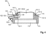
- Fig. 4 shows a schematic view of a holding device introduced into a door holding opening of a laundry care appliance.
- Fig. 4 shows a fastening position of the latching arm 123 of the holding device 123 of a laundry care device 100.
- the deflecting element 127 in particular the cam, must be pressed down with a tool, whereby the latching projection 137 of the latching arm 123 is also pressed down and thus the latching fastening is released and then the holding device 113 can be detached from the laundry care device 100.
- the Figure 5 shows a schematic view of a holding device introduced into a door holding opening of a laundry care appliance.
- a holding device 113 is guided from an inside of the device wall 111 through a door holding opening 139 of the device wall 111, so that an upper section 117 of the holding device 113 extends from the inside of the device wall 111 to an outside 147 of the device wall 111 .
- the upper section 117 has a device receptacle 119 for receiving the door device 109.
- the advantage of the present fastening of the holding device 113 enables an advantageous mechanical fastening of a door device 109 to a front side 107 of the laundry care device 100, and the door holding opening 139 can advantageously be covered, which results in a simplified design of the front side 107 and thus advantageous cleaning options.
- a simple assembly and disassembly of the holding device 113 can be ensured by the deflecting element 127 and an effective locking of the holding device 113 can be checked by an acoustic latching noise from the latching arm 123.
Landscapes
- Engineering & Computer Science (AREA)
- Textile Engineering (AREA)
- Detail Structures Of Washing Machines And Dryers (AREA)
Priority Applications (1)
| Application Number | Priority Date | Filing Date | Title |
|---|---|---|---|
| PL18779353T PL3695044T3 (pl) | 2017-10-12 | 2018-09-26 | Urządzenie do przetwarzania prania z układem mocującym |
Applications Claiming Priority (2)
| Application Number | Priority Date | Filing Date | Title |
|---|---|---|---|
| DE102017218190.7A DE102017218190B3 (de) | 2017-10-12 | 2017-10-12 | Wäschepflegegerät mit einer Haltevorrichtung |
| PCT/EP2018/076112 WO2019072564A1 (de) | 2017-10-12 | 2018-09-26 | Wäschepflegegerät mit einer haltevorrichtung |
Publications (2)
| Publication Number | Publication Date |
|---|---|
| EP3695044A1 EP3695044A1 (de) | 2020-08-19 |
| EP3695044B1 true EP3695044B1 (de) | 2021-11-10 |
Family
ID=63708380
Family Applications (1)
| Application Number | Title | Priority Date | Filing Date |
|---|---|---|---|
| EP18779353.4A Active EP3695044B1 (de) | 2017-10-12 | 2018-09-26 | Wäschepflegegerät mit einer haltevorrichtung |
Country Status (5)
| Country | Link |
|---|---|
| EP (1) | EP3695044B1 (pl) |
| CN (1) | CN111194367B (pl) |
| DE (1) | DE102017218190B3 (pl) |
| PL (1) | PL3695044T3 (pl) |
| WO (1) | WO2019072564A1 (pl) |
Families Citing this family (1)
| Publication number | Priority date | Publication date | Assignee | Title |
|---|---|---|---|---|
| CN120925719A (zh) * | 2024-05-08 | 2025-11-11 | 瀚乐电子机械(南京)有限公司 | 用于家用电器的门锁及用于装配门锁的方法 |
Family Cites Families (6)
| Publication number | Priority date | Publication date | Assignee | Title |
|---|---|---|---|---|
| US2946612A (en) * | 1958-02-24 | 1960-07-26 | Amerock Corp | Self-alining catch |
| ITMI20022369A1 (it) | 2002-11-08 | 2004-05-09 | Elettrotecnica Rold Srl | Dispositivo di bloccaggio del portello di chiusura di una lavabiancheria |
| ITTO20040160U1 (it) * | 2004-12-21 | 2005-03-21 | Bitron Spa | Dispositivo blocca-porta, particolarmente per un apparecchio elettrodomestico |
| DE102005023439A1 (de) * | 2005-05-20 | 2006-11-30 | BSH Bosch und Siemens Hausgeräte GmbH | Türverschlussanbindung |
| CN105088667B (zh) * | 2014-04-22 | 2018-12-07 | 伊利诺斯工具制品有限公司 | 无螺钉安装门锁 |
| CN204959421U (zh) * | 2015-06-30 | 2016-01-13 | 无锡小天鹅股份有限公司 | 用于干衣机的门锁组件和具有其的干衣机 |
-
2017
- 2017-10-12 DE DE102017218190.7A patent/DE102017218190B3/de not_active Expired - Fee Related
-
2018
- 2018-09-26 CN CN201880065704.3A patent/CN111194367B/zh active Active
- 2018-09-26 WO PCT/EP2018/076112 patent/WO2019072564A1/de not_active Ceased
- 2018-09-26 EP EP18779353.4A patent/EP3695044B1/de active Active
- 2018-09-26 PL PL18779353T patent/PL3695044T3/pl unknown
Also Published As
| Publication number | Publication date |
|---|---|
| CN111194367A (zh) | 2020-05-22 |
| WO2019072564A1 (de) | 2019-04-18 |
| DE102017218190B3 (de) | 2019-01-31 |
| PL3695044T3 (pl) | 2022-03-28 |
| CN111194367B (zh) | 2022-04-12 |
| EP3695044A1 (de) | 2020-08-19 |
Similar Documents
| Publication | Publication Date | Title |
|---|---|---|
| EP2281938B1 (de) | Wasserführendes Hausgerät mit einer Schale | |
| DE69824929T2 (de) | Verbindungsvorrichtung für eine IC Karte | |
| EP3472414B1 (de) | Kraftfahrzeug-griffanordnung | |
| DE60316237T2 (de) | Vorrichtung zur Verriegelung der Tür einer Waschmaschine | |
| DE102007009540A1 (de) | Türverriegelung für ein Haushaltsgerät und Verwendung einer solchen in einem Haushaltsgerät | |
| EP2786446A1 (de) | Anschlussklemme mit kniehebelbetätigung | |
| DE102008049864A1 (de) | Steuerkastenanordnung | |
| DE19914370C2 (de) | Waschmaschine mit Transportsicherung | |
| WO2015074941A1 (de) | Scharnier | |
| DE102017218190B3 (de) | Wäschepflegegerät mit einer Haltevorrichtung | |
| WO2011070048A1 (de) | Elektrischer nullkraftsteckverbinder | |
| EP3469663A1 (de) | Steckverbinder | |
| EP4097802B1 (de) | Halterahmen für einen steckverbinder,verfahren, steckverbinder und elektronisches gerät | |
| DE102022103765A1 (de) | Haltering für Vorratsbehälter eines Reinigungschemiesystems und Reinigungschemiesystem | |
| DE20012400U1 (de) | Verriegelungsschieber für Steckerteile von elektrischen Steckverbindungselementen | |
| EP0331220A1 (de) | Türverschluss für Hausgeräte o. dgl. | |
| DE112014007009B4 (de) | Mit einer Tür ausgestattetes Gehäuse | |
| DE202015003360U1 (de) | Abdeckelement für eine Gerätewand eines Hausgeräts und Hausgerät mit einem Abdeckelement | |
| DE102017202678B3 (de) | Wäschepflegegerät mit einem elektromechanischen Bauteil | |
| WO2020069981A1 (de) | Kontakteinsatz, damit gebildete anordnung sowie verfahren zur bereitstellung des kontakteinsatzes | |
| DE102008016773B4 (de) | Vorrichtung zur Positionsüberwachung eines Beschlagbauteils | |
| DE102019206287A1 (de) | Verschließvorrichtung | |
| DE102019007428B3 (de) | Türverschluss für ein elektrisches Haushaltsgerät sowie Verfahren zur Montage eines solchen | |
| DE102022116078A1 (de) | Mechanismus für eine Tür eines elektrischen Haushaltsgeräts | |
| EP2210974B1 (de) | Verschlussanordnung für eine Tür einer Wäschebehandlungsmaschine |
Legal Events
| Date | Code | Title | Description |
|---|---|---|---|
| STAA | Information on the status of an ep patent application or granted ep patent |
Free format text: STATUS: UNKNOWN |
|
| STAA | Information on the status of an ep patent application or granted ep patent |
Free format text: STATUS: THE INTERNATIONAL PUBLICATION HAS BEEN MADE |
|
| PUAI | Public reference made under article 153(3) epc to a published international application that has entered the european phase |
Free format text: ORIGINAL CODE: 0009012 |
|
| STAA | Information on the status of an ep patent application or granted ep patent |
Free format text: STATUS: REQUEST FOR EXAMINATION WAS MADE |
|
| 17P | Request for examination filed |
Effective date: 20200512 |
|
| AK | Designated contracting states |
Kind code of ref document: A1 Designated state(s): AL AT BE BG CH CY CZ DE DK EE ES FI FR GB GR HR HU IE IS IT LI LT LU LV MC MK MT NL NO PL PT RO RS SE SI SK SM TR |
|
| AX | Request for extension of the european patent |
Extension state: BA ME |
|
| DAV | Request for validation of the european patent (deleted) | ||
| DAX | Request for extension of the european patent (deleted) | ||
| GRAP | Despatch of communication of intention to grant a patent |
Free format text: ORIGINAL CODE: EPIDOSNIGR1 |
|
| STAA | Information on the status of an ep patent application or granted ep patent |
Free format text: STATUS: GRANT OF PATENT IS INTENDED |
|
| RIC1 | Information provided on ipc code assigned before grant |
Ipc: D06F 39/12 20060101ALN20210602BHEP Ipc: D06F 39/14 20060101AFI20210602BHEP |
|
| INTG | Intention to grant announced |
Effective date: 20210618 |
|
| GRAS | Grant fee paid |
Free format text: ORIGINAL CODE: EPIDOSNIGR3 |
|
| GRAA | (expected) grant |
Free format text: ORIGINAL CODE: 0009210 |
|
| STAA | Information on the status of an ep patent application or granted ep patent |
Free format text: STATUS: THE PATENT HAS BEEN GRANTED |
|
| AK | Designated contracting states |
Kind code of ref document: B1 Designated state(s): AL AT BE BG CH CY CZ DE DK EE ES FI FR GB GR HR HU IE IS IT LI LT LU LV MC MK MT NL NO PL PT RO RS SE SI SK SM TR |
|
| REG | Reference to a national code |
Ref country code: GB Ref legal event code: FG4D Free format text: NOT ENGLISH |
|
| REG | Reference to a national code |
Ref country code: AT Ref legal event code: REF Ref document number: 1446195 Country of ref document: AT Kind code of ref document: T Effective date: 20211115 Ref country code: CH Ref legal event code: EP |
|
| REG | Reference to a national code |
Ref country code: DE Ref legal event code: R096 Ref document number: 502018007813 Country of ref document: DE |
|
| REG | Reference to a national code |
Ref country code: IE Ref legal event code: FG4D Free format text: LANGUAGE OF EP DOCUMENT: GERMAN |
|
| REG | Reference to a national code |
Ref country code: LT Ref legal event code: MG9D |
|
| REG | Reference to a national code |
Ref country code: NL Ref legal event code: MP Effective date: 20211110 |
|
| PG25 | Lapsed in a contracting state [announced via postgrant information from national office to epo] |
Ref country code: RS Free format text: LAPSE BECAUSE OF FAILURE TO SUBMIT A TRANSLATION OF THE DESCRIPTION OR TO PAY THE FEE WITHIN THE PRESCRIBED TIME-LIMIT Effective date: 20211110 Ref country code: LT Free format text: LAPSE BECAUSE OF FAILURE TO SUBMIT A TRANSLATION OF THE DESCRIPTION OR TO PAY THE FEE WITHIN THE PRESCRIBED TIME-LIMIT Effective date: 20211110 Ref country code: FI Free format text: LAPSE BECAUSE OF FAILURE TO SUBMIT A TRANSLATION OF THE DESCRIPTION OR TO PAY THE FEE WITHIN THE PRESCRIBED TIME-LIMIT Effective date: 20211110 Ref country code: BG Free format text: LAPSE BECAUSE OF FAILURE TO SUBMIT A TRANSLATION OF THE DESCRIPTION OR TO PAY THE FEE WITHIN THE PRESCRIBED TIME-LIMIT Effective date: 20220210 |
|
| PG25 | Lapsed in a contracting state [announced via postgrant information from national office to epo] |
Ref country code: IS Free format text: LAPSE BECAUSE OF FAILURE TO SUBMIT A TRANSLATION OF THE DESCRIPTION OR TO PAY THE FEE WITHIN THE PRESCRIBED TIME-LIMIT Effective date: 20220310 Ref country code: SE Free format text: LAPSE BECAUSE OF FAILURE TO SUBMIT A TRANSLATION OF THE DESCRIPTION OR TO PAY THE FEE WITHIN THE PRESCRIBED TIME-LIMIT Effective date: 20211110 Ref country code: PT Free format text: LAPSE BECAUSE OF FAILURE TO SUBMIT A TRANSLATION OF THE DESCRIPTION OR TO PAY THE FEE WITHIN THE PRESCRIBED TIME-LIMIT Effective date: 20220310 Ref country code: NO Free format text: LAPSE BECAUSE OF FAILURE TO SUBMIT A TRANSLATION OF THE DESCRIPTION OR TO PAY THE FEE WITHIN THE PRESCRIBED TIME-LIMIT Effective date: 20220210 Ref country code: NL Free format text: LAPSE BECAUSE OF FAILURE TO SUBMIT A TRANSLATION OF THE DESCRIPTION OR TO PAY THE FEE WITHIN THE PRESCRIBED TIME-LIMIT Effective date: 20211110 Ref country code: LV Free format text: LAPSE BECAUSE OF FAILURE TO SUBMIT A TRANSLATION OF THE DESCRIPTION OR TO PAY THE FEE WITHIN THE PRESCRIBED TIME-LIMIT Effective date: 20211110 Ref country code: HR Free format text: LAPSE BECAUSE OF FAILURE TO SUBMIT A TRANSLATION OF THE DESCRIPTION OR TO PAY THE FEE WITHIN THE PRESCRIBED TIME-LIMIT Effective date: 20211110 Ref country code: GR Free format text: LAPSE BECAUSE OF FAILURE TO SUBMIT A TRANSLATION OF THE DESCRIPTION OR TO PAY THE FEE WITHIN THE PRESCRIBED TIME-LIMIT Effective date: 20220211 |
|
| PG25 | Lapsed in a contracting state [announced via postgrant information from national office to epo] |
Ref country code: SM Free format text: LAPSE BECAUSE OF FAILURE TO SUBMIT A TRANSLATION OF THE DESCRIPTION OR TO PAY THE FEE WITHIN THE PRESCRIBED TIME-LIMIT Effective date: 20211110 Ref country code: SK Free format text: LAPSE BECAUSE OF FAILURE TO SUBMIT A TRANSLATION OF THE DESCRIPTION OR TO PAY THE FEE WITHIN THE PRESCRIBED TIME-LIMIT Effective date: 20211110 Ref country code: RO Free format text: LAPSE BECAUSE OF FAILURE TO SUBMIT A TRANSLATION OF THE DESCRIPTION OR TO PAY THE FEE WITHIN THE PRESCRIBED TIME-LIMIT Effective date: 20211110 Ref country code: ES Free format text: LAPSE BECAUSE OF FAILURE TO SUBMIT A TRANSLATION OF THE DESCRIPTION OR TO PAY THE FEE WITHIN THE PRESCRIBED TIME-LIMIT Effective date: 20211110 Ref country code: EE Free format text: LAPSE BECAUSE OF FAILURE TO SUBMIT A TRANSLATION OF THE DESCRIPTION OR TO PAY THE FEE WITHIN THE PRESCRIBED TIME-LIMIT Effective date: 20211110 Ref country code: DK Free format text: LAPSE BECAUSE OF FAILURE TO SUBMIT A TRANSLATION OF THE DESCRIPTION OR TO PAY THE FEE WITHIN THE PRESCRIBED TIME-LIMIT Effective date: 20211110 Ref country code: CZ Free format text: LAPSE BECAUSE OF FAILURE TO SUBMIT A TRANSLATION OF THE DESCRIPTION OR TO PAY THE FEE WITHIN THE PRESCRIBED TIME-LIMIT Effective date: 20211110 |
|
| REG | Reference to a national code |
Ref country code: DE Ref legal event code: R097 Ref document number: 502018007813 Country of ref document: DE |
|
| PLBE | No opposition filed within time limit |
Free format text: ORIGINAL CODE: 0009261 |
|
| STAA | Information on the status of an ep patent application or granted ep patent |
Free format text: STATUS: NO OPPOSITION FILED WITHIN TIME LIMIT |
|
| 26N | No opposition filed |
Effective date: 20220811 |
|
| PG25 | Lapsed in a contracting state [announced via postgrant information from national office to epo] |
Ref country code: AL Free format text: LAPSE BECAUSE OF FAILURE TO SUBMIT A TRANSLATION OF THE DESCRIPTION OR TO PAY THE FEE WITHIN THE PRESCRIBED TIME-LIMIT Effective date: 20211110 |
|
| PG25 | Lapsed in a contracting state [announced via postgrant information from national office to epo] |
Ref country code: SI Free format text: LAPSE BECAUSE OF FAILURE TO SUBMIT A TRANSLATION OF THE DESCRIPTION OR TO PAY THE FEE WITHIN THE PRESCRIBED TIME-LIMIT Effective date: 20211110 |
|
| PGFP | Annual fee paid to national office [announced via postgrant information from national office to epo] |
Ref country code: PL Payment date: 20220914 Year of fee payment: 5 |
|
| PG25 | Lapsed in a contracting state [announced via postgrant information from national office to epo] |
Ref country code: MC Free format text: LAPSE BECAUSE OF FAILURE TO SUBMIT A TRANSLATION OF THE DESCRIPTION OR TO PAY THE FEE WITHIN THE PRESCRIBED TIME-LIMIT Effective date: 20211110 |
|
| REG | Reference to a national code |
Ref country code: CH Ref legal event code: PL |
|
| GBPC | Gb: european patent ceased through non-payment of renewal fee |
Effective date: 20220926 |
|
| REG | Reference to a national code |
Ref country code: BE Ref legal event code: MM Effective date: 20220930 |
|
| PG25 | Lapsed in a contracting state [announced via postgrant information from national office to epo] |
Ref country code: IT Free format text: LAPSE BECAUSE OF FAILURE TO SUBMIT A TRANSLATION OF THE DESCRIPTION OR TO PAY THE FEE WITHIN THE PRESCRIBED TIME-LIMIT Effective date: 20211110 |
|
| PG25 | Lapsed in a contracting state [announced via postgrant information from national office to epo] |
Ref country code: LU Free format text: LAPSE BECAUSE OF NON-PAYMENT OF DUE FEES Effective date: 20220926 |
|
| PG25 | Lapsed in a contracting state [announced via postgrant information from national office to epo] |
Ref country code: LI Free format text: LAPSE BECAUSE OF NON-PAYMENT OF DUE FEES Effective date: 20220930 Ref country code: IE Free format text: LAPSE BECAUSE OF NON-PAYMENT OF DUE FEES Effective date: 20220926 Ref country code: FR Free format text: LAPSE BECAUSE OF NON-PAYMENT OF DUE FEES Effective date: 20220930 Ref country code: CH Free format text: LAPSE BECAUSE OF NON-PAYMENT OF DUE FEES Effective date: 20220930 |
|
| PG25 | Lapsed in a contracting state [announced via postgrant information from national office to epo] |
Ref country code: BE Free format text: LAPSE BECAUSE OF NON-PAYMENT OF DUE FEES Effective date: 20220930 |
|
| PG25 | Lapsed in a contracting state [announced via postgrant information from national office to epo] |
Ref country code: GB Free format text: LAPSE BECAUSE OF NON-PAYMENT OF DUE FEES Effective date: 20220926 |
|
| PG25 | Lapsed in a contracting state [announced via postgrant information from national office to epo] |
Ref country code: CY Free format text: LAPSE BECAUSE OF FAILURE TO SUBMIT A TRANSLATION OF THE DESCRIPTION OR TO PAY THE FEE WITHIN THE PRESCRIBED TIME-LIMIT Effective date: 20211110 |
|
| PG25 | Lapsed in a contracting state [announced via postgrant information from national office to epo] |
Ref country code: MK Free format text: LAPSE BECAUSE OF FAILURE TO SUBMIT A TRANSLATION OF THE DESCRIPTION OR TO PAY THE FEE WITHIN THE PRESCRIBED TIME-LIMIT Effective date: 20211110 Ref country code: HU Free format text: LAPSE BECAUSE OF FAILURE TO SUBMIT A TRANSLATION OF THE DESCRIPTION OR TO PAY THE FEE WITHIN THE PRESCRIBED TIME-LIMIT; INVALID AB INITIO Effective date: 20180926 |
|
| PG25 | Lapsed in a contracting state [announced via postgrant information from national office to epo] |
Ref country code: MT Free format text: LAPSE BECAUSE OF FAILURE TO SUBMIT A TRANSLATION OF THE DESCRIPTION OR TO PAY THE FEE WITHIN THE PRESCRIBED TIME-LIMIT Effective date: 20211110 |
|
| REG | Reference to a national code |
Ref country code: AT Ref legal event code: MM01 Ref document number: 1446195 Country of ref document: AT Kind code of ref document: T Effective date: 20230926 |
|
| PG25 | Lapsed in a contracting state [announced via postgrant information from national office to epo] |
Ref country code: PL Free format text: LAPSE BECAUSE OF NON-PAYMENT OF DUE FEES Effective date: 20230926 |
|
| PG25 | Lapsed in a contracting state [announced via postgrant information from national office to epo] |
Ref country code: AT Free format text: LAPSE BECAUSE OF NON-PAYMENT OF DUE FEES Effective date: 20230926 |
|
| PG25 | Lapsed in a contracting state [announced via postgrant information from national office to epo] |
Ref country code: PL Free format text: LAPSE BECAUSE OF NON-PAYMENT OF DUE FEES Effective date: 20230926 Ref country code: AT Free format text: LAPSE BECAUSE OF NON-PAYMENT OF DUE FEES Effective date: 20230926 |
|
| PGFP | Annual fee paid to national office [announced via postgrant information from national office to epo] |
Ref country code: DE Payment date: 20250930 Year of fee payment: 8 |
|
| PGFP | Annual fee paid to national office [announced via postgrant information from national office to epo] |
Ref country code: TR Payment date: 20250918 Year of fee payment: 8 |
|
| PGFP | Annual fee paid to national office [announced via postgrant information from national office to epo] |
Ref country code: AT Payment date: 20260410 Year of fee payment: 5 |