EP3694741B1 - Zugtraktionssystem - Google Patents
Zugtraktionssystem Download PDFInfo
- Publication number
- EP3694741B1 EP3694741B1 EP18867057.4A EP18867057A EP3694741B1 EP 3694741 B1 EP3694741 B1 EP 3694741B1 EP 18867057 A EP18867057 A EP 18867057A EP 3694741 B1 EP3694741 B1 EP 3694741B1
- Authority
- EP
- European Patent Office
- Prior art keywords
- switches
- electric power
- train
- traction system
- converters
- Prior art date
- Legal status (The legal status is an assumption and is not a legal conclusion. Google has not performed a legal analysis and makes no representation as to the accuracy of the status listed.)
- Active
Links
Images


Classifications
-
- B—PERFORMING OPERATIONS; TRANSPORTING
- B60—VEHICLES IN GENERAL
- B60L—PROPULSION OF ELECTRICALLY-PROPELLED VEHICLES; SUPPLYING ELECTRIC POWER FOR AUXILIARY EQUIPMENT OF ELECTRICALLY-PROPELLED VEHICLES; ELECTRODYNAMIC BRAKE SYSTEMS FOR VEHICLES IN GENERAL; MAGNETIC SUSPENSION OR LEVITATION FOR VEHICLES; MONITORING OPERATING VARIABLES OF ELECTRICALLY-PROPELLED VEHICLES; ELECTRIC SAFETY DEVICES FOR ELECTRICALLY-PROPELLED VEHICLES
- B60L15/00—Methods, circuits, or devices for controlling the traction-motor speed of electrically-propelled vehicles
- B60L15/20—Methods, circuits, or devices for controlling the traction-motor speed of electrically-propelled vehicles for control of the vehicle or its driving motor to achieve a desired performance, e.g. speed, torque, programmed variation of speed
- B60L15/22—Methods, circuits, or devices for controlling the traction-motor speed of electrically-propelled vehicles for control of the vehicle or its driving motor to achieve a desired performance, e.g. speed, torque, programmed variation of speed with sequential operation of interdependent switches, e.g. relays, contactors or program drum
-
- B—PERFORMING OPERATIONS; TRANSPORTING
- B60—VEHICLES IN GENERAL
- B60L—PROPULSION OF ELECTRICALLY-PROPELLED VEHICLES; SUPPLYING ELECTRIC POWER FOR AUXILIARY EQUIPMENT OF ELECTRICALLY-PROPELLED VEHICLES; ELECTRODYNAMIC BRAKE SYSTEMS FOR VEHICLES IN GENERAL; MAGNETIC SUSPENSION OR LEVITATION FOR VEHICLES; MONITORING OPERATING VARIABLES OF ELECTRICALLY-PROPELLED VEHICLES; ELECTRIC SAFETY DEVICES FOR ELECTRICALLY-PROPELLED VEHICLES
- B60L15/00—Methods, circuits, or devices for controlling the traction-motor speed of electrically-propelled vehicles
- B60L15/32—Control or regulation of multiple-unit electrically-propelled vehicles
-
- B—PERFORMING OPERATIONS; TRANSPORTING
- B60—VEHICLES IN GENERAL
- B60L—PROPULSION OF ELECTRICALLY-PROPELLED VEHICLES; SUPPLYING ELECTRIC POWER FOR AUXILIARY EQUIPMENT OF ELECTRICALLY-PROPELLED VEHICLES; ELECTRODYNAMIC BRAKE SYSTEMS FOR VEHICLES IN GENERAL; MAGNETIC SUSPENSION OR LEVITATION FOR VEHICLES; MONITORING OPERATING VARIABLES OF ELECTRICALLY-PROPELLED VEHICLES; ELECTRIC SAFETY DEVICES FOR ELECTRICALLY-PROPELLED VEHICLES
- B60L9/00—Electric propulsion with power supply external to the vehicle
- B60L9/005—Interference suppression
-
- B—PERFORMING OPERATIONS; TRANSPORTING
- B60—VEHICLES IN GENERAL
- B60L—PROPULSION OF ELECTRICALLY-PROPELLED VEHICLES; SUPPLYING ELECTRIC POWER FOR AUXILIARY EQUIPMENT OF ELECTRICALLY-PROPELLED VEHICLES; ELECTRODYNAMIC BRAKE SYSTEMS FOR VEHICLES IN GENERAL; MAGNETIC SUSPENSION OR LEVITATION FOR VEHICLES; MONITORING OPERATING VARIABLES OF ELECTRICALLY-PROPELLED VEHICLES; ELECTRIC SAFETY DEVICES FOR ELECTRICALLY-PROPELLED VEHICLES
- B60L2200/00—Type of vehicles
- B60L2200/26—Rail vehicles
-
- B—PERFORMING OPERATIONS; TRANSPORTING
- B60—VEHICLES IN GENERAL
- B60L—PROPULSION OF ELECTRICALLY-PROPELLED VEHICLES; SUPPLYING ELECTRIC POWER FOR AUXILIARY EQUIPMENT OF ELECTRICALLY-PROPELLED VEHICLES; ELECTRODYNAMIC BRAKE SYSTEMS FOR VEHICLES IN GENERAL; MAGNETIC SUSPENSION OR LEVITATION FOR VEHICLES; MONITORING OPERATING VARIABLES OF ELECTRICALLY-PROPELLED VEHICLES; ELECTRIC SAFETY DEVICES FOR ELECTRICALLY-PROPELLED VEHICLES
- B60L2210/00—Converter types
- B60L2210/20—AC to AC converters
-
- B—PERFORMING OPERATIONS; TRANSPORTING
- B60—VEHICLES IN GENERAL
- B60L—PROPULSION OF ELECTRICALLY-PROPELLED VEHICLES; SUPPLYING ELECTRIC POWER FOR AUXILIARY EQUIPMENT OF ELECTRICALLY-PROPELLED VEHICLES; ELECTRODYNAMIC BRAKE SYSTEMS FOR VEHICLES IN GENERAL; MAGNETIC SUSPENSION OR LEVITATION FOR VEHICLES; MONITORING OPERATING VARIABLES OF ELECTRICALLY-PROPELLED VEHICLES; ELECTRIC SAFETY DEVICES FOR ELECTRICALLY-PROPELLED VEHICLES
- B60L2210/00—Converter types
- B60L2210/30—AC to DC converters
-
- B—PERFORMING OPERATIONS; TRANSPORTING
- B60—VEHICLES IN GENERAL
- B60L—PROPULSION OF ELECTRICALLY-PROPELLED VEHICLES; SUPPLYING ELECTRIC POWER FOR AUXILIARY EQUIPMENT OF ELECTRICALLY-PROPELLED VEHICLES; ELECTRODYNAMIC BRAKE SYSTEMS FOR VEHICLES IN GENERAL; MAGNETIC SUSPENSION OR LEVITATION FOR VEHICLES; MONITORING OPERATING VARIABLES OF ELECTRICALLY-PROPELLED VEHICLES; ELECTRIC SAFETY DEVICES FOR ELECTRICALLY-PROPELLED VEHICLES
- B60L2210/00—Converter types
- B60L2210/40—DC to AC converters
-
- B—PERFORMING OPERATIONS; TRANSPORTING
- B60—VEHICLES IN GENERAL
- B60L—PROPULSION OF ELECTRICALLY-PROPELLED VEHICLES; SUPPLYING ELECTRIC POWER FOR AUXILIARY EQUIPMENT OF ELECTRICALLY-PROPELLED VEHICLES; ELECTRODYNAMIC BRAKE SYSTEMS FOR VEHICLES IN GENERAL; MAGNETIC SUSPENSION OR LEVITATION FOR VEHICLES; MONITORING OPERATING VARIABLES OF ELECTRICALLY-PROPELLED VEHICLES; ELECTRIC SAFETY DEVICES FOR ELECTRICALLY-PROPELLED VEHICLES
- B60L2240/00—Control parameters of input or output; Target parameters
- B60L2240/80—Time limits
-
- B—PERFORMING OPERATIONS; TRANSPORTING
- B60—VEHICLES IN GENERAL
- B60L—PROPULSION OF ELECTRICALLY-PROPELLED VEHICLES; SUPPLYING ELECTRIC POWER FOR AUXILIARY EQUIPMENT OF ELECTRICALLY-PROPELLED VEHICLES; ELECTRODYNAMIC BRAKE SYSTEMS FOR VEHICLES IN GENERAL; MAGNETIC SUSPENSION OR LEVITATION FOR VEHICLES; MONITORING OPERATING VARIABLES OF ELECTRICALLY-PROPELLED VEHICLES; ELECTRIC SAFETY DEVICES FOR ELECTRICALLY-PROPELLED VEHICLES
- B60L2270/00—Problem solutions or means not otherwise provided for
- B60L2270/10—Emission reduction
- B60L2270/14—Emission reduction of noise
- B60L2270/147—Emission reduction of noise electro magnetic [EMI]
-
- B—PERFORMING OPERATIONS; TRANSPORTING
- B60—VEHICLES IN GENERAL
- B60L—PROPULSION OF ELECTRICALLY-PROPELLED VEHICLES; SUPPLYING ELECTRIC POWER FOR AUXILIARY EQUIPMENT OF ELECTRICALLY-PROPELLED VEHICLES; ELECTRODYNAMIC BRAKE SYSTEMS FOR VEHICLES IN GENERAL; MAGNETIC SUSPENSION OR LEVITATION FOR VEHICLES; MONITORING OPERATING VARIABLES OF ELECTRICALLY-PROPELLED VEHICLES; ELECTRIC SAFETY DEVICES FOR ELECTRICALLY-PROPELLED VEHICLES
- B60L2270/00—Problem solutions or means not otherwise provided for
- B60L2270/20—Inrush current reduction, i.e. avoiding high currents when connecting the battery
-
- Y—GENERAL TAGGING OF NEW TECHNOLOGICAL DEVELOPMENTS; GENERAL TAGGING OF CROSS-SECTIONAL TECHNOLOGIES SPANNING OVER SEVERAL SECTIONS OF THE IPC; TECHNICAL SUBJECTS COVERED BY FORMER USPC CROSS-REFERENCE ART COLLECTIONS [XRACs] AND DIGESTS
- Y02—TECHNOLOGIES OR APPLICATIONS FOR MITIGATION OR ADAPTATION AGAINST CLIMATE CHANGE
- Y02T—CLIMATE CHANGE MITIGATION TECHNOLOGIES RELATED TO TRANSPORTATION
- Y02T10/00—Road transport of goods or passengers
- Y02T10/60—Other road transportation technologies with climate change mitigation effect
- Y02T10/64—Electric machine technologies in electromobility
-
- Y—GENERAL TAGGING OF NEW TECHNOLOGICAL DEVELOPMENTS; GENERAL TAGGING OF CROSS-SECTIONAL TECHNOLOGIES SPANNING OVER SEVERAL SECTIONS OF THE IPC; TECHNICAL SUBJECTS COVERED BY FORMER USPC CROSS-REFERENCE ART COLLECTIONS [XRACs] AND DIGESTS
- Y02—TECHNOLOGIES OR APPLICATIONS FOR MITIGATION OR ADAPTATION AGAINST CLIMATE CHANGE
- Y02T—CLIMATE CHANGE MITIGATION TECHNOLOGIES RELATED TO TRANSPORTATION
- Y02T10/00—Road transport of goods or passengers
- Y02T10/60—Other road transportation technologies with climate change mitigation effect
- Y02T10/72—Electric energy management in electromobility
Definitions
- the present disclosure relates to a traction system for a train.
- railway lines often have electrical trackside safety and communication equipment used to transmit information (e.g. speed restrictions, stop locations etc.) to traffic on the lines in order to prevent unsafe train operation and thereby avoid accidents.
- information e.g. speed restrictions, stop locations etc.
- Electric-powered trains using such lines typically have a traction system which converts electric power provided from an overhead wire to suitable AC power for one or more traction motors mounted on the trains.
- the traction systems may include AC/DC converters.
- PWM converters are in widespread use, the PWM converter comprising bridge-connected diodes, with each diode having a self-extinction type switching element (e.g. an IGBT) connected in inverse-parallel thereto.
- GB A 2527881 and GB A 2537732 propose addressing this problem by adopting plural AC/DC converters which have the same PWM switching frequency but which are operated so that the PWM carrier waves (i.e. pulse signals) of the respective converters are phase shifted from each other in order to cancel out each other's second order harmonic noise (i.e. noise at twice the frequency of the pulse signals), and hence reduce the noise signal flowing into the rails.
- US 5642020 proposes an electric vehicle control device wherein electric motors are driven by PWM converters and inverters.
- Document JPH0583803 relates to an electric vehicle control apparatus for controlling an electric vehicle driving motor using a variable voltage-frequency inverter.
- the traction system typically further includes transformer equipment for stepping down the electric voltage level from the high voltage of the overhead wire, the AC/DC converters operating on the stepped down voltage to convert it to DC, which is then further manipulated to provide AC power for the motors.
- transformer equipment for stepping down the electric voltage level from the high voltage of the overhead wire
- the AC/DC converters operating on the stepped down voltage to convert it to DC, which is then further manipulated to provide AC power for the motors.
- an inrush current flows into the transformer equipment from the power source, resulting in another noise current.
- the individual noise currents can reinforce each other to such an extent that operation of the trackside safety and communication equipment can be compromised.
- the present invention aims to address such problems.
- an aim is to reduce noise created by the traction system and thereby reduce the risk of compromising the operation of trackside safety and communication equipment.
- the present invention aims to address the technical problem of minimising the noise current caused by interference of the inrush currents supplied from the power source to the plurality of transformers via the overhead line, and suppressing higher-order harmonics in the harmonic noise generated by the AC/DC converters via phase shifting.
- the present invention provides a traction system for a train according to claim 1.
- the present invention provides a train having the traction system of the first embodiment.
- the present invention provides a train set including first and second coupled trains, each according to the second embodiment, wherein the controllers of the coupled trains are further configured such that the start of the sequential closing of the first switches of the second train occurs a further predetermined time interval after the completion of the sequential closing of the first switches of the first train.
- the controllers of the coupled trains may be further configured such that the power conversion using pulse width modulation by the AC/DC converters of the first train is started before completion of the sequential closing of the first switches of the second train.
- the present invention provides respective uses of the traction system, train and train set of the first to third embodiments and respective methods of operating the traction system, train and train set of the first to third embodiments. For example, a method of operating a traction system for a train according to claim 12 is provided.
- the system may have three or more of the converter units.
- at least three AC/DC converters are needed to use phase shifting to cancel out second order harmonic noise.
- the system may have two or more of the transformers.
- one transformer may provide stepped down AC electric power to more than one converter unit.
- the first predetermined time interval may be selected such that the inrush current provoked by the closing of a previous first switch peaks before a next first switch closes.
- the traction system may have: plural second switches which are closable to respectively connect the AC/DC converters to low voltage sides of the transformers.
- the controller may then be further configured to control: the timing of the closing of the second switches such that each second switch closes a second predetermined time interval after the first switch which connects the high voltage sides of the respective transformer to the overhead wire has closed; and the timing of the start of power conversion using pulse width modulation by each of the AC/DC converters such that the starts are simultaneous and after the first and the second switches have closed.
- the traction system may have: one or more pantographs for obtaining the AC electric power from the overhead wire; a power line which connects the overhead wire sides of the first switches; and one or more third switches which are closable to respectively connect the one or more pantographs to the power line.
- the controller may then be further configured to control the timing of the closing of the one or more third switches such that the one or more third switches close before the start of the sequential closing of the first switches.
- Each converter unit further includes an inverter for converting the DC electric power provided by the AC/DC convertor to multiphase AC electric power.
- Each converter unit may then further include a smoothing capacitor between the AC/DC convertor and the inverter.
- the traction system may further have plural traction motors driven by the multiphase AC electric power provided by the converter units.
- Figure 1 shows schematically the structure of a first traction system.
- the system is located in a train made up of nine cars (Cars 1-9).
- Cars 2, 3, 5, 7 and 8 each have a traction converter (CNV) unit 1 and a traction motor 4 powered by the CNV unit to drive the train.
- Cars 1, 4, 6 and 9 are without CNV units and traction motors, but Cars 1, 4 and 9 each have transformer equipment 2, and Cars 1 and 9 also each have a pantograph 3 for collecting high voltage AC electric power from an overhead wire.
- the high voltage sides of the transformer equipment are connected by a power line 8 which extends from Car 1 to Car 9.
- the AC power collected by the pantographs 3 is provided to the transformer equipment 2 and then, as stepped down AC power, to the CNV units.
- the CNV units 1 convert this stepped down single-phase AC power to three-phase AC power, and provide the three-phase power to the motors 4.
- the flow of power through the system is controlled by first breaker switches 6, second breaker switches 7 and third breaker switches 5.
- the third breaker switches 5 are closable to respectively connect the pantographs to the power line 8.
- the first breaker switches 6 are closable to connect the high voltage sides of the transformer equipment 2 to the overhead wire power line 8 and thence the overhead wire.
- the second breaker switches 7 are closable to connect the CNV units 1 to the low voltage sides of the transformer equipment 2.
- each car having a pantograph 3 has a third breaker switch 5
- each car having transformer equipment 2 has a first breaker switch 6, and each car having a CNV unit 1 has a second breaker switch 7.
- FIG. 2 shows schematically more detail of the structure of the CNV unit 1.
- the CNV unit 1 comprises a PWM-operated AC/DC converter 101 which converts the stepped down AC power to DC power, an inverter 103 which converts the DC power to multiphase AC power with a variable voltage and frequency and provides the AC power to a traction motor 4, and a smoothing capacitor or condenser 102 connected between the AC/DC converter and the inverter to smooth DC voltage.
- Figure 3 shows schematically how the PWM-operation of the CNV units 1 can be phase shifted to cancel out second order harmonic noise.
- the following phase differences can be set for the PWM pulse signals of the five AC/DC converters 101 of the CNV units: Car 2: 144°, Car 3: 108°, Car 5: 72°, Car 7: 36°, Car 8: 0°.
- These phase differences correspond to a 36° car-to-car shift, and can be set relative to the zero-crossing point of the input stepped down AC power (which has, typically, a 50 Hz frequency) as this is a reference available to all the CNV units. Further details can be found in GB A 2527881 and GB A 2537732 .
- Figure 4 shows schematically functions of a control unit 9 for controlling the traction system.
- the control unit 9 ca be mounted on any car of the train.
- Command signals (open/close) for the first 6 and third 5 breaker switches can be sent directly to the respective switch from the control unit.
- Command signals for the second breaker switch 7 can also be sent to the respective switches from the control unit, but typically via the respective CNV unit 1.
- the control unit 9 collects switch status directory information (open/close) directly from the switches or via communication with the CNV units.
- the control unit also sends command signals to the CNV units 1 to start/stop power conversion, and collects operation status information (operating/non-operating) from the CNV units by communication therewith.
- FIG. 5 shows a comparative example first starting sequence for the transformers 2 and the CNV units 1 of the system of Figure 1 , as controlled by the control unit 9.
- First one of the pantograph 3 mounted on Cars 1 and 9 is deployed and made ready to collect electrical power from the overhead wire (stand-by condition).
- its third breaker switch 5 is closed (t0).
- a predetermined time e.g. 1 sec
- the three first breakers switches 6 mounted in Cars 1, 4, and 9 are closed (t1). This causes an inrush current flow into the three transformers 2, and a corresponding noise current is created.
- Another predetermined time e.g.
- This first starting sequence makes it possible to reduce harmonic noise from the pulse signals immediately the AC/DC converters 101 commence their switching operation because all the multiple CNV units are made ready to start at the same time.
- the three transformers 2 are connected to the AC power source at the same time (t1) and provoke simultaneous inrush currents.
- t1 the AC power source
- both the DC and AC components of the combined noise currents created by the inrush currents superimpose on each other.
- the peak noise current can be three times higher than that created by the connection of a single transformer.
- Figure 7 shows a comparative example second starting sequence for the transformers 2 and the CNV units 1 of the system of Figure 1 .
- This sequence can avoid some of the worst effects of the superposition of the noise currents created by the inrush currents of the transformers 2.
- one of the pantographs 3 mounted on Cars 1 and 9 is deployed and made ready to collect electrical power from the overhead wire (stand-by condition).
- its third breaker switch 5 is closed (t0).
- a predetermined time e.g. 1 sec
- the first breaker switch 6 mounted in Car 1 is closed (t1). This causes an inrush current flow into its transformer 2, and a corresponding noise current is created.
- Another predetermined time (e.g. 1 sec) after the closure of the first breaker switch, the second breaker switches 7 in Cars 2 and 3 for the respective CNV units 1 of those cars are closed (t2).
- the second breaker switches of Cars 2 and 3 are closed, DC current flows into the capacitors 102 of their CNV units through the diode elements of the AC/DC converters 101, and the capacitors charge up and their voltage increases.
- Yet another predetermined time e.g. 1 sec) after the closures of the second breaker switches of Cars 2 and 3, the AC/DC converters 101 of Cars 2 and 3 start their switching operations with the above-mentioned (36°) phase shifts in their PWM pulse signals (t3).
- Another predetermined time (e.g. 2 sec) after the first breaker switch 6 of Car 1 is closed, the first breaker switch 6 mounted in Car 9 is closed (t3). This causes an inrush current flow into its transformer 2, and a corresponding noise current is created.
- a predetermined time (e.g. 1 sec) after the closure of the first breaker switch, the second breaker switches 7 in Cars 7 and 8 for the respective CNV units 1 of those cars are closed (t4).
- the second breaker switches of Cars 7 and 8 are closed, DC current flows into the capacitors 102 through the diode elements of the AC/DC converters 101, and the capacitors charge up and their voltage increases.
- Yet another predetermined time (e.g. 1 sec) after the closures of the second breaker switches of Cars 7 and 8, the AC/DC converters 101 of Cars 7 and 8 start their switching operations with the phase shifts in their PWM pulse signals (t5).
- the transformers 2 can be connected to the AC power source at different times with predetermined time intervals therebetween. Hence, it is possible to reduce the amount of overlap of the noise currents created by their respective inrush currents. In this way the peak level of the combined noise currents can be reduced.
- the timings of the start-ups of the AC/DC converters 101 vary between the converters (t3, t5, t7). Hence, the phase difference harmonic noise reduction does not work well during the period from t2 to t7 when only some of the AC/DC converters 101 are operating. In particular, when only the AC/DC converters 101 of Cars 2 and 3 are operating, the second order harmonic noise is greatly increased.
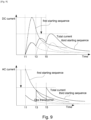
- Figure 8 shows an example third starting sequence for the transformers 2 and the CNV units 1 of the system of Figure 1 .
- This sequence can avoid some of the worst effects of the superposition of the noise currents created by the inrush currents of the transformers 2, and also can reduce second order harmonic noise from the CNV units 1.
- one of the pantographs 3 mounted on Cars 1 and 9 is deployed and made ready to collect electrical power from the overhead wire (stand-by condition).
- its third breaker switch 5 is closed (t0).
- a predetermined time e.g. 1 sec
- the first breaker switch 6 mounted in Car 1 is closed (t1).
- Another predetermined time (e.g. 2 sec) after the first breaker switch 6 of Car 1 is closed, the first breaker switch 6 mounted in Car 9 is closed (t3). This causes an inrush current flow into its transformer 2, and a corresponding noise current is created.
- a predetermined time (e.g. 1 sec) after the closure of the first breaker switch, the second breaker switches 7 in Cars 7 and 8 for the respective CNV units 1 of those cars are closed (t4).
- the second breaker switches of Cars 7 and 8 are closed, DC current flows into the capacitors 102 through the diode elements of the AC/DC converters 101, and the capacitors charge up and their voltage increases.
- the start of switching operations of the AC/DC converters 101 of Cars 7 and 8 is delayed.
- Yet another predetermined time (e.g. 2 sec) after the first breaker switch 6 of Car 9 is closed, the first breaker switch 6 mounted in Car 4 is closed (t5). This causes an inrush current flow into its transformer 2, and a corresponding noise current is created.
- a predetermined time (e.g. 1 sec) after the closure of the first breaker switch, the second breaker switch 7 in Car 5 is closed (t6). When the second breaker switch of Car 5 is closed, DC current flows into the capacitor 102 of its CNV unit through the diode elements of the AC/DC converter 101, and the capacitor charges up and its voltage increases.
- a further predetermined time e.g. 2 sec
- the control unit commands the AC/DC converters 101 of all of Cars 2, 3, 5, 7 and 8 simultaneously to start their phase-shifted switching operations (t7).
- t7 phase-shifted switching operations
- the transformers 2 are connected to the AC power source in a sequential order with a two second time interval between closures of the first breaker switches 6.
- the time interval between first breaker switch closures can be set to be longer than the time period over which the level of DC and AC noise current reduces by a suitable amount.
- the time interval can be such that the inrush current, and hence the noise current, provoked by the previous switch closure has peaked before the next switch closure occurs.
- Figure 10 shows schematically the structure of a second traction system.
- the system is located in a train made up of five cars (Cars 1-5).
- Cars 2, 3 and 4 each have a traction converter (CNV) unit 1 and a traction motor 4 powered by the CNV unit to drive the train.
- Cars 1 and 9 are without CNV units and traction motors, but each have transformer equipment 2 and a pantograph 3 for collecting high voltage AC electric power from an overhead wire. Again, the high voltage sides of the transformer equipment are connected by a power line 8 which extends from Car 1 to Car 5.
- CNV traction converter
- Figure 11 shows schematically how the phase shifted PWM-operation of the CNV units 1 cancel out second order harmonic noise.
- the following phase differences corresponding to a 60° car-to-car shift, can be set for the PWM pulse signals of the three AC/DC converters 101 of the CNV units: Car 2: 120°, Car 3: 60°, Car 4: 0°.
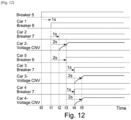
- FIG 12 shows a comparative example fourth starting sequence for the transformers 2 and the CNV units 1 of the system of Figure 10 as controlled by its control unit 9.
- this starting up sequence it is possible to avoid the overlapping of noise current from the transformers created by their respective inrush currents.
- the transformers 2 are connected to the AC power source at different times (i.e. t1 and t3).
- the starting up timing (t3) of the AC/DC converter 101 mounted on Car 2 is earlier than the starting up timings (t5) of the AC/DC converters 101 mounted on Cars 3 and 4.
- the harmonic noise from the AC/DC converter (101) of Car 2 cannot be cancelled.
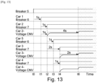
- Figure 13 shows a fifth starting sequence for the transformers 2 and the CNV units 1 of the system of Figure 10 .
- this starting up sequence it is possible to avoid the overlapping of noise current from the transformers 2, and to reduce harmonic noise from the CNV units 1.
- one of the pantographs 3 mounted on Cars 1 and 5 is deployed and made ready to collect electrical power from the overhead wire (stand-by condition).
- its third breaker switch 5 is closed (t0).
- a predetermined time e.g. 1 sec
- the first breaker switch 6 mounted in Car 1 is closed (t1). This causes an inrush current flow into its transformer 2, and a corresponding noise current is created.
- Another predetermined time e.g. 1 sec) after the closure of the first breaker switch, the second breaker switch 7 in Car 2 for the CNV unit 1 of that car is closed (t2).
- Another predetermined time (e.g. 2 sec) after the first breaker switch 6 of Car 1 is closed, the first breaker switch 6 mounted in Car 5 is closed (t3). This causes an inrush current flow into its transformer 2, and a corresponding noise current is created.
- a predetermined time (e.g. 1 sec) after the closure of the first breaker switch, the second breaker switches 7 in Cars 3 and 4 for the respective CNV units 1 of those cars are closed (t4).
- the second breaker switches of Cars 3 and 4 are closed, DC current flows into the capacitors 102 through the diode elements of the AC/DC converters 101, and the capacitors charge up and their voltage increases.
- the transformers 2 are connected with the AC power source at different times with a predetermined time interval therebetween.
- the fifth starting sequence it is possible with the fifth starting sequence to reduce the amount of overlap of the noise currents created by their respective inrush currents.
- the peak level of the combined noise currents can be reduced.
- the peak levels of both the DC and AC components of the combined noise currents created by the inrush currents can be decreased relative to the DC and AC components of the combined noise currents that would occur under the fourth starting sequence.
- a further predetermined time e.g. 2 sec
- the control unit commands the AC/DC converters 101 of all of Cars 2, 3 and 4 to start simultaneously their phase-shifted switching operations (t6). In this way it is possible to reduce second (and fourth and eighth) order harmonic noise from the pulse signals even when the AC/DC converters 101 are starting up.
- FIG 15 shows schematically the structures of two traction systems. Each system is located in a respective train (T1 and T2) made up of five cars (Cars 1-5). The two trains are mechanically coupled to form a train set, but the each traction system is electrically independent from the other. The two traction systems are identical to each and are the same as the traction system described above in relation to Figure 10 .
- Figure 16 shows schematically how the phase shifted PWM-operation of the CNV units 1 cancel out second order harmonic noise.
- the following phase differences corresponding to a 60° car-to-car shift, can be set for the PWM pulse signals of the three AC/DC converters 101 of the CNV units of T1: Car 2: 120°, Car 3: 60°, Car 4: 0°.
- the following phase differences, corresponding to a 60° car-to-car shift can be set for the PWM pulse signals of the three AC/DC converters 101 of the CNV units of T2: Car 2: 150°, Car 3: 90°, Car 4: 30°.
- the traction system of each train is thus set up to cancel out second order harmonic noise.
- FIG 17 shows a possible sixth starting sequence for the transformers 2 and the CNV units 1 of the systems of Figure 15 as controlled by their respective control units 9.
- this starting up sequence it is possible to avoid overlapping of noise current from the transformers created by their respective inrush currents.
- the transformers are connected to the AC power source at different times (t1, t3, t5 and t7).
- the starting up timing (t3) of the AC/DC converter 101 mounted on T1 Car 2 is earlier than the starting up timings (t5) of the AC/DC converters 101 mounted on T1 Cars 3 and 4.
- the starting up timing (t7) of the AC/DC converter 101 mounted on T2 Car 2 is earlier than the starting up timings (t9) of the AC/DC converters 101 mounted on T2 Cars 3 and 4.
- the harmonic noise from the AC/DC converter (101) of T1 Car 2 cannot be cancelled
- the harmonic noise from the AC/DC converter (101) of T2 Car 2 cannot be cancelled.
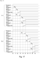
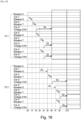
- Figure 18 shows a possible seventh starting sequence for the transformers 2 and the CNV units 1 of the systems of Figure 15 .
- this starting up sequence it is possible to avoid the overlapping of noise current from the transformers 2, and to reduce harmonic noise from the CNV units 1.
- one of the pantographs 3 mounted on T1 Cars 1 and 5 is deployed and one of the pantographs 3 mounted on T2 Cars 1 and 5 is deployed, and both are made ready to collect electrical power from the overhead wire (stand-by condition).
- their third breaker switches 5 are closed (t0).
- a predetermined time e.g. 1 sec
- the first breaker switch 6 mounted in T1 Car 1 is closed (t1). This causes an inrush current flow into its transformer 2, and a corresponding noise current is created.
- a predetermined time e.g. 1 sec
- the second breaker switch 7 in T1 Car 2 for the CNV unit 1 of that car is closed (t2).
- DC current flows into the capacitor 102 of its CNV unit through the diode elements of the AC/DC converter 101, and the capacitor charges up and its voltage increases.
- the start of switching operations of the AC/DC converter 101 of T1 Car 2 is delayed.
- Another predetermined time (e.g. 2 sec) after the first breaker switch 6 of T1 Car 1 is closed, the first breaker switch 6 mounted in T1 Car 5 is closed (t3). This causes an inrush current flow into its transformer 2, and a corresponding noise current is created.
- a predetermined time (e.g. 1 sec) after the closure of the first breaker switch, the second breaker switches 7 in T1 Cars 3 and 4 for the respective CNV units 1 of those cars are closed (t4).
- the second breaker switches of T1 Cars 3 and 4 are closed, DC current flows into the capacitors 102 through the diode elements of the AC/DC converters 101, and the capacitors charge up and their voltage increases.
- a further predetermined time e.g. 2 sec
- the T1 control unit 1 commands the AC/DC converters 101 of all of T1 Cars 2, 3 and 4 to start simultaneously their phase-shifted switching operations (t6). In this way it is possible to reduce second (and fourth and eighth) order harmonic noise from the pulse signals for T1 even when the AC/DC converters 101 are starting up.
- a predetermined time e.g. 2 sec
- the first breaker switch 6 mounted in T2 Car 1 is closed (t5). This causes an inrush current flow into its transformer 2, and a corresponding noise current is created.
- Another predetermined time e.g. 1 sec
- the second breaker switch 7 in T2 Car 2 for the CNV unit 1 of that car is closed (t6).
- the second breaker switch of T2 Car 2 is closed, DC current flows into the capacitor 102 of its CNV unit through the diode elements of the AC/DC converter 101, and the capacitor charges up and its voltage increases. However, even though the capacitor is ready, the start of switching operations of the AC/DC converter 101 of T2 Car 2 is delayed.
- Another predetermined time (e.g. 2 sec) after the first breaker switch 6 of T2 Car 1 is closed, the first breaker switch 6 mounted in T2 Car 5 is closed (t7). This causes an inrush current flow into its transformer 2, and a corresponding noise current is created.
- a predetermined time (e.g. 1 sec) after the closure of the first breaker switch, the second breaker switches 7 in T2 Cars 3 and 4 for the respective CNV units 1 of those cars are closed (t8).
- the second breaker switches of T2 Cars 3 and 4 are closed, DC current flows into the capacitors 102 through the diode elements of the AC/DC converters 101, and the capacitors charge up and their voltage increases.
- a further predetermined time e.g. 2 sec
- the T2 control unit 1 commands the AC/DC converters 101 of all of T2 Cars 2, 3 and 4 to start simultaneously their phase-shifted switching operations (t6). In this way it is also possible to reduce second (and fourth and eighth) order harmonic noise from the pulse signals for T2 even when the AC/DC converters 101 are starting up.
- the T1 and T2 transformers 2 are connected with the AC power source at different times with a predetermined time interval therebetween. Hence, it is possible with the seventh starting sequence to reduce the amount of overlap of the noise currents created by their respective inrush currents. In this way the peak level of the combined noise currents can be reduced.
- Another advantage of the seventh starting sequence is that it is possible to shorten the time from sequence initiation to motor output. This is because the CNV units 1 are started up train-by-train, rather than for the train set as a whole. If all the CNV units were started up at same time, the output of traction torque from the motors 4 would not commence until about t10. On the other hand, by starting up the CNV units train-by-train, it becomes possible for the motors of T1 to output traction torque from t6. Thus the timing of motor output can be brought forward by about 4 sec.
- a train additionally has an engine and a generator as an energy source
- the ability to change its energy source quickly from the engine and generator to the overhead wire while running is similarly desirable to save energy and increase rail network capacity.
Landscapes
- Engineering & Computer Science (AREA)
- Power Engineering (AREA)
- Transportation (AREA)
- Mechanical Engineering (AREA)
- Life Sciences & Earth Sciences (AREA)
- Sustainable Development (AREA)
- Sustainable Energy (AREA)
- Electric Propulsion And Braking For Vehicles (AREA)
- Control Of Multiple Motors (AREA)
Claims (12)
- Traktionssystem für einen Zug, wobei das Traktionssystem Folgendes umfasst:mehrere Transformatoren (2) zum Herabtransformieren eines Spannungspegels von elektrischer WS-Leistung, die von einer Oberleitung bereitgestellt wird; undmehrere Wandlereinheiten (1) zur Einspeisung von elektrischer Leistung für Motoren des Zugs, wobei jede Wandlereinheit einen WS/GS-Wandler (101) zum Umwandeln der herabtransformierten elektrischen WS-Leistung, die durch einen der Transformatoren bereitgestellt wird, in elektrische GS-Leistung, und einen Wechselrichter (103) zum Umwandeln der elektrischen GS-Leistung, die durch den WS/GS-Wandler bereitgestellt wird, in mehrphasige elektrische WS-Leistung umfasst, wobei die WS/GS-Wandler dazu ausgelegt sind, Pulsbreitenmodulation zu verwenden, um die herabtransformierte elektrische WS-Leistung beruhend auf entsprechenden Pulssignalen umzuwandeln, die jeweils die gleiche Schaltfrequenz aufweisen, aber voneinander phasenverschoben sind, um im Wesentlichen harmonisches Rauschen zweiter Ordnung aus den Pulssignalen zu entfernen, dadurch gekennzeichnet, dass:mehrere erste Schalter (6), die schließbar sind, um jeweils Hochspannungsseiten der Transformatoren mit der Oberleitung zu verbinden, wobei das Schließen jedes ersten Schalters einen Einschaltstrom in den entsprechenden Transformator hervorruft;wobei das Traktionssystem ferner eine Steuerung (9) aufweist, die dazu ausgelegt ist, den Zeitpunkt des Schließens der ersten Schalter zu steuern, sodass die ersten Schalter nacheinander mit einem ersten vorbestimmten Zeitabstand zwischen Schließvorgängen geschlossen werden; undwobei die Steuerung ferner dazu ausgelegt ist, den Zeitpunkt des Beginns der Leistungswandlung unter Verwendung von Pulsbreitenmodulation durch jeden der WS/GS-Wandler zu steuern, sodass die Beginne gleichzeitig erfolgen, nachdem die ersten Schalter geschlossen wurden.
- Traktionssystem nach Anspruch 1, das drei oder mehr Wandlereinheiten aufweist.
- Traktionssystem nach Anspruch 1 oder 2, das zwei oder mehr Transformatoren aufweist.
- Traktionssystem nach einem der vorangegangenen Ansprüche, wobei der erste vorbestimmte Zeitabstand so ausgewählt ist, dass der Einschaltstrom, der durch das Schließen eines vorherigen ersten Schalters hervorgerufen wird, eine Spitze erreicht, bevor ein nächster erster Schalter schließt.
- Traktionssystem nach einem der vorangegangenen Ansprüche, ferner aufweisend:mehrere zweite Schalter (7), die schließbar sind, um jeweils die WS/GS-Wandler mit Niedrigspannungsseiten der Transformatoren zu verbinden;wobei die Steuerung ferner dazu ausgelegt ist, den Zeitpunkt des Schließens der zweiten Schalter so zu steuern, dass jeder zweite Schalter einen zweiten vorbestimmten Zeitabstand nach dem Schließen des ersten Schalters, der die Hochspannungsseiten des entsprechenden Transformators mit der Oberleitung verbindet, schließt; undwobei die Steuerung ferner dazu ausgelegt ist, den Zeitpunkt des Beginns der Leistungswandlung unter Verwendung von Pulsbreitenmodulation durch jeden der WS/GS-Wandler zu steuern, sodass die Beginne gleichzeitig erfolgen und nachdem die ersten und die zweiten Schalter geschlossen wurden.
- Traktionssystem nach einem der vorangegangenen Ansprüche, ferner aufweisend:einen oder mehrere Stromabnehmer (3) zum Erhalten der elektrischen WS-Leistung von der Oberleitung;eine Stromleitung (8), die die Oberleitungsseiten der ersten Schalter verbindet; undeinen oder mehrere dritte Schalter (5), die schließbar sind, um jeweils den einen oder die mehreren Stromabnehmer mit der Stromleitung zu verbinden;wobei die Steuerung ferner dazu ausgelegt ist, den Zeitpunkt des Schließens des einen oder der mehreren dritten Schalter so zu steuern, dass der eine oder die mehreren dritten Schalter vor Beginn des aufeinanderfolgenden Schließens der ersten Schalter schließen.
- Traktionssystem nach Anspruch 7, wobei jede Wandlereinheit ferner einen Glättungskondensator (102) zwischen dem WS/GS-Wandler und dem Wechselrichter umfasst.
- Traktionssystem nach Anspruch 7 oder 8, ferner aufweisend mehrere Traktionsmotoren (4), die durch die mehrphasige elektrische WS-Leistung, die durch die Wandlereinheiten bereitgestellt wird, angetrieben werden.
- Zug mit einem Traktionssystem nach einem der vorangegangenen Ansprüche.
- Zugsatz, umfassend einen ersten (T1) und einen zweiten (T2) gekoppelten Zug, jeweils nach Anspruch 10, umfasst, wobei die Steuerungen der gekoppelten Züge ferner dazu ausgelegt sind, dass der Beginn des aufeinanderfolgenden Schließens der ersten Schalter des zweiten Zugs einen weiteren vorbestimmten Zeitabstand nach dem Abschluss des aufeinanderfolgenden Schließens der ersten Schalter des ersten Zugs erfolgt.
- Zugsatz nach Anspruch 11, wobei die Steuerungen der gekoppelten Züge ferner dazu ausgelegt sind, dass die Leistungswandlung unter Verwendung von Pulsbreitenmodulation durch die WS/GS-Wandler des ersten Zugs vor dem Abschluss des aufeinanderfolgenden Schließens der ersten Schalter des zweiten Zugs erfolgt
- Verfahren zum Betreiben eines Traktionssystems für einen Zug, wobei das Traktionssystem Folgendes aufweist:mehrere Transformatoren (2) zum Herabtransformieren eines Spannungspegels von elektrischer WS-Leistung, die von einer Oberleitung bereitgestellt wird; undmehrere Wandlereinheiten (1) zur Einspeisung von elektrischer Leistung für Motoren des Zugs, wobei jede Wandlereinheit einen WS/GS-Wandler (101) zum Umwandeln der herabtransformierten elektrischen WS-Leistung, die durch einen der Transformatoren bereitgestellt wird, in elektrische GS-Leistung, und einen Wechselrichter (103) zum Umwandeln der elektrischen GS-Leistung, die durch den WS/GS-Wandler bereitgestellt wird, in mehrphasige elektrische WS-Leistung umfasst, wobei die WS/GS-Wandler dazu ausgelegt sind, Pulsbreitenmodulation zu verwenden, um die herabtransformierte elektrische WS-Leistung beruhend auf entsprechenden Pulssignalen umzuwandeln, die jeweils die gleiche Schaltfrequenz aufweisen, aber voneinander phasenverschoben sind, um im Wesentlichen harmonisches Rauschen zweiter Ordnung aus den Pulssignalen zu entfernen, dadurch gekennzeichnet, dass:das Traktionssystem ferner mehrere erste Schalter (6) umfasst, die schließbar sind, um jeweils Hochspannungsseiten der Transformatoren mit der Oberleitung zu verbinden, wobei das Schließen jedes ersten Schalters einen Einschaltstrom in den entsprechenden Transformator hervorruft;wobei das Verfahren Folgendes umfasst:Steuern des Zeitpunkts des Schließens der ersten Schalter, sodass die ersten Schalter nacheinander mit einem ersten vorbestimmten Zeitabstand zwischen Schließvorgängen geschlossen werden; undSteuern des Zeitpunkts des Beginns der Leistungswandlung unter Verwendung von Pulsbreitenmodulation durch jeden der WS/GS-Wandler, sodass die Beginne gleichzeitig erfolgen, nachdem die ersten Schalter geschlossen wurden.
Applications Claiming Priority (2)
| Application Number | Priority Date | Filing Date | Title |
|---|---|---|---|
| GB1716743.8A GB2567806B (en) | 2017-10-12 | 2017-10-12 | Train traction system |
| PCT/JP2018/037961 WO2019074070A1 (en) | 2017-10-12 | 2018-10-11 | TRAIN TRACTION SYSTEM |
Publications (3)
| Publication Number | Publication Date |
|---|---|
| EP3694741A1 EP3694741A1 (de) | 2020-08-19 |
| EP3694741A4 EP3694741A4 (de) | 2021-07-14 |
| EP3694741B1 true EP3694741B1 (de) | 2024-11-27 |
Family
ID=60419384
Family Applications (1)
| Application Number | Title | Priority Date | Filing Date |
|---|---|---|---|
| EP18867057.4A Active EP3694741B1 (de) | 2017-10-12 | 2018-10-11 | Zugtraktionssystem |
Country Status (5)
| Country | Link |
|---|---|
| EP (1) | EP3694741B1 (de) |
| JP (1) | JP6982683B2 (de) |
| AU (1) | AU2018350039B2 (de) |
| GB (1) | GB2567806B (de) |
| WO (1) | WO2019074070A1 (de) |
Citations (7)
| Publication number | Priority date | Publication date | Assignee | Title |
|---|---|---|---|---|
| JPH0583803A (ja) | 1991-09-17 | 1993-04-02 | Toshiba Corp | 電気車制御装置 |
| US5642020A (en) | 1993-10-28 | 1997-06-24 | Kabushiki Kaisha Toshiba | Electric vehicle control device |
| EP2631104A1 (de) | 2012-02-21 | 2013-08-28 | ALSTOM Transport SA | Gleichspannungszwischenkreis-Entkopplungsschaltung für Parallelwandler |
| GB2527881A (en) | 2014-04-03 | 2016-01-06 | Hitachi Ltd | Drive system |
| GB2537732A (en) | 2015-03-26 | 2016-10-26 | Hitachi Ltd | Vehicle drive system |
| US10141858B2 (en) | 2013-10-25 | 2018-11-27 | Kabushiki Kaisha Toshiba | Power converter for electric locomotive |
| EP2599656B1 (de) | 2010-07-30 | 2019-12-18 | Mitsubishi Electric Corporation | Steuerungsvorrichtung zum antrieb eines elektrofahrzeugs und schienenfahrzeugsystem |
Family Cites Families (10)
| Publication number | Priority date | Publication date | Assignee | Title |
|---|---|---|---|---|
| US3967173A (en) * | 1975-03-14 | 1976-06-29 | Allis-Chalmers Corporation | Transistor bridge inverter motor drive having reduced harmonics |
| US5923550A (en) * | 1996-05-01 | 1999-07-13 | General Electric Company | Interference reduction by harmonic phase shift in multiple PWM rectifier operation |
| JPH11113102A (ja) * | 1997-10-02 | 1999-04-23 | Toshiba Corp | 交直両用電気車制御装置 |
| DE102009019341A1 (de) * | 2009-04-30 | 2010-11-18 | Bombardier Transportation Gmbh | Verfahren und Vorrichtung zum Schalten einer Transformatoreinrichtung eines Schienenfahrzeugs an eine Wechselspannung liefernde Energieversorgungseinrichtung |
| WO2013077888A1 (en) * | 2011-11-22 | 2013-05-30 | Quantum Fuel Systems Technologies Worldwide, Inc. | Combination charger and motive power device |
| DE102012208241A1 (de) * | 2012-05-16 | 2013-11-21 | Siemens Aktiengesellschaft | Schienenfahrzeugsschaltungsanordnung |
| US10075097B2 (en) * | 2013-11-28 | 2018-09-11 | Mitsubishi Electric Corporation | Power conversion device and AC electric-vehicle drive system |
| CN203968005U (zh) * | 2014-07-10 | 2014-11-26 | 西南交通大学 | 一种无工频变压器的三电平电力电子牵引变压器 |
| DE102014223055A1 (de) * | 2014-11-12 | 2016-05-12 | Siemens Aktiengesellschaft | Schienenfahrzeug mir einer Netzspannungserfassungseinheit |
| JP6099854B1 (ja) * | 2016-06-29 | 2017-03-22 | 三菱電機株式会社 | 交流電気車両 |
-
2017
- 2017-10-12 GB GB1716743.8A patent/GB2567806B/en active Active
-
2018
- 2018-10-11 JP JP2020516488A patent/JP6982683B2/ja active Active
- 2018-10-11 EP EP18867057.4A patent/EP3694741B1/de active Active
- 2018-10-11 AU AU2018350039A patent/AU2018350039B2/en active Active
- 2018-10-11 WO PCT/JP2018/037961 patent/WO2019074070A1/en not_active Ceased
Patent Citations (7)
| Publication number | Priority date | Publication date | Assignee | Title |
|---|---|---|---|---|
| JPH0583803A (ja) | 1991-09-17 | 1993-04-02 | Toshiba Corp | 電気車制御装置 |
| US5642020A (en) | 1993-10-28 | 1997-06-24 | Kabushiki Kaisha Toshiba | Electric vehicle control device |
| EP2599656B1 (de) | 2010-07-30 | 2019-12-18 | Mitsubishi Electric Corporation | Steuerungsvorrichtung zum antrieb eines elektrofahrzeugs und schienenfahrzeugsystem |
| EP2631104A1 (de) | 2012-02-21 | 2013-08-28 | ALSTOM Transport SA | Gleichspannungszwischenkreis-Entkopplungsschaltung für Parallelwandler |
| US10141858B2 (en) | 2013-10-25 | 2018-11-27 | Kabushiki Kaisha Toshiba | Power converter for electric locomotive |
| GB2527881A (en) | 2014-04-03 | 2016-01-06 | Hitachi Ltd | Drive system |
| GB2537732A (en) | 2015-03-26 | 2016-10-26 | Hitachi Ltd | Vehicle drive system |
Non-Patent Citations (3)
| Title |
|---|
| ANONYMOUS: "Railway Applications -Power supply and rolling stock -Technical criteria for the coordination between power supply (substation) and rolling stock to achieve interoperability", BSI STANDARDS PUBLICATION, BS EN 50388:2012, 1 January 2013 (2013-01-01), XP093310170 |
| BASU K. P., ASGHAR ALI, MORRIS STELLA: "Elimination of inrush current in parallel transformers by sequential phase energization", IEICE ELECTRONICS EXPRESS, DENSHI JOUHOU TSUUSHIN GAKKAI, JP, vol. 4, no. 5, 10 March 2007 (2007-03-10), JP , pages 147 - 152, XP093310172, ISSN: 1349-2543, DOI: 10.1587/elex.4.147 |
| GOHIL KETAN; PATEL JATINKUMAR; PAREKH CHIRAG: "Reduction of inrush current for transformer using sequential switching method", 2016 INTERNATIONAL CONFERENCE ON ELECTRICAL, ELECTRONICS, AND OPTIMIZATION TECHNIQUES (ICEEOT), IEEE, 3 March 2016 (2016-03-03), pages 3942 - 3948, XP033001110, DOI: 10.1109/ICEEOT.2016.7755454 |
Also Published As
| Publication number | Publication date |
|---|---|
| GB2567806A (en) | 2019-05-01 |
| JP2020534780A (ja) | 2020-11-26 |
| AU2018350039A1 (en) | 2020-04-23 |
| EP3694741A1 (de) | 2020-08-19 |
| AU2018350039B2 (en) | 2021-06-24 |
| EP3694741A4 (de) | 2021-07-14 |
| GB201716743D0 (en) | 2017-11-29 |
| WO2019074070A1 (en) | 2019-04-18 |
| JP6982683B2 (ja) | 2021-12-17 |
| GB2567806B (en) | 2020-06-03 |
Similar Documents
| Publication | Publication Date | Title |
|---|---|---|
| Hill | Electric railway traction. II. Traction drives with three-phase induction motors | |
| US10075097B2 (en) | Power conversion device and AC electric-vehicle drive system | |
| AU2012212816A1 (en) | Driving system, driving system for railroad-vehicle, and railroad-vehicle and multi-car train mounted with same | |
| WO2014113146A1 (en) | Connection for improved current balancing between parallel bridge circuits | |
| JP5038339B2 (ja) | 電力供給方法及び交直流電車用電源システム | |
| KR101035425B1 (ko) | 가변속 교류 전동기의 제어 장치 | |
| EP3694741B1 (de) | Zugtraktionssystem | |
| GB2537732A (en) | Vehicle drive system | |
| JP4886643B2 (ja) | 鉄道車両の電力制御装置 | |
| KR101668012B1 (ko) | 복수의 병렬 피더블유엠 컨버터를 이용하는 급전시스템 | |
| Kemp | Developments in electric traction | |
| JP2008113543A5 (de) | ||
| JP4838031B2 (ja) | 多重インバータの制御システム | |
| Abraham | Power electronics in German railway propulsion | |
| EP3560096B1 (de) | Hybridantriebssystem für triebfahrzeug | |
| JP3813859B2 (ja) | 電力変換装置 | |
| JP7791760B2 (ja) | 車上装置及び電気車駆動方法 | |
| EP3771085B1 (de) | Leistungsumwandlungsvorrichtung und leistungsumwandlungsvorrichtungsteuerungsverfahren | |
| Mendonça et al. | Multi voltage converter for rail interoperability | |
| JP6104731B2 (ja) | 電気車制御装置及び電気車制御システム | |
| KR100491864B1 (ko) | 회생용 2레벨 피더블유엠 컨버터를 이용한 전동차직류전원 공급 시스템 | |
| KR100511644B1 (ko) | 회생 전동차 대응한 병렬 디씨 전압 급전 시스템 | |
| KR101726941B1 (ko) | 피더블유엠 부스트 컨버터를 이용하는 급전 시스템 | |
| EP3848227A1 (de) | Antriebssteuerungsvorrichtung, antriebssteuerungsverfahren und schienenfahrzeug mit dieser antriebssteuerungsvorrichtung | |
| JP2002271906A (ja) | 交流電気車の駆動制御装置 |
Legal Events
| Date | Code | Title | Description |
|---|---|---|---|
| STAA | Information on the status of an ep patent application or granted ep patent |
Free format text: STATUS: THE INTERNATIONAL PUBLICATION HAS BEEN MADE |
|
| PUAI | Public reference made under article 153(3) epc to a published international application that has entered the european phase |
Free format text: ORIGINAL CODE: 0009012 |
|
| STAA | Information on the status of an ep patent application or granted ep patent |
Free format text: STATUS: REQUEST FOR EXAMINATION WAS MADE |
|
| 17P | Request for examination filed |
Effective date: 20200409 |
|
| AK | Designated contracting states |
Kind code of ref document: A1 Designated state(s): AL AT BE BG CH CY CZ DE DK EE ES FI FR GB GR HR HU IE IS IT LI LT LU LV MC MK MT NL NO PL PT RO RS SE SI SK SM TR |
|
| AX | Request for extension of the european patent |
Extension state: BA ME |
|
| RBV | Designated contracting states (corrected) |
Designated state(s): AL AT BE BG CH CY CZ DE DK EE ES FI FR GR HR HU IE IS IT LI LT LU LV MC MK MT NL NO PL PT RO RS SE SI SK SM TR |
|
| DAV | Request for validation of the european patent (deleted) | ||
| DAX | Request for extension of the european patent (deleted) | ||
| A4 | Supplementary search report drawn up and despatched |
Effective date: 20210614 |
|
| RIC1 | Information provided on ipc code assigned before grant |
Ipc: B60L 9/24 20060101AFI20210608BHEP |
|
| GRAP | Despatch of communication of intention to grant a patent |
Free format text: ORIGINAL CODE: EPIDOSNIGR1 |
|
| STAA | Information on the status of an ep patent application or granted ep patent |
Free format text: STATUS: GRANT OF PATENT IS INTENDED |
|
| INTG | Intention to grant announced |
Effective date: 20240708 |
|
| GRAS | Grant fee paid |
Free format text: ORIGINAL CODE: EPIDOSNIGR3 |
|
| GRAA | (expected) grant |
Free format text: ORIGINAL CODE: 0009210 |
|
| STAA | Information on the status of an ep patent application or granted ep patent |
Free format text: STATUS: THE PATENT HAS BEEN GRANTED |
|
| AK | Designated contracting states |
Kind code of ref document: B1 Designated state(s): AL AT BE BG CH CY CZ DE DK EE ES FI FR GR HR HU IE IS IT LI LT LU LV MC MK MT NL NO PL PT RO RS SE SI SK SM TR |
|
| REG | Reference to a national code |
Ref country code: CH Ref legal event code: EP |
|
| REG | Reference to a national code |
Ref country code: IE Ref legal event code: FG4D |
|
| REG | Reference to a national code |
Ref country code: DE Ref legal event code: R096 Ref document number: 602018077088 Country of ref document: DE |
|
| REG | Reference to a national code |
Ref country code: LT Ref legal event code: MG9D |
|
| REG | Reference to a national code |
Ref country code: NL Ref legal event code: MP Effective date: 20241127 |
|
| PG25 | Lapsed in a contracting state [announced via postgrant information from national office to epo] |
Ref country code: PT Free format text: LAPSE BECAUSE OF FAILURE TO SUBMIT A TRANSLATION OF THE DESCRIPTION OR TO PAY THE FEE WITHIN THE PRESCRIBED TIME-LIMIT Effective date: 20250327 Ref country code: IS Free format text: LAPSE BECAUSE OF FAILURE TO SUBMIT A TRANSLATION OF THE DESCRIPTION OR TO PAY THE FEE WITHIN THE PRESCRIBED TIME-LIMIT Effective date: 20250327 Ref country code: HR Free format text: LAPSE BECAUSE OF FAILURE TO SUBMIT A TRANSLATION OF THE DESCRIPTION OR TO PAY THE FEE WITHIN THE PRESCRIBED TIME-LIMIT Effective date: 20241127 |
|
| PG25 | Lapsed in a contracting state [announced via postgrant information from national office to epo] |
Ref country code: FI Free format text: LAPSE BECAUSE OF FAILURE TO SUBMIT A TRANSLATION OF THE DESCRIPTION OR TO PAY THE FEE WITHIN THE PRESCRIBED TIME-LIMIT Effective date: 20241127 Ref country code: NL Free format text: LAPSE BECAUSE OF FAILURE TO SUBMIT A TRANSLATION OF THE DESCRIPTION OR TO PAY THE FEE WITHIN THE PRESCRIBED TIME-LIMIT Effective date: 20241127 |
|
| REG | Reference to a national code |
Ref country code: AT Ref legal event code: MK05 Ref document number: 1745407 Country of ref document: AT Kind code of ref document: T Effective date: 20241127 |
|
| PG25 | Lapsed in a contracting state [announced via postgrant information from national office to epo] |
Ref country code: BG Free format text: LAPSE BECAUSE OF FAILURE TO SUBMIT A TRANSLATION OF THE DESCRIPTION OR TO PAY THE FEE WITHIN THE PRESCRIBED TIME-LIMIT Effective date: 20241127 |
|
| PG25 | Lapsed in a contracting state [announced via postgrant information from national office to epo] |
Ref country code: ES Free format text: LAPSE BECAUSE OF FAILURE TO SUBMIT A TRANSLATION OF THE DESCRIPTION OR TO PAY THE FEE WITHIN THE PRESCRIBED TIME-LIMIT Effective date: 20241127 |
|
| PG25 | Lapsed in a contracting state [announced via postgrant information from national office to epo] |
Ref country code: NO Free format text: LAPSE BECAUSE OF FAILURE TO SUBMIT A TRANSLATION OF THE DESCRIPTION OR TO PAY THE FEE WITHIN THE PRESCRIBED TIME-LIMIT Effective date: 20250227 |
|
| PG25 | Lapsed in a contracting state [announced via postgrant information from national office to epo] |
Ref country code: LV Free format text: LAPSE BECAUSE OF FAILURE TO SUBMIT A TRANSLATION OF THE DESCRIPTION OR TO PAY THE FEE WITHIN THE PRESCRIBED TIME-LIMIT Effective date: 20241127 Ref country code: AT Free format text: LAPSE BECAUSE OF FAILURE TO SUBMIT A TRANSLATION OF THE DESCRIPTION OR TO PAY THE FEE WITHIN THE PRESCRIBED TIME-LIMIT Effective date: 20241127 Ref country code: GR Free format text: LAPSE BECAUSE OF FAILURE TO SUBMIT A TRANSLATION OF THE DESCRIPTION OR TO PAY THE FEE WITHIN THE PRESCRIBED TIME-LIMIT Effective date: 20250228 |
|
| PG25 | Lapsed in a contracting state [announced via postgrant information from national office to epo] |
Ref country code: PL Free format text: LAPSE BECAUSE OF FAILURE TO SUBMIT A TRANSLATION OF THE DESCRIPTION OR TO PAY THE FEE WITHIN THE PRESCRIBED TIME-LIMIT Effective date: 20241127 |
|
| PG25 | Lapsed in a contracting state [announced via postgrant information from national office to epo] |
Ref country code: RS Free format text: LAPSE BECAUSE OF FAILURE TO SUBMIT A TRANSLATION OF THE DESCRIPTION OR TO PAY THE FEE WITHIN THE PRESCRIBED TIME-LIMIT Effective date: 20250227 |
|
| PG25 | Lapsed in a contracting state [announced via postgrant information from national office to epo] |
Ref country code: SM Free format text: LAPSE BECAUSE OF FAILURE TO SUBMIT A TRANSLATION OF THE DESCRIPTION OR TO PAY THE FEE WITHIN THE PRESCRIBED TIME-LIMIT Effective date: 20241127 |
|
| PG25 | Lapsed in a contracting state [announced via postgrant information from national office to epo] |
Ref country code: DK Free format text: LAPSE BECAUSE OF FAILURE TO SUBMIT A TRANSLATION OF THE DESCRIPTION OR TO PAY THE FEE WITHIN THE PRESCRIBED TIME-LIMIT Effective date: 20241127 |
|
| PG25 | Lapsed in a contracting state [announced via postgrant information from national office to epo] |
Ref country code: EE Free format text: LAPSE BECAUSE OF FAILURE TO SUBMIT A TRANSLATION OF THE DESCRIPTION OR TO PAY THE FEE WITHIN THE PRESCRIBED TIME-LIMIT Effective date: 20241127 |
|
| PG25 | Lapsed in a contracting state [announced via postgrant information from national office to epo] |
Ref country code: RO Free format text: LAPSE BECAUSE OF FAILURE TO SUBMIT A TRANSLATION OF THE DESCRIPTION OR TO PAY THE FEE WITHIN THE PRESCRIBED TIME-LIMIT Effective date: 20241127 |
|
| PG25 | Lapsed in a contracting state [announced via postgrant information from national office to epo] |
Ref country code: SK Free format text: LAPSE BECAUSE OF FAILURE TO SUBMIT A TRANSLATION OF THE DESCRIPTION OR TO PAY THE FEE WITHIN THE PRESCRIBED TIME-LIMIT Effective date: 20241127 |
|
| PG25 | Lapsed in a contracting state [announced via postgrant information from national office to epo] |
Ref country code: CZ Free format text: LAPSE BECAUSE OF FAILURE TO SUBMIT A TRANSLATION OF THE DESCRIPTION OR TO PAY THE FEE WITHIN THE PRESCRIBED TIME-LIMIT Effective date: 20241127 |
|
| REG | Reference to a national code |
Ref country code: DE Ref legal event code: R026 Ref document number: 602018077088 Country of ref document: DE |
|
| PLBI | Opposition filed |
Free format text: ORIGINAL CODE: 0009260 |
|
| PLAB | Opposition data, opponent's data or that of the opponent's representative modified |
Free format text: ORIGINAL CODE: 0009299OPPO |
|
| PG25 | Lapsed in a contracting state [announced via postgrant information from national office to epo] |
Ref country code: SE Free format text: LAPSE BECAUSE OF FAILURE TO SUBMIT A TRANSLATION OF THE DESCRIPTION OR TO PAY THE FEE WITHIN THE PRESCRIBED TIME-LIMIT Effective date: 20241127 |
|
| PLAX | Notice of opposition and request to file observation + time limit sent |
Free format text: ORIGINAL CODE: EPIDOSNOBS2 |
|
| 26 | Opposition filed |
Opponent name: ALSTOM HOLDINGS Effective date: 20250826 |
|
| R26 | Opposition filed (corrected) |
Opponent name: ALSTOM HOLDINGS Effective date: 20250826 |
|
| PGFP | Annual fee paid to national office [announced via postgrant information from national office to epo] |
Ref country code: IT Payment date: 20250721 Year of fee payment: 8 |
|
| PGFP | Annual fee paid to national office [announced via postgrant information from national office to epo] |
Ref country code: DE Payment date: 20251021 Year of fee payment: 8 |
|
| PLBB | Reply of patent proprietor to notice(s) of opposition received |
Free format text: ORIGINAL CODE: EPIDOSNOBS3 |