EP3693327A1 - Flurförderzeug mit einer ladeschnittstelle - Google Patents
Flurförderzeug mit einer ladeschnittstelle Download PDFInfo
- Publication number
- EP3693327A1 EP3693327A1 EP20153491.4A EP20153491A EP3693327A1 EP 3693327 A1 EP3693327 A1 EP 3693327A1 EP 20153491 A EP20153491 A EP 20153491A EP 3693327 A1 EP3693327 A1 EP 3693327A1
- Authority
- EP
- European Patent Office
- Prior art keywords
- charging interface
- industrial truck
- charging
- end wall
- entrance
- Prior art date
- Legal status (The legal status is an assumption and is not a legal conclusion. Google has not performed a legal analysis and makes no representation as to the accuracy of the status listed.)
- Granted
Links
Images

Classifications
-
- B—PERFORMING OPERATIONS; TRANSPORTING
- B66—HOISTING; LIFTING; HAULING
- B66F—HOISTING, LIFTING, HAULING OR PUSHING, NOT OTHERWISE PROVIDED FOR, e.g. DEVICES WHICH APPLY A LIFTING OR PUSHING FORCE DIRECTLY TO THE SURFACE OF A LOAD
- B66F9/00—Devices for lifting or lowering bulky or heavy goods for loading or unloading purposes
- B66F9/06—Devices for lifting or lowering bulky or heavy goods for loading or unloading purposes movable, with their loads, on wheels or the like, e.g. fork-lift trucks
- B66F9/075—Constructional features or details
- B66F9/07504—Accessories, e.g. for towing, charging, locking
-
- B—PERFORMING OPERATIONS; TRANSPORTING
- B60—VEHICLES IN GENERAL
- B60L—PROPULSION OF ELECTRICALLY-PROPELLED VEHICLES; SUPPLYING ELECTRIC POWER FOR AUXILIARY EQUIPMENT OF ELECTRICALLY-PROPELLED VEHICLES; ELECTRODYNAMIC BRAKE SYSTEMS FOR VEHICLES IN GENERAL; MAGNETIC SUSPENSION OR LEVITATION FOR VEHICLES; MONITORING OPERATING VARIABLES OF ELECTRICALLY-PROPELLED VEHICLES; ELECTRIC SAFETY DEVICES FOR ELECTRICALLY-PROPELLED VEHICLES
- B60L53/00—Methods of charging batteries, specially adapted for electric vehicles; Charging stations or on-board charging equipment therefor; Exchange of energy storage elements in electric vehicles
- B60L53/10—Methods of charging batteries, specially adapted for electric vehicles; Charging stations or on-board charging equipment therefor; Exchange of energy storage elements in electric vehicles characterised by the energy transfer between the charging station and the vehicle
- B60L53/14—Conductive energy transfer
-
- B—PERFORMING OPERATIONS; TRANSPORTING
- B60—VEHICLES IN GENERAL
- B60L—PROPULSION OF ELECTRICALLY-PROPELLED VEHICLES; SUPPLYING ELECTRIC POWER FOR AUXILIARY EQUIPMENT OF ELECTRICALLY-PROPELLED VEHICLES; ELECTRODYNAMIC BRAKE SYSTEMS FOR VEHICLES IN GENERAL; MAGNETIC SUSPENSION OR LEVITATION FOR VEHICLES; MONITORING OPERATING VARIABLES OF ELECTRICALLY-PROPELLED VEHICLES; ELECTRIC SAFETY DEVICES FOR ELECTRICALLY-PROPELLED VEHICLES
- B60L53/00—Methods of charging batteries, specially adapted for electric vehicles; Charging stations or on-board charging equipment therefor; Exchange of energy storage elements in electric vehicles
- B60L53/10—Methods of charging batteries, specially adapted for electric vehicles; Charging stations or on-board charging equipment therefor; Exchange of energy storage elements in electric vehicles characterised by the energy transfer between the charging station and the vehicle
- B60L53/14—Conductive energy transfer
- B60L53/16—Connectors, e.g. plugs or sockets, specially adapted for charging electric vehicles
-
- B—PERFORMING OPERATIONS; TRANSPORTING
- B66—HOISTING; LIFTING; HAULING
- B66F—HOISTING, LIFTING, HAULING OR PUSHING, NOT OTHERWISE PROVIDED FOR, e.g. DEVICES WHICH APPLY A LIFTING OR PUSHING FORCE DIRECTLY TO THE SURFACE OF A LOAD
- B66F9/00—Devices for lifting or lowering bulky or heavy goods for loading or unloading purposes
- B66F9/06—Devices for lifting or lowering bulky or heavy goods for loading or unloading purposes movable, with their loads, on wheels or the like, e.g. fork-lift trucks
- B66F9/075—Constructional features or details
- B66F9/20—Means for actuating or controlling masts, platforms, or forks
- B66F9/24—Electrical devices or systems
-
- B—PERFORMING OPERATIONS; TRANSPORTING
- B60—VEHICLES IN GENERAL
- B60L—PROPULSION OF ELECTRICALLY-PROPELLED VEHICLES; SUPPLYING ELECTRIC POWER FOR AUXILIARY EQUIPMENT OF ELECTRICALLY-PROPELLED VEHICLES; ELECTRODYNAMIC BRAKE SYSTEMS FOR VEHICLES IN GENERAL; MAGNETIC SUSPENSION OR LEVITATION FOR VEHICLES; MONITORING OPERATING VARIABLES OF ELECTRICALLY-PROPELLED VEHICLES; ELECTRIC SAFETY DEVICES FOR ELECTRICALLY-PROPELLED VEHICLES
- B60L2200/00—Type of vehicles
- B60L2200/40—Working vehicles
- B60L2200/44—Industrial trucks or floor conveyors
-
- Y—GENERAL TAGGING OF NEW TECHNOLOGICAL DEVELOPMENTS; GENERAL TAGGING OF CROSS-SECTIONAL TECHNOLOGIES SPANNING OVER SEVERAL SECTIONS OF THE IPC; TECHNICAL SUBJECTS COVERED BY FORMER USPC CROSS-REFERENCE ART COLLECTIONS [XRACs] AND DIGESTS
- Y02—TECHNOLOGIES OR APPLICATIONS FOR MITIGATION OR ADAPTATION AGAINST CLIMATE CHANGE
- Y02P—CLIMATE CHANGE MITIGATION TECHNOLOGIES IN THE PRODUCTION OR PROCESSING OF GOODS
- Y02P90/00—Enabling technologies with a potential contribution to greenhouse gas [GHG] emissions mitigation
- Y02P90/60—Electric or hybrid propulsion means for production processes
-
- Y—GENERAL TAGGING OF NEW TECHNOLOGICAL DEVELOPMENTS; GENERAL TAGGING OF CROSS-SECTIONAL TECHNOLOGIES SPANNING OVER SEVERAL SECTIONS OF THE IPC; TECHNICAL SUBJECTS COVERED BY FORMER USPC CROSS-REFERENCE ART COLLECTIONS [XRACs] AND DIGESTS
- Y02—TECHNOLOGIES OR APPLICATIONS FOR MITIGATION OR ADAPTATION AGAINST CLIMATE CHANGE
- Y02T—CLIMATE CHANGE MITIGATION TECHNOLOGIES RELATED TO TRANSPORTATION
- Y02T10/00—Road transport of goods or passengers
- Y02T10/60—Other road transportation technologies with climate change mitigation effect
- Y02T10/70—Energy storage systems for electromobility, e.g. batteries
-
- Y—GENERAL TAGGING OF NEW TECHNOLOGICAL DEVELOPMENTS; GENERAL TAGGING OF CROSS-SECTIONAL TECHNOLOGIES SPANNING OVER SEVERAL SECTIONS OF THE IPC; TECHNICAL SUBJECTS COVERED BY FORMER USPC CROSS-REFERENCE ART COLLECTIONS [XRACs] AND DIGESTS
- Y02—TECHNOLOGIES OR APPLICATIONS FOR MITIGATION OR ADAPTATION AGAINST CLIMATE CHANGE
- Y02T—CLIMATE CHANGE MITIGATION TECHNOLOGIES RELATED TO TRANSPORTATION
- Y02T10/00—Road transport of goods or passengers
- Y02T10/60—Other road transportation technologies with climate change mitigation effect
- Y02T10/7072—Electromobility specific charging systems or methods for batteries, ultracapacitors, supercapacitors or double-layer capacitors
-
- Y—GENERAL TAGGING OF NEW TECHNOLOGICAL DEVELOPMENTS; GENERAL TAGGING OF CROSS-SECTIONAL TECHNOLOGIES SPANNING OVER SEVERAL SECTIONS OF THE IPC; TECHNICAL SUBJECTS COVERED BY FORMER USPC CROSS-REFERENCE ART COLLECTIONS [XRACs] AND DIGESTS
- Y02—TECHNOLOGIES OR APPLICATIONS FOR MITIGATION OR ADAPTATION AGAINST CLIMATE CHANGE
- Y02T—CLIMATE CHANGE MITIGATION TECHNOLOGIES RELATED TO TRANSPORTATION
- Y02T90/00—Enabling technologies or technologies with a potential or indirect contribution to GHG emissions mitigation
- Y02T90/10—Technologies relating to charging of electric vehicles
- Y02T90/14—Plug-in electric vehicles
Definitions
- the present invention relates to an industrial truck with a charging interface.
- the industrial truck according to the invention has a load part and a drive part which has a driver's platform.
- the driver's platform is a permanently installed driver's platform that has an entrance and at least one side wall.
- the invention is based on the object of providing an industrial truck with a driver's stand platform, the charging interface of which is arranged safely and easily accessible.
- the object is achieved by an industrial truck with the features of claim 1.
- the subjects of the subclaims form advantageous configurations.
- the industrial truck according to the invention has a load part and a drive part.
- the drive part is provided with a driver's platform that is delimited by at least one side wall. Furthermore, at least one battery-powered electric drive is provided.
- a charging interface is provided for recharging the battery in its installed state. Charging interfaces are known per se; they contain electrical contacts which are contacted by an electrical connector cooperating with the charging interface for a charging process become. According to the invention it is provided that the charging interface is provided on the end wall opposite the entrance. This results in two special advantages: Firstly, the charging interface is located in the area of the driver's platform and thus inside the vehicle contour. This allows the industrial trucks to stand close together during a charging process without the risk of hitting the charging plug in the charging interface.
- the second advantage of arranging the charging interface inside the vehicle contour is a particularly ergonomic way in which the charging plug can be inserted into the charging interface. Since the charging interface is opposite the entrance, it is possible to insert the charging plug into the charging interface through the entrance and also to pull it out again.
- An operating unit for the industrial truck is preferably attached to the front wall.
- the operator steps through the entrance to the driver's platform and is directly within reach in front of the operating unit with the charging interface.
- the charging interface is arranged eccentrically with respect to the vehicle center plane on the front wall.
- the off-center arrangement allows a particularly ergonomic use of the charging interface when plugging in and unplugging the charging plug.
- Side walls opposite one another are preferably provided.
- At least one handle is arranged on one of the side walls and / or the front wall in such a way that it can be gripped by an operator standing in front of the driver's platform in order to insert a charging plug into the charging interface with one hand.
- the interaction between the handle and one-handed insertion of the charging plug allows an over the shoulders coordinated push-pull movement with which the necessary insertion force for the charging plug is applied.
- the charging interface has a plugging direction that is inclined from the horizontal.
- the charging plug is preferably inserted obliquely from top to bottom into the charging interface. This means that when the charging plug is inserted into the charging interface, a plugging process can be supported by the body weight of the operator. This support makes it possible to apply the necessary insertion force for the insertion process in an ergonomic manner. Even if the charging plug is pulled out of the charging interface, the required force can be applied here with the support of the upper body.
- the charging interface is equipped with a flap.
- the flap is open when a charging plug is electrically connected and without the charging plug, the flap closes the opening to the electrical contacts of the charging interface.
- a sensor which detects an open position of the flap and reports this to a vehicle controller.
- the vehicle control blocks one or more predetermined vehicle functions when it detects the open position of the flap. For example, starting and driving away with the industrial truck can be blocked for an open flap of the charging interface.
- the charging interface is mounted directly or with a holder on the battery and is accessible through an opening in the end wall.
- the advantage of mounting the charging interface on the battery is that it can be mounted on the battery with sufficient strength to allow the To absorb forces when plugging and unplugging. Further advantages of mounting the charging interface on the battery are that, for maintenance and repair of the vehicle, the battery can be moved together with the charging interface without disconnecting an electrical connection. In addition, other space-consuming components can be omitted by fastening it to the battery.
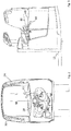
- Figure 1 shows an industrial truck 10 with a load part 12 (cf. Fig. 3 ) and a drive part 14.
- the load part 12 has two liftable load arms 16, which are only partially shown for a better overview.
- the load arms 16 can be raised to transport a load via a lifting device (not shown).
- the drive part 14 has an operating unit 18 which is designed as a multifunction steering wheel with numerous operating elements 20 for operating the industrial truck.
- a driver's stand platform 22 is provided, which is laterally bounded by side walls 24, 26.
- the side wall 26 has a handle 28 which is perpendicular extending handle portion 30 and a horizontally extending handle portion 32 has.
- the driver's stand platform 22, which is laterally surrounded by the side walls 24 and 26, has an entrance 36 on its side facing away from the load part. Opposite the entrance 36 is the end wall 38 in which the charging interface 40 is arranged.
- the charging interface 40 is arranged in the interior of the drive part and ends flush with the end wall 38.
- other configurations and delimitations for the driver's stand are also possible.
- a charging plug 42 with its cables 44 is inserted into the charging interface 40.
- the charging plug 42 can come from a charger or, in the case that a charger integrated on board is provided, be connected directly to a voltage source.
- FIG. 3 it is shown that the charging plug 42 is pushed obliquely from top to bottom into the end wall 38 along the insertion direction 46.
- the insertion direction 46 is inclined with respect to the horizontal 48. If the insertion process is carried out with the left hand, the operator has the option of holding onto the handle 30 with his right hand. For right-handers, a handle is also provided on the side wall 24 to hold on to.
- Fig. 2 shows the vehicle center longitudinal axis M, which is laterally offset with respect to the insertion direction L.
Landscapes
- Engineering & Computer Science (AREA)
- Transportation (AREA)
- Structural Engineering (AREA)
- Mechanical Engineering (AREA)
- Civil Engineering (AREA)
- Power Engineering (AREA)
- Life Sciences & Earth Sciences (AREA)
- Geology (AREA)
- Combustion & Propulsion (AREA)
- Chemical & Material Sciences (AREA)
- Electric Propulsion And Braking For Vehicles (AREA)
- Forklifts And Lifting Vehicles (AREA)
- Charge And Discharge Circuits For Batteries Or The Like (AREA)
Abstract
Description
- Die vorliegende Erfindung betrifft ein Flurförderzeug mit einer Ladeschnittstelle. Das erfindungsgemäße Flurförderzeug besitzt ein Lastteil und ein Antriebsteil, das eine Fahrerstandplattform aufweist. Die Fahrerstandplattform ist eine fest eingebaute Fahrerstandplattform, die einen Einstieg und mindestens eine Seitenwand aufweist.
- Aus
DE 10 2013 000 094 T5 ist ein Gegengewichtstapler mit Hubmast bekannt geworden, der eine Ladeschnittstelle innerhalb der Fahrzeugkabine besitzt. Nachteilig an dieser Anordnung der Ladeschnittstelle ist, dass keine Möglichkeit besteht das Ladekabel während des Ladevorgangs des Gegengewichtstaplers in definierter Weise aus dem Fahrzeug heraus zu führen, so dass die Gefahr einer Beschädigung des Ladekabels besteht. - Der Erfindung liegt die Aufgabe zugrunde ein Flurförderzeug mit einer Fahrerstandplattform bereitzustellen, dessen Ladeschnittstelle sicher und gut zugänglich angeordnet ist.
- Erfindungsgemäß wird die Aufgabe durch ein Flurförderzeug mit den Merkmalen aus Anspruch 1 gelöst. Vorteilhafte Ausgestaltungen bilden die Gegenstände der Unteransprüche.
- Das erfindungsgemäße Flurförderzeug besitzt ein Lastteil und ein Antriebsteil. Das Antriebsteil ist mit einer Fahrerstandplattform versehen, die von mindestens einer Seitenwand begrenzt ist. Ferner ist mindestens ein batteriegespeister elektrischer Antrieb vorgesehen. Für ein Wiederaufladen der Batterie in ihrem eingebauten Zustand ist eine Ladeschnittstelle vorgesehen. Ladeschnittstellen sind an sich bekannt, sie enthalten elektrische Kontakte, die von einem mit der Ladeschnittstelle zusammenwirkenden elektrischen Steckverbinder für einen Ladevorgang kontaktiert werden. Erfindungsgemäß ist vorgesehen, dass die Ladeschnittstelle an der dem Einstieg gegenüberliegenden Stirnwand vorgesehen ist. Hierdurch entstehen zwei besondere Vorteile: Erstens befindet sich die Ladeschnittstelle im Bereich der Fahrerstandplattform und damit im Inneren der Fahrzeugkontur. Hierdurch können die Flurförderzeuge bei einem Ladevorgang dicht nebeneinander stehen, ohne dass ein Risiko besteht, an den Ladestecker in der Ladeschnittstelle zu stoßen. Der zweite Vorteil der Anordnung der Ladeschnittstelle im Inneren der Fahrzeugkontur liegt in einer besonders ergonomischen Weise, wie der Ladestecker in die Ladeschnittstelle eingesetzt werden kann. Indem die Ladeschnittstelle gegenüber von dem Einstieg liegt, ist es möglich durch den Einstieg hindurch den Ladestecker in die Ladeschnittstelle zu stecken und auch wieder herauszuziehen.
- Bevorzugt ist eine Bedieneinheit für das Flurförderzeug an der Stirnwand angebracht. In dieser Anordnung tritt die Bedienperson durch den Eintritt auf die Fahrerstandplattform und steht vor der Bedieneinheit mit der Ladeschnittstelle direkt in Reichweite.
- In einer bevorzugten Ausgestaltung ist die Ladeschnittstelle außermittig bezogen auf die Fahrzeugmittelebene an der Stirnwand angeordnet. Die außermittige Anordnung erlaubt eine im besonderen Maße ergonomische Benutzung der Ladeschnittstelle beim Ein- und Ausstecken des Ladesteckers. Bevorzugt sind zueinander gegenüberliegende Seitenwände vorgesehen.
- In einer bevorzugten Weiterbildung ist mindestens ein Handgriff an einer der Seitenwände und/oder der Stirnwand derart angeordnet, dass er von einer vor der Fahrerstandplattform stehenden Bedienperson ergriffen werden kann, um einen Ladestecker einhändig in die Ladeschnittstelle einzuführen. Das Zusammenspiel zwischen Handgriff und einhändigem Einsetzen des Ladesteckers, erlaubt eine über die Schultern koordinierte Zug-Druckbewegung mit der eine notwendige Einsteckkraft für den Ladestecker aufgebracht wird.
- In einer weiteren bevorzugten Ausgestaltung besitzt die Ladeschnittstelle eine Steckrichtung, die aus der Horizontalen geneigt ist. Bevorzugt wird bei der Steckrichtung der Ladestecker schräg von oben nach unten in die Ladeschnittstelle eingeführt. Dies bedeutet, dass beim Einsetzen des Ladesteckers in die Ladeschnittstelle, ein Steckvorgang über das Körpergewicht der Bedienperson unterstützt werden kann. Diese Unterstützung erlaubt es in ergonomischer Weise die erforderliche Einsteckkraft für den Steckvorgang aufzubringen. Auch bei einem Herausziehen des Ladesteckers aus der Ladeschnittstelle, kann hier mit Unterstützung des Oberkörpers die erforderliche Kraft aufgebracht werden.
- In einer bevorzugten Ausgestaltung ist die Ladeschnittstelle mit einer Klappe ausgestattet. Die Klappe ist bei einem elektrischen Anschluss eines Ladesteckers geöffnet und ohne den Ladestecker verschließt die Klappe die Öffnung zu den elektrischen Kontakten der Ladeschnittstelle.
- In einer zweckmäßigen Weiterentwicklung ist ein Sensor vorgesehen, der eine Offen-Position der Klappe erfasst und diese an eine Fahrzeugsteuerung meldet. Die Fahrzeugsteuerung sperrt bei erfasster Offen-Position der Klappe eine oder mehrere vorbestimmte Fahrzeugfunktionen. Beispielsweise kann ein Starten und Wegfahren mit dem Flurförderzeug für eine geöffnete Klappe der Ladeschnittstelle gesperrt sein.
- In einer bevorzugten Weiterbildung ist die Ladeschnittstelle direkt oder mit einem Halter an der Batterie montiert und durch eine Durchbrechung in der Stirnwand zugänglich. Der Vorteil, die Ladeschnittstelle an der Batterie zu montieren besteht darin, dass an der Batterie eine ausreichend feste Montage erfolgen kann, um die Kräfte beim Ein- und Aussteckern aufzufangen. Weitere Vorteile der Montage der Ladeschnittstelle an der Batterie sind, dass für Wartung und Reparatur des Fahrzeugs die Batterie gemeinsam mit der Ladeschnittstelle ohne Lösen einer elektrischen Verbindung verschoben werden kann. Zudem können durch eine Befestigung an der Batterie andere raumfordernde Bauteile entfallen.
- Ein bevorzugtes Ausführungsbeispiel wird anhand der beiliegenden Figuren gezeigt. Es zeigen:
- Figur 1a, b
- ein Flurförderzeug mit der erfindungsgemäßen Ladeschnittstelle mit und ohne eingesetztem Ladestecker in einer Ansicht von schräg,
- Figur 2
- das Flurförderzeug aus
Figur 1 in einer Ansicht von oben und - Figur 3
- das Flurförderzeug aus
Fig. 2 in einer Ansicht von der Seite bei transparenter Seitenwand. -
Figur 1 zeigt ein Flurförderzeug 10 mit einem Lastteil 12 (vgl.Fig. 3 ) und einem Antriebsteil 14. Das Lastteil 12 besitzt zwei anhebbare Lastarme 16, die zur besseren Übersicht nur teilweise dargestellt sind. Über eine nicht dargestellte Hubeinrichtung können die Lastarme 16 zum Transport einer Last angehoben werden. - Das Antriebsteil 14 besitzt eine Bedieneinheit 18, die als ein Multifunktions-Lenkrad mit zahlreichen Bedienelementen 20 zur Bedienung des Flurförderzeugs ausgebildet ist. In dem vom Lastteil 12 fortweisenden Teil des Antriebsteils 14 ist eine Fahrerstandplattform 22 vorgesehen, die seitlich durch Seitenwände 24, 26 begrenzt ist. Die Seitenwand 26 besitzt einen Handgriff 28, der einen senkrecht verlaufenden Griffabschnitt 30 und einen horizontal verlaufenden Griffabschnitt 32 besitzt. Die von den Seitenwänden 24 und 26 seitlich umgebene Fahrerstandplattform 22 besitzt auf ihrer vom Lastteil fortweisenden Seite einen Einstieg 36. Dem Einstieg 36 gegenüber befindet sich die Stirnwand 38, in der die Ladeschnittstelle 40 angeordnet ist. Wie in
Figur 1a zu erkennen, ist die Ladeschnittstelle 40 im Inneren des Antriebsteils angeordnet und schließt mit der Stirnwand 38 bündig ab. Neben der dargestellten Anordnung mit zwei einander gegenüberliegenden Seitenwänden 24, 26 und einem von diesen begrenzten Einstieg 36 sind auch andere Konfigurationen und Begrenzungen für den Fahrerstandplatz möglich. - In
Fig. 1b ist in die Ladeschnittstelle 40 ein Ladestecker 42 mit seinen Kabeln 44 eingesetzt. Der Ladestecker 42 kann von einem Ladegerät stammen oder im Fall, dass ein an Bord integriertes Ladegerät vorgesehen ist, direkt mit einer Spannungsquelle verbunden sein. - In
Figur 3 dargestellt ist, dass der Ladestecker 42 entlang der Einsteckrichtung 46 schräg von oben nach unten in die Stirnwand 38 hineingedrückt wird. Die Einsteckrichtung 46 ist gegenüber der Horizontalen 48 geneigt. Wird der Einsteckvorgang mit der linken Hand ausgeführt, besteht für den Bediener die Möglichkeit sich mit der rechten Hand an dem Handgriff 30 festzuhalten. Für Rechtshänder ist an der Seitenwand 24 ebenfalls ein Griff zum Festhalten vorgesehen. -
Fig. 2 zeigt die Fahrzeugmittenlängsachse M, die gegenüber der Einsteckrichtung L seitlich versetzt ist. -
- 10
- Flurförderzeug
- 12
- Lastteil
- 14
- Antrieb steil
- 16
- Lastarm
- 18
- Bedienelement
- 20
- Bedienelement
- 22
- Fahrerstandplattform
- 24
- Seitenwand
- 26
- Seitenwand
- 28
- Handgriff
- 30
- Griffabschnitt
- 32
- Griffabschnitt
- 36
- Einstieg
- 38
- Stirnwand
- 40
- Ladeschnittstelle
- 42
- Ladestecker
- 44
- Kabel
- 46
- Einsteckrichtung
- 48
- Horizontale
Claims (9)
- Flurförderzeug (10) mit einem Lastteil (12) und einem Antriebsteil (14), das eine Fahrerstandplattform (22) aufweist, die einen Einstieg (36) und mindestens eine Seitenwand (24, 26) aufweist, wobei die Fahrerstandplattform (22) auch eine dem Einstieg (36) gegenüberliegende Stirnwand (38) aufweist und mindestens ein batteriegespeister elektrischer Antrieb vorgesehen ist, wobei die Batterie über eine Ladeschnittstelle (40) in ihrem eingebauten Zustand aufgeladen werden kann, dadurch gekennzeichnet, dass die Ladeschnittstelle (40) an der dem Einstieg (36) gegenüberliegenden Stirnwand (38) angeordnet ist.
- Flurförderzeug nach Anspruch 1, dadurch gekennzeichnet, dass eine Bedieneinheit(18) oberhalb der Stirnwand (38) angebracht ist.
- Flurförderzeug (10) nach Anspruch 1 oder 2, dadurch gekennzeichnet, dass die Ladeschnittstelle (40) außermittig bezogen auf eine Fahrzeugmittelebene (M) an der Stirnwand (38) angeordnet ist.
- Flurförderzeug nach einem der Ansprüche 1 bis 3, dadurch gekennzeichnet, dass der Einstieg (36) seitlich von zwei Seitenwänden (24, 26) begrenzt ist.
- Flurförderzeug (10) nach einem der Ansprüche 1 bis 4, dadurch gekennzeichnet, dass mindestens ein Handgriff (28) an einer der Seitenwände (24, 26) und/oder der Stirnwand (38) derart angeordnet ist, dass er von einer vor der Fahrerstandplattform (22) stehenden Bedienperson ergriffen werden kann, um einen Ladestecker (42) einhändig in die Ladeschnittstelle (40) einzuführen.
- Flurförderzeug (10) nach einem der Ansprüche 1 bis 5, dadurch gekennzeichnet, dass die Ladeschnittstelle (40) eine Steckrichtung (46) besitzt, die aus der Horizontalen (48) geneigt ist, wobei ein Einsteckvorgang schräg von oben nach unten erfolgt.
- Flurförderzeug (10) nach einem der Ansprüche 1 bis 6, dadurch gekennzeichnet, dass die Ladeschnittstelle (40) eine Klappe aufweist, die bei einem elektrischen Anschluss eines Ladesteckers (42) geöffnet und ohne Ladestecker (42) den Eingang zu elektrischen Kontakten in der Ladeschnittstelle (40) verschließt.
- Flurförderzeug (10) nach Anspruch 7, dadurch gekennzeichnet, dass ein Sensor vorgesehen ist, der eine Offen-Position der Klappe und/oder einen gesteckten Ladestecker (24) erfasst und diese an eine Fahrzeugsteuerung meldet, die bei einer Meldung des Sensors eine oder mehrere vorbestimmte Fahrzeugfunktionen sperrt.
- Flurförderzeug (10) nach einem der Ansprüche 1 bis 8, dadurch gekennzeichnet, dass die Ladeschnittstelle (40) an der Batterie montiert ist und die Stirnwand (38) eine Durchbrechung zur Ladeschnittstelle (40) hin aufweist.
Applications Claiming Priority (1)
| Application Number | Priority Date | Filing Date | Title |
|---|---|---|---|
| DE102019101922.2A DE102019101922A1 (de) | 2019-01-25 | 2019-01-25 | Flurförderzeug mit einer Ladeschnittstelle |
Publications (2)
| Publication Number | Publication Date |
|---|---|
| EP3693327A1 true EP3693327A1 (de) | 2020-08-12 |
| EP3693327B1 EP3693327B1 (de) | 2024-08-28 |
Family
ID=69191898
Family Applications (1)
| Application Number | Title | Priority Date | Filing Date |
|---|---|---|---|
| EP20153491.4A Active EP3693327B1 (de) | 2019-01-25 | 2020-01-24 | Flurförderzeug mit einer ladeschnittstelle |
Country Status (2)
| Country | Link |
|---|---|
| EP (1) | EP3693327B1 (de) |
| DE (1) | DE102019101922A1 (de) |
Citations (4)
| Publication number | Priority date | Publication date | Assignee | Title |
|---|---|---|---|---|
| DE102011000094A1 (de) * | 2011-01-11 | 2012-07-12 | Huf Hülsbeck & Fürst Gmbh & Co. Kg | System zur Zugriffskontrolle auf eine Fahrzeugladeeinrichtung |
| JP2012201461A (ja) * | 2011-03-25 | 2012-10-22 | Nippon Yusoki Co Ltd | バッテリ式フォークリフトのための充電プラグ |
| DE112013000094T5 (de) * | 2013-08-02 | 2015-07-23 | Komatsu Ltd. | Arbeitsfahrzeug |
| EP3418248A1 (de) * | 2017-06-22 | 2018-12-26 | Jungheinrich Aktiengesellschaft | Flurförderzeug mit rückhaltevorrichtung |
Family Cites Families (3)
| Publication number | Priority date | Publication date | Assignee | Title |
|---|---|---|---|---|
| DE102008033990A1 (de) * | 2008-07-16 | 2010-01-21 | Jungheinrich Aktiengesellschaft | Flurförderzeug und separates Arbeitsmittel zum Betrieb eines Flurförderzeugs |
| DE102015109081A1 (de) * | 2015-06-09 | 2016-12-15 | Linde Material Handling Gmbh | Flurförderzeug mit Ladesteckerverbindung |
| DE102017111943B4 (de) * | 2017-05-31 | 2025-12-31 | Jungheinrich Aktiengesellschaft | Schnittstellensystem für ein Flurförderzeug |
-
2019
- 2019-01-25 DE DE102019101922.2A patent/DE102019101922A1/de not_active Withdrawn
-
2020
- 2020-01-24 EP EP20153491.4A patent/EP3693327B1/de active Active
Patent Citations (4)
| Publication number | Priority date | Publication date | Assignee | Title |
|---|---|---|---|---|
| DE102011000094A1 (de) * | 2011-01-11 | 2012-07-12 | Huf Hülsbeck & Fürst Gmbh & Co. Kg | System zur Zugriffskontrolle auf eine Fahrzeugladeeinrichtung |
| JP2012201461A (ja) * | 2011-03-25 | 2012-10-22 | Nippon Yusoki Co Ltd | バッテリ式フォークリフトのための充電プラグ |
| DE112013000094T5 (de) * | 2013-08-02 | 2015-07-23 | Komatsu Ltd. | Arbeitsfahrzeug |
| EP3418248A1 (de) * | 2017-06-22 | 2018-12-26 | Jungheinrich Aktiengesellschaft | Flurförderzeug mit rückhaltevorrichtung |
Also Published As
| Publication number | Publication date |
|---|---|
| DE102019101922A1 (de) | 2020-07-30 |
| EP3693327B1 (de) | 2024-08-28 |
Similar Documents
| Publication | Publication Date | Title |
|---|---|---|
| DE102014011843B4 (de) | Ladeanschlussvorrichtung für einen Kraftwagen und Kraftwagen mit einer Ladeanschlussvorrichtung | |
| EP2018989B1 (de) | Hubwagen mit einem Batteriefach und einer Batterie | |
| DE102019203193A1 (de) | Steckverbinderanordnung zum Verbinden und Trennen elektrischer Leitungen | |
| DE102015122038B4 (de) | Steckverbinderteil mit einem Abdeckelement | |
| DE102019130551B4 (de) | Fahrzeugeinheit mit einem Ladeanschluss und Ladesystem zum Laden einer Batterie eines Elektrofahrzeugs | |
| DE102012022101A1 (de) | Anschlussvorrichtung zum Laden eines elektrisch betreibbaren Kraftwagens | |
| DE102010048384A1 (de) | Kraftfahrzeug | |
| DE102009010852A1 (de) | Stützstruktur einer Fahrzeugstromleitung | |
| EP2505544B1 (de) | Hubwagen mit einem verschliessbaren Batteriefach | |
| DE202019001786U1 (de) | Abnehmbares Steckmodul für Materialhandhabungsfahrzeuge | |
| WO2012048805A2 (de) | Vorrichtung zum verbinden eines fahrzeugs mit einer steckdose | |
| DE102015109081A1 (de) | Flurförderzeug mit Ladesteckerverbindung | |
| DE112020007746T5 (de) | Arbeitsfahrzeug | |
| DE102008034782B4 (de) | Flurförderzeug, insbesondere Gegengewichtsgabelstapler | |
| DE102012014376A1 (de) | Kraftfahrzeug-Tank mit Freiraum für Energiespeichervorrichtung | |
| DE102019122427A1 (de) | Karosserie, Baugruppe und Elektrokraftfahrzeug | |
| DE10241418A1 (de) | Flurförderzeug mit einer seitlichen Batterieentnahmeöffnung | |
| DE102019115601A1 (de) | Ladevorrichtung zum Laden einer Batterie eines Kraftfahrzeugs | |
| DE102011116746A1 (de) | Kraftwagen mit einer Leitungseinrichtung | |
| EP0014176A1 (de) | Elektrowagen | |
| DE60115484T2 (de) | System zum zweiseitigem laden von lastkraftwagen | |
| DE102012105456A1 (de) | Flurförderzeug mit einem seitlichen Wechsel einer Energieversorgungseinheit | |
| EP3693327B1 (de) | Flurförderzeug mit einer ladeschnittstelle | |
| EP0840687A1 (de) | Dachcontainer | |
| EP3517481A1 (de) | Flurförderzeug mit einem elektrischen steckverbinder |
Legal Events
| Date | Code | Title | Description |
|---|---|---|---|
| PUAI | Public reference made under article 153(3) epc to a published international application that has entered the european phase |
Free format text: ORIGINAL CODE: 0009012 |
|
| STAA | Information on the status of an ep patent application or granted ep patent |
Free format text: STATUS: THE APPLICATION HAS BEEN PUBLISHED |
|
| AK | Designated contracting states |
Kind code of ref document: A1 Designated state(s): AL AT BE BG CH CY CZ DE DK EE ES FI FR GB GR HR HU IE IS IT LI LT LU LV MC MK MT NL NO PL PT RO RS SE SI SK SM TR |
|
| AX | Request for extension of the european patent |
Extension state: BA ME |
|
| STAA | Information on the status of an ep patent application or granted ep patent |
Free format text: STATUS: REQUEST FOR EXAMINATION WAS MADE |
|
| 17P | Request for examination filed |
Effective date: 20210129 |
|
| RBV | Designated contracting states (corrected) |
Designated state(s): AL AT BE BG CH CY CZ DE DK EE ES FI FR GB GR HR HU IE IS IT LI LT LU LV MC MK MT NL NO PL PT RO RS SE SI SK SM TR |
|
| P01 | Opt-out of the competence of the unified patent court (upc) registered |
Effective date: 20230628 |
|
| GRAP | Despatch of communication of intention to grant a patent |
Free format text: ORIGINAL CODE: EPIDOSNIGR1 |
|
| RIC1 | Information provided on ipc code assigned before grant |
Ipc: B60L 53/14 20190101ALI20230925BHEP Ipc: B60L 53/16 20190101ALI20230925BHEP Ipc: B66F 9/24 20060101ALI20230925BHEP Ipc: B66F 9/075 20060101AFI20230925BHEP |
|
| STAA | Information on the status of an ep patent application or granted ep patent |
Free format text: STATUS: GRANT OF PATENT IS INTENDED |
|
| INTG | Intention to grant announced |
Effective date: 20231102 |
|
| GRAJ | Information related to disapproval of communication of intention to grant by the applicant or resumption of examination proceedings by the epo deleted |
Free format text: ORIGINAL CODE: EPIDOSDIGR1 |
|
| STAA | Information on the status of an ep patent application or granted ep patent |
Free format text: STATUS: REQUEST FOR EXAMINATION WAS MADE |
|
| INTC | Intention to grant announced (deleted) | ||
| GRAP | Despatch of communication of intention to grant a patent |
Free format text: ORIGINAL CODE: EPIDOSNIGR1 |
|
| STAA | Information on the status of an ep patent application or granted ep patent |
Free format text: STATUS: GRANT OF PATENT IS INTENDED |
|
| INTG | Intention to grant announced |
Effective date: 20240415 |
|
| GRAS | Grant fee paid |
Free format text: ORIGINAL CODE: EPIDOSNIGR3 |
|
| GRAA | (expected) grant |
Free format text: ORIGINAL CODE: 0009210 |
|
| STAA | Information on the status of an ep patent application or granted ep patent |
Free format text: STATUS: THE PATENT HAS BEEN GRANTED |
|
| AK | Designated contracting states |
Kind code of ref document: B1 Designated state(s): AL AT BE BG CH CY CZ DE DK EE ES FI FR GB GR HR HU IE IS IT LI LT LU LV MC MK MT NL NO PL PT RO RS SE SI SK SM TR |
|
| REG | Reference to a national code |
Ref country code: CH Ref legal event code: EP |
|
| REG | Reference to a national code |
Ref country code: DE Ref legal event code: R096 Ref document number: 502020008986 Country of ref document: DE |
|
| REG | Reference to a national code |
Ref country code: IE Ref legal event code: FG4D Free format text: LANGUAGE OF EP DOCUMENT: GERMAN |
|
| REG | Reference to a national code |
Ref country code: LT Ref legal event code: MG9D |
|
| PG25 | Lapsed in a contracting state [announced via postgrant information from national office to epo] |
Ref country code: NO Free format text: LAPSE BECAUSE OF FAILURE TO SUBMIT A TRANSLATION OF THE DESCRIPTION OR TO PAY THE FEE WITHIN THE PRESCRIBED TIME-LIMIT Effective date: 20241128 |
|
| PG25 | Lapsed in a contracting state [announced via postgrant information from national office to epo] |
Ref country code: NL Free format text: LAPSE BECAUSE OF FAILURE TO SUBMIT A TRANSLATION OF THE DESCRIPTION OR TO PAY THE FEE WITHIN THE PRESCRIBED TIME-LIMIT Effective date: 20240828 Ref country code: PL Free format text: LAPSE BECAUSE OF FAILURE TO SUBMIT A TRANSLATION OF THE DESCRIPTION OR TO PAY THE FEE WITHIN THE PRESCRIBED TIME-LIMIT Effective date: 20240828 Ref country code: FI Free format text: LAPSE BECAUSE OF FAILURE TO SUBMIT A TRANSLATION OF THE DESCRIPTION OR TO PAY THE FEE WITHIN THE PRESCRIBED TIME-LIMIT Effective date: 20240828 Ref country code: GR Free format text: LAPSE BECAUSE OF FAILURE TO SUBMIT A TRANSLATION OF THE DESCRIPTION OR TO PAY THE FEE WITHIN THE PRESCRIBED TIME-LIMIT Effective date: 20241129 Ref country code: PT Free format text: LAPSE BECAUSE OF FAILURE TO SUBMIT A TRANSLATION OF THE DESCRIPTION OR TO PAY THE FEE WITHIN THE PRESCRIBED TIME-LIMIT Effective date: 20241230 |
|
| PG25 | Lapsed in a contracting state [announced via postgrant information from national office to epo] |
Ref country code: BG Free format text: LAPSE BECAUSE OF FAILURE TO SUBMIT A TRANSLATION OF THE DESCRIPTION OR TO PAY THE FEE WITHIN THE PRESCRIBED TIME-LIMIT Effective date: 20240828 |
|
| PG25 | Lapsed in a contracting state [announced via postgrant information from national office to epo] |
Ref country code: LV Free format text: LAPSE BECAUSE OF FAILURE TO SUBMIT A TRANSLATION OF THE DESCRIPTION OR TO PAY THE FEE WITHIN THE PRESCRIBED TIME-LIMIT Effective date: 20240828 |
|
| REG | Reference to a national code |
Ref country code: NL Ref legal event code: MP Effective date: 20240828 |
|
| PG25 | Lapsed in a contracting state [announced via postgrant information from national office to epo] |
Ref country code: IS Free format text: LAPSE BECAUSE OF FAILURE TO SUBMIT A TRANSLATION OF THE DESCRIPTION OR TO PAY THE FEE WITHIN THE PRESCRIBED TIME-LIMIT Effective date: 20241228 |
|
| PG25 | Lapsed in a contracting state [announced via postgrant information from national office to epo] |
Ref country code: HR Free format text: LAPSE BECAUSE OF FAILURE TO SUBMIT A TRANSLATION OF THE DESCRIPTION OR TO PAY THE FEE WITHIN THE PRESCRIBED TIME-LIMIT Effective date: 20240828 |
|
| PG25 | Lapsed in a contracting state [announced via postgrant information from national office to epo] |
Ref country code: RS Free format text: LAPSE BECAUSE OF FAILURE TO SUBMIT A TRANSLATION OF THE DESCRIPTION OR TO PAY THE FEE WITHIN THE PRESCRIBED TIME-LIMIT Effective date: 20241128 Ref country code: ES Free format text: LAPSE BECAUSE OF FAILURE TO SUBMIT A TRANSLATION OF THE DESCRIPTION OR TO PAY THE FEE WITHIN THE PRESCRIBED TIME-LIMIT Effective date: 20240828 |
|
| PG25 | Lapsed in a contracting state [announced via postgrant information from national office to epo] |
Ref country code: RS Free format text: LAPSE BECAUSE OF FAILURE TO SUBMIT A TRANSLATION OF THE DESCRIPTION OR TO PAY THE FEE WITHIN THE PRESCRIBED TIME-LIMIT Effective date: 20241128 Ref country code: PT Free format text: LAPSE BECAUSE OF FAILURE TO SUBMIT A TRANSLATION OF THE DESCRIPTION OR TO PAY THE FEE WITHIN THE PRESCRIBED TIME-LIMIT Effective date: 20241230 Ref country code: PL Free format text: LAPSE BECAUSE OF FAILURE TO SUBMIT A TRANSLATION OF THE DESCRIPTION OR TO PAY THE FEE WITHIN THE PRESCRIBED TIME-LIMIT Effective date: 20240828 Ref country code: NO Free format text: LAPSE BECAUSE OF FAILURE TO SUBMIT A TRANSLATION OF THE DESCRIPTION OR TO PAY THE FEE WITHIN THE PRESCRIBED TIME-LIMIT Effective date: 20241128 Ref country code: NL Free format text: LAPSE BECAUSE OF FAILURE TO SUBMIT A TRANSLATION OF THE DESCRIPTION OR TO PAY THE FEE WITHIN THE PRESCRIBED TIME-LIMIT Effective date: 20240828 Ref country code: LV Free format text: LAPSE BECAUSE OF FAILURE TO SUBMIT A TRANSLATION OF THE DESCRIPTION OR TO PAY THE FEE WITHIN THE PRESCRIBED TIME-LIMIT Effective date: 20240828 Ref country code: IS Free format text: LAPSE BECAUSE OF FAILURE TO SUBMIT A TRANSLATION OF THE DESCRIPTION OR TO PAY THE FEE WITHIN THE PRESCRIBED TIME-LIMIT Effective date: 20241228 Ref country code: HR Free format text: LAPSE BECAUSE OF FAILURE TO SUBMIT A TRANSLATION OF THE DESCRIPTION OR TO PAY THE FEE WITHIN THE PRESCRIBED TIME-LIMIT Effective date: 20240828 Ref country code: GR Free format text: LAPSE BECAUSE OF FAILURE TO SUBMIT A TRANSLATION OF THE DESCRIPTION OR TO PAY THE FEE WITHIN THE PRESCRIBED TIME-LIMIT Effective date: 20241129 Ref country code: FI Free format text: LAPSE BECAUSE OF FAILURE TO SUBMIT A TRANSLATION OF THE DESCRIPTION OR TO PAY THE FEE WITHIN THE PRESCRIBED TIME-LIMIT Effective date: 20240828 Ref country code: ES Free format text: LAPSE BECAUSE OF FAILURE TO SUBMIT A TRANSLATION OF THE DESCRIPTION OR TO PAY THE FEE WITHIN THE PRESCRIBED TIME-LIMIT Effective date: 20240828 Ref country code: BG Free format text: LAPSE BECAUSE OF FAILURE TO SUBMIT A TRANSLATION OF THE DESCRIPTION OR TO PAY THE FEE WITHIN THE PRESCRIBED TIME-LIMIT Effective date: 20240828 |
|
| PG25 | Lapsed in a contracting state [announced via postgrant information from national office to epo] |
Ref country code: DK Free format text: LAPSE BECAUSE OF FAILURE TO SUBMIT A TRANSLATION OF THE DESCRIPTION OR TO PAY THE FEE WITHIN THE PRESCRIBED TIME-LIMIT Effective date: 20240828 Ref country code: SM Free format text: LAPSE BECAUSE OF FAILURE TO SUBMIT A TRANSLATION OF THE DESCRIPTION OR TO PAY THE FEE WITHIN THE PRESCRIBED TIME-LIMIT Effective date: 20240828 Ref country code: RO Free format text: LAPSE BECAUSE OF FAILURE TO SUBMIT A TRANSLATION OF THE DESCRIPTION OR TO PAY THE FEE WITHIN THE PRESCRIBED TIME-LIMIT Effective date: 20240828 |
|
| PG25 | Lapsed in a contracting state [announced via postgrant information from national office to epo] |
Ref country code: EE Free format text: LAPSE BECAUSE OF FAILURE TO SUBMIT A TRANSLATION OF THE DESCRIPTION OR TO PAY THE FEE WITHIN THE PRESCRIBED TIME-LIMIT Effective date: 20240828 |
|
| PG25 | Lapsed in a contracting state [announced via postgrant information from national office to epo] |
Ref country code: CZ Free format text: LAPSE BECAUSE OF FAILURE TO SUBMIT A TRANSLATION OF THE DESCRIPTION OR TO PAY THE FEE WITHIN THE PRESCRIBED TIME-LIMIT Effective date: 20240828 |
|
| PG25 | Lapsed in a contracting state [announced via postgrant information from national office to epo] |
Ref country code: SK Free format text: LAPSE BECAUSE OF FAILURE TO SUBMIT A TRANSLATION OF THE DESCRIPTION OR TO PAY THE FEE WITHIN THE PRESCRIBED TIME-LIMIT Effective date: 20240828 |
|
| REG | Reference to a national code |
Ref country code: DE Ref legal event code: R097 Ref document number: 502020008986 Country of ref document: DE |
|
| PLBE | No opposition filed within time limit |
Free format text: ORIGINAL CODE: 0009261 |
|
| STAA | Information on the status of an ep patent application or granted ep patent |
Free format text: STATUS: NO OPPOSITION FILED WITHIN TIME LIMIT |
|
| 26N | No opposition filed |
Effective date: 20250530 |
|
| REG | Reference to a national code |
Ref country code: CH Ref legal event code: PL |
|
| PG25 | Lapsed in a contracting state [announced via postgrant information from national office to epo] |
Ref country code: SE Free format text: LAPSE BECAUSE OF FAILURE TO SUBMIT A TRANSLATION OF THE DESCRIPTION OR TO PAY THE FEE WITHIN THE PRESCRIBED TIME-LIMIT Effective date: 20240828 |
|
| PG25 | Lapsed in a contracting state [announced via postgrant information from national office to epo] |
Ref country code: MC Free format text: LAPSE BECAUSE OF FAILURE TO SUBMIT A TRANSLATION OF THE DESCRIPTION OR TO PAY THE FEE WITHIN THE PRESCRIBED TIME-LIMIT Effective date: 20240828 Ref country code: LU Free format text: LAPSE BECAUSE OF NON-PAYMENT OF DUE FEES Effective date: 20250124 |
|
| GBPC | Gb: european patent ceased through non-payment of renewal fee |
Effective date: 20250124 |
|
| PG25 | Lapsed in a contracting state [announced via postgrant information from national office to epo] |
Ref country code: GB Free format text: LAPSE BECAUSE OF NON-PAYMENT OF DUE FEES Effective date: 20250124 Ref country code: BE Free format text: LAPSE BECAUSE OF NON-PAYMENT OF DUE FEES Effective date: 20250131 |
|
| PG25 | Lapsed in a contracting state [announced via postgrant information from national office to epo] |
Ref country code: CH Free format text: LAPSE BECAUSE OF NON-PAYMENT OF DUE FEES Effective date: 20250131 |
|
| REG | Reference to a national code |
Ref country code: BE Ref legal event code: MM Effective date: 20250131 |
|
| PG25 | Lapsed in a contracting state [announced via postgrant information from national office to epo] |
Ref country code: IE Free format text: LAPSE BECAUSE OF NON-PAYMENT OF DUE FEES Effective date: 20250124 |
|
| REG | Reference to a national code |
Ref country code: AT Ref legal event code: MM01 Ref document number: 1717798 Country of ref document: AT Kind code of ref document: T Effective date: 20250124 |
|
| PGFP | Annual fee paid to national office [announced via postgrant information from national office to epo] |
Ref country code: DE Payment date: 20260120 Year of fee payment: 7 |
|
| PG25 | Lapsed in a contracting state [announced via postgrant information from national office to epo] |
Ref country code: AT Free format text: LAPSE BECAUSE OF NON-PAYMENT OF DUE FEES Effective date: 20250124 |
|
| PGFP | Annual fee paid to national office [announced via postgrant information from national office to epo] |
Ref country code: IT Payment date: 20260130 Year of fee payment: 7 |
|
| PGFP | Annual fee paid to national office [announced via postgrant information from national office to epo] |
Ref country code: FR Payment date: 20260128 Year of fee payment: 7 |
|
| PG25 | Lapsed in a contracting state [announced via postgrant information from national office to epo] |
Ref country code: CY Free format text: LAPSE BECAUSE OF FAILURE TO SUBMIT A TRANSLATION OF THE DESCRIPTION OR TO PAY THE FEE WITHIN THE PRESCRIBED TIME-LIMIT Effective date: 20240828 |
|
| PG25 | Lapsed in a contracting state [announced via postgrant information from national office to epo] |
Ref country code: TR Free format text: LAPSE BECAUSE OF FAILURE TO SUBMIT A TRANSLATION OF THE DESCRIPTION OR TO PAY THE FEE WITHIN THE PRESCRIBED TIME-LIMIT Effective date: 20240828 |
|
| PG25 | Lapsed in a contracting state [announced via postgrant information from national office to epo] |
Ref country code: LT Free format text: LAPSE BECAUSE OF FAILURE TO SUBMIT A TRANSLATION OF THE DESCRIPTION OR TO PAY THE FEE WITHIN THE PRESCRIBED TIME-LIMIT Effective date: 20240828 |