EP3692344B1 - Load cell lift-off protection device - Google Patents
Load cell lift-off protection device Download PDFInfo
- Publication number
- EP3692344B1 EP3692344B1 EP18782298.6A EP18782298A EP3692344B1 EP 3692344 B1 EP3692344 B1 EP 3692344B1 EP 18782298 A EP18782298 A EP 18782298A EP 3692344 B1 EP3692344 B1 EP 3692344B1
- Authority
- EP
- European Patent Office
- Prior art keywords
- load cell
- load
- cell body
- transmission member
- assembly according
- Prior art date
- Legal status (The legal status is an assumption and is not a legal conclusion. Google has not performed a legal analysis and makes no representation as to the accuracy of the status listed.)
- Active
Links
Images


Classifications
-
- G—PHYSICS
- G01—MEASURING; TESTING
- G01G—WEIGHING
- G01G21/00—Details of weighing apparatus
- G01G21/24—Guides or linkages for ensuring parallel motion of the weigh-pans
-
- G—PHYSICS
- G01—MEASURING; TESTING
- G01G—WEIGHING
- G01G21/00—Details of weighing apparatus
- G01G21/23—Support or suspension of weighing platforms
-
- G—PHYSICS
- G01—MEASURING; TESTING
- G01G—WEIGHING
- G01G23/00—Auxiliary devices for weighing apparatus
- G01G23/002—Means for correcting for obliquity of mounting
-
- G—PHYSICS
- G01—MEASURING; TESTING
- G01G—WEIGHING
- G01G23/00—Auxiliary devices for weighing apparatus
- G01G23/06—Means for damping oscillations, e.g. of weigh beams
- G01G23/12—Means for damping oscillations, e.g. of weigh beams specially adapted for preventing oscillations due to movement of the load
-
- G—PHYSICS
- G01—MEASURING; TESTING
- G01L—MEASURING FORCE, STRESS, TORQUE, WORK, MECHANICAL POWER, MECHANICAL EFFICIENCY, OR FLUID PRESSURE
- G01L1/00—Measuring force or stress, in general
- G01L1/26—Auxiliary measures taken, or devices used, in connection with the measurement of force, e.g. for preventing influence of transverse components of force, for preventing overload
Definitions
- the invention relates to a device for securing that the connection between a load and a load cell is ensured even under adverse operational conditions with negative loads on a load cell.
- the invention relates more specifically to installations where load cells are used for weighing on silos, mixing machinery etc. and where there is a risk of the weighed installation accidentally being tilted or falling over.
- Figure 1 show a commonly used way of securing a weighing installation against tilting
- 1 is the load cell
- 2 is a concrete surface
- 3 is a load introducing part
- 4 is a part of the structure of the weighed installation.
- the two bolts 5, which are fastened in the concrete surface 2 are passing through two holes 6 in the beam 7, which is welded to the structure member 4.
- the nuts 8 are securing that the weighed installation cannot be lifted off the load cell 1.
- the accuracy of this commonly used weighing solution is totally dependent on that the beam 7 is not in contact with the bolts 5 nor the nuts 8. These conditions are often violated in practice by the installation of the weighing system and later in use. Besides this obvious problem, this solution with the rather long bolts, is not stable with strong horizontal forces, which for example are seen during earthquakes.
- Another common solution is to secure the weighed installation by one or more bolts mounted in the upper surface of the load cell, but this solution will invariably introduce parasitic forces into the load cell, lowering the accuracy.
- the object of the invention is to increase the security of a weighed installation which is obtained by locking the weighed installation to the load cell with locking members which are ensuring a reliable function and which are not introducing parasitic forces into the load cell.
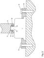
- the load cell 1 is clamped down on the surface 2 by the bolts 9 securing the ring or plate 10.
- the part 4 of the structure of the weighed installation is resting on the spherical upper surface 11 of the force introduction part 12 of the load cell 1.
- the locking members 13 are placed in the groove 14 of the part 4 and the groove 15 of the force introduction part 12.
- the locking members 13, which are shown as possibly being spherical balls are introduced into the grooves 14 and 15 through the opening 16 in the part 4.
- the grooves are preferably completely filled with locking members to ensure that the highest possible load can be taken up by the load cell lift-off protection device in critical situations.
- the opening 16 is preferably closed by a threaded screw and additional openings 16 are preferably provided for a possible later easy removal of the locking members 13 when performing service on the load cell installation.
- the locking members 13 are preferably magnetic for even more easy removal.
- the height of the groove 14 and or possibly the groove 15 are higher than the height or diameter of the locking member 13. This allows the part 4 to tilt to a certain degree without introducing parasitic bending moments into the load cell as the load applied to the load cell is just shifting on the spherical surface 11 of the force introduction part 12.
- the locking members 13 are shown as locking members fitting into the essentially rectangular grooves 14 and 15, which may have height which is equal to or preferably higher than the height of the locking members 13.
- Figure 5 show locking members in the form of cylindrical rollers with a height fitting into the grooves 14 and 15
- figure 6 show locking members with a height fitting into the grooves 14 and 15 and with an inner and outer radius fitting into respectively the grooves 15 and 14.
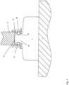
- Fig. 7 shows a sectional view of a load cell assembly, where a first end of the load cell 1 may be attached (not shown) to the base 2, where the load cell is provided with a second end, the force introduction part 12, configured to receive a load from a load transmission member 4.
- the load transmission member is provided with a recess 17 having a size that is larger than the outer diameter of the second end of the load cell, so that the second end 12 may be introduced into the recess of the load transmission member.
- the peripheral edge of the second end 12 may be provided with one or more grooves, that may be adapted to receive an intermediate coupling element 13, where the intermediate coupling element is locked to the side walls of the recess 17.
- the coupling element 13 may be adapted to move in a radial direction, so that prior to the placement of the load transmission member onto the load cell, the coupling elements are retracted, allowing the side walls of the recess to slip over the second end of the load cell.
- a locking sleeve 18 may be utilized to press the coupling members 13 in a radial inwards direction, allowing the coupling members to engage with the grooves, in order to prevent the load transmission member to be released from the load cell. I.e. the inner diameter of the coupling members, when engaged is smaller than the outer diameter of the grooves, so that the upper edge of the grooves will engage the coupling elements 13 if the load transmission member is pulled in a direction away from the load cell 1.
- the grooves are configured to have a vertical dimension that is larger than the vertical dimensions of the coupling element, allowing the coupling element to have a margin of movement (latitude) between the lower edge of the groove and the upper edge of the groove.
- the load transmission member 4 will be capable of tilting away from a vertical axis (central axis of the load cell) without the coupling member to come into engagement with the upper edge of the groove. I.e. that the coupling element may move in a vertical direction within the groove without engaging the groove. This ensures that the angled movement of the load transmission member will not transfer any interfering forces into the load cell, such as forces that are in a direction other than in the vertical direction. Thus, the forces that effect the movement of the load transferring member to tilt, will not affect the second end of the load cell, ensuring that parasitic forces applied to the load transmission member are isolated from the load cell.
- the attachment between the load transmission member and the second end of the load cell in a direction towards the load cell is ensured between the contact surface of the load cell and the contact surface of the load transmission member, so that the load applied to the load transmission member to be measured by the load cell is directly transmitted to the load cell.
- the attachment in the opposite direction is however secured by the coupling element, allowing some leeway of movement between the load cell and load transmission member in an upwards direction (vertical direction away from the load cell, as well as a tilting movement of the load transmission member, relative to the load cell.
Landscapes
- Physics & Mathematics (AREA)
- General Physics & Mathematics (AREA)
- Measurement Of Force In General (AREA)
- Forklifts And Lifting Vehicles (AREA)
Applications Claiming Priority (2)
| Application Number | Priority Date | Filing Date | Title |
|---|---|---|---|
| DKPA201700548 | 2017-10-02 | ||
| PCT/DK2018/000091 WO2019068292A1 (en) | 2017-10-02 | 2018-09-07 | DEVICE FOR PROTECTING AGAINST LIFTING FOR LOAD CELL |
Publications (2)
| Publication Number | Publication Date |
|---|---|
| EP3692344A1 EP3692344A1 (en) | 2020-08-12 |
| EP3692344B1 true EP3692344B1 (en) | 2023-05-17 |
Family
ID=63762161
Family Applications (1)
| Application Number | Title | Priority Date | Filing Date |
|---|---|---|---|
| EP18782298.6A Active EP3692344B1 (en) | 2017-10-02 | 2018-09-07 | Load cell lift-off protection device |
Country Status (5)
| Country | Link |
|---|---|
| US (1) | US11408763B2 (enExample) |
| EP (1) | EP3692344B1 (enExample) |
| JP (1) | JP7233738B2 (enExample) |
| CN (1) | CN111356906B (enExample) |
| WO (1) | WO2019068292A1 (enExample) |
Families Citing this family (3)
| Publication number | Priority date | Publication date | Assignee | Title |
|---|---|---|---|---|
| CN207751564U (zh) * | 2017-08-07 | 2018-08-21 | 永正传感(杭州)有限公司 | 超低模块称重传感器 |
| ES3059143T3 (en) | 2021-10-21 | 2026-03-19 | Eilersen Calibration Solutions Aps | A calibration device for weighing systems |
| EP4644847A1 (en) | 2024-04-30 | 2025-11-05 | Eilersen Electric Digital Systems IP ApS | A load cell assembly |
Citations (1)
| Publication number | Priority date | Publication date | Assignee | Title |
|---|---|---|---|---|
| DE102016118046A1 (de) * | 2016-09-23 | 2018-03-29 | Minebea Intec GmbH | Hygienischer Pendellastfuß |
Family Cites Families (17)
| Publication number | Priority date | Publication date | Assignee | Title |
|---|---|---|---|---|
| DE1806668C3 (de) * | 1968-11-02 | 1973-12-13 | Carl Schenck Maschinenfabrik Gmbh, 6100 Darmstadt | Druckkraftmeßdose |
| US4411327A (en) * | 1981-05-14 | 1983-10-25 | Hottinger Baldwin Measurements, Inc. | Apparatus for applying a load to a strain gage transducer beam |
| DE8303337U1 (de) * | 1983-02-08 | 1983-07-07 | Zelo Konstruktions und Vertriebs GmbH, 6148 Heppenheim | Vorrichtung zur einleitung einer zu messenden kraft in mehrere auf druck, biegung oder scherung beanspruchte messzellen |
| US4483404A (en) * | 1983-08-30 | 1984-11-20 | Benny N. Dillon | Self-aligning scale assembly |
| US4554987A (en) * | 1983-08-29 | 1985-11-26 | Dillon Benny N | Self-aligning scale assembly and method |
| DE3544885A1 (de) * | 1985-12-18 | 1987-06-19 | Pfister Gmbh | Kraftmesseinrichtung |
| DE9302752U1 (de) | 1993-02-26 | 1993-04-15 | Hottinger Baldwin Messtechnik Gmbh, 6100 Darmstadt | Pendelstütze |
| JP2588969Y2 (ja) * | 1993-06-23 | 1999-01-20 | ミネベア株式会社 | 構造物の支持装置 |
| US5600104A (en) * | 1993-10-20 | 1997-02-04 | Structural Instrumentation, Inc. | Load cell having reduced sensitivity to non-symmetrical beam loading |
| JP2522882Y2 (ja) * | 1993-11-29 | 1997-01-16 | 株式会社寺岡精工 | ロードセル式秤の荷重受構造 |
| DE19625821C1 (de) * | 1996-06-28 | 1997-12-18 | Johannes Borngaesser | Standfuß für eine Meßzelle |
| US5894112A (en) * | 1997-06-26 | 1999-04-13 | Intercomp Company | Weighing scale apparatus |
| DE29718113U1 (de) | 1997-10-13 | 1998-01-15 | Borngässer, Johannes, 19372 Dütschow | Standfuß für eine Meßzelle mit Herausdrehsicherung |
| DE10048147A1 (de) | 2000-09-28 | 2002-04-11 | Hbm Waegetechnik Gmbh | Wägemodul zur Verwiegung seitlich neigbarer Lasten |
| CN102144276B (zh) * | 2008-09-05 | 2014-05-14 | 奥斯兰姆有限公司 | 用于放电灯的电极及相应的制造方法 |
| DE102008062249B4 (de) * | 2008-12-16 | 2013-08-14 | Hottinger Baldwin Messtechnik Gmbh | Standfuss für eine Wägezelle |
| CN202329762U (zh) * | 2011-11-08 | 2012-07-11 | 青岛同乐电子科技有限公司 | 称重负荷传感器及物料仓 |
-
2018
- 2018-09-07 WO PCT/DK2018/000091 patent/WO2019068292A1/en not_active Ceased
- 2018-09-07 US US16/652,253 patent/US11408763B2/en active Active
- 2018-09-07 EP EP18782298.6A patent/EP3692344B1/en active Active
- 2018-09-07 CN CN201880058787.3A patent/CN111356906B/zh active Active
- 2018-09-07 JP JP2020518687A patent/JP7233738B2/ja active Active
Patent Citations (1)
| Publication number | Priority date | Publication date | Assignee | Title |
|---|---|---|---|---|
| DE102016118046A1 (de) * | 2016-09-23 | 2018-03-29 | Minebea Intec GmbH | Hygienischer Pendellastfuß |
Also Published As
| Publication number | Publication date |
|---|---|
| US20200240831A1 (en) | 2020-07-30 |
| US11408763B2 (en) | 2022-08-09 |
| JP7233738B2 (ja) | 2023-03-07 |
| CN111356906A (zh) | 2020-06-30 |
| WO2019068292A8 (en) | 2019-05-23 |
| JP2020536239A (ja) | 2020-12-10 |
| WO2019068292A1 (en) | 2019-04-11 |
| EP3692344A1 (en) | 2020-08-12 |
| CN111356906B (zh) | 2022-10-25 |
Similar Documents
| Publication | Publication Date | Title |
|---|---|---|
| EP3692344B1 (en) | Load cell lift-off protection device | |
| US8506218B2 (en) | Transporting tool for tower sections of a wind turbine | |
| EP3307963B1 (en) | Securing assembly | |
| US6331682B1 (en) | Tank weigh module with excess motion restraint | |
| US20220243861A1 (en) | Adjustable levelling pad | |
| US4258810A (en) | Weighing apparatus | |
| CN114811281A (zh) | 可调式调平垫、包括其的系统以及所述系统的组装方法 | |
| KR20220110064A (ko) | 보호 캡이 있는 조정 가능한 레벨링 패드 | |
| CN114590724A (zh) | 塔式起重机支撑结构 | |
| US20120269474A1 (en) | Method and device for securing and protecting a rolling element bearing | |
| KR102173781B1 (ko) | 교량 인상장치 | |
| US11111112B2 (en) | Lifting assembly and method | |
| CN107532670A (zh) | 弹簧承载件 | |
| CN110388975A (zh) | 称重模块 | |
| CA3031052A1 (en) | Heavy-duty shackle | |
| KR100489577B1 (ko) | 수평조절 교좌장치 | |
| KR100881604B1 (ko) | 고 안정성 부반력 포트받침 | |
| US20180319643A1 (en) | Ball joint lifting assembly and method | |
| CN109830314B (zh) | 反应堆压力容器限位结构 | |
| EP3728078B1 (en) | Silo group with support structure | |
| US20260016115A1 (en) | Adjustable chock having sliding feature and mounting assembly including the adjustable chock | |
| US20260016116A1 (en) | Adjustable chock having sliding surface and mounting assembly including the adjustable chock | |
| KR101943527B1 (ko) | 예압 가능한 볼 조인트 | |
| CN215173335U (zh) | 一种可嵌入地面的水平台 | |
| CN222098596U (zh) | 称重连接组件及包括其的称重模块、称重装置 |
Legal Events
| Date | Code | Title | Description |
|---|---|---|---|
| STAA | Information on the status of an ep patent application or granted ep patent |
Free format text: STATUS: UNKNOWN |
|
| STAA | Information on the status of an ep patent application or granted ep patent |
Free format text: STATUS: THE INTERNATIONAL PUBLICATION HAS BEEN MADE |
|
| PUAI | Public reference made under article 153(3) epc to a published international application that has entered the european phase |
Free format text: ORIGINAL CODE: 0009012 |
|
| STAA | Information on the status of an ep patent application or granted ep patent |
Free format text: STATUS: REQUEST FOR EXAMINATION WAS MADE |
|
| 17P | Request for examination filed |
Effective date: 20200428 |
|
| AK | Designated contracting states |
Kind code of ref document: A1 Designated state(s): AL AT BE BG CH CY CZ DE DK EE ES FI FR GB GR HR HU IE IS IT LI LT LU LV MC MK MT NL NO PL PT RO RS SE SI SK SM TR |
|
| AX | Request for extension of the european patent |
Extension state: BA ME |
|
| DAV | Request for validation of the european patent (deleted) | ||
| DAX | Request for extension of the european patent (deleted) | ||
| STAA | Information on the status of an ep patent application or granted ep patent |
Free format text: STATUS: EXAMINATION IS IN PROGRESS |
|
| 17Q | First examination report despatched |
Effective date: 20220208 |
|
| GRAP | Despatch of communication of intention to grant a patent |
Free format text: ORIGINAL CODE: EPIDOSNIGR1 |
|
| STAA | Information on the status of an ep patent application or granted ep patent |
Free format text: STATUS: GRANT OF PATENT IS INTENDED |
|
| INTG | Intention to grant announced |
Effective date: 20221209 |
|
| GRAS | Grant fee paid |
Free format text: ORIGINAL CODE: EPIDOSNIGR3 |
|
| GRAA | (expected) grant |
Free format text: ORIGINAL CODE: 0009210 |
|
| STAA | Information on the status of an ep patent application or granted ep patent |
Free format text: STATUS: THE PATENT HAS BEEN GRANTED |
|
| AK | Designated contracting states |
Kind code of ref document: B1 Designated state(s): AL AT BE BG CH CY CZ DE DK EE ES FI FR GB GR HR HU IE IS IT LI LT LU LV MC MK MT NL NO PL PT RO RS SE SI SK SM TR |
|
| REG | Reference to a national code |
Ref country code: GB Ref legal event code: FG4D |
|
| REG | Reference to a national code |
Ref country code: DE Ref legal event code: R096 Ref document number: 602018049994 Country of ref document: DE |
|
| REG | Reference to a national code |
Ref country code: CH Ref legal event code: EP |
|
| REG | Reference to a national code |
Ref country code: IE Ref legal event code: FG4D |
|
| REG | Reference to a national code |
Ref country code: AT Ref legal event code: REF Ref document number: 1568566 Country of ref document: AT Kind code of ref document: T Effective date: 20230615 |
|
| REG | Reference to a national code |
Ref country code: CH Ref legal event code: PK Free format text: BERICHTIGUNGEN |
|
| RAP2 | Party data changed (patent owner data changed or rights of a patent transferred) |
Owner name: EILERSEN ELECTRIC DIGITAL SYSTEMS IP APS |
|
| RIN2 | Information on inventor provided after grant (corrected) |
Inventor name: EILERSEN, NILS AAGE JUUL |
|
| REG | Reference to a national code |
Ref country code: LT Ref legal event code: MG9D |
|
| REG | Reference to a national code |
Ref country code: DE Ref legal event code: R081 Ref document number: 602018049994 Country of ref document: DE Owner name: EILERSEN ELECTRIC DIGITAL SYSTEMS IP APS, DK Free format text: FORMER OWNER: EILERSEN, NILS AAGE JUUL, VEDBAEK, DK |
|
| REG | Reference to a national code |
Ref country code: NL Ref legal event code: MP Effective date: 20230517 |
|
| REG | Reference to a national code |
Ref country code: GB Ref legal event code: 732E Free format text: REGISTERED BETWEEN 20230907 AND 20230913 |
|
| REG | Reference to a national code |
Ref country code: AT Ref legal event code: MK05 Ref document number: 1568566 Country of ref document: AT Kind code of ref document: T Effective date: 20230517 |
|
| PG25 | Lapsed in a contracting state [announced via postgrant information from national office to epo] |
Ref country code: SE Free format text: LAPSE BECAUSE OF FAILURE TO SUBMIT A TRANSLATION OF THE DESCRIPTION OR TO PAY THE FEE WITHIN THE PRESCRIBED TIME-LIMIT Effective date: 20230517 Ref country code: PT Free format text: LAPSE BECAUSE OF FAILURE TO SUBMIT A TRANSLATION OF THE DESCRIPTION OR TO PAY THE FEE WITHIN THE PRESCRIBED TIME-LIMIT Effective date: 20230918 Ref country code: NO Free format text: LAPSE BECAUSE OF FAILURE TO SUBMIT A TRANSLATION OF THE DESCRIPTION OR TO PAY THE FEE WITHIN THE PRESCRIBED TIME-LIMIT Effective date: 20230817 Ref country code: NL Free format text: LAPSE BECAUSE OF FAILURE TO SUBMIT A TRANSLATION OF THE DESCRIPTION OR TO PAY THE FEE WITHIN THE PRESCRIBED TIME-LIMIT Effective date: 20230517 Ref country code: ES Free format text: LAPSE BECAUSE OF FAILURE TO SUBMIT A TRANSLATION OF THE DESCRIPTION OR TO PAY THE FEE WITHIN THE PRESCRIBED TIME-LIMIT Effective date: 20230517 Ref country code: AT Free format text: LAPSE BECAUSE OF FAILURE TO SUBMIT A TRANSLATION OF THE DESCRIPTION OR TO PAY THE FEE WITHIN THE PRESCRIBED TIME-LIMIT Effective date: 20230517 |
|
| PG25 | Lapsed in a contracting state [announced via postgrant information from national office to epo] |
Ref country code: RS Free format text: LAPSE BECAUSE OF FAILURE TO SUBMIT A TRANSLATION OF THE DESCRIPTION OR TO PAY THE FEE WITHIN THE PRESCRIBED TIME-LIMIT Effective date: 20230517 Ref country code: PL Free format text: LAPSE BECAUSE OF FAILURE TO SUBMIT A TRANSLATION OF THE DESCRIPTION OR TO PAY THE FEE WITHIN THE PRESCRIBED TIME-LIMIT Effective date: 20230517 Ref country code: LV Free format text: LAPSE BECAUSE OF FAILURE TO SUBMIT A TRANSLATION OF THE DESCRIPTION OR TO PAY THE FEE WITHIN THE PRESCRIBED TIME-LIMIT Effective date: 20230517 Ref country code: LT Free format text: LAPSE BECAUSE OF FAILURE TO SUBMIT A TRANSLATION OF THE DESCRIPTION OR TO PAY THE FEE WITHIN THE PRESCRIBED TIME-LIMIT Effective date: 20230517 Ref country code: IS Free format text: LAPSE BECAUSE OF FAILURE TO SUBMIT A TRANSLATION OF THE DESCRIPTION OR TO PAY THE FEE WITHIN THE PRESCRIBED TIME-LIMIT Effective date: 20230917 Ref country code: HR Free format text: LAPSE BECAUSE OF FAILURE TO SUBMIT A TRANSLATION OF THE DESCRIPTION OR TO PAY THE FEE WITHIN THE PRESCRIBED TIME-LIMIT Effective date: 20230517 Ref country code: GR Free format text: LAPSE BECAUSE OF FAILURE TO SUBMIT A TRANSLATION OF THE DESCRIPTION OR TO PAY THE FEE WITHIN THE PRESCRIBED TIME-LIMIT Effective date: 20230818 |
|
| PG25 | Lapsed in a contracting state [announced via postgrant information from national office to epo] |
Ref country code: FI Free format text: LAPSE BECAUSE OF FAILURE TO SUBMIT A TRANSLATION OF THE DESCRIPTION OR TO PAY THE FEE WITHIN THE PRESCRIBED TIME-LIMIT Effective date: 20230517 |
|
| PG25 | Lapsed in a contracting state [announced via postgrant information from national office to epo] |
Ref country code: SK Free format text: LAPSE BECAUSE OF FAILURE TO SUBMIT A TRANSLATION OF THE DESCRIPTION OR TO PAY THE FEE WITHIN THE PRESCRIBED TIME-LIMIT Effective date: 20230517 |
|
| PG25 | Lapsed in a contracting state [announced via postgrant information from national office to epo] |
Ref country code: SM Free format text: LAPSE BECAUSE OF FAILURE TO SUBMIT A TRANSLATION OF THE DESCRIPTION OR TO PAY THE FEE WITHIN THE PRESCRIBED TIME-LIMIT Effective date: 20230517 Ref country code: SK Free format text: LAPSE BECAUSE OF FAILURE TO SUBMIT A TRANSLATION OF THE DESCRIPTION OR TO PAY THE FEE WITHIN THE PRESCRIBED TIME-LIMIT Effective date: 20230517 Ref country code: RO Free format text: LAPSE BECAUSE OF FAILURE TO SUBMIT A TRANSLATION OF THE DESCRIPTION OR TO PAY THE FEE WITHIN THE PRESCRIBED TIME-LIMIT Effective date: 20230517 Ref country code: EE Free format text: LAPSE BECAUSE OF FAILURE TO SUBMIT A TRANSLATION OF THE DESCRIPTION OR TO PAY THE FEE WITHIN THE PRESCRIBED TIME-LIMIT Effective date: 20230517 Ref country code: DK Free format text: LAPSE BECAUSE OF FAILURE TO SUBMIT A TRANSLATION OF THE DESCRIPTION OR TO PAY THE FEE WITHIN THE PRESCRIBED TIME-LIMIT Effective date: 20230517 Ref country code: CZ Free format text: LAPSE BECAUSE OF FAILURE TO SUBMIT A TRANSLATION OF THE DESCRIPTION OR TO PAY THE FEE WITHIN THE PRESCRIBED TIME-LIMIT Effective date: 20230517 |
|
| REG | Reference to a national code |
Ref country code: DE Ref legal event code: R097 Ref document number: 602018049994 Country of ref document: DE |
|
| PLBE | No opposition filed within time limit |
Free format text: ORIGINAL CODE: 0009261 |
|
| STAA | Information on the status of an ep patent application or granted ep patent |
Free format text: STATUS: NO OPPOSITION FILED WITHIN TIME LIMIT |
|
| 26N | No opposition filed |
Effective date: 20240220 |
|
| PG25 | Lapsed in a contracting state [announced via postgrant information from national office to epo] |
Ref country code: SI Free format text: LAPSE BECAUSE OF FAILURE TO SUBMIT A TRANSLATION OF THE DESCRIPTION OR TO PAY THE FEE WITHIN THE PRESCRIBED TIME-LIMIT Effective date: 20230517 |
|
| PG25 | Lapsed in a contracting state [announced via postgrant information from national office to epo] |
Ref country code: LU Free format text: LAPSE BECAUSE OF NON-PAYMENT OF DUE FEES Effective date: 20230907 |
|
| REG | Reference to a national code |
Ref country code: BE Ref legal event code: MM Effective date: 20230930 |
|
| PG25 | Lapsed in a contracting state [announced via postgrant information from national office to epo] |
Ref country code: MC Free format text: LAPSE BECAUSE OF FAILURE TO SUBMIT A TRANSLATION OF THE DESCRIPTION OR TO PAY THE FEE WITHIN THE PRESCRIBED TIME-LIMIT Effective date: 20230517 Ref country code: SI Free format text: LAPSE BECAUSE OF FAILURE TO SUBMIT A TRANSLATION OF THE DESCRIPTION OR TO PAY THE FEE WITHIN THE PRESCRIBED TIME-LIMIT Effective date: 20230517 Ref country code: LU Free format text: LAPSE BECAUSE OF NON-PAYMENT OF DUE FEES Effective date: 20230907 |
|
| REG | Reference to a national code |
Ref country code: IE Ref legal event code: MM4A |
|
| PG25 | Lapsed in a contracting state [announced via postgrant information from national office to epo] |
Ref country code: IE Free format text: LAPSE BECAUSE OF NON-PAYMENT OF DUE FEES Effective date: 20230907 |
|
| PG25 | Lapsed in a contracting state [announced via postgrant information from national office to epo] |
Ref country code: IE Free format text: LAPSE BECAUSE OF NON-PAYMENT OF DUE FEES Effective date: 20230907 |
|
| PG25 | Lapsed in a contracting state [announced via postgrant information from national office to epo] |
Ref country code: BE Free format text: LAPSE BECAUSE OF NON-PAYMENT OF DUE FEES Effective date: 20230930 |
|
| PG25 | Lapsed in a contracting state [announced via postgrant information from national office to epo] |
Ref country code: BG Free format text: LAPSE BECAUSE OF FAILURE TO SUBMIT A TRANSLATION OF THE DESCRIPTION OR TO PAY THE FEE WITHIN THE PRESCRIBED TIME-LIMIT Effective date: 20230517 |
|
| PG25 | Lapsed in a contracting state [announced via postgrant information from national office to epo] |
Ref country code: BG Free format text: LAPSE BECAUSE OF FAILURE TO SUBMIT A TRANSLATION OF THE DESCRIPTION OR TO PAY THE FEE WITHIN THE PRESCRIBED TIME-LIMIT Effective date: 20230517 |
|
| PG25 | Lapsed in a contracting state [announced via postgrant information from national office to epo] |
Ref country code: CY Free format text: LAPSE BECAUSE OF FAILURE TO SUBMIT A TRANSLATION OF THE DESCRIPTION OR TO PAY THE FEE WITHIN THE PRESCRIBED TIME-LIMIT; INVALID AB INITIO Effective date: 20180907 |
|
| PG25 | Lapsed in a contracting state [announced via postgrant information from national office to epo] |
Ref country code: HU Free format text: LAPSE BECAUSE OF FAILURE TO SUBMIT A TRANSLATION OF THE DESCRIPTION OR TO PAY THE FEE WITHIN THE PRESCRIBED TIME-LIMIT; INVALID AB INITIO Effective date: 20180907 |
|
| REG | Reference to a national code |
Ref country code: DE Ref legal event code: R081 Ref document number: 602018049994 Country of ref document: DE Owner name: EILERSEN ELECTRIC DIGITAL SYSTEMS IP APS, DK Free format text: FORMER OWNER: EILERSEN ELECTRIC DIGITAL SYSTEMS IP APS, RUNGSTED KYST, DK |
|
| REG | Reference to a national code |
Ref country code: CH Ref legal event code: U11 Free format text: ST27 STATUS EVENT CODE: U-0-0-U10-U11 (AS PROVIDED BY THE NATIONAL OFFICE) Effective date: 20251001 |
|
| PGFP | Annual fee paid to national office [announced via postgrant information from national office to epo] |
Ref country code: DE Payment date: 20250917 Year of fee payment: 8 |
|
| PGFP | Annual fee paid to national office [announced via postgrant information from national office to epo] |
Ref country code: IT Payment date: 20250918 Year of fee payment: 8 |
|
| PGFP | Annual fee paid to national office [announced via postgrant information from national office to epo] |
Ref country code: GB Payment date: 20250916 Year of fee payment: 8 |
|
| PGFP | Annual fee paid to national office [announced via postgrant information from national office to epo] |
Ref country code: FR Payment date: 20250917 Year of fee payment: 8 |
|
| PG25 | Lapsed in a contracting state [announced via postgrant information from national office to epo] |
Ref country code: TR Free format text: LAPSE BECAUSE OF FAILURE TO SUBMIT A TRANSLATION OF THE DESCRIPTION OR TO PAY THE FEE WITHIN THE PRESCRIBED TIME-LIMIT Effective date: 20230517 |
|
| PGFP | Annual fee paid to national office [announced via postgrant information from national office to epo] |
Ref country code: CH Payment date: 20251001 Year of fee payment: 8 |