EP3690260A1 - Rivet auto-poinçonneur semi-tubulaire, raccordement riveté d'au moins deux composants à l'aide du rivet auto-poinçonneur semi-tubulaire ainsi que procédé de raccordement des composants au rivet auto-poinçonneur semi-tubulaire - Google Patents
Rivet auto-poinçonneur semi-tubulaire, raccordement riveté d'au moins deux composants à l'aide du rivet auto-poinçonneur semi-tubulaire ainsi que procédé de raccordement des composants au rivet auto-poinçonneur semi-tubulaire Download PDFInfo
- Publication number
- EP3690260A1 EP3690260A1 EP20153901.2A EP20153901A EP3690260A1 EP 3690260 A1 EP3690260 A1 EP 3690260A1 EP 20153901 A EP20153901 A EP 20153901A EP 3690260 A1 EP3690260 A1 EP 3690260A1
- Authority
- EP
- European Patent Office
- Prior art keywords
- rivet
- semi
- shaft
- hollow punch
- foot
- Prior art date
- Legal status (The legal status is an assumption and is not a legal conclusion. Google has not performed a legal analysis and makes no representation as to the accuracy of the status listed.)
- Granted
Links
- 238000000034 method Methods 0.000 title claims description 10
- 230000001154 acute effect Effects 0.000 claims abstract description 10
- 238000004080 punching Methods 0.000 description 33
- 239000000463 material Substances 0.000 description 12
- 238000005304 joining Methods 0.000 description 10
- 229910000831 Steel Inorganic materials 0.000 description 9
- 239000010959 steel Substances 0.000 description 9
- 229910052751 metal Inorganic materials 0.000 description 7
- 239000002184 metal Substances 0.000 description 7
- 238000013461 design Methods 0.000 description 5
- 229910052782 aluminium Inorganic materials 0.000 description 3
- XAGFODPZIPBFFR-UHFFFAOYSA-N aluminium Chemical compound [Al] XAGFODPZIPBFFR-UHFFFAOYSA-N 0.000 description 3
- 230000008859 change Effects 0.000 description 3
- 230000000694 effects Effects 0.000 description 3
- 230000008569 process Effects 0.000 description 3
- 239000007787 solid Substances 0.000 description 3
- CURLTUGMZLYLDI-UHFFFAOYSA-N Carbon dioxide Chemical compound O=C=O CURLTUGMZLYLDI-UHFFFAOYSA-N 0.000 description 2
- TZCXTZWJZNENPQ-UHFFFAOYSA-L barium sulfate Chemical compound [Ba+2].[O-]S([O-])(=O)=O TZCXTZWJZNENPQ-UHFFFAOYSA-L 0.000 description 2
- 230000005540 biological transmission Effects 0.000 description 2
- 230000015572 biosynthetic process Effects 0.000 description 2
- 238000010276 construction Methods 0.000 description 2
- 238000010586 diagram Methods 0.000 description 2
- 239000012530 fluid Substances 0.000 description 2
- 150000002739 metals Chemical class 0.000 description 2
- 230000035515 penetration Effects 0.000 description 2
- 238000000926 separation method Methods 0.000 description 2
- 238000003892 spreading Methods 0.000 description 2
- 230000007480 spreading Effects 0.000 description 2
- 229910000838 Al alloy Inorganic materials 0.000 description 1
- RYGMFSIKBFXOCR-UHFFFAOYSA-N Copper Chemical compound [Cu] RYGMFSIKBFXOCR-UHFFFAOYSA-N 0.000 description 1
- 238000010521 absorption reaction Methods 0.000 description 1
- 230000001174 ascending effect Effects 0.000 description 1
- 229910002092 carbon dioxide Inorganic materials 0.000 description 1
- 239000001569 carbon dioxide Substances 0.000 description 1
- 229910052802 copper Inorganic materials 0.000 description 1
- 239000010949 copper Substances 0.000 description 1
- 230000007423 decrease Effects 0.000 description 1
- 238000011161 development Methods 0.000 description 1
- 238000009826 distribution Methods 0.000 description 1
- 238000005516 engineering process Methods 0.000 description 1
- 238000012545 processing Methods 0.000 description 1
- 230000009467 reduction Effects 0.000 description 1
- 210000002023 somite Anatomy 0.000 description 1
- 238000005728 strengthening Methods 0.000 description 1
- 238000012546 transfer Methods 0.000 description 1
- 230000007704 transition Effects 0.000 description 1
- 208000008918 voyeurism Diseases 0.000 description 1
Images


Classifications
-
- F—MECHANICAL ENGINEERING; LIGHTING; HEATING; WEAPONS; BLASTING
- F16—ENGINEERING ELEMENTS AND UNITS; GENERAL MEASURES FOR PRODUCING AND MAINTAINING EFFECTIVE FUNCTIONING OF MACHINES OR INSTALLATIONS; THERMAL INSULATION IN GENERAL
- F16B—DEVICES FOR FASTENING OR SECURING CONSTRUCTIONAL ELEMENTS OR MACHINE PARTS TOGETHER, e.g. NAILS, BOLTS, CIRCLIPS, CLAMPS, CLIPS OR WEDGES; JOINTS OR JOINTING
- F16B19/00—Bolts without screw-thread; Pins, including deformable elements; Rivets
- F16B19/04—Rivets; Spigots or the like fastened by riveting
- F16B19/08—Hollow rivets; Multi-part rivets
- F16B19/086—Self-piercing rivets
-
- B—PERFORMING OPERATIONS; TRANSPORTING
- B21—MECHANICAL METAL-WORKING WITHOUT ESSENTIALLY REMOVING MATERIAL; PUNCHING METAL
- B21J—FORGING; HAMMERING; PRESSING METAL; RIVETING; FORGE FURNACES
- B21J15/00—Riveting
- B21J15/02—Riveting procedures
- B21J15/025—Setting self-piercing rivets
-
- B—PERFORMING OPERATIONS; TRANSPORTING
- B21—MECHANICAL METAL-WORKING WITHOUT ESSENTIALLY REMOVING MATERIAL; PUNCHING METAL
- B21J—FORGING; HAMMERING; PRESSING METAL; RIVETING; FORGE FURNACES
- B21J15/00—Riveting
- B21J15/02—Riveting procedures
- B21J15/04—Riveting hollow rivets mechanically
-
- F—MECHANICAL ENGINEERING; LIGHTING; HEATING; WEAPONS; BLASTING
- F16—ENGINEERING ELEMENTS AND UNITS; GENERAL MEASURES FOR PRODUCING AND MAINTAINING EFFECTIVE FUNCTIONING OF MACHINES OR INSTALLATIONS; THERMAL INSULATION IN GENERAL
- F16B—DEVICES FOR FASTENING OR SECURING CONSTRUCTIONAL ELEMENTS OR MACHINE PARTS TOGETHER, e.g. NAILS, BOLTS, CIRCLIPS, CLAMPS, CLIPS OR WEDGES; JOINTS OR JOINTING
- F16B19/00—Bolts without screw-thread; Pins, including deformable elements; Rivets
- F16B19/04—Rivets; Spigots or the like fastened by riveting
- F16B19/08—Hollow rivets; Multi-part rivets
-
- F—MECHANICAL ENGINEERING; LIGHTING; HEATING; WEAPONS; BLASTING
- F16—ENGINEERING ELEMENTS AND UNITS; GENERAL MEASURES FOR PRODUCING AND MAINTAINING EFFECTIVE FUNCTIONING OF MACHINES OR INSTALLATIONS; THERMAL INSULATION IN GENERAL
- F16B—DEVICES FOR FASTENING OR SECURING CONSTRUCTIONAL ELEMENTS OR MACHINE PARTS TOGETHER, e.g. NAILS, BOLTS, CIRCLIPS, CLAMPS, CLIPS OR WEDGES; JOINTS OR JOINTING
- F16B5/00—Joining sheets or plates, e.g. panels, to one another or to strips or bars parallel to them
- F16B5/04—Joining sheets or plates, e.g. panels, to one another or to strips or bars parallel to them by means of riveting
Definitions
- the present invention relates to a semi-hollow punch rivet with which a connection can be established between at least two stacked components arranged one above the other. Furthermore, the present invention relates to a punch rivet connection composed of at least two components arranged one above the other in a stack and to a method for connecting the at least two components using the semi-hollow punch rivet.
- This punch rivet has a thicker shank wall thickness and a larger shank diameter compared to previously used punch rivet geometries.
- This semi-hollow punch rivet can be used to join Usibor layers up to a maximum sheet thickness of 1.7 mm.
- the enlarged shank diameter increases the punching force or setting force required to insert the semi-hollow punch rivet into the component stack.
- the standard joining systems are not suitable for processing such punch rivets because they are designed for the separation and conveyance of punch rivet elements with a shaft diameter of approx. 5.5 mm. Alternative joining elements are therefore sought, since the semi-hollow punch rivet described above is a special solution.
- EP 0 833 063 B1 describes a semi-hollow punch rivet made of light metal, such as aluminum or an aluminum alloy.
- This semi-hollow punch rivet is used to connect light metal sheets or the like. Since it is not made of steel, a weight-optimized connecting element is used in addition to the use of light metal sheets.
- the use of the semi-hollow punch rivet made of light metal for steel connections or high-strength steels is problematic. Because the semi-hollow punch rivet does not have the appropriate stability for the high joining forces required in this context.
- the semi-hollow punch rivet of the above-mentioned European patent has a conical shaft cavity at the end of the shaft facing away from the head. This shaft cavity is arranged rotationally symmetrically around the longitudinal axis of the rivet shaft. While the blunt rivet foot ensures that the punching slug is separated from the component to be punched, the conical shape of the shaft cavity causes the punching slug to be picked up to tilt. This is due to the pointed inlet of the shaft cavity, which cannot be fully used due to a limited flow of the slug material. This disadvantage has a greater impact when connecting steel components, as is the case in, for example EP 1 229 254 B1 is described.
- the described semi-hollow punch rivet has a shaft cavity which shows a bell-like configuration.
- a convex circular arc runs almost to the bottom of the shaft cavity.
- the convex circular arcs arranged on the sides are connected to one another by a combination of two further circular arcs.
- the use of convexly shaped arcs leads to an even greater tapering of the shaft cavity in the direction of the shaft base.
- the slug gets stuck earlier in the shaft cavity compared to the conical shaft cavity after a successful separation from the first component and hinders the formation of a connection.
- the use of the circular, convex wall design of the semi-hollow punch rivet means that the shaft in the foot area also has a low stability due to the small wall thickness. There is therefore a risk that the punching forces transmitted in the axial direction by the rivet head will not be effectively transmitted to the blunt rivet foot and the rivet shaft will fail.
- the present invention discloses a semi-hollow punch rivet with which a connection between at least two components arranged in a stack one above the other can be produced.
- the semi-hollow punch rivet according to the invention has the following features: a rivet head with a rivet shank extending therefrom, which has a cylindrical outer surface, at an end of the rivet shank facing away from the rivet head there is a blunt rivet foot with a rivet foot end face which is arranged perpendicular to a longitudinal axis of the rivet shank , and a shaft cavity which is bell-shaped in the axial cross section of the rivet shaft extends into the rivet shaft starting at the end of the rivet shaft facing away from the head, the bell-shaped shaft cavity being formed from a convex inlet region which begins on a radial inner side of the rivet foot end face and has an arc shape with an inlet radius Rs runs in the direction of the rivet head, a straight-line continuation area into which the inlet area tangentially merges and which is arranged at an acute angle with respect to the
- the construction of the semi-hollow punch rivet according to the invention realizes an improved transmission of the punching force applied via the rivet head to the joint.
- the punch rivet geometry preferably ensures that the loss of deformation energy within the semi-hollow punch rivet before and / or during penetration of the semi-hollow punch rivet into at least the first component of a punch rivet connection is reduced or completely avoided by deforming the punch rivet.
- the mechanical energy supplied via the rivet head is thus preferably completely available for penetration of the rivet shank into the at least two stacked components arranged one above the other and the associated punching out of a punching slug.
- the shaft cavity arranged rotationally symmetrically with respect to the longitudinal axis of the rivet shank ensures an improved absorption of the punching slug. This is achieved by the combination of the arcuate convex inlet area with a further linear extension area in the direction of the rivet head in the shaft cavity. While, on the one hand, the arched inlet area preferably reduces the occurrence of mechanical stress peaks when producing the punching slug, the linear continuation area preferably provides a reduced tapering of the shaft cavity in the direction of its depth. A volume available for receiving the punching slug in the shaft cavity is thus utilized in such a way that it provides a large receiving volume for the punching slug without losing the stability of the rivet shaft.
- the final vaulted area provided at the base of the shaft cavity is preferably closed or is also designed to be open through a through opening in the direction of the rivet head.
- the preferred opening in the vault area according to the invention provides a further receiving volume for material of the punching slug through a preferred through opening to the rivet head or a blind bore.
- the semi-hollow punch rivet is preferably realized with the shank diameter described above.
- This shaft diameter is adapted to common feed systems as well as punch riveting systems and can be combined with these without extensive design changes to the system technology.
- its rivet end face has a radially extending foot width B s in the range of 1/30 ⁇ D a ⁇ B s ⁇ 1 / 3 ⁇ D, preferably 1/15 D a ⁇ B s ⁇ 1 / 6 D a .
- the semi-hollow punch rivet preferably has a blunt foot geometry.
- the face of the rivet foot extends perpendicularly with respect to the longitudinal axis of the rivet shaft.
- the face of the rivet base also preferably has the radial width specified above in order to be able to optimally transmit the punching force applied via the rivet head to the first component at the joint.
- the preferred size of the face of the rivet base is particularly advantageous for the transmission of high riveting forces when joining high-strength or high-strength steels.
- the semi-hollow punch rivet with the preferred rivet base geometry for establishing a joint connection in a stack of at least three components of the same and / or different materials arranged one above the other.
- Such a joint connection must first ensure that the stability of the semi-hollow punch rivet ensures that sufficiently high mechanical energy is introduced into the joint.
- the shape of the shaft cavity preferably also ensures a sufficient wall thickness of the rivet shaft in the area of the shaft cavity, which is not overloaded by the punching force transmitted from the rivet head to the punching foot.
- the shaft cavity provides a sufficiently large receiving volume for the punching slug available, which is preferably composed of a material of the first and second component when viewed in the joining direction in the case of a connection of at least three components.
- the inlet radius R s has the following size in relation to the foot width Bs: R s 20 20 Bs, preferably 0.3 mm R R s 6 6 mm and in particular 1 mm R Rs 4 4 mm
- the preferably close coordination between the foot width of the blunt rivet foot and the size of the inlet radius is aimed at an optimal functional alignment of the geometry of the semi-hollow punch rivet. Because depending on the components to be connected, the punching force to be applied requires a corresponding size of the foot width. While the entry area into the shaft cavity at the radially inner edge of the foot width must not weaken the rivet shaft of the semi-hollow punch rivet, it can preferably be adjusted at the same time so that a sufficiently large receiving volume in the shaft cavity is available for the punching slug. It is therefore preferred to choose the foot width of the punching foot in close coordination with the size of the inlet radius.
- the continuation area is arranged at an acute angle with respect to the cylindrical outer surface of the rivet shaft.
- This acute angle ⁇ is preferably in the range of 5 ° ⁇ ⁇ 30 30 °, in particular 5 ° ⁇ ⁇ 20 20 ° with respect to the cylindrical outer surface.
- the inlet area which is designed in the form of a circular arc on the basis of the inlet radius Rs, merges directly tangentially into the linear continuation area.
- the continuation area in turn is preferably designed like the lateral surface of a truncated cone. Therefore, this lateral surface or the surface of the continuation area within the shaft cavity has a defined angular orientation with respect to the cylindrical lateral surface of the rivet shaft.
- the preferred range according to the invention of the acute angle ⁇ in the size of 5 ° a a 20 20 ° represents a compromise between the largest possible receiving volume of the shaft cavity and an optimal connection to the curved inlet area.
- a depth t B of the bell-shaped shaft cavity with respect to the shaft diameter D a is in the range of 1/3 D a ⁇ t B ⁇ 2/3 D a provided.
- the depth of the bell-shaped shaft cavity is required customizable. This is preferably set depending on the selected shaft diameter.
- the semi-hollow punch rivet it was recognized that, despite the depth range of the shaft cavity selected above, sufficient stability of the semi-hollow punch rivet is ensured when producing joint connections, depending on the shaft diameter.
- the bell-shaped shaft cavity has a central through opening to the rivet head, which runs in the longitudinal direction of the rivet shaft, or a blind bore in order to form a hollow rivet.
- the present invention also comprises a punch rivet connection composed of at least two stacked components arranged one above the other, which are connected to one another via the semi-hollow punch rivet described above. Due to the preferred variability in the geometry of the semi-hollow punch rivet, it is possible to process different component materials within a joint connection. Accordingly, the semi-hollow punch rivet is preferably used to connect high-strength and high-strength steels of different components. In the same way, it is preferred to use the semi-hollow punch rivet described above for connecting components made of light metals or for connecting components made of light metals and steels.
- the present invention also discloses a method for connecting at least two components using the semi-hollow punch rivet described above.
- This connection method has the following steps: arranging the at least two components one above the other in a stacked arrangement on a die or an anvil and inserting a semi-hollow punch rivet according to one of the preferred embodiments described above into the at least two components.
- Figure 1 shows a schematic sectional view transverse to the longitudinal axis L A of the semi-hollow punch rivet 1.
- the semi-hollow punch rivet 1 comprises a rivet head 10 with a rivet shank 30 extending therefrom.
- the rivet head 10 has a preferred head shape, as exemplified in FIG Figure 6 are shown schematically.
- the rivet shaft 30 is preferably fitted with a countersunk head ( Figure 6A ), a countersunk head with a circular transition to rivet shank 30 ( Figure 6B ) or a flat-round head ( Figure 6C ) combined. It is also preferred to combine the rivet head 10 with a functional element 12, such as preferably a threaded bolt or a nut ( Figure 6D ).
- the rivet shaft 30 has a blunt rivet foot 40 opposite the rivet head 10.
- the rivet foot 40 comprises a rivet foot face 42.
- the rivet foot face 42 is preferably perpendicular to one cylindrical outer surface 32 of the rivet shaft 30 is arranged.
- the rivet foot end face 42 extends perpendicular to the longitudinal axis L A of the semi-hollow punch rivet 1.
- a shaft cavity 50 extends in the direction of the rivet head 10 in the interior of the rivet shaft 30.
- the shaft cavity 50 is arranged rotationally symmetrically about the longitudinal axis L A of the semi-hollow punch rivet 1.
- the shaft cavity 50 has a bell-like shape with an opening adjacent to the rivet 40.
- the shaft cavity 50 in the rivet shaft 30 is preferably shaped such that, in addition to sufficient stability of the rivet foot 40 at high punching forces, there is also a sufficiently large receiving volume for the punching slug in the shaft cavity 50.
- the rivet shank 30 is preferably formed as a solid element starting at the rivet head 10.
- the rivet shaft 30 provided as a solid element extends at least to the middle of the semi-hollow punch rivet 1 with an overall length L. This preferably ensures a large-area distribution of the joining force or the punching force in the area of the semi-hollow punch rivet 1 close to the head. This punching force is first transmitted over the entire cross-sectional area of the rivet shaft 30 in the direction of the rivet foot 40.
- the proportion of the solid element in the rivet shaft 30 is determined by the depth of the shaft cavity 50, as explained in more detail below.
- the rivet shaft 30 is hollow in the foot region.
- the shank cavity 50 extends in a centrally symmetrical arrangement about the longitudinal axis L A in the direction of the rivet head 10.
- a depth t B of the shank cavity 50 is selected such that the semi-hollow punch rivet 1 during the setting process only in the lower half of the rivet shank 30, i.e. in half of the Rivet shank 30 adjacent to the rivet base 40 is formed.
- the geometry of the shaft cavity 50 also ensures that the hollow shaft section is spread open sufficiently to form an undercut in the punch rivet connection produced. This is exemplary in the schematic representations of the punch rivet connections of the Figures 8 and 9 shown.
- the semi-hollow punch rivet 1 has a shank diameter D a of D a 5 5.6 mm.
- the shank diameter D a is preferably 5.5 mm, so that the semi-hollow punch rivet 1 can be processed with common punch rivet and feed systems.
- the rivet head 10 is preferably manufactured with a head diameter D k equal to 7.75 mm. This standard size ensures the use of known joining and rivet feeding systems.
- the rivet length L of the semi-hollow punch rivet 1 is also preferably in a range of 4 mm L L 9 9 mm. Depending on the application, the rivet length L is adapted to the joint to be made or the stack thickness of the components to be connected.
- the semi-hollow punch rivet 1 can preferably be produced from different materials.
- Preferred riveting materials are steel, aluminum or copper. Other materials are also preferred here in order to carry out corresponding joining tasks.
- a convex inlet area 52 begins at the radially inner edge of the rivet foot 40.
- the convex inlet area 52 runs in a circular arc in the direction of the rivet head 10.
- the circular-arc-shaped inlet area 52 has a radius R S , which is defined as a function of a foot width B S of the rivet foot 40.
- the radially extending foot width B S of the rivet foot end face 42 is preferably in the range of 1 / 30D a BB S 11/3 D a , where D A describes the shank diameter discussed above.
- the foot width BS is preferably in the range of 1/15 D a BB S 11/6 D a .
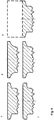
- FIG. 4 A schematic representation of the preferred variation of the foot width B S shows Figure 4 . It becomes clear how the increasing foot width B s results in a strengthening of the rivet foot 40. It can also be seen that an increase in the foot width B s leads to a reduction in the receiving volume of the shaft cavity 50.
- the preferred lower limit of the specified larger range for the rivet foot width B S ensures that the rivet foot 40 only spreads out after the top layer or a first component has penetrated a stack of components. This ensures a larger undercut in the punch rivet connection, which supports the connection of the components.
- the preferred inlet radius R S is defined as a multiple of the foot width B s , in particular according to R S ⁇ 20 B S. Furthermore, the inlet radius R s preferably has a size of 0.3 mm R R s 6 6 mm and in particular 1 mm R R S 4 4 mm. A preferred variation of the inlet radius R S shows schematically Figure 2 .
- the convex inlet area 52 in the preferred radius area enables the rivet foot 40 to expand smoothly during a joining process.
- the fluid widening of the rivet foot 40 is preferably also associated with a fluid ascent of a punching slug into the shaft cavity 50. This is particularly advantageous if ductile material, such as aluminum, is combined as a cover layer with a hard steel as a second layer or as a middle layer in a component stack and in a punch rivet connection provided therein (see Figures 8 and 9 ).
- the inlet area 52 has too little curvature.
- the inlet area 52 has an approximately rectilinear course, so that the effect of the flowing expansion is lost.
- the infeed radius R s is chosen too small with less than 0.3 mm in accordance with the lower limit, a sharp-edged infeed area prevents it from expanding and shrinking smoothly (see above). It is therefore further preferred according to the invention to provide the inlet radius R S in a range of 1 mm ⁇ R S 4 4 mm.
- the convex inlet area 52 merges tangentially into the straight-line continuation area 54.
- the continuation area 54 is designed similar to an outer surface of a truncated cone, which preferably adjoins the inlet area 52 continuously.
- the straight-line continuation region 54 is preferably at an acute angle ⁇ (see Figure 1 ) arranged with respect to the cylindrical outer surface 32 of the rivet shaft 30. According to different preferred embodiments of the present invention, the continuation area 54 is at an angle a in the range of 5 ° ⁇ 30 °, preferably 5 ° ⁇ 20 °.
- the acute angle ⁇ of the continuation area 54 has an influence on the rigidity of the rivet foot 40 and the associated undercut formation in a joint connection.
- An angle ⁇ > 30 ° thus prevents the rivet foot 40 from spreading sufficiently.
- the shaft cavity 50 would be reduced too much by this large angle for a punching slug holder.
- the shaft cavity 50 has a depth t B.
- the depth t B is defined as the distance between the rivet foot end face 42 and a point of an arch section 56 which is closest to the rivet head 10.
- the depth t B in a range of 1/3 ⁇ t D A B D ⁇ 2/3 a.
- the depth t B determines the size of the receiving volume for a punching slug in the shaft cavity 50. Therefore, according to a preferred embodiment, the depth t B is chosen as large as possible. In this context, it should be noted that with increasing depth t B of the shaft cavity 50, the rigidity of the semi-hollow punch rivet 1 in the foot region 40 also decreases.
- the preferred range specified above is selected such that at least sheet metal thicknesses of up to 1.2 mm can be accommodated in the shaft cavity 50 as a punching slug.
- FIG 7 the preferred embodiment of the semi-hollow punch rivet 1 is shown with a through opening 60.
- the through opening 60 connects the shaft cavity 50 to the top of the rivet head 10.
- Figure 10 shows a flow diagram of a connection method of at least two components using the semi-hollow punch rivet 1 described above.
- a first step S1 the at least two components B1, B2 are arranged one above the other in a stacked arrangement on a die or an anvil.
- the semi-hollow punch rivet 1 is placed in the component stack in order to connect the components B1, B2 to one another.
- the semi-hollow punch rivet 1 connects the two components B1 and B2.
- three components B1, B2, B3 of a component stack are connected to one another via the semi-hollow punch rivet 1.
- a closing head has preferably formed over the rivet head 10.
Landscapes
- Engineering & Computer Science (AREA)
- General Engineering & Computer Science (AREA)
- Mechanical Engineering (AREA)
- Insertion Pins And Rivets (AREA)
- Connection Of Plates (AREA)
Applications Claiming Priority (1)
| Application Number | Priority Date | Filing Date | Title |
|---|---|---|---|
| DE102019102383.1A DE102019102383A1 (de) | 2019-01-30 | 2019-01-30 | Halbhohlstanzniet, eine Stanznietverbindung aus mindestens zwei Bauteilen mithilfe des Halbhohlstanzniets sowie ein Verfahren zum Verbinden der Bauteile mit dem Halbhohlstanzniet |
Publications (3)
| Publication Number | Publication Date |
|---|---|
| EP3690260A1 true EP3690260A1 (fr) | 2020-08-05 |
| EP3690260B1 EP3690260B1 (fr) | 2021-05-26 |
| EP3690260B8 EP3690260B8 (fr) | 2021-07-28 |
Family
ID=69326441
Family Applications (1)
| Application Number | Title | Priority Date | Filing Date |
|---|---|---|---|
| EP20153901.2A Active EP3690260B8 (fr) | 2019-01-30 | 2020-01-27 | Rivet auto-poinçonneur semi-tubulaire, raccordement riveté d'au moins deux composants à l'aide du rivet auto-poinçonneur semi-tubulaire ainsi que procédé de raccordement des composants au rivet auto-poinçonneur semi-tubulaire |
Country Status (8)
| Country | Link |
|---|---|
| US (1) | US11686336B2 (fr) |
| EP (1) | EP3690260B8 (fr) |
| JP (1) | JP6909321B2 (fr) |
| KR (1) | KR102297922B1 (fr) |
| CN (1) | CN111271357B (fr) |
| DE (1) | DE102019102383A1 (fr) |
| ES (1) | ES2884823T3 (fr) |
| HU (1) | HUE055333T2 (fr) |
Cited By (2)
| Publication number | Priority date | Publication date | Assignee | Title |
|---|---|---|---|---|
| EP3952024A1 (fr) * | 2020-08-06 | 2022-02-09 | Lisa Dräxlmaier GmbH | Barre omnibus pour un véhicule automobile et procédé de fabrication d'une barre omnibus |
| DE102022128989A1 (de) | 2022-11-02 | 2024-05-02 | Te Connectivity Germany Gmbh | Verbindungsanordnung und verfahren zur herstellung einer verbindungsanordnung |
Families Citing this family (5)
| Publication number | Priority date | Publication date | Assignee | Title |
|---|---|---|---|---|
| DE102020102982A1 (de) | 2020-02-05 | 2021-08-05 | Böllhoff Verbindungstechnik GmbH | Fügeelement, Verbindungsstruktur mit dem Fügeelement, Herstellungsverfahren des Fügeelements und entsprechendes Verbindungsverfahren |
| DE102021103913A1 (de) | 2021-02-18 | 2022-08-18 | Böllhoff Verbindungstechnik GmbH | Hohlstanzniet sowie Fügeverbindung mit dem Hohlstanzniet |
| DE102021107789B4 (de) | 2021-03-29 | 2023-12-07 | Audi Aktiengesellschaft | Stanznietverbindung und Verfahren zur Herstellung einer Stanznietverbindung |
| DE102021112715A1 (de) | 2021-05-17 | 2022-11-17 | Böllhoff Verbindungstechnik GmbH | Halbhohlstanzniet, eine Stanznietverbindung aus mindestens zwei Bauteilen mithilfe des Halbhohlstanzniets sowie ein Verfahren zum Verbinden der Bauteile mit dem Halbhohlstanzniet und ein Herstellungsverfahren des Halbhohlstanzniets |
| DE102021112716A1 (de) | 2021-05-17 | 2022-11-17 | Böllhoff Verbindungstechnik GmbH | Halbhohlstanzniet, eine Stanznietverbindung aus mindestens zwei Bauteilen mithilfe des Halbhohlstanzniets, ein Herstellungsverfahren des Halbhohlstanzniets sowie ein Verfahren zum Verbinden der Bauteile mit dem Halbhohlstanzniet |
Citations (9)
| Publication number | Priority date | Publication date | Assignee | Title |
|---|---|---|---|---|
| GB2141369A (en) * | 1983-06-15 | 1984-12-19 | Bl Tech Ltd | Rivetting |
| DE19927103A1 (de) * | 1999-06-14 | 2000-12-21 | Univ Dresden Tech | Verfahren, Vorrichtung sowie Hilfsfügeteil zum mechanischen Fügen |
| EP0833063B1 (fr) | 1996-09-11 | 2002-07-31 | Richard Bergner GmbH & Co | Rivet poinçonnant |
| EP1229254B1 (fr) | 2001-02-02 | 2005-01-19 | Richard Bergner Verbindungstechnik GmbH & Co KG | Liaison par rivetage poinçonnant et rivet poinçonnant creux |
| DE102005020416B4 (de) | 2005-05-03 | 2007-08-16 | Richard Bergner Verbindungstechnik Gmbh & Co. Kg | Halbhohlstanzniet sowie Stanznietverbindung |
| DE102009050342B4 (de) | 2009-10-22 | 2011-10-13 | Audi Ag | Halbhohlstanzniet |
| EP2024651B2 (fr) | 2006-05-13 | 2014-03-05 | Henrob Limited | Rivetage a percage automatique |
| DE102013020504A1 (de) | 2013-12-11 | 2015-06-11 | Newfrey Llc | Stanzniet sowie Stanznietverfahren und -verbindung |
| DE102014201976A1 (de) * | 2014-02-04 | 2015-08-06 | Böllhoff Verbindungstechnik GmbH | Stanzniet |
Family Cites Families (18)
| Publication number | Priority date | Publication date | Assignee | Title |
|---|---|---|---|---|
| US216719A (en) * | 1879-06-24 | Improvement in rivets | ||
| US203815A (en) * | 1878-05-21 | Improvement in rivets | ||
| US4221041A (en) * | 1978-10-02 | 1980-09-09 | Boeing Commercial Airplane Company | Semi-tubular rivets and method of using |
| JP2958272B2 (ja) * | 1996-05-29 | 1999-10-06 | 福井鋲螺株式会社 | 打込リベット |
| DE19728736A1 (de) * | 1997-07-04 | 1999-01-07 | Rivet Technology P Ltd | Verfahren zum Herstellen von Befestigungselementen |
| US6325584B1 (en) * | 1999-03-30 | 2001-12-04 | Richard Bergner Gmbh | Self-piercing rivet |
| JP2003106316A (ja) | 2001-09-28 | 2003-04-09 | Fukui Byora Co Ltd | 自己穿孔型リベット及び自己穿孔型リベットの結合状態の良否検査装置並びにこの装置を備えたリベットセッタ |
| JP2004060855A (ja) | 2002-07-31 | 2004-02-26 | Nippon Pop Rivets & Fasteners Ltd | セルフピアシングリベット |
| JP2004076854A (ja) | 2002-08-19 | 2004-03-11 | Fukui Byora Co Ltd | 自己穿孔型リベット構造 |
| JP4566669B2 (ja) | 2004-09-21 | 2010-10-20 | 日本碍子株式会社 | 気泡噴射装置 |
| DE202005012677U1 (de) * | 2005-08-09 | 2005-10-13 | Textron Verbindungstechnik Gmbh & Co. Ohg | Selbststanzendes rotationsymmetrisches Niet |
| DE102006028537B3 (de) * | 2006-06-21 | 2007-05-10 | Singh, Sumanjit, Dr. | Stanzniet und Matrize |
| DE102009039936A1 (de) | 2009-08-24 | 2011-04-07 | Newfrey Llc, Newark | Stanzniet, Verfahren zum Hersteller einer Stanznietverbindung und Werkstückanordnung |
| DE102009048398A1 (de) | 2009-10-06 | 2011-04-07 | Böllhoff Verbindungstechnik GmbH | Verbindung zwischen zwei Bauteilen aus verstärktem Kunststoff und Verfahren zu ihrer Herstellung |
| FR2972121A1 (fr) * | 2011-03-04 | 2012-09-07 | Eris | Procede de pose d'un rivet a ame creuse, rivet et outil de pose adaptes |
| JP2016055291A (ja) * | 2013-06-03 | 2016-04-21 | ポップリベット・ファスナー株式会社 | 樹脂部材の接合装置、接合構造及び接合方法 |
| CN108555219B (zh) | 2018-05-14 | 2019-12-31 | 上海应用技术大学 | 一种半空心铆钉的自冲铆接装置及自冲铆方法 |
| JP7182989B2 (ja) * | 2018-10-12 | 2022-12-05 | 株式会社アーレスティ | 接合体の製造方法および板状部材の品質管理方法 |
-
2019
- 2019-01-30 DE DE102019102383.1A patent/DE102019102383A1/de active Pending
-
2020
- 2020-01-21 CN CN202010071166.8A patent/CN111271357B/zh active Active
- 2020-01-21 US US16/748,135 patent/US11686336B2/en active Active
- 2020-01-24 JP JP2020009991A patent/JP6909321B2/ja active Active
- 2020-01-27 HU HUE20153901A patent/HUE055333T2/hu unknown
- 2020-01-27 EP EP20153901.2A patent/EP3690260B8/fr active Active
- 2020-01-27 ES ES20153901T patent/ES2884823T3/es active Active
- 2020-01-29 KR KR1020200010509A patent/KR102297922B1/ko active IP Right Grant
Patent Citations (9)
| Publication number | Priority date | Publication date | Assignee | Title |
|---|---|---|---|---|
| GB2141369A (en) * | 1983-06-15 | 1984-12-19 | Bl Tech Ltd | Rivetting |
| EP0833063B1 (fr) | 1996-09-11 | 2002-07-31 | Richard Bergner GmbH & Co | Rivet poinçonnant |
| DE19927103A1 (de) * | 1999-06-14 | 2000-12-21 | Univ Dresden Tech | Verfahren, Vorrichtung sowie Hilfsfügeteil zum mechanischen Fügen |
| EP1229254B1 (fr) | 2001-02-02 | 2005-01-19 | Richard Bergner Verbindungstechnik GmbH & Co KG | Liaison par rivetage poinçonnant et rivet poinçonnant creux |
| DE102005020416B4 (de) | 2005-05-03 | 2007-08-16 | Richard Bergner Verbindungstechnik Gmbh & Co. Kg | Halbhohlstanzniet sowie Stanznietverbindung |
| EP2024651B2 (fr) | 2006-05-13 | 2014-03-05 | Henrob Limited | Rivetage a percage automatique |
| DE102009050342B4 (de) | 2009-10-22 | 2011-10-13 | Audi Ag | Halbhohlstanzniet |
| DE102013020504A1 (de) | 2013-12-11 | 2015-06-11 | Newfrey Llc | Stanzniet sowie Stanznietverfahren und -verbindung |
| DE102014201976A1 (de) * | 2014-02-04 | 2015-08-06 | Böllhoff Verbindungstechnik GmbH | Stanzniet |
Cited By (2)
| Publication number | Priority date | Publication date | Assignee | Title |
|---|---|---|---|---|
| EP3952024A1 (fr) * | 2020-08-06 | 2022-02-09 | Lisa Dräxlmaier GmbH | Barre omnibus pour un véhicule automobile et procédé de fabrication d'une barre omnibus |
| DE102022128989A1 (de) | 2022-11-02 | 2024-05-02 | Te Connectivity Germany Gmbh | Verbindungsanordnung und verfahren zur herstellung einer verbindungsanordnung |
Also Published As
| Publication number | Publication date |
|---|---|
| KR102297922B1 (ko) | 2021-09-02 |
| CN111271357A (zh) | 2020-06-12 |
| JP2020122573A (ja) | 2020-08-13 |
| EP3690260B8 (fr) | 2021-07-28 |
| US20200240452A1 (en) | 2020-07-30 |
| CN111271357B (zh) | 2022-04-01 |
| JP6909321B2 (ja) | 2021-07-28 |
| US11686336B2 (en) | 2023-06-27 |
| ES2884823T3 (es) | 2021-12-13 |
| EP3690260B1 (fr) | 2021-05-26 |
| DE102019102383A1 (de) | 2020-07-30 |
| KR20200094690A (ko) | 2020-08-07 |
| HUE055333T2 (hu) | 2021-11-29 |
Similar Documents
| Publication | Publication Date | Title |
|---|---|---|
| EP3690260B1 (fr) | Rivet auto-poinçonneur semi-tubulaire, raccordement riveté d'au moins deux composants à l'aide du rivet auto-poinçonneur semi-tubulaire ainsi que procédé de raccordement des composants au rivet auto-poinçonneur semi-tubulaire | |
| EP1918596B1 (fr) | Rivet aveugle et son utilisation | |
| EP1886030B1 (fr) | Rivet | |
| DE102005048863B4 (de) | Nietverbindung | |
| DE102012215901A1 (de) | Loch- und gewindeformende Schraube zum Direktverschrauben von Bauteilen ohne Vorlochen, sowie hiermit hergestellter Bauteilverbund | |
| EP0678679A1 (fr) | Elément à montage par rivetage dans une pièce en tôle | |
| WO2007147551A1 (fr) | Rivet auto-poinçonneur et matrice | |
| EP1705385A1 (fr) | Passage et procédé de fabrication | |
| EP3371467B1 (fr) | Rivet de poinçonnage semi-cylindrique pour liaison de tôles minces, procédé de fabrication et procédé de réalisation d'une liaison | |
| DE102016204619A1 (de) | Einpressverbindung zwischen einem hochfesten Bauteil und einem Einpresselement, Verfahren zur Ausbildung einer solchen Einpressverbindung sowie Einpresselement für eine solche Einpressverbindung | |
| EP1229254A2 (fr) | Liaison par rivetage poinçonnant et rivet poinçonnant creux | |
| WO2009024311A2 (fr) | Rivet aveugle | |
| EP1064466B1 (fr) | Rivet a estamper | |
| DE102013215291A1 (de) | Gewindebuchse zum Einschrauben | |
| DE102017115529A1 (de) | Schweißhilfsfügeteil | |
| WO1982002579A1 (fr) | Ecrou encastrable | |
| EP3366384B1 (fr) | Methode de fabrication d'un rivet aveugle, rivet aveugle et assemblage de fixation | |
| DE202017105715U1 (de) | Einpressverbindung zwischen einem hochfesten Bauteil und einem Einpresselement sowie Einpresselement für eine solche Einpressverbindung | |
| DE202019005800U1 (de) | Zweiteilige hochfeste Schraube | |
| EP0535193B1 (fr) | Procede pour la fabrication d'une section de tige cylindrique non filetee d'une extremite de fixation ou d'une partie d'extremite de fixation | |
| DE102019102380A1 (de) | Vollstanzniet, eine Stanznietverbindung aus mindestens zwei Bauteilen mithilfe des Vollstanzniets sowie ein Verfahren zum Verbinden der Bauteile mit dem Vollstanzniet | |
| EP2558733B1 (fr) | Dispositif d'expansion, assemblage et système | |
| EP2822759B1 (fr) | Tôle légère et construction comprenant une tôle légère | |
| EP1181461A1 (fr) | Rivet aveugle pour pieces a parois de differentes epaisseurs et procede de fabrication dudit rivet | |
| EP2042251B1 (fr) | Procédé de fabrication d'un boulon à bague d'arrêt et boulon à bague d'arrêt |
Legal Events
| Date | Code | Title | Description |
|---|---|---|---|
| PUAI | Public reference made under article 153(3) epc to a published international application that has entered the european phase |
Free format text: ORIGINAL CODE: 0009012 |
|
| STAA | Information on the status of an ep patent application or granted ep patent |
Free format text: STATUS: THE APPLICATION HAS BEEN PUBLISHED |
|
| AK | Designated contracting states |
Kind code of ref document: A1 Designated state(s): AL AT BE BG CH CY CZ DE DK EE ES FI FR GB GR HR HU IE IS IT LI LT LU LV MC MK MT NL NO PL PT RO RS SE SI SK SM TR |
|
| AX | Request for extension of the european patent |
Extension state: BA ME |
|
| STAA | Information on the status of an ep patent application or granted ep patent |
Free format text: STATUS: REQUEST FOR EXAMINATION WAS MADE |
|
| 17P | Request for examination filed |
Effective date: 20200907 |
|
| RBV | Designated contracting states (corrected) |
Designated state(s): AL AT BE BG CH CY CZ DE DK EE ES FI FR GB GR HR HU IE IS IT LI LT LU LV MC MK MT NL NO PL PT RO RS SE SI SK SM TR |
|
| RIC1 | Information provided on ipc code assigned before grant |
Ipc: F16B 19/08 20060101AFI20210115BHEP |
|
| GRAP | Despatch of communication of intention to grant a patent |
Free format text: ORIGINAL CODE: EPIDOSNIGR1 |
|
| STAA | Information on the status of an ep patent application or granted ep patent |
Free format text: STATUS: GRANT OF PATENT IS INTENDED |
|
| INTG | Intention to grant announced |
Effective date: 20210226 |
|
| GRAS | Grant fee paid |
Free format text: ORIGINAL CODE: EPIDOSNIGR3 |
|
| GRAA | (expected) grant |
Free format text: ORIGINAL CODE: 0009210 |
|
| STAA | Information on the status of an ep patent application or granted ep patent |
Free format text: STATUS: THE PATENT HAS BEEN GRANTED |
|
| RIN1 | Information on inventor provided before grant (corrected) |
Inventor name: HENKE, DENNIS Inventor name: MENNE, FRANZ FERDINAND Inventor name: DIE WEITEREN ERFINDER HABEN AUF IHR RECHT VERZICHTET, ALS SOLCHE BEKANNT GEMACHT ZU WERDEN. |
|
| AK | Designated contracting states |
Kind code of ref document: B1 Designated state(s): AL AT BE BG CH CY CZ DE DK EE ES FI FR GB GR HR HU IE IS IT LI LT LU LV MC MK MT NL NO PL PT RO RS SE SI SK SM TR |
|
| REG | Reference to a national code |
Ref country code: GB Ref legal event code: FG4D Free format text: NOT ENGLISH |
|
| REG | Reference to a national code |
Ref country code: CH Ref legal event code: EP |
|
| REG | Reference to a national code |
Ref country code: DE Ref legal event code: R096 Ref document number: 502020000042 Country of ref document: DE |
|
| REG | Reference to a national code |
Ref country code: AT Ref legal event code: REF Ref document number: 1396507 Country of ref document: AT Kind code of ref document: T Effective date: 20210615 |
|
| GRAT | Correction requested after decision to grant or after decision to maintain patent in amended form |
Free format text: ORIGINAL CODE: EPIDOSNCDEC |
|
| REG | Reference to a national code |
Ref country code: IE Ref legal event code: FG4D Free format text: LANGUAGE OF EP DOCUMENT: GERMAN |
|
| REG | Reference to a national code |
Ref country code: CH Ref legal event code: PK Free format text: BERICHTIGUNGEN |
|
| RIN2 | Information on inventor provided after grant (corrected) |
Inventor name: ERBIS, SERGEJ Inventor name: HENKE, DENNIS Inventor name: MENNE, FRANZ FERDINAND |
|
| REG | Reference to a national code |
Ref country code: LT Ref legal event code: MG9D |
|
| REG | Reference to a national code |
Ref country code: SK Ref legal event code: T3 Ref document number: E 37963 Country of ref document: SK |
|
| PG25 | Lapsed in a contracting state [announced via postgrant information from national office to epo] |
Ref country code: FI Free format text: LAPSE BECAUSE OF FAILURE TO SUBMIT A TRANSLATION OF THE DESCRIPTION OR TO PAY THE FEE WITHIN THE PRESCRIBED TIME-LIMIT Effective date: 20210526 Ref country code: HR Free format text: LAPSE BECAUSE OF FAILURE TO SUBMIT A TRANSLATION OF THE DESCRIPTION OR TO PAY THE FEE WITHIN THE PRESCRIBED TIME-LIMIT Effective date: 20210526 Ref country code: LT Free format text: LAPSE BECAUSE OF FAILURE TO SUBMIT A TRANSLATION OF THE DESCRIPTION OR TO PAY THE FEE WITHIN THE PRESCRIBED TIME-LIMIT Effective date: 20210526 Ref country code: BG Free format text: LAPSE BECAUSE OF FAILURE TO SUBMIT A TRANSLATION OF THE DESCRIPTION OR TO PAY THE FEE WITHIN THE PRESCRIBED TIME-LIMIT Effective date: 20210826 |
|
| REG | Reference to a national code |
Ref country code: NL Ref legal event code: MP Effective date: 20210526 |
|
| REG | Reference to a national code |
Ref country code: HU Ref legal event code: AG4A Ref document number: E055333 Country of ref document: HU |
|
| PG25 | Lapsed in a contracting state [announced via postgrant information from national office to epo] |
Ref country code: IS Free format text: LAPSE BECAUSE OF FAILURE TO SUBMIT A TRANSLATION OF THE DESCRIPTION OR TO PAY THE FEE WITHIN THE PRESCRIBED TIME-LIMIT Effective date: 20210926 Ref country code: SE Free format text: LAPSE BECAUSE OF FAILURE TO SUBMIT A TRANSLATION OF THE DESCRIPTION OR TO PAY THE FEE WITHIN THE PRESCRIBED TIME-LIMIT Effective date: 20210526 Ref country code: PT Free format text: LAPSE BECAUSE OF FAILURE TO SUBMIT A TRANSLATION OF THE DESCRIPTION OR TO PAY THE FEE WITHIN THE PRESCRIBED TIME-LIMIT Effective date: 20210927 Ref country code: RS Free format text: LAPSE BECAUSE OF FAILURE TO SUBMIT A TRANSLATION OF THE DESCRIPTION OR TO PAY THE FEE WITHIN THE PRESCRIBED TIME-LIMIT Effective date: 20210526 Ref country code: PL Free format text: LAPSE BECAUSE OF FAILURE TO SUBMIT A TRANSLATION OF THE DESCRIPTION OR TO PAY THE FEE WITHIN THE PRESCRIBED TIME-LIMIT Effective date: 20210526 Ref country code: NO Free format text: LAPSE BECAUSE OF FAILURE TO SUBMIT A TRANSLATION OF THE DESCRIPTION OR TO PAY THE FEE WITHIN THE PRESCRIBED TIME-LIMIT Effective date: 20210826 Ref country code: LV Free format text: LAPSE BECAUSE OF FAILURE TO SUBMIT A TRANSLATION OF THE DESCRIPTION OR TO PAY THE FEE WITHIN THE PRESCRIBED TIME-LIMIT Effective date: 20210526 |
|
| REG | Reference to a national code |
Ref country code: ES Ref legal event code: FG2A Ref document number: 2884823 Country of ref document: ES Kind code of ref document: T3 Effective date: 20211213 |
|
| PG25 | Lapsed in a contracting state [announced via postgrant information from national office to epo] |
Ref country code: NL Free format text: LAPSE BECAUSE OF FAILURE TO SUBMIT A TRANSLATION OF THE DESCRIPTION OR TO PAY THE FEE WITHIN THE PRESCRIBED TIME-LIMIT Effective date: 20210526 |
|
| PG25 | Lapsed in a contracting state [announced via postgrant information from national office to epo] |
Ref country code: EE Free format text: LAPSE BECAUSE OF FAILURE TO SUBMIT A TRANSLATION OF THE DESCRIPTION OR TO PAY THE FEE WITHIN THE PRESCRIBED TIME-LIMIT Effective date: 20210526 Ref country code: DK Free format text: LAPSE BECAUSE OF FAILURE TO SUBMIT A TRANSLATION OF THE DESCRIPTION OR TO PAY THE FEE WITHIN THE PRESCRIBED TIME-LIMIT Effective date: 20210526 Ref country code: CZ Free format text: LAPSE BECAUSE OF FAILURE TO SUBMIT A TRANSLATION OF THE DESCRIPTION OR TO PAY THE FEE WITHIN THE PRESCRIBED TIME-LIMIT Effective date: 20210526 Ref country code: RO Free format text: LAPSE BECAUSE OF FAILURE TO SUBMIT A TRANSLATION OF THE DESCRIPTION OR TO PAY THE FEE WITHIN THE PRESCRIBED TIME-LIMIT Effective date: 20210526 Ref country code: SM Free format text: LAPSE BECAUSE OF FAILURE TO SUBMIT A TRANSLATION OF THE DESCRIPTION OR TO PAY THE FEE WITHIN THE PRESCRIBED TIME-LIMIT Effective date: 20210526 |
|
| REG | Reference to a national code |
Ref country code: DE Ref legal event code: R097 Ref document number: 502020000042 Country of ref document: DE |
|
| PLBE | No opposition filed within time limit |
Free format text: ORIGINAL CODE: 0009261 |
|
| STAA | Information on the status of an ep patent application or granted ep patent |
Free format text: STATUS: NO OPPOSITION FILED WITHIN TIME LIMIT |
|
| 26N | No opposition filed |
Effective date: 20220301 |
|
| PG25 | Lapsed in a contracting state [announced via postgrant information from national office to epo] |
Ref country code: IS Free format text: LAPSE BECAUSE OF FAILURE TO SUBMIT A TRANSLATION OF THE DESCRIPTION OR TO PAY THE FEE WITHIN THE PRESCRIBED TIME-LIMIT Effective date: 20210926 Ref country code: AL Free format text: LAPSE BECAUSE OF FAILURE TO SUBMIT A TRANSLATION OF THE DESCRIPTION OR TO PAY THE FEE WITHIN THE PRESCRIBED TIME-LIMIT Effective date: 20210526 |
|
| PG25 | Lapsed in a contracting state [announced via postgrant information from national office to epo] |
Ref country code: MC Free format text: LAPSE BECAUSE OF FAILURE TO SUBMIT A TRANSLATION OF THE DESCRIPTION OR TO PAY THE FEE WITHIN THE PRESCRIBED TIME-LIMIT Effective date: 20210526 |
|
| REG | Reference to a national code |
Ref country code: BE Ref legal event code: MM Effective date: 20220131 |
|
| PG25 | Lapsed in a contracting state [announced via postgrant information from national office to epo] |
Ref country code: LU Free format text: LAPSE BECAUSE OF NON-PAYMENT OF DUE FEES Effective date: 20220127 |
|
| PG25 | Lapsed in a contracting state [announced via postgrant information from national office to epo] |
Ref country code: BE Free format text: LAPSE BECAUSE OF NON-PAYMENT OF DUE FEES Effective date: 20220131 |
|
| PG25 | Lapsed in a contracting state [announced via postgrant information from national office to epo] |
Ref country code: IE Free format text: LAPSE BECAUSE OF NON-PAYMENT OF DUE FEES Effective date: 20220127 |
|
| PGFP | Annual fee paid to national office [announced via postgrant information from national office to epo] |
Ref country code: FR Payment date: 20230123 Year of fee payment: 4 |
|
| PGFP | Annual fee paid to national office [announced via postgrant information from national office to epo] |
Ref country code: IT Payment date: 20230131 Year of fee payment: 4 |
|
| REG | Reference to a national code |
Ref country code: CH Ref legal event code: PL |
|
| PG25 | Lapsed in a contracting state [announced via postgrant information from national office to epo] |
Ref country code: LI Free format text: LAPSE BECAUSE OF NON-PAYMENT OF DUE FEES Effective date: 20230131 Ref country code: CH Free format text: LAPSE BECAUSE OF NON-PAYMENT OF DUE FEES Effective date: 20230131 |
|
| PGFP | Annual fee paid to national office [announced via postgrant information from national office to epo] |
Ref country code: ES Payment date: 20240216 Year of fee payment: 5 |
|
| PG25 | Lapsed in a contracting state [announced via postgrant information from national office to epo] |
Ref country code: MK Free format text: LAPSE BECAUSE OF FAILURE TO SUBMIT A TRANSLATION OF THE DESCRIPTION OR TO PAY THE FEE WITHIN THE PRESCRIBED TIME-LIMIT Effective date: 20210526 Ref country code: CY Free format text: LAPSE BECAUSE OF FAILURE TO SUBMIT A TRANSLATION OF THE DESCRIPTION OR TO PAY THE FEE WITHIN THE PRESCRIBED TIME-LIMIT Effective date: 20210526 |
|
| PGFP | Annual fee paid to national office [announced via postgrant information from national office to epo] |
Ref country code: DE Payment date: 20240327 Year of fee payment: 5 Ref country code: HU Payment date: 20240125 Year of fee payment: 5 Ref country code: GB Payment date: 20240124 Year of fee payment: 5 Ref country code: SK Payment date: 20240122 Year of fee payment: 5 |