EP3690260A1 - Semi-hollow rivet, a punch rivet connection comprising at least two components with the aid of the semi-hollow rivet and a method for connecting the components with the semi-hollow rivet - Google Patents
Semi-hollow rivet, a punch rivet connection comprising at least two components with the aid of the semi-hollow rivet and a method for connecting the components with the semi-hollow rivet Download PDFInfo
- Publication number
- EP3690260A1 EP3690260A1 EP20153901.2A EP20153901A EP3690260A1 EP 3690260 A1 EP3690260 A1 EP 3690260A1 EP 20153901 A EP20153901 A EP 20153901A EP 3690260 A1 EP3690260 A1 EP 3690260A1
- Authority
- EP
- European Patent Office
- Prior art keywords
- rivet
- semi
- shaft
- hollow punch
- foot
- Prior art date
- Legal status (The legal status is an assumption and is not a legal conclusion. Google has not performed a legal analysis and makes no representation as to the accuracy of the status listed.)
- Granted
Links
- 238000000034 method Methods 0.000 title claims description 10
- 230000001154 acute effect Effects 0.000 claims abstract description 10
- 238000004080 punching Methods 0.000 description 33
- 239000000463 material Substances 0.000 description 12
- 238000005304 joining Methods 0.000 description 10
- 229910000831 Steel Inorganic materials 0.000 description 9
- 239000010959 steel Substances 0.000 description 9
- 229910052751 metal Inorganic materials 0.000 description 7
- 239000002184 metal Substances 0.000 description 7
- 238000013461 design Methods 0.000 description 5
- 229910052782 aluminium Inorganic materials 0.000 description 3
- XAGFODPZIPBFFR-UHFFFAOYSA-N aluminium Chemical compound [Al] XAGFODPZIPBFFR-UHFFFAOYSA-N 0.000 description 3
- 230000008859 change Effects 0.000 description 3
- 230000000694 effects Effects 0.000 description 3
- 230000008569 process Effects 0.000 description 3
- 239000007787 solid Substances 0.000 description 3
- CURLTUGMZLYLDI-UHFFFAOYSA-N Carbon dioxide Chemical compound O=C=O CURLTUGMZLYLDI-UHFFFAOYSA-N 0.000 description 2
- TZCXTZWJZNENPQ-UHFFFAOYSA-L barium sulfate Chemical compound [Ba+2].[O-]S([O-])(=O)=O TZCXTZWJZNENPQ-UHFFFAOYSA-L 0.000 description 2
- 230000005540 biological transmission Effects 0.000 description 2
- 230000015572 biosynthetic process Effects 0.000 description 2
- 238000010276 construction Methods 0.000 description 2
- 238000010586 diagram Methods 0.000 description 2
- 239000012530 fluid Substances 0.000 description 2
- 150000002739 metals Chemical class 0.000 description 2
- 230000035515 penetration Effects 0.000 description 2
- 238000000926 separation method Methods 0.000 description 2
- 238000003892 spreading Methods 0.000 description 2
- 230000007480 spreading Effects 0.000 description 2
- 229910000838 Al alloy Inorganic materials 0.000 description 1
- RYGMFSIKBFXOCR-UHFFFAOYSA-N Copper Chemical compound [Cu] RYGMFSIKBFXOCR-UHFFFAOYSA-N 0.000 description 1
- 238000010521 absorption reaction Methods 0.000 description 1
- 230000001174 ascending effect Effects 0.000 description 1
- 229910002092 carbon dioxide Inorganic materials 0.000 description 1
- 239000001569 carbon dioxide Substances 0.000 description 1
- 229910052802 copper Inorganic materials 0.000 description 1
- 239000010949 copper Substances 0.000 description 1
- 230000007423 decrease Effects 0.000 description 1
- 238000011161 development Methods 0.000 description 1
- 238000009826 distribution Methods 0.000 description 1
- 238000005516 engineering process Methods 0.000 description 1
- 238000012545 processing Methods 0.000 description 1
- 230000009467 reduction Effects 0.000 description 1
- 210000002023 somite Anatomy 0.000 description 1
- 238000005728 strengthening Methods 0.000 description 1
- 238000012546 transfer Methods 0.000 description 1
- 230000007704 transition Effects 0.000 description 1
- 208000008918 voyeurism Diseases 0.000 description 1
Images


Classifications
-
- F—MECHANICAL ENGINEERING; LIGHTING; HEATING; WEAPONS; BLASTING
- F16—ENGINEERING ELEMENTS AND UNITS; GENERAL MEASURES FOR PRODUCING AND MAINTAINING EFFECTIVE FUNCTIONING OF MACHINES OR INSTALLATIONS; THERMAL INSULATION IN GENERAL
- F16B—DEVICES FOR FASTENING OR SECURING CONSTRUCTIONAL ELEMENTS OR MACHINE PARTS TOGETHER, e.g. NAILS, BOLTS, CIRCLIPS, CLAMPS, CLIPS OR WEDGES; JOINTS OR JOINTING
- F16B19/00—Bolts without screw-thread; Pins, including deformable elements; Rivets
- F16B19/04—Rivets; Spigots or the like fastened by riveting
- F16B19/08—Hollow rivets; Multi-part rivets
- F16B19/086—Self-piercing rivets
-
- B—PERFORMING OPERATIONS; TRANSPORTING
- B21—MECHANICAL METAL-WORKING WITHOUT ESSENTIALLY REMOVING MATERIAL; PUNCHING METAL
- B21J—FORGING; HAMMERING; PRESSING METAL; RIVETING; FORGE FURNACES
- B21J15/00—Riveting
- B21J15/02—Riveting procedures
- B21J15/025—Setting self-piercing rivets
-
- B—PERFORMING OPERATIONS; TRANSPORTING
- B21—MECHANICAL METAL-WORKING WITHOUT ESSENTIALLY REMOVING MATERIAL; PUNCHING METAL
- B21J—FORGING; HAMMERING; PRESSING METAL; RIVETING; FORGE FURNACES
- B21J15/00—Riveting
- B21J15/02—Riveting procedures
- B21J15/04—Riveting hollow rivets mechanically
-
- F—MECHANICAL ENGINEERING; LIGHTING; HEATING; WEAPONS; BLASTING
- F16—ENGINEERING ELEMENTS AND UNITS; GENERAL MEASURES FOR PRODUCING AND MAINTAINING EFFECTIVE FUNCTIONING OF MACHINES OR INSTALLATIONS; THERMAL INSULATION IN GENERAL
- F16B—DEVICES FOR FASTENING OR SECURING CONSTRUCTIONAL ELEMENTS OR MACHINE PARTS TOGETHER, e.g. NAILS, BOLTS, CIRCLIPS, CLAMPS, CLIPS OR WEDGES; JOINTS OR JOINTING
- F16B19/00—Bolts without screw-thread; Pins, including deformable elements; Rivets
- F16B19/04—Rivets; Spigots or the like fastened by riveting
- F16B19/08—Hollow rivets; Multi-part rivets
-
- F—MECHANICAL ENGINEERING; LIGHTING; HEATING; WEAPONS; BLASTING
- F16—ENGINEERING ELEMENTS AND UNITS; GENERAL MEASURES FOR PRODUCING AND MAINTAINING EFFECTIVE FUNCTIONING OF MACHINES OR INSTALLATIONS; THERMAL INSULATION IN GENERAL
- F16B—DEVICES FOR FASTENING OR SECURING CONSTRUCTIONAL ELEMENTS OR MACHINE PARTS TOGETHER, e.g. NAILS, BOLTS, CIRCLIPS, CLAMPS, CLIPS OR WEDGES; JOINTS OR JOINTING
- F16B5/00—Joining sheets or plates, e.g. panels, to one another or to strips or bars parallel to them
- F16B5/04—Joining sheets or plates, e.g. panels, to one another or to strips or bars parallel to them by means of riveting
Definitions
- the present invention relates to a semi-hollow punch rivet with which a connection can be established between at least two stacked components arranged one above the other. Furthermore, the present invention relates to a punch rivet connection composed of at least two components arranged one above the other in a stack and to a method for connecting the at least two components using the semi-hollow punch rivet.
- This punch rivet has a thicker shank wall thickness and a larger shank diameter compared to previously used punch rivet geometries.
- This semi-hollow punch rivet can be used to join Usibor layers up to a maximum sheet thickness of 1.7 mm.
- the enlarged shank diameter increases the punching force or setting force required to insert the semi-hollow punch rivet into the component stack.
- the standard joining systems are not suitable for processing such punch rivets because they are designed for the separation and conveyance of punch rivet elements with a shaft diameter of approx. 5.5 mm. Alternative joining elements are therefore sought, since the semi-hollow punch rivet described above is a special solution.
- EP 0 833 063 B1 describes a semi-hollow punch rivet made of light metal, such as aluminum or an aluminum alloy.
- This semi-hollow punch rivet is used to connect light metal sheets or the like. Since it is not made of steel, a weight-optimized connecting element is used in addition to the use of light metal sheets.
- the use of the semi-hollow punch rivet made of light metal for steel connections or high-strength steels is problematic. Because the semi-hollow punch rivet does not have the appropriate stability for the high joining forces required in this context.
- the semi-hollow punch rivet of the above-mentioned European patent has a conical shaft cavity at the end of the shaft facing away from the head. This shaft cavity is arranged rotationally symmetrically around the longitudinal axis of the rivet shaft. While the blunt rivet foot ensures that the punching slug is separated from the component to be punched, the conical shape of the shaft cavity causes the punching slug to be picked up to tilt. This is due to the pointed inlet of the shaft cavity, which cannot be fully used due to a limited flow of the slug material. This disadvantage has a greater impact when connecting steel components, as is the case in, for example EP 1 229 254 B1 is described.
- the described semi-hollow punch rivet has a shaft cavity which shows a bell-like configuration.
- a convex circular arc runs almost to the bottom of the shaft cavity.
- the convex circular arcs arranged on the sides are connected to one another by a combination of two further circular arcs.
- the use of convexly shaped arcs leads to an even greater tapering of the shaft cavity in the direction of the shaft base.
- the slug gets stuck earlier in the shaft cavity compared to the conical shaft cavity after a successful separation from the first component and hinders the formation of a connection.
- the use of the circular, convex wall design of the semi-hollow punch rivet means that the shaft in the foot area also has a low stability due to the small wall thickness. There is therefore a risk that the punching forces transmitted in the axial direction by the rivet head will not be effectively transmitted to the blunt rivet foot and the rivet shaft will fail.
- the present invention discloses a semi-hollow punch rivet with which a connection between at least two components arranged in a stack one above the other can be produced.
- the semi-hollow punch rivet according to the invention has the following features: a rivet head with a rivet shank extending therefrom, which has a cylindrical outer surface, at an end of the rivet shank facing away from the rivet head there is a blunt rivet foot with a rivet foot end face which is arranged perpendicular to a longitudinal axis of the rivet shank , and a shaft cavity which is bell-shaped in the axial cross section of the rivet shaft extends into the rivet shaft starting at the end of the rivet shaft facing away from the head, the bell-shaped shaft cavity being formed from a convex inlet region which begins on a radial inner side of the rivet foot end face and has an arc shape with an inlet radius Rs runs in the direction of the rivet head, a straight-line continuation area into which the inlet area tangentially merges and which is arranged at an acute angle with respect to the
- the construction of the semi-hollow punch rivet according to the invention realizes an improved transmission of the punching force applied via the rivet head to the joint.
- the punch rivet geometry preferably ensures that the loss of deformation energy within the semi-hollow punch rivet before and / or during penetration of the semi-hollow punch rivet into at least the first component of a punch rivet connection is reduced or completely avoided by deforming the punch rivet.
- the mechanical energy supplied via the rivet head is thus preferably completely available for penetration of the rivet shank into the at least two stacked components arranged one above the other and the associated punching out of a punching slug.
- the shaft cavity arranged rotationally symmetrically with respect to the longitudinal axis of the rivet shank ensures an improved absorption of the punching slug. This is achieved by the combination of the arcuate convex inlet area with a further linear extension area in the direction of the rivet head in the shaft cavity. While, on the one hand, the arched inlet area preferably reduces the occurrence of mechanical stress peaks when producing the punching slug, the linear continuation area preferably provides a reduced tapering of the shaft cavity in the direction of its depth. A volume available for receiving the punching slug in the shaft cavity is thus utilized in such a way that it provides a large receiving volume for the punching slug without losing the stability of the rivet shaft.
- the final vaulted area provided at the base of the shaft cavity is preferably closed or is also designed to be open through a through opening in the direction of the rivet head.
- the preferred opening in the vault area according to the invention provides a further receiving volume for material of the punching slug through a preferred through opening to the rivet head or a blind bore.
- the semi-hollow punch rivet is preferably realized with the shank diameter described above.
- This shaft diameter is adapted to common feed systems as well as punch riveting systems and can be combined with these without extensive design changes to the system technology.
- its rivet end face has a radially extending foot width B s in the range of 1/30 ⁇ D a ⁇ B s ⁇ 1 / 3 ⁇ D, preferably 1/15 D a ⁇ B s ⁇ 1 / 6 D a .
- the semi-hollow punch rivet preferably has a blunt foot geometry.
- the face of the rivet foot extends perpendicularly with respect to the longitudinal axis of the rivet shaft.
- the face of the rivet base also preferably has the radial width specified above in order to be able to optimally transmit the punching force applied via the rivet head to the first component at the joint.
- the preferred size of the face of the rivet base is particularly advantageous for the transmission of high riveting forces when joining high-strength or high-strength steels.
- the semi-hollow punch rivet with the preferred rivet base geometry for establishing a joint connection in a stack of at least three components of the same and / or different materials arranged one above the other.
- Such a joint connection must first ensure that the stability of the semi-hollow punch rivet ensures that sufficiently high mechanical energy is introduced into the joint.
- the shape of the shaft cavity preferably also ensures a sufficient wall thickness of the rivet shaft in the area of the shaft cavity, which is not overloaded by the punching force transmitted from the rivet head to the punching foot.
- the shaft cavity provides a sufficiently large receiving volume for the punching slug available, which is preferably composed of a material of the first and second component when viewed in the joining direction in the case of a connection of at least three components.
- the inlet radius R s has the following size in relation to the foot width Bs: R s 20 20 Bs, preferably 0.3 mm R R s 6 6 mm and in particular 1 mm R Rs 4 4 mm
- the preferably close coordination between the foot width of the blunt rivet foot and the size of the inlet radius is aimed at an optimal functional alignment of the geometry of the semi-hollow punch rivet. Because depending on the components to be connected, the punching force to be applied requires a corresponding size of the foot width. While the entry area into the shaft cavity at the radially inner edge of the foot width must not weaken the rivet shaft of the semi-hollow punch rivet, it can preferably be adjusted at the same time so that a sufficiently large receiving volume in the shaft cavity is available for the punching slug. It is therefore preferred to choose the foot width of the punching foot in close coordination with the size of the inlet radius.
- the continuation area is arranged at an acute angle with respect to the cylindrical outer surface of the rivet shaft.
- This acute angle ⁇ is preferably in the range of 5 ° ⁇ ⁇ 30 30 °, in particular 5 ° ⁇ ⁇ 20 20 ° with respect to the cylindrical outer surface.
- the inlet area which is designed in the form of a circular arc on the basis of the inlet radius Rs, merges directly tangentially into the linear continuation area.
- the continuation area in turn is preferably designed like the lateral surface of a truncated cone. Therefore, this lateral surface or the surface of the continuation area within the shaft cavity has a defined angular orientation with respect to the cylindrical lateral surface of the rivet shaft.
- the preferred range according to the invention of the acute angle ⁇ in the size of 5 ° a a 20 20 ° represents a compromise between the largest possible receiving volume of the shaft cavity and an optimal connection to the curved inlet area.
- a depth t B of the bell-shaped shaft cavity with respect to the shaft diameter D a is in the range of 1/3 D a ⁇ t B ⁇ 2/3 D a provided.
- the depth of the bell-shaped shaft cavity is required customizable. This is preferably set depending on the selected shaft diameter.
- the semi-hollow punch rivet it was recognized that, despite the depth range of the shaft cavity selected above, sufficient stability of the semi-hollow punch rivet is ensured when producing joint connections, depending on the shaft diameter.
- the bell-shaped shaft cavity has a central through opening to the rivet head, which runs in the longitudinal direction of the rivet shaft, or a blind bore in order to form a hollow rivet.
- the present invention also comprises a punch rivet connection composed of at least two stacked components arranged one above the other, which are connected to one another via the semi-hollow punch rivet described above. Due to the preferred variability in the geometry of the semi-hollow punch rivet, it is possible to process different component materials within a joint connection. Accordingly, the semi-hollow punch rivet is preferably used to connect high-strength and high-strength steels of different components. In the same way, it is preferred to use the semi-hollow punch rivet described above for connecting components made of light metals or for connecting components made of light metals and steels.
- the present invention also discloses a method for connecting at least two components using the semi-hollow punch rivet described above.
- This connection method has the following steps: arranging the at least two components one above the other in a stacked arrangement on a die or an anvil and inserting a semi-hollow punch rivet according to one of the preferred embodiments described above into the at least two components.
- Figure 1 shows a schematic sectional view transverse to the longitudinal axis L A of the semi-hollow punch rivet 1.
- the semi-hollow punch rivet 1 comprises a rivet head 10 with a rivet shank 30 extending therefrom.
- the rivet head 10 has a preferred head shape, as exemplified in FIG Figure 6 are shown schematically.
- the rivet shaft 30 is preferably fitted with a countersunk head ( Figure 6A ), a countersunk head with a circular transition to rivet shank 30 ( Figure 6B ) or a flat-round head ( Figure 6C ) combined. It is also preferred to combine the rivet head 10 with a functional element 12, such as preferably a threaded bolt or a nut ( Figure 6D ).
- the rivet shaft 30 has a blunt rivet foot 40 opposite the rivet head 10.
- the rivet foot 40 comprises a rivet foot face 42.
- the rivet foot face 42 is preferably perpendicular to one cylindrical outer surface 32 of the rivet shaft 30 is arranged.
- the rivet foot end face 42 extends perpendicular to the longitudinal axis L A of the semi-hollow punch rivet 1.
- a shaft cavity 50 extends in the direction of the rivet head 10 in the interior of the rivet shaft 30.
- the shaft cavity 50 is arranged rotationally symmetrically about the longitudinal axis L A of the semi-hollow punch rivet 1.
- the shaft cavity 50 has a bell-like shape with an opening adjacent to the rivet 40.
- the shaft cavity 50 in the rivet shaft 30 is preferably shaped such that, in addition to sufficient stability of the rivet foot 40 at high punching forces, there is also a sufficiently large receiving volume for the punching slug in the shaft cavity 50.
- the rivet shank 30 is preferably formed as a solid element starting at the rivet head 10.
- the rivet shaft 30 provided as a solid element extends at least to the middle of the semi-hollow punch rivet 1 with an overall length L. This preferably ensures a large-area distribution of the joining force or the punching force in the area of the semi-hollow punch rivet 1 close to the head. This punching force is first transmitted over the entire cross-sectional area of the rivet shaft 30 in the direction of the rivet foot 40.
- the proportion of the solid element in the rivet shaft 30 is determined by the depth of the shaft cavity 50, as explained in more detail below.
- the rivet shaft 30 is hollow in the foot region.
- the shank cavity 50 extends in a centrally symmetrical arrangement about the longitudinal axis L A in the direction of the rivet head 10.
- a depth t B of the shank cavity 50 is selected such that the semi-hollow punch rivet 1 during the setting process only in the lower half of the rivet shank 30, i.e. in half of the Rivet shank 30 adjacent to the rivet base 40 is formed.
- the geometry of the shaft cavity 50 also ensures that the hollow shaft section is spread open sufficiently to form an undercut in the punch rivet connection produced. This is exemplary in the schematic representations of the punch rivet connections of the Figures 8 and 9 shown.
- the semi-hollow punch rivet 1 has a shank diameter D a of D a 5 5.6 mm.
- the shank diameter D a is preferably 5.5 mm, so that the semi-hollow punch rivet 1 can be processed with common punch rivet and feed systems.
- the rivet head 10 is preferably manufactured with a head diameter D k equal to 7.75 mm. This standard size ensures the use of known joining and rivet feeding systems.
- the rivet length L of the semi-hollow punch rivet 1 is also preferably in a range of 4 mm L L 9 9 mm. Depending on the application, the rivet length L is adapted to the joint to be made or the stack thickness of the components to be connected.
- the semi-hollow punch rivet 1 can preferably be produced from different materials.
- Preferred riveting materials are steel, aluminum or copper. Other materials are also preferred here in order to carry out corresponding joining tasks.
- a convex inlet area 52 begins at the radially inner edge of the rivet foot 40.
- the convex inlet area 52 runs in a circular arc in the direction of the rivet head 10.
- the circular-arc-shaped inlet area 52 has a radius R S , which is defined as a function of a foot width B S of the rivet foot 40.
- the radially extending foot width B S of the rivet foot end face 42 is preferably in the range of 1 / 30D a BB S 11/3 D a , where D A describes the shank diameter discussed above.
- the foot width BS is preferably in the range of 1/15 D a BB S 11/6 D a .
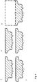
- FIG. 4 A schematic representation of the preferred variation of the foot width B S shows Figure 4 . It becomes clear how the increasing foot width B s results in a strengthening of the rivet foot 40. It can also be seen that an increase in the foot width B s leads to a reduction in the receiving volume of the shaft cavity 50.
- the preferred lower limit of the specified larger range for the rivet foot width B S ensures that the rivet foot 40 only spreads out after the top layer or a first component has penetrated a stack of components. This ensures a larger undercut in the punch rivet connection, which supports the connection of the components.
- the preferred inlet radius R S is defined as a multiple of the foot width B s , in particular according to R S ⁇ 20 B S. Furthermore, the inlet radius R s preferably has a size of 0.3 mm R R s 6 6 mm and in particular 1 mm R R S 4 4 mm. A preferred variation of the inlet radius R S shows schematically Figure 2 .
- the convex inlet area 52 in the preferred radius area enables the rivet foot 40 to expand smoothly during a joining process.
- the fluid widening of the rivet foot 40 is preferably also associated with a fluid ascent of a punching slug into the shaft cavity 50. This is particularly advantageous if ductile material, such as aluminum, is combined as a cover layer with a hard steel as a second layer or as a middle layer in a component stack and in a punch rivet connection provided therein (see Figures 8 and 9 ).
- the inlet area 52 has too little curvature.
- the inlet area 52 has an approximately rectilinear course, so that the effect of the flowing expansion is lost.
- the infeed radius R s is chosen too small with less than 0.3 mm in accordance with the lower limit, a sharp-edged infeed area prevents it from expanding and shrinking smoothly (see above). It is therefore further preferred according to the invention to provide the inlet radius R S in a range of 1 mm ⁇ R S 4 4 mm.
- the convex inlet area 52 merges tangentially into the straight-line continuation area 54.
- the continuation area 54 is designed similar to an outer surface of a truncated cone, which preferably adjoins the inlet area 52 continuously.
- the straight-line continuation region 54 is preferably at an acute angle ⁇ (see Figure 1 ) arranged with respect to the cylindrical outer surface 32 of the rivet shaft 30. According to different preferred embodiments of the present invention, the continuation area 54 is at an angle a in the range of 5 ° ⁇ 30 °, preferably 5 ° ⁇ 20 °.
- the acute angle ⁇ of the continuation area 54 has an influence on the rigidity of the rivet foot 40 and the associated undercut formation in a joint connection.
- An angle ⁇ > 30 ° thus prevents the rivet foot 40 from spreading sufficiently.
- the shaft cavity 50 would be reduced too much by this large angle for a punching slug holder.
- the shaft cavity 50 has a depth t B.
- the depth t B is defined as the distance between the rivet foot end face 42 and a point of an arch section 56 which is closest to the rivet head 10.
- the depth t B in a range of 1/3 ⁇ t D A B D ⁇ 2/3 a.
- the depth t B determines the size of the receiving volume for a punching slug in the shaft cavity 50. Therefore, according to a preferred embodiment, the depth t B is chosen as large as possible. In this context, it should be noted that with increasing depth t B of the shaft cavity 50, the rigidity of the semi-hollow punch rivet 1 in the foot region 40 also decreases.
- the preferred range specified above is selected such that at least sheet metal thicknesses of up to 1.2 mm can be accommodated in the shaft cavity 50 as a punching slug.
- FIG 7 the preferred embodiment of the semi-hollow punch rivet 1 is shown with a through opening 60.
- the through opening 60 connects the shaft cavity 50 to the top of the rivet head 10.
- Figure 10 shows a flow diagram of a connection method of at least two components using the semi-hollow punch rivet 1 described above.
- a first step S1 the at least two components B1, B2 are arranged one above the other in a stacked arrangement on a die or an anvil.
- the semi-hollow punch rivet 1 is placed in the component stack in order to connect the components B1, B2 to one another.
- the semi-hollow punch rivet 1 connects the two components B1 and B2.
- three components B1, B2, B3 of a component stack are connected to one another via the semi-hollow punch rivet 1.
- a closing head has preferably formed over the rivet head 10.
Abstract
Ein Halbhohlstanzniet 1, mit dem eine Verbindung zwischen mindestens zwei stapelförmig übereinander angeordneten Bauteilen herstellbar ist, der die folgenden Merkmale aufweist: einen Nietkopf 10 mit einem sich davon erstreckenden Nietschaft 30, der eine zylindrische Mantelfläche 32 aufweist, an einem dem Nietkopf 10 abgewandten Ende des Nietschafts 30 ist ein stumpfer Nietfuß 40 mit einer Nietfußstirnfläche 42 vorgesehen, die senkrecht zu einer Längsachse L<sub>A</sub>des Nietschafts 30 angeordnet ist, und ein im axialen Querschnitt des Nietschafts 30 glockenartig geformter Schafthohlraum 50 erstreckt sich beginnend am kopfabgewandten Ende in den Nietschaft 30 hinein, wobei der glockenartig geformte Schafthohlraum 50 gebildet wird aus: einem konvexen Einlaufbereich 52, der an einer radialen Innenseite der Nietfußstirnfläche 42 beginnt und kreisbogenförmig mit einem Einlaufradius R<sub>s</sub>in Richtung Nietkopf 10 verläuft, einem geradlinig verlaufenden Fortsetzungsbereich 54, in den der Einlaufbereich 52 tangential übergeht und der in einem spitzen Winkel α in Bezug auf die zylindrische Mantelfläche 32 angeordnet ist, und einem abschließenden Gewölbebereich 56.A semi-hollow punch rivet 1, with which a connection between at least two stack-shaped components arranged one above the other can be produced, which has the following features: a rivet head 10 with a rivet shaft 30 extending therefrom, which has a cylindrical outer surface 32, at an end of the rivet head 10 facing away from the On the rivet shank 30, a blunt rivet foot 40 is provided with a rivet foot face 42 which is arranged perpendicular to a longitudinal axis L <sub> A </sub> of the rivet shank 30, and a shaft cavity 50, which is bell-shaped in the axial cross section of the rivet shank 30, extends starting at the head facing away End into the rivet shank 30, the bell-shaped shank cavity 50 being formed from: a convex inlet region 52, which begins on a radial inside of the rivet foot end face 42 and runs in the shape of a circular arc with an inlet radius R <sub> s </sub> in the direction of the rivet head 10 , a rectilinear continuation area 54 into which the inlet area 52 merges tangentially and which is arranged at an acute angle α with respect to the cylindrical jacket surface 32, and a final vault area 56.
Description
Die vorliegende Erfindung betrifft einen Halbhohlstanzniet, mit dem eine Verbindung zwischen mindestens zwei stapelförmig übereinander angeordneten Bauteilen herstellbar ist. Des Weiteren betrifft vorliegende Erfindung eine Stanznietverbindung aus mindestens zwei stapelförmig übereinander angeordneten Bauteilen sowie ein Verfahren zum Verbinden der mindestens zwei Bauteile mithilfe des Halbhohlstanzniets.The present invention relates to a semi-hollow punch rivet with which a connection can be established between at least two stacked components arranged one above the other. Furthermore, the present invention relates to a punch rivet connection composed of at least two components arranged one above the other in a stack and to a method for connecting the at least two components using the semi-hollow punch rivet.
Um den Kohlendioxidausstoß zu reduzieren, forcieren die Automobilhersteller die Entwicklung neuer Karosserien, mit denen Gewichtseinsparungen erzielt werden können. Aus diesem Grund nimmt der Anteil von höchstfesten Werkstoffen, wie zum Beispiel 22MnB5 (Usibor) in sicherheitsrelevanten Bereichen von Kraftfahrzeugen zu. Zudem wird zunehmend der Leichtbau zur Konstruktion von Fahrzeugen eingesetzt.In order to reduce carbon dioxide emissions, automobile manufacturers are pushing ahead with the development of new bodies that can save weight. For this reason, the proportion of high-strength materials, such as 22MnB5 (Usibor) in safety-relevant areas of motor vehicles is increasing. In addition, lightweight construction is increasingly being used to design vehicles.
Einen Halbhohlstanzniet für den obigen Anwendungsbereich beschreibt beispielsweise
Eine ähnlich robuste Lösungen wie die oben beschriebene Stanznietgeometrie offenbaren
Der Halbhohlstanzniet des oben genannten europäischen Patents weist am kopfabgewandten Schaftende einen konisch ausgebildeten Schafthohlraum auf. Dieser Schafthohlraum ist rotationssymmetrisch um die Längsachse des Nietschafts angeordnet. Während der stumpfe Nietfuß für die Abtrennung des Stanzbutzens aus dem zu durchstanzenden Bauteil sorgt, fuhrt die konische Form des Schafthohlraums zu einem Verkanten des aufzunehmenden Stanzbutzens. Dies liegt an dem spitzen Zulauf des Schafthohlraums, der durch ein begrenztes Fließen des Butzenmaterials nicht vollständig nutzbar ist. Dieser Nachteil wirkt sich stärker beim Verbinden von Stahlbauteilen aus, wie es beispielsweise in
Eine andere Ausgestaltungsmöglichkeit eines Halbhohlstanzniets mit stumpfem Nietfuß beschreibt
Mit Blick auf den Stand der Technik ist es daher die Aufgabe vorliegender Erfindung, eine verbesserte Geometrie für einen Halbhohlstanzniet bereitzustellen, die neben einer verlässlichen Übertragung hoher Stanzkräfte ebenfalls eine bessere Aufnahme des Stanzbutzens gewährleistet.In view of the prior art, it is therefore the object of the present invention to provide an improved geometry for a semi-hollow punch rivet which, in addition to reliably transmitting high punching forces, also ensures better pick-up of the punching slug.
Vorliegende Erfindung offenbart einen Halbhohlstanzniet, mit dem eine Verbindung zwischen mindestens zwei stapelförmig übereinander angeordneten Bauteilen herstellbar ist. Der erfindungsgemäße Halbhohlstanzniet weist die folgenden Merkmale auf: einen Nietkopf mit einem sich davon erstreckenden Nietschaft, der eine zylindrische Mantelfläche aufweist, an einem dem Nietkopf abgewandten Ende des Nietschafts ist ein stumpfer Nietfuß mit einer Nietfußstirnfläche vorgesehen, die senkrecht zu einer Längsachse des Nietschafts angeordnet ist, und ein im axialen Querschnitt des Nietschafts glockenartig geformter Schafthohlraum erstreckt sich beginnend am kopfabgewandten Ende des Nietschafts in den Nietschaft hinein, wobei der glockenartig geformte Schafthohlraum gebildet wird aus einem konvexen Einlaufbereich, der an einer radialen Innenseite der Nietfußstirnfläche beginnt und kreisbogenförmig mit einem Einlaufradius Rs in Richtung Nietkopf verläuft, einem geradlinig verlaufenden Fortsetzungsbereich, in den der Einlaufbereich tangential übergeht und der in einem spitzen Winkel in Bezug auf die zylindrische Mantelfläche angeordnet ist, und einem abschließenden Gewölbebereich.The present invention discloses a semi-hollow punch rivet with which a connection between at least two components arranged in a stack one above the other can be produced. The semi-hollow punch rivet according to the invention has the following features: a rivet head with a rivet shank extending therefrom, which has a cylindrical outer surface, at an end of the rivet shank facing away from the rivet head there is a blunt rivet foot with a rivet foot end face which is arranged perpendicular to a longitudinal axis of the rivet shank , and a shaft cavity which is bell-shaped in the axial cross section of the rivet shaft extends into the rivet shaft starting at the end of the rivet shaft facing away from the head, the bell-shaped shaft cavity being formed from a convex inlet region which begins on a radial inner side of the rivet foot end face and has an arc shape with an inlet radius Rs runs in the direction of the rivet head, a straight-line continuation area into which the inlet area tangentially merges and which is arranged at an acute angle with respect to the cylindrical lateral surface, and a final arch area.
Die erfindungsgemäße Konstruktion des Halbhohlstanzniets realisiert eine verbesserte Übertragung der über den Nietkopf aufgebrachten Stanzkraft auf die Fügestelle. Dabei stellt bevorzugt die Stanznietgeometrie sicher, dass der Verlust an Verformungsenergie innerhalb des Halbhohlstanzniets vor und/oder während des Eindringens des Halbhohlstanzniets in zumindest das erste Bauteil einer Stanznietverbindung durch ein Verformen des Stanzniets reduziert oder ganz vermieden wird. Damit steht die über den Nietkopf zugeführte mechanische Energie bevorzugt vollständig dem Eindringen des Nietschafts in die mindestens zwei stapelförmig übereinander angeordneten Bauteile und das damit verbundene Ausstanzen eines Stanzbutzens zur Verfügung.The construction of the semi-hollow punch rivet according to the invention realizes an improved transmission of the punching force applied via the rivet head to the joint. The punch rivet geometry preferably ensures that the loss of deformation energy within the semi-hollow punch rivet before and / or during penetration of the semi-hollow punch rivet into at least the first component of a punch rivet connection is reduced or completely avoided by deforming the punch rivet. The mechanical energy supplied via the rivet head is thus preferably completely available for penetration of the rivet shank into the at least two stacked components arranged one above the other and the associated punching out of a punching slug.
Während einerseits die Geometrie des Nietschafts für eine effektivere Übertragung der Stanzenergie zur Fügestelle sorgt, gewährleistet der rotationssymmetrisch zur Längsachse des Nietschafts angeordnete Schafthohlraum eine verbesserte Aufnahme des Stanzbutzens. Dies wird durch die Kombination des bogenförmig konvex ausgebildeten Einlaufbereichs mit einem des Weiteren linear verlaufenden Fortsetzungsbereich in Richtung des Nietkopfes im Schafthohlraum realisiert. Während einerseits bevorzugt der bogenförmig ausgebildete Einlaufbereich das Auftreten von mechanischen Spannungsspitzen beim Erzeugen des Stanzbutzens reduziert, stellt der lineare Fortsetzungsbereich bevorzugt eine reduzierte Verjüngung des Schafthohlraums in Richtung seiner Tiefe zur Verfügung. Damit wird ein zur Aufnahme des Stanzbutzens zur Verfügung stehendes Volumen im Schafthohlraum derart ausgenutzt, dass es ohne Stabilitätsverlust des Nietschafts ein großes Aufnahmevolumen für den Stanzbutzen zur Verfügung stellt.While on the one hand the geometry of the rivet shank ensures a more effective transfer of the punching energy to the joint, the shaft cavity arranged rotationally symmetrically with respect to the longitudinal axis of the rivet shank ensures an improved absorption of the punching slug. This is achieved by the combination of the arcuate convex inlet area with a further linear extension area in the direction of the rivet head in the shaft cavity. While, on the one hand, the arched inlet area preferably reduces the occurrence of mechanical stress peaks when producing the punching slug, the linear continuation area preferably provides a reduced tapering of the shaft cavity in the direction of its depth. A volume available for receiving the punching slug in the shaft cavity is thus utilized in such a way that it provides a large receiving volume for the punching slug without losing the stability of the rivet shaft.
Der am Grund des Schafthohlraums vorgesehene abschließende Gewölbebereich ist vorzugsweise geschlossen oder aber auch durch eine Durchgangsöffnung in Richtung Nietkopf offen ausgebildet. Die erfindungsgemäß bevorzugte Öffnung im Gewölbebereich stellt durch eine bevorzugte Durchgangsöffnung zum Nietkopf oder eine Sackbohrung ein weiteres Aufnahmevolumen für Material des Stanzbutzens zur Verfügung.The final vaulted area provided at the base of the shaft cavity is preferably closed or is also designed to be open through a through opening in the direction of the rivet head. The The preferred opening in the vault area according to the invention provides a further receiving volume for material of the punching slug through a preferred through opening to the rivet head or a blind bore.
Gemäß einer bevorzugten Ausführungsform vorliegender Erfindung umfasst der Schaftdurchmesser DA des Halbhohlstanzniets eine Größe von Da ≤ 5,6 mm, vorzugsweise Da = 5,5 mmAccording to a preferred embodiment of the present invention, the shaft diameter D A of the semi-hollow punch rivet has a size of D a ≤ 5.6 mm, preferably D a = 5.5 mm
Bevorzugt wird der Halbhohlstanzniet mit dem oben beschriebenen Schaftdurchmesser realisiert. Dieser Schaftdurchmesser ist an gängige Zufuhrsysteme sowie Stanznietsysteme angepasst und lässt sich mit diesen ohne weitreichende konstruktive Umgestaltungen der Systemtechnik kombinieren.The semi-hollow punch rivet is preferably realized with the shank diameter described above. This shaft diameter is adapted to common feed systems as well as punch riveting systems and can be combined with these without extensive design changes to the system technology.
Es ist ebenfalls bevorzugt, einen anderen Schaftdurchmesser als den oben definierten zu nutzen. Denn die erfindungsgemäße oben zusammengefasste Geometrie des Halbhohlstanzniets ist unabhängig von dem oben definierten Schaftdurchmesser gleichermaßen sowohl mit größeren wie auch kleineren Schaftdurchmessern realisierbar.It is also preferred to use a different shaft diameter than that defined above. This is because the geometry of the semi-hollow punch rivet summarized according to the invention can be implemented with both larger and smaller shank diameters, regardless of the shank diameter defined above.
Gemäß einer weiteren bevorzugten Ausgestaltung der erfindungsgemäßen Geometrie des Halbhohlstanzniets weist dessen Nietfußstirnfläche eine radial verlaufende Fußbreite Bs im Bereich von 1/30·Da ≤Bs≤1/3·D, vorzugsweise 1/15 Da ≤Bs≤1/6 Da.According to a further preferred embodiment of the geometry of the semi-hollow punch rivet according to the invention, its rivet end face has a radially extending foot width B s in the range of 1/30 · D a ≤B s ≤1 / 3 · D, preferably 1/15 D a ≤B s ≤1 / 6 D a .
Erfindungsgemäß bevorzugt weist der Halbhohlstanzniet eine stumpfe Fußgeometrie auf. Dies bedeutet, dass sich die Nietfußstirnfläche senkrecht in Bezug auf die Längsachse des Nietschafts erstreckt. Ebenfalls bevorzugt hat die Nietfußstirnfläche die oben angegebene radiale Breite, um die über den Nietkopf aufgebrachte Stanzkraft optimal auf das erste Bauteil an der Fügestelle übertragen zu können. In diesem Zusammenhang ist die bevorzugte Größe der Nietfußstirnfläche gerade für die Übertragung hoher Nietkräfte beim Fügen hochfester oder höherfester Stähle vorteilhaft.According to the invention, the semi-hollow punch rivet preferably has a blunt foot geometry. This means that the face of the rivet foot extends perpendicularly with respect to the longitudinal axis of the rivet shaft. The face of the rivet base also preferably has the radial width specified above in order to be able to optimally transmit the punching force applied via the rivet head to the first component at the joint. In this context, the preferred size of the face of the rivet base is particularly advantageous for the transmission of high riveting forces when joining high-strength or high-strength steels.
Des Weiteren ist es bevorzugt, den Halbhohlstanzniet mit der bevorzugten Nietfußgeometrie zum Herstellen einer Fügeverbindung in einem Stapel aus mindestens drei übereinander angeordneten Bauteilen gleicher und/oder unterschiedlicher Materialien einzusetzen. Eine derartige Fügeverbindung muss zunächst gewährleisten, dass die Stabilität des Halbhohlstanzniets die Einleitung ausreichend hoher mechanischer Energie in die Fügestelle gewährleistet. Dies realisiert die Fußgeometrie des Halbhohlstanzniets in Kombination mit der Schaftgeometrie. Denn auch die Formgebung des Schafthohlraums gewährleistet bevorzugt eine ausreichende Wandstärke des Nietschafts im Bereich des Schafthohlraums, welche nicht überlastet wird durch die vom Nietkopf auf den Stanzfuß übertragene Stanzkraft. In Kombination damit stellt der Schafthohlraum ein ausreichend großes Aufnahmevolumen für den Stanzbutzen zur Verfügung, der sich vorzugsweise bei einer Verbindung aus mindestens drei Bauteilen aus Material des ersten und zweiten Bauteils betrachtet in Fügerichtung zusammensetzt.Furthermore, it is preferred to use the semi-hollow punch rivet with the preferred rivet base geometry for establishing a joint connection in a stack of at least three components of the same and / or different materials arranged one above the other. Such a joint connection must first ensure that the stability of the semi-hollow punch rivet ensures that sufficiently high mechanical energy is introduced into the joint. This realizes the foot geometry of the semi-hollow punch rivet in combination with the shaft geometry. Because the shape of the shaft cavity preferably also ensures a sufficient wall thickness of the rivet shaft in the area of the shaft cavity, which is not overloaded by the punching force transmitted from the rivet head to the punching foot. In combination with this, the shaft cavity provides a sufficiently large receiving volume for the punching slug available, which is preferably composed of a material of the first and second component when viewed in the joining direction in the case of a connection of at least three components.
Gemäß einer weiteren bevorzugten Ausgestaltung des Halbhohlstanzniets weist der Einlaufradius Rs in Bezug auf die Fußbreite Bs folgende Größe auf: Rs ≤ 20 Bs, vorzugsweise 0,3 mm ≤ Rs ≤ 6 mm und insbesondere 1 mm ≤ Rs ≤ 4 mmAccording to a further preferred embodiment of the semi-hollow punch rivet, the inlet radius R s has the following size in relation to the foot width Bs: R s 20 20 Bs, preferably 0.3 mm R R s 6 6 mm and in particular 1 mm R Rs 4 4 mm
Die bevorzugt enge Abstimmung zwischen der Fußbreite des stumpfen Nietfußes sowie der Größe des Einlaufradius ist auf eine optimale funktionelle Ausrichtung der Geometrie des Halbhohlstanzniets gerichtet. Denn in Abhängigkeit von den miteinander zu verbindenden Bauteilen erfordert die aufzubringende Stanzkraft eine entsprechende Größe der Fußbreite. Während der am radial inneren Rand der Fußbreite beginnende Einlaufbereich in den Schafthohlraum den Nietschaft des Halbhohlstanzniets nicht schwächen darf, ist er bevorzugt gleichzeitig so einstellbar, dass ein ausreichend großes Aufnahmevolumen im Schafthohlraum für den Stanzbutzen zur Verfügung steht. Daher ist es bevorzugt, die Fußbreite des Stanzfußes in enger Abstimmung mit der Größe des Einlaufradius zu wählen.The preferably close coordination between the foot width of the blunt rivet foot and the size of the inlet radius is aimed at an optimal functional alignment of the geometry of the semi-hollow punch rivet. Because depending on the components to be connected, the punching force to be applied requires a corresponding size of the foot width. While the entry area into the shaft cavity at the radially inner edge of the foot width must not weaken the rivet shaft of the semi-hollow punch rivet, it can preferably be adjusted at the same time so that a sufficiently large receiving volume in the shaft cavity is available for the punching slug. It is therefore preferred to choose the foot width of the punching foot in close coordination with the size of the inlet radius.
Gemäß einer weiteren bevorzugten Ausgestaltung der Geometrie des Halbhohlstanzniets ist der Fortsetzungsbereich in einem spitzen Winkel in Bezug auf die zylindrische Mantelfläche des Nietschafts angeordnet. Dieser spitze Winkel α liegt vorzugsweise im Bereich von 5° ≤ α ≤ 30°, insbesondere 5° ≤ α ≤ 20° in Bezug auf die zylindrische Mantelfläche.According to a further preferred embodiment of the geometry of the semi-hollow punch rivet, the continuation area is arranged at an acute angle with respect to the cylindrical outer surface of the rivet shaft. This acute angle α is preferably in the range of 5 ° α α 30 30 °, in particular 5 ° α α 20 20 ° with respect to the cylindrical outer surface.
Erfindungsgemäß bevorzugt geht der Einlaufbereich, der kreisbogenförmig auf Grundlage des Einlaufradius Rs ausgebildet ist, direkt tangential in den linearen Fortsetzungsbereich über. Der Fortsetzungsbereich wiederum ist bevorzugt wie die Mantelfläche eines Kegelstumpfes ausgebildet. Daher weist diese Mantelfläche bzw. die Fläche des Fortsetzungsbereichs innerhalb des Schafthohlraums eine definierte Winkelorientierung in Bezug auf die zylindrische Mantelfläche des Nietschafts auf. Der erfindungsgemäß bevorzugte Bereich des spitzen Winkels α in der Größe von 5° ≤ a ≤ 20° stellt einen Kompromiss zwischen einem größtmöglichen Aufnahmevolumen des Schafthohlraums und einer optimalen Verbindung zum bogenförmigen Einlaufbereich dar.According to the invention, the inlet area, which is designed in the form of a circular arc on the basis of the inlet radius Rs, merges directly tangentially into the linear continuation area. The continuation area in turn is preferably designed like the lateral surface of a truncated cone. Therefore, this lateral surface or the surface of the continuation area within the shaft cavity has a defined angular orientation with respect to the cylindrical lateral surface of the rivet shaft. The preferred range according to the invention of the acute angle α in the size of 5 ° a a 20 20 ° represents a compromise between the largest possible receiving volume of the shaft cavity and an optimal connection to the curved inlet area.
Gemäß einer weiteren bevorzugten Ausgestaltung des Halbhohlstanzniets vorliegender Erfindung gerade in Kombination mit dem oben beschriebenen bevorzugten Schaftdurchmesser ist eine Tiefe tB des glockenartig geformten Schafthohlraums in Bezug auf den Schaftdurchmesser Da im Bereich von 1/3 Da ≤tB≤ 2/3 Da vorgesehen.According to a further preferred embodiment of the semi-hollow punch rivet of the present invention, especially in combination with the preferred shaft diameter described above, a depth t B of the bell-shaped shaft cavity with respect to the shaft diameter D a is in the range of 1/3 D a ≤t B ≤ 2/3 D a provided.
Um das Aufnahmevolumen des Schafthohlraums an den aufzunehmenden Stanzbutzen und somit an die geplante Fügeverbindung anpassen zu können, ist die Tiefe des glockenartig geformten Schafthohlraums anpassbar. Diese wird bevorzugt in Abhängigkeit von dem gewählten Schaftdurchmesser eingestellt. Zudem wurde in bevorzugten Ausgestaltungen des Halbhohlstanzniets erkannt, dass trotz des oben gewählten Tiefenbereichs des Schafthohlraums in Abhängigkeit vom Schaftdurchmesser eine ausreichende Stabilität des Halbhohlstanzniets beim Herstellen von Fügeverbindungen gewährleistet ist.In order to be able to adapt the receiving volume of the shaft cavity to the punching slug to be received and thus to the planned joint connection, the depth of the bell-shaped shaft cavity is required customizable. This is preferably set depending on the selected shaft diameter. In addition, in preferred embodiments of the semi-hollow punch rivet it was recognized that, despite the depth range of the shaft cavity selected above, sufficient stability of the semi-hollow punch rivet is ensured when producing joint connections, depending on the shaft diameter.
Gemäß einer weiteren bevorzugten Ausgestaltung des Halbhohlstanzniets weist der glockenartig geformte Schafthohlraum eine in Längsrichtung des Nietschafts verlaufende zentrale Durchgangsöffnung zum Nietkopf oder eine Sackbohrung auf, um einen Hohlniet zu bilden. Mithilfe dieser bevorzugten konstruktiven Maßnahme ist eine Vergrößerung des Aufnahmevolumens des Schafthohlraums realisierbar, wie oben bereits beschrieben worden ist.According to a further preferred embodiment of the semi-hollow punch rivet, the bell-shaped shaft cavity has a central through opening to the rivet head, which runs in the longitudinal direction of the rivet shaft, or a blind bore in order to form a hollow rivet. With the aid of this preferred constructive measure, an enlargement of the receiving volume of the shaft cavity can be realized, as has already been described above.
Vorliegende Erfindung umfasst zudem eine Stanznietverbindung aus mindestens zwei stapelförmig übereinander angeordneten Bauteilen, die über den oben beschriebenen Halbhohlstanzniet miteinander verbunden sind. Aufgrund der bevorzugten Variabilität in der Geometrie des Halbhohlstanzniets ist es möglich, unterschiedliche Bauteilmaterialien innerhalb einer Fügeverbindung zu verarbeiten. Entsprechend wird vorzugsweise der Halbhohlstanzniet für das Verbinden von hochfesten und höherfesten Stählen unterschiedlicher Bauteile eingesetzt. In gleicher Weise ist es bevorzugt, den oben beschriebenen Halbhohlstanzniet zum Verbinden von Bauteilen aus Leichtmetallen oder zum Verbinden von Bauteilen aus Leichtmetallen und Stählen zu nutzen.The present invention also comprises a punch rivet connection composed of at least two stacked components arranged one above the other, which are connected to one another via the semi-hollow punch rivet described above. Due to the preferred variability in the geometry of the semi-hollow punch rivet, it is possible to process different component materials within a joint connection. Accordingly, the semi-hollow punch rivet is preferably used to connect high-strength and high-strength steels of different components. In the same way, it is preferred to use the semi-hollow punch rivet described above for connecting components made of light metals or for connecting components made of light metals and steels.
Vorliegende Erfindung offenbart in diesem Zusammenhang ebenfalls ein Verfahren zum Verbinden von mindestens zwei Bauteilen mithilfe des oben beschriebenen Halbhohlstanzniets. Dieses Verbindungsverfahren weist die folgenden Schritte auf: Anordnen der mindestens zwei Bauteile übereinander in einer stapelförmigen Anordnung auf einer Matrize oder einem Amboss und Setzen eines Halbhohlstanzniets gemäß einer der oben beschriebenen bevorzugten Ausführungsformen in die mindestens zwei Bauteile.In this context, the present invention also discloses a method for connecting at least two components using the semi-hollow punch rivet described above. This connection method has the following steps: arranging the at least two components one above the other in a stacked arrangement on a die or an anvil and inserting a semi-hollow punch rivet according to one of the preferred embodiments described above into the at least two components.
Die bevorzugten Ausführungsformen vorliegender Erfindung werden unter Bezugnahme auf die begleitende Zeichnung näher erläutert. Es zeigen:
Figur 1- eine schematische Schnittdarstellung einer bevorzugten Ausfuhrungsform des Halbhohlstanzniets mit charakteristischen Größen zur Definition der Geometrie des Halbhohlstanzniets,
Figur 2- eine
Ausschnittsvergrößerung aus Figur 1 , in der die Auswirkung einer Variation der Größe des Einlaufradius auf den konvexen Einlaufbereich und somit die Veränderung der Form des Schafthohlraums dargestellt ist, - Figur 3
- eine
Ausschnittsvergrößerung aus Figur 1 , die den Schafthohlraum und dessen veränderte Form aufgrund der bevorzugten Variation des spitzen Winkels des geradlinig verlaufenden Fortsetzungsbereichs in Bezug auf die Formgebung des Schafthohlraums und dessen Volumen gezeigt, - Figur 4
- eine
Ausschnittsvergrößerung aus Figur 1 , welche eine bevorzugte Variation der Fußbreite des stumpfen Nietfußes des Halbhohlstanzniets veranschaulicht, - Figur 5
- eine
Ausschnittsvergrößerung aus Figur 1 , in der eine veränderte Tiefe des Schafthohlraums und die Auswirkung auf das Volumen des Schafthohlraums veranschaulicht sind, - Figur 6
- eine Darstellung bevorzugter Gestaltungen des Nietkopfs des Halbhohlstanzniets,
- Figur 7
- eine schematische Schnittansicht eines bevorzugten erfindungsgemäßen Halbhohlstanzniets mit Durchgangsöffnung vom Schafthohlraum zum Nietkopf zur Bildung eines Hohlniets und
- Figur 8
- eine schematische Schnittansicht einer bevorzugten Stanznietverbindung mit zwei Bauteilen,
- Figur 9
- eine schematische Schnittansicht einer bevorzugten Stanznietverbindung mit drei Bauteilen,
Figur 10- ein Flussdiagramm einer bevorzugten Ausführungsform des Verbindungsverfahrens mit Hilfe des Halbhohlstanzniets.
- Figure 1
- 2 shows a schematic sectional illustration of a preferred embodiment of the semi-hollow punch rivet with characteristic sizes for defining the geometry of the semi-hollow punch rivet,
- Figure 2
- an enlarged section
Figure 1 , which shows the effect of a variation in the size of the inlet radius on the convex inlet area and thus the change in the shape of the shaft cavity, - Figure 3
- an enlarged section
Figure 1 which shows the shaft cavity and its changed shape due to the preferred variation of the acute angle of the rectilinear continuation region in relation to the shape of the shaft cavity and its volume, - Figure 4
- an enlarged section
Figure 1 which illustrates a preferred variation of the foot width of the blunt rivet foot of the semi-hollow punch rivet, - Figure 5
- an enlarged section
Figure 1 , illustrating a change in the depth of the shaft cavity and the effect on the volume of the shaft cavity, - Figure 6
- a representation of preferred designs of the rivet head of the semi-hollow punch rivet,
- Figure 7
- is a schematic sectional view of a preferred semi-hollow punch rivet according to the invention with a through opening from the shaft cavity to the rivet head to form a hollow rivet and
- Figure 8
- 1 shows a schematic sectional view of a preferred punch rivet connection with two components,
- Figure 9
- 1 shows a schematic sectional view of a preferred punch rivet connection with three components,
- Figure 10
- a flow diagram of a preferred embodiment of the connection method using the semi-hollow punch rivet.
Eine bevorzugte Ausfuhrungsform des erfindungsgemäßen Halbhohlstanzniets 1 ist in
Der Halbhohlstanzniet 1 umfasst einen Nietkopf 10 mit einem sich davon erstreckenden Nietschaft 30. Der Nietkopf 10 weist je nach Anwendungsfall eine bevorzugte Kopfform auf, wie sie beispielgebend in
Der Nietschaft 30 weist dem Nietkopf 10 gegenüberliegend einen stumpfen Nietfuß 40 auf. Der Nietfuß 40 umfasst eine Nietfußstirnfläche 42. Die Nietfußstirnfläche 42 ist vorzugsweise senkrecht zu einer zylindrischen Mantelfläche 32 des Nietschafts 30 angeordnet. Gleichermaßen erstreckt sich die Nietfußstirnfläche 42 senkrecht zur Längsachse LA des Halbhohlstanzniets 1.The
Beginnend am Nietfuß 40 erstreckt sich in Richtung Nietkopf 10 ein Schafthohlraum 50 im Inneren des Nietschafts 30. Der Schafthohlraum 50 ist rotationssymmetrisch um die Längsachse LA des Halbhohlstanzniets 1 angeordnet.Starting from the
Wie man anhand der Querschnittsdarstellung entlang der Längsachse LA in
Der Schafthohlraum 50 im Nietschaft 30 ist vorzugsweise derart geformt, dass sich neben einer ausreichenden Stabilität des Nietfußes 40 bei hohen Stanzkräften auch ein ausreichend großes Aufnahmevolumen für den Stanzbutzen im Schafthohlraum 50 ergibt. In diesem Zusammenhang ist vorzugsweise der Nietschaft 30 beginnend am Nietkopf 10 als Vollelement ausgebildet.The
Der als Vollelement vorgesehene Nietschaft 30 erstreckt sich gemäß einer Ausführungsform zumindest bis zur Mitte des Halbhohlstanzniets 1 mit einer Gesamtlänge L. Dadurch wird bevorzugt eine großflächige Verteilung der Fügekraft bzw. der Stanzkraft im kopfnahen Bereich des Halbhohlstanzniets 1 gewährleistet. Diese Stanzkraft wird zunächst über die gesamte Querschnittsfläche des Nietschafts 30 in Richtung Nietfuß 40 übertragen. Der Anteil des Vollelements am Nietschaft 30 wird durch die Tiefe des Schafthohlraums 50 bestimmt, wie unten näher erläutert ist.According to one embodiment, the
Aufgrund des Schafthohlraums 50 ist der Nietschaft 30 im Fußbereich hohl ausgebildet. Der Schafthohlraum 50 erstreckt sich in zentralsymmetrischer Anordnung um die Längsachse LA in Richtung Nietkopf 10. Eine Tiefe tB des Schafthohlraums 50 ist derart gewählt, dass der Halbhohlstanzniet 1 während des Setzprozesses nur in der unteren Hälfte des Nietschafts 30, also in der Hälfte des Nietschafts 30 angrenzend an den Nietfuß 40, umgeformt wird. Somit sorgt die unten näher erläuterte Geometrie des Schafthohlraums 50 auch für ein ausreichendes Aufspreizen des hohlen Schaftabschnitts zur Hinterschnittbildung in der hergestellten Stanznietverbindung. Dies ist beispielgebend in den schematischen Darstellungen der Stanznietverbindungen der
In einer bevorzugten Ausführungsform des erfindungsgemäßen Halbhohlstanzniets 1 weist dieser einen Schaftdurchmesser Da von Da ≤ 5,6 mm auf. Vorzugsweise ist der Schaftdurchmesser Da gleich 5,5 mm, sodass der Halbhohlstanzniet 1 mit gängigen Stanzniet- und Zufuhrsystemen verarbeitbar ist.In a preferred embodiment of the
In diesem Zusammenhang wird vorzugsweise der Nietkopf 10 mit einem Kopfdurchmesser Dk gleich 7,75 mm hergestellt. Dieses Standardmaß gewährleistet die Nutzung von bekannten Füge- und Nietzufuhrsystemen.In this connection, the
Gemäß weiterer Ausführungsformen vorliegender Erfindung ist es ebenfalls bevorzugt, die beschriebene Geometrie des Halbhohlstanzniets 1 mit anderen Schaftdurchmessern Da und/oder Kopfdurchmessern Dk zu kombinieren.According to further embodiments of the present invention, it is also preferred to combine the described geometry of the
Weiterhin bevorzugt liegt die Nietlänge L des Halbhohlstanzniets 1 in einem Bereich von 4 mm≤L≤9 mm. Je nach Anwendungsfall wird die Nietlänge L an die herzustellende Fügeverbindung bzw. die Stapeldicke der miteinander zu verbindenden Bauteile angepasst.The rivet length L of the
Um unterschiedliche Fügeaufgaben realisieren zu können, ist der Halbhohlstanzniet 1 vorzugsweise aus unterschiedlichen Werkstoffen herstellbar. Bevorzugte Nietwerkstoffe sind Stahl, Aluminium oder Kupfer. Hier sind auch weitere Werkstoffe bevorzugt, um entsprechende Fügeaufgaben zu realisieren.In order to be able to implement different joining tasks, the
Wie anhand der Darstellung des bevorzugten Schafthohlraums 50 in
Der kreisbogenförmige Einlaufbereich 52 hat gemäß einer Ausfuhrungsform vorliegender Erfindung einen Radius RS, der in Abhängigkeit von einer Fußbreite BS des Nietfußes 40 definiert ist. Die radial verlaufende Fußbreite BS der Nietfußstirnfläche 42 liegt vorzugsweise im Bereich von 1/30Da ≤BS≤1/3 Da, wobei DA den oben diskutierten Schaftdurchmesser beschreibt. Vorzugsweise liegt die Fußbreite BS im Bereich von 1/15 Da ≤BS≤1/6 Da.According to an embodiment of the present invention, the circular-arc-shaped
Eine schematische Darstellung der bevorzugten Variation der Fußbreite BS zeigt
Die bevorzugte untere Grenze des angegebenen größeren Bereichs für die Nietfußbreite BS gewährleistet, dass der Nietfuß 40 erst nach einem Durchdringen der Decklage oder eines ersten Bauteils in einem Bauteilstapel aufspreizt. Dadurch ist eine größere Hinterschnittbildung in der Stanznietverbindung gewährleistet, die die Verbindung der Bauteile unterstützt.The preferred lower limit of the specified larger range for the rivet foot width B S ensures that the
Mit zunehmender Fußbreite BS nimmt die Steifigkeit des Nietfußes 40 zu. Entsprechend wird mit zunehmender Fußbreite Bs die Deformation des Nietfußes 40 bzw. ein Aufspreizen des Nietfußes 40 eingeschränkt bzw. erschwert. In diesem Zusammenhang wurde es als vorteilhaft erkannt, die Fußbreite BS nicht über die oben angegebene obere Grenze hinaus auszudehnen, um eine noch ausreichende Fußdeformation und ein ausreichend großes Aufnahmevolumen für den Stanzbutzen im Schafthohlraum 50 bereitzustellen.With increasing foot width B S , the rigidity of the
Darauf aufbauend ist der bevorzugte Einlaufradius RS als ein Vielfaches der Fußbreite Bs definiert, insbesondere gemäß RS ≤ 20 BS. Weiterhin bevorzugt hat der Einlaufradius Rs eine Größe von 0,3 mm ≤ Rs ≤ 6 mm und insbesondere 1 mm ≤ RS ≤ 4 mm. Eine bevorzugte Variation des Einlaufradius RS zeigt schematisch
Der konvexe Einlaufbereich 52 in dem bevorzugten Radienbereich ermöglicht eine fließende Aufweitung des Nietfußes 40 während eines Fügevorgangs. Die fließende Aufweitung des Nietfußes 40 ist bevorzugt auch mit einem fließenden Aufsteigen eines Stanzbutzens in den Schafthohlraum 50 verbunden. Dies ist gerade dann von Vorteil, wenn duktiles Material, wie beispielsweise Aluminium, als Decklage mit einem pressharten Stahl als zweite Lage oder als Mittellage in einem Bauteilstapel und in einer darin vorgesehenen Stanznietverbindung kombiniert wird (siehe
Bei Überschreiten der bevorzugten oberen Grenze des angegebenen Bereichs des Einlaufradius RS weist der Einlaufbereich 52 eine zu geringe Krümmung auf. Entsprechend hat der Einlaufbereich 52 einen annähernd geradlinigen Verlauf, sodass der Effekt des fließenden Aufweitens verlorengeht.If the preferred upper limit of the specified area of the inlet radius R S is exceeded, the
Wird der Einlaufradius Rs gemäß der unteren Grenze mit weniger als 0,3 mm zu klein gewählt, verhindert ein scharfkantiger Einlaufbereich ein fließendes Aufweiten und Einlaufen (siehe oben). Daher ist es weiter erfindungsgemäß bevorzugt, den Einlaufradius RS in einem Bereich von 1 mm≤RS≤4 mm vorzusehen.If the infeed radius R s is chosen too small with less than 0.3 mm in accordance with the lower limit, a sharp-edged infeed area prevents it from expanding and shrinking smoothly (see above). It is therefore further preferred according to the invention to provide the inlet radius R S in a range of 1 mm ≤ R S 4 4 mm.
Der konvexe Einlaufbereich 52 geht tangential in den geradlinig verlaufenden Fortsetzungsbereich 54 über. Der Fortsetzungsbereich 54 ist ähnlich einer Mantelfläche eines Kegelstumpfs ausgebildet, die sich bevorzugt stetig an den Einlaufbereich 52 anschließt.The
Der geradlinig verlaufende Fortsetzungsbereich 54 ist vorzugsweise in einem spitzen Winkel α (siehe
Der spitze Winkel α des Fortsetzungsbereichs 54 hat Einfluss auf die Steifigkeit des Nietfußes 40 und die damit verbundene Hinterschnittbildung in einer Fügeverbindung. So verhindert ein Winkel α>30° ein ausreichendes Aufspreizen des Nietfußes 40. Zudem würde der Schafthohlraum 50 durch diesen großen Winkel für eine Stanzbutzenaufnahme zu stark verkleinert werden.The acute angle α of the
Die Einflüsse einer Änderung des Winkels α zeigt schematisch
Gemäß einer weiteren bevorzugten Ausführungsform vorliegender Erfindung weist der Schafthohlraum 50 eine Tiefe tB auf. Die Tiefe tB ist definiert als der Abstand zwischen der Nietfußstirnfläche 42 und einem Punkt eines Gewölbeabschnitts 56, der dem Nietkopf 10 am nächsten liegt.According to a further preferred embodiment of the present invention, the
Vorzugsweise liegt die Tiefe tB in einem Bereich von 1/3 Da ≤tB≤ 2/3 Da. Die Tiefe tB bestimmt die Größe des Aufnahmevolumens für einen Stanzbutzen im Schafthohlraum 50. Daher wird gemäß einer bevorzugten Ausfuhrungsform die Tiefe tB größtmöglich gewählt. In diesem Zusammenhang ist zu beachten, dass mit zunehmender Tiefe tB des Schafthohlraums 50 auch die Steifigkeit des Halbhohlstanzniets 1 im Fußbereich 40 abnimmt.Preferably, the depth t B in a range of 1/3 ≤ t D A B D ≤ 2/3 a. The depth t B determines the size of the receiving volume for a punching slug in the
Der oben angegebene bevorzugte Bereich ist derart gewählt, dass zumindest Blechstärken von bis zu 1,2 mm als Stanzbutzen im Schafthohlraum 50 aufgenommen werden können.The preferred range specified above is selected such that at least sheet metal thicknesses of up to 1.2 mm can be accommodated in the
In
Entsprechend liegt eine Stanznietverbindung von mindestens zwei Bauteilen B1, B2, B3 vor, die in einer stapelförmigen Anordnung über den oben beschriebenen Halbhohlstanzniet 1 miteinander verbunden sind. Jeweils eine beispielhafte Darstellung einer hergestellten Stanznietverbindung zeigen die
- 11
- HalbhohlstanznietSemi-hollow punch rivet
- 1010th
- NietkopfRivet head
- 3030th
- NietschaftRiveting
- 3232
- zylindrische Mantelflächecylindrical surface
- 4040
- NietfußRivet foot
- 4242
- NietfußstirnflächeRivet foot face
- 5050
- SchafthohlraumShaft cavity
- 5252
- konvexer Einlaufbereichconvex inlet area
- 5454
- FortsetzungsbereichContinuation area
- 5656
- GewölbeabschnittVaulted section
- LL
- Gesamtlängeoverall length
- LA L A
- LängsachseLongitudinal axis
- B1, B2, B3B1, B2, B3
- BauteileComponents
Claims (9)
Applications Claiming Priority (1)
| Application Number | Priority Date | Filing Date | Title |
|---|---|---|---|
| DE102019102383.1A DE102019102383A1 (en) | 2019-01-30 | 2019-01-30 | Semi-hollow punch rivet, a punch rivet connection from at least two components using the semi-hollow punch rivet and a method for connecting the components with the semi-hollow punch rivet |
Publications (3)
| Publication Number | Publication Date |
|---|---|
| EP3690260A1 true EP3690260A1 (en) | 2020-08-05 |
| EP3690260B1 EP3690260B1 (en) | 2021-05-26 |
| EP3690260B8 EP3690260B8 (en) | 2021-07-28 |
Family
ID=69326441
Family Applications (1)
| Application Number | Title | Priority Date | Filing Date |
|---|---|---|---|
| EP20153901.2A Active EP3690260B8 (en) | 2019-01-30 | 2020-01-27 | Semi-hollow punch rivet, a punch rivet joint of at least two components by means of the semi-hollow punch rivet as well as a method for connecting the components with the semi-hollow punch rivet |
Country Status (8)
| Country | Link |
|---|---|
| US (1) | US11686336B2 (en) |
| EP (1) | EP3690260B8 (en) |
| JP (1) | JP6909321B2 (en) |
| KR (1) | KR102297922B1 (en) |
| CN (1) | CN111271357B (en) |
| DE (1) | DE102019102383A1 (en) |
| ES (1) | ES2884823T3 (en) |
| HU (1) | HUE055333T2 (en) |
Cited By (2)
| Publication number | Priority date | Publication date | Assignee | Title |
|---|---|---|---|---|
| EP3952024A1 (en) * | 2020-08-06 | 2022-02-09 | Lisa Dräxlmaier GmbH | Busbar for a motor vehicle and method for manufacturing same |
| DE102022128989A1 (en) | 2022-11-02 | 2024-05-02 | Te Connectivity Germany Gmbh | CONNECTING ARRANGEMENT AND METHOD FOR PRODUCING A CONNECTING ARRANGEMENT |
Families Citing this family (5)
| Publication number | Priority date | Publication date | Assignee | Title |
|---|---|---|---|---|
| DE102020102982A1 (en) | 2020-02-05 | 2021-08-05 | Böllhoff Verbindungstechnik GmbH | Joining element, connection structure with the joining element, manufacturing method of the joining element and corresponding connection method |
| DE102021103913A1 (en) | 2021-02-18 | 2022-08-18 | Böllhoff Verbindungstechnik GmbH | Hollow punch rivet and joint with the hollow punch rivet |
| DE102021107789B4 (en) | 2021-03-29 | 2023-12-07 | Audi Aktiengesellschaft | Punch rivet connection and method for producing a punch rivet connection |
| DE102021112715A1 (en) | 2021-05-17 | 2022-11-17 | Böllhoff Verbindungstechnik GmbH | Semi-hollow punch rivet, a punch rivet connection of at least two components using the semi-tubular punch rivet and a method for connecting the components with the semi-tubular punch rivet and a manufacturing method of the semi-tubular punch rivet |
| DE102021112716A1 (en) | 2021-05-17 | 2022-11-17 | Böllhoff Verbindungstechnik GmbH | Semi-hollow punch rivet, a punch rivet connection of at least two components using the semi-tubular punch rivet, a manufacturing process for the semi-tubular punch rivet and a method for connecting the components with the semi-tubular punch rivet |
Citations (9)
| Publication number | Priority date | Publication date | Assignee | Title |
|---|---|---|---|---|
| GB2141369A (en) * | 1983-06-15 | 1984-12-19 | Bl Tech Ltd | Rivetting |
| DE19927103A1 (en) * | 1999-06-14 | 2000-12-21 | Univ Dresden Tech | Method, device and auxiliary joining part for mechanical joining |
| EP0833063B1 (en) | 1996-09-11 | 2002-07-31 | Richard Bergner GmbH & Co | Piercing rivet |
| EP1229254B1 (en) | 2001-02-02 | 2005-01-19 | Richard Bergner Verbindungstechnik GmbH & Co KG | Punch riveting and hollow punch rivet |
| DE102005020416B4 (en) | 2005-05-03 | 2007-08-16 | Richard Bergner Verbindungstechnik Gmbh & Co. Kg | Semi-hollow punch rivet and punched rivet connection |
| DE102009050342B4 (en) | 2009-10-22 | 2011-10-13 | Audi Ag | Halbhohlstanzniet |
| EP2024651B2 (en) | 2006-05-13 | 2014-03-05 | Henrob Limited | Self-piercing riveting |
| DE102013020504A1 (en) | 2013-12-11 | 2015-06-11 | Newfrey Llc | Punch rivet and punch rivet method and connection |
| DE102014201976A1 (en) * | 2014-02-04 | 2015-08-06 | Böllhoff Verbindungstechnik GmbH | rivet |
Family Cites Families (18)
| Publication number | Priority date | Publication date | Assignee | Title |
|---|---|---|---|---|
| US203815A (en) * | 1878-05-21 | Improvement in rivets | ||
| US216719A (en) * | 1879-06-24 | Improvement in rivets | ||
| US4221041A (en) * | 1978-10-02 | 1980-09-09 | Boeing Commercial Airplane Company | Semi-tubular rivets and method of using |
| JP2958272B2 (en) | 1996-05-29 | 1999-10-06 | 福井鋲螺株式会社 | Driving rivets |
| DE19728736A1 (en) * | 1997-07-04 | 1999-01-07 | Rivet Technology P Ltd | Method of making fasteners |
| US6325584B1 (en) * | 1999-03-30 | 2001-12-04 | Richard Bergner Gmbh | Self-piercing rivet |
| JP2003106316A (en) | 2001-09-28 | 2003-04-09 | Fukui Byora Co Ltd | Self boring rivet, quality-inspecting apparatus for connecting state thereof, and rivet setter provided therewith |
| JP2004060855A (en) | 2002-07-31 | 2004-02-26 | Nippon Pop Rivets & Fasteners Ltd | Self piercing rivet |
| JP2004076854A (en) | 2002-08-19 | 2004-03-11 | Fukui Byora Co Ltd | Self-boring type rivet structure |
| JP4566669B2 (en) | 2004-09-21 | 2010-10-20 | 日本碍子株式会社 | Bubble jet device |
| DE202005012677U1 (en) * | 2005-08-09 | 2005-10-13 | Textron Verbindungstechnik Gmbh & Co. Ohg | Self-stamping rotationally symmetrical rivet with rivet shaft whose outer contour follows path of ellipse placed from outside against shaft with large axis running parallel to axis of rivet |
| DE102006028537B3 (en) * | 2006-06-21 | 2007-05-10 | Singh, Sumanjit, Dr. | Self-punching rivet has head outer face and shank outer face connected by conical or slightly curved chamfer below head and radius below head which merges tangentially both into chamfer and also into shank outer face |
| DE102009039936A1 (en) * | 2009-08-24 | 2011-04-07 | Newfrey Llc, Newark | Punch rivet, method of producing a punched rivet joint and workpiece assembly |
| DE102009048398A1 (en) | 2009-10-06 | 2011-04-07 | Böllhoff Verbindungstechnik GmbH | Connection between two components made of reinforced plastic and process for their preparation |
| FR2972121A1 (en) * | 2011-03-04 | 2012-09-07 | Eris | METHOD FOR INSTALLING A HOLLOW RIVET RIVET, RIVET AND ADJUSTABLE INSTALLATION TOOL |
| JP2016055291A (en) | 2013-06-03 | 2016-04-21 | ポップリベット・ファスナー株式会社 | Bonding device for resin member, joint structure and joint method |
| CN108555219B (en) | 2018-05-14 | 2019-12-31 | 上海应用技术大学 | Self-piercing riveting device and self-piercing riveting method for semi-hollow rivet |
| JP7182989B2 (en) * | 2018-10-12 | 2022-12-05 | 株式会社アーレスティ | Joined product manufacturing method and plate member quality control method |
-
2019
- 2019-01-30 DE DE102019102383.1A patent/DE102019102383A1/en active Pending
-
2020
- 2020-01-21 US US16/748,135 patent/US11686336B2/en active Active
- 2020-01-21 CN CN202010071166.8A patent/CN111271357B/en active Active
- 2020-01-24 JP JP2020009991A patent/JP6909321B2/en active Active
- 2020-01-27 EP EP20153901.2A patent/EP3690260B8/en active Active
- 2020-01-27 HU HUE20153901A patent/HUE055333T2/en unknown
- 2020-01-27 ES ES20153901T patent/ES2884823T3/en active Active
- 2020-01-29 KR KR1020200010509A patent/KR102297922B1/en active IP Right Grant
Patent Citations (9)
| Publication number | Priority date | Publication date | Assignee | Title |
|---|---|---|---|---|
| GB2141369A (en) * | 1983-06-15 | 1984-12-19 | Bl Tech Ltd | Rivetting |
| EP0833063B1 (en) | 1996-09-11 | 2002-07-31 | Richard Bergner GmbH & Co | Piercing rivet |
| DE19927103A1 (en) * | 1999-06-14 | 2000-12-21 | Univ Dresden Tech | Method, device and auxiliary joining part for mechanical joining |
| EP1229254B1 (en) | 2001-02-02 | 2005-01-19 | Richard Bergner Verbindungstechnik GmbH & Co KG | Punch riveting and hollow punch rivet |
| DE102005020416B4 (en) | 2005-05-03 | 2007-08-16 | Richard Bergner Verbindungstechnik Gmbh & Co. Kg | Semi-hollow punch rivet and punched rivet connection |
| EP2024651B2 (en) | 2006-05-13 | 2014-03-05 | Henrob Limited | Self-piercing riveting |
| DE102009050342B4 (en) | 2009-10-22 | 2011-10-13 | Audi Ag | Halbhohlstanzniet |
| DE102013020504A1 (en) | 2013-12-11 | 2015-06-11 | Newfrey Llc | Punch rivet and punch rivet method and connection |
| DE102014201976A1 (en) * | 2014-02-04 | 2015-08-06 | Böllhoff Verbindungstechnik GmbH | rivet |
Cited By (2)
| Publication number | Priority date | Publication date | Assignee | Title |
|---|---|---|---|---|
| EP3952024A1 (en) * | 2020-08-06 | 2022-02-09 | Lisa Dräxlmaier GmbH | Busbar for a motor vehicle and method for manufacturing same |
| DE102022128989A1 (en) | 2022-11-02 | 2024-05-02 | Te Connectivity Germany Gmbh | CONNECTING ARRANGEMENT AND METHOD FOR PRODUCING A CONNECTING ARRANGEMENT |
Also Published As
| Publication number | Publication date |
|---|---|
| ES2884823T3 (en) | 2021-12-13 |
| KR20200094690A (en) | 2020-08-07 |
| EP3690260B8 (en) | 2021-07-28 |
| US11686336B2 (en) | 2023-06-27 |
| US20200240452A1 (en) | 2020-07-30 |
| CN111271357B (en) | 2022-04-01 |
| JP2020122573A (en) | 2020-08-13 |
| DE102019102383A1 (en) | 2020-07-30 |
| CN111271357A (en) | 2020-06-12 |
| EP3690260B1 (en) | 2021-05-26 |
| HUE055333T2 (en) | 2021-11-29 |
| KR102297922B1 (en) | 2021-09-02 |
| JP6909321B2 (en) | 2021-07-28 |
Similar Documents
| Publication | Publication Date | Title |
|---|---|---|
| EP3690260B1 (en) | Semi-hollow punch rivet, a punch rivet joint of at least two components by means of the semi-hollow punch rivet as well as a method for connecting the components with the semi-hollow punch rivet | |
| EP1918596B1 (en) | Blind rivet and use thereof | |
| EP1886030B1 (en) | Rivet | |
| EP3090188B1 (en) | Self-piercing rivet | |
| DE102005048863B4 (en) | rivet | |
| DE102012215901A1 (en) | Hole- and thread-forming screw for direct screwing of components without pre-punching, as well as component composite produced herewith | |
| EP0678679A1 (en) | Element mountable in a piece of sheet metal by means of cold forming | |
| WO2007147551A1 (en) | Punch rivet and die | |
| EP1705385A1 (en) | Rim hole and method of manufacturing the same | |
| EP3371467B1 (en) | Semi-hollow self-piercing rivet for thin sheet metal joints, method for producing said semi-hollow self-piercing rivet, and method for producing a joint | |
| DE102016204619A1 (en) | Press-in connection between a high-strength component and a press-in element, method for forming such a press-in connection and press-in element for such a press-in connection | |
| EP2191152A2 (en) | Blind rivet | |
| EP1064466B1 (en) | Punching rivet | |
| DE102017115529A1 (en) | Welding auxiliary joining part | |
| WO1982002579A1 (en) | Housable nut | |
| EP3366384B1 (en) | Method of manufacturing a blind rivet, blind rivet and fixing assembly | |
| EP3423211B1 (en) | Die for self-piercing rivet | |
| DE202017105715U1 (en) | Press-in connection between a high-strength component and a press-in element and press-in element for such a press-fit connection | |
| DE202019005800U1 (en) | Two-piece high-strength screw | |
| EP0535193B1 (en) | Method of manufacturing an unthreaded cylindrical shaft section on a fastener bolt or fastener element | |
| DE102019102380A1 (en) | Full punch rivet, a punch rivet connection from at least two components using the full punch rivet and a method for connecting the components to the full punch rivet | |
| EP2558733B1 (en) | Spreading device, connection and system | |
| EP2822759B1 (en) | Lightweight plate, and construction comprising a lightweight plate | |
| EP1181461A1 (en) | Blind Rivet for Structural Parts of Different Wall Thicknesses and Method for Producing such a Blind Rivet | |
| EP3900115B1 (en) | Electrical connection |
Legal Events
| Date | Code | Title | Description |
|---|---|---|---|
| PUAI | Public reference made under article 153(3) epc to a published international application that has entered the european phase |
Free format text: ORIGINAL CODE: 0009012 |
|
| STAA | Information on the status of an ep patent application or granted ep patent |
Free format text: STATUS: THE APPLICATION HAS BEEN PUBLISHED |
|
| AK | Designated contracting states |
Kind code of ref document: A1 Designated state(s): AL AT BE BG CH CY CZ DE DK EE ES FI FR GB GR HR HU IE IS IT LI LT LU LV MC MK MT NL NO PL PT RO RS SE SI SK SM TR |
|
| AX | Request for extension of the european patent |
Extension state: BA ME |
|
| STAA | Information on the status of an ep patent application or granted ep patent |
Free format text: STATUS: REQUEST FOR EXAMINATION WAS MADE |
|
| 17P | Request for examination filed |
Effective date: 20200907 |
|
| RBV | Designated contracting states (corrected) |
Designated state(s): AL AT BE BG CH CY CZ DE DK EE ES FI FR GB GR HR HU IE IS IT LI LT LU LV MC MK MT NL NO PL PT RO RS SE SI SK SM TR |
|
| RIC1 | Information provided on ipc code assigned before grant |
Ipc: F16B 19/08 20060101AFI20210115BHEP |
|
| GRAP | Despatch of communication of intention to grant a patent |
Free format text: ORIGINAL CODE: EPIDOSNIGR1 |
|
| STAA | Information on the status of an ep patent application or granted ep patent |
Free format text: STATUS: GRANT OF PATENT IS INTENDED |
|
| INTG | Intention to grant announced |
Effective date: 20210226 |
|
| GRAS | Grant fee paid |
Free format text: ORIGINAL CODE: EPIDOSNIGR3 |
|
| GRAA | (expected) grant |
Free format text: ORIGINAL CODE: 0009210 |
|
| STAA | Information on the status of an ep patent application or granted ep patent |
Free format text: STATUS: THE PATENT HAS BEEN GRANTED |
|
| RIN1 | Information on inventor provided before grant (corrected) |
Inventor name: HENKE, DENNIS Inventor name: MENNE, FRANZ FERDINAND Inventor name: DIE WEITEREN ERFINDER HABEN AUF IHR RECHT VERZICHTET, ALS SOLCHE BEKANNT GEMACHT ZU WERDEN. |
|
| AK | Designated contracting states |
Kind code of ref document: B1 Designated state(s): AL AT BE BG CH CY CZ DE DK EE ES FI FR GB GR HR HU IE IS IT LI LT LU LV MC MK MT NL NO PL PT RO RS SE SI SK SM TR |
|
| REG | Reference to a national code |
Ref country code: GB Ref legal event code: FG4D Free format text: NOT ENGLISH |
|
| REG | Reference to a national code |
Ref country code: CH Ref legal event code: EP |
|
| REG | Reference to a national code |
Ref country code: DE Ref legal event code: R096 Ref document number: 502020000042 Country of ref document: DE |
|
| REG | Reference to a national code |
Ref country code: AT Ref legal event code: REF Ref document number: 1396507 Country of ref document: AT Kind code of ref document: T Effective date: 20210615 |
|
| GRAT | Correction requested after decision to grant or after decision to maintain patent in amended form |
Free format text: ORIGINAL CODE: EPIDOSNCDEC |
|
| REG | Reference to a national code |
Ref country code: IE Ref legal event code: FG4D Free format text: LANGUAGE OF EP DOCUMENT: GERMAN |
|
| REG | Reference to a national code |
Ref country code: CH Ref legal event code: PK Free format text: BERICHTIGUNGEN |
|
| RIN2 | Information on inventor provided after grant (corrected) |
Inventor name: ERBIS, SERGEJ Inventor name: HENKE, DENNIS Inventor name: MENNE, FRANZ FERDINAND |
|
| REG | Reference to a national code |
Ref country code: LT Ref legal event code: MG9D |
|
| REG | Reference to a national code |
Ref country code: SK Ref legal event code: T3 Ref document number: E 37963 Country of ref document: SK |
|
| PG25 | Lapsed in a contracting state [announced via postgrant information from national office to epo] |
Ref country code: FI Free format text: LAPSE BECAUSE OF FAILURE TO SUBMIT A TRANSLATION OF THE DESCRIPTION OR TO PAY THE FEE WITHIN THE PRESCRIBED TIME-LIMIT Effective date: 20210526 Ref country code: HR Free format text: LAPSE BECAUSE OF FAILURE TO SUBMIT A TRANSLATION OF THE DESCRIPTION OR TO PAY THE FEE WITHIN THE PRESCRIBED TIME-LIMIT Effective date: 20210526 Ref country code: LT Free format text: LAPSE BECAUSE OF FAILURE TO SUBMIT A TRANSLATION OF THE DESCRIPTION OR TO PAY THE FEE WITHIN THE PRESCRIBED TIME-LIMIT Effective date: 20210526 Ref country code: BG Free format text: LAPSE BECAUSE OF FAILURE TO SUBMIT A TRANSLATION OF THE DESCRIPTION OR TO PAY THE FEE WITHIN THE PRESCRIBED TIME-LIMIT Effective date: 20210826 |
|
| REG | Reference to a national code |
Ref country code: NL Ref legal event code: MP Effective date: 20210526 |
|
| REG | Reference to a national code |
Ref country code: HU Ref legal event code: AG4A Ref document number: E055333 Country of ref document: HU |
|
| PG25 | Lapsed in a contracting state [announced via postgrant information from national office to epo] |
Ref country code: IS Free format text: LAPSE BECAUSE OF FAILURE TO SUBMIT A TRANSLATION OF THE DESCRIPTION OR TO PAY THE FEE WITHIN THE PRESCRIBED TIME-LIMIT Effective date: 20210926 Ref country code: SE Free format text: LAPSE BECAUSE OF FAILURE TO SUBMIT A TRANSLATION OF THE DESCRIPTION OR TO PAY THE FEE WITHIN THE PRESCRIBED TIME-LIMIT Effective date: 20210526 Ref country code: PT Free format text: LAPSE BECAUSE OF FAILURE TO SUBMIT A TRANSLATION OF THE DESCRIPTION OR TO PAY THE FEE WITHIN THE PRESCRIBED TIME-LIMIT Effective date: 20210927 Ref country code: RS Free format text: LAPSE BECAUSE OF FAILURE TO SUBMIT A TRANSLATION OF THE DESCRIPTION OR TO PAY THE FEE WITHIN THE PRESCRIBED TIME-LIMIT Effective date: 20210526 Ref country code: PL Free format text: LAPSE BECAUSE OF FAILURE TO SUBMIT A TRANSLATION OF THE DESCRIPTION OR TO PAY THE FEE WITHIN THE PRESCRIBED TIME-LIMIT Effective date: 20210526 Ref country code: NO Free format text: LAPSE BECAUSE OF FAILURE TO SUBMIT A TRANSLATION OF THE DESCRIPTION OR TO PAY THE FEE WITHIN THE PRESCRIBED TIME-LIMIT Effective date: 20210826 Ref country code: LV Free format text: LAPSE BECAUSE OF FAILURE TO SUBMIT A TRANSLATION OF THE DESCRIPTION OR TO PAY THE FEE WITHIN THE PRESCRIBED TIME-LIMIT Effective date: 20210526 |
|
| REG | Reference to a national code |
Ref country code: ES Ref legal event code: FG2A Ref document number: 2884823 Country of ref document: ES Kind code of ref document: T3 Effective date: 20211213 |
|
| PG25 | Lapsed in a contracting state [announced via postgrant information from national office to epo] |
Ref country code: NL Free format text: LAPSE BECAUSE OF FAILURE TO SUBMIT A TRANSLATION OF THE DESCRIPTION OR TO PAY THE FEE WITHIN THE PRESCRIBED TIME-LIMIT Effective date: 20210526 |
|
| PG25 | Lapsed in a contracting state [announced via postgrant information from national office to epo] |
Ref country code: EE Free format text: LAPSE BECAUSE OF FAILURE TO SUBMIT A TRANSLATION OF THE DESCRIPTION OR TO PAY THE FEE WITHIN THE PRESCRIBED TIME-LIMIT Effective date: 20210526 Ref country code: DK Free format text: LAPSE BECAUSE OF FAILURE TO SUBMIT A TRANSLATION OF THE DESCRIPTION OR TO PAY THE FEE WITHIN THE PRESCRIBED TIME-LIMIT Effective date: 20210526 Ref country code: CZ Free format text: LAPSE BECAUSE OF FAILURE TO SUBMIT A TRANSLATION OF THE DESCRIPTION OR TO PAY THE FEE WITHIN THE PRESCRIBED TIME-LIMIT Effective date: 20210526 Ref country code: RO Free format text: LAPSE BECAUSE OF FAILURE TO SUBMIT A TRANSLATION OF THE DESCRIPTION OR TO PAY THE FEE WITHIN THE PRESCRIBED TIME-LIMIT Effective date: 20210526 Ref country code: SM Free format text: LAPSE BECAUSE OF FAILURE TO SUBMIT A TRANSLATION OF THE DESCRIPTION OR TO PAY THE FEE WITHIN THE PRESCRIBED TIME-LIMIT Effective date: 20210526 |
|
| REG | Reference to a national code |
Ref country code: DE Ref legal event code: R097 Ref document number: 502020000042 Country of ref document: DE |
|
| PLBE | No opposition filed within time limit |
Free format text: ORIGINAL CODE: 0009261 |
|
| STAA | Information on the status of an ep patent application or granted ep patent |
Free format text: STATUS: NO OPPOSITION FILED WITHIN TIME LIMIT |
|
| 26N | No opposition filed |
Effective date: 20220301 |
|
| PG25 | Lapsed in a contracting state [announced via postgrant information from national office to epo] |
Ref country code: IS Free format text: LAPSE BECAUSE OF FAILURE TO SUBMIT A TRANSLATION OF THE DESCRIPTION OR TO PAY THE FEE WITHIN THE PRESCRIBED TIME-LIMIT Effective date: 20210926 Ref country code: AL Free format text: LAPSE BECAUSE OF FAILURE TO SUBMIT A TRANSLATION OF THE DESCRIPTION OR TO PAY THE FEE WITHIN THE PRESCRIBED TIME-LIMIT Effective date: 20210526 |
|
| PG25 | Lapsed in a contracting state [announced via postgrant information from national office to epo] |
Ref country code: MC Free format text: LAPSE BECAUSE OF FAILURE TO SUBMIT A TRANSLATION OF THE DESCRIPTION OR TO PAY THE FEE WITHIN THE PRESCRIBED TIME-LIMIT Effective date: 20210526 |
|
| REG | Reference to a national code |
Ref country code: BE Ref legal event code: MM Effective date: 20220131 |
|
| PG25 | Lapsed in a contracting state [announced via postgrant information from national office to epo] |
Ref country code: LU Free format text: LAPSE BECAUSE OF NON-PAYMENT OF DUE FEES Effective date: 20220127 |
|
| PG25 | Lapsed in a contracting state [announced via postgrant information from national office to epo] |
Ref country code: BE Free format text: LAPSE BECAUSE OF NON-PAYMENT OF DUE FEES Effective date: 20220131 |
|
| PG25 | Lapsed in a contracting state [announced via postgrant information from national office to epo] |
Ref country code: IE Free format text: LAPSE BECAUSE OF NON-PAYMENT OF DUE FEES Effective date: 20220127 |
|
| PGFP | Annual fee paid to national office [announced via postgrant information from national office to epo] |
Ref country code: FR Payment date: 20230123 Year of fee payment: 4 Ref country code: ES Payment date: 20230216 Year of fee payment: 4 |
|
| PGFP | Annual fee paid to national office [announced via postgrant information from national office to epo] |
Ref country code: SK Payment date: 20230116 Year of fee payment: 4 Ref country code: IT Payment date: 20230131 Year of fee payment: 4 Ref country code: HU Payment date: 20230123 Year of fee payment: 4 Ref country code: DE Payment date: 20230329 Year of fee payment: 4 |
|
| REG | Reference to a national code |
Ref country code: CH Ref legal event code: PL |
|
| PG25 | Lapsed in a contracting state [announced via postgrant information from national office to epo] |
Ref country code: LI Free format text: LAPSE BECAUSE OF NON-PAYMENT OF DUE FEES Effective date: 20230131 Ref country code: CH Free format text: LAPSE BECAUSE OF NON-PAYMENT OF DUE FEES Effective date: 20230131 |
|
| PGFP | Annual fee paid to national office [announced via postgrant information from national office to epo] |
Ref country code: ES Payment date: 20240216 Year of fee payment: 5 |