EP3689604A1 - Mikroporöse polyolefinfolie und lithium-ionen-sekundärzelle, in der diese verwendet wird - Google Patents
Mikroporöse polyolefinfolie und lithium-ionen-sekundärzelle, in der diese verwendet wird Download PDFInfo
- Publication number
- EP3689604A1 EP3689604A1 EP18867223.2A EP18867223A EP3689604A1 EP 3689604 A1 EP3689604 A1 EP 3689604A1 EP 18867223 A EP18867223 A EP 18867223A EP 3689604 A1 EP3689604 A1 EP 3689604A1
- Authority
- EP
- European Patent Office
- Prior art keywords
- layer
- microporous membrane
- polyolefin microporous
- less
- weight
- Prior art date
- Legal status (The legal status is an assumption and is not a legal conclusion. Google has not performed a legal analysis and makes no representation as to the accuracy of the status listed.)
- Pending
Links
Images

Classifications
-
- B—PERFORMING OPERATIONS; TRANSPORTING
- B32—LAYERED PRODUCTS
- B32B—LAYERED PRODUCTS, i.e. PRODUCTS BUILT-UP OF STRATA OF FLAT OR NON-FLAT, e.g. CELLULAR OR HONEYCOMB, FORM
- B32B27/00—Layered products comprising a layer of synthetic resin
- B32B27/06—Layered products comprising a layer of synthetic resin as the main or only constituent of a layer, which is next to another layer of the same or of a different material
- B32B27/08—Layered products comprising a layer of synthetic resin as the main or only constituent of a layer, which is next to another layer of the same or of a different material of synthetic resin
-
- B—PERFORMING OPERATIONS; TRANSPORTING
- B01—PHYSICAL OR CHEMICAL PROCESSES OR APPARATUS IN GENERAL
- B01D—SEPARATION
- B01D69/00—Semi-permeable membranes for separation processes or apparatus characterised by their form, structure or properties; Manufacturing processes specially adapted therefor
- B01D69/12—Composite membranes; Ultra-thin membranes
- B01D69/1213—Laminated layers
-
- B—PERFORMING OPERATIONS; TRANSPORTING
- B01—PHYSICAL OR CHEMICAL PROCESSES OR APPARATUS IN GENERAL
- B01D—SEPARATION
- B01D71/00—Semi-permeable membranes for separation processes or apparatus characterised by the material; Manufacturing processes specially adapted therefor
- B01D71/06—Organic material
- B01D71/26—Polyalkenes
- B01D71/262—Polypropylene
-
- B—PERFORMING OPERATIONS; TRANSPORTING
- B32—LAYERED PRODUCTS
- B32B—LAYERED PRODUCTS, i.e. PRODUCTS BUILT-UP OF STRATA OF FLAT OR NON-FLAT, e.g. CELLULAR OR HONEYCOMB, FORM
- B32B27/00—Layered products comprising a layer of synthetic resin
- B32B27/18—Layered products comprising a layer of synthetic resin characterised by the use of special additives
- B32B27/20—Layered products comprising a layer of synthetic resin characterised by the use of special additives using fillers, pigments, thixotroping agents
- B32B27/205—Layered products comprising a layer of synthetic resin characterised by the use of special additives using fillers, pigments, thixotroping agents the fillers creating voids or cavities, e.g. by stretching
-
- B—PERFORMING OPERATIONS; TRANSPORTING
- B32—LAYERED PRODUCTS
- B32B—LAYERED PRODUCTS, i.e. PRODUCTS BUILT-UP OF STRATA OF FLAT OR NON-FLAT, e.g. CELLULAR OR HONEYCOMB, FORM
- B32B27/00—Layered products comprising a layer of synthetic resin
- B32B27/32—Layered products comprising a layer of synthetic resin comprising polyolefins
-
- B—PERFORMING OPERATIONS; TRANSPORTING
- B32—LAYERED PRODUCTS
- B32B—LAYERED PRODUCTS, i.e. PRODUCTS BUILT-UP OF STRATA OF FLAT OR NON-FLAT, e.g. CELLULAR OR HONEYCOMB, FORM
- B32B3/00—Layered products comprising a layer with external or internal discontinuities or unevennesses, or a layer of non-planar shape; Layered products comprising a layer having particular features of form
- B32B3/26—Layered products comprising a layer with external or internal discontinuities or unevennesses, or a layer of non-planar shape; Layered products comprising a layer having particular features of form characterised by a particular shape of the outline of the cross-section of a continuous layer; characterised by a layer with cavities or internal voids ; characterised by an apertured layer
-
- B—PERFORMING OPERATIONS; TRANSPORTING
- B32—LAYERED PRODUCTS
- B32B—LAYERED PRODUCTS, i.e. PRODUCTS BUILT-UP OF STRATA OF FLAT OR NON-FLAT, e.g. CELLULAR OR HONEYCOMB, FORM
- B32B5/00—Layered products characterised by the non- homogeneity or physical structure, i.e. comprising a fibrous, filamentary, particulate or foam layer; Layered products characterised by having a layer differing constitutionally or physically in different parts
- B32B5/02—Layered products characterised by the non- homogeneity or physical structure, i.e. comprising a fibrous, filamentary, particulate or foam layer; Layered products characterised by having a layer differing constitutionally or physically in different parts characterised by structural features of a fibrous or filamentary layer
- B32B5/022—Non-woven fabric
-
- B—PERFORMING OPERATIONS; TRANSPORTING
- B32—LAYERED PRODUCTS
- B32B—LAYERED PRODUCTS, i.e. PRODUCTS BUILT-UP OF STRATA OF FLAT OR NON-FLAT, e.g. CELLULAR OR HONEYCOMB, FORM
- B32B5/00—Layered products characterised by the non- homogeneity or physical structure, i.e. comprising a fibrous, filamentary, particulate or foam layer; Layered products characterised by having a layer differing constitutionally or physically in different parts
- B32B5/02—Layered products characterised by the non- homogeneity or physical structure, i.e. comprising a fibrous, filamentary, particulate or foam layer; Layered products characterised by having a layer differing constitutionally or physically in different parts characterised by structural features of a fibrous or filamentary layer
- B32B5/024—Woven fabric
-
- B—PERFORMING OPERATIONS; TRANSPORTING
- B32—LAYERED PRODUCTS
- B32B—LAYERED PRODUCTS, i.e. PRODUCTS BUILT-UP OF STRATA OF FLAT OR NON-FLAT, e.g. CELLULAR OR HONEYCOMB, FORM
- B32B5/00—Layered products characterised by the non- homogeneity or physical structure, i.e. comprising a fibrous, filamentary, particulate or foam layer; Layered products characterised by having a layer differing constitutionally or physically in different parts
- B32B5/22—Layered products characterised by the non- homogeneity or physical structure, i.e. comprising a fibrous, filamentary, particulate or foam layer; Layered products characterised by having a layer differing constitutionally or physically in different parts characterised by the presence of two or more layers which are next to each other and are fibrous, filamentary, formed of particles or foamed
- B32B5/24—Layered products characterised by the non- homogeneity or physical structure, i.e. comprising a fibrous, filamentary, particulate or foam layer; Layered products characterised by having a layer differing constitutionally or physically in different parts characterised by the presence of two or more layers which are next to each other and are fibrous, filamentary, formed of particles or foamed one layer being a fibrous or filamentary layer
- B32B5/26—Layered products characterised by the non- homogeneity or physical structure, i.e. comprising a fibrous, filamentary, particulate or foam layer; Layered products characterised by having a layer differing constitutionally or physically in different parts characterised by the presence of two or more layers which are next to each other and are fibrous, filamentary, formed of particles or foamed one layer being a fibrous or filamentary layer another layer next to it also being fibrous or filamentary
-
- B—PERFORMING OPERATIONS; TRANSPORTING
- B32—LAYERED PRODUCTS
- B32B—LAYERED PRODUCTS, i.e. PRODUCTS BUILT-UP OF STRATA OF FLAT OR NON-FLAT, e.g. CELLULAR OR HONEYCOMB, FORM
- B32B7/00—Layered products characterised by the relation between layers; Layered products characterised by the relative orientation of features between layers, or by the relative values of a measurable parameter between layers, i.e. products comprising layers having different physical, chemical or physicochemical properties; Layered products characterised by the interconnection of layers
- B32B7/02—Physical, chemical or physicochemical properties
- B32B7/022—Mechanical properties
-
- B—PERFORMING OPERATIONS; TRANSPORTING
- B32—LAYERED PRODUCTS
- B32B—LAYERED PRODUCTS, i.e. PRODUCTS BUILT-UP OF STRATA OF FLAT OR NON-FLAT, e.g. CELLULAR OR HONEYCOMB, FORM
- B32B7/00—Layered products characterised by the relation between layers; Layered products characterised by the relative orientation of features between layers, or by the relative values of a measurable parameter between layers, i.e. products comprising layers having different physical, chemical or physicochemical properties; Layered products characterised by the interconnection of layers
- B32B7/02—Physical, chemical or physicochemical properties
- B32B7/027—Thermal properties
-
- H—ELECTRICITY
- H01—ELECTRIC ELEMENTS
- H01M—PROCESSES OR MEANS, e.g. BATTERIES, FOR THE DIRECT CONVERSION OF CHEMICAL ENERGY INTO ELECTRICAL ENERGY
- H01M10/00—Secondary cells; Manufacture thereof
- H01M10/05—Accumulators with non-aqueous electrolyte
- H01M10/052—Li-accumulators
-
- H—ELECTRICITY
- H01—ELECTRIC ELEMENTS
- H01M—PROCESSES OR MEANS, e.g. BATTERIES, FOR THE DIRECT CONVERSION OF CHEMICAL ENERGY INTO ELECTRICAL ENERGY
- H01M10/00—Secondary cells; Manufacture thereof
- H01M10/05—Accumulators with non-aqueous electrolyte
- H01M10/052—Li-accumulators
- H01M10/0525—Rocking-chair batteries, i.e. batteries with lithium insertion or intercalation in both electrodes; Lithium-ion batteries
-
- H—ELECTRICITY
- H01—ELECTRIC ELEMENTS
- H01M—PROCESSES OR MEANS, e.g. BATTERIES, FOR THE DIRECT CONVERSION OF CHEMICAL ENERGY INTO ELECTRICAL ENERGY
- H01M10/00—Secondary cells; Manufacture thereof
- H01M10/05—Accumulators with non-aqueous electrolyte
- H01M10/058—Construction or manufacture
- H01M10/0585—Construction or manufacture of accumulators having only flat construction elements, i.e. flat positive electrodes, flat negative electrodes and flat separators
-
- H—ELECTRICITY
- H01—ELECTRIC ELEMENTS
- H01M—PROCESSES OR MEANS, e.g. BATTERIES, FOR THE DIRECT CONVERSION OF CHEMICAL ENERGY INTO ELECTRICAL ENERGY
- H01M4/00—Electrodes
- H01M4/02—Electrodes composed of, or comprising, active material
- H01M4/36—Selection of substances as active materials, active masses, active liquids
- H01M4/362—Composites
- H01M4/366—Composites as layered products
-
- H—ELECTRICITY
- H01—ELECTRIC ELEMENTS
- H01M—PROCESSES OR MEANS, e.g. BATTERIES, FOR THE DIRECT CONVERSION OF CHEMICAL ENERGY INTO ELECTRICAL ENERGY
- H01M50/00—Constructional details or processes of manufacture of the non-active parts of electrochemical cells other than fuel cells, e.g. hybrid cells
- H01M50/40—Separators; Membranes; Diaphragms; Spacing elements inside cells
- H01M50/409—Separators, membranes or diaphragms characterised by the material
- H01M50/411—Organic material
- H01M50/414—Synthetic resins, e.g. thermoplastics or thermosetting resins
- H01M50/417—Polyolefins
-
- H—ELECTRICITY
- H01—ELECTRIC ELEMENTS
- H01M—PROCESSES OR MEANS, e.g. BATTERIES, FOR THE DIRECT CONVERSION OF CHEMICAL ENERGY INTO ELECTRICAL ENERGY
- H01M50/00—Constructional details or processes of manufacture of the non-active parts of electrochemical cells other than fuel cells, e.g. hybrid cells
- H01M50/40—Separators; Membranes; Diaphragms; Spacing elements inside cells
- H01M50/409—Separators, membranes or diaphragms characterised by the material
- H01M50/446—Composite material consisting of a mixture of organic and inorganic materials
-
- H—ELECTRICITY
- H01—ELECTRIC ELEMENTS
- H01M—PROCESSES OR MEANS, e.g. BATTERIES, FOR THE DIRECT CONVERSION OF CHEMICAL ENERGY INTO ELECTRICAL ENERGY
- H01M50/00—Constructional details or processes of manufacture of the non-active parts of electrochemical cells other than fuel cells, e.g. hybrid cells
- H01M50/40—Separators; Membranes; Diaphragms; Spacing elements inside cells
- H01M50/409—Separators, membranes or diaphragms characterised by the material
- H01M50/449—Separators, membranes or diaphragms characterised by the material having a layered structure
- H01M50/451—Separators, membranes or diaphragms characterised by the material having a layered structure comprising layers of only organic material and layers containing inorganic material
-
- H—ELECTRICITY
- H01—ELECTRIC ELEMENTS
- H01M—PROCESSES OR MEANS, e.g. BATTERIES, FOR THE DIRECT CONVERSION OF CHEMICAL ENERGY INTO ELECTRICAL ENERGY
- H01M50/00—Constructional details or processes of manufacture of the non-active parts of electrochemical cells other than fuel cells, e.g. hybrid cells
- H01M50/40—Separators; Membranes; Diaphragms; Spacing elements inside cells
- H01M50/409—Separators, membranes or diaphragms characterised by the material
- H01M50/449—Separators, membranes or diaphragms characterised by the material having a layered structure
- H01M50/457—Separators, membranes or diaphragms characterised by the material having a layered structure comprising three or more layers
-
- H—ELECTRICITY
- H01—ELECTRIC ELEMENTS
- H01M—PROCESSES OR MEANS, e.g. BATTERIES, FOR THE DIRECT CONVERSION OF CHEMICAL ENERGY INTO ELECTRICAL ENERGY
- H01M50/00—Constructional details or processes of manufacture of the non-active parts of electrochemical cells other than fuel cells, e.g. hybrid cells
- H01M50/40—Separators; Membranes; Diaphragms; Spacing elements inside cells
- H01M50/463—Separators, membranes or diaphragms characterised by their shape
-
- H—ELECTRICITY
- H01—ELECTRIC ELEMENTS
- H01M—PROCESSES OR MEANS, e.g. BATTERIES, FOR THE DIRECT CONVERSION OF CHEMICAL ENERGY INTO ELECTRICAL ENERGY
- H01M50/00—Constructional details or processes of manufacture of the non-active parts of electrochemical cells other than fuel cells, e.g. hybrid cells
- H01M50/40—Separators; Membranes; Diaphragms; Spacing elements inside cells
- H01M50/489—Separators, membranes, diaphragms or spacing elements inside the cells, characterised by their physical properties, e.g. swelling degree, hydrophilicity or shut down properties
-
- H—ELECTRICITY
- H01—ELECTRIC ELEMENTS
- H01M—PROCESSES OR MEANS, e.g. BATTERIES, FOR THE DIRECT CONVERSION OF CHEMICAL ENERGY INTO ELECTRICAL ENERGY
- H01M50/00—Constructional details or processes of manufacture of the non-active parts of electrochemical cells other than fuel cells, e.g. hybrid cells
- H01M50/50—Current conducting connections for cells or batteries
- H01M50/572—Means for preventing undesired use or discharge
- H01M50/574—Devices or arrangements for the interruption of current
- H01M50/581—Devices or arrangements for the interruption of current in response to temperature
-
- B—PERFORMING OPERATIONS; TRANSPORTING
- B01—PHYSICAL OR CHEMICAL PROCESSES OR APPARATUS IN GENERAL
- B01D—SEPARATION
- B01D2325/00—Details relating to properties of membranes
- B01D2325/02—Details relating to pores or porosity of the membranes
- B01D2325/0283—Pore size
- B01D2325/02834—Pore size more than 0.1 and up to 1 µm
-
- B—PERFORMING OPERATIONS; TRANSPORTING
- B01—PHYSICAL OR CHEMICAL PROCESSES OR APPARATUS IN GENERAL
- B01D—SEPARATION
- B01D2325/00—Details relating to properties of membranes
- B01D2325/04—Characteristic thickness
-
- B—PERFORMING OPERATIONS; TRANSPORTING
- B01—PHYSICAL OR CHEMICAL PROCESSES OR APPARATUS IN GENERAL
- B01D—SEPARATION
- B01D2325/00—Details relating to properties of membranes
- B01D2325/24—Mechanical properties, e.g. strength
-
- B—PERFORMING OPERATIONS; TRANSPORTING
- B01—PHYSICAL OR CHEMICAL PROCESSES OR APPARATUS IN GENERAL
- B01D—SEPARATION
- B01D2325/00—Details relating to properties of membranes
- B01D2325/34—Molecular weight or degree of polymerisation
-
- B—PERFORMING OPERATIONS; TRANSPORTING
- B32—LAYERED PRODUCTS
- B32B—LAYERED PRODUCTS, i.e. PRODUCTS BUILT-UP OF STRATA OF FLAT OR NON-FLAT, e.g. CELLULAR OR HONEYCOMB, FORM
- B32B2262/00—Composition or structural features of fibres which form a fibrous or filamentary layer or are present as additives
- B32B2262/02—Synthetic macromolecular fibres
- B32B2262/0253—Polyolefin fibres
-
- B—PERFORMING OPERATIONS; TRANSPORTING
- B32—LAYERED PRODUCTS
- B32B—LAYERED PRODUCTS, i.e. PRODUCTS BUILT-UP OF STRATA OF FLAT OR NON-FLAT, e.g. CELLULAR OR HONEYCOMB, FORM
- B32B2270/00—Resin or rubber layer containing a blend of at least two different polymers
-
- B—PERFORMING OPERATIONS; TRANSPORTING
- B32—LAYERED PRODUCTS
- B32B—LAYERED PRODUCTS, i.e. PRODUCTS BUILT-UP OF STRATA OF FLAT OR NON-FLAT, e.g. CELLULAR OR HONEYCOMB, FORM
- B32B2307/00—Properties of the layers or laminate
- B32B2307/30—Properties of the layers or laminate having particular thermal properties
-
- B—PERFORMING OPERATIONS; TRANSPORTING
- B32—LAYERED PRODUCTS
- B32B—LAYERED PRODUCTS, i.e. PRODUCTS BUILT-UP OF STRATA OF FLAT OR NON-FLAT, e.g. CELLULAR OR HONEYCOMB, FORM
- B32B2307/00—Properties of the layers or laminate
- B32B2307/50—Properties of the layers or laminate having particular mechanical properties
- B32B2307/514—Oriented
- B32B2307/518—Oriented bi-axially
-
- B—PERFORMING OPERATIONS; TRANSPORTING
- B32—LAYERED PRODUCTS
- B32B—LAYERED PRODUCTS, i.e. PRODUCTS BUILT-UP OF STRATA OF FLAT OR NON-FLAT, e.g. CELLULAR OR HONEYCOMB, FORM
- B32B2307/00—Properties of the layers or laminate
- B32B2307/50—Properties of the layers or laminate having particular mechanical properties
- B32B2307/54—Yield strength; Tensile strength
-
- B—PERFORMING OPERATIONS; TRANSPORTING
- B32—LAYERED PRODUCTS
- B32B—LAYERED PRODUCTS, i.e. PRODUCTS BUILT-UP OF STRATA OF FLAT OR NON-FLAT, e.g. CELLULAR OR HONEYCOMB, FORM
- B32B2307/00—Properties of the layers or laminate
- B32B2307/50—Properties of the layers or laminate having particular mechanical properties
- B32B2307/58—Cuttability
- B32B2307/581—Resistant to cut
-
- B—PERFORMING OPERATIONS; TRANSPORTING
- B32—LAYERED PRODUCTS
- B32B—LAYERED PRODUCTS, i.e. PRODUCTS BUILT-UP OF STRATA OF FLAT OR NON-FLAT, e.g. CELLULAR OR HONEYCOMB, FORM
- B32B2307/00—Properties of the layers or laminate
- B32B2307/70—Other properties
- B32B2307/732—Dimensional properties
- B32B2307/734—Dimensional stability
- B32B2307/736—Shrinkable
-
- B—PERFORMING OPERATIONS; TRANSPORTING
- B32—LAYERED PRODUCTS
- B32B—LAYERED PRODUCTS, i.e. PRODUCTS BUILT-UP OF STRATA OF FLAT OR NON-FLAT, e.g. CELLULAR OR HONEYCOMB, FORM
- B32B2457/00—Electrical equipment
- B32B2457/10—Batteries
-
- H—ELECTRICITY
- H01—ELECTRIC ELEMENTS
- H01M—PROCESSES OR MEANS, e.g. BATTERIES, FOR THE DIRECT CONVERSION OF CHEMICAL ENERGY INTO ELECTRICAL ENERGY
- H01M4/00—Electrodes
- H01M4/02—Electrodes composed of, or comprising, active material
- H01M2004/026—Electrodes composed of, or comprising, active material characterised by the polarity
- H01M2004/027—Negative electrodes
-
- H—ELECTRICITY
- H01—ELECTRIC ELEMENTS
- H01M—PROCESSES OR MEANS, e.g. BATTERIES, FOR THE DIRECT CONVERSION OF CHEMICAL ENERGY INTO ELECTRICAL ENERGY
- H01M4/00—Electrodes
- H01M4/02—Electrodes composed of, or comprising, active material
- H01M2004/026—Electrodes composed of, or comprising, active material characterised by the polarity
- H01M2004/028—Positive electrodes
-
- Y—GENERAL TAGGING OF NEW TECHNOLOGICAL DEVELOPMENTS; GENERAL TAGGING OF CROSS-SECTIONAL TECHNOLOGIES SPANNING OVER SEVERAL SECTIONS OF THE IPC; TECHNICAL SUBJECTS COVERED BY FORMER USPC CROSS-REFERENCE ART COLLECTIONS [XRACs] AND DIGESTS
- Y02—TECHNOLOGIES OR APPLICATIONS FOR MITIGATION OR ADAPTATION AGAINST CLIMATE CHANGE
- Y02E—REDUCTION OF GREENHOUSE GAS [GHG] EMISSIONS, RELATED TO ENERGY GENERATION, TRANSMISSION OR DISTRIBUTION
- Y02E60/00—Enabling technologies; Technologies with a potential or indirect contribution to GHG emissions mitigation
- Y02E60/10—Energy storage using batteries
-
- Y—GENERAL TAGGING OF NEW TECHNOLOGICAL DEVELOPMENTS; GENERAL TAGGING OF CROSS-SECTIONAL TECHNOLOGIES SPANNING OVER SEVERAL SECTIONS OF THE IPC; TECHNICAL SUBJECTS COVERED BY FORMER USPC CROSS-REFERENCE ART COLLECTIONS [XRACs] AND DIGESTS
- Y02—TECHNOLOGIES OR APPLICATIONS FOR MITIGATION OR ADAPTATION AGAINST CLIMATE CHANGE
- Y02P—CLIMATE CHANGE MITIGATION TECHNOLOGIES IN THE PRODUCTION OR PROCESSING OF GOODS
- Y02P70/00—Climate change mitigation technologies in the production process for final industrial or consumer products
- Y02P70/50—Manufacturing or production processes characterised by the final manufactured product
Definitions
- the present invention relates to a polyolefin microporous membrane and a lithium ion secondary battery using the same.
- Polyolefin microporous membranes have been used as separators for batteries, separators for capacitors, materials for fuel cells, microfiltration membranes, etc., and in particular, as separators for lithium ion secondary batteries. Separators prevent direct contact between positive electrodes and negative electrodes and also permeate ions through electrolytic solutions held in their microporous membrane.
- lithium ion secondary batteries have been used for applications of miniature electronic devices, such as cellular phones and laptop computers, etc., and also applied to electric vehicles including electric cars and small electric motorcycles, etc. Since in-vehicle lithium ion secondary batteries tend to have a larger capacity per unit cell, the amount of heat generated upon abnormal heat generation of the batteries also increases. Therefore, improvement in safety has become a more important issue due to the growing demand for the lithium ion secondary batteries for in-vehicle applications. On the other hand, from the viewpoints of increasing a capacity and energy density, saving a weight and thinning lithium ion secondary batteries, the mainstream of external materials for lithium ion secondary batteries has shifted from metal cans to laminated films.
- Laminate type batteries have a more flexible external body than square batteries and cylindrical batteries, and there are concerns about battery swelling and distortion due to gas generation.
- batteries are assembled by using separators having an adhesive layer on the surface thereof, and then an adhesion treatment is carried out, in which the separators and electrodes are adhered with each other by pressing (also referred to as "hot pressing” in the present description) the battery while heating it.
- PTL 1 describes a polyolefin multilayer microporous membrane having at least 3 layers comprising first microporous layers (surface layers) consisting of a polyethylene-based resin containing ultrahigh molecular weight polyethylene, and a second microporous layer (intermediate layer) consisting of a polyolefin resin containing high density polyethylene and polypropylene, wherein the polyolefin multilayer microporous membrane has a puncture strength of 25 g/ ⁇ m or more, a static coefficient of friction for an aluminum foil of 0.40 or more, and a meltdown temperature of 180 °C or higher.
- PTL 2 describes a multilayer microporous membrane having at least a first microporous membrane layer containing a first polyethylene, a first polypropylene, and a second polypropylene different from the first polypropylene, and a second microporous membrane layer containing the first polyethylene and the second polyethylene, wherein the multilayer microporous membrane has a puncture strength of 3,500 mN or more and air permeability of 1,000 seconds/cm 3 or shorter after thermal compression.
- PTLs 3 and 4 describe a polyolefin microporous membrane in which a microporous membrane A and a polyethylene microporous membrane B are laminated and integrated with each other, wherein the microporous membrane A comprises polyethylene and polypropylene as essential components, wherein the microporous membrane A comprises 3 to 50% by weight of the polypropylene, and the polyolefin microporous membrane has a membrane thickness is 5 to 20 ⁇ m.
- PTL 5 describes a polyolefin microporous membrane comprising a first microporous layer containing polypropylene and polyethylene and a second microporous layer laminated on the first microporous layer, wherein the first microporous membrane constitutes a surface layer, and the polypropylene has a heat of fusion of 90 J/g or more.
- PTL 6 describes a polyolefin microporous membrane comprising polyethylene and polypropylene as essential components and consisting of a laminated film of three layers, wherein the polyolefin microporous membrane has an average pore size of 0.02 ⁇ m or more and 1 ⁇ m or less, at least one surface layer comprises more than 50% by weight and 95% by weight or less of the polypropylene, and the entire membrane comprises 60% by weight and 95% by weight or less of polyethylene.
- PTL 7 describes a polyolefin microporous membrane comprising a laminated film of two or more layers, wherein at least one surface layer has a thickness of 0.2 ⁇ m or more and 4 ⁇ m or less and contains 5% by weight or more and 60% by weight or less of inorganic particles, and at least other layer contains 50% by weight or more of polyethylene, wherein the polyolefin microporous membrane has an air permeability of 50 seconds/100cc or longer and 1000 seconds/100cc or shorter, and a puncture strength of 3.0 N/20 ⁇ m or more.
- Separators using conventional polyolefin microporous membranes described in PTLs 1 to 7 often generate a winding displacement, distortion and deflection in a battery due to shrinkage of the separator when hot pressed.
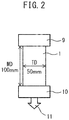
- a laminate type battery comprising a wound body in which a laminate of electrodes and separators is wound in a flat form in MD
- separators which exhibits a favorable short-circuit resistance in a short-circuit test under severe conditions are required in the field of in-vehicle batteries, etc., where separators are required to have a higher level of safety.
- one of the objects of the present invention is to provide a polyolefin microporous membrane that can prevent separator-derived battery distortion and reduction of permeability and cycle characteristics upon hot pressing.
- another object is to provide a polyolefin microporous membrane having a favorable short-circuit resistance in a short-circuit test under severe conditions.
- the inventors have found that the problems can be solved by the laminated structure, the proportion of polypropylene in each layer, the specific ranges of thermal shrinkage in TD under a load applied in MD, etc., and thus have completed the present invention.
- the present invention is as follows:
- the present invention can provide a polyolefin microporous membrane that can provide a separator capable of preventing distortion of a battery and reduction of battery characteristics upon hot pressing while maintaining safety.
- the present invention can provide a polyolefin microporous membrane that can provide a separator having a favorable short-circuit resistance in a short-circuit test under severe conditions, such as a nail puncture test, etc.
- the polyolefin microporous membrane of the present embodiment has a laminated structure of two or more layers having at least one layer of an A layer containing polyolefin and at least one layer of a B layer containing polyolefin.
- the polyolefin microporous membrane preferably has a laminated structure of three or more layers having at least one B layer(s) each on both sides (both surfaces) of the A layer.
- the laminated structure is not limited to a two-layer structure of "A layer-B layer” or a three-layer structure of "B layer-A layer-B layer” provided that the laminated structure has one layer each of the A layer and the B layer.
- the polyolefin microporous membrane may include, for example, one or more additional layers formed on either one or both of the B layers or between the A layer and the B layer.
- the additional layer include, for example: a layer containing polyolefin; a heat resistant layer containing inorganic particles and a heat resistant resin, such as a crosslinkable polymer, etc.; and an adhesive layer containing an adhesive polymer, etc.
- the A layer and the B layer contain polyolefin and are preferably consisting of polyolefin.
- the polyolefin in the A layer and the B layer may be in the form of a polyolefin microporous material, for example, a polyolefin-based fiber woven fabric (woven cloth), a polyolefin-based fiber non-woven fabric, etc.
- the polyolefin include, for example, homopolymers, copolymers, or multistage polymers, etc., obtained by using monomers, such as ethylene, propylene, 1-butene, 4-methyl-1-pentene, 1-hexene, 1-octene, etc. These polymers may be used alone or in combination of two or more.
- the polyolefin is preferably at least one selected from the group consisting of polyethylene, polypropylene, and copolymers thereof from the viewpoint of shutdown and meltdown characteristics of the separator.
- polyethylene examples include low density polyethylene (LDPE), linear low density polyethylene (LLDPE), medium density polyethylene (MDPE), high density polyethylene (HDPE), high molecular weight polyethylene (HMWPE), ultrahigh molecular weight polyethylene (UHMWPE), etc.
- LDPE low density polyethylene
- LLDPE linear low density polyethylene
- MDPE medium density polyethylene
- HDPE high density polyethylene
- HMWPE high molecular weight polyethylene
- UHMWPE ultrahigh molecular weight polyethylene
- the high molecular weight polyethylene refers to a polyethylene having a viscosity-average molecular weight (Mv) of 100,000 or more.
- ultrahigh molecular weight polyethylene has a Mv of 1,000,000 or more
- the definition of the high molecular weight polyethylene (HMWPE) in the present description includes UHMWPE.
- the high density polyethylene refers to a polyethylene having a density of 0.942 to 0.970 g/cm 3 .
- the density of polyethylene refers to a value measured according to D) density gradient tube method described in JIS K7112 (1999).
- polypropylene examples include isotactic polypropylene, syndiotactic polypropylene, atactic polypropylene, etc.
- a copolymer of ethylene and propylene include an ethylenepropylene random copolymer, ethylene propylene rubber, etc.
- the A layer contains a polypropylene, based on the total weight of the resin components constituting the A layer, in an amount of preferably 0% by weight or more and less than 3% by weight, more preferably 0% by weight or more and less than 1% by weight, and most preferably the layer A does not contain a polypropylene.
- the A layer contains less than 3% by weight of a polypropylene, the mechanical strength and elongation of the polyolefin microporous membrane become more preferable.
- the amount of polyethylene based on the total weight of the resin components constituting the A layer is preferably 90% by weight or more and 100% by weight or less, more preferably 97% by weight or more and 100% by weight or less, and most preferably the A layer is consisting of polyethylene.
- the shutdown function of the polyolefin microporous membrane becomes more preferable.
- the proportion of a thickness of the A layer to the entire thickness (total thickness) of the polyolefin microporous membrane is 40% or more and 90% or less, preferably 50% or more and 90% or less, more preferably 55% or more and 85% or less, and even more preferably 60% or more and 80% or less.
- the proportion of the thickness of the A layer is 90% or less, the melting point of the polyolefin microporous membrane as a whole does not become too low, which can prevent thermal shrinkage of the separator, and moreover, prevent reduction of permeability of the A layer due to clogging up the pores thereof upon hot pressing.
- the A layer has a lower polypropylene content than the B layer, it is likely to have a higher toughness and a lower melting point than the B layer. Therefore, when the proportion of the thickness of the A layer is 50% or more, the A layer serves as a base material for the polyolefin microporous membrane, which can lead to a preferable mechanical strength and elongation of the polyolefin microporous membrane and the shutdown function.
- the B layer contains more polypropylene than the A layer, i.e., when a proportion of polypropylene contained in the A layer is represented by PPA (% by weight) and a proportion of polypropylene contained in the B layer is represented by PPB (% by weight), then PPB is greater than PPA.
- the lower limit of the amount of polypropylene contained in the B layer is preferably 1% by weight or more, more preferably 3% by weight or more, still more preferably 4% by weight or more, even still more preferably 5% by weight or more, and most preferably 10% by weight or more, based on the total weight of resin components constituting the B layer.
- the upper limit of the amount of polypropylene contained in the B layer is preferably 30% by weight or less, more preferably 27% by weight or less, still more preferably 25% by weight or less, even still more preferably 20% by weight or less, and most preferably 18% by weight or less, based on the total weight of resin components constituting the B layer.
- the layer B contains polypropylene in a range of, for example, 1% by weight or more and 30% by weight or less, or 1% by weight or more and less than 30% by weight, and preferably 5% by weight or more and less than 30% by weight, more preferably 5% by weight and 25% by weight or less, and still more preferably 10% by weight or more and 20% by weight or less.
- the distortion can be prevented since the thermal shrinkage in TD can be prevented when the polyolefin microporous membrane is hot pressed under a certain tension applied in MD.
- the B layer containing a polypropylene within the above range can prevent reduction of permeability of the separator due to melting of the surface layer upon hot pressing to, while maintaining a shutdown function of the separator.
- the amount of polyethylene based on the total weight of resin components constituting the B layer is preferably 60% by weight or more and 99% by weight or less, more preferably 70% by weight or more and 95% by weight or less, still more preferably 75% by weight or more and 90% by weight or less, and most preferably the B layer is consisting of polypropylene and polyethylene.
- the polyethylene contained in the A layer and the B layer has a viscosity-average molecular weight of preferably 50,000 or more and 10,000,000 or less, more preferably 100,000 or more and 5,000,000 or less, further preferably 120,000 or more and 3,000,000 or less, and most preferably 150,000 or more and 1,000,000 or less.
- a polyolefin microporous membrane having sufficient strength can be obtained, and when the molecular weight is 10,000,000 or less, the internal stress upon stretching does not become excessively large, thereby excessive heat shrinkage can be prevented.
- the polyethylene has a molecular weight distribution (Mw/Mn) of preferably 20 or less, more preferably 17 or less, still more preferably 14 or less, even still more preferably 10 or less, and most preferably 8 or less, and preferably 2 or more, more preferably 3 or more, and still more preferably 4 or more.
- Mw/Mn molecular weight distribution
- the molecular weight distribution of 20 or less can prevent reduction of tensile strength at break due to a low molecular weight component, and also prevent an increase in residual stress due to a high molecular weight component.
- the molecular weight distribution of 2 or more can prevent an increase in residual stress.
- the A layer preferably contains UHMWPE.
- the amount of UHMWPE based on the total weight of the polyolefin in the A layer is preferably 5% by weight or more, more preferably 10% by weight or more, and preferably 70% by weight or less, and more preferably 60% by weight or less.
- the A layer contains UHMWPE, the tensile elongation at break as a base material of the polyolefin microporous membrane having a laminated structure, can be improved.
- the B layer may include UHMPWE.
- the amount of UHMWPE is preferably less than 30% by weight, more preferably less than 20% by weight, and even more preferably less than 10% by weight, based on the total weight of the polyolefin in the B layer.
- the B layer contains UHMWPE, by setting the amount of UHMWPE in the B layer to 30% by weight or less, the melt viscosity does not increase too much when a temperature rises, and the shutdown response time does not become too late. This effect becomes remarkable when the polyolefin microporous membrane includes a structure of B layer-A layer-B layer in which the heat is transmitted first to the B layer.
- the proportion of UHMWPE to the total weight of polyolefin in the entire polyolefin microporous membrane is preferably less than 45% by weight, more preferably less than 35% by weight, and even more preferably less than 25% by weight.
- the ratio of UHMWPE to the total weight of polyolefin in the entire polyolefin microporous membrane is less than 45%, an increase in thermal shrinkage due to residual stress can be prevented.
- the B layer preferably contains LDPE.
- the amount of LDPE is preferably 3% by weight or more and more preferably 5% by weight or more, based on the total weight of the polyolefin in the B layer.
- the shutdown temperature and the shutdown response time can be lowered. This effect becomes remarkable when the polyolefin microporous membrane includes a structure of B layer-A layer-B layer in which the heat is transmitted first to the B layer.
- the A layer may contain LDPE.
- the amount of LDPE is preferably 25% by weight or less, more preferably 20% by weight or less, still more preferably 15% by weight or less, and even still more preferably 10% by weight or less, based on the total weight of the polyolefin in the A layer.
- the A layer contains LDPE, a decrease in the tensile elongation at break and mechanical strength can be prevented by adjusting the proportion of LDPE to 25% by weight or less. This effect becomes remarkable when the polyolefin microporous membrane includes a structure of B layer-A layer-B layer in which the A layer secures the mechanical strength as a base material.
- a proportion of LDPE to the total weight of polyolefin in the entire polyolefin microporous membrane is preferably 25% by weight or less, more preferably 18% by weight or less, and still more preferably 13% by weight or less.
- the proportion of LDPE to the total weight of polyolefin in the entire polyolefin microporous membrane being 25% by weight or less is capable of preventing an excessive decrease in crystallinity and preventing an increase in the thermal shrinkage, which is caused by shrinkage of the amorphous portion below the melting point due to residual stress, as well as a problem, such as a decrease in permeability and cycle characteristics. This effect is remarkable when the separator having an adhesive layer is used as a separator for laminate type secondary batteries that require a step of fusing the separator with electrodes by hot pressing.
- the lower limit of viscosity-average molecular weights of polypropylenes contained in the A layer and the B layer is preferably 50,000 or more, more preferably 100,000 or more, still more preferably 150,000 or more, even still more preferably 300,000 or more, and most preferably 350,000 or more.
- the upper limit of the viscosity-average molecular weights of the polypropylenes contained in the A layer and the B layer is preferably 10,000,000 or less, more preferably 5,000,000 or less, still more preferably 1,000,000 or less, and most preferably 800,000 or less.
- the range of the viscosity-average molecular weights of the polypropylenes contained in the A layer and the B layer is 50,000 or more and 10,000,000 or less, more preferably 100,000 or more and 5,000,000 or less, and most preferably 150,000 or more and 1,000,000 or less.
- the melt index of the polyolefin microporous membrane does not become too high, which can prevent melting upon hot pressing.
- the polyolefin microporous membrane having an excellent short-circuit resistance of a battery in the nail puncture test can be provided.
- the molecular weight distribution (Mw/Mn) of polypropylene is preferably 30 or less, more preferably 24 or less, and most preferably 12 or less.
- Mw/Mn molecular weight distribution
- miscibility with polyethylene is improved because of the less content of a low molecular weight polypropylene component, and a polyolefin microporous membrane derived from polypropylene having a higher heat resistance, can be obtained.
- the polypropylenes contained in the A layer and the B layer are each preferably a homopolymer.
- the amount of the homopolymer is preferably 90% by weight or more, more preferably 95% by weight or more, still more preferably 98% by weight or more, and most preferably 100% by weight (all), based on the total weight of polypropylenes in the entire polyolefin microporous membrane.
- the homopolymer is 90% by weight or more, further melting of the microporous membrane due to a temperature rise when short-circuited can be prevented.
- the homopolymer since the homopolymer has a high crystallinity, phase separation from the plasticizer is likely to proceed, and a membrane having a preferred porosity and high permeability is likely to be obtained.
- the homopolymer has few amorphous portions, and thus is capable of preventing an increase in thermal shrinkage due to shrinkage of an amorphous portion produced by heating below the melting point or by residual stress, and is also capable of preventing a reduction of permeability and cycle characteristics due to the shrinkage of the amorphous portion.
- this effect is remarkable in a separator of laminate type secondary batteries, which require a step of fusing the separator having an adhesive layer with electrodes by hot pressing.
- the proportion of the thickness of the B layer to the total thickness of the polyolefin microporous membrane is preferably 10% or more and 50% or less, more preferably 15% or more and 45% or less, and still more preferably 20% or more and 40% or less.
- the A layer and B layer may contain resins, such as polyethylene terephthalate, polycycloolefin, polyether sulfone, polyamide, polyimide, polyimide amide, polyaramid, nylon, polytetrafluoroethylene, polyvinylidene difluoride, etc., in addition to the polyolefins listed above.
- resins such as polyethylene terephthalate, polycycloolefin, polyether sulfone, polyamide, polyimide, polyimide amide, polyaramid, nylon, polytetrafluoroethylene, polyvinylidene difluoride, etc.
- the proportion of molecules having a molecular weight of 3,000,000 or more, in an integration curve of gel permeation chromatography (GPC) measurement of polyolefin microporous membrane is preferably 10% by weight or less, more preferably 9% by weight or less, still more preferably 8% by weight or less, and preferably 3% by weight or more, more preferably 5% by weight or more.
- the proportion of molecules having a molecular weight of 30,000 or less, in the integration curve of the gel permeation chromatography (GPC) measurement of the polyolefin microporous membrane is preferably 3% by weight or less, more preferably 2.8% by weight or less, most preferably 2.5% by weight or less, and preferably 0.5% by weight or more, more preferably 0.8% by weight or more.
- the high molecular weight polyethylene component is 10% by weight or less, the viscosity of the polyolefin microporous membrane does not become too high, which can secure the shutdown function.
- the polyethylene component having a low molecular weight is 3.0% by weight or less, it is possible to prevent the polyolefin microporous membrane from clogging up the pores thereof upon hot pressing and lowering the permeability.
- the content of the inorganic particles in the layer B is preferably less than 5% by weight, more preferably less than 3% by weight, and most preferably no inorganic particles are contained.
- the content of the inorganic particles is less than 5% by weight, it is possible to effectively prevent batteries from swelling, etc., due to gas generation. This effect becomes more remarkable in a laminated battery, which the external body thereof is easily deformed.
- the B layer contains inorganic particles in an amount of 5% by weight or more, mechanical safety tend to be lowered due to a decrease in elongation, since the inorganic particles can be a starting point of breakage, or cycle characteristics tend to be deteriorated due to disorder in pore uniformity, which is not preferred.
- the inorganic material is not particularly limited, but includes, for example: oxide-based ceramics, such as alumina, silica (silicon oxide), titania, zirconia, magnesia, ceria, yttria, zinc oxide, iron oxide, etc.; nitride-based ceramics, such as silicon nitride, titanium nitride, boron nitride, etc.; ceramics, such as silicon carbide, calcium carbonate, aluminum sulfate, barium sulfate, aluminum hydroxide, potassium titanate, talc, kaolin clay, kaolinite, halloysite, pyrophyllite, montmorillonite, sericite, mica, amesite, bentonite, asbestos, zeolite, calcium silicate, magnesium silicate, kieselguhr, silica sand, etc.; and glass fibers. These may be used alone or in combination of two or more. Among these, preferable inorganic particle is at least one
- the polyolefin microporous membrane of the present embodiment has a thermal shrinkage in TD at 120 °C of 10% or more and 40% or less, preferably 15% or more and 35% or less, and more preferably 20% or more and 30% or less, which is measured under a constant load applied to the MD.
- the inventors have found that, for example, in the case of a laminate type battery comprising a wound body, which is obtained by winding a laminate of electrodes and a separator in a flat shape in MD, the separator is wound in MD and thus is constrained in MD during hot pressing. Therefore, when the thermal shrinkage in TD measured as described above is 40% or less, the short-circuiting upon adhesion pressing can be effectively prevented.
- the thermal shrinkage is 10% or more, the deflection of the polyolefin microporous membrane and the battery molding failure can be effectively prevented.
- the TD heat shrinkage of the membrane being constrained in MD is within the above range, decrease in voltage can be moderated since it is assumed that a short-circuited portion in the periphery of a nail hardly spread even if the battery temperature rises in the nail puncture test.
- MI Melt Index
- the polyolefin microporous membrane of the present embodiment has a melt index (MI) under a load of 21.6 kgf at 190 °C, which is preferably 0.01 g/lOmin or more and 3.0 g/lOmin or less, more preferably 0.05 g/lOmin or more and 1.5 g/lOmin or less, still more preferably 0.1 g/lOmin or more and 0.6 g/lOmin or less, and most preferably 0.12 g/lOmin or more and 0.5 g/lOmin or less.
- MI melt index
- the MI of the polyolefin microporous membrane can be controlled by the type, proportion, viscosity-average molecular weight, and molecular weight distribution of the polyolefin raw materials used.
- the MI of the A layer under a load of 21.6 kgf at 190 °C is preferably 0.30 g/lOmin or less, more preferably 0.26 g/lOmin or less, further preferably 0.22 g/lOmin or less, and preferably 0.01 g/lOmin or more, more preferably 0.03 g/lOmin or more, and further preferably 0.06 g/lOmin or more. It is assumed that the MI of the A layer of 0.30 g/min or less enables the battery to hold the shape even if the temperature in the battery rises upon short-circuiting, and can prevent a short-circuit area from increasing, and thus can prevent thermal runaway.
- the MI of the B layer under a load of 21.6 kgf at 190 °C is preferably more than 0.3 g/min, more preferably more than 0.35 g/min, further preferably more than 0.40 g/min, and preferably 2.0 g/min or less, more preferably 1.8 g/min or less, and further preferably 1.6 g/min or less. It is assumed that the MI of the B layer of more than 0.3 g/min enables a membrane to quickly melt and shutdown when the temperature inside the battery rises due to short-circuiting, which can increase the resistance and inhibit heat generation. It is assumed that when the MI of the B layer is 2.0 g/min or less, the molten resin cannot flow even if the temperature in the battery rises due to short-circuiting, which can prevent the short-circuited area from increasing.
- the ratio of MI of the B layer to that of the A layer is preferably 1.5 or more, more preferably 1.8 or more, further preferably 2.1 or more, and preferably 20.0 or less, more preferably 18.0 or less, and further preferably 16.0 or less. It is assumed that when the ratio of MI of the B layer to that of the A layer is 1.5 or more, the resistance is increased by the molten B layer penetrating into the pores of the A layer when the temperature in the battery rises due to short-circuiting, which can prevent a rapid drop in voltage, while maintaining and supporting the shape of the A layer. When the ratio of MI of the B layer to that of the A layer is 20.0 or less, the affinity of the interface between the A layer and the B layer can be ensured, which can stabilizes the layer structure.
- the polyolefin microporous membrane of the present embodiment preferably has a shutdown response time of 8 seconds or longer and 30 seconds or shorter, more preferably 12 seconds or longer and 22 seconds or shorter, still more preferably 14 seconds or longer and 20 seconds or shorter, and even still more preferably 16 seconds or longer and 18 seconds or shorter.
- shutdown response time refers to time until an electrical resistance value reaches from 10 2 ⁇ to 10 3 ⁇ in the shutdown characteristic test described in Examples.
- the shutdown response time is 12 seconds or longer, it is possible to prevent a decrease in permeability due to clogged micropores upon hot pressing.
- a shutdown response time of 22 seconds or shorter is preferable since the safety can be further enhanced, which is required for in-vehicle applications.
- the polyolefin microporous membrane of the present embodiment has a shutdown temperature of preferably 200 °C or lower, more preferably 170 °C or lower, and still more preferably 150 °C or lower, and preferably 135 °C or higher, more preferably 138 °C or higher, and even more preferably 140 °C or more.
- the membrane rupture temperature of the polyolefin microporous membrane of the present embodiment is preferably 100 °C or higher, more preferably 130 °C or higher, further preferably 150 °C or higher, even further preferably 170 °C or higher, and most preferably higher than 170 °C, and preferably 300 °C or lower, more preferably 280 °C or lower.
- shutdown temperature is a value obtained by rounding off the first decimal place of the temperature value when an electrical resistance value of the microporous film once reached 10 3 ⁇ in the shutdown characteristic test described in Examples.
- the “membrane rupture temperature” refers to, in the shutdown characteristic test described in Examples, a temperature at the time when an electrical resistance value again falls below 10 3 ⁇ after the rupture of the membrane with pores that are clogged due to an elevated temperature after the shutdown. It is preferable that the shutdown temperature of the polyolefin microporous membrane is 150°C or lower and the membrane rupture temperature is higher than 170°C, since thermal runaway upon an internal short-circuiting of the battery can be prevented. When the shutdown temperature is 135°C or higher, a decrease in permeability upon adhesion pressing can be prevented.
- the polyolefin microporous membrane of the present embodiment has a puncture strength (gf/10 ⁇ m) per 10 ⁇ m membrane thickness of preferably 170 gf/10 ⁇ m or more, more preferably 180 gf/10 ⁇ m or more, still more preferably 190 gf/10 ⁇ m or more, and preferably 1500 gf/10 ⁇ m or less, more preferably 1300 gf/10 ⁇ m or less.
- a puncture strength is 170 gf/10 ⁇ m or more and a laminated battery is fabricated by using such a microporous polyolefin membranes, microthinning and membrane rupture upon contact with the uneven portion of the electrode surface can be inhibited, which can reduce battery failure due to a micro-short-circuit.
- this effect becomes remarkable in a separator of laminate type secondary batteries, which requires a step of fusing the separator having an adhesive layer with electrodes by hot pressing.
- the polyolefin microporous membrane of the present embodiment has an air permeability (sec/100cc) of preferably 30 sec/100cc or longer, more preferably 40 sec/100cc or longer, still more preferably 50 sec/100cc or longer, and preferably 500 sec/100cc or shorter, more preferably 400 sec/100cc or shorter, further preferably 300 sec/100cc or shorter, even further preferably 200 sec/100cc or shorter, and most preferably 100 sec/100cc or shorter.
- the air permeability of 30 sec/100cc or longer is capable of preventing a micro-short-circuiting of the battery.
- the air permeability of 500 sec/100cc or shorter enables to secure an output of the battery.
- the polyolefin microporous membrane of the present embodiment has a tensile strength at break in TD of 100 kgf/cm 2 or more and 5000 kgf/cm 2 or less, more preferably 300 kgf/cm 2 or more and 3000 kgf/cm 2 or less, and even more preferably 500 kgf/cm 2 or more and 2000 kgf/cm 2 or less.
- the tensile strength at break in TD of 100 kgf/cm 2 or more enables to reduce the possibility of separator rupture when the battery is deformed by an external force, etc. It is preferable that the tensile strength at break in TD is 5000 kgf/cm 2 or less, since the residual stress can be reduced, which can prevent the thermal shrinkage. This effect becomes more remarkable in a laminate type battery in which the external body is prone to be deformed.
- the polyolefin microporous membrane of the present embodiment preferably has a tensile elongation in TD of 10% or more and 500% or less, more preferably 30% or more and 300% or less, and even more preferably 50% or more and 200% or less.
- the elongation in TD of 10% or more enables to reduce the possibility of separator rupture when the battery is deformed by an external force, etc.
- it also enables to reduce the possibility of battery failure due to a micro-short-circuiting via pinholes in the polyolefin microporous membrane created by distortion of a micro segment generated when the microporous polyolefin membrane and electrodes are laminated in the presence of fine foreign substances.
- the TD elongation of 500% or less enables to prevent the separator from tearing in the longitudinal direction (tearing in MD) when the battery is deformed by an external force, etc., since the separator is not oriented too much in MD. This effect becomes more remarkable in a laminate type battery in which the exterior body is prone to be deformed.
- the polyolefin microporous membrane preferably has a small electron conductivity, an ionic conductivity, a high resistance to an organic solvent, and a fine pore size.
- the polyolefin microporous membrane can be utilized as a separator for lithium ion secondary batteries, and in particular, can be preferably used as a separator for laminate type lithium ion secondary batteries.
- the thickness of the polyolefin microporous membrane is preferably 0.1 ⁇ m or more and 100 ⁇ m or less, more preferably 1 ⁇ m or more and 50 ⁇ m or less, further preferably 3 ⁇ m or more and 25 ⁇ m or less, still more preferably 15 ⁇ m or less, and most preferably 10 ⁇ m or less.
- the thickness of the polyolefin microporous membrane is preferably 0.1 ⁇ m or more from the viewpoint of mechanical strength, and preferably 100 ⁇ m or less from the viewpoint of increasing a capacity of lithium ion secondary batteries.
- the total thickness of the polyolefin microporous membrane can be adjusted, for example, by controlling a die lip gap, stretching ratio in a stretching step, etc.
- the average pore size of the polyolefin microporous membrane is preferably 0.03 ⁇ m or more and 0.70 ⁇ m or less, more preferably 0.04 ⁇ m or more and 0.20 ⁇ m or less, and still more preferably 0.05 ⁇ m or more and 0.10 ⁇ m or less.
- the average pore size of the polyolefin microporous membrane is preferably 0.0 3 ⁇ m or more and 0.70 ⁇ m or less from the viewpoint of high ion conductivity and voltage resistance.
- the average pore size can be adjusted by controlling the composition ratio of polyolefin, cooling rate of an extruded sheet, stretching temperature, stretching ratio, heat setting temperature, stretching ratio upon heat setting, and relaxation ratio upon heat setting, and by combining these.
- the porosity of the polyolefin microporous membrane is preferably 25% or more and 95% or less, more preferably 30% or more and 65% or less, and still more preferably 35% or more and 55% or less.
- the porosity of the polyolefin microporous membrane is preferably 25% or more from the viewpoint of improving ion conductivity, and preferably 95% or less from the viewpoint of voltage resistance characteristics.
- the porosity of the polyolefin microporous membrane can be controlled by the mixing ratio of the polyolefin resin composition and the plasticizer, stretching temperature, stretching ratio, heat setting temperature, stretching ratio upon heat setting, and relaxation ratio upon heat setting, and by combining these.
- the polyolefin microporous membrane has a viscosity-average molecular weight (Mv) of preferably 30,000 or more and 12,000,000 or less, more preferably 50,000 or more and 2,000,000 or less, still more preferably 100,000 or more and 1,000,000 or less, and most preferably 500,000 or more and 900,000 or less.
- Mv viscosity-average molecular weight
- the viscosity-average molecular weight of 30,000 or more is preferable, since the melt tension upon melt-molding is improved and moldability becomes preferable, and the polyolefin microporous membrane having a high strength tends to be obtained due to entanglement between polymers.
- the viscosity-average molecular weight is 12,000,000 or less, uniform melt-kneading is facilitated, which is preferable because it can lead to excellent sheet formability, in particular thickness stability. Furthermore, the viscosity-average molecular weight of less than 1,000,000 is preferable when the polyolefin resin porous membrane is used as a separator for secondary batteries, since pores thereof are prone to be clogged up when a temperature rises, which is preferable because preferable shutdown function tends to be achieved.
- Methods for producing a polyolefin microporous membrane are not particularly restricted, and publicly known production methods can be used.
- the method includes, for example, the following methods:
- the method (1) in which a polyolefin resin composition and a pore-forming material are melt-kneaded to be molded into a sheet and the pore-forming material is extracting therefrom, will be described.
- the polyolefin resin composition used for an A layer and the pore-forming material are melt-kneaded to obtain a melt-kneaded product A
- a polyolefin resin composition used for a B-layer and the pore-forming material are melt-kneaded to obtain a melt-kneaded product B.
- a method for melt-kneading includes, for example, a method comprising feeding a polyolefin resin and optionally other additives into a resin-kneading apparatus, such as an extruder, kneader, laboplastomill, kneading roll, Banbury mixer, etc., and introducing and kneading a pore-forming material at an arbitrary ratio while heat-melting the resin components.
- a resin-kneading apparatus such as an extruder, kneader, laboplastomill, kneading roll, Banbury mixer, etc.
- the pore-forming material may include a plasticizer, an inorganic material, or combination thereof.
- a non-volatile solvent that can form a uniform solution above the melting point of polyolefin is preferably used.
- a non-volatile solvent include, for example, hydrocarbons, such as liquid paraffin, paraffin wax, etc.; esters, such as dioctyl phthalate, dibutyl phthalate, etc.; and higher alcohols, such as oleyl alcohol, stearyl alcohol, etc. These plasticizers may be recovered by distillation, etc., after extraction, and reutilized.
- the polyolefin resin, other additive and plasticizer are preliminarily kneaded at a prescribed ratio by using a Henschel mixer, etc., before introduced into the resin-kneading apparatus. More preferably, in the pre-kneading, only a portion of the plasticizer to be used is fed, and the remaining plasticizer is side-fed into the resin kneading apparatus and kneaded while being appropriately heated.
- the dispersibility of the plasticizer is improved, and when stretching a melt-kneaded product of the resin composition and the plasticizer into a sheet in a later step, it tends to be stretchable at a high ratio without a membrane rupture.
- the plasticizer is preferably a liquid paraffin, because when the polyolefin resin is polyethylene or polypropylene, liquid paraffin is highly compatible with them, and even when the melt-kneaded product is stretched, interfacial separation between the resin and the plasticizer hardly occurs, which is prone to facilitate uniform stretching.
- the ratio of the polyolefin resin composition to the pore-forming material is not particularly limited provided that these can be melt-kneaded uniformly to be mold into a sheet form.
- the weight fraction of the pore-forming material in the composition consisting of the polyolefin resin composition and the pore-forming material is preferably 20% by weight or more, more preferably 25% by weight or more, further more preferably 30% by weight or more, and preferably 38% by weight or less, more preferably 36% by weight or less, and further more preferably 34% by weight or less.
- the weight fraction of the pore-forming material is 38% by weight or less, the melt tension upon melt-molding tends to be enough to improve the moldability.
- the inorganic material used for the pore-forming material is not particularly limited, but include, for example: oxide-based ceramics, such as alumina, silica (silicon oxide), titania, zirconia, magnesia, ceria, yttria, zinc oxide, iron oxide, etc.; nitride-based ceramics, such as silicon nitride, titanium nitride, boron nitride, etc.; ceramics, such as silicon carbide, calcium carbonate, aluminum sulfate, aluminum hydroxide, potassium titanate, talc, kaolin clay, kaolinite, halloysite, pyrophyllite, montmorillonite, sericite, mica, amesite, bentonite, asbestos, zeolite, calcium silicate, magnesium silicate, kieselguhr, silica sand, etc.; and glass fibers. These may be used alone or in combination of two or more. Among these, silica, alumina and titani
- the ratio of the inorganic material as a pore-forming material in the polyolefin resin composition is preferably 5% by weight or more relative to the total weight thereof, and more preferably 10% by weight or more from the viewpoint of achieving favorable separation, and it is preferably 99% by weight or less and more preferably 95% by weight or less from a viewpoint of ensuring high strength.
- melt-kneaded products A and B of the resin compositions and the pore-forming materials are co-molded into a sheet that is laminated in the order of melt-kneaded product B - melt-kneaded product A - melt-kneaded product B, to obtain a sheet molded body.
- a method for producing the sheet molded body includes, for example: a method including co-extruding a melt-kneaded product into sheet form through a T die, etc., bringing it into contact with a heat conductor, and cooling to a temperature sufficiently lower than the crystallization temperature of the resin component to solidify it; and a method including extruding the melt-kneaded product A and melt-kneaded product B separately, bringing them into contact with a heat conductor and cooling to form each sheet, and then laminated them in the order of melt-kneaded product B - melt-kneaded product A - melt-kneaded product B.
- the heat conductor used for cooling and solidification includes a metal, water, air, plasticizer, etc.
- the die lip gap is preferably 200 ⁇ m or more and 3,000 ⁇ m or less, and more preferably 500 ⁇ m or more and 2,500 ⁇ m or less.
- the die lip gap is 200 ⁇ m or more, resin wastes, etc., are reduced, the influence on the membrane quality, such as streaks and defects is small, and the risk of the membrane rupture, etc., in the subsequent stretching step can be reduced.
- the die lip gap is 3,000 ⁇ m or less, the cooling rate is fast, which enables to prevent cooling unevenness, and the thickness stability of the sheet can be maintained.
- the sheet molded body may be also subjected to rolling.
- the rolling can be carried out by, for example, a press method by using a double belt press machine, etc.
- a degree of orientation, in particular, orientation of the surface layer can be increased.
- the rolling ratio by area is preferably more than 1 time and 3 times or less, and more preferably more than 1 time and 2 times or less.
- the rolling ratio is more than 1 time, the plane orientation is increased and the membrane strength of the finally obtained porous membrane tends to be increased.
- the rolling ratio is 3 times or less, the difference in orientation between the surface layer portion and the inside of the center is small, which tends to facilitate formation of a porous structure that is uniform in the thickness direction of the membrane.
- a method for removing the pore-forming material includes, for example, a method including immersing the sheet molded body in an extraction solvent to extract the pore-forming material and adequately drying it.
- the pore-forming material may be extracted either batchwise or continuously.
- an extraction solvent used when extracting the pore-forming material it is preferable to use a solvent which is a poor solvent for the polyolefin resin and is a good solvent for the pore-forming material and has a boiling point lower than the melting point of the polyolefin resin.
- Such extraction solvents include, for example, hydrocarbons, such as n-hexane, cyclohexane, etc.; halogenated hydrocarbons, such as methylene chloride, 1,1,1-trichloroethane, etc.; non-chlorinated halogenated solvents, such as hydrofluoroether, hydrofluorocarbon, etc.; alcohols, such as ethanol, isopropanol, etc.; ethers, such as diethyl ether, tetrahydrofuran, etc.; and ketones, such as acetone, methyl ethyl ketone, etc.
- Such extraction solvents may be recovered by distillation, etc., and reutilized.
- an aqueous solution of sodium hydroxide, potassium hydroxide, etc. may be used for the extraction solvent.
- the sheet molded body or the polyolefin microporous membrane is preferably subjected to stretching.
- the stretching may be carried out before extracting the pore-forming material from the sheet molded body.
- the stretching may also be carried out for the polyolefin microporous membrane in which the pore-forming material was extracted from the sheet molded body.
- it may be carried out before and after extracting the pore-forming material from the sheet molded body.
- a stretching method includes, for example: a method including uniaxial stretching, simultaneous biaxial stretching, sequential biaxial stretching, multistage stretching, multiple-time stretching, etc. Simultaneous biaxial stretching is preferable from the viewpoint of improvement in puncture strength, uniformity of stretching, and fuse property.
- Simultaneous biaxial stretching refers to a stretching method in which stretching in MD (the machine direction of a continuous processing of the microporous membrane) and stretching in TD (the transverse direction crossing the MD of the microporous membrane at an angle of 90°) are simultaneously carried out, and the stretching ratio in each direction may be different.
- Sequential biaxial stretching refers to a stretching method in which stretching in MD and stretching in TD are each carried out independently, and upon MD stretching or TD stretching, the other direction is in a non-constrained state or in anchored state with fixed length.
- the temperature upon stretching of the sheet molded body or the polyolefin microporous membrane is preferably 116 °C or higher, more preferably 118 °C or higher, and further preferably 120 °C or higher.
- the temperature upon stretching is preferably 129 °C or lower, more preferably 127 °C or lower, and further preferably 125 °C or lower.
- the temperature upon stretching, particularly the temperature during biaxial stretching of 116 °C or higher can impart sufficient strength to the polyolefin microporous membrane. Moreover, it enables to prevent an increase in thermal shrinkage due to excessive residual stress.
- the temperature upon stretching particularly the temperature upon biaxial stretching of 129 °C or lower can inhibit nonuniformity of the pore size distribution due to melting of the membrane surface, securing cycle performance when the battery is repeatedly charged and discharged.
- the surface condition can be uniform, which can prevent an adhesion condition from being non-uniform when hot pressing a membrane having an adhesive layer with electrodes.
- the stretching ratio is preferably in the range of 20 times or more and 100 times or less in terms of a ratio by area, more preferably in the range of 25 times or more and 70 times or less, and furthermore preferably in the range of 30 times or more and 50 times or less.
- the stretching ratio in each axial direction is preferably in the range of 4 times or more and 10 times or less in MD and 4 times or more and 10 times or less in TD, more preferably in the range of 5 times or more and 8 times or less in MD and 5 times or more and 8 times or less in TD, and furthermore preferably in the range of 5 times or more and 7 times or less in MD and 5 times or more and 7 times or less in TD.
- the strength of the obtained polyolefin microporous membrane tends to be further enhanced.
- the membrane shrinkage can be prevented because the residual stress does not become too large, a decrease in tensile elongation at break can be prevented, and further excessively large pores can be avoided.
- heat treatment can also be carried out with the aim of heat setting after the stretching step or after formation of the polyolefin microporous membrane.
- the polyolefin microporous membrane may be subjected to post-treatments, such as hydrophilic treatment with a surfactant, etc., and crosslinking treatment with ionizing radiation, etc.
- the polyolefin microporous membrane is preferably heat set by subjecting it to heat treatment.
- a method of the heat treatment includes, for example: a stretching step carried out at a prescribed temperature atmosphere and prescribed stretching ratio in order to adjusting physical properties and/or a relaxation step carried out at a prescribed temperature atmosphere and prescribed relaxation ratio in order to reduction of stretching stress.
- the relaxation step may be carried out after the stretching step.
- the ratio in MD and/or TD of the membrane in the stretching step is preferably 1.1 times or more, and more preferably 1.2 times or more, and preferably less than 2.3 times, more preferably less than 2.0 times.
- the product of the stretching ratios in MD and TD is preferably less than 3.5 times and more preferably less than 3.0 times, when the stretching ratios in MD and/or TD upon heat treatment is 1.1 times or more, it is possible to obtain the effects of increasing porosity and reducing thermal shrinkage.
- the stretching ratio of 2.3 times or less enables to prevent an excessive large pore size and a decrease in tensile elongation at break.
- the strain rate upon stretching is preferably 3 %/sec or more and 15 %/sec or less, more preferably 4 %/sec or more and 13 %/sec or less, and most preferably 5 %/sec or more and 11 %/sec or less.
- the relaxation step is a step of shrinking the membrane in MD and/or TD.
- the relaxation ratio is a value obtained by dividing the dimension of the membrane after the relaxation step by the dimension of the membrane before the relaxation step.
- the relaxation ratio refers to a value obtained by multiplying the relaxation ratio in MD and the relaxation ratio in TD.
- the relaxation ratio is preferably less than 1.0, more preferably less than 0.97, still more preferably less than 0.95, and most preferably less than 0.90.
- the relaxation ratio is preferably 0.4 or more, more preferably 0.6 or more, and still more preferably 0.8 or more, from the viewpoint of membrane quality.
- the absolute value of the strain rate upon relaxation is preferably 0.4 %/sec or more and 6.0 %/sec or less, more preferably 0.5 %/sec or more and 5.0 %/sec or less, and most preferably 0.6 %/sec or more and 4.0 %/sec or less.
- the relaxation step may be carried out in both directions of MD and TD, it may be carried out in either MD or TD.
- the thermal shrinkages in MD and/or TD can be controlled within a preferred range.
- the stretching and relaxation steps after the extraction of plasticizer are preferably carried out in TD.
- the temperature in the stretching and relaxation step is preferably from a weighted average value of the melting point (hereinafter also referred to as "Tm") of the polyolefin resin contained in the B layer minus 10 °C to the weighted average value plus 10 °C or lower, more preferably from the weighted average value minus 9 °C to the weighted average value plus 5 °C or lower, and furthermore preferably from the weighted average value of minus 8°C to the weighted average value plus 1°C or lower.
- Tm melting point
- the weighted average of the melting point can be obtained from the melting point obtained by differential scanning calorimetry (DSC) measurement of each raw material and the weight fraction of each raw material contained in the B layer.
- DSC differential scanning calorimetry
- an adhesive layer containing a thermoplastic resin can be disposed on the surface of the polyolefin microporous membrane.
- the thermoplastic resin contained in the adhesive layer is not particularly limited, but includes, for example: polyolefins, such as polyethylene, polypropylene, etc.; fluorine-containing resins, such as polyvinylidene difluoride, polytetrafluoroethylene, etc.; fluorine-containing rubbers, such as vinylidene fluoride-hexafluoropropylene copolymer, vinylidene fluoride-tetrafluoroethylene copolymer, vinylidene fluoride-hexafluoropropylene tetrafluoroethylene copolymer, ethylene-tetrafluoroethylene copolymer, etc.; rubbers, such as styrene-butadiene copolymer and hydride thereof, acrylonitrile-buta
- the method for forming the adhesive layer on the surface of the polyolefin microporous membrane is not particularly limited, and a publicly known method described in Japanese Patent Publication No. 3839706 , Japanese Unexamined Patent Publication No. 2013-203894 or Japanese Translation of PCT International Application Publication No. 2015-512124 , etc., can be used.
- the laminate type lithium ion secondary battery of the present embodiment has at least one structure in which a positive electrode and a negative electrode are laminated via the polyolefin porous membrane of the present embodiment in an external body consisting of a laminated film.
- a film in which a metal foil and a resin film are laminated is generally used, and such a laminated film includes, for example, a laminated film consisting of three layers of an outer layer resin film / metal foil / inner layer resin film.
- the outer layer resin film is used for preventing the metal foil from being damaged by contact, etc., and the resin includes, for example, resins, such as nylon, polyester, etc.
- the metal foil is used for preventing moisture and gas permeation, and the foil includes, for example, copper, aluminum, stainless steel foil, etc.
- the inner layer resin film protects the metal foil from the electrolytic solution contained therein, and melts and adheres to seal an opening upon heating, and such a resin includes, for example, polyolefin and acid-modified polyolefin.
- the proportion of polypropylene contained in the polyolefin microporous membrane can be determined by infrared spectroscopy (IR) or Raman spectroscopy.
- IR infrared spectroscopy
- Raman spectroscopy for example, in order to calculate the proportion of polypropylene to polyethylene, the IR spectrum of a 1473 cm -1 peak derived from polyethylene and a 1376 cm -1 peak derived from polypropylene are used as marker bands thereof, and the proportion of polypropylene can be calculated based on a calibration curve prepared from samples with known polypropylene contents.
- the proportion of polypropylene for each layer can be obtained, for example, by a method comprising calculating a proportion of polypropylene in a surface layer by a ATR-IR method, or by microscopic IR or microscopic Raman analysis of a cross section of the polyolefin microporous membrane.
- the polyolefin microporous membrane When inorganic particles are contained in the polyolefin microporous membrane, the polyolefin microporous membrane was immersed in caustic soda and heated to 90 °C for 30 minutes to remove the inorganic particles, and then washed with running water for 3 hours, and drying for 10 hours to prepare a sample.
- the sample was weighed, and 1,2,4-trichlorobenzene (TCB) as eluent was added so that the concentration thereof was 1 mg/ml.
- TAB 1,2,4-trichlorobenzene
- the sample was stored at 160 °C for 30 minutes by using a high-temperature dissolver, agitated at 160 °C for 1 hour, and visually confirmed that all of the samples were dissolved.
- the solution was filtered with a 0.5 ⁇ m filter while maintained at 160 °C to obtain a filtrate as a sample for a GPC measurement.
- PL-GPC220 (trademark) manufactured by Agilent Technologies as an GPC apparatus and two 30 cm columns of TSK gel GMHHR-H(20) HT (trademark) manufactured by Tosoh Corporation were used, and 500 ⁇ l of a GPC measurement sample prepared as described above was injected into the measurement apparatus, and GPC measurement was carried out at 160 °C.
- a calibration curve was prepared by using commercially available monodisperse polystyrenes having known molecular weights as standard substances, and molecular weight distribution data converted for polystyrene for each sample were obtained. Based on that, the proportion of molecules having a molecular weight of 3,000,000 or more and the proportion of molecules having a molecular weight of 30,000 or less were obtained for each sample.
- FIG. 2 is a schematic view explaining a method for measuring the thermal shrinkage (%) in TD in a state where a constant load is applied to the MD.
- the sample (1) was cut into a rectangle of 130 mm in MD and 50 mm in TD, one side of the short sides was fixed to a metal frame or metal rod with the heat-resistant tape (9) so that no wrinkles were created, and the other side was pinched with the clips (10) that is wider than the TD length of the sample, and was suspended with the clip on the bottom.
- the constant load (11) was applied to MD by hanging a weight on the clip. In this case, the distance from the lower end of the tape to the upper end of the clip was fixed to be 100 mm.
- Thermal shrinkage % in TD ( Length in TD before heating mm ⁇ Length in TD after heating mm ) / Length in TD before heating mm ⁇ 100
- MI Melt Index
- melt index (MI) of the polyolefin microporous membrane was measured.
- a load of 21.6 kgf was applied at 190 °C, the amount of resin (g) that flowed out from an orifice having a diameter of 1 mm and a length of 10 mm in 10 minutes was measured, and the value rounded to the first decimal place was taken as MI.
- the melt index of the A layer or the B layer can be measured by stripping the layer of the laminated polyolefin microporous membrane, respectively.
- FIG. 1 (A) shows a schematic diagram illustrating a measurement apparatus for a shutdown response time, shutdown temperature, and membrane rupture temperature (meltdown temperature).
- the sign 1 indicates a microporous film
- the signs 2A and 2B indicate nickel foils having a thickness of 10 ⁇ m
- the sings 3A and 3B indicate glass plates, respectively.
- the sign 4 denotes an electrical resistance measurement apparatus (LCR meter "AG-4411" (trademark) manufactured by Ando Electric Co., Ltd.), which is connected to the nickel foils 2A and 2B.
- the sign 5 denotes a thermocouple, connected to the thermometer 6.
- the sign 7 denotes a data collector, connected to the electrical resistance measurement apparatus 4 and the thermometer 6.
- the sign 8 denotes an oven for heating the microporous film 1.
- the microporous membrane 1 was overlaid on the nickel foil 2A, and longitudinally fixed with "Teflon" (registered trademark) tape (the hatched portion in the figure).
- the microporous film 1 impregnated with a 1 mol/liter lithium borofluoride solution (solvent: propylene carbonate/ethylene carbonate/y-butyl lactone 1/1/2), was used as an electrolytic solution.
- the nickel foil 2A and nickel foil 2B were combined in such a manner as to sandwich the microporous membrane 1 therebetween, and the two nickel foils were further sandwiched by the glass plates 3A and 3B on the both sides of the foils.
- the window portion of the foil 2B and the porous membrane 1 were positioned to be opposite to each other.
- the two glass plates 3A and 3B were fixed by pinching with a commercially available double clip.
- the thermocouple 5 was fixed to the glass plate with a "Teflon" (registered trademark) tape.
- the temperature when heating the microporous film 1, nickel foils 2A and 2B, glass plates 3A and 3B, and electrical resistance between the nickel foils 2A and 2B, were measured continuously.
- the temperature was raised from 25 °C to 200 °C at a rate of 2 °C/minute, and the electrical resistance value was measured with an alternating current of 1 kHz.
- the temperature at the time when the electrical resistance value of the microporous film once reached 10 3 ⁇ was measured and rounded off at the first decimal place, which was taken as a shutdown temperature. Thereafter, the temperature at the time when the electrical resistance value again fell below 10 3 ⁇ was taken as a membrane rupture temperature.
- the temperature at the time when the resistance value fell below 10 3 ⁇ was defined as the membrane rupture temperature.
- the time until the electrical resistance value reached from 10 2 ⁇ to 10 3 ⁇ was defined as a shutdown response time.
- the tensile test in TD was carried out by using a tensile tester (Shimadzu Autograph AG-A type), and the strength when a sample was broken was divided by a cross-sectional area of the sample before the test to obtain a TD tensile strength at break (kg/cm 2 ). Measurement conditions are as follows: temperature: 23 ⁇ 2 °C, humidity: 40%, sample shape: width 10 mm ⁇ length 100 mm, distance between chucks: 50 mm, and tensile speed: 200 mm/min. The tensile elongation (%) was obtained by dividing the amount of elongation (mm) up to breakage by the distance between chucks (50 mm) and then multiplying by 100.
- the intrinsic viscosity [ ⁇ ] at 135 °C in a decalin solvent based on ASTM-D4020 was measured.
- a temperature was raised from the room temperature to 200 °C at a rate of 10 °C/min (a first temperature raising step), then lowered the temperature at 10 °C/min to 30 °C (a first temperature lowering step), and again raised the temperature to 200 °C at a rate of 10 °C/min, i.e., a second temperature raising step, and the temperature at the minimum point of the endothermic peak in the second temperature raising step was taken as a melting point. The value was rounded off at the first decimal place to obtain the melting point.
- DSC differential scanning calorimetry
- polyethylene has a melting point between 120 °C and 140 °C
- polypropylene has a melting point between 140 °C and 170 °C, which are shown as an endothermic peak.
- the measurement was carried out by using a micro thickness gauge (type KBM, manufactured by Toyo Seiki Co., Ltd.) at room temperature of 23 °C and humidity of 40%. The measurement was carried out by using terminals having a terminal diameter of 5 mm under a load of 44 gf.
- a micro thickness gauge type KBM, manufactured by Toyo Seiki Co., Ltd.
- a permeability resistance of the polyolefin microporous membrane was measured by using a Gurley type air permeability tester G-B2 (trademark) manufactured by Toyo Seiki Co., Ltd., according to JIS P-8117, at temperature of 23 °C and humidity of 40%, and the permeability resistance was taken as air permeability.
- a microporous membrane was fixed with a sample holder having an opening diameter of 11.3 mm, by using a handy compression tester KES-G5 (trademark) manufactured by Kato Tech Co., Ltd. Subsequently, a puncture test was carried out by contacting a needle with a tip of a curvature radius of 0.5 mm with the center of the fixed microporous membrane at a puncture speed of 2 mm/sec, an atmospheric temperature of 23 °C and humidity of 40 %, to obtain a raw puncture strength (gf), which was taken as a maximum puncture load.
- KES-G5 trademark
- a puncture test was carried out by contacting a needle with a tip of a curvature radius of 0.5 mm with the center of the fixed microporous membrane at a puncture speed of 2 mm/sec, an atmospheric temperature of 23 °C and humidity of 40 %, to obtain a raw puncture strength (gf), which was taken as a maximum puncture load.
- a positive electrode, negative electrode, and electrolytic solution were prepared according to procedures a. to c. as follows.
- NMC nickel-manganese-cobalt composite oxide
- KS6 graphite powder
- AB acetylene black
- the slurry was coated on one surface of a 20 ⁇ m thick aluminum foil, which is used as a positive electrode current collector, by using a die coater, dried at 130 °C for 3 minutes, and then compression-molded by using a roll press machine to produce a positive electrode.
- the coating amount of the positive electrode active material was 109 g/m 2 .
- a slurry was prepared by dispersing 87.6% by weight of graphite powder A (density of 2.23 g/cm 3 , number-average particle size of 12.7 ⁇ m) and 9.7% by weight of graphite powder B (density of 2.27 g/cm 3 , number-average particle size of 6.5 ⁇ m) as negative electrode active materials; and 1.4% by weight (in terms of solid content) (solid content concentration of 1.83% by weight aqueous solution) of ammonium salt of carboxymethyl cellulose; and 1.7% by weight (in terms of solid content) (solid content concentration of 40% by weight aqueous solution) of a diene rubber-based latex as binders in purified water.
- the slurry was coated on one surface of a 12 ⁇ m thick copper foil, which is used as a negative electrode current collector, by using a die coater, dried at 120 °C for 3 minutes, and then compression-molded by using a roll press machine to produce a negative electrode.
- the coating amount of the negative electrode active material was 52 g/m 2 .
- a nonaqueous electrolytic solution was prepared by dissolving LiPF 6 as a solute to 1.0 mol/L in a mixed solvent of ethylene carbonate and ethyl methyl carbonate (at volume ratio of 1:2).
- an adhesive layer was formed on the polyolefin microporous membrane obtained in Examples and Comparative Examples.
- 64 parts of water and 0.25 parts of PELEX SS-L (45% solid content of sodium alkyldiphenyl ether disulfonate, manufactured by Kao Corporation) were charged into a reaction vessel equipped with a stirrer, reflux condenser, dropping tank and thermometer. Further, 0.15 parts of ammonium persulfate (2% aqueous solution) was added to the reaction vessel while maintaining the temperature of the reaction vessel at 80 °C. After 5 minutes following the addition, the emulsion prepared as follows was dropped from the dropping tank to the reaction vessel over 150 minutes.
- PELEX SS-L 45% solid content of sodium alkyldiphenyl ether disulfonate, manufactured by Kao Corporation
- An emulsion was prepared by mixing 24 parts of methyl methacrylate (MMA), 34 parts of butyl acrylate (BA), 1.5 parts of acrylic acid (AA), 0.1 parts of n-dodecyl mercaptan (nDDM), 1.5 parts of PELEX SS-L, 0.15 parts of ammonium persulfate and 69 parts of water by using a homomixer at 6000 rpm for 5 minutes. After the completion of dropping the emulsion, the temperature of the reaction vessel was maintained at 80 °C for 60 minutes, and then lowered to the room temperature.
- MMA methyl methacrylate
- BA butyl acrylate
- AA acrylic acid
- nDDM n-dodecyl mercaptan
- PELEX SS-L 0.15 parts of ammonium persulfate
- a 25% aqueous ammonia solution was added to the reaction vessel to adjust a pH to 8.0, water was further added to adjust the solid content to 40% by weight to prepare an acrylic emulsion as an adhesive coating solution.
- a coating solution was prepared by uniformly dispersing 7.5 parts by weight of the obtained adhesive coating solution in 92.5 parts by weight of water, and then the coating solution was coated on the surface of the polyolefin resin porous membrane by using a gravure coater. Water was removed by drying at 60 °C. Furthermore, the other side was also similarly coated with the coating solution and dried to obtain a separator for electricity storage devices having the adhesive layer.
- a laminate type secondary battery was fabricated by using the positive electrode, negative electrode, and nonaqueous electrolytic solution obtained in the a to c, and the separator obtained in d, wherein the laminate type secondary battery has a size of 100 mm ⁇ 60 mm and a capacity of 3 Ah, and was charged with a constant current and constant voltage (CCCV) for 3 hours under the conditions of a current value of 1 A (0.3C) and a cut-off battery voltage of 4.2V.
- CCCV constant current and constant voltage
- the laminate type secondary battery was placed on the iron plate in the explosion-proof booth.
- An iron nail having a diameter of 2.5 mm was stabbed at the center of the laminate type secondary battery at a rate of 3 mm/second at about 25 °C so as to pierce the center of the battery, and the nail was kept penetrating therethrough.
- the surface temperature of the laminate type battery was measured, evaluated and ranked as follows based on the maximum temperature reached.
- the separator obtained in each Example and Comparative Example was cut into a circle of 24 mm ⁇ , and the positive electrode and the negative electrode were each cut into a circle of 16 mm ⁇ .
- the negative electrode, the separator, and the positive electrode were stacked in this order so that the positive electrode and the active material surface of the negative electrode were opposed to each other, and these were pressed or heat pressed, and housed in a stainless steel container with a lid.
- the container and the lid were insulated, and the container was in contact with the copper foil of the negative electrode and the lid was in contact with the aluminum foil of the positive electrode, respectively.
- a simple battery having a capacity of 3 mAh was assembled by injecting 0.2 ml of the nonaqueous electrolytic solution into the container and sealing the container.
- the above simple battery was charged with a constant current to a voltage of 4.2 V at a current value of 1/3 C, charged with a constant voltage of 4.2 V for 8 hours, and subsequently discharged to a cut-off voltage of 3.0 V at a current of 1/3 C. then, the battery was charged with a constant current to a voltage of 4.2 V at a current value of 1 C, then charged with a constant voltage of 4.2 V for 3 hours, and further discharged to a cut-off voltage of 3.0 V with a current of 1 C. Finally, the battery was charged with a constant current to 4.2 V at a current value of 1 C, and was charged with a constant voltage of 4.2 V for 3 hours.
- 1 C refers to a current value for discharging the reference capacity of a battery in one hour.
- the battery was discharged to a discharge cut-off voltage of 3 V with a discharge current of 1 C under the condition of temperature of 25 °C, it was charged to a charge cut-off voltage of 4.2 V at a charge current of 1 C, and the discharge and the charge were regarded as one cycle, and these were repeated. Thereafter, the capacity retention ratio of a capacity after 200 cycles to an initial capacity (capacity at first cycle) were evaluated as cycle characteristics were evaluated and ranked according to the following criteria.
- the laminate sheet was cut into a certain constant size and formed into a pack shape (6 cm ⁇ 8 cm) with an impulse sealer (hereinafter referred to as "Lamipack").
- Lamipack an impulse sealer
- Three polyolefin microporous membranes cut into 10 cm ⁇ 10 cm were folded, and inserted into Lamipack, and vacuum dried at 80 °C for 12 hours.
- 0.4 mL of an electrolytic solution (LIPASTE-E2MEC / PF1; manufactured by Toyama Pharmaceutical Co., Ltd.) was added, and the opening of Lamipack was sealed with a sealer.
- the measurement was carried out twice for each polyolefin microporous membrane, and an average gas generation amount of 1.2 mL or more was ranked as C, the value of 0.8 mL or more and less than 1.2 mL was ranked as B, and the value of less than 0.8 mL was ranked as A.
- the positive electrode and negative electrode were laminated via the polyolefin microporous membrane and was wound into a flat shape to fabricate a wound laminated body, and the wound laminated body was put in a laminated film. Then it was pressed at a pressure of 1.0 MPa and 100 °C for 3 minutes, and the frequency of defects (warping, wrinkles, and edge face displacement) was visually inspected, evaluated and ranked as follows.
- a polyolefin microporous membrane having a two-type and three-layer laminated structure (B layer - A layer - B layer) was produced by the following procedures.
- a resin composition of the surface layer (B layer) contained 80 parts by weight of polyethylene having a melting point of 135 °C, viscosity-average molecular weight of 600,000 and molecular weight distribution of 6.0 and 20 parts by weight of homopolymer polypropylene having a melting point of 160 °C, viscosity-average molecular weight of 400,000, and molecular weight distribution of 10.0.
- a resin composition of the intermediate layer (A layer) contained 100 parts by weight of polyethylene having a viscosity-average molecular weight of 600,000 and molecular weight distribution of 6.0.
- liquid paraffin kinetic viscosity of 75.90 cSt at 37.78 °C
- a pore-forming material 200 parts by weight of liquid paraffin (kinetic viscosity of 75.90 cSt at 37.78 °C) as a pore-forming material was poured into each extruder by side feed, kneaded at 200 °C and 200 rpm, and extruded from a T-die which is positioned at the tip of the extruder and is capable of coextruding in a two-type and three-layer structure, so that the ratio of the total thickness of the surface layers and the thickness of the intermediate layer was 40:60.
- the sheet was cooled and solidified with a cast roll cooled to 25 °C to form a sheet having a thickness of 1.3 mm.
- the sheet was stretched 7 ⁇ 7 times at 124 °C by a simultaneous biaxial stretching machine, and then immersed in methylene chloride to extract and remove liquid paraffin. Thereafter, the sheet was dried and stretched 1.5 times in the width direction (TD) at a strain rate of 9.0 %/sec at 120 °C by a tenter stretching machine.
- the stretched sheet was subjected to heat treatment where the sheet was relaxed in the width direction (TD) at a strain rate of 2.0 %/sec at 133 °C so as to be relaxed 0.9 times in the width after the transverse stretching, to obtain a polyolefin microporous membrane which has a two-type and three-layer laminated structure with the two layers of the surface layers (B layer) of the same composition and the intermediate layer (A layer) of the different composition.
- a polyolefin microporous membrane was obtained under the same conditions as in Example 1 except that the extrusion was carrying out so that the ratio of the total thickness of the surface layers and the thickness of the intermediate layer was 20:80 upon extrusion from the T-die.
- a polyolefin microporous membrane was obtained under the same conditions as in Example 1 except that the resin composition of the surface layer (B layer) contained 95 parts by weight of polyethylene and 5 parts by weight of polypropylene.
- a polyolefin microporous membrane was obtained under the same conditions as in Example 1 except that the resin composition of the surface layer (B layer) contained 73 parts by weight of polyethylene and 27 parts by weight of polypropylene, and a temperature upon relaxation treatment of 138 °C.
- a polyolefin microporous membrane was obtained under the same conditions as in Example 1 except that the resin composition of the intermediate layer (A layer) contained 98 parts by weight of polyethylene having the melting point of 135 °C, viscosity-average molecular weight of 600,000 and molecular weight distribution of 6.0, and 2 parts by weight of polypropylene having the melting point of 160 °C, viscosity-average molecular weight of 400,000 and molecular weight distribution of 10.0.
- a microporous polyolefin membrane was obtained under the same conditions as in Example 1 except that the surface layer (B layer) contained polyethylene having the melting point of 135 °C, viscosity-average molecular weight of 700,000, molecular weight distribution of 3.0, and homopolymer polypropylene having a melting point of 165 °C, viscosity-average molecular weight of 400,000, and molecular weight distribution of 6.0, and the intermediate layer (A layer) contained polyethylene having the melting point of 135 °C, viscosity-average molecular weight of 700,000 and molecular weight distribution of 3.0, and the stretching treatment was carried out with a tenter stretching machine at the strain rate of 12 %/sec, and the relaxation treatment was carried out at the strain rate of 0.5 %/sec and a temperature of 132 °C.
- a polyolefin microporous membrane was obtained under the same conditions as in Example 1 except that the resin composition of the surface layer (B layer) contained 78 parts by weight of polyethylene having the melting point of 135 °C, viscosity-average molecular weight of 600,000, and molecular weight distribution of 6.0, 19 parts by weight of polypropylene having the melting point of 160 °C, viscosity-average molecular weight of 400,000, and molecular weight distribution of 10.0, and 3 parts by weight of silica "DM10C” (trademark, manufactured by Tokuyama Corporation and treated hydrophobically with dimethyldichlorosilane) having an average primary particle size of 15nm, and the temperature upon relaxation treatment was 140 °C.
- silica "DM10C” trademark, manufactured by Tokuyama Corporation and treated hydrophobically with dimethyldichlorosilane
- a microporous polyolefin membrane was obtained under the same conditions as in Example 1 except that the surface layer (B layer) contained polyethylene having the melting point of 135 °C, viscosity-average molecular weight of 500,000, and molecular weight distribution of 6.0, and homopolymer polypropylene having a melting point of 155 °C, viscosity-average molecular weight of 200,000, and molecular weight distribution of 6.0, and the intermediate layer (A layer) contained polyethylene having the melting point of 135°C, viscosity-average molecular weight of 500,000 and molecular weight distribution of 6.0, and the stretching was carried out with a tenter stretching machine at the strain rate of 4.0 %/sec, and the relaxation treatment was carried out at the strain rate of 3.5 %/sec and a temperature of 138 °C.
- a polyolefin microporous membrane was obtained under the same conditions as in Example 1 except that the surface layer (B layer) contained 70 parts by weight of polyethylene having the melting point of 135 °C, viscosity-average molecular weight of 700,000, and molecular weight distribution of 6.0, 20 parts of polyethylene having the melting point of 135 °C, viscosity-average molecular weight of 250,000 and molecular weight distribution of 6.0, and 10 parts of homopolymer polypropylene having the melting point of 160 °C, viscosity-average molecular weight of 400,000, and molecular weight distribution of 10.0, and the intermediate layer (A layer) contained polyethylene having the melting point of 135 °C, viscosity-average molecular weight of 700,000, and molecular weight distribution of 6.0, and the extrusion was carried out so that 300 parts by weight of liquid paraffin was injected into each extruder by side feed and the ratio of the total thickness of the surface layers and the thickness of the intermediate layer was
- a polyolefin microporous membrane was obtained under the same conditions as in Example 9 except that the intermediate layer (A layer) contained 40 parts by weight of polyethylene having the melting point of 135 °C, viscosity-average molecular weight of 2,000,000, and molecular weight distribution of 7.0 and 60 parts by weight of polyethylene having the melting point of 135 °C, viscosity-average molecular weight of 250,000, and molecular weight distribution of 6.0.
- a polyolefin microporous membrane was obtained under the same conditions as in Example 10 except that the surface layer (B layer) contained 70 parts by weight of polyethylene having the melting point of 135 °C, viscosity-average molecular weight of 700,000, and molecular weight distribution of 6.0, 15 parts by weight of polyethylene having the melting point of 135 °C, viscosity-average molecular weight 250,000, molecular weight distribution 6.0 parts, 15 parts by weight of low density polyethylene (LDPE) having a melting point of 130 °C, viscosity-average molecular weight of 150,000 and molecular weight distribution of 5.0, and 5 parts by weight of homopolymer polypropylene having the melting point of 160 °C, viscosity-average molecular weight of 400,000 and molecular weight distribution of 10.0.
- the surface layer (B layer) contained 70 parts by weight of polyethylene having the melting point of 135 °C, viscosity-average molecular weight of 700,000, and mole
- a polyolefin microporous membrane was obtained under the same conditions as in Example 11 except that the intermediate layer (A layer) contained 45 parts by weight of polyethylene having the melting point of 135 °C, viscosity-average molecular weight of 2,000,000, and molecular weight distribution of 7.0, 45 parts by weight of polyethylene having the melting point of 135 °C, viscosity-average molecular weight of 250,000, and molecular weight distribution of 6.0, and 10 parts by weight of low density polyethylene (LDPE) having a viscosity-average molecular weight of 150,000 and molecular weight distribution of 5.0.
- LDPE low density polyethylene
- a polyolefin microporous membrane was obtained under the same conditions as in Example 12 except that the surface layer (B layer) contained 75 parts by weight of polyethylene having the melting point of 135 °C, viscosity-average molecular weight of 700,000, and molecular weight distribution of 6.0, 20 parts by weight of polyethylene having the melting point of 135 °C, viscosity-average molecular weight of 250,000, and molecular weight distribution of 6.0, and 5 parts by weight of homopolymer polypropylene having the melting point of 160 °C, viscosity-average molecular weight of 400,000, and molecular weight distribution of 10.0.
- a polyolefin microporous membrane with a two-type and two-layer laminated structure was obtained by fabricating a polyolefin microporous membrane under the same conditions as in Example 10 except for using a laminated die that is capable of coextruding a two-type and two-layer structure.
- a polyolefin microporous membrane having a three-type and five-layer structure (B layer - C layer - A layer - C layer - B layer) was produced by the following procedures.
- the resin composition of layer A consisted of 40 parts by weight of polyethylene having the melting point of 135 °C, viscosity-average molecular weight of 2,000,000, and molecular weight distribution of 7.0, and 60 parts by weight of polyethylene having the melting point of 135 °C, viscosity-average molecular weight of 250,000, and molecular weight distribution of 6.0.
- tetrakis-(methylene-3-(3',5'-di-t-butyl-4'-hydroxyphenyl)propionate)methane was mixed.
- 300 parts by weight of liquid paraffin (kinetic viscosity at 37.78 °C of 75.90 cSt) as a pore forming-material was injected into each extruder by side feed, kneaded at 200 °C and 200 rpm, and extruded from the T-die disposed at the tip of the extruder.
- a 0.4 mm single-layer sheet was molded under the same conditions as those for the A layer by using the resin composition of B layer having 70 parts by weight of polyethylene having the melting point of 135 °C, viscosity-average molecular weight of 700,000, and molecular weight distribution of 6.0, 20 parts by weight of polyethylene having the melting point of 135 °C, viscosity-average molecular weight of 250,000, and molecular weight distribution of 6.0, and 10 parts by weight of homopolymer polypropylene having the melting point of 160 °C, viscosity-average molecular weight of 400,000, and molecular weight distribution of 10.0.
- a 0.4mm single-layer sheet was molded under the same conditions as those for the A layer, by using a resin composition of layer C having 90 parts by weight of polyethylene having the melting point of 135 °C, viscosity-average molecular weight of 500,000, and molecular weight distribution of 6.0 and 10 parts by weight of homopolymer polypropylene having the melting point of 160 °C, viscosity-average molecular weight of 400,000, and molecular weight distribution of 10.0.
- a polyolefin microporous membrane having a three-type and five-layer laminated structure was obtained by stacking the obtained three types of single-layer sheets so as to form a three-layer and five-layer laminated structure of B layer - C layer - A layer - C layer - B layer, under the same conditions following the simultaneous biaxial stretching as in Example 1.
- a polyolefin microporous membrane was obtained under the same conditions as in Example 10 except that the intermediate layer (A layer) contained 40 parts by weight of polyethylene having the melting point of 135 °C, viscosity-average molecular weight of 2,000,000, and molecular weight distribution of 7.0, 30 parts by weight of polyethylene having the melting point of 135 °C, viscosity-average molecular weight of 700,000, and molecular weight distribution of 6.0, and 30 parts by weight of polyethylene having the melting point of 135°C, viscosity-average molecular weight of 250,000, and molecular weight distribution of 6.0.
- a polyolefin microporous membrane was obtained under the same conditions as in Example 16 except that the surface layer (B layer) contained 40 parts by weight of polyethylene having the melting point of 135 °C, viscosity-average molecular weight of 700,000, and molecular weight distribution 6.0, 20 parts by weight of polyethylene having the melting point of 135 °C, viscosity-average molecular weight of 250,000, and molecular weight distribution 6.0, 30 parts by weight of low density polyethylene (LDPE) having the melting point of 130 °C, viscosity-average molecular weight of 150,000, and molecular weight distribution 5.0, and 10 parts by weight of homopolymer polypropylene having the melting point of 160 °C, viscosity-average molecular weight of 400,000, and molecular weight distribution 10.0.
- LDPE low density polyethylene
- a polyolefin microporous membrane was obtained under the same conditions as in Example 16 except that the surface layer (B layer) contained 8 parts by weight of polyethylene having the melting point of 135 °C, viscosity-average molecular weight of 2,000,000, and molecular weight distribution 7.0, 72 parts by weight of polyethylene having the melting point of 135 °C, viscosity-average molecular weight of 700,000, and molecular weight distribution 6.0, 15 parts by weight of polyethylene having the melting point of 135 °C, viscosity-average molecular weight of 250,000, and molecular weight distribution 6.0, and 5 parts by weight of homopolymer polypropylene having the melting point of 160 °C, viscosity-average molecular weight of 400,000, and molecular weight distribution 10.0.
- the surface layer (B layer) contained 8 parts by weight of polyethylene having the melting point of 135 °C, viscosity-average molecular weight of 2,000,000, and molecular weight distribution 7.0, 72
- a polyolefin microporous membrane was obtained under the same conditions as in Example 9 except that the polypropylene contained in the surface layer (B layer) was homopolymer polypropylene having the melting point of 160 °C, viscosity-average molecular weight of 1,000,000, and molecular weight distribution of 10.0.
- a single layer (only A layer) polyolefin microporous membrane was produced by the following procedures.
- the resin composition consisted of 90 parts by weight of polyethylene having a melting point of 135 °C, viscosity-average molecular weight of 500,000 and molecular weight distribution of 6.0 and 10 parts by weight of homopolymer polypropylene having a melting point of 160 °C, viscosity-average molecular weight of 400,000 and molecular weight distribution of 10.0.
- As an antioxidant 0.3 part by weight of tetrakis-(methylene-3-(3',5'-di-t-butyl-4'-hydroxyphenyl)propionate)methane was mixed thereto.
- liquid paraffin kinetic viscosity at 37.78 °C of 75.90 cSt
- the sheet was stretched 7 ⁇ 7 times at 118 °C with a simultaneous biaxial stretching machine, and then immersed in methylene chloride to extract and remove liquid paraffin. Thereafter, the sheet was dried and stretched 1.5 times in the width direction (TD) at a strain rate of 17.0 %/sec at 120 °C by a tenter stretching machine. Thereafter, the stretched sheet was subjected to heat treatment where the sheet was relaxed in the width direction (TD) at the strain rate of 0.3 %/sec at 133 °C so as to be relaxed 0.9 times in the width after the transverse stretching to obtain a single layer polyolefin microporous membrane.
- a polyolefin microporous membrane was obtained under the same conditions as in Comparative Example 1 except that the biaxial stretching was carried out at 124 °C, and the stretching using a tenter stretching machine was carried out at the strain rate of 7.0 %/sec, and the relaxation treatment was carried out at the strain rate of 0.9 %/sec.
- a polyolefin microporous membrane was obtained under the same conditions as in Example 1 except that the resin composition of the surface layer (B layer) contained 60 parts by weight of polyethylene and 40 parts by weight of polypropylene, and the temperature upon relaxation treatment was 137 °C.
- a polyolefin microporous membrane was obtained under the same conditions as in Example 1 except that the resin composition of the surface layer (B layer) contained 20 parts by weight of polyethylene and 80 parts by weight of polypropylene, and the temperature upon relaxation treatment of 140 °C.
- a polyolefin microporous membrane was obtained under the same conditions as in Example 1 except that the resin composition of the surface layer (B layer) contained 24 parts by weight of polyethylene having the melting point of 135 °C, viscosity-average molecular weight of 600,000 and molecular weight distribution of 6.0, 6 parts by weight of polypropylene having the melting point of 160 °C, viscosity-average molecular weight of 400,000 and molecular weight distribution of 10.0, and 70 parts by weight of silica "DM10C" (trademark, manufactured by Tokuyama Corporation and treated hydrophobically with dimethyldichlorosilane) having an average primary particle size of 15 nm, and the extrusion of the resin composition was carried out so that the ratio of the total thickness of the surface layers and the intermediate layer thickness was 25:75 upon extrusion from the T-die, and the temperature upon relaxation treatment was 145 °C.
- silica "DM10C” trademark, manufactured by Tokuyama Corporation and treated hydrophobically with
- a polyolefin microporous membrane was obtained under the same conditions as in Example 1 except that polyethylene having the melting point of 135 °C, viscosity-average molecular weight of 900,000, and molecular weight distribution of 6.0 was used as the polyethylene contained in the surface layer and the intermediate layer.
- a polyolefin microporous membrane was obtained under the same conditions as in Example 1 except for replacing the resin composition of the surface layer in Example 1 with the resin composition of the intermediate layer.
- a polyolefin microporous membrane was obtained under the same conditions as in Example 1 except that polyethylene having the melting point of 135 °C, viscosity-average molecular weight of 250,000, and molecular weight distribution of 6.0 was used as the polyethylene contained in the surface layer and the intermediate layer, the amount of liquid paraffin to be injected into the extruder was 150 parts by weight with respect to 100 parts of the resin, the extrusion was carried out so that the ratio of the total thickness of the surface layers and the thickness of the intermediate layer was 36:64 when extruded from the T-die, and the temperature upon relaxation treatment was 120 °C.
- This sheet was immersed in methyl ethyl ketone (MEK) to extract and remove liquid paraffin, and then dried to produce a microporous membrane B having a thickness of 18 ⁇ m.
- MEK methyl ethyl ketone
- 45.0 parts by weight of polyethylene having a melting point of 135 °C, viscosity-average molecular weight of 250,000 and molecular weight distribution of 6.0 and 55.0 parts by weight of liquid paraffin were melt-kneaded by an extruder equipped with a T-die at the tip thereof and then extruded to prepare a sheet having a thickness of 1300 ⁇ m.
- the sheet was stretched to 8 times in MD and 8 times in TD to produce a sheet having a thickness of 20 ⁇ m.
- microporous membrane A having a thickness of 18 ⁇ m.
- MEK methyl ethyl ketone
- Three layers were laminated in the form of microporous membrane B / microporous membrane A / microporous membrane B, stretched three times in the longitudinal direction while passing through several rolls heated to 110 °C, and then heated to 122 °C by passing through several rolls, to produce a longitudinally stretched membrane having three laminated sheets.
- the longitudinally stretched membrane was stretched twice at the strain rate of 4 %/sec in the transverse direction with a tenter heated to 118 °C, and then forcibly relaxed 0.9 times in the width after the stretching at the strain rate of 0.7 %/sec while heat-treated in a region of the tenter heated to 128 °C, to fabricate a three-layer microporous membrane of B/A/B type having a thickness of 10 ⁇ m.
- a polyolefin microporous membrane was obtained under the same conditions as in Comparative Example 9 except that the resin composition of the microporous membrane A contained 22.5 parts by weight of polyethylene having the melting point of 135 °C, viscosity-average molecular weight of 250,000 and molecular weight distribution of 6.0, 22.5 parts by weight of low density polyethylene (LDPE) having a viscosity-average molecular weight of 150,000 and molecular weight distribution of 5.0, and 55 parts by weight of liquid paraffin, and the resin composition of microporous membrane B contained 24 parts by weight of polyethylene having the melting point of 135 °C, viscosity-average molecular weight of 2,000,000, and molecular weight distribution of 7.0, and 16 parts by weight of homopolymer polypropylene having the melting point 160 °C, viscosity-average molecular weight of 400,000, and molecular weight distribution of 10.0, and 60 parts by weight of liquid paraffin, the simultaneous biaxial stretching ratio before liquid paraffin extraction was 8 times
- a polyolefin microporous membrane was obtained under the same conditions as in Comparative Example 9 except that the surface layer (B layer) contained 10 parts by weight of polyethylene having has the melting point of 135 °C, viscosity-average molecular weight of 2,000,000, and molecular weight distribution of 7.0, 87 parts by weight of polyethylene having the melting point of 135 °C, viscosity-average molecular weight of 250,000, and molecular weight distribution of 6.0, and 3 parts by weight of random polymer polypropylene having the melting point of 155 °C, viscosity-average molecular weight of 100,000 and molecular weight distribution of 3.0, and the intermediate layer (A layer) contained 18 parts by weight of polyethylene having the melting point of 135 °C, viscosity-average molecular weight of 2,000,000 and molecular weight distribution of 7.0 and 82 parts by weight of polyethylene having the melting point of 135 °C, viscosity-average molecular weight of 250,000 and molecular weight distribution
- a polyolefin microporous membrane was obtained under the same conditions as in Comparative Example 11 except that the surface layer (B layer) contained 97 parts by weight of polyethylene having has the melting point of 135 °C, viscosity-average molecular weight of 250,000, and molecular weight distribution of 6.0 and 3 parts by weight of homopolymer polypropylene having a melting point of 162 °C, viscosity-average molecular weight of 400,000 and molecular weight distribution of 10.0, and the intermediate layer (A layer) contained 20 parts by weight of polyethylene having the melting point of 135 °C, viscosity-average molecular weight of 2,000,000 and molecular weight distribution of 7.0 and 80 parts by weight of polyethylene having the melting point of 135 °C, viscosity-average molecular weight of 250,000 and molecular weight distribution 6.0, the simultaneous biaxial stretching temperature was 117 °C, the TD stretching ratio in the tenter stretching machine was 1.4 times, and the relaxation treatment was not carried out.
- a polyolefin microporous membrane was obtained under the same conditions as in Comparative Example 12 except that the surface layer (B layer) contained 92 parts by weight of polyethylene having has the melting point of 135 °C, viscosity-average molecular weight of 250,000, and molecular weight distribution of 6.0 and 8 parts by weight of random polymer polypropylene having the melting point of 155 °C, viscosity-average molecular weight of 100,000 and molecular weight distribution of 3.0, and the intermediate layer (A layer) contained 30 parts by weight of polyethylene having the melting point of 135 °C, viscosity-average molecular weight of 2,000,000 and molecular weight distribution of 7.0 and 70 parts by weight of polyethylene having the melting point of 135 °C, viscosity-average molecular weight of 250,000 and molecular weight distribution 6.0, the simultaneous biaxial stretching temperature was 115 °C, and the relaxation treatment was carried out at 124 °C and the relaxation ratio of 0.86 times the width after the TD stretching.
- a polyolefin microporous membrane was obtained under the same conditions as in Comparative Example 13 except that the surface layer (B layer) contained 80 parts by weight of polyethylene having has the melting point of 135 °C, viscosity-average molecular weight of 700,000, and molecular weight distribution of 6.0 and 20 parts by weight of homopolymer polypropylene having the melting point of 160 °C, viscosity-average molecular weight of 1,600,000 and molecular weight distribution of 10.0, and the intermediate layer (A layer) contained 40 parts by weight of polyethylene having the melting point of 135 °C, viscosity-average molecular weight of 2,000,000 and molecular weight distribution of 7.0 and 60 parts by weight of polyethylene having the melting point of 135 °C, viscosity-average molecular weight of 700,000 and molecular weight distribution 6.0, setting a TD stretching temperature to 124 °C and the strain rate to 20 %/sec, and not carrying out relaxation treatment.
- Example 1 Example 2 Example 3 Example 4 Example 5 Example 6 Example 7 Example 8 Example 9 Example 10 Thickness ( ⁇ m) 10 10 10 10 10 10 10 8 9 10 Porosity (%) 50 49 46 48 49 48 52 40 46 49 Air permeability(sec) 80 80 90 90 100 110 90 100 80 85 Puncture strength (gf) 250 250 210 270 240 300 210 170 270 290 L aminated structure B/A/B B/A/B B/A/B B/A/B B/A/B B/A/B B/A/B B/A/B B/A/B B/A/B B/A/B B/A/B B/A/B B/A/B B/A/B B/A/B B/A/B Surface layer (B layer) Thickness proportion (%) 40 20 40 40 40 40 40 35 35 PP content (wt%) 20 20 5 27 20 20 20 20 10 10 Inorganic content (wt%) 0 0 0 0 0 0 0 3 0 0 0 0 Intermediate
- the polyolefin microporous membrane of the present embodiment can be suitably used as a separator for lithium ion secondary batteries, particularly as a separator for laminate type lithium ion secondary batteries.
- the separator comprising the polyolefin microporous membrane according to the present embodiment hardly shrinks upon hot pressing and can prohibit a reduction in permeability due to clogged micropores.
Landscapes
- Chemical & Material Sciences (AREA)
- Chemical Kinetics & Catalysis (AREA)
- Electrochemistry (AREA)
- General Chemical & Material Sciences (AREA)
- Engineering & Computer Science (AREA)
- Manufacturing & Machinery (AREA)
- Materials Engineering (AREA)
- Composite Materials (AREA)
- Inorganic Chemistry (AREA)
- Textile Engineering (AREA)
- Mechanical Engineering (AREA)
- Physics & Mathematics (AREA)
- Thermal Sciences (AREA)
- Cell Separators (AREA)
- Laminated Bodies (AREA)
Applications Claiming Priority (2)
| Application Number | Priority Date | Filing Date | Title |
|---|---|---|---|
| JP2017199886 | 2017-10-13 | ||
| PCT/JP2018/038211 WO2019074122A1 (ja) | 2017-10-13 | 2018-10-12 | ポリオレフィン微多孔膜及びこれを用いたリチウムイオン二次電池 |
Publications (2)
| Publication Number | Publication Date |
|---|---|
| EP3689604A1 true EP3689604A1 (de) | 2020-08-05 |
| EP3689604A4 EP3689604A4 (de) | 2020-11-18 |
Family
ID=66100808
Family Applications (1)
| Application Number | Title | Priority Date | Filing Date |
|---|---|---|---|
| EP18867223.2A Pending EP3689604A4 (de) | 2017-10-13 | 2018-10-12 | Mikroporöse polyolefinfolie und lithium-ionen-sekundärzelle, in der diese verwendet wird |
Country Status (6)
| Country | Link |
|---|---|
| US (1) | US11504674B2 (de) |
| EP (1) | EP3689604A4 (de) |
| JP (1) | JP6896875B2 (de) |
| KR (1) | KR102341518B1 (de) |
| CN (1) | CN111212734B (de) |
| WO (1) | WO2019074122A1 (de) |
Cited By (3)
| Publication number | Priority date | Publication date | Assignee | Title |
|---|---|---|---|---|
| KR102730780B1 (ko) * | 2024-01-09 | 2024-11-15 | 휴비오 주식회사 | 파우치형 이차 전지용 파우치 외장재의 불량 검사 장치 |
| EP4238752A4 (de) * | 2020-10-30 | 2025-03-26 | Asahi Kasei Battery Separator Corporation | Mikroporöse membran aus polyolefin |
| EP4576388A4 (de) * | 2022-09-23 | 2026-03-11 | Changzhou Senior New Energy Mat Co Ltd | Hochfeste lithium-ionen-batteriemembran und herstellungsverfahren dafür |
Families Citing this family (14)
| Publication number | Priority date | Publication date | Assignee | Title |
|---|---|---|---|---|
| US12230760B2 (en) * | 2017-11-03 | 2025-02-18 | Celgard, Llc | Microporous membranes, battery separators, batteries, and devices having the same |
| US20220223928A1 (en) * | 2019-05-24 | 2022-07-14 | Celgard, Llc | Functional coating for separator |
| CN117937055A (zh) * | 2019-07-10 | 2024-04-26 | 旭化成株式会社 | 多层多孔膜 |
| US20220389203A1 (en) | 2019-10-08 | 2022-12-08 | Asahi Kasei Kabushiki Kaisha | Polyolefin Microporous Membrane |
| JP7721263B2 (ja) * | 2019-12-10 | 2025-08-12 | 旭化成株式会社 | ポリエチレン樹脂組成物 |
| JP7645051B2 (ja) * | 2020-05-28 | 2025-03-13 | 住友化学株式会社 | 非水電解液二次電池用セパレータ |
| JP2021190278A (ja) * | 2020-05-28 | 2021-12-13 | 住友化学株式会社 | 非水電解液二次電池用セパレータの製造方法およびポリオレフィン多孔質フィルム |
| CN112063006B (zh) * | 2020-09-09 | 2021-04-09 | 上海恩捷新材料科技有限公司 | 一种聚烯烃微多孔膜及其制备方法 |
| CN115885359A (zh) * | 2020-09-18 | 2023-03-31 | 旭化成株式会社 | 蓄电设备用分隔件和蓄电设备 |
| KR102868451B1 (ko) | 2021-01-18 | 2025-10-14 | 도레이 카부시키가이샤 | 폴리올레핀 미다공막 및 적층 폴리올레핀 미다공막 |
| CN114122622A (zh) * | 2021-11-15 | 2022-03-01 | 合肥国轩高科动力能源有限公司 | 一种陶瓷协同隔膜及其原料组合物与制备方法 |
| CN116899022B (zh) * | 2022-07-27 | 2025-07-25 | 四川大学 | 一种显著连通多孔开孔结构的聚丙烯管材及其制备方法 |
| KR20240166692A (ko) * | 2023-05-18 | 2024-11-26 | 에스케이이노베이션 주식회사 | 폴리프로필렌 미세다공막, 이의 제조방법 및 상기 미세다공막을 포함하는 분리막 |
| CN116387757B (zh) * | 2023-05-29 | 2023-08-08 | 合肥长阳新能源科技有限公司 | 一种高孔隙率钠离子电池拉伸隔膜及其制备方法 |
Family Cites Families (14)
| Publication number | Priority date | Publication date | Assignee | Title |
|---|---|---|---|---|
| JP3839706B2 (ja) | 2000-12-07 | 2006-11-01 | 日東電工株式会社 | 接着性多孔質膜、それより得られる高分子ゲル電解質とそれらの応用 |
| JP2002289164A (ja) * | 2001-03-28 | 2002-10-04 | Matsushita Electric Ind Co Ltd | 非水電解質二次電池 |
| JP4931163B2 (ja) * | 2001-04-24 | 2012-05-16 | 旭化成イーマテリアルズ株式会社 | ポリオレフィン製微多孔膜 |
| CN100522602C (zh) | 2003-04-04 | 2009-08-05 | 旭化成电子材料株式会社 | 聚烯烃微多孔膜 |
| CN101031421B (zh) | 2004-10-01 | 2011-07-27 | 旭化成电子材料株式会社 | 聚烯烃微孔膜 |
| KR101174986B1 (ko) | 2007-10-12 | 2012-08-17 | 토레이 밧데리 세퍼레이터 필름 고도 가이샤 | 미세다공성 막 및 이의 제조 및 사용 방법 |
| KR101437852B1 (ko) * | 2007-12-26 | 2014-09-04 | 에스케이이노베이션 주식회사 | 다층 폴리올레핀계 미세다공막 및 그 제조방법 |
| JP5213768B2 (ja) | 2008-04-02 | 2013-06-19 | 旭化成イーマテリアルズ株式会社 | ポリオレフィン微多孔膜 |
| JP5629542B2 (ja) | 2010-10-04 | 2014-11-19 | 旭化成イーマテリアルズ株式会社 | ポリオレフィン製微多孔膜 |
| JP2013203894A (ja) | 2012-03-28 | 2013-10-07 | Asahi Kasei E-Materials Corp | ポリオレフィン微多孔膜 |
| JP5942134B2 (ja) | 2013-02-04 | 2016-06-29 | 旭化成株式会社 | ポリオレフィン製微多孔膜 |
| EP3085531B1 (de) | 2014-05-30 | 2018-05-02 | Toray Industries, Inc. | Mehrschichtige und mikroporöse polyolefinmembran und batterieseparator |
| US10680224B2 (en) | 2014-06-20 | 2020-06-09 | Toray Industries, Inc. | Polyolefin multilayer microporous film, method for producing same, and cell separator |
| KR102299957B1 (ko) | 2014-07-30 | 2021-09-08 | 에스케이이노베이션 주식회사 | 폴리올레핀계 다층 복합 다공막의 제조방법 |
-
2018
- 2018-10-12 CN CN201880066597.6A patent/CN111212734B/zh active Active
- 2018-10-12 KR KR1020207005267A patent/KR102341518B1/ko active Active
- 2018-10-12 US US16/644,665 patent/US11504674B2/en active Active
- 2018-10-12 WO PCT/JP2018/038211 patent/WO2019074122A1/ja not_active Ceased
- 2018-10-12 EP EP18867223.2A patent/EP3689604A4/de active Pending
- 2018-10-12 JP JP2019547551A patent/JP6896875B2/ja active Active
Cited By (3)
| Publication number | Priority date | Publication date | Assignee | Title |
|---|---|---|---|---|
| EP4238752A4 (de) * | 2020-10-30 | 2025-03-26 | Asahi Kasei Battery Separator Corporation | Mikroporöse membran aus polyolefin |
| EP4576388A4 (de) * | 2022-09-23 | 2026-03-11 | Changzhou Senior New Energy Mat Co Ltd | Hochfeste lithium-ionen-batteriemembran und herstellungsverfahren dafür |
| KR102730780B1 (ko) * | 2024-01-09 | 2024-11-15 | 휴비오 주식회사 | 파우치형 이차 전지용 파우치 외장재의 불량 검사 장치 |
Also Published As
| Publication number | Publication date |
|---|---|
| JPWO2019074122A1 (ja) | 2020-04-02 |
| KR20200034767A (ko) | 2020-03-31 |
| CN111212734A (zh) | 2020-05-29 |
| KR102341518B1 (ko) | 2021-12-22 |
| EP3689604A4 (de) | 2020-11-18 |
| US11504674B2 (en) | 2022-11-22 |
| CN111212734B (zh) | 2023-04-25 |
| JP6896875B2 (ja) | 2021-06-30 |
| WO2019074122A1 (ja) | 2019-04-18 |
| US20210106952A1 (en) | 2021-04-15 |
Similar Documents
| Publication | Publication Date | Title |
|---|---|---|
| US11504674B2 (en) | Polyolefin microporous film and lithium-ion secondary cell in which same is used | |
| JP4931911B2 (ja) | ポリオレフィン微多孔膜 | |
| EP3376564B1 (de) | Verwendung einer laminierten mikroporösen polyolefinmembran als separator für eine stromspeichervorrichtung | |
| JP6823718B2 (ja) | ポリオレフィン微多孔膜、蓄電デバイス用セパレータ、及び蓄電デバイス | |
| JP5586152B2 (ja) | ポリオレフィン製微多孔膜 | |
| EP3816217B1 (de) | Mikroporöse polyolefinmembran | |
| KR100977345B1 (ko) | 폴리올레핀제 미다공막 | |
| JPWO2004089627A1 (ja) | ポリオレフィン微多孔膜 | |
| WO2015194504A1 (ja) | ポリオレフィン微多孔質膜、電池用セパレータ及び電池 | |
| WO2009136648A1 (ja) | 高出力密度リチウムイオン二次電池用セパレータ | |
| EP3587481B1 (de) | Mikroporöse polyolefinmembran und herstellungsverfahren dafür | |
| CN113891912B (zh) | 聚烯烃微多孔膜 | |
| KR102301334B1 (ko) | 폴리올레핀 미다공막 | |
| CN110785461B (zh) | 聚烯烃微多孔膜 | |
| JP6741884B1 (ja) | ポリオレフィン微多孔膜 |
Legal Events
| Date | Code | Title | Description |
|---|---|---|---|
| STAA | Information on the status of an ep patent application or granted ep patent |
Free format text: STATUS: THE INTERNATIONAL PUBLICATION HAS BEEN MADE |
|
| PUAI | Public reference made under article 153(3) epc to a published international application that has entered the european phase |
Free format text: ORIGINAL CODE: 0009012 |
|
| STAA | Information on the status of an ep patent application or granted ep patent |
Free format text: STATUS: REQUEST FOR EXAMINATION WAS MADE |
|
| 17P | Request for examination filed |
Effective date: 20200316 |
|
| AK | Designated contracting states |
Kind code of ref document: A1 Designated state(s): AL AT BE BG CH CY CZ DE DK EE ES FI FR GB GR HR HU IE IS IT LI LT LU LV MC MK MT NL NO PL PT RO RS SE SI SK SM TR |
|
| AX | Request for extension of the european patent |
Extension state: BA ME |
|
| STAA | Information on the status of an ep patent application or granted ep patent |
Free format text: STATUS: EXAMINATION IS IN PROGRESS |
|
| A4 | Supplementary search report drawn up and despatched |
Effective date: 20201015 |
|
| RIC1 | Information provided on ipc code assigned before grant |
Ipc: B32B 3/26 20060101ALI20201009BHEP Ipc: B32B 7/027 20190101ALI20201009BHEP Ipc: B32B 5/02 20060101ALI20201009BHEP Ipc: B32B 27/32 20060101AFI20201009BHEP Ipc: H01M 2/16 20060101ALI20201009BHEP Ipc: B32B 5/32 20060101ALI20201009BHEP Ipc: B32B 7/022 20190101ALI20201009BHEP Ipc: B32B 27/20 20060101ALI20201009BHEP Ipc: B32B 5/26 20060101ALI20201009BHEP Ipc: B32B 27/08 20060101ALI20201009BHEP |
|
| 17Q | First examination report despatched |
Effective date: 20201027 |
|
| DAV | Request for validation of the european patent (deleted) | ||
| DAX | Request for extension of the european patent (deleted) | ||
| RAP1 | Party data changed (applicant data changed or rights of an application transferred) |
Owner name: ASAHI KASEI BATTERY SEPARATOR CORPORATION |