EP3689517B1 - Sicherheitssystem für betriebe mit einem arbeitsfeld auf der gegenüberliegenden seite einer schranke einer vorrichtung - Google Patents
Sicherheitssystem für betriebe mit einem arbeitsfeld auf der gegenüberliegenden seite einer schranke einer vorrichtung Download PDFInfo
- Publication number
- EP3689517B1 EP3689517B1 EP20162611.6A EP20162611A EP3689517B1 EP 3689517 B1 EP3689517 B1 EP 3689517B1 EP 20162611 A EP20162611 A EP 20162611A EP 3689517 B1 EP3689517 B1 EP 3689517B1
- Authority
- EP
- European Patent Office
- Prior art keywords
- signal strength
- sensor
- alert
- indicator
- barrier
- Prior art date
- Legal status (The legal status is an assumption and is not a legal conclusion. Google has not performed a legal analysis and makes no representation as to the accuracy of the status listed.)
- Active
Links
Images


Classifications
-
- G—PHYSICS
- G08—SIGNALLING
- G08B—SIGNALLING SYSTEMS, e.g. PERSONAL CALLING SYSTEMS; ORDER TELEGRAPHS; ALARM SYSTEMS
- G08B21/00—Alarms responsive to a single specified undesired or abnormal condition and not otherwise provided for
- G08B21/18—Status alarms
-
- G—PHYSICS
- G08—SIGNALLING
- G08B—SIGNALLING SYSTEMS, e.g. PERSONAL CALLING SYSTEMS; ORDER TELEGRAPHS; ALARM SYSTEMS
- G08B21/00—Alarms responsive to a single specified undesired or abnormal condition and not otherwise provided for
- G08B21/18—Status alarms
- G08B21/182—Level alarms, e.g. alarms responsive to variables exceeding a threshold
-
- H—ELECTRICITY
- H04—ELECTRIC COMMUNICATION TECHNIQUE
- H04W—WIRELESS COMMUNICATION NETWORKS
- H04W4/00—Services specially adapted for wireless communication networks; Facilities therefor
- H04W4/02—Services making use of location information
- H04W4/023—Services making use of location information using mutual or relative location information between multiple location based services [LBS] targets or of distance thresholds
-
- B—PERFORMING OPERATIONS; TRANSPORTING
- B23—MACHINE TOOLS; METAL-WORKING NOT OTHERWISE PROVIDED FOR
- B23B—TURNING; BORING
- B23B49/00—Measuring or gauging equipment on boring machines for positioning or guiding the drill; Devices for indicating failure of drills during boring; Centering devices for holes to be bored
-
- B—PERFORMING OPERATIONS; TRANSPORTING
- B25—HAND TOOLS; PORTABLE POWER-DRIVEN TOOLS; MANIPULATORS
- B25F—COMBINATION OR MULTI-PURPOSE TOOLS NOT OTHERWISE PROVIDED FOR; DETAILS OR COMPONENTS OF PORTABLE POWER-DRIVEN TOOLS NOT PARTICULARLY RELATED TO THE OPERATIONS PERFORMED AND NOT OTHERWISE PROVIDED FOR
- B25F5/00—Details or components of portable power-driven tools not particularly related to the operations performed and not otherwise provided for
-
- B—PERFORMING OPERATIONS; TRANSPORTING
- B64—AIRCRAFT; AVIATION; COSMONAUTICS
- B64F—GROUND OR AIRCRAFT-CARRIER-DECK INSTALLATIONS SPECIALLY ADAPTED FOR USE IN CONNECTION WITH AIRCRAFT; DESIGNING, MANUFACTURING, ASSEMBLING, CLEANING, MAINTAINING OR REPAIRING AIRCRAFT, NOT OTHERWISE PROVIDED FOR; HANDLING, TRANSPORTING, TESTING OR INSPECTING AIRCRAFT COMPONENTS, NOT OTHERWISE PROVIDED FOR
- B64F5/00—Designing, manufacturing, assembling, cleaning, maintaining or repairing aircraft, not otherwise provided for; Handling, transporting, testing or inspecting aircraft components, not otherwise provided for
- B64F5/10—Manufacturing or assembling aircraft, e.g. jigs therefor
-
- F—MECHANICAL ENGINEERING; LIGHTING; HEATING; WEAPONS; BLASTING
- F16—ENGINEERING ELEMENTS AND UNITS; GENERAL MEASURES FOR PRODUCING AND MAINTAINING EFFECTIVE FUNCTIONING OF MACHINES OR INSTALLATIONS; THERMAL INSULATION IN GENERAL
- F16P—SAFETY DEVICES IN GENERAL; SAFETY DEVICES FOR PRESSES
- F16P3/00—Safety devices acting in conjunction with the control or operation of a machine; Control arrangements requiring the simultaneous use of two or more parts of the body
- F16P3/12—Safety devices acting in conjunction with the control or operation of a machine; Control arrangements requiring the simultaneous use of two or more parts of the body with means, e.g. feelers, which in case of the presence of a body part of a person in or near the danger zone influence the control or operation of the machine
- F16P3/14—Safety devices acting in conjunction with the control or operation of a machine; Control arrangements requiring the simultaneous use of two or more parts of the body with means, e.g. feelers, which in case of the presence of a body part of a person in or near the danger zone influence the control or operation of the machine the means being photocells or other devices sensitive without mechanical contact
-
- H—ELECTRICITY
- H04—ELECTRIC COMMUNICATION TECHNIQUE
- H04L—TRANSMISSION OF DIGITAL INFORMATION, e.g. TELEGRAPHIC COMMUNICATION
- H04L41/00—Arrangements for maintenance, administration or management of data switching networks, e.g. of packet switching networks
- H04L41/06—Management of faults, events, alarms or notifications
- H04L41/0681—Configuration of triggering conditions
-
- H—ELECTRICITY
- H04—ELECTRIC COMMUNICATION TECHNIQUE
- H04W—WIRELESS COMMUNICATION NETWORKS
- H04W4/00—Services specially adapted for wireless communication networks; Facilities therefor
- H04W4/70—Services for machine-to-machine communication [M2M] or machine type communication [MTC]
Definitions
- the disclosure generally relates to a safety system and, more particularly, to a proximity sensing and alert system and methods to deactivate a first device having an operational path configured to intersect a barrier, and to provide situational awareness to an operator of the first device and to an object near a second device arranged on an opposite side of the barrier in a non-line-of-sight position relative to the first device.
- passive indicators such as cones, flags or signage
- a barrier e.g., airplane skin
- passive indicators depend upon visual contact from an individual, but when an individual does not perceive the passive indicator the purpose is defeated. For example, an individual may be distracted by a cell phone, caught up in conversation, staring at the ground or stepping backwards. Subsequently, the individual may inadvertently pass into a working field into which the operational path of the tool extends.
- Document EP 1 132 164 A2 is entitled apparatus and method for installing fasteners in a workpiece.
- a method in a first aspect of the disclosure, includes activating the first device.
- the first device has a working field, and the first device has an operational path configured to intersect a barrier.
- the method further includes detecting, via a proximity sensor of a second device, a presence of an object in a sensor zone of the second device and transmitting, via the second device, a wireless signal to the first device indicating the presence of the object in the sensor zone of the second device.
- the method also includes issuing a first alert, via at least one of the first device and the second device, indicating the presence of the object in the sensor zone of the second device.
- the method also includes determining that a signal strength of the second device failed to be detected by the first device for a predetermined amount of time and issuing a second alert via the first device.
- One system includes a first device having a receiver and at least one of a first alert indicator and an override switch.
- the system also includes at least one second device having a transmitter and a proximity sensor, the proximity sensor configured for communication with the transmitter of the second device, the second device configured to send at least one wireless signal to the receiver of the first device to activate one of the first alert indicator or the override switch in response to the proximity sensor detecting an object within a sensor zone of the second device.
- the system also includes a second alert indicator coupled to the first device and configured to activate in response to a determination that a signal strength of the second device failed to be detected for a predetermined amount of time.
- the disclosed examples provide safety systems and methods for increasing situational awareness for a tool operator and an object approaching a working field of a first device.
- the systems and methods also beneficially provide the ability to alert the operator and to deactivate the tool without operator intervention, in some examples.
- the systems and methods may further notify individuals that they are in proximity to the working field of the device.
- the systems and methods also provide an advantage of being reconfigurable
- Figures 1 and 2 depict a system 100 that includes a first device 105 having a receiver 110 and at least one of a first alert indicator 115 and an override switch 120.
- the receiver 110 may take the form of a transceiver, as described in more detail below.
- the first device 105 has an operational path 125 configured to intersect a barrier 130 such that a portion of the first device 105 (e.g. drill bit or saw blade) or an output (e.g., nail, laser or flame) of the first device 105 may pass through or penetrate one side 131 of the barrier 130 and enter a working field 135 of the first device 105 on an opposite side 132 of the barrier 130.
- a portion of the first device 105 e.g. drill bit or saw blade
- an output e.g., nail, laser or flame
- the operational path 125 of the first device 105 includes the route or footprint that the first device 105 and any output of the first device 105 follows during operation.
- the working field 135 of the first device 105 includes the space into which the operational path 125 may extend from the side 132 of the barrier 130 opposite to the first device 105.
- the first device 105 may include, but is not limited to a drill (shown in Figure 1 ), a saw, a nail gun, a sander, a blow torch, a laser and other power-cutting or portable tools.
- the barrier 130 may be any object that creates a non-line-of-sight or blind-side operation that obstructs the view of a tool operator 140 thereby preventing observation of objects 145, including individuals, on the opposite side 132 of the barrier 130.
- Example barriers 130 include, but are not limited to, an airplane skin or a wing, a ship hull or a vehicle panel in manufacturing or maintenance environments and a wall, a roof or a ceiling in a construction zone.
- Example barriers 130 may also include a mesh or have a plurality of openings or access ports.
- Other example barriers 130 may include transparent panels that permit visibility but obstruct sound such that an object's auditory perception of an operation may be impaired.
- the barrier 130 may not create a blind-side operation per se and instead provides a working surface for a tool operator 140, who may become distracted or look away from the operation of the first device 105.
- the system 100 also includes at least one second device 150 having a transmitter 155 and a proximity sensor 160.
- the second device 150 may also include a first alert indicator 165, described in more detail below.
- the transmitter 155 may take the form of a transceiver, as described in more detail below.
- the second device 150 in operation, is arranged in a non-line-of-sight position relative to the first device 105 such that the first device 105 and the second device 150 are arranged on opposite sides 131, 132 of the barrier 130.
- transceivers are devices that can both transmit and receive wireless communications, such as a combined radio transmitter and receiver that share common circuitry or a common housing.
- the transceiver of the first device 105 and the transceiver of the second device 150 are capable of bi-directional wireless communication with each other.
- wireless communication e.g. radio-based communication
- a wired connection between the first device 105 and the second device 150 may be utilized.
- the wired connection may be run through a plurality of openings or access ports, for example, in the barrier 130.
- One advantage of a wired connection is that the wired connection permits power to be supplied to the first device 105 and the second device 150 in place of a battery.
- the proximity sensor 160 includes, but is not limited to, one or more of an optical sensor, an infrared sensor, an ultrasonic sensor, a tactile sensor, a capacitive sensor, a laser-based sensor, a through-beam sensor, a contact sensor, a camera-based sensor and a motion sensor.
- the proximity sensor 160 has a sensor zone 161 that has optional orientations including, but not limited to, overlapping with the working field 135 of the first device 105, establishing a perimeter surrounding the working field 135 (e.g., a light or laser curtain) or extending from the second device 150 in a direction away from the barrier 130 and the working field 135.
- the proximity sensor 160 is configured for communication with the transmitter 155 of the second device 150.
- the transmitter 155 of the second device 150 may be part of the proximity sensor 160 and coupled together in a hard-wired, fiber-optic or electro-mechanical arrangement directly or indirectly.
- example the proximity sensor 160 and the transmitter 155 of the second device 150 may communicate wirelessly.
- the second device 150 of system 100 may include a computing device 190 having one or more processors 191 to receive signals from the proximity sensor 160 and to determine whether to issue a first alert to activate one or more of the first alert indicators 115, 165 and the override switch 120.
- the computing device 190 may receive signals from the receiver 110 of the first device 105 to determine signal strength for alignment with the second device 150, in one optional example.
- the computing device 190 is described more fully below with reference to Figure 10 . In alternative implementations, analog electrical components, integrated circuits or microprocessors may be utilized to perform the same functions of the computing device 190.
- the computing device 190 is communicatively coupled to the proximity sensor 160, the receiver 110, the transmitter 155, the first alert indicators 115, 165, the override switch 120, the alignment indicators 170, 175 and the second alert indicator 185.
- the computing device 190 is directly wired to components of the second device 150, including the transmitter 155, proximity sensor 160, the first alert indicator 165 of the second device 150 and alignment indicator 175 and is wirelessly connected to components of the first device 105, including the receiver 110, the first alert indicator 115, the override switch 120, the alignment indicator 170 and the second alert indicator 185.
- the computing device 190 is wirelessly connected to the proximity sensor 160, the receiver 110, the transmitter 155, the first alert indicators 115, 165, the override switch 120, the alignment indicators 170, 175 and the second alert indicator 185.
- the second device 150 is configured to send at least one wireless signal to the receiver 110 of the first device 105 to activate one of the first alert indicator 115 or the override switch 120 in response to the proximity sensor 160 detecting an object 145 within a working field 135 of the first device 105.
- the object 145 includes, but is not limited to, individuals, vehicles or other equipment.
- the second device 150 also includes a first alert indicator 165 arranged to alert an object 145 detected by the proximity sensor 160 that the object 145 has entered the sensor zone 161 of the second device 150.
- the computing device 190 has one or more processors 191, as shown in Figure 10 , to determine whether to issue a first alert to activate one or more of the first alert indicators 115, 165 and the override switch 120 based on a signal received from the proximity sensor 160 indicating that an object 145 has been detected.
- the computing device 190 may output the first alert to one or both of the first alert indicators 115, 165 and/or the override switch 120.
- the first alert indicator 115 is configured to alert an operator 140 of the first device 105 of a detected object 145 and the override switch 120 is configured to stop at least one mode of operation of the first device 105 or to deactivate operation of the first device 105 altogether.
- the first alert indicator 115 of the first device 105 may be a device that provides visual, audible, or tactile feedback.
- the first alert indicator 115 of the first device 105 includes, but is not limited to, at least one of a light (shown in Figure 1 ), an electronic display, an alarm and a vibration controller.
- the first alert indicator 115 is a work light 116 (shown in Figure 1 ) coupled to the first device 105 that is configured to pulse in response to a signal received from the second device 150.
- the first alert indicator 165 of the second device 150 may also provide visual, audible, or tactile feedback in the form of at least one of a light, an electronic display, an alarm and a vibration controller.
- the override switch 120 includes software code containing instructions executable by computing device 198 to control hardware in the form of a circuit breaker, relay or electrically operated switch, for example, that is coupled directly to circuitry for an electric motor of the first device 105 through a system of wires.
- the override switch 120 When the override switch 120 is closed, the electricity is permitted to flow freely through the circuit.
- the override switch 120 receives a signal from the second device 150 via the receiver 110 from the first device 105, the override switch 120 is responsively opened thereby interrupting the flow of electricity to the motor.
- Such an arrangement permits the electrically-powered tool to respond in real-time to the actuation of the override switch 120.
- the override switch 120 may correspond to software configured to execute code to cause the first device 105 to stop operation or operate in a different mode.
- the software instructions may reside on a server accessible via a network 199 or stored locally on computing device 198.
- the override switch 120 is coupled to one of a pneumatic switch box or in-line with an air hose coupled to the first device 105.
- the override switch 120 takes the form of an air pressure release valve. Under normal operation, the air pressure release valve is closed thereby maintaining air pressurization in the pneumatic system.
- the air pressure release valve opens thus releasing air in the hose to both stop driving the motor of the first device and alleviate stored potential energy from pressurized air in the pneumatic system.
- At least one of the first device 105 and the second device 150 has an alignment indicator 170, 175 configured to indicate a signal strength of the first device 105 relative to the second device 150.
- the first device 105 continuously emits a pilot signal via the receiver 110.
- a pilot signal is a single frequency signal transmitted over a communications system for location purposes.
- the second device 150 receives the pilot signal and the computing device 190 constantly determines the strength of the pilot signal by measuring the power level of the pilot signal. As the distance between the first device 105 and the second device 150 increases, the signal strength of the pilot signal from the first device 105 decreases and vice versa.
- the computing device 190 also constantly compares the determined signal strength to a plurality of signal strength thresholds to adjust the alignment indicator 170, 175. Since the materials and thicknesses of barrier 130 may vary, an initial calibration step may be performed to set a base line value for each of the plurality of signal strength thresholds. Alternatively, the computing device may query a material setting or perform a location lookup from a prior use of the second device 150 in the same area.
- the specific values of the signal strength thresholds are application dependent and are based on factors that include, but are not limited to, the size of the working field 135 and/or the size of the operational path 125 of the first device 105 and the thickness of the barrier 130.
- the alignment indicators 170, 175 assist an operator 140 with placement of the second device 150 relative to first device 105, since the barrier 130 may impair placement of the second device 150 based on visual cues alone.
- the alignment indicators 170, 175 include a plurality of LEDs that turn on in succession as signal strength of the first device 105 received by the second device 150 increases and exceeds one or more signal strength thresholds and that turn off in succession as the signal strength decreases and falls below one or more signal strength thresholds.
- the alignment indicators 170, 175 are a multicolored LED that displays as red when a signal strength of the first device 105 received by the second device 150 is below a low signal strength threshold, displays as yellow when the signal strength is above the low signal strength threshold and below a high signal strength threshold and displays as green when the signal strength is above the high signal strength threshold.
- the alignment indicators 170, 175 are a light that blinks at different rates based on the signal strength of the first device 105 received by the second device 150, such that the light blinks faster as the signal strength increases and exceeds one or more signal strength thresholds.
- the alignment indicators 170, 175 may include an electronic display or auditory feedback.
- the computing device 190 contains hardware and software that are configured to automatically move the second device 150 in response to a determination by the computing device 190 that a signal received from the first device has a signal strength that is lower than a predetermined signal strength threshold.
- the first device 105 continuously emits a pilot signal via the receiver 110.
- the second device 150 receives the pilot signal and the computing device 190 constantly determines the strength of the pilot signal by measuring the power level of the pilot signal. As the distance between the first device 105 and the second device 150 increases, the signal strength of the pilot signal from the first device 105 decreases and vice versa.
- the computing device 190 also constantly compares the determined signal strength of the first device 105 to the predetermined signal strength threshold to determine whether to execute instructions causing the second device 150 to relocate.
- the specific value of the predetermined signal strength threshold is application dependent and based on factors that include, but are not limited to, the size of the working field 135 and/or the size of the operational path 125 of the first device 105 and the thickness of the barrier 130.
- the predetermined threshold is set based upon a signal strength of the first device 105 that indicates a desired proximity of the working field 135 of the first device 105 to the second device 150. As one illustration, when an operator 140 moves the first device 105 to another section of the barrier 130 such that the working field 135 of the first device 105 is not aligned with the proximity sensor 160 of the second device 150, then the second device 150 will detect this movement based on a decreased signal strength from the first device 105 that is less than the predetermined signal strength threshold.
- the computing device 190 may then execute instructions causing an electric motor of the second device 150 to activate and drive wheels, rollers or other ambulatory mechanisms coupled to the second device such that the second device 150 moves to a new position along the barrier 130 to realign with the first device 105. And once the second device 150 determines the signal strength from the first device 105 that exceeds the predetermined signal strength threshold, the computing device 190 may execute instructions causing the electric motor of the second device 150 to deactivate such that movement stops.
- the second device 150 is configured to move along a guide-rail or a track 180 disposed along the length of the barrier 130 to facilitate alignment of the second device 150 relative to the first device 105.
- the first device 105 has a computing device 198 that has the same form and attributes as that of computing device 190 described with respect to Figure 10 below.
- the computing device 198 is communicatively coupled to the receiver 110, the first alert indicator 115, the override switch 120, the alignment indicators 170 and the second alert indicator 185.
- the computing device 198 is directly wired to components of the first device 105, including the receiver 110, the first alert indicator 115, the override switch 120, the alignment indicator 170 and the second alert indicator 185.
- the computing device 198 is wirelessly connected to the receiver 110, the first alert indicator 115, the override switch 120, the alignment indicator 170 and the second alert indicator 185.
- a second alert indicator 185 is coupled to the first device 105 and configured to activate in response to a determination that a signal of the second device 150 failed to be detected for a predetermined amount of time.
- the computing device 198 receives signals from the transmitter 155 of the second device 150 to determine signal strength for detection of the second device 150.
- the second device 150 continuously emits a pilot signal via the transmitter 155.
- the first device 105 receives the pilot signal and the computing device 198 constantly determines the strength of the pilot signal by measuring the power level of the pilot signal from the second device 150 and determines whether the signal strength has a non-zero value. If the measured signal strength is determined to have a zero value, this constitutes a failure to detect a signal of the second device 150.
- a failure to detect a signal from the second device 150 may be an indication of a dead battery in the second device 150 or that the second device 150 was inadvertently moved away from the working field 135 of the first device 105.
- the first alert indicator 115 of the first device 105 could be configured to issue one type of alert in response to the second device 150 detecting an object 145 and to issue a second type of alert in response to a failure to detect a signal from the second device 150 after a predetermined amount of time (e.g., a watchdog timer).
- the system 100 includes a plurality of second devices 150, like those shown in Figures 1-2 , each having a proximity sensor 160 and a transmitter 155 that is configured for communication with the proximity sensor 160.
- the plurality of second devices 150 are configured to send at least one wireless signal to the transmitter 155 of the first device 105 to activate one of the first alert indicator 115 or the override switch 120 in response to at least one of the plurality of second devices 150 detecting the object 145 within in the sensor zone 161 of the at least one of the plurality of second devices 150.
- the plurality of second devices 150 are further configured to be arranged in a non-line-of-sight position relative to the first device 105 such that the first device 105 and the plurality of second devices 150 are arranged on opposite sides of the barrier 130.
- the plurality of second devices 150 may be arranged along the length or perimeter of the barrier 130 in a spaced apart manner. This example has the advantage of permitting an operator 140 of the first device 105 to move along the length of the barrier 130 without moving or realigning a single second device 150 with the working field 135 of the first device 105.
- the system 100 further includes a plurality of first devices 105, like those shown in Figures 1-2 , each having a receiver 110 and at least one of a first alert indicator 115 and an override switch 120.
- Each of the plurality of first devices 105 may be in communication with one or more second devices 105 to permit multiple operators 140 to work on the barrier 130.
- Figure 3 shows a flowchart of an example method 200 for increasing situational awareness for an operator 140 and an object 145 approaching a working field 135 of a first device 105, according to an example implementation.
- Method 200 shown in Figure 3 presents an example of a method that could be used with the system 100, for example.
- devices or systems may be used or configured to perform logical functions presented in Figure 3 .
- components of the devices and/or systems may be configured to perform the functions such that the components are actually configured and structured (with hardware and/or software) to enable such performance.
- components of the devices and/or systems may be arranged to be adapted to, capable of, or suited for performing the functions, such as when operated in a specific manner.
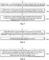
- Method 200 may include one or more operations, functions, or actions as illustrated by one or more of blocks 205-285. Although the blocks are illustrated in a sequential order, these blocks may also be performed in parallel, and/or in a different order than those described herein. Also, the various blocks may be combined into fewer blocks, divided into additional blocks, and/or removed based upon the desired implementation.
- each block may represent a module, a segment, or a portion of program code, which includes one or more instructions executable by a processor for implementing specific logical functions or steps in the process.
- the program code may be stored on any type of computer readable medium or data storage, for example, such as a storage device including a disk or hard drive. Further, the program code can be encoded on a computer-readable storage media in a machine-readable format, or on other non-transitory media or articles of manufacture.
- the computer readable medium may include non-transitory computer readable medium or memory, for example, such as computer-readable media that stores data for short periods of time like register memory, processor cache and Random Access Memory (RAM).
- the computer readable medium may also include non-transitory media, such as secondary or persistent long term storage, like read only memory (ROM), optical or magnetic disks, compact-disc read only memory (CD-ROM), for example.
- the computer readable media may also be any other volatile or non-volatile storage systems.
- the computer readable medium may be considered a tangible computer readable storage medium, for example.
- each block in Figure 3 may represent circuitry that is wired to perform the specific logical functions in the process.
- Alternative implementations are included within the scope of the examples of the present disclosure in which functions may be executed out of order from that shown or discussed, including substantially concurrent or in reverse order, depending on the functionality involved, as would be understood by those reasonably skilled in the art.
- Method 200 includes, at block 205, activating the first device 105, where the first device 105 has a working field 135 and has an operational path 125 configured to intersect a barrier 130.
- the second device 150 detects, via a proximity sensor 160 of the second device 150, a presence of an object 145 in a sensor zone 161 of the second device 150.
- a wireless signal is transmitted, via the second device 150, to the first device 105 indicating the presence of the object 145 in the sensor zone 161 of the second device 150.
- a first alert is issued, via at least one of the first device 105 and the second device 150, that indicates the presence of the object 145 in the sensor zone 161 of the second device 150.
- the second device 150 may receive a wireless signal from the first device 105 upon activation of the first device 105 as an initializing step. Performing an initialization step may permit the second device 150 to power the sensor 160 when the first device 105 is active and thereby conserve battery life of the second device 150.
- issuing the first alert includes at least one of activating a feedback mode of either the first device 105 or second device 150 or disabling at least one operative function of the first device 105.
- the feedback mode may include issuing a visual alert, an audible alert, or a tactile alert.
- activating a feedback mode of the first device 105 or second device 150 may help avoid contact between the object 145 and the first device 105.
- detecting, via the proximity sensor 160 of the second device 150, the presence of the object 145 in the sensor zone 161 of the second device 150 includes detecting the presence of the object 145 in the working field 135 of the first device 105, and issuing the first alert includes disabling at least one operative function of the first device 105.
- activating a feedback mode of the first device 105 and the second device 150 may not provide enough advance warning to an operator 140 or object 145 to avoid contact between the first device 105 and the object 145.
- disabling an operative function of the first device 105 such as drilling, sawing or emission of a laser or flame, may further reduce any injury or damage to the object 145 and help avoid contact between the first device 105 and the object 145.
- method 200 includes arranging the second device 150 in a non-line-of-sight position relative to the first device 105 such that the first device 105 and the second device 150 are arranged on opposite sides 131, 132 of the barrier 130. This arrangement permits increased situational awareness for one or both of an operator 140 of the first device 105 and an object 145 detected by the second device 150.
- method 200 includes, at block 230, determining, via the second device 150, a signal strength of the first device 105.
- the receiver 110 of the first device 105 is a transceiver that continuously emits a pilot signal.
- the transmitter 155 of the second device 150 is a transceiver that receives the pilot signal and the computing device 190 constantly determines the strength of the pilot signal by measuring the power level of the pilot signal.
- the computing device 190 also constantly compares the determined signal strength to a plurality of signal strength thresholds to adjust the alignment indicator 170, 175.
- a signal strength indicator is displayed on at least one of the first device 105 and the second device 150.
- the displayed signal strength indicator is based on the determined signal strength and the comparison to the plurality of signal strength thresholds.
- the signal strength indicator has the form of the alignment indicator 170 discussed above with respect to system 100.
- the second device 150 is positioned relative to the first device 105 based on the displayed signal strength indicator. Accordingly, the signal strength indicator improves the alignment of the second device 150 with the first device 105, when, for example, the second device 150 is arranged in a non-line-of-sight position relative to the first device 105.
- method 200 includes, at block 245, moving the first device 105 to a location remote from the second device 150. Then, at block 250, the second device 150 determines that a signal strength of the first device 105 is less than a predetermined signal strength threshold.
- the receiver 110 of the first device 105 is a transceiver that continuously emits a pilot signal.
- the transmitter 155 of the second device 150 is a transceiver that receives the pilot signal and the computing device 190 constantly determines the strength of the pilot signal by measuring the power level of the pilot signal. As the distance between the first device 105 and the second device 150 increases, the signal strength of the pilot signal from the first device 105 decreases and vice versa.
- the computing device 190 also constantly compares the determined signal strength of the first device 105 to the predetermined signal strength threshold to determine whether to execute instructions causing the second device 150 to relocate.
- the specific value of the predetermined signal strength threshold is application dependent and based on factors that include, but are not limited to, the size of the working field 135 and/or the size of the operational path 125 of the first device 105 and the thickness of the barrier 130.
- moving the second device 150 in a direction of the first device 105 in response to determining the signal strength of the first device 105 is less than the predetermined signal strength threshold, moving the second device 150 in a direction of the first device 105.
- a plurality of sensors capable of detecting signal strength may be placed in a spaced apart arrangement along a predetermined direction of travel.
- small advancements of the proximity sensor platform are made and the signal strength of the first device 105 is monitored during the advancements to determine the location of the first device 105 and to determine the direction of motion to relocate the second device 150.
- the second device 150 will detect this movement based on a decreased signal strength from the first device 105 that is less than the predetermined signal strength threshold.
- the computing device 190 may execute instructions causing an electric motor of the second device 150 to activate and drive wheels, rollers or other ambulatory mechanisms coupled to the second device such that movement is effected.
- moving the second device 150 in the direction of the first device 105 includes the second device 150 automatically moving along a guide-rail or a track 180 in response to sensor feedback detecting motion of the first device 105.
- the second device 150 may include additional proximity sensors that have sensor zones arranged facing potential directions of movement of the second device 150 to avoid contact with an object 145.
- the method 200 includes, at block 260, determining, via the second device 150, the signal strength of the first device 105.
- the second device 150 determines that the signal strength of the first device 105 meets the predetermined signal strength threshold and, at block 270, in response to determining the signal strength of the first device 105 meets or exceeds the predetermined signal strength threshold, movement of the second device 150 ceases.
- the computing device 190 may execute instructions causing an electric motor of the second device 150 to deactivate such that movement stops.
- the operations, functions, or actions as illustrated by blocks 245-270 permit automatic movement of the second device 150 without intervention by the operator 140 of the first device 105.
- method 200 includes, at block 275, determining that a signal strength of the second device 150 failed to be detected by the first device 105 for a predetermined amount of time.
- the first device 105 has a computing device 198 that has the same form and attributes as that of computing device 190 described with respect to Figure 10 below.
- the computing device 198 receives signals from the transmitter 155 of the second device 150 to determine signal strength for detection of the second device 150.
- the second device 150 continuously emits a pilot signal via the transmitter 155.
- the first device 105 receives the pilot signal and the computing device 198 constantly determines the strength of the pilot signal by measuring the power level of the pilot signal from the second device 150 and determines whether the signal strength has a non-zero value. If the measured signal strength is determined to have a zero value for a predetermined amount of time, this constitutes a failure to detect a signal of the second device 150. And, at block 280, a second alert is issued via the first device 105. In operation, a failure to detect a signal from the second device 150 may be an indication of a dead battery in the second device 150 or that the second device 150 was inadvertently moved away from the working field 135 of the first device 105. The second alert may take any of the forms and have any of the effects of the first alert discussed in detail above.
- method 200 includes, at block 285, in response to detecting, via the proximity sensor 160 of the second device 150, the presence of the object 145 in the sensor zone 161 of the second device 150, recording via a computing device 190 of the second device 150 or a network 199 at least one sensor-signal event.
- the sensor-signal event information may include, but is not limited to, a time-stamp, an identification of the specific proximity sensor 160 that detected the object 145 and a location of the proximity sensor 160 at the time of detection.
- the sensor-signal event information may further include an indication as to whether the object 145 was detected in the working field 135 of the first device 105.
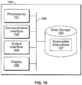
- FIG 10 is a block diagram illustrating an example of the computing device 190, according to an example implementation.
- the computing device 190 may be used to perform functions of methods shown in Figures 3-9 .
- the computing device 190 has a processor(s) 191, and also a communication interface 192, data storage 193, an output interface 194, and a display 195 each connected to a communication bus 196.
- the computing device 190 may also include hardware to enable communication within the computing device 190 and between the computing device 190 and other devices (not shown).
- the hardware may include transmitters, receivers, and antennas, for example.
- the communication interface 192 may be a wireless interface and/or one or more wired interfaces that allow for both short-range communication and long-range communication to one or more networks 199 or to one or more remote devices.
- Such wireless interfaces may provide for communication under one or more wireless communication protocols, such as Bluetooth, WiFi (e.g., an institute of electrical and electronic engineers (IEEE) 802.11 protocol), Long-Term Evolution (LTE), cellular communications, near-field communication (NFC), and/or other wireless communication protocols.
- Such wired interfaces may include Ethernet interface, a Universal Serial Bus (USB) interface, or similar interface to communicate via a wire, a twisted pair of wires, a coaxial cable, an optical link, a fiber-optic link, or other physical connection to a network 199.
- the communication interface 192 may be configured to receive input data from one or more devices, and may also be configured to send output data to other devices.
- the communication interface 192 may also include a user-input device, such as a keyboard or mouse, for example.
- the data storage 193 may include or take the form of one or more computer-readable storage media that can be read or accessed by the processor(s) 191.
- the computer-readable storage media can include volatile and/or non-volatile storage components, such as optical, magnetic, organic or other memory or disc storage, which can be integrated in whole or in part with the processor(s) 191.
- the data storage 193 is considered non-transitory computer readable media.
- the data storage 193 can be implemented using a single physical device (e.g., one optical, magnetic, organic or other memory or disc storage unit), while in other examples, the data storage 193 can be implemented using two or more physical devices.
- the data storage 193 thus is a non-transitory computer readable storage medium, and executable instructions 197 are stored thereon.
- the instructions 197 include computer executable code.
- the processor(s) 191 are caused to perform functions. Such functions include receiving signals from the proximity sensor 160 and determining whether to issue a first alert to activate one or more of the first alert indicators 115, 165 and the override switch 120, as well as receiving signals from the receiver 110 of the first device 105 and determining signal strength of the first device 105 for alignment with the second device 150.
- the processor(s) 191 may be a general-purpose processor or a special purpose processor (e.g., digital signal processors, application specific integrated circuits, etc.).
- the processor(s) 191 may receive inputs from the communication interface 192, and process the inputs to generate outputs that are stored in the data storage 193 and output to the display 195.
- the processor(s) 191 can be configured to execute the executable instructions 197 (e.g., computer-readable program instructions) that are stored in the data storage 193 and are executable to provide the functionality of the computing device 190 described herein.
- the output interface 194 outputs information to the display 195 or to other components as well.
- the output interface 194 may be similar to the communication interface 192 and can be a wireless interface (e.g., transmitter) or a wired interface as well.
- the output interface 194 may send information about detection of an object 145 to the first alert indicators 115, 165 and/or to the override switch 120, for example, and send information about signal strength of the first device 105 to the alignment indicator 175 of the second device 150, for example.
- the computing device 190 shown in Figure 10 may also be representative of the computing device 198, for example.
Landscapes
- Engineering & Computer Science (AREA)
- Mechanical Engineering (AREA)
- Computer Networks & Wireless Communication (AREA)
- Signal Processing (AREA)
- General Engineering & Computer Science (AREA)
- Manufacturing & Machinery (AREA)
- Physics & Mathematics (AREA)
- Business, Economics & Management (AREA)
- Emergency Management (AREA)
- General Physics & Mathematics (AREA)
- Aviation & Aerospace Engineering (AREA)
- Transportation (AREA)
- Emergency Alarm Devices (AREA)
- Quality & Reliability (AREA)
- Electromagnetism (AREA)
- Auxiliary Devices For Machine Tools (AREA)
- Alarm Systems (AREA)
- Electrical Discharge Machining, Electrochemical Machining, And Combined Machining (AREA)
- Spinning Or Twisting Of Yarns (AREA)
Claims (15)
- Verfahren, aufweisend:Aktivieren (205) einer ersten Vorrichtung (105), wobei die erste Vorrichtung ein Arbeitsfeld (135) aufweist, wobei die erste Vorrichtung einen Betriebspfad (125), der dazu ausgebildet ist, eine Barriere (130) zu schneiden, aufweist;Erfassen (210), über einen Näherungssensor (160) einer zweiten Vorrichtung (150), einer Anwesenheit eines Objekts in einer Sensorzone (161) der zweiten Vorrichtung;Übertragen (215), über die zweite Vorrichtung (150), eines drahtlosen Signals, das die Anwesenheit des Objekts in der Sensorzone (161) der zweiten Vorrichtung indiziert, an die erste Vorrichtung;Ausgeben (220) eines ersten Alarms, über mindestens eine der ersten Vorrichtung und der zweiten Vorrichtung, der die Anwesenheit des Objekts in der Sensorzone (161) der zweiten Vorrichtung indiziert; undBestimmen (275), dass eine Signalstärke der zweiten Vorrichtung (150) von der ersten Vorrichtung (105) für eine vorbestimmte Zeitdauer nicht erfasst wurde; undAusgeben (280) eines zweiten Alarms über die erste Vorrichtung.
- Verfahren nach Anspruch 1, wobei das Erfassen, über den Näherungssensor (160) der zweiten Vorrichtung, der Anwesenheit des Objekts in der Sensorzone (161) der zweiten Vorrichtung (150) das Erfassen der Anwesenheit des Objekts in dem Arbeitsfeld der ersten Vorrichtung (105) aufweist, und wobei das Ausgeben des ersten Alarms das Deaktivieren mindestens einer Betriebsfunktion der ersten Vorrichtung (105) aufweist.
- Verfahren nach Anspruch 1 oder 2, des Weiteren aufweisend:Bestimmen (230), über die zweite Vorrichtung (150), einer Signalstärke der ersten Vorrichtung (105);Anzeigen (235) eines Signalstärkeindikators (170) auf mindestens einer der ersten Vorrichtung und der zweiten Vorrichtung, wobei der angezeigte Signalstärkeindikator auf der bestimmten Signalstärke basiert; undPositionieren (240) der zweiten Vorrichtung (150) relativ zu der ersten Vorrichtung basierend auf dem angezeigten Signalstärkeindikator.
- Verfahren nach Anspruch 3, des Weiteren aufweisend:Bewegen (245) der ersten Vorrichtung (105) an einen von der zweiten Vorrichtung (150) entfernten Ort;Bestimmen (250), über die zweite Vorrichtung, dass eine Signalstärke der ersten Vorrichtung geringer ist als ein vorbestimmter Signalstärke-Grenzwert; undals Reaktion auf das Bestimmen, dass die Signalstärke der ersten Vorrichtung geringer ist als der vorherbestimmte Signalstärke-Grenzwert, Bewegen (255) der zweiten Vorrichtung in eine Richtung der ersten Vorrichtung; undwobei das Bewegen der zweiten Vorrichtung (150) in die Richtung der ersten Vorrichtung (105) das automatische Bewegen der zweiten Vorrichtung entlang einer Führungsschiene oder einer Spur als Reaktion auf das Feedback des Sensors (160) aufweist.
- Verfahren nach Anspruch 4, des Weiteren aufweisend:Bestimmen (260) der Signalstärke der ersten Vorrichtung (105) über die zweite Vorrichtung (150);Bestimmen (265), über die zweite Vorrichtung, ob die Signalstärke der ersten Vorrichtung den vorbestimmten Signalstärke-Grenzwert erreicht oder überschreitet; undals Reaktion auf das Bestimmen, ob die Signalstärke der ersten Vorrichtung den vorbestimmten Signalstärke-Grenzwert erreicht oder überschreitet, Beenden (270) der Bewegung des zweiten Geräts (270).
- Verfahren nach einem der Ansprüche 1 bis 5, des Weiteren aufweisend das Anordnen (225) der zweiten Vorrichtung (150) in einer Nicht-Sichtlinien-Position relativ zu der ersten Vorrichtung (105), so dass die erste Vorrichtung und die zweite Vorrichtung auf gegenüberliegenden Seiten (131) der Barriere (130) angeordnet sind.
- Verfahren nach einem der Ansprüche 1 bis 6, wobei das Ausgeben des ersten Alarms (115) das Ausgeben eines visuellen Alarms, eines akustischen Alarms oder eines taktilen Alarms aufweist.
- Verfahren nach einem der Ansprüche 1 bis 7, wobei das Ausgeben des ersten Alarms (115) mindestens entweder das Aktivieren eines Feedback-Modus entweder der ersten Vorrichtung oder der zweiten Vorrichtung oder das Deaktivieren mindestens einer Betriebsfunktion der ersten Vorrichtung (105) aufweist.
- Verfahren nach einem der Ansprüche 1 bis 8, des Weiteren aufweisend:
als Reaktion auf das Erfassen der Anwesenheit des Objekts in der Sensorzone (161) der zweiten Vorrichtung (150) über den Näherungssensor (160) der zweiten Vorrichtung, Aufzeichnen (285) mindestens eines Sensorsignalereignisses über eine Rechenvorrichtung (190) der zweiten Vorrichtung oder ein Netzwerk. - System, aufweisend:eine erste Vorrichtung (105) mit einem Empfänger (110) und mindestens einem von einem ersten Alarmindikator (115) und einem Override-Schalter (120); undmindestens eine zweite Vorrichtung (150) mit einem Transmitter (155) und einem Näherungssensor (160), wobei der Näherungssensor ausgebildet ist zur Kommunikation mit dem Transmitter der zweiten Vorrichtung, wobei die zweite Vorrichtung dazu ausgebildet ist, mindestens ein drahtloses Signal an den Empfänger der ersten Vorrichtung (105) zu senden, um entweder den ersten Alarmindikator (115) oder den Override-Schalter (120) in Reaktion darauf, dass der Näherungssensor ein Objekt innerhalb einer Sensorzone (161) der zweiten Vorrichtung (150) erfasst, zu aktivieren,einen zweiten Alarmindikator (185), der mit der ersten Vorrichtung (105) gekoppelt ist und dazu ausgebildet ist, als Reaktion auf eine Bestimmung, dass eine Signalstärke der zweiten Vorrichtung (150) für eine vorbestimmte Zeitdauer nicht erfasst wurde, sich zu aktivieren.
- System nach Anspruch 10, wobei mindestens eine der ersten Vorrichtung (105) und der zweiten Vorrichtung (150) eine Ausrichtungsindikator (170) aufweist, der dazu ausgebildet ist, eine von der zweiten Vorrichtung empfangene Signalstärke der ersten Vorrichtung zu indizieren, wobei der Ausrichtungsindikator (170) eine Mehrzahl von LEDs, eine mehrfarbige LED oder ein Licht, das mit unterschiedlichen Raten basierend auf der Signalstärke des ersten Geräts blinkt, aufweist (105).
- System nach Anspruch 10 oder 11, wobei der Näherungssensor (160) mindestens einen von einem optischen Sensor, einem Infrarotsensor, einem Ultraschallsensor, einem taktilen Sensor, einem Kontaktsensor, einem kapazitiven Sensor, einem laserbasierten Sensor, einer Einweglichtschranke, einem kamerabasierten Sensor und einem Bewegungssensor aufweist.
- System nach Anspruch 10 bis 12, wobei der erste Alarmindikator (115) eine Steuerung, die dazu ausgebildet ist, mindestens ein visuelles, akustisches oder taktiles Feedback zu bewirken, aufweist.
- System nach einem der Ansprüche 10 bis 13, wobei die zweite Vorrichtung (150) des Weiteren eine Rechenvorrichtung (190) aufweist, die dazu ausgebildet ist, die zweite Vorrichtung als Reaktion auf eine Bestimmung durch die Rechenvorrichtung, dass ein von der ersten Vorrichtung (105) empfangenes Signal eine Signalstärke aufweist, die niedriger ist als ein vorbestimmter Signalstärke-Grenzwert, automatisch zu bewegen.
- System nach einem der Ansprüche 10 bis 14, wobei die zweite Vorrichtung (150) in einer Nicht-Sichtlinien-Position relativ zu der ersten Vorrichtung (105) angeordnet ist, so dass die erste Vorrichtung und die zweite Vorrichtung auf gegenüberliegenden Seiten einer Barriere (130) angeordnet sind.
Applications Claiming Priority (2)
| Application Number | Priority Date | Filing Date | Title |
|---|---|---|---|
| US15/593,520 US10127792B1 (en) | 2017-05-12 | 2017-05-12 | Safety system for operations having a working field on an opposite side of a barrier from a device |
| EP18169846.5A EP3403750B1 (de) | 2017-05-12 | 2018-04-27 | Sicherheitssystem für betriebe mit einem arbeitsfeld auf der gegenüberliegenden seite einer schranke einer vorrichtung |
Related Parent Applications (2)
| Application Number | Title | Priority Date | Filing Date |
|---|---|---|---|
| EP18169846.5A Division-Into EP3403750B1 (de) | 2017-05-12 | 2018-04-27 | Sicherheitssystem für betriebe mit einem arbeitsfeld auf der gegenüberliegenden seite einer schranke einer vorrichtung |
| EP18169846.5A Division EP3403750B1 (de) | 2017-05-12 | 2018-04-27 | Sicherheitssystem für betriebe mit einem arbeitsfeld auf der gegenüberliegenden seite einer schranke einer vorrichtung |
Publications (2)
| Publication Number | Publication Date |
|---|---|
| EP3689517A1 EP3689517A1 (de) | 2020-08-05 |
| EP3689517B1 true EP3689517B1 (de) | 2021-10-27 |
Family
ID=62089633
Family Applications (2)
| Application Number | Title | Priority Date | Filing Date |
|---|---|---|---|
| EP20162611.6A Active EP3689517B1 (de) | 2017-05-12 | 2018-04-27 | Sicherheitssystem für betriebe mit einem arbeitsfeld auf der gegenüberliegenden seite einer schranke einer vorrichtung |
| EP18169846.5A Active EP3403750B1 (de) | 2017-05-12 | 2018-04-27 | Sicherheitssystem für betriebe mit einem arbeitsfeld auf der gegenüberliegenden seite einer schranke einer vorrichtung |
Family Applications After (1)
| Application Number | Title | Priority Date | Filing Date |
|---|---|---|---|
| EP18169846.5A Active EP3403750B1 (de) | 2017-05-12 | 2018-04-27 | Sicherheitssystem für betriebe mit einem arbeitsfeld auf der gegenüberliegenden seite einer schranke einer vorrichtung |
Country Status (5)
| Country | Link |
|---|---|
| US (2) | US10127792B1 (de) |
| EP (2) | EP3689517B1 (de) |
| JP (1) | JP6774983B2 (de) |
| CN (1) | CN108877159B (de) |
| CA (2) | CA3001845C (de) |
Families Citing this family (8)
| Publication number | Priority date | Publication date | Assignee | Title |
|---|---|---|---|---|
| US10805869B2 (en) * | 2017-08-25 | 2020-10-13 | Qualcomm Incorporated | Techniques and apparatuses for search, measurement, and icon display in new radio non-standalone mode |
| DE102019102004B3 (de) * | 2019-01-28 | 2020-06-10 | Pilz Gmbh & Co. Kg | Verbessertes Zugangsabsicherungssystem zum Absichern einer Maschine oder Anlage |
| US10795342B1 (en) * | 2019-04-01 | 2020-10-06 | The Boeing Company | Proximity detection in assembly environments having machinery |
| US10841736B1 (en) | 2019-12-18 | 2020-11-17 | Tile, Inc. | Notifications in a tracking device environment |
| CN112382046A (zh) * | 2020-10-29 | 2021-02-19 | 光大生物能源(含山)有限公司 | 料场人车交叉作业电子安防预警系统及方法 |
| DE112022003872T5 (de) * | 2021-09-10 | 2024-07-04 | Milwaukee Electric Tool Corporation | Systeme und verfahren zur mehrkanalkommunikation kraftbetriebener werkzeuge |
| WO2023039201A1 (en) * | 2021-09-10 | 2023-03-16 | Milwaukee Electric Tool Corporation | Systems and methods for tool location tracking |
| CN121697869A (zh) * | 2026-02-11 | 2026-03-20 | 天津飞悦航空科技股份有限公司 | 一种飞机机翼脉动生产用的可移动工装系统及接口方法 |
Family Cites Families (20)
| Publication number | Priority date | Publication date | Assignee | Title |
|---|---|---|---|---|
| JPH07291539A (ja) * | 1994-04-25 | 1995-11-07 | Hataya Seisakusho:Kk | コード巻取り装置 |
| US6357101B1 (en) * | 2000-03-09 | 2002-03-19 | The Boeing Company | Method for installing fasteners in a workpiece |
| US20080196910A1 (en) * | 2000-06-20 | 2008-08-21 | Radle Patrick J | Electrical sensing device modules for attachment to power tools and drills |
| US20050141997A1 (en) * | 2003-12-01 | 2005-06-30 | Rast Rodger H. | Ceiling fan proximity safety apparatus |
| US7194358B2 (en) | 2004-02-25 | 2007-03-20 | The Boeing Company | Lift collision avoidance system |
| WO2007041295A2 (en) * | 2005-09-30 | 2007-04-12 | Irobot Corporation | Companion robot for personal interaction |
| TWM334975U (en) * | 2007-11-27 | 2008-06-21 | Universal Scient Ind Co Ltd | Detector for detecting the obstacle behind a door |
| US20170113316A1 (en) * | 2010-06-21 | 2017-04-27 | William Alexander Barr | Locating Device for Use with Power Tools |
| US9030332B2 (en) * | 2011-06-27 | 2015-05-12 | Motion Metrics International Corp. | Method and apparatus for generating an indication of an object within an operating ambit of heavy loading equipment |
| US20170206756A1 (en) * | 2013-04-23 | 2017-07-20 | Monica BASTIDAS | Safety drop cloth |
| US10482742B2 (en) * | 2013-09-24 | 2019-11-19 | John R. Brooks | Universal, proximity wireless system for potential victim to disengage dangerous devices |
| US9466188B2 (en) * | 2014-12-24 | 2016-10-11 | Immersion Corporation | Systems and methods for haptically-enabled alarms |
| US20160188977A1 (en) * | 2014-12-24 | 2016-06-30 | Irobot Corporation | Mobile Security Robot |
| JP2016142110A (ja) * | 2015-02-05 | 2016-08-08 | アズビル株式会社 | ドアの衝突防止装置 |
| US10210722B2 (en) * | 2015-06-15 | 2019-02-19 | Immersion Corporation | Haptic notification communication system |
| ITUB20151930A1 (it) * | 2015-07-03 | 2017-01-03 | Soilmec Spa | Sistema e metodo di sicurezza per la rilevazione di una condizione di rischio in una regione situata in prossimita' di una macchina operatrice, quale una macchina di perforazione o simile. |
| US9981385B2 (en) | 2015-10-12 | 2018-05-29 | The Boeing Company | Dynamic automation work zone safety system |
| US10818197B2 (en) * | 2016-03-10 | 2020-10-27 | Husqvarna Ab | Teaching mode for construction devices |
| WO2017165757A1 (en) * | 2016-03-24 | 2017-09-28 | Warwick Mills, Inc. | Wearable safety warning and measurement system |
| CN105804606A (zh) * | 2016-04-22 | 2016-07-27 | 成都聚智工业设计有限公司 | 新型智能安防门 |
-
2017
- 2017-05-12 US US15/593,520 patent/US10127792B1/en not_active Ceased
-
2018
- 2018-04-16 CA CA3001845A patent/CA3001845C/en active Active
- 2018-04-16 CA CA3168194A patent/CA3168194C/en active Active
- 2018-04-27 EP EP20162611.6A patent/EP3689517B1/de active Active
- 2018-04-27 EP EP18169846.5A patent/EP3403750B1/de active Active
- 2018-05-11 CN CN201810447153.9A patent/CN108877159B/zh active Active
- 2018-05-11 JP JP2018091928A patent/JP6774983B2/ja active Active
-
2019
- 2019-02-27 US US16/286,818 patent/USRE48257E1/en active Active
Also Published As
| Publication number | Publication date |
|---|---|
| CA3001845A1 (en) | 2018-11-12 |
| JP2019003623A (ja) | 2019-01-10 |
| CA3168194A1 (en) | 2018-11-12 |
| EP3403750B1 (de) | 2020-04-22 |
| CN108877159B (zh) | 2021-08-20 |
| CN108877159A (zh) | 2018-11-23 |
| CA3001845C (en) | 2023-04-11 |
| EP3689517A1 (de) | 2020-08-05 |
| CA3168194C (en) | 2023-10-24 |
| JP6774983B2 (ja) | 2020-10-28 |
| USRE48257E1 (en) | 2020-10-13 |
| EP3403750A1 (de) | 2018-11-21 |
| US10127792B1 (en) | 2018-11-13 |
| US20180330596A1 (en) | 2018-11-15 |
Similar Documents
| Publication | Publication Date | Title |
|---|---|---|
| EP3403750B1 (de) | Sicherheitssystem für betriebe mit einem arbeitsfeld auf der gegenüberliegenden seite einer schranke einer vorrichtung | |
| US11380205B2 (en) | Proximity detection system and method and collision avoidance system and method using proximity detection | |
| JP7226923B2 (ja) | モジュール型の安全性モニタリング・警告システム、及びそれを使用するための方法 | |
| CA2844335C (en) | Proximity detection system with concurrent rf and magnetic fields | |
| JP7361441B2 (ja) | 作業車両の安全システム | |
| CN105405248B (zh) | 大型机械设备安全距离警报系统及报警方法 | |
| US20190084796A1 (en) | Restricted access area safety system | |
| JP3964405B2 (ja) | 警報装置 | |
| KR20170055370A (ko) | 이격 거리별 능동 알에프아이디 태그를 구비하는 중장비 안전 경보 시스템 | |
| JP3189644U (ja) | 緊急遠隔通報システム | |
| KR101533614B1 (ko) | 중장비용 충돌경고장치 | |
| US20240127640A1 (en) | Proximity detection system cap lamp | |
| US20230267778A1 (en) | Vehicle to vehicle collision avoidance system and method | |
| AU2024266106A1 (en) | Vehicle, cap lamp system and methods for collision avoidance | |
| KR20230122746A (ko) | 안전 경보 제공 시스템, 안전 경보 제공 장치 및 안전 경보 제공 애플리케이션 | |
| KR20180056901A (ko) | 엘리베이터 끼임 방지 안전시스템 |
Legal Events
| Date | Code | Title | Description |
|---|---|---|---|
| PUAI | Public reference made under article 153(3) epc to a published international application that has entered the european phase |
Free format text: ORIGINAL CODE: 0009012 |
|
| STAA | Information on the status of an ep patent application or granted ep patent |
Free format text: STATUS: THE APPLICATION HAS BEEN PUBLISHED |
|
| AC | Divisional application: reference to earlier application |
Ref document number: 3403750 Country of ref document: EP Kind code of ref document: P |
|
| AK | Designated contracting states |
Kind code of ref document: A1 Designated state(s): AL AT BE BG CH CY CZ DE DK EE ES FI FR GB GR HR HU IE IS IT LI LT LU LV MC MK MT NL NO PL PT RO RS SE SI SK SM TR |
|
| STAA | Information on the status of an ep patent application or granted ep patent |
Free format text: STATUS: REQUEST FOR EXAMINATION WAS MADE |
|
| 17P | Request for examination filed |
Effective date: 20210108 |
|
| RBV | Designated contracting states (corrected) |
Designated state(s): AL AT BE BG CH CY CZ DE DK EE ES FI FR GB GR HR HU IE IS IT LI LT LU LV MC MK MT NL NO PL PT RO RS SE SI SK SM TR |
|
| RIC1 | Information provided on ipc code assigned before grant |
Ipc: B64F 5/10 20170101ALI20210331BHEP Ipc: F16P 3/14 20060101ALI20210331BHEP Ipc: B25F 5/00 20060101ALI20210331BHEP Ipc: B23B 49/00 20060101AFI20210331BHEP |
|
| GRAP | Despatch of communication of intention to grant a patent |
Free format text: ORIGINAL CODE: EPIDOSNIGR1 |
|
| STAA | Information on the status of an ep patent application or granted ep patent |
Free format text: STATUS: GRANT OF PATENT IS INTENDED |
|
| INTG | Intention to grant announced |
Effective date: 20210512 |
|
| GRAS | Grant fee paid |
Free format text: ORIGINAL CODE: EPIDOSNIGR3 |
|
| GRAA | (expected) grant |
Free format text: ORIGINAL CODE: 0009210 |
|
| STAA | Information on the status of an ep patent application or granted ep patent |
Free format text: STATUS: THE PATENT HAS BEEN GRANTED |
|
| AC | Divisional application: reference to earlier application |
Ref document number: 3403750 Country of ref document: EP Kind code of ref document: P |
|
| AK | Designated contracting states |
Kind code of ref document: B1 Designated state(s): AL AT BE BG CH CY CZ DE DK EE ES FI FR GB GR HR HU IE IS IT LI LT LU LV MC MK MT NL NO PL PT RO RS SE SI SK SM TR |
|
| REG | Reference to a national code |
Ref country code: GB Ref legal event code: FG4D |
|
| REG | Reference to a national code |
Ref country code: CH Ref legal event code: EP |
|
| REG | Reference to a national code |
Ref country code: DE Ref legal event code: R096 Ref document number: 602018025933 Country of ref document: DE |
|
| REG | Reference to a national code |
Ref country code: AT Ref legal event code: REF Ref document number: 1441357 Country of ref document: AT Kind code of ref document: T Effective date: 20211115 |
|
| REG | Reference to a national code |
Ref country code: IE Ref legal event code: FG4D |
|
| REG | Reference to a national code |
Ref country code: LT Ref legal event code: MG9D |
|
| REG | Reference to a national code |
Ref country code: NL Ref legal event code: MP Effective date: 20211027 |
|
| REG | Reference to a national code |
Ref country code: AT Ref legal event code: MK05 Ref document number: 1441357 Country of ref document: AT Kind code of ref document: T Effective date: 20211027 |
|
| PG25 | Lapsed in a contracting state [announced via postgrant information from national office to epo] |
Ref country code: RS Free format text: LAPSE BECAUSE OF FAILURE TO SUBMIT A TRANSLATION OF THE DESCRIPTION OR TO PAY THE FEE WITHIN THE PRESCRIBED TIME-LIMIT Effective date: 20211027 Ref country code: LT Free format text: LAPSE BECAUSE OF FAILURE TO SUBMIT A TRANSLATION OF THE DESCRIPTION OR TO PAY THE FEE WITHIN THE PRESCRIBED TIME-LIMIT Effective date: 20211027 Ref country code: FI Free format text: LAPSE BECAUSE OF FAILURE TO SUBMIT A TRANSLATION OF THE DESCRIPTION OR TO PAY THE FEE WITHIN THE PRESCRIBED TIME-LIMIT Effective date: 20211027 Ref country code: BG Free format text: LAPSE BECAUSE OF FAILURE TO SUBMIT A TRANSLATION OF THE DESCRIPTION OR TO PAY THE FEE WITHIN THE PRESCRIBED TIME-LIMIT Effective date: 20220127 Ref country code: AT Free format text: LAPSE BECAUSE OF FAILURE TO SUBMIT A TRANSLATION OF THE DESCRIPTION OR TO PAY THE FEE WITHIN THE PRESCRIBED TIME-LIMIT Effective date: 20211027 |
|
| PG25 | Lapsed in a contracting state [announced via postgrant information from national office to epo] |
Ref country code: IS Free format text: LAPSE BECAUSE OF FAILURE TO SUBMIT A TRANSLATION OF THE DESCRIPTION OR TO PAY THE FEE WITHIN THE PRESCRIBED TIME-LIMIT Effective date: 20220227 Ref country code: SE Free format text: LAPSE BECAUSE OF FAILURE TO SUBMIT A TRANSLATION OF THE DESCRIPTION OR TO PAY THE FEE WITHIN THE PRESCRIBED TIME-LIMIT Effective date: 20211027 Ref country code: PT Free format text: LAPSE BECAUSE OF FAILURE TO SUBMIT A TRANSLATION OF THE DESCRIPTION OR TO PAY THE FEE WITHIN THE PRESCRIBED TIME-LIMIT Effective date: 20220228 Ref country code: PL Free format text: LAPSE BECAUSE OF FAILURE TO SUBMIT A TRANSLATION OF THE DESCRIPTION OR TO PAY THE FEE WITHIN THE PRESCRIBED TIME-LIMIT Effective date: 20211027 Ref country code: NO Free format text: LAPSE BECAUSE OF FAILURE TO SUBMIT A TRANSLATION OF THE DESCRIPTION OR TO PAY THE FEE WITHIN THE PRESCRIBED TIME-LIMIT Effective date: 20220127 Ref country code: NL Free format text: LAPSE BECAUSE OF FAILURE TO SUBMIT A TRANSLATION OF THE DESCRIPTION OR TO PAY THE FEE WITHIN THE PRESCRIBED TIME-LIMIT Effective date: 20211027 Ref country code: LV Free format text: LAPSE BECAUSE OF FAILURE TO SUBMIT A TRANSLATION OF THE DESCRIPTION OR TO PAY THE FEE WITHIN THE PRESCRIBED TIME-LIMIT Effective date: 20211027 Ref country code: HR Free format text: LAPSE BECAUSE OF FAILURE TO SUBMIT A TRANSLATION OF THE DESCRIPTION OR TO PAY THE FEE WITHIN THE PRESCRIBED TIME-LIMIT Effective date: 20211027 Ref country code: GR Free format text: LAPSE BECAUSE OF FAILURE TO SUBMIT A TRANSLATION OF THE DESCRIPTION OR TO PAY THE FEE WITHIN THE PRESCRIBED TIME-LIMIT Effective date: 20220128 Ref country code: ES Free format text: LAPSE BECAUSE OF FAILURE TO SUBMIT A TRANSLATION OF THE DESCRIPTION OR TO PAY THE FEE WITHIN THE PRESCRIBED TIME-LIMIT Effective date: 20211027 |
|
| REG | Reference to a national code |
Ref country code: DE Ref legal event code: R097 Ref document number: 602018025933 Country of ref document: DE |
|
| PG25 | Lapsed in a contracting state [announced via postgrant information from national office to epo] |
Ref country code: SM Free format text: LAPSE BECAUSE OF FAILURE TO SUBMIT A TRANSLATION OF THE DESCRIPTION OR TO PAY THE FEE WITHIN THE PRESCRIBED TIME-LIMIT Effective date: 20211027 Ref country code: SK Free format text: LAPSE BECAUSE OF FAILURE TO SUBMIT A TRANSLATION OF THE DESCRIPTION OR TO PAY THE FEE WITHIN THE PRESCRIBED TIME-LIMIT Effective date: 20211027 Ref country code: RO Free format text: LAPSE BECAUSE OF FAILURE TO SUBMIT A TRANSLATION OF THE DESCRIPTION OR TO PAY THE FEE WITHIN THE PRESCRIBED TIME-LIMIT Effective date: 20211027 Ref country code: EE Free format text: LAPSE BECAUSE OF FAILURE TO SUBMIT A TRANSLATION OF THE DESCRIPTION OR TO PAY THE FEE WITHIN THE PRESCRIBED TIME-LIMIT Effective date: 20211027 Ref country code: DK Free format text: LAPSE BECAUSE OF FAILURE TO SUBMIT A TRANSLATION OF THE DESCRIPTION OR TO PAY THE FEE WITHIN THE PRESCRIBED TIME-LIMIT Effective date: 20211027 Ref country code: CZ Free format text: LAPSE BECAUSE OF FAILURE TO SUBMIT A TRANSLATION OF THE DESCRIPTION OR TO PAY THE FEE WITHIN THE PRESCRIBED TIME-LIMIT Effective date: 20211027 |
|
| PLBE | No opposition filed within time limit |
Free format text: ORIGINAL CODE: 0009261 |
|
| STAA | Information on the status of an ep patent application or granted ep patent |
Free format text: STATUS: NO OPPOSITION FILED WITHIN TIME LIMIT |
|
| 26N | No opposition filed |
Effective date: 20220728 |
|
| PG25 | Lapsed in a contracting state [announced via postgrant information from national office to epo] |
Ref country code: AL Free format text: LAPSE BECAUSE OF FAILURE TO SUBMIT A TRANSLATION OF THE DESCRIPTION OR TO PAY THE FEE WITHIN THE PRESCRIBED TIME-LIMIT Effective date: 20211027 |
|
| PG25 | Lapsed in a contracting state [announced via postgrant information from national office to epo] |
Ref country code: SI Free format text: LAPSE BECAUSE OF FAILURE TO SUBMIT A TRANSLATION OF THE DESCRIPTION OR TO PAY THE FEE WITHIN THE PRESCRIBED TIME-LIMIT Effective date: 20211027 |
|
| REG | Reference to a national code |
Ref country code: CH Ref legal event code: PL |
|
| REG | Reference to a national code |
Ref country code: BE Ref legal event code: MM Effective date: 20220430 |
|
| PG25 | Lapsed in a contracting state [announced via postgrant information from national office to epo] |
Ref country code: MC Free format text: LAPSE BECAUSE OF FAILURE TO SUBMIT A TRANSLATION OF THE DESCRIPTION OR TO PAY THE FEE WITHIN THE PRESCRIBED TIME-LIMIT Effective date: 20211027 Ref country code: LU Free format text: LAPSE BECAUSE OF NON-PAYMENT OF DUE FEES Effective date: 20220427 Ref country code: LI Free format text: LAPSE BECAUSE OF NON-PAYMENT OF DUE FEES Effective date: 20220430 Ref country code: CH Free format text: LAPSE BECAUSE OF NON-PAYMENT OF DUE FEES Effective date: 20220430 |
|
| PG25 | Lapsed in a contracting state [announced via postgrant information from national office to epo] |
Ref country code: BE Free format text: LAPSE BECAUSE OF NON-PAYMENT OF DUE FEES Effective date: 20220430 |
|
| PG25 | Lapsed in a contracting state [announced via postgrant information from national office to epo] |
Ref country code: IE Free format text: LAPSE BECAUSE OF NON-PAYMENT OF DUE FEES Effective date: 20220427 |
|
| PG25 | Lapsed in a contracting state [announced via postgrant information from national office to epo] |
Ref country code: IT Free format text: LAPSE BECAUSE OF FAILURE TO SUBMIT A TRANSLATION OF THE DESCRIPTION OR TO PAY THE FEE WITHIN THE PRESCRIBED TIME-LIMIT Effective date: 20211027 |
|
| P01 | Opt-out of the competence of the unified patent court (upc) registered |
Effective date: 20230516 |
|
| PG25 | Lapsed in a contracting state [announced via postgrant information from national office to epo] |
Ref country code: MK Free format text: LAPSE BECAUSE OF FAILURE TO SUBMIT A TRANSLATION OF THE DESCRIPTION OR TO PAY THE FEE WITHIN THE PRESCRIBED TIME-LIMIT Effective date: 20211027 Ref country code: CY Free format text: LAPSE BECAUSE OF FAILURE TO SUBMIT A TRANSLATION OF THE DESCRIPTION OR TO PAY THE FEE WITHIN THE PRESCRIBED TIME-LIMIT Effective date: 20211027 |
|
| PG25 | Lapsed in a contracting state [announced via postgrant information from national office to epo] |
Ref country code: HU Free format text: LAPSE BECAUSE OF FAILURE TO SUBMIT A TRANSLATION OF THE DESCRIPTION OR TO PAY THE FEE WITHIN THE PRESCRIBED TIME-LIMIT; INVALID AB INITIO Effective date: 20180427 |
|
| PG25 | Lapsed in a contracting state [announced via postgrant information from national office to epo] |
Ref country code: TR Free format text: LAPSE BECAUSE OF FAILURE TO SUBMIT A TRANSLATION OF THE DESCRIPTION OR TO PAY THE FEE WITHIN THE PRESCRIBED TIME-LIMIT Effective date: 20211027 |
|
| PG25 | Lapsed in a contracting state [announced via postgrant information from national office to epo] |
Ref country code: MT Free format text: LAPSE BECAUSE OF FAILURE TO SUBMIT A TRANSLATION OF THE DESCRIPTION OR TO PAY THE FEE WITHIN THE PRESCRIBED TIME-LIMIT Effective date: 20211027 |
|
| PGFP | Annual fee paid to national office [announced via postgrant information from national office to epo] |
Ref country code: DE Payment date: 20250429 Year of fee payment: 8 |
|
| PGFP | Annual fee paid to national office [announced via postgrant information from national office to epo] |
Ref country code: GB Payment date: 20250428 Year of fee payment: 8 |
|
| PGFP | Annual fee paid to national office [announced via postgrant information from national office to epo] |
Ref country code: FR Payment date: 20250425 Year of fee payment: 8 |