EP3689397B1 - Corps de seringue, seringue et dispositif d'injection permettant d'injecter un milieu à haute viscosité - Google Patents
Corps de seringue, seringue et dispositif d'injection permettant d'injecter un milieu à haute viscosité Download PDFInfo
- Publication number
- EP3689397B1 EP3689397B1 EP19154910.4A EP19154910A EP3689397B1 EP 3689397 B1 EP3689397 B1 EP 3689397B1 EP 19154910 A EP19154910 A EP 19154910A EP 3689397 B1 EP3689397 B1 EP 3689397B1
- Authority
- EP
- European Patent Office
- Prior art keywords
- syringe body
- syringe
- injection device
- chamber
- highly viscous
- Prior art date
- Legal status (The legal status is an assumption and is not a legal conclusion. Google has not performed a legal analysis and makes no representation as to the accuracy of the status listed.)
- Active
Links
Images

Classifications
-
- A—HUMAN NECESSITIES
- A61—MEDICAL OR VETERINARY SCIENCE; HYGIENE
- A61M—DEVICES FOR INTRODUCING MEDIA INTO, OR ONTO, THE BODY; DEVICES FOR TRANSDUCING BODY MEDIA OR FOR TAKING MEDIA FROM THE BODY; DEVICES FOR PRODUCING OR ENDING SLEEP OR STUPOR
- A61M5/00—Devices for bringing media into the body in a subcutaneous, intra-vascular or intramuscular way; Accessories therefor, e.g. filling or cleaning devices, arm-rests
- A61M5/178—Syringes
- A61M5/31—Details
- A61M5/3129—Syringe barrels
- A61M5/3134—Syringe barrels characterised by constructional features of the distal end, i.e. end closest to the tip of the needle cannula
-
- A—HUMAN NECESSITIES
- A61—MEDICAL OR VETERINARY SCIENCE; HYGIENE
- A61K—PREPARATIONS FOR MEDICAL, DENTAL OR TOILETRY PURPOSES
- A61K31/00—Medicinal preparations containing organic active ingredients
- A61K31/70—Carbohydrates; Sugars; Derivatives thereof
- A61K31/715—Polysaccharides, i.e. having more than five saccharide radicals attached to each other by glycosidic linkages; Derivatives thereof, e.g. ethers, esters
- A61K31/726—Glycosaminoglycans, i.e. mucopolysaccharides
- A61K31/728—Hyaluronic acid
-
- A—HUMAN NECESSITIES
- A61—MEDICAL OR VETERINARY SCIENCE; HYGIENE
- A61M—DEVICES FOR INTRODUCING MEDIA INTO, OR ONTO, THE BODY; DEVICES FOR TRANSDUCING BODY MEDIA OR FOR TAKING MEDIA FROM THE BODY; DEVICES FOR PRODUCING OR ENDING SLEEP OR STUPOR
- A61M5/00—Devices for bringing media into the body in a subcutaneous, intra-vascular or intramuscular way; Accessories therefor, e.g. filling or cleaning devices, arm-rests
- A61M5/178—Syringes
- A61M5/31—Details
- A61M5/3129—Syringe barrels
- A61M5/3137—Specially designed finger grip means, e.g. for easy manipulation of the syringe rod
-
- A—HUMAN NECESSITIES
- A61—MEDICAL OR VETERINARY SCIENCE; HYGIENE
- A61M—DEVICES FOR INTRODUCING MEDIA INTO, OR ONTO, THE BODY; DEVICES FOR TRANSDUCING BODY MEDIA OR FOR TAKING MEDIA FROM THE BODY; DEVICES FOR PRODUCING OR ENDING SLEEP OR STUPOR
- A61M5/00—Devices for bringing media into the body in a subcutaneous, intra-vascular or intramuscular way; Accessories therefor, e.g. filling or cleaning devices, arm-rests
- A61M5/178—Syringes
- A61M5/31—Details
- A61M5/315—Pistons; Piston-rods; Guiding, blocking or restricting the movement of the rod or piston; Appliances on the rod for facilitating dosing ; Dosing mechanisms
- A61M5/31511—Piston or piston-rod constructions, e.g. connection of piston with piston-rod
-
- A—HUMAN NECESSITIES
- A61—MEDICAL OR VETERINARY SCIENCE; HYGIENE
- A61M—DEVICES FOR INTRODUCING MEDIA INTO, OR ONTO, THE BODY; DEVICES FOR TRANSDUCING BODY MEDIA OR FOR TAKING MEDIA FROM THE BODY; DEVICES FOR PRODUCING OR ENDING SLEEP OR STUPOR
- A61M5/00—Devices for bringing media into the body in a subcutaneous, intra-vascular or intramuscular way; Accessories therefor, e.g. filling or cleaning devices, arm-rests
- A61M5/178—Syringes
- A61M5/31—Details
- A61M5/32—Needles; Details of needles pertaining to their connection with syringe or hub; Accessories for bringing the needle into, or holding the needle on, the body; Devices for protection of needles
- A61M5/3293—Needles; Details of needles pertaining to their connection with syringe or hub; Accessories for bringing the needle into, or holding the needle on, the body; Devices for protection of needles characterised by features of the needle hub
-
- A—HUMAN NECESSITIES
- A61—MEDICAL OR VETERINARY SCIENCE; HYGIENE
- A61M—DEVICES FOR INTRODUCING MEDIA INTO, OR ONTO, THE BODY; DEVICES FOR TRANSDUCING BODY MEDIA OR FOR TAKING MEDIA FROM THE BODY; DEVICES FOR PRODUCING OR ENDING SLEEP OR STUPOR
- A61M5/00—Devices for bringing media into the body in a subcutaneous, intra-vascular or intramuscular way; Accessories therefor, e.g. filling or cleaning devices, arm-rests
- A61M5/178—Syringes
- A61M5/31—Details
- A61M5/32—Needles; Details of needles pertaining to their connection with syringe or hub; Accessories for bringing the needle into, or holding the needle on, the body; Devices for protection of needles
- A61M5/34—Constructions for connecting the needle, e.g. to syringe nozzle or needle hub
- A61M5/343—Connection of needle cannula to needle hub, or directly to syringe nozzle without a needle hub
-
- A—HUMAN NECESSITIES
- A61—MEDICAL OR VETERINARY SCIENCE; HYGIENE
- A61M—DEVICES FOR INTRODUCING MEDIA INTO, OR ONTO, THE BODY; DEVICES FOR TRANSDUCING BODY MEDIA OR FOR TAKING MEDIA FROM THE BODY; DEVICES FOR PRODUCING OR ENDING SLEEP OR STUPOR
- A61M5/00—Devices for bringing media into the body in a subcutaneous, intra-vascular or intramuscular way; Accessories therefor, e.g. filling or cleaning devices, arm-rests
- A61M5/178—Syringes
- A61M5/31—Details
- A61M5/32—Needles; Details of needles pertaining to their connection with syringe or hub; Accessories for bringing the needle into, or holding the needle on, the body; Devices for protection of needles
- A61M5/34—Constructions for connecting the needle, e.g. to syringe nozzle or needle hub
- A61M5/347—Constructions for connecting the needle, e.g. to syringe nozzle or needle hub rotatable, e.g. bayonet or screw
-
- A—HUMAN NECESSITIES
- A61—MEDICAL OR VETERINARY SCIENCE; HYGIENE
- A61M—DEVICES FOR INTRODUCING MEDIA INTO, OR ONTO, THE BODY; DEVICES FOR TRANSDUCING BODY MEDIA OR FOR TAKING MEDIA FROM THE BODY; DEVICES FOR PRODUCING OR ENDING SLEEP OR STUPOR
- A61M5/00—Devices for bringing media into the body in a subcutaneous, intra-vascular or intramuscular way; Accessories therefor, e.g. filling or cleaning devices, arm-rests
- A61M5/178—Syringes
- A61M5/31—Details
- A61M5/315—Pistons; Piston-rods; Guiding, blocking or restricting the movement of the rod or piston; Appliances on the rod for facilitating dosing ; Dosing mechanisms
- A61M5/31511—Piston or piston-rod constructions, e.g. connection of piston with piston-rod
- A61M2005/3152—Piston or piston-rod constructions, e.g. connection of piston with piston-rod including gearings to multiply or attenuate the piston displacing force
Definitions
- the present invention relates to an injection device for injecting a highly viscous medium.
- the injection device can be used for injecting or administering highly viscous pharmaceutical media.
- Syringes are used, for example, in the medical and cosmetic fields and are used to inject a medium contained in the syringe into a patient's body.
- dermal fillers are injected beneath the patient's skin during a cosmetic skin treatment.
- Highly viscous media are typically used in cosmetic applications.
- Media contained in syringes can include various forms of fluids, pasty or liquid substances, and mixtures.
- the document US 2010/152679 A1 discloses a syringe that can be connected to a needle assembly for injecting a viscous liquid. To achieve a sufficiently strong connection between the syringe body and the needle assembly and to prevent detachment, the document proposes US 2010/152679 A1 proposes to provide a thread of a connecting section between the syringe and the needle assembly with a pitch of 3 mm.
- needles with a very thin gauge are preferred. This is especially true for applications on the patient's face.
- an object of the present invention is to overcome the disadvantages of the prior art.
- an object of the invention is to provide an injection device that enables the use of needles with a small cannula thickness for injecting highly viscous media.
- One aspect of the invention relates to an injection device for injecting or applying a highly viscous medium, comprising a syringe with a syringe body and a needle assembly.
- the highly viscous medium is characterized by a storage modulus G' of at least 30 Pa and at most 150 Pa, in particular at least 50 Pa and at most 100 Pa, or at least 70 and at most 90 Pa.
- the loss factor tan ⁇ can be between 0.2 and 0.8, in particular between 0.3 and 0.6 or between 0.4 and 0.5. These can be, for example, hyaluronic acid fillers.
- the viscosity can be measured using a plate-on-plate measuring system at 25°C and an air pressure of 1013.25 hPa (e.g., rheometer from Anton Paar MCR 302), particularly at a frequency of 1 Hz.
- the measurement can be carried out, for example, using the method according to ISO standard 6721-10-2015-09.
- the syringe body comprises a distal end section and a proximal end section.
- the syringe body is hollow cylindrical and forms a chamber for containing the highly viscous medium.
- the proximal end section has an opening through which a piston rod assembly can be or is inserted into the chamber.
- the piston rod assembly is displaceable in the chamber in the direction of a longitudinal chamber axis and is slidably guided in the syringe body.
- a Luer-Lock connector is formed on the distal end portion of the syringe body, comprising an outer cone with a further opening for dispensing the highly viscous medium and a sleeve-shaped portion with an internal thread.
- the Luer-Lock connector forms part of a Luer-Lock connection system and is designed to interact with a Luer-Lock connector counterpart formed on a needle assembly.
- the outer cone can also be described as a conical nozzle projecting beyond a distal end of the syringe body, through which the highly viscous medium can be discharged from the chamber.
- the outer cone also forms part of the Luer-Lock connection system and also interacts with a complementary counterpart of the needle assembly.
- the outer cone and the sleeve-shaped portion surrounding it are arranged coaxially with one another.
- the Luer-Lock connector of the syringe body can be designed and dimensioned, in particular, within the framework of ISO Standard 80369-7:2016-12-01. This allows the syringe body according to the invention to be used with a variety of different needle arrangements standardized in the area of the Luer-Lock connection.
- the syringe body has a minimum NPO resistance of between 90 N and 105 N, preferably between 95 N and 103.5 N, preferably between 98 N and 102 N.
- NPO stands for "needle pop off” and refers to the sudden detachment or popping off of a needle assembly from a syringe body, in particular a needle assembly connected to the syringe body via a Luer lock connection.
- the needle assembly Under high pressure (triggered by applying force to the syringe body via the piston rod assembly), the needle assembly begins to rotate and detach from the syringe body at high speed, i.e., an inner cone of the needle assembly, complementary to the outer cone of the syringe body, detaches.
- the NPO minimum resistance (“needle pop-off" minimum resistance) specifies a threshold value of the force applied to a plunger rod assembly inserted into and operatively connected to the syringe barrel during the test procedure described below.
- the NPO minimum resistance is defined as a force below which no more than 1.8% of the tested syringe barrels experience a needle pop-off. At least 56 measurements of syringe barrels of the same configuration and design are required to obtain a meaningful result for the NPO minimum resistance.
- the test procedure for measuring NPO resistance requires that the syringe barrel to be tested is placed vertically in a testing machine and held in the area of the proximal end of the syringe barrel.
- the testing machine used is a universal testing machine from "TesT", model “TesT 106.2 kN”. This or a comparable universal testing machine must be used for the test procedure.
- the syringe body to be tested is connected via the Luer-Lock connector to a needle assembly, which is screwed onto the distal end section of the syringe body using a Luer-Lock connector counterpart with a torque of 12 Ncm to establish the Luer-Lock connection.
- the described test procedure is to be performed with the needle assembly "TSK STERiJECT Hypodermic Needle", Ref.: PRC-30013I, 30 G x 1/2, or a comparable needle assembly.
- the needle assembly used for the test procedure comprises an inner cone as a Luer-Lock connector counterpart and two fins arranged on the outer circumference of a needle hub of the needle assembly.
- the needle assembly used for the test procedure comprises a cannula or hollow needle with a thickness of 30 G and a length of 13 mm (30 G x 1 ⁇ 2).
- the cannula is available for testing purposes
- To perform the test procedure flatten the syringe barrel with a hammer, thereby sealing it.
- a dry Luer-Lock connection must be established by screwing the needle assembly onto the syringe barrel before a highly viscous medium is subsequently filled into the chamber.
- the test procedure must be performed using non-steam-sterilized components (syringe barrel, needle assembly, plunger rod assembly).
- a highly viscous medium with a storage modulus G' of approximately 84.5 Pa and a loss factor tan ⁇ of approximately 0.48 must be selected.
- the viscosity can be measured using a plate-on-plate measuring system at 25°C and an air pressure of 1013.25 hPa (e.g., a rheometer from Anton Paar MCR 302), particularly at a frequency of 1 Hz.
- the measurement can be carried out, for example, using the method according to ISO standard 6721-10-2015-09.
- the syringe barrel to be tested is completely filled with the highly viscous material as intended.
- a piston rod assembly is inserted into the syringe barrel at the beginning of the test procedure and is operatively connected to it.
- syringe barrel and piston rod assembly are still in an initial position, i.e., in a non-actuated position, at the beginning of the test procedure.
- a standard piston rod arrangement intended for the particular syringe barrel to be tested must be used.
- a standard piston of the FM257 type e.g., from the manufacturer Daetwyler
- a force is applied perpendicularly to the proximal end of the piston rod assembly via a test piston on the testing machine.
- the test piston moves at a constant test speed of 12.6 mm/min towards the distal end section of the syringe body, continuously increasing the force acting on the piston rod assembly up to a maximum of 420 N.
- the test piston is displaced up to a distance of 15 mm.
- the applied force is detected by a force sensor with a sampling rate of 200 Hz.
- the test piston continues to move or the applied force is increased until leakage and/or NPO occurs or until the maximum force of 420 N is reached.
- the test is stopped, i.e.
- leakage and/or NPO is detected, when the measured force suddenly drops by at least 30%.
- the applied force at the time of occurrence of leakage and/or NPO is documented and linked to the information whether leakage and/or NPO occurred at this force. From the documented measurement results, the above-described NPO minimum resistance and the average NPO resistance can then be determined.
- the leakage examined here is the leakage between the syringe body and the needle assembly caused by the applied force and the resulting pressure. In other words, the force can be determined at which a leak occurs between the syringe body and the needle arrangement in the area of the Luer-Lock connection, the highly viscous medium escapes unintentionally.
- a smaller needle or cannula diameter e.g., over 30 G means less pain for the patient than larger needle or cannula diameters (e.g., the 27 G diameter conventionally used with highly viscous media), but at the same time requires a greater application of force than a larger needle or cannula diameter to dispense the highly viscous medium.
- the above values for the NPO minimum resistance according to the invention take into account the knowledge that, when used as intended, male users can operate a syringe or injection device with an average maximum force (maximum finger force) of 95 N.
- Female users can operate a syringe or injection device with an average maximum force (maximum finger force) of 64 N when used as intended.
- the NPO minimum resistance defined above thus represents an optimal design of the syringe body structure, which ensures safe injection of a highly viscous medium with a very thin cannula and is nevertheless not oversized.
- the syringe body can have an average NPO resistance of at least 100 N, preferably at least 105 N, preferably at least 110 N, more preferably at least 115 N, even more preferably at least 117 N.
- the average NPO resistance can be between 100 N and 120 N, preferably between 105 N and 120 N, preferably between 110 N and 120 N, more preferably between 115 N and 117 N.
- the average NPO resistance indicates the average force that must be applied to a plunger rod assembly inserted into and operatively connected to the syringe barrel during the test procedure described above for a needle pop-off to occur. Again, at least 56 measurements of syringe barrels of the same configuration and design are required to obtain a meaningful result for the average NPO resistance.
- the syringe body may have a minimum leakage resistance of at least 100 N.
- the syringe body can have a minimum leakage resistance of more than 105 N, preferably more than 117.5 N, more preferably more than 125 N.
- the syringe body can have a minimum leakage resistance of between 100 N and 130 N, preferably between 105 N and 120 N, preferably between 110 N and 115 N.
- the syringe body can have an average leakage resistance of at least 115 N, preferably at least 120 N, preferably at least 123 N, more preferably at least 125 N, even more preferably at least 127 N.
- the average leakage resistance can be between 110 N and 135 N, preferably between 115 N and 130 N, preferably between 120 N and 130 N, more preferably between 125 N and 130 N.
- the minimum leakage resistance indicates a threshold value of the force applied to a plunger rod assembly inserted into and operatively connected to the syringe barrel during the test procedure described above.
- the minimum leakage resistance is defined as the threshold value below which a leak occurs in less than 1.8% of the tested syringe barrels. At least 56 measurements of syringe barrels of the same configuration and design are required to obtain a meaningful result for the minimum leakage resistance.
- the average leakage resistance indicates the average force that must be applied to a plunger rod assembly inserted into and operatively connected to the syringe barrel during the test procedure described above for leakage to occur. At least 56 measurements of syringe barrels of the same configuration and design are required to obtain a meaningful result for the average leakage resistance.
- the internal thread of the Luer-Lock connector can have an internal diameter of a maximum of 7.15 mm or a maximum of 7.12 mm.
- the internal diameter can preferably be at least 7.05 mm or at least 7.08 mm.
- the internal diameter is between 7.05 mm and 7.15 mm, preferably between 7.08 mm and 7.12 mm, preferably a maximum of 7.1 mm.
- the internal diameter describes the smallest internal diameter of the sleeve-shaped end section, i.e., measured from thread crest to opposite thread crest of the internal thread.
- An internal diameter with this dimension can have a positive effect on a sufficiently tight connection between the syringe body and a needle assembly connected thereto and thus
- the setting of the minimum NPO resistance and the average NPO resistance can be advantageously influenced. The same applies to the minimum leakage resistance and the average leakage resistance.
- the internal thread at the crest of the thread profile can have a width of at least 0.44 mm or at least 0.46 mm.
- the width is a maximum of 0.52 mm or a maximum of 0.50 mm.
- the width can be between 0.44 mm and 0.52 mm, preferably between 0.46 mm and 0.50 mm, preferably 0.48 mm.
- the internal thread at the base of the thread profile can have a width of at least 0.85 mm or at least 0.875 mm.
- the width is a maximum of 0.95 mm or a maximum of 0.925 mm.
- the width can be between 0.85 mm and 0.95 mm, preferably between 0.875 mm and 0.925 mm, preferably 0.9 mm.
- the internal thread can have an angle of between 22.5° and 27.5° on both sides of the thread profile, in particular an angle of 24° to 26° or approximately 25°.
- the angle can be described as the angle enclosed between a line orthogonal to the longitudinal axis of the syringe body and intersecting the thread profile and the flank of the thread profile.
- the contact area of the threaded connection i.e., the contact area between the internal thread of the syringe body and a complementary external thread of an associated needle assembly, can be adapted. This can improve the Luer Lock connection with the associated needle assembly and have a beneficial effect on setting the minimum NPO resistance and the average NPO resistance. The same applies to the minimum leakage resistance and the average leakage resistance.
- a distal end face of the outer cone which closes the outer cone and is provided with the further opening, can protrude beyond a distal collar of the sleeve-shaped section by a distance of at least 2.1 mm or at least 2.2 mm. In one embodiment, this distance is a maximum of 2.5 mm or a maximum of 2.4 mm. In a preferred embodiment, the distal end face of the outer cone protrudes beyond a distal collar of the sleeve-shaped section by a distance of 2.1 mm to 2.5 mm, preferably 2.2 mm to 2.4 mm, preferably 2.3 mm.
- This structural adaptation can have a beneficial effect on setting the minimum NPO resistance and the average NPO resistance. The same applies to the minimum leakage resistance and the average leakage resistance.
- the syringe body comprises an inner circumferential surface with a chamfer at the proximal end portion, which tapers the inner circumferential surface from the proximal end portion toward the distal end portion.
- the inner circumferential surface tapers conically in the region of the chamfer toward the distal end portion.
- the chamfer can simplify the insertion of the piston rod assembly, more precisely the piston, into the chamber of the syringe body.
- the chamfer has a length of between 1.2 mm and 1.8 mm, preferably from 1.4 mm to 1.6 mm, preferably of approximately 1.5 mm, viewed in the direction of the longitudinal axis of the syringe body.
- the chamfer encloses an angle of at least 13°, preferably of at least 14°, preferably of at least 15° with the longitudinal axis.
- a distance of at least 9 mm to a maximum of 10 mm, or approximately 9.5 mm, can be provided between the proximal end of the syringe and a proximal end of the piston of the piston rod assembly when the syringe is fully filled and not actuated.
- the syringe body can have a maximum total length of 80 mm and a maximum chamber inner diameter of 5 mm, wherein a volume of at least 1 ml can be accommodated in the syringe body. More precisely, a volume of at least 1 ml can be accommodated in the chamber and an adjoining chamber section formed by the outer cone.
- the total length can be measured from an end face of the syringe body delimiting the proximal end section to an end face of the syringe body delimiting the distal end section, i.e. the end face of the outer cone.
- the chamber inner diameter can be measured over the entire length of the chamber be constant throughout.
- the chamber and the chamber section together can hold a volume of 1.073 ml to allow for 2% overfilling and the inclusion of a 1 mm air bubble in the chamber.
- the volume that can be absorbed is not the same as the total volume formed by the entire chamber and the chamber section.
- the chamber must also be able to accommodate part of the piston rod assembly even in a non-actuated position and support it stably.
- the piston of the piston rod assembly must already be accommodated in the syringe body at a sufficient distance from the proximal end of the syringe body in a non-actuated position. For example, a distance of 9.5 mm can be provided between the proximal end of the syringe and a proximal end of the piston of the piston rod assembly.
- the syringe body may preferably be designed and dimensioned within and in accordance with ISO standard 11040-6:2012-04-01.
- the syringe body can have a maximum total length of 60 mm and a maximum chamber inner diameter of 4.65 mm, wherein a volume of at least 0.5 ml can be accommodated in the chamber and the chamber section together.
- the syringe body can have a maximum total length of 71 mm and a maximum chamber inner diameter of 5 mm, wherein a volume of at least 0.8 ml can be accommodated in the chamber and the chamber section together.
- the syringe body can have a maximum total length of 95 mm and a maximum chamber inner diameter of 6.45 mm, wherein the chamber and the chamber section together can hold a volume of at least 2.25 ml.
- the syringe body can have a maximum total length of 117 mm and a maximum chamber inner diameter of 6.45 mm, wherein the chamber and the chamber section together can hold a volume of at least 2.8 ml.
- the syringe body can have a maximum total length of 56 mm and a maximum chamber inner diameter of 12.2 mm, wherein the chamber and the chamber section together can hold a volume of at least 2.8 ml.
- the syringe body can have a maximum total length of 58 mm and a maximum chamber inner diameter of 12.2 mm, wherein a volume of at least 3.0 ml can be accommodated in the chamber and the chamber section together.
- the syringe body can have a maximum total length of 115 mm and an inner chamber diameter of maximum 8.75 mm, whereby the chamber and the chamber section together can hold a volume of at least 5 ml.
- the values described above can be maximum dimensions or exact dimensions.
- a small inner chamber diameter has a positive effect on the application of a highly viscous liquid by applying finger force to the syringe or injection device.
- care must be taken to ensure that the overall length of the syringe body, which also determines the overall length of the associated piston rod assembly, is not too large to ensure handling.
- the embodiments described above represent exemplary embodiments that indicate advantageous combinations of overall length and inner diameter for different syringe body volumes.
- the syringe body can have a wall thickness of at least 1.7 mm, preferably at least 1.8 mm, preferably at least 2.0 mm, and more preferably at least 2.2 mm, at least in the region of the chamber. Forming such a wall thickness can positively influence the dimensional stability of the syringe body during use and thereby reduce mechanical failure of the syringe body.
- the specified values represent an optimized geometry with regard to the ratio between the inner and outer diameters.
- the syringe body may have an outer diameter of between 5 mm and 15 mm, in particular between 7.5 mm and 12.5 mm, or between 8.4 mm and 10 mm, in particular of approximately 9.4 mm.
- the syringe body can be designed such that it has an extrusion force of less than 40 N when a standard piston is displaced at 10 mm/min in the chamber towards the distal end section.
- the syringe body can be designed such that it has an extrusion force of less than 75 N when a standard piston is displaced at 50 mm/min in the chamber towards the distal end section.
- the syringe body can be designed such that it has an extrusion force of less than 100 N when a standard piston is displaced at 100 mm/min in the chamber towards the distal end section.
- the above values refer to the dispensing of a highly viscous medium with a storage modulus G' of approximately 84.5 Pa and a loss factor tan ⁇ of approximately 0.48.
- the viscosity can be measured with a plate-plate measuring system at 25°C and an air pressure of 1013.25 hPa (e.g. Rheometer Company: Anton Paar MCR 302), in particular with a frequency of 1 Hz.
- the measurement can be carried out, for example, using the method according to ISO standard 6721-10-2015-09.
- the extrusion force describes the force with which the medium is extruded from a Cannula of a needle assembly connected to the syringe barrel.
- High-viscosity media generally require higher extrusion forces than low-viscosity media.
- a test assembly with a needle assembly that includes a 30 G needle with a thickness of 13 mm and a length of 13 mm, i.e., a 30 G x 1/2 needle assembly, specifically the "TSK HYPODERMIC NEEDLE" needle assembly, Ref.: HPC-30013I-320, 30 G x 1/2.
- the cannula is open during this test procedure, allowing the high-viscosity medium to exit the cannula.
- the needle assembly includes a thread as a Luer-Lock connector counterpart (in contrast to the needle assembly with fins).
- a syringe barrel with such comparatively low extrusion forces for high-viscosity media requires less force from the user and enables improved dosing accuracy.
- such syringe bodies allow the use of needle assemblies with cannulas of low thickness, i.e. a thickness of 30 G or more.
- the syringe body can be made of a plastic material that preferably has a Young's modulus between 2800 MPa and 3300 MPa, in particular between 2900 MPa and 3200 MPa (1 mm/min, ISO 527 Parts 1 and 2).
- the plastic material can have a tensile strength (5 mm/min, ISO 527 Parts 1 and 2) between 58 MPa and 65 MPa, in particular in the range of 60 MPa to 63 MPa.
- the plastic material can have a water absorption of less than 0.01% (ISO 62).
- the plastic material can have a ball indentation hardness between 180 and 195 N/mm 2 (30-s value at a load of 961 N according to ISO 2039 Part 1).
- the plastic material may have a heat deflection temperature between 120 and 180 °C (HDT/B 0.45 MPa, ISO 75 Parts 1 and 2).
- the linear thermal expansion coefficient of the plastic material may be 6.0 ⁇ 10 -4 K -1 (ISO 11 359 Parts 1 and 2).
- the elongation at break of the plastic material may be in the range of 2.5 to 2.7% (ISO 527 Parts 1 and 2).
- the impact strength of the plastic material may be approximately 15 kJ/m 2 (ISO 179/1eU) and/or the notched impact strength may be in the range of 1.6 kJ/m 2 to 1.8 kJ/m 2 (ISO 179/1eA).
- the syringe body can comprise a flange at its proximal end portion.
- the flange can form a grip for supporting the index and middle fingers of a user when using the syringe body, or can be provided with such a grip.
- the syringe for injecting a highly viscous medium with a syringe body of the type described above comprises a piston rod assembly.
- the piston rod assembly comprises a piston rod and a piston attached to a distal end of the piston rod.
- the piston is connected to the proximal end of the piston rod via the opening.
- the end section of the syringe body is received in the chamber and guided in a displaceable manner.
- the piston can, for example, comprise three sealing lips.
- the syringe can comprise a highly viscous medium contained in the chamber of the syringe body.
- the highly viscous medium is characterized by a storage modulus G' of at least 30 Pa and at most 150 Pa, in particular at least 50 Pa and at most 100 Pa, or at least 70 and at most 90 Pa.
- the loss factor tan ⁇ can be between 0.2 and 0.8, in particular between 0.3 and 0.6 or between 0.4 and 0.5.
- the viscosity can be measured using a plate-on-plate measuring system at 25°C and an air pressure of 1013.25 hPa (e.g., rheometer from Anton Paar MCR 302), in particular at a frequency of 1 Hz.
- the measurement can be carried out, for example, using the method according to ISO standard 6721-10-2015-09.
- the syringe may contain hyaluronic acid fillers and/or other cosmetic compositions contained in the chamber of the syringe body.
- the syringe can have a gripping length between 6 cm and 12 cm, in particular between 7.5 cm and 8 cm.
- the gripping length refers to the length between the proximal end of the syringe body and a proximal end of the plunger rod assembly.
- the plunger rod assembly can be provided with a handle at the proximal end.
- the needle assembly comprises a needle hub and a cannula, wherein the needle hub comprises a Luer-Lock connector counterpart complementary to the Luer-Lock connector of the syringe body for establishing the Luer-Lock connection between the syringe body and the needle assembly.
- the needle hub comprises an inner cone complementary to the outer cone of the syringe body and preferably an external thread complementary to the internal thread of the syringe body.
- the needle hub can comprise two fins arranged on the outer circumference of the needle hub.
- the needle assembly may comprise a cannula having a thickness of at least 30 G (gauge), preferably at least 31 G, preferably at least 32 G, preferably at least 33 G, more preferably at least 34 G, even more preferably at least 35 G.
- the cannula may have a length of at least 10 mm, preferably at least 11 mm, preferably at least 12 mm, more preferably at least 13 mm. Alternatively, the cannula may have a length of 25 mm or more.
- the needle hub of the needle assembly may comprise an inner cone having a length along a longitudinal axis of the needle assembly between 3 mm and 7 mm, preferably between 5.5 mm and 6.5 mm, preferably of about 6.1 mm.
- the injection device may comprise the needle assembly "TSK HYPODERMIC NEEDLE", Ref.: HPC-30013I-320, 30 G x 1 ⁇ 2 or a comparable needle assembly.
- the injection device may comprise the needle assembly "TSK STERiJECT Hypodermic Needle", Ref.: PRC-30013I, 30 G x 1 ⁇ 2 or a comparable needle assembly.
- the syringe body may be constructed from a plastic material comprising or consisting of a cycloolefin copolymer (COC) and/or a cycloolefin polymer (COP).
- COC cycloolefin copolymer
- COP cycloolefin polymer
- the plastic material may comprise one or more additives, wherein an additive may preferably be a dye.
- the invention also relates to a cosmetic method comprising applying a highly viscous cosmetic preparation using an injection device described herein.
- the highly viscous cosmetic preparation is characterized by a storage modulus G' of at least 30 Pa and at most 150 Pa, in particular at least 50 Pa and at most 100 Pa, or at least 70 and at most 90 Pa.
- the loss factor tan ⁇ can be between 0.2 and 0.8, in particular between 0.3 and 0.6 or between 0.4 and 0.5.
- the viscosity can be measured using a plate-plate measuring system at 25°C and an air pressure of 1013.25 hPa (e.g., rheometer from Anton Paar MCR 302), in particular at a frequency of 1 Hz.
- the measurement can be carried out, for example, using the method according to ISO standard 6721-10-2015-09.
- Application may involve injecting the cosmetic preparation into an organism to be treated.
- the preparation is applied to an application site on a human organism.
- the application may be a subcutaneous injection.
- the application site may be a human face or a portion thereof.
- FIG. 1 shows various perspective views of an injection device 10 according to an embodiment of the invention as exploded views and in the assembled state.
- the injection device 10 comprises a syringe body 12, a piston rod assembly 14, and a needle assembly 16.
- the elongated syringe body 12 is hollow-cylindrical and forms a chamber for receiving a medium, in particular a highly viscous medium.
- the syringe body 12 has a distal end portion 18 and a proximal end portion 20.
- the proximal end portion 20 has an opening through which the piston rod assembly 14 can be inserted into the chamber (see views on the right side in Fig. 1 ).
- a Luer-Lock connector 22 is formed, which is described in detail with reference to Fig. 2
- the proximal end portion 20 of the syringe body 12 is provided with a flange 24 which serves as a handle for supporting the index finger and middle finger of a user when using the syringe body 12.
- the piston rod assembly 14 comprises a piston rod 26 and a piston 28, which in the exemplary embodiment is made of an elastic material and has three sealing lips.
- the piston 28 is attached to a distal end of the piston rod 26 and can be slidably guided over an inner circumferential surface of the chamber of the syringe body 12 and can be displaced in the direction of a chamber longitudinal axis.
- the piston rod assembly 14 comprises a handle 30, via which force can be exerted on the injection device 10 by means of the user's thumb.
- the needle assembly 16 comprises a needle hub 32 and a cannula 34 in the form of a hollow needle.
- the cannula 34 has a thickness of at least 30 G and a length of 13 mm.
- the needle hub 32 has a Luer-Lock connector counterpart 36, which can establish a tight Luer-Lock connection with the Luer-Lock connector 22 of the syringe body 12 in order to connect the syringe body 12 to the needle assembly 14.
- the Luer-Lock connector counterpart 36 more precisely the needle hub 32, in the illustrated embodiment comprises an inner cone and two fins formed on an outer circumferential surface of a proximal end of the needle hub 32.
- the needle hub can be provided with an external thread or an external thread portion instead of fins. Using such an external thread design, an even more secure Luer-Lock connection can be realized.
- the syringe body 12 In order to close the syringe body 12, for example during transport, it can be closed in the area of the Luer-Lock connector 22 by means of the Figure 1
- the syringe body 12 may be closed by the lid 38 shown.
- This lid 38 is complementary to the Luer lock connector 22 of the syringe body 12.
- the lid 38 is removed from the syringe body 12 before the needle assembly 16 is connected to the syringe body 12.
- the injection device 10 can be moved from a non-actuated position to an actuated position by displacing the piston 28 within the chamber from the proximal end portion 20 toward the distal end portion 18. This allows a highly viscous medium, such as hyaluronic acid, held in the chamber to be injected through the cannula 34 beneath the skin surface of a patient.
- a highly viscous medium such as hyaluronic acid
- the syringe body 12 is made of cycloolefin polymer (COP) or cycloolefin copolymer (COC).
- COP cycloolefin polymer
- COC cycloolefin copolymer
- FIG 2 shows an enlarged sectional view of the Luer-Lock connector 22 of the syringe body 12.
- the Luer-Lock connector 22 comprises an outer cone 40 with a further opening 42 for dispensing the highly viscous medium contained in the chamber. As can be seen in Figures 1 and 2, the outer cone 42 protrudes as a conically shaped nozzle beyond a distal end of the syringe body 12.
- the Luer-Lock connector 22 also comprises a sleeve-shaped portion 44 provided with an internal thread 46.
- the outer cone 40 is surrounded by the sleeve-shaped portion 44, wherein the outer cone 40 and the sleeve-shaped portion 44 are arranged coaxially with one another.
- the internal thread 46 has a smallest internal diameter I 1 of 7.1 mm, measured from thread crest 50 to the opposite thread crest 50' of the internal thread 46.
- the largest internal diameter I 2 measured from thread root 54 to the opposite thread root 54' of the internal thread 46, is 8.0 mm in the illustrated embodiment.
- the outer diameter A H of the sleeve-shaped portion 44 is 10.0 mm. Accordingly, the sleeve-shaped portion 44 has a wall thickness of 1 mm.
- the internal thread 46 has a width B K of 0.48 mm at the crest 50 of the thread profile. Furthermore, the internal thread 46 has a width B G of 0.9 mm at the base 54 of the thread profile. The internal thread has an angle ⁇ and ⁇ of 25° on both sides of the thread profile. A thread profile designed with these dimensions serves to optimally define the common contact surface with the complementary external thread of the associated needle arrangement. This can contribute to the targeted adjustment of the NPO minimum resistance, the average NPO resistance, the minimum leakage resistance, and the average leakage resistance.
- the outer cone 40 comprises a distal end face 56 in which the further opening 42 is formed.
- the distal end face 56 protrudes a distance A of 2.3 mm beyond a distal collar 58 of the sleeve-shaped portion 44, viewed in the direction of the longitudinal axis L of the syringe body 12.
- the distal end face 56 of the outer cone 40 is spaced from an underside of the first complete thread profile facing away from the end face 56 by a distance B of 3.1 mm.
- the outer cone 40 has a total cone length C of 8.9 mm.
- the Figure 3 shown parameters B K , B G , ⁇ and ⁇ of the thread profile, the The smallest inner diameter I 1 and/or the distance A can be provided with these dimensions for syringe bodies with different chamber volumes in order to achieve optimal values for the minimum NPO resistance, for the average NPO resistance, for the minimum leakage resistance and for the average leakage resistance of the syringe body 12.
- FIG 4 is a sectional view of the syringe body 12 with a piston rod arrangement 14 accommodated therein, wherein the piston rod arrangement 14 is not shown in full for reasons of clarity.
- the syringe body 12 of the exemplary embodiment shown has a total length L SK of 80.0 mm.
- the total length L SK is made up of the length of a section of the syringe body forming the chamber and the total cone length C of the outer cone 40.
- the inner chamber diameter I K of the chamber is 5 mm in the example shown. This means that a medium, in particular a highly viscous medium, with a volume V of 1073 mm 3 can be accommodated in the chamber of the syringe body 12 and the adjoining chamber section formed by the outer cone 40.
- This absorbable volume V results from the considerations and resulting design measures according to which the syringe body 12 should provide a highly viscous medium with a volume of 1 ml.
- the chamber must allow for overfilling of 2% and the inclusion of an air bubble 1 mm long (see length s).
- the chamber must be able to accommodate part of the piston rod assembly even in a non-actuated position and support it stably.
- a proximal end of the piston 28 of the piston rod assembly 14 should already be spaced a distance u of 9.5 mm from the proximal end of the syringe body 12 in a non-actuated position. Furthermore, a third (proximal) sealing lip of the piston 28 of the piston rod assembly 14 is spaced a distance o of 9.5 mm from a chamfer 60 of the syringe body 12 in this non-actuated position.
- the piston 28 has, for example, a length t of 6.9 mm.
- the chamfer 60 is formed on the inner peripheral surface of the proximal end portion 20 of the syringe body 12.
- the chamfer 60 tapers the inner peripheral surface of the syringe body 12 from the proximal end portion 20 toward the distal end portion 18.
- the chamfer 60 is in Figure 5 shown enlarged. It has a length w of 1.5 mm viewed in the direction of a longitudinal axis L of the syringe body 12 and forms an angle ⁇ of 15° with the longitudinal axis L. A radius R of 0.5 mm is provided in a transition region of the chamfer 60 to the proximal end of the syringe body 12.
- the syringe body 12 of the illustrated embodiment has a wall thickness of 2.2 mm in the area of the chamber, which provides sufficient stability against breakage of the syringe body.
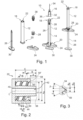
- Figure 6 shows a diagram with test results for a syringe body according to the invention, showing various measured resistances of the syringe body against NPO and leakage.
- the underlying tests were carried out with the syringe body 12 of the Figures 1 to 5
- the various measurements from the illustrated series (56 individual measurements) are plotted along the x-axis of the diagram.
- the y-axis indicates the measured force applied to the syringe at the time of failure of the syringe body due to NPO or leakage.
- the syringe body 12 to be tested was positioned vertically in the universal testing machine from “TesT", model “TesT 106.2 kN” and held in the area of the proximal end of the syringe body 12.
- the tested syringe body 12 was connected via the Luer-Lock connector 22 to the needle assembly "TSK STERiJECT Hypodermic Needle", Ref.: PRC-30013I, 30 G x 1/2.
- This needle assembly comprises an inner cone and two fins arranged on the outer circumference of a needle hub of the needle assembly to establish the Luer-Lock connection.
- the Luer-Lock connector 22 of the syringe body 12 was screwed to the Luer-Lock connector counterpart of the needle assembly with a torque of 12 Ncm.
- the cannula of the needle assembly which has a thickness of 30 G and a length of 13 mm (30 G x 1/2), was flattened with a hammer before the test was carried out and thus closed.
- a dry Luer-Lock connection was created by screwing the needle assembly onto the syringe barrel before a highly viscous medium was then filled into the chamber.
- the test procedure was carried out using components that were not steam sterilized (syringe barrel, needle assembly, piston rod assembly). A highly viscous placebo medium was used for this test procedure.
- the highly viscous placebo medium had a storage modulus G' of approximately 84.5 Pa and a loss factor tan ⁇ of approximately 0.48.
- the viscosity was measured using a plate-plate measuring system at 25°C and an air pressure of 1013.25 hPa (e.g. rheometer from Anton Paar MCR 302). The frequency was 1 Hz. The measurement was carried out according to ISO standard 6721-10-2015-09. The tested syringe body 12 was completely filled with this material, i.e., with a volume of 1073 mm 3 .
- a standard piston of type FM257 from the manufacturer Daetwyler was used for the piston assembly.
- a force was applied perpendicularly to the proximal end of the test piece via a test punch of the testing machine. the piston rod assembly.
- the test plunger was moved at a constant test speed of 12.6 mm/min toward the distal end section of the syringe barrel, while the force acting on the piston rod assembly was continuously increased.
- a maximum force of 420 N was set, at which the test would have been terminated.
- the applied force was detected using a force sensor with a sampling rate of 200 Hz.
- the test plunger was continuously moved until leakage and/or NPO was detected, i.e., until the measured force suddenly dropped by at least 30%.
- the applied force at the time of occurrence of leakage and/or NPO was documented for each measurement and recorded in the Figure 6 shown diagram.
- the diagram of the Figure 6 shows the results of a series of 56 measurements.
- the results presented in the diagram demonstrate that no syringe barrel failure due to NPO or leakage occurred under a force of 100 N for any of the 56 measurements.
- Performing 56 measurements ensures that a minimum NPO resistance can be determined, which is defined as a needle pop-off occurring in no more than 1.8% of the tested syringe barrels below this threshold.
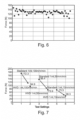
- FIG 7 This is another diagram showing test results for extrusion forces of a syringe barrel according to the invention compared to extrusion forces of a known product from the prior art.
- the various measurements are plotted along the x-axis of the diagram.
- the y-axis indicates the measured extrusion force.
- the diagram shows measurements at three different test speeds.
- a syringe body was compared according to the Figures 1 to 5
- the example shown used a "SCHOTT COC Standard” syringe barrel with a 1 ml filling volume (designation “TopPac 1 ml long”).
- a standard FM257 piston from Daetwyler was used for the plunger assembly with both syringe barrels.
- the needle assembly used with both syringe barrels was the "TSK HYPODERMIC NEEDLE” needle assembly, Ref.: HPC-30013I-320, 30 G x 1/2, with an open (non-flattened) cannula with a thickness of 30 G and a length of 13 mm.
- a highly viscous medium was used as the extruded medium.
- the highly viscous medium had a storage modulus G' of approximately 84.5 Pa and a loss factor tan ⁇ of approximately 0.48.
- the viscosity was measured using a plate-on-plate measuring system. at 25°C and an air pressure of 1013.25 hPa (e.g., rheometer manufacturer: Anton Paar MCR 302). The frequency was 1 Hz. The measurement was conducted according to ISO standard 6721-10-2015-09.
- test results show that at a test speed of 100 mm/min the extrusion force of the syringe body according to the invention was reduced from 172.3 N to 94.9 N compared to the syringe body from the prior art. Furthermore, the test results show that at a test speed of 50 mm/min the extrusion force of the syringe body according to the invention was reduced from 136.4 N to 73.9 N compared to the syringe body from the prior art. Furthermore, the test results show that at a test speed of 10 mm/min the extrusion force of the syringe body according to the invention was reduced from 73.5 N to 38.3 N compared to the syringe body from the prior art.
- the extrusion forces of the syringe body 12 according to the invention are thus significantly lower than the extrusion forces of known syringe bodies.
- the syringe body according to the invention thus requires less force from the user to dispense highly viscous media, thereby enabling improved dosing accuracy.
- the syringe bodies according to the invention allow the use of needle assemblies with thin cannulas, i.e., a thickness of 30 G or more.
- Injection device A Distance 12 syringe body B Distance 14 Piston rod arrangement C Total cone length 16 Needle arrangement I 1 smallest inner diameter 18 distal end section I 2 largest inner diameter 20 proximal end section UH Outer diameter 22 Luer-Lock connector B K Wide comb 24 flange B G Width base 26 piston rod ⁇ Angle on the thread profile 28 Pistons ⁇ further angle on the thread profile 30 Handle Y Angle of the bevel 32 Needle attachment I K Chamber inner diameter 34 Cannula V absorbable volume 36 fin L SK Total length 38 Lid O Distance 40 Outer cone s Length of the air bubble 42 opening t Piston length 44 sleeve-shaped section and Distance 46 internal thread w Length of the bevel 50, 50' Comb 54, 54' Reason 56 frontal surface 58 distal collar 60 chamfer L Longitudinal axis
Landscapes
- Health & Medical Sciences (AREA)
- Life Sciences & Earth Sciences (AREA)
- Veterinary Medicine (AREA)
- Public Health (AREA)
- General Health & Medical Sciences (AREA)
- Animal Behavior & Ethology (AREA)
- Heart & Thoracic Surgery (AREA)
- Hematology (AREA)
- Biomedical Technology (AREA)
- Anesthesiology (AREA)
- Engineering & Computer Science (AREA)
- Vascular Medicine (AREA)
- Molecular Biology (AREA)
- Dermatology (AREA)
- Chemical & Material Sciences (AREA)
- Medicinal Chemistry (AREA)
- Pharmacology & Pharmacy (AREA)
- Epidemiology (AREA)
- Infusion, Injection, And Reservoir Apparatuses (AREA)
- Cosmetics (AREA)
Claims (11)
- Dispositif d'injection (10) pour injecter un milieu hautement visqueux, comprenant une seringue pour injecter un milieu hautement visqueux, comprenant un corps de seringue (12) et un ensemble de tige de piston (14), et un ensemble d'aiguille (16) comprenant une embase d'aiguille (32) et une canule (34),dans lequel le corps de seringue (12) comprend une partie d'extrémité distale (18) et une partie d'extrémité proximale (20),dans lequel le corps de seringue (12) est cylindrique creux et forme une chambre pour recevoir le milieu hautement visqueux,dans lequel la partie d'extrémité proximale (20) comporte une ouverture à travers laquelle un ensemble de tige de piston (14) peut être inséré dans la chambre,dans lequel l'ensemble de tige de piston (14) comprend une tige de piston (26) et un piston (28) monté sur une extrémité distale de la tige de piston (26), le piston (28) étant reçu dans la chambre par l'intermédiaire de l'ouverture sur la partie d'extrémité proximale (20) du corps de seringue (12) et étant guidé de manière déplaçable dans la chambre,dans lequel un connecteur Luer-Lock (22) est formé sur la partie d'extrémité distale (18) du corps de seringue (12), lequel comprend un cône extérieur (40) avec une autre ouverture (42) pour distribuer le milieu très visqueux et une partie en forme de manchon (44) avec un filetage intérieur (46),dans lequel l'embase d'aiguille (32) destiné à établir une connexion Luer-Lock entre le corps de seringue (12) et l'ensemble d'aiguille (16) comprend une contre-pièce de connecteur Luer-Lock (36) complémentaire du connecteur Luer-Lock (22) du corps de seringue (12),et dans lequel le corps de seringue (12) a une résistance NPO minimale, mesurée selon la méthode spécifiée dans la description de la page 3 à la page 5, comprise entre 90 N et 105 N pour une connexion Luer-Lock du connecteur Luer-Lock (22) avec le connecteur Luer-Lock complémentaire (36),dans lequel le corps de seringue comprend, au niveau de la partie d'extrémité proximale (20), une surface périphérique intérieure avec un chanfrein (60) qui rétrécit la surface périphérique intérieure lorsqu'elle est vue depuis la partie d'extrémité proximale (20) en direction de la partie d'extrémité distale (18), caractérisé en ce que, le chanfrein (60), vu dans la direction d'un axe longitudinal (L) du corps de seringue (12), a une longueur (w) comprise entre 1,2 mm et 1,8 mm, de préférence entre 1,4 mm et 1,6 mm, de préférence de 1,5 mm et/ou dans lequel le chanfrein (60) forme un angle (y) d'au moins 13°, de préférence d'au moins 14°, de préférence d'au moins 15° avec l'axe longitudinal (L).
- Dispositif d'injection (10) selon la revendication 1, dans lequel le corps de seringue (12) a une résistance NPO moyenne d'au moins 110 N, de préférence d'au moins 115 N, de préférence encore d'au moins 117 N.
- Dispositif d'injection (10) selon la revendication 1 ou 2, dans lequel le filetage interne (46) présente un plus petit diamètre interne (I1) compris entre 7,05 mm et 7,15 mm, de préférence entre 7,08 mm et 7,12 mm, de préférence de 7,1 mm.
- Dispositif d'injection (10) selon l'une quelconque des revendications précédentes, dans lequel le filetage interne (46) au niveau de la crête (50) du profil de filetage a une largeur (Bk) comprise entre 0,44 mm et 0,52 mm, de préférence entre 0,46 mm et 0,50 mm, de préférence de 0,48 mm.
- Dispositif d'injection (10) selon l'une quelconque des revendications précédentes, dans lequel le filetage interne (46) à la base (54) du profilé fileté présente une largeur (BG) comprise entre 0,85 mm et 0,95 mm, de préférence entre 0,875 mm et 0,925 mm, de préférence de 0,9 mm.
- Dispositif d'injection (10) selon l'une quelconque des revendications précédentes, dans lequel une face d'extrémité distale (56) du cône extérieur (40) dépasse d'un collet distal (58) de la partie en forme de manchon (44) d'une distance (A) de 2,1 mm à 2,5 mm, de préférence de 2,2 mm à 2,4 mm, de préférence de 2,3 mm.
- Dispositif d'injection (10) selon l'une des revendications précédentes, dans lequel le corps de la seringue a une longueur totale maximale (LSK) de 80 mm et un diamètre intérieur de chambre (IK) de 5 mm au maximum, un volume (V) d'au moins 1 ml pouvant être logé dans le corps de la seringue (12).
- Dispositif d'injection (10) selon l'une des revendications précédentes, dans lequel le corps de la seringue présente, au moins dans la zone de la chambre, une épaisseur de paroi d'au moins 1,7 mm, de préférence d'au moins 1,8 mm, de préférence d'au moins 2,0 mm, de préférence encore d'au moins 2,2 mm.
- Dispositif d'injection (10) selon l'une des revendications précédentes, dans lequel le corps de la seringue est fabriqué en une matière plastique qui a de préférence un module d'élasticité compris entre 2800 MPa et 3300 MPa, en particulier entre 2900 MPa et 3200 MPa.
- Dispositif d'injection (10) selon l'une quelconque des revendications précédentes, dans lequel la canule (34) a une épaisseur d'au moins 31 G, de préférence d'au moins 32 G, de préférence d'au moins 33 G, plus préférentiellement d'au moins 34 G, encore plus préférentiellement d'au moins 35 G et/ou dans lequel l'embase d'aiguille (32) comprend un cône interne qui, le long d'un axe longitudinal de l'ensemble d'aiguille (16), a une longueur comprise entre 3 mm et 7 mm, de préférence entre 5,5 mm et 6,5 mm, de préférence de 6,1 mm
- Procédé cosmétique comprenant
Appliquer une préparation cosmétique à haute viscosité en utilisant un dispositif d'injection selon l'une quelconque des revendications 1 à 10.
Priority Applications (6)
| Application Number | Priority Date | Filing Date | Title |
|---|---|---|---|
| EP19154910.4A EP3689397B1 (fr) | 2019-01-31 | 2019-01-31 | Corps de seringue, seringue et dispositif d'injection permettant d'injecter un milieu à haute viscosité |
| US16/750,525 US11918797B2 (en) | 2019-01-31 | 2020-01-23 | Syringe body, syringe and injection device for injecting a highly viscous medium |
| JP2020013726A JP7609560B2 (ja) | 2019-01-31 | 2020-01-30 | 高粘度媒体を注射するためのシリンジ、注射器および注射装置 |
| CN202010079010.4A CN111494755A (zh) | 2019-01-31 | 2020-02-03 | 一种用于注射高粘性介质的注射器本体、注射器和注射装置 |
| CN202020150884.XU CN212439598U (zh) | 2019-01-31 | 2020-02-03 | 一种用于注射高粘性介质的注射器本体、注射器和注射装置 |
| JP2024224129A JP7717946B2 (ja) | 2019-01-31 | 2024-12-19 | 高粘度媒体を注射するためのシリンジ、注射器および注射装置 |
Applications Claiming Priority (1)
| Application Number | Priority Date | Filing Date | Title |
|---|---|---|---|
| EP19154910.4A EP3689397B1 (fr) | 2019-01-31 | 2019-01-31 | Corps de seringue, seringue et dispositif d'injection permettant d'injecter un milieu à haute viscosité |
Publications (2)
| Publication Number | Publication Date |
|---|---|
| EP3689397A1 EP3689397A1 (fr) | 2020-08-05 |
| EP3689397B1 true EP3689397B1 (fr) | 2025-04-23 |
Family
ID=65276079
Family Applications (1)
| Application Number | Title | Priority Date | Filing Date |
|---|---|---|---|
| EP19154910.4A Active EP3689397B1 (fr) | 2019-01-31 | 2019-01-31 | Corps de seringue, seringue et dispositif d'injection permettant d'injecter un milieu à haute viscosité |
Country Status (4)
| Country | Link |
|---|---|
| US (1) | US11918797B2 (fr) |
| EP (1) | EP3689397B1 (fr) |
| JP (2) | JP7609560B2 (fr) |
| CN (2) | CN111494755A (fr) |
Families Citing this family (5)
| Publication number | Priority date | Publication date | Assignee | Title |
|---|---|---|---|---|
| EP3689397B1 (fr) * | 2019-01-31 | 2025-04-23 | SCHOTT Pharma Schweiz AG | Corps de seringue, seringue et dispositif d'injection permettant d'injecter un milieu à haute viscosité |
| WO2022207655A1 (fr) * | 2021-03-30 | 2022-10-06 | Schott Schweiz Ag | Système de stockage à basse température d'une composition pharmaceutique, composition liquide, procédé et utilisations |
| CA3237624A1 (fr) * | 2023-07-28 | 2025-04-24 | Genentech, Inc. | Nouvelles utilisations d'omalizumab |
| CN117942456B (zh) * | 2024-03-27 | 2024-07-12 | 山东永聚医药科技股份有限公司 | 缓释型非牛顿流体制剂用预灌封注射器及其制备工艺 |
| EP4692753A1 (fr) * | 2024-08-06 | 2026-02-11 | Diagenode S.A. | Appareil et seringue pour fragmenter un matériau d'échantillon d'acide nucléique |
Citations (2)
| Publication number | Priority date | Publication date | Assignee | Title |
|---|---|---|---|---|
| US5554133A (en) * | 1994-01-18 | 1996-09-10 | Allergan, Inc. | Syringe flange adapter and method |
| US20160184528A1 (en) * | 2013-09-06 | 2016-06-30 | Terumo Kabushiki Kaisha | Syringe barrel and mold for injection molding |
Family Cites Families (13)
| Publication number | Priority date | Publication date | Assignee | Title |
|---|---|---|---|---|
| US3306291A (en) * | 1964-04-14 | 1967-02-28 | Burron Medical Prod Inc | Disposable sterile syringes, needle containers and the like having prestressed frangible portions therein |
| DE10223421A1 (de) * | 2002-05-25 | 2003-12-11 | Schott Glas | Spritze, insbesondere Einmalspritze, sowie Verfahren zur Herstellung einer derartigen Spritze |
| JP4522071B2 (ja) | 2002-10-24 | 2010-08-11 | テルモ株式会社 | シリンジ |
| US20060178638A1 (en) * | 2004-12-03 | 2006-08-10 | Reynolds David L | Device and method for pharmaceutical mixing and delivery |
| EP1726285A1 (fr) * | 2005-05-24 | 2006-11-29 | Vifor (International) Ag | Réceptacle distributeur pour médicaments et dispositif d'administration associé |
| US20090143746A1 (en) | 2007-11-30 | 2009-06-04 | Mudd Christopher S | Luer connectors, components thereof and fluent material delivery devices utilizing the same |
| EP3187219B2 (fr) * | 2008-12-02 | 2026-03-04 | Allergan, Inc. | Dispositif d'injection |
| PT2574357E (pt) * | 2011-09-28 | 2014-02-05 | Q Med Ab | Injetor eletrónico |
| DE202013000688U1 (de) * | 2012-07-03 | 2013-03-05 | Novartis Ag | Glas-Spritze |
| US11911341B2 (en) * | 2016-02-16 | 2024-02-27 | Mitsubishi Gas Chemical Company, Inc. | Multilayer vessel, and application thereof |
| EP3689397B1 (fr) * | 2019-01-31 | 2025-04-23 | SCHOTT Pharma Schweiz AG | Corps de seringue, seringue et dispositif d'injection permettant d'injecter un milieu à haute viscosité |
| EP3777928B1 (fr) * | 2019-08-12 | 2021-10-06 | Schott AG | Cylindre de seringue en verre ayant une force de rupture de cône accrue |
| EP3777935B1 (fr) * | 2019-08-15 | 2026-03-11 | SCHOTT Pharma Schweiz AG | Dispositif de retenue d'aiguille pour retenir une aiguille de l'ensemble aiguille lorsqu'il est fixé à une seringue |
-
2019
- 2019-01-31 EP EP19154910.4A patent/EP3689397B1/fr active Active
-
2020
- 2020-01-23 US US16/750,525 patent/US11918797B2/en active Active
- 2020-01-30 JP JP2020013726A patent/JP7609560B2/ja active Active
- 2020-02-03 CN CN202010079010.4A patent/CN111494755A/zh active Pending
- 2020-02-03 CN CN202020150884.XU patent/CN212439598U/zh active Active
-
2024
- 2024-12-19 JP JP2024224129A patent/JP7717946B2/ja active Active
Patent Citations (2)
| Publication number | Priority date | Publication date | Assignee | Title |
|---|---|---|---|---|
| US5554133A (en) * | 1994-01-18 | 1996-09-10 | Allergan, Inc. | Syringe flange adapter and method |
| US20160184528A1 (en) * | 2013-09-06 | 2016-06-30 | Terumo Kabushiki Kaisha | Syringe barrel and mold for injection molding |
Also Published As
| Publication number | Publication date |
|---|---|
| US11918797B2 (en) | 2024-03-05 |
| CN212439598U (zh) | 2021-02-02 |
| JP7609560B2 (ja) | 2025-01-07 |
| EP3689397A1 (fr) | 2020-08-05 |
| JP2020124496A (ja) | 2020-08-20 |
| CN111494755A (zh) | 2020-08-07 |
| JP7717946B2 (ja) | 2025-08-04 |
| US20200246555A1 (en) | 2020-08-06 |
| JP2025032379A (ja) | 2025-03-11 |
Similar Documents
| Publication | Publication Date | Title |
|---|---|---|
| EP3689397B1 (fr) | Corps de seringue, seringue et dispositif d'injection permettant d'injecter un milieu à haute viscosité | |
| DE69533027T2 (de) | Spritze mit flanschadapter | |
| DE3621374C2 (fr) | ||
| DE60129431T2 (de) | Medizinische vorrichtung | |
| DE69938389T2 (de) | Spritzvorrichtung | |
| DE60021633T2 (de) | Hilfswerkzeug zum Auspressen eines chemischen Wirkstoffes, Kneter zum Vorbereiten und Auspressen eines chemischen Wirkstoffes, und Verfahren zur Verwendung derselben | |
| DE69724349T2 (de) | Kolben für Spritze | |
| DE60220384T2 (de) | Spritze- und nadelschutzhülsevorrichtung und verfahren zu deren sterilisation | |
| DE69702973T2 (de) | Verfahren zum füllen einer medizinkapsel und dabei erzeugter gegenstand | |
| DE69922027T2 (de) | Spritzen zur verabreichung von zähflüssigen oder halbfesten stoffen | |
| DE69633297T2 (de) | Kupplungssystem für eine sicherheitskanüle | |
| EP1658107B1 (fr) | Dispositif d'injection d'un produit injectable | |
| DE9090047U1 (de) | Verriegelbare Spritze | |
| EP0806972A1 (fr) | Procede et dispositif de manipulation sous pression regulee d'un fluide, en particulier pour applications medicales | |
| DE4428467A1 (de) | Spritze mit Kolbendruckdämpfung und Verfahren zur langsamen und gleichmäßigen Injektion einer Flüssigkeit mittels dieser Spritze | |
| DE2259825A1 (de) | Injektionsspritze | |
| DE1491695A1 (de) | Ampulle fuer nadelfreie Injektionseinrichtungen | |
| EP2237820A2 (fr) | Système d'injection d'un fluide à travers, ou dans la peau humaine | |
| DE3808688A1 (de) | Kanuelenschutzeinrichtung | |
| EP1180377A1 (fr) | Seringue avec piston | |
| EP3530304A1 (fr) | Canule pour ponction et injection intravitréennes | |
| EP3976139A1 (fr) | Corps médical creux, corps médical creux doté d'un capuchon de fermeture, procédé de fabrication d'un corps médical creux, et kit | |
| EP4063007A1 (fr) | Procédé et dispositif de mélange du ciment osseux à dépressurisation | |
| EP4138962A1 (fr) | Butée de piston pour seringue médicale et seringue médicale à butée de piston | |
| DE4134655C2 (de) | Medizinisches Einstichinstrument |
Legal Events
| Date | Code | Title | Description |
|---|---|---|---|
| STAA | Information on the status of an ep patent application or granted ep patent |
Free format text: STATUS: EXAMINATION IS IN PROGRESS |
|
| PUAI | Public reference made under article 153(3) epc to a published international application that has entered the european phase |
Free format text: ORIGINAL CODE: 0009012 |
|
| 17P | Request for examination filed |
Effective date: 20190131 |
|
| AK | Designated contracting states |
Kind code of ref document: A1 Designated state(s): AL AT BE BG CH CY CZ DE DK EE ES FI FR GB GR HR HU IE IS IT LI LT LU LV MC MK MT NL NO PL PT RO RS SE SI SK SM TR |
|
| AX | Request for extension of the european patent |
Extension state: BA ME |
|
| RAP3 | Party data changed (applicant data changed or rights of an application transferred) |
Owner name: SCHOTT PHARMA SCHWEIZ AG |
|
| P01 | Opt-out of the competence of the unified patent court (upc) registered |
Effective date: 20230512 |
|
| GRAP | Despatch of communication of intention to grant a patent |
Free format text: ORIGINAL CODE: EPIDOSNIGR1 |
|
| STAA | Information on the status of an ep patent application or granted ep patent |
Free format text: STATUS: GRANT OF PATENT IS INTENDED |
|
| INTG | Intention to grant announced |
Effective date: 20241118 |
|
| GRAS | Grant fee paid |
Free format text: ORIGINAL CODE: EPIDOSNIGR3 |
|
| GRAA | (expected) grant |
Free format text: ORIGINAL CODE: 0009210 |
|
| STAA | Information on the status of an ep patent application or granted ep patent |
Free format text: STATUS: THE PATENT HAS BEEN GRANTED |
|
| AK | Designated contracting states |
Kind code of ref document: B1 Designated state(s): AL AT BE BG CH CY CZ DE DK EE ES FI FR GB GR HR HU IE IS IT LI LT LU LV MC MK MT NL NO PL PT RO RS SE SI SK SM TR |
|
| REG | Reference to a national code |
Ref country code: GB Ref legal event code: FG4D Free format text: NOT ENGLISH |
|
| REG | Reference to a national code |
Ref country code: CH Ref legal event code: EP |
|
| REG | Reference to a national code |
Ref country code: DE Ref legal event code: R096 Ref document number: 502019013234 Country of ref document: DE |
|
| REG | Reference to a national code |
Ref country code: IE Ref legal event code: FG4D Free format text: LANGUAGE OF EP DOCUMENT: GERMAN |
|
| REG | Reference to a national code |
Ref country code: NL Ref legal event code: MP Effective date: 20250423 |
|
| PG25 | Lapsed in a contracting state [announced via postgrant information from national office to epo] |
Ref country code: NL Free format text: LAPSE BECAUSE OF FAILURE TO SUBMIT A TRANSLATION OF THE DESCRIPTION OR TO PAY THE FEE WITHIN THE PRESCRIBED TIME-LIMIT Effective date: 20250423 |
|
| PG25 | Lapsed in a contracting state [announced via postgrant information from national office to epo] |
Ref country code: FI Free format text: LAPSE BECAUSE OF FAILURE TO SUBMIT A TRANSLATION OF THE DESCRIPTION OR TO PAY THE FEE WITHIN THE PRESCRIBED TIME-LIMIT Effective date: 20250423 Ref country code: PT Free format text: LAPSE BECAUSE OF FAILURE TO SUBMIT A TRANSLATION OF THE DESCRIPTION OR TO PAY THE FEE WITHIN THE PRESCRIBED TIME-LIMIT Effective date: 20250825 Ref country code: ES Free format text: LAPSE BECAUSE OF FAILURE TO SUBMIT A TRANSLATION OF THE DESCRIPTION OR TO PAY THE FEE WITHIN THE PRESCRIBED TIME-LIMIT Effective date: 20250423 |
|
| REG | Reference to a national code |
Ref country code: LT Ref legal event code: MG9D |
|
| PG25 | Lapsed in a contracting state [announced via postgrant information from national office to epo] |
Ref country code: GR Free format text: LAPSE BECAUSE OF FAILURE TO SUBMIT A TRANSLATION OF THE DESCRIPTION OR TO PAY THE FEE WITHIN THE PRESCRIBED TIME-LIMIT Effective date: 20250724 Ref country code: NO Free format text: LAPSE BECAUSE OF FAILURE TO SUBMIT A TRANSLATION OF THE DESCRIPTION OR TO PAY THE FEE WITHIN THE PRESCRIBED TIME-LIMIT Effective date: 20250723 |
|
| PG25 | Lapsed in a contracting state [announced via postgrant information from national office to epo] |
Ref country code: PL Free format text: LAPSE BECAUSE OF FAILURE TO SUBMIT A TRANSLATION OF THE DESCRIPTION OR TO PAY THE FEE WITHIN THE PRESCRIBED TIME-LIMIT Effective date: 20250423 |
|
| PG25 | Lapsed in a contracting state [announced via postgrant information from national office to epo] |
Ref country code: BG Free format text: LAPSE BECAUSE OF FAILURE TO SUBMIT A TRANSLATION OF THE DESCRIPTION OR TO PAY THE FEE WITHIN THE PRESCRIBED TIME-LIMIT Effective date: 20250423 |
|
| PG25 | Lapsed in a contracting state [announced via postgrant information from national office to epo] |
Ref country code: HR Free format text: LAPSE BECAUSE OF FAILURE TO SUBMIT A TRANSLATION OF THE DESCRIPTION OR TO PAY THE FEE WITHIN THE PRESCRIBED TIME-LIMIT Effective date: 20250423 |
|
| PG25 | Lapsed in a contracting state [announced via postgrant information from national office to epo] |
Ref country code: RS Free format text: LAPSE BECAUSE OF FAILURE TO SUBMIT A TRANSLATION OF THE DESCRIPTION OR TO PAY THE FEE WITHIN THE PRESCRIBED TIME-LIMIT Effective date: 20250723 |
|
| PG25 | Lapsed in a contracting state [announced via postgrant information from national office to epo] |
Ref country code: IS Free format text: LAPSE BECAUSE OF FAILURE TO SUBMIT A TRANSLATION OF THE DESCRIPTION OR TO PAY THE FEE WITHIN THE PRESCRIBED TIME-LIMIT Effective date: 20250823 |
|
| PG25 | Lapsed in a contracting state [announced via postgrant information from national office to epo] |
Ref country code: LV Free format text: LAPSE BECAUSE OF FAILURE TO SUBMIT A TRANSLATION OF THE DESCRIPTION OR TO PAY THE FEE WITHIN THE PRESCRIBED TIME-LIMIT Effective date: 20250423 |
|
| PG25 | Lapsed in a contracting state [announced via postgrant information from national office to epo] |
Ref country code: DK Free format text: LAPSE BECAUSE OF FAILURE TO SUBMIT A TRANSLATION OF THE DESCRIPTION OR TO PAY THE FEE WITHIN THE PRESCRIBED TIME-LIMIT Effective date: 20250423 Ref country code: SM Free format text: LAPSE BECAUSE OF FAILURE TO SUBMIT A TRANSLATION OF THE DESCRIPTION OR TO PAY THE FEE WITHIN THE PRESCRIBED TIME-LIMIT Effective date: 20250423 |
|
| PG25 | Lapsed in a contracting state [announced via postgrant information from national office to epo] |
Ref country code: CZ Free format text: LAPSE BECAUSE OF FAILURE TO SUBMIT A TRANSLATION OF THE DESCRIPTION OR TO PAY THE FEE WITHIN THE PRESCRIBED TIME-LIMIT Effective date: 20250423 |
|
| PG25 | Lapsed in a contracting state [announced via postgrant information from national office to epo] |
Ref country code: EE Free format text: LAPSE BECAUSE OF FAILURE TO SUBMIT A TRANSLATION OF THE DESCRIPTION OR TO PAY THE FEE WITHIN THE PRESCRIBED TIME-LIMIT Effective date: 20250423 |
|
| REG | Reference to a national code |
Ref country code: DE Ref legal event code: R097 Ref document number: 502019013234 Country of ref document: DE |
|
| PG25 | Lapsed in a contracting state [announced via postgrant information from national office to epo] |
Ref country code: SK Free format text: LAPSE BECAUSE OF FAILURE TO SUBMIT A TRANSLATION OF THE DESCRIPTION OR TO PAY THE FEE WITHIN THE PRESCRIBED TIME-LIMIT Effective date: 20250423 Ref country code: RO Free format text: LAPSE BECAUSE OF FAILURE TO SUBMIT A TRANSLATION OF THE DESCRIPTION OR TO PAY THE FEE WITHIN THE PRESCRIBED TIME-LIMIT Effective date: 20250423 |
|
| REG | Reference to a national code |
Ref country code: CH Ref legal event code: U11 Free format text: ST27 STATUS EVENT CODE: U-0-0-U10-U11 (AS PROVIDED BY THE NATIONAL OFFICE) Effective date: 20260201 |
|
| PLBE | No opposition filed within time limit |
Free format text: ORIGINAL CODE: 0009261 |
|
| STAA | Information on the status of an ep patent application or granted ep patent |
Free format text: STATUS: NO OPPOSITION FILED WITHIN TIME LIMIT |
|
| REG | Reference to a national code |
Ref country code: CH Ref legal event code: L10 Free format text: ST27 STATUS EVENT CODE: U-0-0-L10-L00 (AS PROVIDED BY THE NATIONAL OFFICE) Effective date: 20260304 |