EP3689186B1 - Rolle für apparate, möbel, mit einem ein kopfteil und ein fussteil aufweisendes tragteil - Google Patents
Rolle für apparate, möbel, mit einem ein kopfteil und ein fussteil aufweisendes tragteil Download PDFInfo
- Publication number
- EP3689186B1 EP3689186B1 EP20152223.2A EP20152223A EP3689186B1 EP 3689186 B1 EP3689186 B1 EP 3689186B1 EP 20152223 A EP20152223 A EP 20152223A EP 3689186 B1 EP3689186 B1 EP 3689186B1
- Authority
- EP
- European Patent Office
- Prior art keywords
- support part
- cover
- roller
- wheel
- support
- Prior art date
- Legal status (The legal status is an assumption and is not a legal conclusion. Google has not performed a legal analysis and makes no representation as to the accuracy of the status listed.)
- Active
Links
Images


Classifications
-
- B—PERFORMING OPERATIONS; TRANSPORTING
- B60—VEHICLES IN GENERAL
- B60B—VEHICLE WHEELS; CASTORS; AXLES FOR WHEELS OR CASTORS; INCREASING WHEEL ADHESION
- B60B33/00—Castors in general ; Anti-clogging castors
-
- A—HUMAN NECESSITIES
- A47—FURNITURE; DOMESTIC ARTICLES OR APPLIANCES; COFFEE MILLS; SPICE MILLS; SUCTION CLEANERS IN GENERAL
- A47B—TABLES; DESKS; OFFICE FURNITURE; CABINETS; DRAWERS; GENERAL DETAILS OF FURNITURE
- A47B91/00—Feet for furniture in general
-
- B—PERFORMING OPERATIONS; TRANSPORTING
- B60—VEHICLES IN GENERAL
- B60B—VEHICLE WHEELS; CASTORS; AXLES FOR WHEELS OR CASTORS; INCREASING WHEEL ADHESION
- B60B33/00—Castors in general ; Anti-clogging castors
- B60B33/0002—Castors in general ; Anti-clogging castors assembling to the object, e.g. furniture
- B60B33/0015—Castors in general ; Anti-clogging castors assembling to the object, e.g. furniture characterised by adaptations made to castor
-
- B—PERFORMING OPERATIONS; TRANSPORTING
- B60—VEHICLES IN GENERAL
- B60B—VEHICLE WHEELS; CASTORS; AXLES FOR WHEELS OR CASTORS; INCREASING WHEEL ADHESION
- B60B33/00—Castors in general ; Anti-clogging castors
- B60B33/0002—Castors in general ; Anti-clogging castors assembling to the object, e.g. furniture
- B60B33/0015—Castors in general ; Anti-clogging castors assembling to the object, e.g. furniture characterised by adaptations made to castor
- B60B33/0021—Castors in general ; Anti-clogging castors assembling to the object, e.g. furniture characterised by adaptations made to castor in the form of a mounting pin
-
- B—PERFORMING OPERATIONS; TRANSPORTING
- B60—VEHICLES IN GENERAL
- B60B—VEHICLE WHEELS; CASTORS; AXLES FOR WHEELS OR CASTORS; INCREASING WHEEL ADHESION
- B60B7/00—Wheel cover discs, rings, or the like, for ornamenting, protecting, venting, or obscuring, wholly or in part, the wheel body, rim, hub, or tyre sidewall, e.g. wheel cover discs, wheel cover discs with cooling fins
- B60B7/06—Fastening arrangements therefor
- B60B7/08—Fastening arrangements therefor having gripping elements consisting of formations integral with the cover
-
- B—PERFORMING OPERATIONS; TRANSPORTING
- B60—VEHICLES IN GENERAL
- B60B—VEHICLE WHEELS; CASTORS; AXLES FOR WHEELS OR CASTORS; INCREASING WHEEL ADHESION
- B60B2200/00—Type of product being used or applied
- B60B2200/20—Furniture or medical appliances
-
- B—PERFORMING OPERATIONS; TRANSPORTING
- B60—VEHICLES IN GENERAL
- B60B—VEHICLE WHEELS; CASTORS; AXLES FOR WHEELS OR CASTORS; INCREASING WHEEL ADHESION
- B60B2360/00—Materials; Physical forms thereof
- B60B2360/30—Synthetic materials
- B60B2360/32—Plastic compositions
- B60B2360/322—Comprising polypropylene
-
- B—PERFORMING OPERATIONS; TRANSPORTING
- B60—VEHICLES IN GENERAL
- B60B—VEHICLE WHEELS; CASTORS; AXLES FOR WHEELS OR CASTORS; INCREASING WHEEL ADHESION
- B60B2900/00—Purpose of invention
- B60B2900/10—Reduction of
- B60B2900/116—Product variety, e.g. by standardisation or use of adapters
-
- B—PERFORMING OPERATIONS; TRANSPORTING
- B60—VEHICLES IN GENERAL
- B60B—VEHICLE WHEELS; CASTORS; AXLES FOR WHEELS OR CASTORS; INCREASING WHEEL ADHESION
- B60B2900/00—Purpose of invention
- B60B2900/30—Increase in
- B60B2900/351—Increase in versatility, e.g. usable for different purposes or different arrangements
-
- B—PERFORMING OPERATIONS; TRANSPORTING
- B60—VEHICLES IN GENERAL
- B60B—VEHICLE WHEELS; CASTORS; AXLES FOR WHEELS OR CASTORS; INCREASING WHEEL ADHESION
- B60B2900/00—Purpose of invention
- B60B2900/50—Improvement of
- B60B2900/572—Visual appearance
-
- B—PERFORMING OPERATIONS; TRANSPORTING
- B60—VEHICLES IN GENERAL
- B60B—VEHICLE WHEELS; CASTORS; AXLES FOR WHEELS OR CASTORS; INCREASING WHEEL ADHESION
- B60B33/00—Castors in general ; Anti-clogging castors
- B60B33/0036—Castors in general ; Anti-clogging castors characterised by type of wheels
- B60B33/0039—Single wheels
-
- B—PERFORMING OPERATIONS; TRANSPORTING
- B60—VEHICLES IN GENERAL
- B60B—VEHICLE WHEELS; CASTORS; AXLES FOR WHEELS OR CASTORS; INCREASING WHEEL ADHESION
- B60B33/00—Castors in general ; Anti-clogging castors
- B60B33/0047—Castors in general ; Anti-clogging castors characterised by details of the rolling axle
- B60B33/0049—Castors in general ; Anti-clogging castors characterised by details of the rolling axle the rolling axle being horizontal
-
- B—PERFORMING OPERATIONS; TRANSPORTING
- B60—VEHICLES IN GENERAL
- B60B—VEHICLE WHEELS; CASTORS; AXLES FOR WHEELS OR CASTORS; INCREASING WHEEL ADHESION
- B60B33/00—Castors in general ; Anti-clogging castors
- B60B33/0047—Castors in general ; Anti-clogging castors characterised by details of the rolling axle
- B60B33/0057—Castors in general ; Anti-clogging castors characterised by details of the rolling axle the rolling axle being offset from swivel axis
-
- B—PERFORMING OPERATIONS; TRANSPORTING
- B60—VEHICLES IN GENERAL
- B60B—VEHICLE WHEELS; CASTORS; AXLES FOR WHEELS OR CASTORS; INCREASING WHEEL ADHESION
- B60B33/00—Castors in general ; Anti-clogging castors
- B60B33/006—Castors in general ; Anti-clogging castors characterised by details of the swivel mechanism
- B60B33/0065—Castors in general ; Anti-clogging castors characterised by details of the swivel mechanism characterised by details of the swivel axis
- B60B33/0068—Castors in general ; Anti-clogging castors characterised by details of the swivel mechanism characterised by details of the swivel axis the swivel axis being vertical
-
- B—PERFORMING OPERATIONS; TRANSPORTING
- B60—VEHICLES IN GENERAL
- B60B—VEHICLE WHEELS; CASTORS; AXLES FOR WHEELS OR CASTORS; INCREASING WHEEL ADHESION
- B60B33/00—Castors in general ; Anti-clogging castors
- B60B33/006—Castors in general ; Anti-clogging castors characterised by details of the swivel mechanism
- B60B33/0065—Castors in general ; Anti-clogging castors characterised by details of the swivel mechanism characterised by details of the swivel axis
- B60B33/0073—Castors in general ; Anti-clogging castors characterised by details of the swivel mechanism characterised by details of the swivel axis the swivel axis being symmetrical to wheel or wheels
-
- B—PERFORMING OPERATIONS; TRANSPORTING
- B60—VEHICLES IN GENERAL
- B60B—VEHICLE WHEELS; CASTORS; AXLES FOR WHEELS OR CASTORS; INCREASING WHEEL ADHESION
- B60B7/00—Wheel cover discs, rings, or the like, for ornamenting, protecting, venting, or obscuring, wholly or in part, the wheel body, rim, hub, or tyre sidewall, e.g. wheel cover discs, wheel cover discs with cooling fins
-
- B—PERFORMING OPERATIONS; TRANSPORTING
- B60—VEHICLES IN GENERAL
- B60B—VEHICLE WHEELS; CASTORS; AXLES FOR WHEELS OR CASTORS; INCREASING WHEEL ADHESION
- B60B7/00—Wheel cover discs, rings, or the like, for ornamenting, protecting, venting, or obscuring, wholly or in part, the wheel body, rim, hub, or tyre sidewall, e.g. wheel cover discs, wheel cover discs with cooling fins
- B60B7/0026—Wheel cover discs, rings, or the like, for ornamenting, protecting, venting, or obscuring, wholly or in part, the wheel body, rim, hub, or tyre sidewall, e.g. wheel cover discs, wheel cover discs with cooling fins characterised by the surface
- B60B7/0033—Wheel cover discs, rings, or the like, for ornamenting, protecting, venting, or obscuring, wholly or in part, the wheel body, rim, hub, or tyre sidewall, e.g. wheel cover discs, wheel cover discs with cooling fins characterised by the surface the dominant aspect being the surface appearance
Definitions
- the invention relates to a castor for apparatus and furniture, with a support part having a head part and a foot part, the head part of which accommodates a fastening bolt and the foot part of which supports a wheel axle, on which at least one wheel is arranged and that adjacent to the support part running largely around a one-piece, one continuous design surface forming support part cover made of plastic is arranged interchangeably.
- Such a role is from the D1 GB 2561032A known with a slipped over separate protective cover, which surrounds almost the entire role, including the wheel, at a distance from the supporting part and which is obviously intended to prevent the penetration of microbes, dirt and other harmful particles into the role. Also, this roller seems to have a certain protective function, especially for the human feet when the object provided with rollers is moved.
- the object of the invention is therefore to create a new castor for apparatus and furniture with which a large number of castors designed according to the individual wishes of the customer can be produced in a cost-effective manner.
- Castor (10) for apparatus and furniture with a support part (11) having a head part (12) and a foot part (13), the head part (12) of which receives a fastening bolt (17) and the foot part (13) of which receives a wheel axle (14) on which at least one wheel (15) is arranged and that a one-piece supporting part cover (19) made of plastic and forming a continuous design surface is arranged interchangeably on the supporting part (11), characterized in that the inner surfaces of the supporting part cover (19) in The area of the wheel cover areas (20) and the supporting part cover areas (21) each have two locking elements (23) which are locked in the mounted state in the supporting part (11) and that the inner surfaces of the wheel cover areas (20) each have two support areas (24) are provided, which engage in a form-fitting manner after the fastening of the supporting part cover in the supporting part.
- the role according to the invention has the significant advantage that it can be used to customize one and the same role in a variety of ways according to customer requirements by attaching different supporting part covers.
- roller itself can be produced in large quantities and thus inexpensively and that this roller that is in stock can then be offered and delivered in a desired design at short notice according to customer requirements, since a large number of different supporting part covers are also available Are available.
- the supporting part cover is formed from polypropylene.
- this material is not only inexpensive, but it does not absorb moisture and pre-drying is not necessary.
- the supporting part cover can be snapped onto the supporting part by means of a plurality of locking means.
- This type of attachment is not only easy to manufacture and assemble, but also allows for a continuous design surface with no visible attachment points.
- a unicycle roller is identified as a whole with the reference numeral 10.
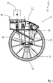
- the 1 shows the unicycle roller 10 in side view.
- a supporting part (supporting housing) 11 can be seen in this illustration, which is formed from a head part 12 and a foot part 13 .
- a wheel 15 is rotatably arranged on the foot part 13 by means of a wheel axle 14 .
- a rotary bearing is arranged on the head part 12 in a manner not shown under a bearing cover cap 16, with a fastening bolt 17 protruding upwards out of the bearing cover cap 16 for arrangement, for example, on a hospital bed.
- FIG figure 4 shows the unicycle roller 10 with the support part cover 19 arranged thereon.
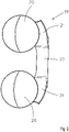
- the supporting part cover 19 is a plastic part, preferably made of polypropylene, which has two wheel cover areas 20, two support part cover areas 21 and a flexible central part 22.
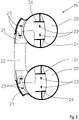
- the inner surfaces of the support part cover 19 in the area of the wheel cover areas 20 and the support part cover areas 21 each have two locking elements 23 which are locked in the manner described below in the mounted state in the support part 11 .
- the inner surfaces of the wheel cover areas 20 are each provided with two support areas 24 which engage in a form-fitting manner after the attachment of the support part cover 19 in the support part 11 .
- the support areas 24 serve to absorb any lateral forces that may occur on the support part 11 so that the locking elements 23 remain unloaded.
- FIG 5 is an enlarged partial sectional view taken along section line VV in figure 4 shown.
- the supporting part cover 19 engages behind a locking projection 25 formed on the supporting part 11 with the aid of a locking means 23 .
- the supporting part cover 19 is reliably fastened to the unicycle roller 10 by the two latching means 23 arranged on each wheel cover area 20 and on each supporting part covering area 21 .
Landscapes
- Engineering & Computer Science (AREA)
- Mechanical Engineering (AREA)
- Legs For Furniture In General (AREA)
Description
- Die Erfindung betrifft eine Rolle für Apparate und Möbel, mit einem ein Kopfteil und ein Fußteil aufweisendes Tragteil, dessen Kopfteil einen Befestigungsbolzen aufnimmt und dessen Fußteil eine Radachse lagert, an der mindestens ein Rad angeordnet ist und dass anliegend am Tragteil weitgehend umlaufend eine einstückige, eine durchgehende Designfläche ausbildende Tragteilabdeckung aus Kunststoff austauschbar angeordnet ist.
- Eine derartige Rolle ist aus der D1
GB 2561032 A - Des Weiteren ist aus der D2
US 2,483,241 A ebenfalls eine derartige Rolle offenbart, bei der eine offensichtlich flexible biegsame Schutzabdeckung von oben über den Bolzen und die Rolle gestülpt wird und diese Schutzhülle weitgehend auch das Rad abdeckt. Auch diese hat zum Ziel, während des Betriebs die Rolle und Gegenstände mit denen die Rolle kollidiert, zu schützen. - Letztlich offenbart auch die D3
US 6 125 504 A einen Bürostuhl-Rollenschutz, welcher mit großem Abstand über eine oder mehrere Stuhlrollen gestülpt wird und welcher - den Schutz der Schuhe der sitzenden Person oder der umgebenden Möbel dient. Auch diese Schutzhülle hat einen großen Abstand zu den eigentlichen Rollen. - Zwar haben diese Rollen nach dem Stand der Technik den Vorteil, dass sie auch mit Schutzhüllen, die unterschiedliches Design aufweisen, umhüllt werden können, jedoch ist eine derartige Lösung sehr aufwändig und designtechnisch nachteilig.
- Zugleich steigt die Nachfrage der Kunden nach individueller Ausgestaltung der Rollen bei gleichzeitig sinkenden Stückzahlen der einzelnen Rollen und die Kosten für die Herstellung der Vielzahl von Varianten steigt.
- Die Aufgabe der Erfindung besteht deshalb darin, eine neue Rolle für Apparate und Möbel zu schaffen, mit der auf kostengünstige Weise eine Vielzahl von nach den individuellen Wünschen der Kunden ausgestalteten Rollen herstellbar ist.
- Die Lösung der Aufgabe ergibt sich aus den Merkmalen des Anspruches 1:
Rolle (10) für Apparate und Möbel, mit einem ein Kopfteil (12) und ein Fußteil (13) aufweisendes Tragteil (11), dessen Kopfteil (12) einen Befestigungsbolzen (17) aufnimmt und dessen Fußteil (13) eine Radachse (14) lagert, an der mindestens ein Rad (15) angeordnet ist und dass am Tragteil (11) weitgehend umlaufend eine einstückige, eine durchgehende Designfläche ausbildende Tragteilabdeckung (19) aus Kunststoff austauschbar angeordnet ist, dadurch gekennzeichnet, dass die Innenflächen der Tragteilabdeckung (19) im Bereich der Radabdeckungsbereiche (20) und der Tragteilabdeckungsbereiche (21) je zwei Rastelemente (23) aufweisen, die im montierten Zustand im Tragteil (11) verrastet werden und dass die Innenflächen der Radabdeckungsbereiche (20) jeweils mit zwei Stützbereichen (24) versehen sind, die formschlüssig nach der Befestigung der Tragteilabdeckung ins Tragteil eingreifen. - Die erfindungsgemäße Rolle hat den wesentlichen Vorteil, dass mit ihr auf sehr preiswerte Weise ein- und dieselbe Rolle durch Anbringung unterschiedlicher Tragteilabdeckungen vielfältig nach Kundenwünschen individualisiert werden kann.
- In diesem Zusammenhang ist es darüber hinaus von Vorteil, dass die Rolle an sich in großen Stückzahlen und damit kostengünstig herstellbar ist und diese auf Lager liegende Rolle dann kurzfristig nach Kundenwunsch in einem gewünschten Design angeboten und geliefert werden kann, da eine Vielzahl von unterschiedlichen Tragteilabdeckungen ebenfalls verfügbar sind.
- Bei einer vorteilhaften Ausführungsform der Erfindung wird die Tragteilabdeckung aus Polypropylen gebildet. Vorteilhafterweise ist dieses Material nicht nur preiswert, sondern es nimmt keine Feuchtigkeit auf und eine Vortrocknung ist nicht notwendig.
- Auf bevorzugte Weise ist die Tragteilabdeckung mittels einer Mehrzahl von Rastmitteln auf das Tragteil aufrastbar. Diese Art der Befestigung ist nicht nur einfach herzustellen und zu montieren, sondern ermöglicht auch eine durchgehende Designfläche ohne sichtbare Befestigungsstellen.
- Weitere Vorteile der Erfindung ergeben sich aus der nachfolgenden Beschreibung eines Ausführungsbeispiels. Es zeigen:
- Figur 1:
- Seitenansicht einer Einradrolle ohne Tragteilabdeckung,
- Figur 2:
- Draufsicht auf eine Tragteilabdeckung,
- Figur 3:
- Innenansicht einer Tragteilabdeckung gemäß
Fig. 2 , - Figur 4:
- Darstellung der Einradrolle gemäß
Fig. 1 mit daran angeordneter Tragteilabdeckung, - Figur 5:
- vergrößerte Teilschnittdarstellung einer Rastmittelbefestigung gemäß Schnittlinien V-V in
Fig. 4 , - Figur 6:
- Stirnansicht der Einradrolle gemäß Ansichtspfeil VI in
Fig. 4 und - Figur 7:
- Stirnansicht der Einradrolle gemäß Ansichtspfeil VII in
Fig. 4 . - In den Figuren ist eine Einradrolle insgesamt mit der Bezugsziffer 10 gekennzeichnet.
- Die
Fig. 1 zeigt die Einradrolle 10 in Seitenansicht. Man erkennt in dieser Darstellung ein Tragteil (Traggehäuse) 11, welches aus einem Kopfteil 12 und einem Fußteil 13 gebildet wird. Am Fußteil 13 ist mittels einer Radachse 14 ein Rad 15 drehbar angeordnet. Auf dem Kopfteil 12 ist auf nicht dargestellte Weise unter einer Lagerabdeckkappe 16 ein Drehlager angeordnet, wobei nach oben aus der Lagerabdeckkappe 16 heraus ein Befestigungsbolzen 17 zur Anordnung beispielsweise an einem Krankenbett ragt. - Letztlich sind am Tragteil 11 vier Aufnahmebereiche 18 für Rastmittel dargestellt.
- Während in der
Figur 2 in ausgebreiteter Form eine Tragteilabdeckung 19 von außen dargestellt ist, zeigt dieFigur 3 die Innenansicht derselben Tragteilabdeckung 19. Ergänzend ist in derFigur 4 die Einradrolle 10 mit daran angeordneter Tragteilabdeckung 19 zu erkennen. - Bei der Tragteilabdeckung 19 (s.
Fig. 2 ) handelt es sich um ein Kunststoffteil aus vorzugsweise Polypropylen, welches zwei Radabdeckungsbereiche 20, zwei Tragteilabdeckungsbereiche 21 und ein flexibles Mittelteil 22 aufweist. - Wie aus
Figur 3 ersichtlich, weisen die Innenflächen der Tragteilabdeckung 19 im Bereich der Radabdeckungsbereiche 20 und der Tragteilabdeckungsbereiche 21 je zwei Rastelemente 23 auf, die auf noch nachfolgende Weise beschriebene Art und Weise im montierten Zustand im Tragteil 11 verrastet werden. Zusätzlich sind die Innenflächen der Radabdeckungsbereiche 20 jeweils mit zwei Stützbereichen 24 versehen, die formschlüssig nach der Befestigung der Tragteilabdeckung 19 ins Tragteil 11 eingreifen. Die Stützbereiche 24 dienen dazu, eventuell auftretende Seitenkräfte am Tragteil 11 aufzufangen, damit die Rastelemente 23 unbelastet bleiben. - In der
Figur 5 ist eine vergrößerte Teilschnittdarstellung gemäß Schnittlinie V-V inFigur 4 dargestellt. Dort erkennt man beispielhaft, dass die Tragteilabdeckung 19 mit Hilfe von einem Rastmittel 23 einen am Tragteil 11 angeformten Rastvorsprung 25 hintergreift. Durch die an jedem Radabdeckungsbereich 20 sowie an jedem Tragteildeckungsbereich 21 jeweils angeordneten zwei Rastmittel 23 wird die Tragteilabdeckung 19 zuverlässig an der Einradrolle 10 befestigt. - Letztlich sind in den
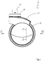
Figuren 6 und7 Stirnansichten der Einradrolle 10 einschließlich Tragteilabdeckung 19 gemäß Ansichtspfeilen VI und VII inFig. 4 dargestellt. -
- 10
- Einradrolle
- 11
- Tragteil
- 12
- Kopfteil
- 13
- Fußteil
- 14
- Radachse
- 15
- Rad
- 16
- Lagerabdeckkappe
- 17
- Befestigungsbolzen
- 18
- Aufnahmebereiche für Rastmittel
- 19
- Tragteilabdeckung
- 20
- Radabdeckungsbereiche
- 21
- Tragteilabdeckungsbereich
- 22
- flexibles Mittelteil
- 23
- Rastelemente
- 24
- Stützbereiche
- 25
- Rastvorsprung
Claims (3)
- Rolle (10) für Apparate und Möbel, mit einem ein Kopfteil (12) und ein Fußteil (13) aufweisendes Tragteil (11), dessen Kopfteil (12) einen Befestigungsbolzen (17) aufnimmt und dessen Fußteil (13) eine Radachse (14) lagert, an der mindestens ein Rad (15) angeordnet ist und dass am Tragteil (11) weitgehend umlaufend eine einstückige, eine durchgehende Designfläche ausbildende Tragteilabdeckung (19) aus Kunststoff austauschbar angeordnet ist, dadurch gekennzeichnet, dass die Innenflächen der Tragteilabdeckung (19) im Bereich der Radabdeckungsbereiche (20) und der Tragteilabdeckungsbereiche (21) je zwei Rastelemente (23) aufweisen, die im montierten Zustand im Tragteil (11) verrastet werden und dass die Innenflächen der Radabdeckungsbereiche (20) jeweils mit zwei Stützbereichen (24) versehen sind, die formschlüssig nach der Befestigung der Tragteilabdeckung ins Tragteil eingreifen.
- Rolle (10) nach Anspruch 1, dadurch gekennzeichnet, dass die Tragteilabdeckung (19) aus Polypropylen gebildet wird.
- Rolle (10) nach Anspruch 1 oder 2, dadurch gekennzeichnet, dass die Tragteilabdeckung (19) mittels einer Mehrzahl von Rastmitteln (23) auf das Tragteil (11) aufrastbar ist.
Applications Claiming Priority (1)
| Application Number | Priority Date | Filing Date | Title |
|---|---|---|---|
| DE102019102175.8A DE102019102175B4 (de) | 2019-01-29 | 2019-01-29 | Rolle für Apparate, Möbel, mit einem ein Kopfteil und ein Fußteil aufweisendes Tragteil |
Publications (2)
| Publication Number | Publication Date |
|---|---|
| EP3689186A1 EP3689186A1 (de) | 2020-08-05 |
| EP3689186B1 true EP3689186B1 (de) | 2022-06-22 |
Family
ID=69174409
Family Applications (1)
| Application Number | Title | Priority Date | Filing Date |
|---|---|---|---|
| EP20152223.2A Active EP3689186B1 (de) | 2019-01-29 | 2020-01-16 | Rolle für apparate, möbel, mit einem ein kopfteil und ein fussteil aufweisendes tragteil |
Country Status (4)
| Country | Link |
|---|---|
| US (1) | US11135873B2 (de) |
| EP (1) | EP3689186B1 (de) |
| DE (1) | DE102019102175B4 (de) |
| PL (1) | PL3689186T3 (de) |
Families Citing this family (2)
| Publication number | Priority date | Publication date | Assignee | Title |
|---|---|---|---|---|
| NO20210365A1 (en) * | 2021-03-22 | 2022-08-29 | Wheel Me As | A rolling device with releasably arranged wheel |
| US11628687B1 (en) * | 2021-07-01 | 2023-04-18 | Andre Kafeleh Coates | Protective covering for caster assembly |
Family Cites Families (14)
| Publication number | Priority date | Publication date | Assignee | Title |
|---|---|---|---|---|
| US2483241A (en) * | 1946-02-27 | 1949-09-27 | Prec Metal Workers | Caster guard |
| US3166780A (en) * | 1961-06-02 | 1965-01-26 | Nagel Chase Mfg Company | Caster construction |
| US3486185A (en) * | 1967-03-27 | 1969-12-30 | Gerhard Lange | Caster cover |
| USD326221S (en) * | 1989-11-15 | 1992-05-19 | Stryker Corporation | Caster cover |
| US5123143A (en) * | 1991-04-08 | 1992-06-23 | Carmack David W | Castor cover |
| US5371920A (en) * | 1993-01-21 | 1994-12-13 | Rainville; Donald | Safety system of roll guards |
| US6125504A (en) * | 1998-09-21 | 2000-10-03 | Richards; Tammy L. | Chair caster cover |
| JP2000203207A (ja) * | 1999-01-12 | 2000-07-25 | Hammer Caster Kk | キャスタ―カバ― |
| JP2001161755A (ja) * | 1999-12-10 | 2001-06-19 | Akira Usui | 車椅子の段差乗り越え装置 |
| JP3617006B2 (ja) * | 2002-07-31 | 2005-02-02 | ハンマーキャスター株式会社 | キャスターカバー |
| BRMU8701519U2 (pt) * | 2007-07-23 | 2009-03-03 | Metalurgica Schioppa Ltda | disposiÇço construtiva introduzida em carenagem de rodÍzio giratàrio |
| US10442246B2 (en) * | 2017-03-31 | 2019-10-15 | General Electric Company | Obstacle moving device for wheel assembly of mobile device |
| GB2565758A (en) * | 2017-07-19 | 2019-02-27 | Roderick Birch Guy | Cover apparatus |
| GB2561032B (en) * | 2017-08-09 | 2020-10-07 | Davis Nicholas | Castor wheel cover |
-
2019
- 2019-01-29 DE DE102019102175.8A patent/DE102019102175B4/de active Active
-
2020
- 2020-01-16 EP EP20152223.2A patent/EP3689186B1/de active Active
- 2020-01-16 PL PL20152223.2T patent/PL3689186T3/pl unknown
- 2020-01-29 US US16/775,590 patent/US11135873B2/en active Active
Also Published As
| Publication number | Publication date |
|---|---|
| DE102019102175A1 (de) | 2020-07-30 |
| US11135873B2 (en) | 2021-10-05 |
| PL3689186T3 (pl) | 2022-10-17 |
| US20200238757A1 (en) | 2020-07-30 |
| DE102019102175B4 (de) | 2021-01-14 |
| EP3689186A1 (de) | 2020-08-05 |
Similar Documents
| Publication | Publication Date | Title |
|---|---|---|
| DE2721388A1 (de) | Zweiraedrige schwenkrolle, insbesondere fuer moebelfuesse | |
| DE4103328A1 (de) | Laufrolle mit bremsmechanismus | |
| DE3620098A1 (de) | Laufrolle | |
| DE3134179A1 (de) | "stossfeste fussrollenanordung" | |
| DE4102471A1 (de) | Laufrollen | |
| DE60226198T2 (de) | Schwenkbare Laufrolle | |
| DE102019102175B4 (de) | Rolle für Apparate, Möbel, mit einem ein Kopfteil und ein Fußteil aufweisendes Tragteil | |
| EP2467214B1 (de) | Flächenreinigungskopf | |
| EP1038423A1 (de) | Vorrichtung zum Verfestigen des Bodens bei Bodenbearbeitungs- und Sävorgängen mit Hilfe von Stempelwerkzeugen | |
| DE2839344A1 (de) | Fusschutz fuer ein rad oder eine rolle an einem flurfahrzeug | |
| WO2004005050A1 (de) | Laufrolle für einkaufs- und transportwagen | |
| DE1753058A1 (de) | Abdeckblende fuer Schwenkrollen | |
| CH616623A5 (en) | Castor for manually moved vehicles, in particular for shopping trolleys | |
| DE2153324B2 (de) | Schwenkbare Laufrolle, vorzugsweise aus Kunststoff, mit einer senkrechten Schwenkachse | |
| DE9204233U1 (de) | Vorrichtung zur Versäuberung von Porzellanrohlingen zur Herstellung von Puppen | |
| DE102006049071B3 (de) | Rolle, vorzugsweise Lenkrolle für Apparate, Geräte, Möbel oder dergleichen | |
| DE3913722C2 (de) | ||
| DE2262487A1 (de) | Wagenheber | |
| DE2307074C3 (de) | Schleifkopf mit einer Umfangsschleifscheibe und einer diese teilweise umgebenden Schutzhaube | |
| DE2503964C2 (de) | Standfuß für Waschmaschinen o. dgl. mit Fußteller und beweglichem Schaft | |
| CH604627A5 (en) | Sun-bed supported by legs and roller | |
| DE3815280A1 (de) | Bodenwalze | |
| EP3578416B1 (de) | Vorrichtung zur ladungssicherung | |
| DE69520976T2 (de) | Gerät zum Anbringen von Strichmarkierungen | |
| DE1505772C (de) | Laufrolle an Transportwagen |
Legal Events
| Date | Code | Title | Description |
|---|---|---|---|
| PUAI | Public reference made under article 153(3) epc to a published international application that has entered the european phase |
Free format text: ORIGINAL CODE: 0009012 |
|
| STAA | Information on the status of an ep patent application or granted ep patent |
Free format text: STATUS: REQUEST FOR EXAMINATION WAS MADE |
|
| 17P | Request for examination filed |
Effective date: 20200528 |
|
| AK | Designated contracting states |
Kind code of ref document: A1 Designated state(s): AL AT BE BG CH CY CZ DE DK EE ES FI FR GB GR HR HU IE IS IT LI LT LU LV MC MK MT NL NO PL PT RO RS SE SI SK SM TR |
|
| AX | Request for extension of the european patent |
Extension state: BA ME |
|
| STAA | Information on the status of an ep patent application or granted ep patent |
Free format text: STATUS: EXAMINATION IS IN PROGRESS |
|
| 17Q | First examination report despatched |
Effective date: 20200902 |
|
| GRAP | Despatch of communication of intention to grant a patent |
Free format text: ORIGINAL CODE: EPIDOSNIGR1 |
|
| STAA | Information on the status of an ep patent application or granted ep patent |
Free format text: STATUS: GRANT OF PATENT IS INTENDED |
|
| INTG | Intention to grant announced |
Effective date: 20220307 |
|
| GRAS | Grant fee paid |
Free format text: ORIGINAL CODE: EPIDOSNIGR3 |
|
| GRAA | (expected) grant |
Free format text: ORIGINAL CODE: 0009210 |
|
| STAA | Information on the status of an ep patent application or granted ep patent |
Free format text: STATUS: THE PATENT HAS BEEN GRANTED |
|
| RBV | Designated contracting states (corrected) |
Designated state(s): AL AT BE BG CH CY CZ DK EE ES FI FR GB GR HR HU IE IS IT LI LT LU LV MC MK MT NL NO PL PT RO RS SE SI SK SM TR |
|
| REG | Reference to a national code |
Ref country code: DE Ref legal event code: R108 |
|
| AK | Designated contracting states |
Kind code of ref document: B1 Designated state(s): AL AT BE BG CH CY CZ DK EE ES FI FR GB GR HR HU IE IS IT LI LT LU LV MC MK MT NL NO PL PT RO RS SE SI SK SM TR |
|
| REG | Reference to a national code |
Ref country code: GB Ref legal event code: FG4D Free format text: NOT ENGLISH |
|
| REG | Reference to a national code |
Ref country code: CH Ref legal event code: EP |
|
| REG | Reference to a national code |
Ref country code: AT Ref legal event code: REF Ref document number: 1499226 Country of ref document: AT Kind code of ref document: T Effective date: 20220715 |
|
| REG | Reference to a national code |
Ref country code: IE Ref legal event code: FG4D Free format text: LANGUAGE OF EP DOCUMENT: GERMAN |
|
| REG | Reference to a national code |
Ref country code: LT Ref legal event code: MG9D |
|
| REG | Reference to a national code |
Ref country code: NL Ref legal event code: MP Effective date: 20220622 |
|
| PG25 | Lapsed in a contracting state [announced via postgrant information from national office to epo] |
Ref country code: SE Free format text: LAPSE BECAUSE OF FAILURE TO SUBMIT A TRANSLATION OF THE DESCRIPTION OR TO PAY THE FEE WITHIN THE PRESCRIBED TIME-LIMIT Effective date: 20220622 Ref country code: NO Free format text: LAPSE BECAUSE OF FAILURE TO SUBMIT A TRANSLATION OF THE DESCRIPTION OR TO PAY THE FEE WITHIN THE PRESCRIBED TIME-LIMIT Effective date: 20220922 Ref country code: LT Free format text: LAPSE BECAUSE OF FAILURE TO SUBMIT A TRANSLATION OF THE DESCRIPTION OR TO PAY THE FEE WITHIN THE PRESCRIBED TIME-LIMIT Effective date: 20220622 Ref country code: HR Free format text: LAPSE BECAUSE OF FAILURE TO SUBMIT A TRANSLATION OF THE DESCRIPTION OR TO PAY THE FEE WITHIN THE PRESCRIBED TIME-LIMIT Effective date: 20220622 Ref country code: GR Free format text: LAPSE BECAUSE OF FAILURE TO SUBMIT A TRANSLATION OF THE DESCRIPTION OR TO PAY THE FEE WITHIN THE PRESCRIBED TIME-LIMIT Effective date: 20220923 Ref country code: FI Free format text: LAPSE BECAUSE OF FAILURE TO SUBMIT A TRANSLATION OF THE DESCRIPTION OR TO PAY THE FEE WITHIN THE PRESCRIBED TIME-LIMIT Effective date: 20220622 Ref country code: BG Free format text: LAPSE BECAUSE OF FAILURE TO SUBMIT A TRANSLATION OF THE DESCRIPTION OR TO PAY THE FEE WITHIN THE PRESCRIBED TIME-LIMIT Effective date: 20220922 |
|
| PG25 | Lapsed in a contracting state [announced via postgrant information from national office to epo] |
Ref country code: RS Free format text: LAPSE BECAUSE OF FAILURE TO SUBMIT A TRANSLATION OF THE DESCRIPTION OR TO PAY THE FEE WITHIN THE PRESCRIBED TIME-LIMIT Effective date: 20220622 Ref country code: LV Free format text: LAPSE BECAUSE OF FAILURE TO SUBMIT A TRANSLATION OF THE DESCRIPTION OR TO PAY THE FEE WITHIN THE PRESCRIBED TIME-LIMIT Effective date: 20220622 |
|
| PG25 | Lapsed in a contracting state [announced via postgrant information from national office to epo] |
Ref country code: NL Free format text: LAPSE BECAUSE OF FAILURE TO SUBMIT A TRANSLATION OF THE DESCRIPTION OR TO PAY THE FEE WITHIN THE PRESCRIBED TIME-LIMIT Effective date: 20220622 |
|
| PG25 | Lapsed in a contracting state [announced via postgrant information from national office to epo] |
Ref country code: SM Free format text: LAPSE BECAUSE OF FAILURE TO SUBMIT A TRANSLATION OF THE DESCRIPTION OR TO PAY THE FEE WITHIN THE PRESCRIBED TIME-LIMIT Effective date: 20220622 Ref country code: SK Free format text: LAPSE BECAUSE OF FAILURE TO SUBMIT A TRANSLATION OF THE DESCRIPTION OR TO PAY THE FEE WITHIN THE PRESCRIBED TIME-LIMIT Effective date: 20220622 Ref country code: RO Free format text: LAPSE BECAUSE OF FAILURE TO SUBMIT A TRANSLATION OF THE DESCRIPTION OR TO PAY THE FEE WITHIN THE PRESCRIBED TIME-LIMIT Effective date: 20220622 Ref country code: PT Free format text: LAPSE BECAUSE OF FAILURE TO SUBMIT A TRANSLATION OF THE DESCRIPTION OR TO PAY THE FEE WITHIN THE PRESCRIBED TIME-LIMIT Effective date: 20221024 Ref country code: ES Free format text: LAPSE BECAUSE OF FAILURE TO SUBMIT A TRANSLATION OF THE DESCRIPTION OR TO PAY THE FEE WITHIN THE PRESCRIBED TIME-LIMIT Effective date: 20220622 Ref country code: EE Free format text: LAPSE BECAUSE OF FAILURE TO SUBMIT A TRANSLATION OF THE DESCRIPTION OR TO PAY THE FEE WITHIN THE PRESCRIBED TIME-LIMIT Effective date: 20220622 |
|
| PG25 | Lapsed in a contracting state [announced via postgrant information from national office to epo] |
Ref country code: IS Free format text: LAPSE BECAUSE OF FAILURE TO SUBMIT A TRANSLATION OF THE DESCRIPTION OR TO PAY THE FEE WITHIN THE PRESCRIBED TIME-LIMIT Effective date: 20221022 |
|
| PG25 | Lapsed in a contracting state [announced via postgrant information from national office to epo] |
Ref country code: AL Free format text: LAPSE BECAUSE OF FAILURE TO SUBMIT A TRANSLATION OF THE DESCRIPTION OR TO PAY THE FEE WITHIN THE PRESCRIBED TIME-LIMIT Effective date: 20220622 |
|
| PG25 | Lapsed in a contracting state [announced via postgrant information from national office to epo] |
Ref country code: DK Free format text: LAPSE BECAUSE OF FAILURE TO SUBMIT A TRANSLATION OF THE DESCRIPTION OR TO PAY THE FEE WITHIN THE PRESCRIBED TIME-LIMIT Effective date: 20220622 |
|
| PLBE | No opposition filed within time limit |
Free format text: ORIGINAL CODE: 0009261 |
|
| STAA | Information on the status of an ep patent application or granted ep patent |
Free format text: STATUS: NO OPPOSITION FILED WITHIN TIME LIMIT |
|
| 26N | No opposition filed |
Effective date: 20230323 |
|
| P01 | Opt-out of the competence of the unified patent court (upc) registered |
Effective date: 20230516 |
|
| P02 | Opt-out of the competence of the unified patent court (upc) changed |
Effective date: 20230517 |
|
| PG25 | Lapsed in a contracting state [announced via postgrant information from national office to epo] |
Ref country code: SI Free format text: LAPSE BECAUSE OF FAILURE TO SUBMIT A TRANSLATION OF THE DESCRIPTION OR TO PAY THE FEE WITHIN THE PRESCRIBED TIME-LIMIT Effective date: 20220622 |
|
| REG | Reference to a national code |
Ref country code: CH Ref legal event code: PL |
|
| PG25 | Lapsed in a contracting state [announced via postgrant information from national office to epo] |
Ref country code: LU Free format text: LAPSE BECAUSE OF NON-PAYMENT OF DUE FEES Effective date: 20230116 |
|
| REG | Reference to a national code |
Ref country code: BE Ref legal event code: MM Effective date: 20230131 |
|
| PG25 | Lapsed in a contracting state [announced via postgrant information from national office to epo] |
Ref country code: LI Free format text: LAPSE BECAUSE OF NON-PAYMENT OF DUE FEES Effective date: 20230131 Ref country code: CH Free format text: LAPSE BECAUSE OF NON-PAYMENT OF DUE FEES Effective date: 20230131 |
|
| PG25 | Lapsed in a contracting state [announced via postgrant information from national office to epo] |
Ref country code: BE Free format text: LAPSE BECAUSE OF NON-PAYMENT OF DUE FEES Effective date: 20230131 |
|
| PG25 | Lapsed in a contracting state [announced via postgrant information from national office to epo] |
Ref country code: IE Free format text: LAPSE BECAUSE OF NON-PAYMENT OF DUE FEES Effective date: 20230116 |
|
| PG25 | Lapsed in a contracting state [announced via postgrant information from national office to epo] |
Ref country code: MC Free format text: LAPSE BECAUSE OF FAILURE TO SUBMIT A TRANSLATION OF THE DESCRIPTION OR TO PAY THE FEE WITHIN THE PRESCRIBED TIME-LIMIT Effective date: 20220622 |
|
| PG25 | Lapsed in a contracting state [announced via postgrant information from national office to epo] |
Ref country code: MC Free format text: LAPSE BECAUSE OF FAILURE TO SUBMIT A TRANSLATION OF THE DESCRIPTION OR TO PAY THE FEE WITHIN THE PRESCRIBED TIME-LIMIT Effective date: 20220622 |
|
| PG25 | Lapsed in a contracting state [announced via postgrant information from national office to epo] |
Ref country code: BG Free format text: LAPSE BECAUSE OF FAILURE TO SUBMIT A TRANSLATION OF THE DESCRIPTION OR TO PAY THE FEE WITHIN THE PRESCRIBED TIME-LIMIT Effective date: 20220622 |
|
| PG25 | Lapsed in a contracting state [announced via postgrant information from national office to epo] |
Ref country code: BG Free format text: LAPSE BECAUSE OF FAILURE TO SUBMIT A TRANSLATION OF THE DESCRIPTION OR TO PAY THE FEE WITHIN THE PRESCRIBED TIME-LIMIT Effective date: 20220622 |
|
| PGFP | Annual fee paid to national office [announced via postgrant information from national office to epo] |
Ref country code: AT Payment date: 20250417 Year of fee payment: 5 |
|
| PG25 | Lapsed in a contracting state [announced via postgrant information from national office to epo] |
Ref country code: CY Free format text: LAPSE BECAUSE OF FAILURE TO SUBMIT A TRANSLATION OF THE DESCRIPTION OR TO PAY THE FEE WITHIN THE PRESCRIBED TIME-LIMIT; INVALID AB INITIO Effective date: 20200116 |
|
| PG25 | Lapsed in a contracting state [announced via postgrant information from national office to epo] |
Ref country code: HU Free format text: LAPSE BECAUSE OF FAILURE TO SUBMIT A TRANSLATION OF THE DESCRIPTION OR TO PAY THE FEE WITHIN THE PRESCRIBED TIME-LIMIT; INVALID AB INITIO Effective date: 20200116 |
|
| REG | Reference to a national code |
Ref country code: AT Ref legal event code: MM01 Ref document number: 1499226 Country of ref document: AT Kind code of ref document: T Effective date: 20250116 |
|
| PGFP | Annual fee paid to national office [announced via postgrant information from national office to epo] |
Ref country code: GB Payment date: 20260122 Year of fee payment: 7 |
|
| PG25 | Lapsed in a contracting state [announced via postgrant information from national office to epo] |
Ref country code: AT Free format text: LAPSE BECAUSE OF NON-PAYMENT OF DUE FEES Effective date: 20250116 |
|
| PGFP | Annual fee paid to national office [announced via postgrant information from national office to epo] |
Ref country code: IT Payment date: 20260130 Year of fee payment: 7 |
|
| PGFP | Annual fee paid to national office [announced via postgrant information from national office to epo] |
Ref country code: FR Payment date: 20260127 Year of fee payment: 7 |
|
| PGFP | Annual fee paid to national office [announced via postgrant information from national office to epo] |
Ref country code: TR Payment date: 20260115 Year of fee payment: 7 |
|
| PGFP | Annual fee paid to national office [announced via postgrant information from national office to epo] |
Ref country code: CZ Payment date: 20260102 Year of fee payment: 7 |
|
| PGFP | Annual fee paid to national office [announced via postgrant information from national office to epo] |
Ref country code: PL Payment date: 20260107 Year of fee payment: 7 |