EP3688438B1 - Vorrichtung und verfahren zur unterscheidung eines aus einem leck austretenden prüfgases von störgas - Google Patents
Vorrichtung und verfahren zur unterscheidung eines aus einem leck austretenden prüfgases von störgas Download PDFInfo
- Publication number
- EP3688438B1 EP3688438B1 EP18780098.2A EP18780098A EP3688438B1 EP 3688438 B1 EP3688438 B1 EP 3688438B1 EP 18780098 A EP18780098 A EP 18780098A EP 3688438 B1 EP3688438 B1 EP 3688438B1
- Authority
- EP
- European Patent Office
- Prior art keywords
- gas
- test
- sensor
- flow
- suctioned
- Prior art date
- Legal status (The legal status is an assumption and is not a legal conclusion. Google has not performed a legal analysis and makes no representation as to the accuracy of the status listed.)
- Active
Links
- 238000000034 method Methods 0.000 title claims description 13
- 230000002452 interceptive effect Effects 0.000 title claims description 12
- 238000005259 measurement Methods 0.000 claims description 11
- 238000011156 evaluation Methods 0.000 claims description 10
- 238000001514 detection method Methods 0.000 claims description 7
- 230000000737 periodic effect Effects 0.000 claims 1
- 239000007789 gas Substances 0.000 description 218
- 239000000523 sample Substances 0.000 description 21
- 239000000700 radioactive tracer Substances 0.000 description 7
- 238000011144 upstream manufacturing Methods 0.000 description 6
- 238000010521 absorption reaction Methods 0.000 description 4
- 239000000203 mixture Substances 0.000 description 4
- 238000011010 flushing procedure Methods 0.000 description 2
- 238000005086 pumping Methods 0.000 description 2
- 238000002485 combustion reaction Methods 0.000 description 1
- 230000004069 differentiation Effects 0.000 description 1
- 230000000694 effects Effects 0.000 description 1
- 239000001307 helium Substances 0.000 description 1
- 229910052734 helium Inorganic materials 0.000 description 1
- SWQJXJOGLNCZEY-UHFFFAOYSA-N helium atom Chemical compound [He] SWQJXJOGLNCZEY-UHFFFAOYSA-N 0.000 description 1
- 239000003550 marker Substances 0.000 description 1
- 230000037361 pathway Effects 0.000 description 1
- 238000010926 purge Methods 0.000 description 1
- 230000005855 radiation Effects 0.000 description 1
- 239000003507 refrigerant Substances 0.000 description 1
- 230000029058 respiratory gaseous exchange Effects 0.000 description 1
Images


Classifications
-
- G—PHYSICS
- G01—MEASURING; TESTING
- G01M—TESTING STATIC OR DYNAMIC BALANCE OF MACHINES OR STRUCTURES; TESTING OF STRUCTURES OR APPARATUS, NOT OTHERWISE PROVIDED FOR
- G01M3/00—Investigating fluid-tightness of structures
- G01M3/02—Investigating fluid-tightness of structures by using fluid or vacuum
- G01M3/04—Investigating fluid-tightness of structures by using fluid or vacuum by detecting the presence of fluid at the leakage point
- G01M3/20—Investigating fluid-tightness of structures by using fluid or vacuum by detecting the presence of fluid at the leakage point using special tracer materials, e.g. dye, fluorescent material, radioactive material
- G01M3/22—Investigating fluid-tightness of structures by using fluid or vacuum by detecting the presence of fluid at the leakage point using special tracer materials, e.g. dye, fluorescent material, radioactive material for pipes, cables or tubes; for pipe joints or seals; for valves; for welds; for containers, e.g. radiators
- G01M3/222—Investigating fluid-tightness of structures by using fluid or vacuum by detecting the presence of fluid at the leakage point using special tracer materials, e.g. dye, fluorescent material, radioactive material for pipes, cables or tubes; for pipe joints or seals; for valves; for welds; for containers, e.g. radiators for tubes
-
- G—PHYSICS
- G01—MEASURING; TESTING
- G01M—TESTING STATIC OR DYNAMIC BALANCE OF MACHINES OR STRUCTURES; TESTING OF STRUCTURES OR APPARATUS, NOT OTHERWISE PROVIDED FOR
- G01M3/00—Investigating fluid-tightness of structures
- G01M3/02—Investigating fluid-tightness of structures by using fluid or vacuum
- G01M3/04—Investigating fluid-tightness of structures by using fluid or vacuum by detecting the presence of fluid at the leakage point
- G01M3/20—Investigating fluid-tightness of structures by using fluid or vacuum by detecting the presence of fluid at the leakage point using special tracer materials, e.g. dye, fluorescent material, radioactive material
- G01M3/202—Investigating fluid-tightness of structures by using fluid or vacuum by detecting the presence of fluid at the leakage point using special tracer materials, e.g. dye, fluorescent material, radioactive material using mass spectrometer detection systems
- G01M3/205—Accessories or associated equipment; Pump constructions
Definitions
- the invention relates to a method for distinguishing a test gas escaping from a test object from interfering gas in the vicinity of the test object during sniffer leak detection.
- the invention also relates to a corresponding sniffer leak detector.
- a test piece to be examined for a leak is filled with a test gas, for example helium or CO 2 , and is subjected to a pressure that is greater than the pressure in the external atmosphere surrounding the test piece.
- a test gas for example helium or CO 2
- the tracer gas escapes from the test item and can be measured in the external environment of the test item.
- the external environment in particular the outer surface of the test object, is examined with a sniffer probe.
- the sniffer probe has a suction opening for sucking in a gas stream.
- the intake opening is connected via a gas line to a sensor and a gas pump that generates the gas flow.
- the sensor is designed to detect the test gas partial pressure of the test gas in the sucked-in gas flow.
- test gas partial pressure is the share of the pressure of the test gas in the total pressure of the sucked in and pumped gas mixture.
- a typical test gas partial pressure sensor is a gas analyzer, such as a mass spectrometer/mass spectroscope or an infrared radiation absorption cell.
- the atmosphere surrounding the test specimen can have gas components that correspond to the test gas or that result in a measurement signal that corresponds to the measurement signal of the test gas.
- these gas components are referred to as interfering gas because they falsify the measurement result and interfere with the leak detection.
- the test object to be examined can be a heat exchanger that is filled with CO 2 as a refrigerant.
- the CO 2 serves as a test gas.
- CO 2 can occur in the form of breathing gas from the person using the sniffer probe or as exhaust gas from a combustion engine.
- the test gas is detected using the infrared absorption method or a mass spectroscopic detection, there may be cross-sensitivities to similar or similar gases from the test object environment.
- the test gas escaping from a leak is distinguished from interfering gas in the test object environment by using a sniffer probe with two separate suction openings.
- the one The suction opening is used to suck in the test gas and the other suction opening is used for reference measurement at a distance from the suction opening.
- the gas composition in the test object environment is examined for the presence of test gas.
- leak detectors are described, for example, in EP 1342070 B1 and EP 22384422 B1 . Due to the distance between the two suction openings for the test gas search and for the reference measurement, the gas for the reference measurement is not taken in at the location of the test gas suction, which has a negative effect on the measurement result.
- the invention is based on the object of improving the differentiation of a test gas escaping from a leak in a test object from interfering gas in the vicinity of the test object during sniffer leak detection.
- test gas leak detector to modulate the gas flow through the gas inlet in order to suppress interference from the vacuum pump of the mass spectrometer.
- the test gas leak detector described is designed for vacuum operation and is not suitable as a sniffer leak detector for operation at atmospheric ambient pressure.
- the total pressure of the gas at the gas detector is proportional to the ratio of the gas flow of the pumped gas and the pumping speed. It is therefore not possible to assess whether the measured test gas partial pressure originates from interfering gas in the environment of the test object or from test gas that has escaped from a leak in the test object. Rather, only interference from within the measuring system can be eliminated, such as interference caused by fluctuations in the pumping speed of the backing pump.
- EP 1 555 520 A1 describes a leak detector with a gas probe and a switching valve that alternately connects the gas probe to a gas inlet and a gas outlet in order to purge the probe with gas drawn in through the outlet.
- DE 10 2010 007 417 A1 describes a leak test device with a measuring connection, an outside air connection and a reservoir in which a flushing gas for flushing the sensor is contained.
- JP 2001050852 A describes a sniffer probe having a gas inlet and a cylindrical cover surrounding the gas inlet.
- WO 2009/051530 A1 describes a leak detection system having a sniffer probe and a detector configured to detect a marker present in the vicinity of the sniffer probe.
- the method according to the invention is defined by the features of claim 1.
- the device according to the invention is defined by the features of claim 8.
- the invention is based on the idea of periodically and repeatedly varying the current strength of the gas flow sucked into the sniffer probe through the suction opening and thereby keeping the total pressure of the gas sucked in with the sniffer probe at the sensor as constant as possible. Fluctuations in the total pressure of more than 10 percent should be avoided.
- the total pressure of the gas in the vicinity of the test object in the area of the sniffer probe is approximately atmospheric pressure and the total pressure at the sensor should preferably be set to a value of at least 80 percent of the total pressure in the test object environment in the area of the sniffer probe. In this area, the relationship between gas flow and gas pressure is approximately linear.
- P test gas Q leak Q Flow + c 0 ⁇ P total
- P test gas the test gas partial pressure measured with the sensor
- P total the total pressure at the sensor
- Q leak the gas flow through the leak (leak rate)
- Q flow the flow rate of the gas at the sensor
- c o the test gas concentration in the atmosphere surrounding the test object (interfering gas) is.
- the test gas partial pressure is approximately constant and negligibly variable. If no tracer gas escapes from a leak, the tracer gas partial pressure results from the constant concentration of the interfering gas that corresponds to or at least resembles the tracer gas (e.g. in the case of infrared absorption) and that is present in the atmosphere surrounding the test object. However, if the test gas stream escaping from a leak in the test item is sucked in with the sniffer probe, causes a periodically repeated varying current strength of the sucked-in gas flow a periodically varying portion of the test gas partial pressure at the sensor.
- the sucked-in gas flow is examined to determine whether the measured test gas partial pressure has a varying proportion whose mean amplitude is above a threshold value, i.e. not negligible and follows the varying of the sucked-in gas flow, which means, for example, that the frequency of the varying test gas partial pressure component corresponds to the frequency of the varying current strength of the sucked-in gas flow. If a varying tracer gas partial pressure is above the threshold value, this serves as an indication of a leak in the test object. The evaluation device then indicates that the test item has a leak.
- a total pressure p total (t) of the sucked-in gas flow at the sensor that is as constant as possible is of particular importance for the invention, because only then does an approximately constant proportion of test gas result in the case of a non-existent or negligibly small leak in the test object, i.e. a Test gas proportion whose variation is less than a specified threshold.
- the smallest detectable leak should cause a partial pressure change that is higher than the unavoidable partial pressure fluctuation from the test gas concentration in the surrounding atmosphere.
- the total pressure p total of the gas flow drawn in at the sensor should preferably be in the range between 90 and 110 percent of the total pressure in the atmosphere surrounding the test object in the area of the sniffer probe.
- This can be atmospheric pressure, i.e. the specimen is exposed to the atmosphere and has a pressure inside it that is above atmospheric pressure, while the total pressure at the sensor of the sniffer leak detector is maintained in the range of 90 to 110 percent of atmospheric pressure, which should also show negligible fluctuations, i.e. vary by less than 10 percent target.
- the measurement signal of the current intensity of the sucked-in gas flow can be modulated with a modulation frequency and phase.
- the modulated current intensity signal can be demodulated according to the principle of a lock-in amplifier with a defined frequency and phase reference to the modulation of the current intensity signal. Frequency and phase reference means that the demodulation frequency and phase are a multiple of the modulation frequency and phase.
- An additional comparison measurement can be carried out in which the current strength of the sucked-in gas flow is not varied periodically but is kept constant in order to be able to determine the test gas partial pressure in the atmosphere surrounding the test object.
- the modulation frequency of the modulation of the current strength of the sucked-in gas flow is in the range of 1 Hz - 20 Hz and preferably in the range of 3 Hz - 10 Hz.
- a gas line path which may be a gas line, connects the suction port of the sniffer probe, the sensor, and a gas pump.
- the sensor is designed to determine the test gas partial pressure of the test gas to be detected in the sucked-in gas flow.
- the gas pump generates the gas pressure required to suck in the gas.
- a control device is designed to repeatedly vary the current strength of the sucked-in gas flow and to avoid fluctuations in the total pressure of the gas at the sensor of more than 10 percent.
- An evaluation device is designed to measure and determine whether the test gas partial pressure of test gas contained in the sucked gas stream has a varying component, the average amplitude of which is above the threshold value described above and which follows the variation of the sucked-in gas flow. This can be the case, for example, when the frequency of the varying portion of the test gas partial pressure corresponds to the frequency of the varied gas flow and the phase has a fixed relationship to the phase of the gas flow modulation.
- the control device is preferably designed to set the total pressure of the sucked-in gas flow at the sensor to a value in the range of approximately 80 percent and preferably in the range between 90-110 percent of the total pressure of the gas in the atmosphere surrounding the test specimen. In this area, the relationship between gas flow and gas pressure is approximately linear.
- the control device should be designed to determine the leakage gas flow in relation to a calibration with a known test leak.
- Fluctuations in the total pressure of the gas at the sensor can be suppressed or reduced, for example, by arranging the sensor downstream of the gas pump.
- the gas line path between the intake opening and the sensor can have a throttle.
- the control device can control the delivery rate or speed of the gas pump and/or change the conductance or the flow resistance of the throttle.
- the throttle can be a capillary which has, for example, a length in the range from approx. 2 cm to approx. 1 m and a maximum diameter of approx. 5 mm. However, longer capillaries are also conceivable.
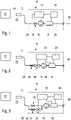
- the sniffer leak detectors 10 of the three in the Figs. 1 to 3 are each connected in a conventional manner to a sniffer probe 12 with a suction opening 14 via a gas line path 20 .
- a gas pump 16 is arranged along the gas line path 20 and generates the atmosphere 23 surrounding the test object 21 for sucking in the gas.
- the gas conduction path 20 also connects the pump 16 to a sensor 18 arranged immediately downstream of the pump 16 in the form of a conventional gas line.
- the sensor 18 is designed to measure the partial pressure of the test gas in the aspirated gas flow.
- the sensor 18 can be an infrared absorption cuvette, for example. It is important that the sensor 18 is designed to determine the test gas partial pressure at approximately atmospheric pressure or at approximately 90-110 percent of atmospheric pressure.
- the test gas partial pressure is the proportion of test gas in the gas mixture of the sucked-in gas flow. The partial pressure of the test gas can therefore not be measured with a pressure sensor.
- a pressure sensor only measures the total pressure of a gas mixture.
- the gas conduction path 20 discharges the gas stream via an outlet 36 to the atmosphere.
- the gas conduction path 20 can have a throttle 26 .
- the throttle 26 can, as in 1 shown to be arranged upstream of the gas pump 16 .
- a controller 22 is electronically connected to the gas pump 16 to control the gas pump 16 .
- the control device 22 can be designed to control the speed of the gas pump 16 .
- FIG. 1 shows that the control device 22 can also be connected to the throttle 26 in order to change the conductance of the throttle 26.
- the control device can also be electronically connected to the sensor 18 .
- An evaluation device 24 is electronically connected to the sensor 18 in order to process and evaluate the measurement signal.
- the evaluation device 24 is designed to determine whether the test gas partial pressure of the test gas contained in the aspirated gas flow has a varying proportion.
- the evaluation device 24 can check whether the varying portion of the test gas partial pressure has an average amplitude that is above a threshold value.
- the evaluation device 24 can determine whether the varying proportion of the test gas partial pressure follows the varying of the sucked-in gas flow. This is the case when the frequency of the varying test gas partial pressure corresponds to the frequency of the varied gas flow or a multiple of this frequency.
- the evaluation device 24 can be connected to the control device 22 .
- the control device 22 varies, for example, the current strength of the suctioned gas flow by varying the pump speed. This can be in the form of a modulation, for example according to the principle of the lock-in amplifier take place.
- the evaluation device 24 can carry out an adjustment of the frequency of a varying test gas partial pressure with the modulation frequency of the sucked-in gas flow.
- the evaluation device 24 is also designed to determine the leakage current of a known leak with a known leak rate as part of a calibration.
- the control device 22 of the first exemplary embodiment is also designed to set the total pressure of the sucked-in gas flow in the area of the sensor 18 to at least approximately 90-110 percent of the total pressure of the gas in the atmosphere 23 surrounding the test object 21 .
- the relationship between gas flow and gas pressure in this pressure range is approximately linear.
- the total pressure of the sucked-in gas flow at the sensor 18 can be set by controlling the speed of the gas pump 16 and/or by controlling the conductance of the throttle 26 .
- the exemplary embodiments relate to sensors arranged directly downstream of the gas pump 16 . With this arrangement, fluctuations in the total pressure of the gas at the sensor 18 are reduced. Alternatively, however, it is also possible to arrange the sensor 18 upstream of the gas pump 16, ie between the sniffer probe 12 and the gas pump 16.
- the embodiment after 2 differs from the embodiment according to 1 in that a valve 28 that can be controlled via the control device 22 is provided upstream of the gas pump 16 in order to change the line cross section of the gas line path 20 .
- the controllable valve 28 is preferably arranged between the throttle 26 and the gas pump 16 .
- the third exemplary embodiment differs from the second exemplary embodiment in that a bypass 30 bridges the gas line path 20 between the sniffer probe 12 and the gas pump 16 and in particular the throttle 26 .
- the bypass 30 is provided with a choke 34 whose conductance is much greater than the conductance of the choke 26 .
- the bypass line 30 has a controllable valve 32 which is electronically connected to the control device 22 to control it. When increasing the conductance of the valve 32, the gas flow in the bypassed gas line path 20 is reduced. When reducing the conductance of the valve 32, the gas flow in the bypassed gas pathway 20 is increased. In this way, with the aid of the control device 22 and the controlled valve 32 of the bypass line 30, the current strength of the sucked-in gas flow can be varied.
- the restrictor 26 can be a capillary, the length of which is in the range from about 2 cm to about 10 cm and the maximum diameter of which is about 5 mm.
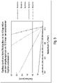
- the resulting gas flow in sccn standard cubic centimeters per minute, cm 3 /min
- the pressure P 2 plotted on the horizontal axis is the pressure P 2 within the gas line path 20 downstream of the gas pump 16 in the area of the sensor 18.
- the ambient pressure in the surroundings 23 of the test specimen 21 is 1013 mbar (atmospheric pressure).
- atmospheric pressure is understood to mean a pressure which can be in the range from approx. 900 mbar to approx. 1100 mbar.
- FIG 4 shows the course of the gas flows that occur for different diameters d of the capillary of the throttle 26 in the range between 0 mbar and 1000 mbar.
- the length of the capillary is 5 cm.
- figure 5 shows the progressions according to 4 in the pressure range between 950 and 1015 mbar.
- the relationship between gas flow and gas pressure is approximately linear if the pressure is at least 950 mbar. It is therefore advantageous according to the invention if the total pressure of the sucked-in gas flow at the sensor 18 is set to a value in the range between approximately 90% and 110% of the total pressure in the area surrounding the test object 21 . It is of particular importance that the change in total pressure is negligible and thus causes a large change in flow.
- the flow changes by a factor of 2 from 100 sccn to 50 sccn.
- This aspect differs from the applications in the vacuum area, as for example in DE 4408877 A1 / EP 7050738 B1 are described. If the pressure P 2 at the location of the sensor 18 is very low, such as in vacuum leak detectors, a change in pressure, for example from 0.1 mbar to 50 mbar, affects the gas flow only slightly.
- a typical leak in the test object 21 can cause a leakage gas flow of 1 ⁇ 10 4 mbar ⁇ l/s.
- the flow or current strength of the sucked-in gas flow is modulated in the range between 120 sccm and 12 sccm with a modulation frequency of 6 Hz.
- the total pressure varies with the modulation frequency between 1000 mbar and 950 mbar.
- the ambient concentration co can be 400 ppm.
- the total pressure fluctuation of 50 mbar is comparatively high. Nevertheless, the partial pressure fluctuation caused by the total pressure fluctuation is small and thus negligible compared to the varying proportion of the partial pressure resulting from the flow modulation. In practice, the total pressure fluctuation is still significantly less than 50 mbar.
- the embodiment after 6 differs from the embodiment according to 1 in that the gas pump 16 is not arranged between the throttle 26 and the sensor 18 in the gas line path 20, but is arranged in the gas line path 20 between the sniffer probe 12 and the throttle 26, i.e. upstream of the throttle 26.
- the embodiment of 7 differs from the embodiment according to 2 in that the gas pump 16 is not arranged between the valve 28 and the sensor 18, but also as in the embodiment according to FIG 6 upstream of the throttle 26.
- the gas pump 16 is not as in 3 between the parallel connection of throttle 26 and valve 32 and the sensor 18, but in the gas line path 20 upstream of the parallel connection of the throttles 26 and 34.
Landscapes
- Physics & Mathematics (AREA)
- General Physics & Mathematics (AREA)
- Examining Or Testing Airtightness (AREA)
- Sampling And Sample Adjustment (AREA)
- Other Investigation Or Analysis Of Materials By Electrical Means (AREA)
Applications Claiming Priority (2)
| Application Number | Priority Date | Filing Date | Title |
|---|---|---|---|
| DE102017217374.2A DE102017217374A1 (de) | 2017-09-29 | 2017-09-29 | Vorrichtung und Verfahren zur Unterscheidung eines aus einem Leck austretenden Prüfgases von Störgas |
| PCT/EP2018/076401 WO2019063761A1 (de) | 2017-09-29 | 2018-09-28 | Vorrichtung und verfahren zur unterscheidung eines aus einem leck austretenden prüfgases von störgas |
Publications (2)
| Publication Number | Publication Date |
|---|---|
| EP3688438A1 EP3688438A1 (de) | 2020-08-05 |
| EP3688438B1 true EP3688438B1 (de) | 2023-01-04 |
Family
ID=63720695
Family Applications (1)
| Application Number | Title | Priority Date | Filing Date |
|---|---|---|---|
| EP18780098.2A Active EP3688438B1 (de) | 2017-09-29 | 2018-09-28 | Vorrichtung und verfahren zur unterscheidung eines aus einem leck austretenden prüfgases von störgas |
Country Status (9)
| Country | Link |
|---|---|
| US (1) | US11199467B2 (ja) |
| EP (1) | EP3688438B1 (ja) |
| JP (1) | JP7150013B2 (ja) |
| CN (1) | CN111183344B (ja) |
| BR (1) | BR112020006319B1 (ja) |
| CA (1) | CA3076439A1 (ja) |
| DE (1) | DE102017217374A1 (ja) |
| MX (1) | MX2020003307A (ja) |
| WO (1) | WO2019063761A1 (ja) |
Families Citing this family (1)
| Publication number | Priority date | Publication date | Assignee | Title |
|---|---|---|---|---|
| KR102356976B1 (ko) * | 2021-07-08 | 2022-02-08 | 이재홍 | 에어 누설 검사 장비 |
Family Cites Families (20)
| Publication number | Priority date | Publication date | Assignee | Title |
|---|---|---|---|---|
| DE4316196C2 (de) * | 1993-05-14 | 1994-07-28 | Guenter Dr Vos | Verfahren und Vorrichtung zur Gasanalyse |
| DE4408877A1 (de) | 1994-03-16 | 1995-09-21 | Leybold Ag | Testgaslecksucher |
| DE19735250A1 (de) | 1997-08-14 | 1999-02-18 | Leybold Vakuum Gmbh | Verfahren zum Betrieb eines Heliumlecksuchers und für die Durchführung dieses Verfahrens geeigneter Heliumlecksucher |
| JPH11153507A (ja) * | 1997-11-20 | 1999-06-08 | Shimadzu Corp | リークデテクタ |
| JP2001050852A (ja) | 1999-08-04 | 2001-02-23 | Nkk Corp | スニッファープローブ及びそれを用いたガス漏れ試験方法 |
| DE19960174A1 (de) | 1999-12-14 | 2001-06-28 | Leybold Vakuum Gmbh | Verfahren zur Lecksuche und Lecklokalisierung sowie zur Durchführung dieser Verfahren geeignete Vorrichtungen |
| DE10062126A1 (de) | 2000-12-13 | 2002-06-20 | Inficon Gmbh | Verfahren zur Feststellung eines Gases mit Hilfe eines Infrarot-Gasanlaysators sowie für die Durchführung dieser Verfahren geigneter Gasanalysator |
| DE10324596A1 (de) * | 2003-05-30 | 2004-12-16 | Inficon Gmbh | Lecksuchgerät |
| EP1555520B1 (en) | 2004-01-13 | 2007-09-12 | VARIAN S.p.A. | Leak detector |
| DE102004050762A1 (de) * | 2004-10-16 | 2006-04-20 | Inficon Gmbh | Verfahren zur Lecksuche |
| DE102006056215A1 (de) * | 2006-11-29 | 2008-06-05 | Inficon Gmbh | Schnüffellecksuchgerät |
| US20080202210A1 (en) * | 2007-02-28 | 2008-08-28 | Varian, Inc. | Test gas leak detection using a composite membrane |
| EP2208038A4 (en) | 2007-10-15 | 2011-12-14 | Adixen Sensistor Ab | LEAK DETECTION SYSTEM WITH A TRACER GAS DISTRIBUTION UNIT |
| EP2238442A4 (en) | 2008-02-07 | 2014-04-16 | California Inst Of Techn | METHOD AND DEVICE FOR NON-DESTRUCTIVE EVALUATION AND MONITORING OF MATERIALS AND STRUCTURES |
| DE102008008262A1 (de) | 2008-02-08 | 2009-08-13 | Inficon Gmbh | Schnüffellecksucher nach dem Referenzmessprinzip |
| DE102009010064A1 (de) | 2009-02-21 | 2010-08-26 | Inficon Gmbh | Schnüffellecksucher |
| DE102010007417A1 (de) | 2010-02-10 | 2011-08-11 | Inficon GmbH, 50968 | Lecktestgerät |
| DE102013218506A1 (de) | 2013-09-16 | 2015-03-19 | Inficon Gmbh | Schnüffellecksucher mit mehrstufiger Membranpumpe |
| CN106153265B (zh) * | 2016-06-20 | 2018-11-30 | 清华大学 | 一种手持式气体泄漏快速检测装置 |
| CN106706216B (zh) * | 2016-12-12 | 2019-05-10 | 清华大学 | 一种高于环境温度的气体泄漏的非接触检测方法 |
-
2017
- 2017-09-29 DE DE102017217374.2A patent/DE102017217374A1/de active Pending
-
2018
- 2018-09-28 US US16/651,021 patent/US11199467B2/en active Active
- 2018-09-28 JP JP2020517997A patent/JP7150013B2/ja active Active
- 2018-09-28 EP EP18780098.2A patent/EP3688438B1/de active Active
- 2018-09-28 CN CN201880062820.XA patent/CN111183344B/zh active Active
- 2018-09-28 MX MX2020003307A patent/MX2020003307A/es unknown
- 2018-09-28 BR BR112020006319-3A patent/BR112020006319B1/pt active IP Right Grant
- 2018-09-28 WO PCT/EP2018/076401 patent/WO2019063761A1/de unknown
- 2018-09-28 CA CA3076439A patent/CA3076439A1/en active Pending
Also Published As
| Publication number | Publication date |
|---|---|
| DE102017217374A1 (de) | 2019-04-04 |
| RU2020114916A3 (ja) | 2022-03-23 |
| BR112020006319B1 (pt) | 2024-03-12 |
| US11199467B2 (en) | 2021-12-14 |
| CN111183344B (zh) | 2022-04-05 |
| MX2020003307A (es) | 2020-07-28 |
| CN111183344A (zh) | 2020-05-19 |
| BR112020006319A2 (pt) | 2020-09-24 |
| EP3688438A1 (de) | 2020-08-05 |
| US20200271540A1 (en) | 2020-08-27 |
| RU2020114916A (ru) | 2021-10-29 |
| WO2019063761A1 (de) | 2019-04-04 |
| JP7150013B2 (ja) | 2022-10-07 |
| CA3076439A1 (en) | 2019-04-04 |
| JP2020535432A (ja) | 2020-12-03 |
Similar Documents
| Publication | Publication Date | Title |
|---|---|---|
| EP1924833B1 (de) | Lecksuchgerät mit schnüffelsonde | |
| DE602004013199T2 (de) | System und verfahren zur bestimmung der lecksicherheit eines objekts | |
| EP3374746B1 (de) | Druckmessung am prüfgaseinlass | |
| EP3377870B1 (de) | Lecksuche mit sauerstoff | |
| DE102009004363B4 (de) | Leckdetektionsverfahren | |
| DE2926112A1 (de) | Testleck-sonde | |
| EP3788340B1 (de) | Verfahren zum ermitteln der relativen lage eines gaslecks | |
| EP2399112A1 (de) | Schnüffellecksucher | |
| DE19735250A1 (de) | Verfahren zum Betrieb eines Heliumlecksuchers und für die Durchführung dieses Verfahrens geeigneter Heliumlecksucher | |
| WO1996019721A1 (de) | Gegenstrom-schnüffellecksucher | |
| EP2999950B1 (de) | Schnüffellecksucher mit nanoporöser membrane | |
| EP3688438B1 (de) | Vorrichtung und verfahren zur unterscheidung eines aus einem leck austretenden prüfgases von störgas | |
| DE10156205A1 (de) | Testgaslecksuchgerät | |
| EP3359941B1 (de) | Erfassung von prüfgasschwankungen bei der schnüffellecksuche | |
| EP3435053A1 (de) | Verfahren zur lokalisierung von leckstellen | |
| EP1629262A2 (de) | Leckraten-messvorrichtung | |
| WO2024099639A1 (de) | Trägergas-lecksuchsystem und trägergas-lecksuchverfahren zur leckagedetektion an einem prüfling | |
| AT524168B1 (de) | Erkennungsverfahren für eine Erkennung von Leckagegas | |
| WO2023217491A1 (de) | Lecksuchvorrichtung und lecksuchverfahren zur detektion eines gaslecks in einem prüfling | |
| DE102018105528A1 (de) | Druckentkopplungsvorrichtung für Partikelmesssystem und Verfahren zur Druckentkopplung | |
| DE2557716A1 (de) | Verfahren zur entnahme einer gasprobe |
Legal Events
| Date | Code | Title | Description |
|---|---|---|---|
| STAA | Information on the status of an ep patent application or granted ep patent |
Free format text: STATUS: UNKNOWN |
|
| STAA | Information on the status of an ep patent application or granted ep patent |
Free format text: STATUS: THE INTERNATIONAL PUBLICATION HAS BEEN MADE |
|
| PUAI | Public reference made under article 153(3) epc to a published international application that has entered the european phase |
Free format text: ORIGINAL CODE: 0009012 |
|
| STAA | Information on the status of an ep patent application or granted ep patent |
Free format text: STATUS: REQUEST FOR EXAMINATION WAS MADE |
|
| 17P | Request for examination filed |
Effective date: 20200318 |
|
| AK | Designated contracting states |
Kind code of ref document: A1 Designated state(s): AL AT BE BG CH CY CZ DE DK EE ES FI FR GB GR HR HU IE IS IT LI LT LU LV MC MK MT NL NO PL PT RO RS SE SI SK SM TR |
|
| AX | Request for extension of the european patent |
Extension state: BA ME |
|
| DAV | Request for validation of the european patent (deleted) | ||
| DAX | Request for extension of the european patent (deleted) | ||
| GRAP | Despatch of communication of intention to grant a patent |
Free format text: ORIGINAL CODE: EPIDOSNIGR1 |
|
| STAA | Information on the status of an ep patent application or granted ep patent |
Free format text: STATUS: GRANT OF PATENT IS INTENDED |
|
| GRAS | Grant fee paid |
Free format text: ORIGINAL CODE: EPIDOSNIGR3 |
|
| INTG | Intention to grant announced |
Effective date: 20221102 |
|
| RIN1 | Information on inventor provided before grant (corrected) |
Inventor name: WETZIG, DANIEL |
|
| GRAA | (expected) grant |
Free format text: ORIGINAL CODE: 0009210 |
|
| STAA | Information on the status of an ep patent application or granted ep patent |
Free format text: STATUS: THE PATENT HAS BEEN GRANTED |
|
| AK | Designated contracting states |
Kind code of ref document: B1 Designated state(s): AL AT BE BG CH CY CZ DE DK EE ES FI FR GB GR HR HU IE IS IT LI LT LU LV MC MK MT NL NO PL PT RO RS SE SI SK SM TR |
|
| REG | Reference to a national code |
Ref country code: GB Ref legal event code: FG4D Free format text: NOT ENGLISH |
|
| REG | Reference to a national code |
Ref country code: DE Ref legal event code: R096 Ref document number: 502018011372 Country of ref document: DE |
|
| REG | Reference to a national code |
Ref country code: CH Ref legal event code: EP |
|
| REG | Reference to a national code |
Ref country code: AT Ref legal event code: REF Ref document number: 1542259 Country of ref document: AT Kind code of ref document: T Effective date: 20230115 |
|
| REG | Reference to a national code |
Ref country code: IE Ref legal event code: FG4D Free format text: LANGUAGE OF EP DOCUMENT: GERMAN |
|
| REG | Reference to a national code |
Ref country code: LT Ref legal event code: MG9D |
|
| REG | Reference to a national code |
Ref country code: NL Ref legal event code: MP Effective date: 20230104 |
|
| P01 | Opt-out of the competence of the unified patent court (upc) registered |
Effective date: 20230427 |
|
| PG25 | Lapsed in a contracting state [announced via postgrant information from national office to epo] |
Ref country code: NL Free format text: LAPSE BECAUSE OF FAILURE TO SUBMIT A TRANSLATION OF THE DESCRIPTION OR TO PAY THE FEE WITHIN THE PRESCRIBED TIME-LIMIT Effective date: 20230104 |
|
| PG25 | Lapsed in a contracting state [announced via postgrant information from national office to epo] |
Ref country code: RS Free format text: LAPSE BECAUSE OF FAILURE TO SUBMIT A TRANSLATION OF THE DESCRIPTION OR TO PAY THE FEE WITHIN THE PRESCRIBED TIME-LIMIT Effective date: 20230104 Ref country code: PT Free format text: LAPSE BECAUSE OF FAILURE TO SUBMIT A TRANSLATION OF THE DESCRIPTION OR TO PAY THE FEE WITHIN THE PRESCRIBED TIME-LIMIT Effective date: 20230504 Ref country code: NO Free format text: LAPSE BECAUSE OF FAILURE TO SUBMIT A TRANSLATION OF THE DESCRIPTION OR TO PAY THE FEE WITHIN THE PRESCRIBED TIME-LIMIT Effective date: 20230404 Ref country code: LV Free format text: LAPSE BECAUSE OF FAILURE TO SUBMIT A TRANSLATION OF THE DESCRIPTION OR TO PAY THE FEE WITHIN THE PRESCRIBED TIME-LIMIT Effective date: 20230104 Ref country code: LT Free format text: LAPSE BECAUSE OF FAILURE TO SUBMIT A TRANSLATION OF THE DESCRIPTION OR TO PAY THE FEE WITHIN THE PRESCRIBED TIME-LIMIT Effective date: 20230104 Ref country code: HR Free format text: LAPSE BECAUSE OF FAILURE TO SUBMIT A TRANSLATION OF THE DESCRIPTION OR TO PAY THE FEE WITHIN THE PRESCRIBED TIME-LIMIT Effective date: 20230104 Ref country code: ES Free format text: LAPSE BECAUSE OF FAILURE TO SUBMIT A TRANSLATION OF THE DESCRIPTION OR TO PAY THE FEE WITHIN THE PRESCRIBED TIME-LIMIT Effective date: 20230104 |
|
| PG25 | Lapsed in a contracting state [announced via postgrant information from national office to epo] |
Ref country code: SE Free format text: LAPSE BECAUSE OF FAILURE TO SUBMIT A TRANSLATION OF THE DESCRIPTION OR TO PAY THE FEE WITHIN THE PRESCRIBED TIME-LIMIT Effective date: 20230104 Ref country code: PL Free format text: LAPSE BECAUSE OF FAILURE TO SUBMIT A TRANSLATION OF THE DESCRIPTION OR TO PAY THE FEE WITHIN THE PRESCRIBED TIME-LIMIT Effective date: 20230104 Ref country code: IS Free format text: LAPSE BECAUSE OF FAILURE TO SUBMIT A TRANSLATION OF THE DESCRIPTION OR TO PAY THE FEE WITHIN THE PRESCRIBED TIME-LIMIT Effective date: 20230504 Ref country code: GR Free format text: LAPSE BECAUSE OF FAILURE TO SUBMIT A TRANSLATION OF THE DESCRIPTION OR TO PAY THE FEE WITHIN THE PRESCRIBED TIME-LIMIT Effective date: 20230405 Ref country code: FI Free format text: LAPSE BECAUSE OF FAILURE TO SUBMIT A TRANSLATION OF THE DESCRIPTION OR TO PAY THE FEE WITHIN THE PRESCRIBED TIME-LIMIT Effective date: 20230104 |
|
| REG | Reference to a national code |
Ref country code: DE Ref legal event code: R097 Ref document number: 502018011372 Country of ref document: DE |
|
| PG25 | Lapsed in a contracting state [announced via postgrant information from national office to epo] |
Ref country code: SM Free format text: LAPSE BECAUSE OF FAILURE TO SUBMIT A TRANSLATION OF THE DESCRIPTION OR TO PAY THE FEE WITHIN THE PRESCRIBED TIME-LIMIT Effective date: 20230104 Ref country code: RO Free format text: LAPSE BECAUSE OF FAILURE TO SUBMIT A TRANSLATION OF THE DESCRIPTION OR TO PAY THE FEE WITHIN THE PRESCRIBED TIME-LIMIT Effective date: 20230104 Ref country code: EE Free format text: LAPSE BECAUSE OF FAILURE TO SUBMIT A TRANSLATION OF THE DESCRIPTION OR TO PAY THE FEE WITHIN THE PRESCRIBED TIME-LIMIT Effective date: 20230104 Ref country code: DK Free format text: LAPSE BECAUSE OF FAILURE TO SUBMIT A TRANSLATION OF THE DESCRIPTION OR TO PAY THE FEE WITHIN THE PRESCRIBED TIME-LIMIT Effective date: 20230104 Ref country code: CZ Free format text: LAPSE BECAUSE OF FAILURE TO SUBMIT A TRANSLATION OF THE DESCRIPTION OR TO PAY THE FEE WITHIN THE PRESCRIBED TIME-LIMIT Effective date: 20230104 |
|
| PLBE | No opposition filed within time limit |
Free format text: ORIGINAL CODE: 0009261 |
|
| STAA | Information on the status of an ep patent application or granted ep patent |
Free format text: STATUS: NO OPPOSITION FILED WITHIN TIME LIMIT |
|
| PG25 | Lapsed in a contracting state [announced via postgrant information from national office to epo] |
Ref country code: SK Free format text: LAPSE BECAUSE OF FAILURE TO SUBMIT A TRANSLATION OF THE DESCRIPTION OR TO PAY THE FEE WITHIN THE PRESCRIBED TIME-LIMIT Effective date: 20230104 |
|
| PGFP | Annual fee paid to national office [announced via postgrant information from national office to epo] |
Ref country code: FR Payment date: 20230919 Year of fee payment: 6 |
|
| 26N | No opposition filed |
Effective date: 20231005 |
|
| PG25 | Lapsed in a contracting state [announced via postgrant information from national office to epo] |
Ref country code: SI Free format text: LAPSE BECAUSE OF FAILURE TO SUBMIT A TRANSLATION OF THE DESCRIPTION OR TO PAY THE FEE WITHIN THE PRESCRIBED TIME-LIMIT Effective date: 20230104 |
|
| PGFP | Annual fee paid to national office [announced via postgrant information from national office to epo] |
Ref country code: IT Payment date: 20230929 Year of fee payment: 6 Ref country code: DE Payment date: 20230928 Year of fee payment: 6 |
|
| REG | Reference to a national code |
Ref country code: CH Ref legal event code: PL |
|
| PG25 | Lapsed in a contracting state [announced via postgrant information from national office to epo] |
Ref country code: LU Free format text: LAPSE BECAUSE OF NON-PAYMENT OF DUE FEES Effective date: 20230928 |