EP3686112B1 - Dispositif de préhension pour récipients de boisson et procédé de fabrication d'un dispositif de préhension - Google Patents
Dispositif de préhension pour récipients de boisson et procédé de fabrication d'un dispositif de préhension Download PDFInfo
- Publication number
- EP3686112B1 EP3686112B1 EP19203606.9A EP19203606A EP3686112B1 EP 3686112 B1 EP3686112 B1 EP 3686112B1 EP 19203606 A EP19203606 A EP 19203606A EP 3686112 B1 EP3686112 B1 EP 3686112B1
- Authority
- EP
- European Patent Office
- Prior art keywords
- spring
- gripping
- suspension
- designed
- gripping device
- Prior art date
- Legal status (The legal status is an assumption and is not a legal conclusion. Google has not performed a legal analysis and makes no representation as to the accuracy of the status listed.)
- Active
Links
Images


Classifications
-
- B—PERFORMING OPERATIONS; TRANSPORTING
- B65—CONVEYING; PACKING; STORING; HANDLING THIN OR FILAMENTARY MATERIAL
- B65B—MACHINES, APPARATUS OR DEVICES FOR, OR METHODS OF, PACKAGING ARTICLES OR MATERIALS; UNPACKING
- B65B21/00—Packaging or unpacking of bottles
- B65B21/02—Packaging or unpacking of bottles in or from preformed containers, e.g. crates
- B65B21/14—Introducing or removing groups of bottles, for filling or emptying containers in one operation
- B65B21/18—Introducing or removing groups of bottles, for filling or emptying containers in one operation using grippers engaging bottles, e.g. bottle necks
- B65B21/186—Inflatable grippers
-
- B—PERFORMING OPERATIONS; TRANSPORTING
- B25—HAND TOOLS; PORTABLE POWER-DRIVEN TOOLS; MANIPULATORS
- B25J—MANIPULATORS; CHAMBERS PROVIDED WITH MANIPULATION DEVICES
- B25J15/00—Gripping heads and other end effectors
- B25J15/0023—Gripper surfaces directly activated by a fluid
-
- B—PERFORMING OPERATIONS; TRANSPORTING
- B25—HAND TOOLS; PORTABLE POWER-DRIVEN TOOLS; MANIPULATORS
- B25J—MANIPULATORS; CHAMBERS PROVIDED WITH MANIPULATION DEVICES
- B25J15/00—Gripping heads and other end effectors
- B25J15/0052—Gripping heads and other end effectors multiple gripper units or multiple end effectors
-
- B—PERFORMING OPERATIONS; TRANSPORTING
- B25—HAND TOOLS; PORTABLE POWER-DRIVEN TOOLS; MANIPULATORS
- B25J—MANIPULATORS; CHAMBERS PROVIDED WITH MANIPULATION DEVICES
- B25J19/00—Accessories fitted to manipulators, e.g. for monitoring, for viewing; Safety devices combined with or specially adapted for use in connection with manipulators
- B25J19/0025—Means for supplying energy to the end effector
- B25J19/0029—Means for supplying energy to the end effector arranged within the different robot elements
-
- B—PERFORMING OPERATIONS; TRANSPORTING
- B65—CONVEYING; PACKING; STORING; HANDLING THIN OR FILAMENTARY MATERIAL
- B65B—MACHINES, APPARATUS OR DEVICES FOR, OR METHODS OF, PACKAGING ARTICLES OR MATERIALS; UNPACKING
- B65B21/00—Packaging or unpacking of bottles
- B65B21/02—Packaging or unpacking of bottles in or from preformed containers, e.g. crates
- B65B21/08—Introducing or removing single bottles, or groups of bottles, e.g. for progressive filling or emptying of containers
- B65B21/12—Introducing or removing single bottles, or groups of bottles, e.g. for progressive filling or emptying of containers using grippers engaging bottles, e.g. bottle necks
-
- B—PERFORMING OPERATIONS; TRANSPORTING
- B65—CONVEYING; PACKING; STORING; HANDLING THIN OR FILAMENTARY MATERIAL
- B65B—MACHINES, APPARATUS OR DEVICES FOR, OR METHODS OF, PACKAGING ARTICLES OR MATERIALS; UNPACKING
- B65B35/00—Supplying, feeding, arranging or orientating articles to be packaged
- B65B35/10—Feeding, e.g. conveying, single articles
- B65B35/16—Feeding, e.g. conveying, single articles by grippers
- B65B35/18—Feeding, e.g. conveying, single articles by grippers by suction-operated grippers
-
- B—PERFORMING OPERATIONS; TRANSPORTING
- B65—CONVEYING; PACKING; STORING; HANDLING THIN OR FILAMENTARY MATERIAL
- B65G—TRANSPORT OR STORAGE DEVICES, e.g. CONVEYORS FOR LOADING OR TIPPING, SHOP CONVEYOR SYSTEMS OR PNEUMATIC TUBE CONVEYORS
- B65G47/00—Article or material-handling devices associated with conveyors; Methods employing such devices
- B65G47/74—Feeding, transfer, or discharging devices of particular kinds or types
- B65G47/90—Devices for picking-up and depositing articles or materials
- B65G47/908—Devices for picking-up and depositing articles or materials with inflatable picking-up means
Definitions
- the present invention relates to a gripping device for beverage containers and a method for producing a gripping device for beverage containers.
- packing or gripping tulips are used to handle articles such as containers, in particular bottles.
- the handling can, for example, provide for articles, such as containers, in particular bottles, to be moved from one location to another or to be placed in an outer packaging, for example a cardboard box or a beverage crate.
- An article or a beverage container which can be received by means of gripping tulips known from the prior art has a lateral lateral surface which normally tapers in the area of an upper neck section.
- Such a beverage container or such a beverage bottle can be closed by a lid at an overhead end area.
- a gripping tulip In order to move articles such as beverage bottles by means of gripping tulips or to insert them into outer packaging, a gripping tulip is lowered onto an article when it is gripped on the head side, until the gripping means at least partially encompasses an upper part of the outer surface of the article provided as a contact section .
- the gripping tulip By actuating or activating gripping elements of the gripping tulip, the article is then fixed to the gripping tulip in question, but can, if necessary, also be detached from the gripping tulip. If the gripping tulip is raised, the article attached to the gripping tulip is also raised together with the gripping tulip.
- a gripping tulip for the head-side gripping of bottles that can be closed in particular by corks, crown caps, screw or clip closures.
- This known gripping tulip has in a pot-shaped housing a sleeve-shaped, elastically deformable insert supported with its front end on the pot rim of the housing and an actuating piston acting on the insert at its rear end with an axial compressive force.
- the housing of the gripping tulip is formed in the front area by a radially outwardly elastically deformable wall.
- US 2016/0096278 A1 discloses a suction instrument with a connecting means, a rubber base and a bellows, which bellows has a projection and is arranged over this projection in a recess of the connecting means.
- the suction device can be used to accept items using negative pressure.
- the gripping instrument comprises a sleeve into which a bottle holder is dipped for receiving.
- a column that is flexible is connected to the sleeve.
- the column is further arranged on a frame.
- the CN 202 107 099 U discloses a gripping tulip, the gripping means of which comprise two oppositely arranged bilateral levers. Each of the two bilateral levers can be pivoted about one of two parallel horizontal axes. A lower lever arm of each bilateral lever, which is provided for gripping an article, is designed as a gripping jaw. An upper lever arm of each bilateral lever, which is provided for the action of a wedge movable up and down by means of an actuating device, is connected to a spring. By inserting a wedge that can be moved up and down via the actuating device between the upper parts of the two bilateral levers, the gripping jaws move towards each other like pliers in order to grip an article on the head side and finally to reach the holding position. Retraction of the wedge causes the gripping jaws to open and thus a gripped article to be released.
- a gripping tulip which also uses a wedge effect to reach a holding position of its gripping means designed as gripping jaws. Since the wedge interacts with a subsequent section, which can be switched between two mechanically stable states, holding positions free of actuation force are made possible in each case.
- this gripping tulip can assume a holding position that is to be maintained without force.
- the DE 10 2012 101 554 A1 discloses a further gripping tulip, the gripping means of which comprise at least three gripping tongues encompassing the contact section of an article at approximately the same height on all sides.
- Each of the gripping tongues is suspended pivotably or elastically on a holding frame of the gripping tulip and is supported there. At their end faces facing away from the holding frame, the gripping tongues each point inwardly toward one another towards the contact section.
- the gripping tongues are raised by lowering the gripping tulip on the head side parallel to the height of an article extending normally to the base surface over a neck section of the article against elastic restoring forces pushed apart obliquely upwards and each brought into an angular position to the holding frame, the end faces of the gripping tongues being supported in a form-fitting and / or force-fitting manner against the contact section of the article.
- a primary object of the invention can therefore be seen in providing a gripping device and a corresponding method for producing a gripping device, by means of which the problems mentioned can be avoided or at least reduced.
- the invention relates to a gripping device for articles such as, in particular, beverage containers.
- the beverage containers which can be received by means of the gripping device can in particular be glass bottles.
- the beverage containers which can be received by means of the gripping device can, however, in particular also be PET bottles.
- Mixed forms, i.e. bottles made from a mix of materials, can also count as articles or beverage containers within the meaning of the definition of the present invention.
- the gripping device comprises a suspension and at least one gripping means which can receive a beverage container by means of compressed air or by means of overpressure or underpressure.
- a pressure medium such as in particular compressed air is meant which is used to generate a suction effect or a gripping effect in the Gripping device is used. Since the gripping device according to the invention can work with both negative and positive pressure, and since a compressible and inexpensively available gas such as compressed air is used as the pressure medium, compressed air is often used in general terms in the further context of the description and the claims.
- the suspension of the gripping device can be designed as a plate which, for example, has two opposite and possibly square-shaped broad side surfaces. If the gripping device comprises several gripping means or at least one first gripping means as well as at least one second gripping means, the suspension can be positioned above the at least one first gripping means and the at least one second gripping means, with edge regions of the suspension the at least one first gripping means and the at least one second Gripping means protrude laterally, or wherein edge regions of the suspension extend laterally beyond the at least one first gripping means and the at least one second gripping means.
- the gripping device further comprises at least one spring, via which the at least one gripping means is connected to the suspension.
- each spring of the gripping device is assigned its own flange, for example, have proven successful.
- the respective flange of its own can optionally be arranged on a lower end region of the spring. It is conceivable here that a gripping means provided for receiving a beverage container with compressed air (underpressure or overpressure) can be releasably attached to a respective flange of its own.
- the respective flange and the respective gripping means interact via latching and / or snap and / or clamping connections in order to releasably attach the respective gripping means to the respective flange.
- embodiments have proven to be useful in which a respective gripping means can be attached to the respective flange.
- the at least one gripping means can be designed in such a way that the at least one gripping means is controlled via compressed air (negative pressure or overpressure) and, as a result, fixes or receives a respective beverage container mechanically and possibly by means of a gripping jaw and / or by means of a lever.
- compressed air negative pressure or overpressure
- embodiments have proven to be useful in which a negative pressure or positive pressure is transmitted to the at least one gripping means, the respective beverage container being sucked in by means of the negative pressure or positive pressure transferred to the respective gripping means and held at the respective gripping means.
- the at least one spring is designed, at least in some areas, as a hollow shaft or as a curved hollow tube. It is conceivable that the at least one gripping means for receiving the beverage container can be acted upon with compressed air (underpressure or overpressure) via the hollow shaft or via the curved hollow tube. As an alternative or in addition to this, it is also conceivable that electrical line connections of the gripping device, hydraulic components and / or sensor components, which are designed as part of the gripping device, are introduced into the hollow shaft or into the curved hollow tube of the at least one spring. Due to the design as a hollow shaft or as a curved hollow tube and the pressurization of the beverage container or the introduction of further components of the gripping device into the hollow shaft or into the curved hollow tube, the gripping device has a clear and compact structure.
- the at least one spring is designed completely or continuously along its course as a hollow shaft or as a hollow tube, via which hollow shaft the at least one gripping means for receiving the beverage container can be acted upon with compressed air (negative pressure or positive pressure).
- the at least one gripping means is controlled differently than by compressed air, for example by an electric motor, electromagnetic or by means of a piezo element or the like the provides at least one gripping means.
- the spring can optionally be designed as a hollow shaft or as a solid shaft. Since a compressed air supply for the spring is not required in this variant, so that the spring does not have to serve as a line for compressed air, the force or energy transmission for the control of the gripping means can take place in other ways, for example by means of electrical lines that are wound around the spring or molded into this are. Manufacturing processes in which foil-like electrical lines are routed to the outer surfaces of the spring and firmly attached there are also conceivable.
- each spring of the gripping device is assigned its own flange.
- the respective spring can open into the respective flange or into the respective own flange, so that a negative pressure or overpressure can be transmitted from the respective spring to the respective flange or to the respective own flange. If a respective gripping means is detachably attached to the respective flange, the respective negative pressure or overpressure can then be transmitted from the respective flange to the respective gripping means attached to the flange.
- the at least one spring which is at least partially designed as a hollow shaft or as a hollow tube, is at least one helical spring. It can also be that the at least one spring, which is at least partially designed as a hollow shaft or as a hollow tube, is at least one helical spring with at least three turns. This can possibly also be expressed in that the helical spring has a respective number of turns n, for which the following applies: n ⁇ 3.
- the at least one spring, at least partially designed as a hollow shaft, or the at least one helical spring can be positioned between the suspension and the respective gripping means.
- the at least one spring, at least partially designed as a hollow shaft, or the at least one helical spring is positioned or arranged between the suspension and a respective flange of its own that has already been described above.
- the spring can optionally be designed as a hollow shaft or as a hollow tube in certain areas.
- the spring can be a helical spring, for example. Variants are also conceivable in which the spring is formed by a solid and non-hollow material, since no compressed air has to be guided in the cavity. It can also be the case that the at least one spring, which is either solid or at least regionally designed as a hollow shaft or as a hollow tube, is at least one helical spring with at least three turns. This can possibly also be expressed in that the helical spring has a respective number of turns n, for which the following applies: n ⁇ 3.
- the at least one spring configured as a solid shaft or possibly at least partially as a hollow shaft or the at least one helical spring can be positioned between the suspension and the respective gripping means.
- the at least one solidly designed or at least partially designed as a hollow shaft spring or the at least one helical spring is positioned or arranged between the suspension and a respective previously described separate flange.
- the gripping device can comprise at least one linear guide, via which at least one linear guide the at least one gripping means is arranged on the suspension.
- each gripping means of the gripping device can be assigned its own linear guide, via which the respective gripping means is fixed to the suspension.
- a respective linear guide can, for example, comprise a bushing.
- the respective socket and the suspension can optionally be formed in one piece.
- the respective flange already described above and a respective bushing can jointly form a respective linear guide. It is conceivable here that the respective flange can be moved to and fro in a linear direction relative to the respective socket.
- the respective flange can be arranged at least in some areas within the respective socket.
- the at least one spring, at least partially designed as a hollow shaft is at least one helical spring and that the at least one helical spring is guided with its coils at least in sections around the at least one linear guide.
- the at least one spring, at least partially designed as a hollow shaft is at least one helical spring and that the at least one helical spring is guided with its windings at least in sections around at least one bushing designed as a component of the at least one linear guide and previously mentioned.
- the at least one spring, at least partially designed as a solid shaft is at least one helical spring and that the windings of the at least one helical spring are at least partially guided around the at least one linear guide.
- the at least one spring, at least partially designed as a solid shaft is at least one helical spring and that the at least one helical spring with its coils is at least partially guided around at least one as a component of the at least one linear guide and previously mentioned bushing.
- suspension and the at least one spring are formed in one piece or that the suspension and the at least one spring and at least one bush or fixed bush formed as a component of the at least one linear guide are formed in one piece.
- the suspension, the at least one spring and / or the at least one linear guide are produced using a three-dimensional printing process, i.e. usually using a laser sintering process. It is also conceivable that the gripping device with all its components is manufactured using a three-dimensional printing process, i.e. using a laser sintering process or a similar manufacturing process.
- the gripping device can comprise at least one first spring.
- At least one first gripping means which can receive a beverage container via compressed air (negative pressure or positive pressure), can be arranged on the suspension via the at least one first spring.
- the at least one first spring can at least partially be designed as a hollow shaft, via which hollow shaft the at least one first gripping means for receiving the beverage container can be acted upon with compressed air (negative pressure or positive pressure).
- the gripping device can comprise at least one second spring, via which at least one second gripping means, which can receive a beverage container via compressed air (negative pressure or overpressure), is arranged on the suspension, which at least one second spring is at least partially designed as a hollow shaft which hollow shaft the at least one second gripping means for receiving the beverage container can be acted upon with compressed air (negative pressure or positive pressure).
- the common connection area can be formed by the suspension.
- a connection piece can be fixed or arranged on the suspension, which can transmit a negative pressure or overpressure to the connection area formed by the suspension.
- the gripping device can comprise at least one first spring.
- at least one first gripping means Via the at least one first spring, at least one first gripping means, which can receive a beverage container via suitable actuators (e.g. mechanical, electromagnetic, piezoelectric, electromotive, etc.), can be arranged on the suspension.
- suitable actuators e.g. mechanical, electromagnetic, piezoelectric, electromotive, etc.
- the at least one first spring can at least partially be designed as a solid and / or line-leading shaft, via which shaft the at least one first gripping means for receiving the beverage container can be supplied with energy and / or with suitable control signals.
- the gripping device can comprise at least one second spring, via which at least one second gripping means, which can grasp, pick up and / or receive a beverage container via suitable mechanics or actuators (e.g. mechanical, electromagnetic, piezoelectric, electromotive, etc.) Suspension is arranged, which at least one second spring is at least partially designed as a solid and / or line-leading shaft, via which solid and / or line-leading shaft the at least one second gripping means for receiving the beverage container can be supplied with energy and / or with suitable control signals.
- suitable mechanics or actuators e.g. mechanical, electromagnetic, piezoelectric, electromotive, etc.
- the at least one first spring, at least partially designed as a solid and / or line-guiding shaft, and the at least one second spring, at least partially designed as a solid and / or line-guiding shaft, into a common connection area flow out.
- the common connection area can be formed by the suspension.
- a connection piece, which can transmit electrical or other signals to the connection area formed by the suspension, can be fixed or arranged on the suspension.
- the gripping device has at least one electrical line connection. It may be that the at least one electrical line connection is at least partially received in the at least one spring, which at least one spring is at least partially designed as a hollow shaft, via which hollow shaft the at least one gripping means for receiving the beverage container can be acted upon with compressed air . So it is conceivable that electrical lines, cable connections, electrical connections, etc. for electrical power supply, control of the gripping means etc. are at least partially received in the at least one spring designed as a hollow shaft.
- the gripping device has at least one hydraulic line connection.
- the at least one hydraulic line connection is at least partially received in the at least one spring, which at least one spring is at least partially designed as a hollow shaft, via which hollow shaft the at least one gripping means for receiving the beverage container can be acted upon with compressed air .
- the at least one hydraulic line connection and / or at least one hydraulic component such as cylinder, pressure vessel etc. for actuating the gripping means etc. can be received at least in sections in the at least one spring designed as a hollow shaft.
- the gripping device has at least one sensory component. It can be that the at least one sensory component is at least partially received in the at least one spring, which at least one spring is at least partially designed as a hollow shaft, over which hollow shaft the at least one gripping means for receiving the beverage container with a sensory component is formed can be. It is conceivable that sensors or other sensory components for signal-emitting functions etc. are received at least in sections in the at least one spring designed as a hollow shaft.
- connection piece is designed as a one-piece component of the suspension and, if necessary, is produced together with the suspension using a three-dimensional printing process.
- the at least one gripping means can be detachably arranged on the at least one spring and / or on the at least one linear guide. It can also be the case that the at least one gripping means, the suspension and / or the at least one spring are designed in one piece and, if necessary, are produced using a three-dimensional printing process.
- the invention also relates to a method for producing a gripping device designed to receive beverage containers.
- a gripping device designed to receive beverage containers.
- Features which have already been described above for various embodiments of the gripping device can also be used for embodiments described below of the procedure and are not mentioned more than once.
- features described below, which relate to various embodiments of the method can be provided in the previously described embodiments of a gripping device.
- One step of the method provides for the components of the gripping device to be assembled and / or manufactured so that the gripping device is produced as a result.
- the at least one spring is manufactured at least partially as a hollow shaft or as a hollow tube, ie as a coiled or regularly curved hollow tube, which at least partially hollow shaft of the at least one spring is the at least one fluidic line connection for transferring a negative or positive pressure to the provides at least one gripping means designed to receive beverage containers.
- One step of the alternative method provides for the components of the gripping device to be assembled and / or manufactured so that the gripping device is produced as a result.
- the at least one spring is manufactured at least partially as a solid and / or line-guiding shaft, ie as a coiled or regularly curved shaft, which at least partially solid shaft of the at least one spring is the at least one control and / or line connection for transmission of control signals to which provides at least one gripping means designed to receive beverage containers.
- all components of the gripping device are manufactured using a three-dimensional printing process. It may be that the gripping device with all its components is manufactured using the three-dimensional printing process, so that the gripping device is manufactured immediately after the three-dimensional printing process has been completed. In such embodiments, it is not necessary for individual components of the gripping device to be assembled after the three-dimensional printing process has been completed. In further embodiments it can be the case that several components of the gripping device are produced in the three-dimensional printing process and are combined with further components of the gripping device after the completion of the three-dimensional printing process.
- suspension and the at least one spring are made in one piece and made of plastic. It can also be that the suspension and the at least one spring as well as at least one bushing, which is designed as a component of at least one linear guide provided for the at least one gripping means, are manufactured in one piece and from plastic. It is also conceivable that the suspension and the at least one spring, as well as at least one linear guide provided for the at least one gripping means, are manufactured entirely from plastic and possibly using a three-dimensional printing process.
- Embodiments in which the suspension and the at least one spring are made in one piece and made of plastic in three dimensions have also proven successful Printing process are manufactured.
- Embodiments have also proven themselves in which the suspension and the at least one spring as well as at least one bushing, which is designed as a component of at least one linear guide provided for the at least one gripping means, are made in one piece and made of plastic in a three-dimensional printing process.
- the at least one spring can be manufactured as a helical spring with three or more turns. In other words, the at least one spring can be manufactured as a helical spring with a number of turns n, where: n 3.
- the Fig. 1 shows a schematic perspective view of an embodiment of a gripping device 1 according to the invention.
- the gripping device 1 from the embodiment according to FIG Fig. 1 is provided for receiving beverage containers, which can be made up of glass bottles or PET bottles, for example.
- the gripping device 1 has a suspension 3, from which suspension 3 a connection piece 5 protrudes in an upward direction.
- a device for generating a pneumatic negative pressure can be coupled to the connection piece 5.
- the gripping device 1 further comprises several gripping means 8, each of which is designed as a gripping tulip 8 'and can each receive a beverage container or a glass bottle or PET bottle by means of compressed air (negative or positive pressure).
- the underpressure or overpressure is transmitted via the connection piece 5 to the gripping means 8 or to the gripping tulips 8 '.
- the gripping device 1 In order to receive several beverage containers or several glass bottles or PET bottles, the gripping device 1 is first placed on the respective several beverage containers in the direction from above, the several beverage containers immersing in sections into the gripping means 8 designed as gripping tulips 8 '.
- the gripping means 8 or gripping tulips 8 ' are each resiliently mounted.
- the reference number 7 refers in Fig. 1 on a respective spring, via which a respective gripping means 8 or a respective gripping tulip 8 ' with the suspension 3 is in connection.
- a separate spring 7 is thus provided, which fixes the respective gripping means 8 or the respective gripping tulip 8' to the suspension 3.
- the springs 7 are each designed as a helical spring 7 '.
- the gripping means 8 or gripping tulips 8 ' are controlled with compressed air (negative or positive pressure), for which purpose fluidic line connections are required which apply the respective negative or positive pressure (ie the medium “compressed air") to the respective gripping means 8 or transferred to the respective gripping tulip 8 '.
- compressed air negative or positive pressure
- these fluidic line connections are unfavorably located on the outside or are designed as separate components of the respective gripping device. If such a gripping device is manufactured, the fluidic line connections must each be fixed to the gripping means 8 or gripping tulips 8 ', which is associated with a high level of effort in the manufacture or assembly of the individual components of a gripping device. If such gripping devices known from the prior art are used to receive beverage containers and move them towards a destination, it can happen that the external pneumatic line connections inadvertently get caught in an obstacle along a path of the gripping device, which may damage the gripping device can be.
- the springs 7 and the helical springs 7 ' are each designed as a hollow shaft 7 ", which hollow shaft 7" can transmit a negative or positive pressure to the gripping means 8 or to the gripping tulips 8 ".
- All springs each designed as a hollow shaft 7" 7 open into a common connection area, to which common connection area the connection piece 5 is coupled.
- the common connection area is formed by the suspension 3 or provided by the suspension 3.
- a vacuum or overpressure can therefore be transmitted to the gripping means 8 or the gripping tulips 8 'via the springs 7, which are each designed as a hollow shaft 7 ′′, in order to receive beverage containers or the gripping tulips 8 'on the suspension 3 as well as the transfer or passing on an underpressure or overpressure from the connection piece 5 to the gripping means 8 or gripping tulips 8 '.
- the suspension 3 and all springs 7 are made in one piece from plastic using a three-dimensional printing process, which means in particular a laser sintering process or a similar manufacturing process.
- the gripping device 1 can therefore be produced easily and with little expenditure of time.
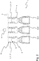
- the Fig. 2 shows a schematic cross section through an embodiment of a gripping device 1 according to the invention.
- the gripping device 1 differs according to Fig. 2 in the number of gripping means 8 or gripping tulips 8 and in the number of turns which a spring 7 connecting the respective gripping means 8 or the respective gripping tulip 8 'to the suspension 3 has.
- the number of turns of a respective spring 7 of the gripping device 1 according to Fig. 2 is compared to the number of turns of a respective spring 7 of the gripping device 1 after Fig. 1 enlarged.
- Both a respective spring 7 of the gripping device 1 according to Fig. 1 as well as a respective spring 7 of the gripping device 1 Fig. 2 has a number of turns n, for which the following applies: n ⁇ 3.
- the gripping device 1 after Fig. 2 has for each of the gripping means 8 or for each of the gripping tulips 8 ′ a linear guide 10 which comprises a flange 9 and a bushing 12.
- a respective gripping means 8 or a respective gripping tulip 8 ' is detachably attached to a respective flange 9.
- the respective flange 9, together with the respective attached gripping means 8 or together with the respective attached gripping tulip 8 ', can be linearly moved back and forth in the respective bushing 12 against the force of a respective spring 7.
- the springs 7 or the helical springs 7' are each designed as a hollow shaft 7 ′′ and each stand with the connection piece 5 and a respective gripping means 8 or a respective gripping tulip 8 'fluidically connected.
- the schematic representation of the Fig. 2 it is made clear here that a negative or positive pressure from the connection piece via the springs 7 and the respective flange 9 to the respective gripping means 8 or to the respective gripping tulip 8 'can be passed on, whereupon a respective beverage container on a respective gripping means 8 or on a respective gripping tulip 8 'is releasably fixed.
- a respective gripping means 8 or a respective gripping tulip 8 ′ is attached to a respective flange 9 formed as a component of a respective linear guide 10 and thereby releasably connected to the respective flange 9.
- the gripping means 8 or the gripping tulips 8 'together with the respective flange 9, the respective bushing 12, the respective spring 7, the suspension 3 and / or the connection piece 5 are or are produced in a three-dimensional printing process. are produced in a three-dimensional printing process.
- the Fig. 3 shows in the flowchart individual steps as they can be provided in various embodiments of a method 100 according to the invention.
- a gripping device 1 according to the embodiment Fig. 1 as well as a gripping device 1 according to the embodiment according to Fig. 2 getting produced.
- a suspension 3 As part of a first step 110, a suspension 3, several springs 7 and for each of the several springs 7 a respective linear guide 10, which respective linear guide 10 has a socket 12 and a flange 9 movable in the socket 12, are produced in a three-dimensional printing process.
- the springs 7 are manufactured in such a way that they each form a hollow shaft 7 ′′ and open into a common connection area provided by the suspension 3.
- a gripping means 8 designed to receive a respective beverage container by means of negative pressure is attached to each flange 9.
- a respective spring 7 designed as a hollow shaft 7 ′′ is fluidically connected to each gripping means 8, so that the gripping means 8 via the respective spring 7 designed as a hollow shaft 7 ′′ to receive a respective Beverage container can be acted upon with negative pressure.
- the respective spring 7 thus forms a fluidic line connection via which the respective gripping means 8 can be subjected to negative pressure or via which a negative pressure can be passed on to the respective gripping means 8.
- connection piece 5 shown in each case is attached to the suspension 3 in the area of the connection area.
- the gripping means 8 can then be subjected to negative pressure via the connection piece 5 and the springs 7, which are each designed as a hollow shaft 7 ′′, in order to receive a respective beverage container.
Landscapes
- Engineering & Computer Science (AREA)
- Mechanical Engineering (AREA)
- Robotics (AREA)
- Manipulator (AREA)
Claims (14)
- Dispositif de préhension (1) pour des récipients à boisson, comprenant- une suspension (3),- au moins un moyen de préhension (8) qui peut recevoir un récipient à boisson au moyen d'air comprimé,- au moins un ressort (7) par l'intermédiaire duquel ledit au moins un moyen de préhension (8) est relié à la suspension (3), caractérisé par le fait que
ledit au moins un ressort (7) est au moins un ressort hélicoïdal (7') et est conçu, au moins par zones, en tant que tige creuse (7"), c'est par l'intermédiaire de laquelle tige creuse (7") que ledit au moins un moyen de préhension (8) peut être alimenté en air comprimé pour recevoir le récipient à boisson. - Dispositif de préhension selon la revendication 1, dans lequel ledit au moins un ressort (7) qui est conçu au moins par zones en tant que tige creuse (7") est au moins un ressort hélicoïdal (7') qui présente trois spires ou plus.
- Dispositif de préhension selon la revendication 1 ou la revendication 2, comprenant au moins un guide linéaire (10), c'est par l'intermédiaire duquel au moins un guide linéaire (10) que ledit au moins un moyen de préhension (8) est disposé sur la suspension (3).
- Dispositif de préhension selon la revendication 3, dans lequel ledit au moins un ressort hélicoïdal (7') avec ses spires est guidé au moins par zones autour dudit au moins un guide linéaire (10).
- Dispositif de préhension selon l'une quelconque des revendications 1 à 4, dans lequel- la suspension (3) et ledit au moins un ressort (7) sont formés d'un seul tenant, ou dans lequel- la suspension (3) et ledit au moins un ressort (7) ainsi qu'au moins une douille (12) fixe qui est conçue en tant que composant dudit au moins un guide linéaire (10) sont formés d'un seul tenant.
- Dispositif de préhension selon l'une quelconque des revendications 1 à 5, dans lequel la suspension (3), ledit au moins un ressort (7) et/ou ledit au moins un guide linéaire (10) sont fabriqués selon le procédé d'impression tridimensionnelle.
- Dispositif de préhension selon a revendication 6, dans lequel- la suspension (3) et ledit au moins un ressort (7) sont fabriqués d'un seul tenant selon le procédé d'impression tridimensionnelle, ou dans lequel- la suspension (3) et ledit au moins un ressort (7) ainsi qu'au moins une douille (12) fixe qui est conçue en tant que composant dudit au moins un guide linéaire (10) sont fabriqués de préférence d'un seul tenant et selon le procédé d'impression tridimensionnelle.
- Dispositif de préhension selon l'une quelconque des revendications 1 à 7, comprenant- au moins un premier ressort (7) par l'intermédiaire duquel au moins un premier moyen de préhension (8) qui peut recevoir un récipient à boisson au moyen d'air comprimé est disposé sur la suspension (3), et lequel au moins un premier ressort (7) est conçu au moins par zones en tant que tige creuse (7"), c'est par l'intermédiaire de laquelle tige creuse (7") que ledit au moins un premier moyen de préhension (8) peut être alimenté en air comprimé pour recevoir le récipient à boisson, et comprenant- au moins un deuxième ressort (7) par l'intermédiaire duquel au moins un deuxième moyen de préhension (8) qui peut recevoir un récipient à boisson au moyen d'air comprimé est disposé sur la suspension (3), et lequel au moins un deuxième ressort (7) est conçu au moins par zones en tant que tige creuse (7"), c'est par l'intermédiaire de laquelle tige creuse (7") que ledit au moins un deuxième moyen de préhension (8) peut être alimenté en air comprimé pour recevoir le récipient à boisson, et dans lequel il est prévu que
ledit au moins un premier ressort (7) qui est conçu au moins par zones en tant que tige creuse (7"), et ledit au moins un deuxième ressort (7) qui est conçu au moins par zones en tant que tige creuse (7") débouchent dans un zone de raccordement commune. - Dispositif de préhension selon la revendication 8, dans lequel la zone de raccordement commune est formée par la suspension (3).
- Dispositif de préhension selon la revendication 9, dans lequel une pièce de raccordement (5) est fixée sur la zone de raccordement commune.
- Dispositif de préhension selon l'une quelconque des revendications 1 à 10, dans lequel ledit au moins un moyen de préhension (8) est disposé de manière détachable sur ledit au moins un ressort (7) et/ou sur ledit au moins un guide linéaire (10).
- Procédé (100) de fabrication d'un dispositif de préhension (1) qui est conçu pour recevoir des récipients à boisson et qui comprend au moins les composants suivants:- une suspension (3), au moins un moyen de préhension (8) conçu pour recevoir des récipients à boisson au moyen d'air comprimé, au moins une liaison de conduite fluidique destinée à faire passer une surpression ou une dépression audit au moins un moyen de préhension (8) conçu pour recevoir des récipients à boisson, ainsi qu'au moins un ressort (7), c'est par l'intermédiaire duquel au moins un ressort (7) que ledit au moins un moyen de préhension (8) conçu pour recevoir des récipients à boisson au moyen d'air comprimé est relié à la suspension (3), le procédé comprenant les étapes suivantes consistant à:- assembler et/ou fabriquer les composants du dispositif de préhension (1) de telle sorte qu'il en résulte la fabrication du dispositif de préhension (1), caractérisé par le fait que- ledit au moins un ressort (7) est fabriqué en tant qu'au moins un ressort hélicoïdal (7') et au moins par zones en tant que tige creuse (7"), laquelle tige (7") qui est creuse au moins par zones fournit ladite au moins une liaison de conduite fluidique destinée à faire passer une surpression ou une dépression audit au moins un moyen de préhension (8) conçu pour recevoir des récipients à boisson.
- Procédé selon la revendication 12, dans lequel,- la suspension (3) et ledit au moins un ressort (7) sont fabriqués d'un seul tenant et en matière plastique, ou dans lequel- la suspension (3) et ledit au moins un ressort (7) ainsi qu'au moins une douille (12) qui est conçue en tant que composant d'au moins un guide linéaire (10) prévu pour ledit au moins un moyen de préhension (8) sont fabriqués d'un seul tenant et en matière plastique.
- Procédé selon la revendication 12 ou la revendication 13, dans lequel- la suspension (3) et ledit au moins un ressort (7) sont fabriqués d'un seul tenant et en matière plastique selon le procédé d'impression tridimensionnelle, ou dans lequel- la suspension (3) et ledit au moins un ressort (7) ainsi qu'au moins une douille (12) qui est conçue en tant que composant d'au moins un guide linéaire (10) prévu pour ledit au moins un moyen de préhension (8) sont fabriqués d'un seul tenant et en matière plastique selon le procédé d'impression tridimensionnelle.
Applications Claiming Priority (1)
| Application Number | Priority Date | Filing Date | Title |
|---|---|---|---|
| DE102018132308.5A DE102018132308A1 (de) | 2018-12-14 | 2018-12-14 | Greifeinrichtung für Getränkebehälter und Verfahren zum Herstellen einer Greifeinrichtung |
Publications (2)
| Publication Number | Publication Date |
|---|---|
| EP3686112A1 EP3686112A1 (fr) | 2020-07-29 |
| EP3686112B1 true EP3686112B1 (fr) | 2021-11-03 |
Family
ID=68295963
Family Applications (1)
| Application Number | Title | Priority Date | Filing Date |
|---|---|---|---|
| EP19203606.9A Active EP3686112B1 (fr) | 2018-12-14 | 2019-10-16 | Dispositif de préhension pour récipients de boisson et procédé de fabrication d'un dispositif de préhension |
Country Status (3)
| Country | Link |
|---|---|
| EP (1) | EP3686112B1 (fr) |
| CN (1) | CN211619266U (fr) |
| DE (1) | DE102018132308A1 (fr) |
Families Citing this family (2)
| Publication number | Priority date | Publication date | Assignee | Title |
|---|---|---|---|---|
| DE102023125162A1 (de) * | 2023-09-18 | 2025-03-20 | Krones Aktiengesellschaft | Ausgleichselement |
| CN119460260B (zh) * | 2025-01-16 | 2025-05-30 | 山东力诺医药包装股份有限公司 | 一种玻璃制品装盒设备的多功能取瓶转送机构及转送方法 |
Family Cites Families (12)
| Publication number | Priority date | Publication date | Assignee | Title |
|---|---|---|---|---|
| US2929653A (en) * | 1954-06-28 | 1960-03-22 | Lodge & Shipley Co | Lifting cup for article transferring apparatus |
| DE1154035B (de) * | 1960-04-29 | 1963-09-05 | Holstein & Kappert Maschf | Flaschengreifer, insbesondere fuer Maschine zum Auspacken von Flaschen aus Kaesten |
| US3554594A (en) * | 1968-09-30 | 1971-01-12 | Certus Maschbau Gmbh | Pneumatically operated gripper for bottle transferring apparatus |
| DE6805541U (de) * | 1968-11-05 | 1969-07-10 | Enzinger Union Werke Ag | Maschine zum ein- und auspacken von flaschen |
| SE430881B (sv) * | 1981-02-20 | 1983-12-19 | Lars Erik Trygg | Flaskgripare |
| DE4103729C2 (de) * | 1991-02-07 | 1997-05-28 | Tyrolon Schulnig Gmbh & Co Kg | Greifvorrichtung für Flaschen o. dgl. |
| FR2878620B1 (fr) * | 2004-11-30 | 2007-02-23 | Inst Francais Du Petrole | Moteur a combustion interne, notamment moteur pour essais, avec refroidissement du piston |
| DE202005011971U1 (de) | 2005-07-27 | 2005-10-13 | Zodrow, Rudolf | Packtulpe mit nachgiebigem Gehäuse |
| CN202107099U (zh) | 2011-06-10 | 2012-01-11 | 上海星派能源科技有限公司 | 瓶料抓手 |
| DE102011051926A1 (de) | 2011-07-19 | 2013-01-24 | Krones Aktiengesellschaft | Vorrichtung zum Greifen von Artikeln |
| DE102012101554A1 (de) | 2012-02-27 | 2013-08-29 | Krones Ag | Greifvorrichtung |
| ES2768987T3 (es) * | 2013-05-24 | 2020-06-24 | Vtec Co Ltd | Ventosa con faldón separable |
-
2018
- 2018-12-14 DE DE102018132308.5A patent/DE102018132308A1/de not_active Withdrawn
-
2019
- 2019-10-16 EP EP19203606.9A patent/EP3686112B1/fr active Active
- 2019-11-04 CN CN201921886621.9U patent/CN211619266U/zh active Active
Also Published As
| Publication number | Publication date |
|---|---|
| EP3686112A1 (fr) | 2020-07-29 |
| DE102018132308A1 (de) | 2020-06-18 |
| CN211619266U (zh) | 2020-10-02 |
Similar Documents
| Publication | Publication Date | Title |
|---|---|---|
| AT508923B1 (de) | Fertigungsanlage, insbesondere für das freiformbiegen | |
| DE102011100082A1 (de) | Traygreifvorrichtung | |
| EP2666727B1 (fr) | Dispositif de levage pour une machine d'emballage | |
| DE102010021422A1 (de) | Greifvorrichtung mit elektrodynamischem Stellglied II | |
| DE102018132251B4 (de) | Werkstückbefestigungswerkzeug, Werkstücktransportvorrichtung und Robotersystem | |
| EP3119565B1 (fr) | Dispositif de montage pour le remplacement d'une pointe de préhension appartenant à un doigt de préhension pour un système robotique | |
| EP2631190B1 (fr) | Dispositif de préhension | |
| EP3431422B1 (fr) | Dispositif de préhension pour un manipulateur et procédé d'équipement d'un dispositif de préhension pour un manipulateur | |
| EP2452790A1 (fr) | Station de traitement pour une estampilleuse et procédé de sortie de feuilles d'ébauche | |
| DE102021108435A1 (de) | Greifer und Verfahren zum Umgang mit Stückgütern | |
| EP3686112A1 (fr) | Dispositif de préhension pour récipients de boisson et procédé de fabrication d'un dispositif de préhension | |
| AT503916A4 (de) | Vereinzelungsvorrichtung | |
| DE102011051926A1 (de) | Vorrichtung zum Greifen von Artikeln | |
| DE202015101448U1 (de) | Greifzangenanordnung | |
| DE202011004883U1 (de) | Packtulpe zum kopfseitigen Ergreifen von Flaschen | |
| DE102018203788A1 (de) | Vorrichtung zum Greifen zumindest eines Objekts, insbesondere eines pharmazeutischen Behältnisses | |
| DE102017211580B4 (de) | Universeller endeffektor für einen manipulator | |
| DE102015223528A1 (de) | Parallelkinematik-Roboter mit mindestens einer Entlastungseinrichtung und Verfahren zum Betreiben eines Parallelkinematik-Roboters | |
| EP3938154B1 (fr) | Dispositif de préhension | |
| DE102016014828B4 (de) | Packtulpe zum kopfseitigen Ergreifen von Flaschen | |
| DE102012022252A1 (de) | Antriebseinheit für einen Werkzeugwechsler | |
| DE10314635A1 (de) | Greifvorrichtung | |
| DE10010100A1 (de) | Greifersystem zur automatischen Entnahme von Stangen flacher Güter aus einer Transportverpackung | |
| DE102008019709A1 (de) | Roboter zum Bewegen und Positionieren von zu verpackendem Gut für eine Verpackungsmaschine | |
| DE102018131914B4 (de) | Werkzeugvorrichtung umfassend zumindest eine Gasdruckfeder |
Legal Events
| Date | Code | Title | Description |
|---|---|---|---|
| PUAI | Public reference made under article 153(3) epc to a published international application that has entered the european phase |
Free format text: ORIGINAL CODE: 0009012 |
|
| STAA | Information on the status of an ep patent application or granted ep patent |
Free format text: STATUS: THE APPLICATION HAS BEEN PUBLISHED |
|
| AK | Designated contracting states |
Kind code of ref document: A1 Designated state(s): AL AT BE BG CH CY CZ DE DK EE ES FI FR GB GR HR HU IE IS IT LI LT LU LV MC MK MT NL NO PL PT RO RS SE SI SK SM TR |
|
| AX | Request for extension of the european patent |
Extension state: BA ME |
|
| STAA | Information on the status of an ep patent application or granted ep patent |
Free format text: STATUS: REQUEST FOR EXAMINATION WAS MADE |
|
| 17P | Request for examination filed |
Effective date: 20201202 |
|
| RBV | Designated contracting states (corrected) |
Designated state(s): AL AT BE BG CH CY CZ DE DK EE ES FI FR GB GR HR HU IE IS IT LI LT LU LV MC MK MT NL NO PL PT RO RS SE SI SK SM TR |
|
| GRAP | Despatch of communication of intention to grant a patent |
Free format text: ORIGINAL CODE: EPIDOSNIGR1 |
|
| STAA | Information on the status of an ep patent application or granted ep patent |
Free format text: STATUS: GRANT OF PATENT IS INTENDED |
|
| INTG | Intention to grant announced |
Effective date: 20210518 |
|
| GRAS | Grant fee paid |
Free format text: ORIGINAL CODE: EPIDOSNIGR3 |
|
| GRAA | (expected) grant |
Free format text: ORIGINAL CODE: 0009210 |
|
| STAA | Information on the status of an ep patent application or granted ep patent |
Free format text: STATUS: THE PATENT HAS BEEN GRANTED |
|
| AK | Designated contracting states |
Kind code of ref document: B1 Designated state(s): AL AT BE BG CH CY CZ DE DK EE ES FI FR GB GR HR HU IE IS IT LI LT LU LV MC MK MT NL NO PL PT RO RS SE SI SK SM TR |
|
| REG | Reference to a national code |
Ref country code: GB Ref legal event code: FG4D Free format text: NOT ENGLISH |
|
| REG | Reference to a national code |
Ref country code: AT Ref legal event code: REF Ref document number: 1443775 Country of ref document: AT Kind code of ref document: T Effective date: 20211115 Ref country code: CH Ref legal event code: EP |
|
| REG | Reference to a national code |
Ref country code: IE Ref legal event code: FG4D Free format text: LANGUAGE OF EP DOCUMENT: GERMAN |
|
| REG | Reference to a national code |
Ref country code: DE Ref legal event code: R096 Ref document number: 502019002648 Country of ref document: DE |
|
| REG | Reference to a national code |
Ref country code: LT Ref legal event code: MG9D |
|
| REG | Reference to a national code |
Ref country code: NL Ref legal event code: MP Effective date: 20211103 |
|
| PG25 | Lapsed in a contracting state [announced via postgrant information from national office to epo] |
Ref country code: RS Free format text: LAPSE BECAUSE OF FAILURE TO SUBMIT A TRANSLATION OF THE DESCRIPTION OR TO PAY THE FEE WITHIN THE PRESCRIBED TIME-LIMIT Effective date: 20211103 Ref country code: LT Free format text: LAPSE BECAUSE OF FAILURE TO SUBMIT A TRANSLATION OF THE DESCRIPTION OR TO PAY THE FEE WITHIN THE PRESCRIBED TIME-LIMIT Effective date: 20211103 Ref country code: FI Free format text: LAPSE BECAUSE OF FAILURE TO SUBMIT A TRANSLATION OF THE DESCRIPTION OR TO PAY THE FEE WITHIN THE PRESCRIBED TIME-LIMIT Effective date: 20211103 Ref country code: BG Free format text: LAPSE BECAUSE OF FAILURE TO SUBMIT A TRANSLATION OF THE DESCRIPTION OR TO PAY THE FEE WITHIN THE PRESCRIBED TIME-LIMIT Effective date: 20220203 |
|
| PG25 | Lapsed in a contracting state [announced via postgrant information from national office to epo] |
Ref country code: IS Free format text: LAPSE BECAUSE OF FAILURE TO SUBMIT A TRANSLATION OF THE DESCRIPTION OR TO PAY THE FEE WITHIN THE PRESCRIBED TIME-LIMIT Effective date: 20220303 Ref country code: SE Free format text: LAPSE BECAUSE OF FAILURE TO SUBMIT A TRANSLATION OF THE DESCRIPTION OR TO PAY THE FEE WITHIN THE PRESCRIBED TIME-LIMIT Effective date: 20211103 Ref country code: PT Free format text: LAPSE BECAUSE OF FAILURE TO SUBMIT A TRANSLATION OF THE DESCRIPTION OR TO PAY THE FEE WITHIN THE PRESCRIBED TIME-LIMIT Effective date: 20220303 Ref country code: PL Free format text: LAPSE BECAUSE OF FAILURE TO SUBMIT A TRANSLATION OF THE DESCRIPTION OR TO PAY THE FEE WITHIN THE PRESCRIBED TIME-LIMIT Effective date: 20211103 Ref country code: NO Free format text: LAPSE BECAUSE OF FAILURE TO SUBMIT A TRANSLATION OF THE DESCRIPTION OR TO PAY THE FEE WITHIN THE PRESCRIBED TIME-LIMIT Effective date: 20220203 Ref country code: NL Free format text: LAPSE BECAUSE OF FAILURE TO SUBMIT A TRANSLATION OF THE DESCRIPTION OR TO PAY THE FEE WITHIN THE PRESCRIBED TIME-LIMIT Effective date: 20211103 Ref country code: LV Free format text: LAPSE BECAUSE OF FAILURE TO SUBMIT A TRANSLATION OF THE DESCRIPTION OR TO PAY THE FEE WITHIN THE PRESCRIBED TIME-LIMIT Effective date: 20211103 Ref country code: HR Free format text: LAPSE BECAUSE OF FAILURE TO SUBMIT A TRANSLATION OF THE DESCRIPTION OR TO PAY THE FEE WITHIN THE PRESCRIBED TIME-LIMIT Effective date: 20211103 Ref country code: GR Free format text: LAPSE BECAUSE OF FAILURE TO SUBMIT A TRANSLATION OF THE DESCRIPTION OR TO PAY THE FEE WITHIN THE PRESCRIBED TIME-LIMIT Effective date: 20220204 Ref country code: ES Free format text: LAPSE BECAUSE OF FAILURE TO SUBMIT A TRANSLATION OF THE DESCRIPTION OR TO PAY THE FEE WITHIN THE PRESCRIBED TIME-LIMIT Effective date: 20211103 |
|
| PG25 | Lapsed in a contracting state [announced via postgrant information from national office to epo] |
Ref country code: SM Free format text: LAPSE BECAUSE OF FAILURE TO SUBMIT A TRANSLATION OF THE DESCRIPTION OR TO PAY THE FEE WITHIN THE PRESCRIBED TIME-LIMIT Effective date: 20211103 Ref country code: SK Free format text: LAPSE BECAUSE OF FAILURE TO SUBMIT A TRANSLATION OF THE DESCRIPTION OR TO PAY THE FEE WITHIN THE PRESCRIBED TIME-LIMIT Effective date: 20211103 Ref country code: RO Free format text: LAPSE BECAUSE OF FAILURE TO SUBMIT A TRANSLATION OF THE DESCRIPTION OR TO PAY THE FEE WITHIN THE PRESCRIBED TIME-LIMIT Effective date: 20211103 Ref country code: EE Free format text: LAPSE BECAUSE OF FAILURE TO SUBMIT A TRANSLATION OF THE DESCRIPTION OR TO PAY THE FEE WITHIN THE PRESCRIBED TIME-LIMIT Effective date: 20211103 Ref country code: DK Free format text: LAPSE BECAUSE OF FAILURE TO SUBMIT A TRANSLATION OF THE DESCRIPTION OR TO PAY THE FEE WITHIN THE PRESCRIBED TIME-LIMIT Effective date: 20211103 Ref country code: CZ Free format text: LAPSE BECAUSE OF FAILURE TO SUBMIT A TRANSLATION OF THE DESCRIPTION OR TO PAY THE FEE WITHIN THE PRESCRIBED TIME-LIMIT Effective date: 20211103 |
|
| REG | Reference to a national code |
Ref country code: DE Ref legal event code: R097 Ref document number: 502019002648 Country of ref document: DE |
|
| PLBE | No opposition filed within time limit |
Free format text: ORIGINAL CODE: 0009261 |
|
| STAA | Information on the status of an ep patent application or granted ep patent |
Free format text: STATUS: NO OPPOSITION FILED WITHIN TIME LIMIT |
|
| 26N | No opposition filed |
Effective date: 20220804 |
|
| PG25 | Lapsed in a contracting state [announced via postgrant information from national office to epo] |
Ref country code: AL Free format text: LAPSE BECAUSE OF FAILURE TO SUBMIT A TRANSLATION OF THE DESCRIPTION OR TO PAY THE FEE WITHIN THE PRESCRIBED TIME-LIMIT Effective date: 20211103 |
|
| PG25 | Lapsed in a contracting state [announced via postgrant information from national office to epo] |
Ref country code: SI Free format text: LAPSE BECAUSE OF FAILURE TO SUBMIT A TRANSLATION OF THE DESCRIPTION OR TO PAY THE FEE WITHIN THE PRESCRIBED TIME-LIMIT Effective date: 20211103 |
|
| PG25 | Lapsed in a contracting state [announced via postgrant information from national office to epo] |
Ref country code: MC Free format text: LAPSE BECAUSE OF FAILURE TO SUBMIT A TRANSLATION OF THE DESCRIPTION OR TO PAY THE FEE WITHIN THE PRESCRIBED TIME-LIMIT Effective date: 20211103 |
|
| REG | Reference to a national code |
Ref country code: CH Ref legal event code: PL |
|
| REG | Reference to a national code |
Ref country code: BE Ref legal event code: MM Effective date: 20221031 |
|
| P01 | Opt-out of the competence of the unified patent court (upc) registered |
Effective date: 20230523 |
|
| PG25 | Lapsed in a contracting state [announced via postgrant information from national office to epo] |
Ref country code: LU Free format text: LAPSE BECAUSE OF NON-PAYMENT OF DUE FEES Effective date: 20221016 |
|
| PG25 | Lapsed in a contracting state [announced via postgrant information from national office to epo] |
Ref country code: LI Free format text: LAPSE BECAUSE OF NON-PAYMENT OF DUE FEES Effective date: 20221031 Ref country code: CH Free format text: LAPSE BECAUSE OF NON-PAYMENT OF DUE FEES Effective date: 20221031 |
|
| PG25 | Lapsed in a contracting state [announced via postgrant information from national office to epo] |
Ref country code: BE Free format text: LAPSE BECAUSE OF NON-PAYMENT OF DUE FEES Effective date: 20221031 |
|
| PG25 | Lapsed in a contracting state [announced via postgrant information from national office to epo] |
Ref country code: IE Free format text: LAPSE BECAUSE OF NON-PAYMENT OF DUE FEES Effective date: 20221016 |
|
| PG25 | Lapsed in a contracting state [announced via postgrant information from national office to epo] |
Ref country code: HU Free format text: LAPSE BECAUSE OF FAILURE TO SUBMIT A TRANSLATION OF THE DESCRIPTION OR TO PAY THE FEE WITHIN THE PRESCRIBED TIME-LIMIT; INVALID AB INITIO Effective date: 20191016 |
|
| PG25 | Lapsed in a contracting state [announced via postgrant information from national office to epo] |
Ref country code: CY Free format text: LAPSE BECAUSE OF FAILURE TO SUBMIT A TRANSLATION OF THE DESCRIPTION OR TO PAY THE FEE WITHIN THE PRESCRIBED TIME-LIMIT Effective date: 20211103 |
|
| PG25 | Lapsed in a contracting state [announced via postgrant information from national office to epo] |
Ref country code: MK Free format text: LAPSE BECAUSE OF FAILURE TO SUBMIT A TRANSLATION OF THE DESCRIPTION OR TO PAY THE FEE WITHIN THE PRESCRIBED TIME-LIMIT Effective date: 20211103 |
|
| GBPC | Gb: european patent ceased through non-payment of renewal fee |
Effective date: 20231016 |
|
| PG25 | Lapsed in a contracting state [announced via postgrant information from national office to epo] |
Ref country code: TR Free format text: LAPSE BECAUSE OF FAILURE TO SUBMIT A TRANSLATION OF THE DESCRIPTION OR TO PAY THE FEE WITHIN THE PRESCRIBED TIME-LIMIT Effective date: 20211103 |
|
| PG25 | Lapsed in a contracting state [announced via postgrant information from national office to epo] |
Ref country code: GB Free format text: LAPSE BECAUSE OF NON-PAYMENT OF DUE FEES Effective date: 20231016 |
|
| PG25 | Lapsed in a contracting state [announced via postgrant information from national office to epo] |
Ref country code: GB Free format text: LAPSE BECAUSE OF NON-PAYMENT OF DUE FEES Effective date: 20231016 |
|
| PG25 | Lapsed in a contracting state [announced via postgrant information from national office to epo] |
Ref country code: MT Free format text: LAPSE BECAUSE OF FAILURE TO SUBMIT A TRANSLATION OF THE DESCRIPTION OR TO PAY THE FEE WITHIN THE PRESCRIBED TIME-LIMIT Effective date: 20211103 |
|
| REG | Reference to a national code |
Ref country code: DE Ref legal event code: R082 Ref document number: 502019002648 Country of ref document: DE Representative=s name: BENNINGER, JOHANNES, DIPL.-ING., DE |
|
| PGFP | Annual fee paid to national office [announced via postgrant information from national office to epo] |
Ref country code: IT Payment date: 20250922 Year of fee payment: 7 |
|
| PGFP | Annual fee paid to national office [announced via postgrant information from national office to epo] |
Ref country code: FR Payment date: 20250908 Year of fee payment: 7 |
|
| REG | Reference to a national code |
Ref country code: AT Ref legal event code: MM01 Ref document number: 1443775 Country of ref document: AT Kind code of ref document: T Effective date: 20241016 |
|
| PGFP | Annual fee paid to national office [announced via postgrant information from national office to epo] |
Ref country code: DE Payment date: 20250902 Year of fee payment: 7 |
|
| PG25 | Lapsed in a contracting state [announced via postgrant information from national office to epo] |
Ref country code: AT Free format text: LAPSE BECAUSE OF NON-PAYMENT OF DUE FEES Effective date: 20241016 |
|
| PGFP | Annual fee paid to national office [announced via postgrant information from national office to epo] |
Ref country code: AT Payment date: 20260410 Year of fee payment: 5 |