EP3686112B1 - Gripping device for beverage containers and method for producing a gripping device - Google Patents
Gripping device for beverage containers and method for producing a gripping device Download PDFInfo
- Publication number
- EP3686112B1 EP3686112B1 EP19203606.9A EP19203606A EP3686112B1 EP 3686112 B1 EP3686112 B1 EP 3686112B1 EP 19203606 A EP19203606 A EP 19203606A EP 3686112 B1 EP3686112 B1 EP 3686112B1
- Authority
- EP
- European Patent Office
- Prior art keywords
- spring
- gripping
- suspension
- designed
- gripping device
- Prior art date
- Legal status (The legal status is an assumption and is not a legal conclusion. Google has not performed a legal analysis and makes no representation as to the accuracy of the status listed.)
- Active
Links
Images


Classifications
-
- B—PERFORMING OPERATIONS; TRANSPORTING
- B65—CONVEYING; PACKING; STORING; HANDLING THIN OR FILAMENTARY MATERIAL
- B65B—MACHINES, APPARATUS OR DEVICES FOR, OR METHODS OF, PACKAGING ARTICLES OR MATERIALS; UNPACKING
- B65B21/00—Packaging or unpacking of bottles
- B65B21/02—Packaging or unpacking of bottles in or from preformed containers, e.g. crates
- B65B21/14—Introducing or removing groups of bottles, for filling or emptying containers in one operation
- B65B21/18—Introducing or removing groups of bottles, for filling or emptying containers in one operation using grippers engaging bottles, e.g. bottle necks
- B65B21/186—Inflatable grippers
-
- B—PERFORMING OPERATIONS; TRANSPORTING
- B25—HAND TOOLS; PORTABLE POWER-DRIVEN TOOLS; MANIPULATORS
- B25J—MANIPULATORS; CHAMBERS PROVIDED WITH MANIPULATION DEVICES
- B25J15/00—Gripping heads and other end effectors
- B25J15/0023—Gripper surfaces directly activated by a fluid
-
- B—PERFORMING OPERATIONS; TRANSPORTING
- B25—HAND TOOLS; PORTABLE POWER-DRIVEN TOOLS; MANIPULATORS
- B25J—MANIPULATORS; CHAMBERS PROVIDED WITH MANIPULATION DEVICES
- B25J15/00—Gripping heads and other end effectors
- B25J15/0052—Gripping heads and other end effectors multiple gripper units or multiple end effectors
-
- B—PERFORMING OPERATIONS; TRANSPORTING
- B25—HAND TOOLS; PORTABLE POWER-DRIVEN TOOLS; MANIPULATORS
- B25J—MANIPULATORS; CHAMBERS PROVIDED WITH MANIPULATION DEVICES
- B25J19/00—Accessories fitted to manipulators, e.g. for monitoring, for viewing; Safety devices combined with or specially adapted for use in connection with manipulators
- B25J19/0025—Means for supplying energy to the end effector
- B25J19/0029—Means for supplying energy to the end effector arranged within the different robot elements
-
- B—PERFORMING OPERATIONS; TRANSPORTING
- B65—CONVEYING; PACKING; STORING; HANDLING THIN OR FILAMENTARY MATERIAL
- B65B—MACHINES, APPARATUS OR DEVICES FOR, OR METHODS OF, PACKAGING ARTICLES OR MATERIALS; UNPACKING
- B65B21/00—Packaging or unpacking of bottles
- B65B21/02—Packaging or unpacking of bottles in or from preformed containers, e.g. crates
- B65B21/08—Introducing or removing single bottles, or groups of bottles, e.g. for progressive filling or emptying of containers
- B65B21/12—Introducing or removing single bottles, or groups of bottles, e.g. for progressive filling or emptying of containers using grippers engaging bottles, e.g. bottle necks
-
- B—PERFORMING OPERATIONS; TRANSPORTING
- B65—CONVEYING; PACKING; STORING; HANDLING THIN OR FILAMENTARY MATERIAL
- B65B—MACHINES, APPARATUS OR DEVICES FOR, OR METHODS OF, PACKAGING ARTICLES OR MATERIALS; UNPACKING
- B65B35/00—Supplying, feeding, arranging or orientating articles to be packaged
- B65B35/10—Feeding, e.g. conveying, single articles
- B65B35/16—Feeding, e.g. conveying, single articles by grippers
- B65B35/18—Feeding, e.g. conveying, single articles by grippers by suction-operated grippers
-
- B—PERFORMING OPERATIONS; TRANSPORTING
- B65—CONVEYING; PACKING; STORING; HANDLING THIN OR FILAMENTARY MATERIAL
- B65G—TRANSPORT OR STORAGE DEVICES, e.g. CONVEYORS FOR LOADING OR TIPPING, SHOP CONVEYOR SYSTEMS OR PNEUMATIC TUBE CONVEYORS
- B65G47/00—Article or material-handling devices associated with conveyors; Methods employing such devices
- B65G47/74—Feeding, transfer, or discharging devices of particular kinds or types
- B65G47/90—Devices for picking-up and depositing articles or materials
- B65G47/908—Devices for picking-up and depositing articles or materials with inflatable picking-up means
Definitions
- the present invention relates to a gripping device for beverage containers and a method for producing a gripping device for beverage containers.
- packing or gripping tulips are used to handle articles such as containers, in particular bottles.
- the handling can, for example, provide for articles, such as containers, in particular bottles, to be moved from one location to another or to be placed in an outer packaging, for example a cardboard box or a beverage crate.
- An article or a beverage container which can be received by means of gripping tulips known from the prior art has a lateral lateral surface which normally tapers in the area of an upper neck section.
- Such a beverage container or such a beverage bottle can be closed by a lid at an overhead end area.
- a gripping tulip In order to move articles such as beverage bottles by means of gripping tulips or to insert them into outer packaging, a gripping tulip is lowered onto an article when it is gripped on the head side, until the gripping means at least partially encompasses an upper part of the outer surface of the article provided as a contact section .
- the gripping tulip By actuating or activating gripping elements of the gripping tulip, the article is then fixed to the gripping tulip in question, but can, if necessary, also be detached from the gripping tulip. If the gripping tulip is raised, the article attached to the gripping tulip is also raised together with the gripping tulip.
- a gripping tulip for the head-side gripping of bottles that can be closed in particular by corks, crown caps, screw or clip closures.
- This known gripping tulip has in a pot-shaped housing a sleeve-shaped, elastically deformable insert supported with its front end on the pot rim of the housing and an actuating piston acting on the insert at its rear end with an axial compressive force.
- the housing of the gripping tulip is formed in the front area by a radially outwardly elastically deformable wall.
- US 2016/0096278 A1 discloses a suction instrument with a connecting means, a rubber base and a bellows, which bellows has a projection and is arranged over this projection in a recess of the connecting means.
- the suction device can be used to accept items using negative pressure.
- the gripping instrument comprises a sleeve into which a bottle holder is dipped for receiving.
- a column that is flexible is connected to the sleeve.
- the column is further arranged on a frame.
- the CN 202 107 099 U discloses a gripping tulip, the gripping means of which comprise two oppositely arranged bilateral levers. Each of the two bilateral levers can be pivoted about one of two parallel horizontal axes. A lower lever arm of each bilateral lever, which is provided for gripping an article, is designed as a gripping jaw. An upper lever arm of each bilateral lever, which is provided for the action of a wedge movable up and down by means of an actuating device, is connected to a spring. By inserting a wedge that can be moved up and down via the actuating device between the upper parts of the two bilateral levers, the gripping jaws move towards each other like pliers in order to grip an article on the head side and finally to reach the holding position. Retraction of the wedge causes the gripping jaws to open and thus a gripped article to be released.
- a gripping tulip which also uses a wedge effect to reach a holding position of its gripping means designed as gripping jaws. Since the wedge interacts with a subsequent section, which can be switched between two mechanically stable states, holding positions free of actuation force are made possible in each case.
- this gripping tulip can assume a holding position that is to be maintained without force.
- the DE 10 2012 101 554 A1 discloses a further gripping tulip, the gripping means of which comprise at least three gripping tongues encompassing the contact section of an article at approximately the same height on all sides.
- Each of the gripping tongues is suspended pivotably or elastically on a holding frame of the gripping tulip and is supported there. At their end faces facing away from the holding frame, the gripping tongues each point inwardly toward one another towards the contact section.
- the gripping tongues are raised by lowering the gripping tulip on the head side parallel to the height of an article extending normally to the base surface over a neck section of the article against elastic restoring forces pushed apart obliquely upwards and each brought into an angular position to the holding frame, the end faces of the gripping tongues being supported in a form-fitting and / or force-fitting manner against the contact section of the article.
- a primary object of the invention can therefore be seen in providing a gripping device and a corresponding method for producing a gripping device, by means of which the problems mentioned can be avoided or at least reduced.
- the invention relates to a gripping device for articles such as, in particular, beverage containers.
- the beverage containers which can be received by means of the gripping device can in particular be glass bottles.
- the beverage containers which can be received by means of the gripping device can, however, in particular also be PET bottles.
- Mixed forms, i.e. bottles made from a mix of materials, can also count as articles or beverage containers within the meaning of the definition of the present invention.
- the gripping device comprises a suspension and at least one gripping means which can receive a beverage container by means of compressed air or by means of overpressure or underpressure.
- a pressure medium such as in particular compressed air is meant which is used to generate a suction effect or a gripping effect in the Gripping device is used. Since the gripping device according to the invention can work with both negative and positive pressure, and since a compressible and inexpensively available gas such as compressed air is used as the pressure medium, compressed air is often used in general terms in the further context of the description and the claims.
- the suspension of the gripping device can be designed as a plate which, for example, has two opposite and possibly square-shaped broad side surfaces. If the gripping device comprises several gripping means or at least one first gripping means as well as at least one second gripping means, the suspension can be positioned above the at least one first gripping means and the at least one second gripping means, with edge regions of the suspension the at least one first gripping means and the at least one second Gripping means protrude laterally, or wherein edge regions of the suspension extend laterally beyond the at least one first gripping means and the at least one second gripping means.
- the gripping device further comprises at least one spring, via which the at least one gripping means is connected to the suspension.
- each spring of the gripping device is assigned its own flange, for example, have proven successful.
- the respective flange of its own can optionally be arranged on a lower end region of the spring. It is conceivable here that a gripping means provided for receiving a beverage container with compressed air (underpressure or overpressure) can be releasably attached to a respective flange of its own.
- the respective flange and the respective gripping means interact via latching and / or snap and / or clamping connections in order to releasably attach the respective gripping means to the respective flange.
- embodiments have proven to be useful in which a respective gripping means can be attached to the respective flange.
- the at least one gripping means can be designed in such a way that the at least one gripping means is controlled via compressed air (negative pressure or overpressure) and, as a result, fixes or receives a respective beverage container mechanically and possibly by means of a gripping jaw and / or by means of a lever.
- compressed air negative pressure or overpressure
- embodiments have proven to be useful in which a negative pressure or positive pressure is transmitted to the at least one gripping means, the respective beverage container being sucked in by means of the negative pressure or positive pressure transferred to the respective gripping means and held at the respective gripping means.
- the at least one spring is designed, at least in some areas, as a hollow shaft or as a curved hollow tube. It is conceivable that the at least one gripping means for receiving the beverage container can be acted upon with compressed air (underpressure or overpressure) via the hollow shaft or via the curved hollow tube. As an alternative or in addition to this, it is also conceivable that electrical line connections of the gripping device, hydraulic components and / or sensor components, which are designed as part of the gripping device, are introduced into the hollow shaft or into the curved hollow tube of the at least one spring. Due to the design as a hollow shaft or as a curved hollow tube and the pressurization of the beverage container or the introduction of further components of the gripping device into the hollow shaft or into the curved hollow tube, the gripping device has a clear and compact structure.
- the at least one spring is designed completely or continuously along its course as a hollow shaft or as a hollow tube, via which hollow shaft the at least one gripping means for receiving the beverage container can be acted upon with compressed air (negative pressure or positive pressure).
- the at least one gripping means is controlled differently than by compressed air, for example by an electric motor, electromagnetic or by means of a piezo element or the like the provides at least one gripping means.
- the spring can optionally be designed as a hollow shaft or as a solid shaft. Since a compressed air supply for the spring is not required in this variant, so that the spring does not have to serve as a line for compressed air, the force or energy transmission for the control of the gripping means can take place in other ways, for example by means of electrical lines that are wound around the spring or molded into this are. Manufacturing processes in which foil-like electrical lines are routed to the outer surfaces of the spring and firmly attached there are also conceivable.
- each spring of the gripping device is assigned its own flange.
- the respective spring can open into the respective flange or into the respective own flange, so that a negative pressure or overpressure can be transmitted from the respective spring to the respective flange or to the respective own flange. If a respective gripping means is detachably attached to the respective flange, the respective negative pressure or overpressure can then be transmitted from the respective flange to the respective gripping means attached to the flange.
- the at least one spring which is at least partially designed as a hollow shaft or as a hollow tube, is at least one helical spring. It can also be that the at least one spring, which is at least partially designed as a hollow shaft or as a hollow tube, is at least one helical spring with at least three turns. This can possibly also be expressed in that the helical spring has a respective number of turns n, for which the following applies: n ⁇ 3.
- the at least one spring, at least partially designed as a hollow shaft, or the at least one helical spring can be positioned between the suspension and the respective gripping means.
- the at least one spring, at least partially designed as a hollow shaft, or the at least one helical spring is positioned or arranged between the suspension and a respective flange of its own that has already been described above.
- the spring can optionally be designed as a hollow shaft or as a hollow tube in certain areas.
- the spring can be a helical spring, for example. Variants are also conceivable in which the spring is formed by a solid and non-hollow material, since no compressed air has to be guided in the cavity. It can also be the case that the at least one spring, which is either solid or at least regionally designed as a hollow shaft or as a hollow tube, is at least one helical spring with at least three turns. This can possibly also be expressed in that the helical spring has a respective number of turns n, for which the following applies: n ⁇ 3.
- the at least one spring configured as a solid shaft or possibly at least partially as a hollow shaft or the at least one helical spring can be positioned between the suspension and the respective gripping means.
- the at least one solidly designed or at least partially designed as a hollow shaft spring or the at least one helical spring is positioned or arranged between the suspension and a respective previously described separate flange.
- the gripping device can comprise at least one linear guide, via which at least one linear guide the at least one gripping means is arranged on the suspension.
- each gripping means of the gripping device can be assigned its own linear guide, via which the respective gripping means is fixed to the suspension.
- a respective linear guide can, for example, comprise a bushing.
- the respective socket and the suspension can optionally be formed in one piece.
- the respective flange already described above and a respective bushing can jointly form a respective linear guide. It is conceivable here that the respective flange can be moved to and fro in a linear direction relative to the respective socket.
- the respective flange can be arranged at least in some areas within the respective socket.
- the at least one spring, at least partially designed as a hollow shaft is at least one helical spring and that the at least one helical spring is guided with its coils at least in sections around the at least one linear guide.
- the at least one spring, at least partially designed as a hollow shaft is at least one helical spring and that the at least one helical spring is guided with its windings at least in sections around at least one bushing designed as a component of the at least one linear guide and previously mentioned.
- the at least one spring, at least partially designed as a solid shaft is at least one helical spring and that the windings of the at least one helical spring are at least partially guided around the at least one linear guide.
- the at least one spring, at least partially designed as a solid shaft is at least one helical spring and that the at least one helical spring with its coils is at least partially guided around at least one as a component of the at least one linear guide and previously mentioned bushing.
- suspension and the at least one spring are formed in one piece or that the suspension and the at least one spring and at least one bush or fixed bush formed as a component of the at least one linear guide are formed in one piece.
- the suspension, the at least one spring and / or the at least one linear guide are produced using a three-dimensional printing process, i.e. usually using a laser sintering process. It is also conceivable that the gripping device with all its components is manufactured using a three-dimensional printing process, i.e. using a laser sintering process or a similar manufacturing process.
- the gripping device can comprise at least one first spring.
- At least one first gripping means which can receive a beverage container via compressed air (negative pressure or positive pressure), can be arranged on the suspension via the at least one first spring.
- the at least one first spring can at least partially be designed as a hollow shaft, via which hollow shaft the at least one first gripping means for receiving the beverage container can be acted upon with compressed air (negative pressure or positive pressure).
- the gripping device can comprise at least one second spring, via which at least one second gripping means, which can receive a beverage container via compressed air (negative pressure or overpressure), is arranged on the suspension, which at least one second spring is at least partially designed as a hollow shaft which hollow shaft the at least one second gripping means for receiving the beverage container can be acted upon with compressed air (negative pressure or positive pressure).
- the common connection area can be formed by the suspension.
- a connection piece can be fixed or arranged on the suspension, which can transmit a negative pressure or overpressure to the connection area formed by the suspension.
- the gripping device can comprise at least one first spring.
- at least one first gripping means Via the at least one first spring, at least one first gripping means, which can receive a beverage container via suitable actuators (e.g. mechanical, electromagnetic, piezoelectric, electromotive, etc.), can be arranged on the suspension.
- suitable actuators e.g. mechanical, electromagnetic, piezoelectric, electromotive, etc.
- the at least one first spring can at least partially be designed as a solid and / or line-leading shaft, via which shaft the at least one first gripping means for receiving the beverage container can be supplied with energy and / or with suitable control signals.
- the gripping device can comprise at least one second spring, via which at least one second gripping means, which can grasp, pick up and / or receive a beverage container via suitable mechanics or actuators (e.g. mechanical, electromagnetic, piezoelectric, electromotive, etc.) Suspension is arranged, which at least one second spring is at least partially designed as a solid and / or line-leading shaft, via which solid and / or line-leading shaft the at least one second gripping means for receiving the beverage container can be supplied with energy and / or with suitable control signals.
- suitable mechanics or actuators e.g. mechanical, electromagnetic, piezoelectric, electromotive, etc.
- the at least one first spring, at least partially designed as a solid and / or line-guiding shaft, and the at least one second spring, at least partially designed as a solid and / or line-guiding shaft, into a common connection area flow out.
- the common connection area can be formed by the suspension.
- a connection piece, which can transmit electrical or other signals to the connection area formed by the suspension, can be fixed or arranged on the suspension.
- the gripping device has at least one electrical line connection. It may be that the at least one electrical line connection is at least partially received in the at least one spring, which at least one spring is at least partially designed as a hollow shaft, via which hollow shaft the at least one gripping means for receiving the beverage container can be acted upon with compressed air . So it is conceivable that electrical lines, cable connections, electrical connections, etc. for electrical power supply, control of the gripping means etc. are at least partially received in the at least one spring designed as a hollow shaft.
- the gripping device has at least one hydraulic line connection.
- the at least one hydraulic line connection is at least partially received in the at least one spring, which at least one spring is at least partially designed as a hollow shaft, via which hollow shaft the at least one gripping means for receiving the beverage container can be acted upon with compressed air .
- the at least one hydraulic line connection and / or at least one hydraulic component such as cylinder, pressure vessel etc. for actuating the gripping means etc. can be received at least in sections in the at least one spring designed as a hollow shaft.
- the gripping device has at least one sensory component. It can be that the at least one sensory component is at least partially received in the at least one spring, which at least one spring is at least partially designed as a hollow shaft, over which hollow shaft the at least one gripping means for receiving the beverage container with a sensory component is formed can be. It is conceivable that sensors or other sensory components for signal-emitting functions etc. are received at least in sections in the at least one spring designed as a hollow shaft.
- connection piece is designed as a one-piece component of the suspension and, if necessary, is produced together with the suspension using a three-dimensional printing process.
- the at least one gripping means can be detachably arranged on the at least one spring and / or on the at least one linear guide. It can also be the case that the at least one gripping means, the suspension and / or the at least one spring are designed in one piece and, if necessary, are produced using a three-dimensional printing process.
- the invention also relates to a method for producing a gripping device designed to receive beverage containers.
- a gripping device designed to receive beverage containers.
- Features which have already been described above for various embodiments of the gripping device can also be used for embodiments described below of the procedure and are not mentioned more than once.
- features described below, which relate to various embodiments of the method can be provided in the previously described embodiments of a gripping device.
- One step of the method provides for the components of the gripping device to be assembled and / or manufactured so that the gripping device is produced as a result.
- the at least one spring is manufactured at least partially as a hollow shaft or as a hollow tube, ie as a coiled or regularly curved hollow tube, which at least partially hollow shaft of the at least one spring is the at least one fluidic line connection for transferring a negative or positive pressure to the provides at least one gripping means designed to receive beverage containers.
- One step of the alternative method provides for the components of the gripping device to be assembled and / or manufactured so that the gripping device is produced as a result.
- the at least one spring is manufactured at least partially as a solid and / or line-guiding shaft, ie as a coiled or regularly curved shaft, which at least partially solid shaft of the at least one spring is the at least one control and / or line connection for transmission of control signals to which provides at least one gripping means designed to receive beverage containers.
- all components of the gripping device are manufactured using a three-dimensional printing process. It may be that the gripping device with all its components is manufactured using the three-dimensional printing process, so that the gripping device is manufactured immediately after the three-dimensional printing process has been completed. In such embodiments, it is not necessary for individual components of the gripping device to be assembled after the three-dimensional printing process has been completed. In further embodiments it can be the case that several components of the gripping device are produced in the three-dimensional printing process and are combined with further components of the gripping device after the completion of the three-dimensional printing process.
- suspension and the at least one spring are made in one piece and made of plastic. It can also be that the suspension and the at least one spring as well as at least one bushing, which is designed as a component of at least one linear guide provided for the at least one gripping means, are manufactured in one piece and from plastic. It is also conceivable that the suspension and the at least one spring, as well as at least one linear guide provided for the at least one gripping means, are manufactured entirely from plastic and possibly using a three-dimensional printing process.
- Embodiments in which the suspension and the at least one spring are made in one piece and made of plastic in three dimensions have also proven successful Printing process are manufactured.
- Embodiments have also proven themselves in which the suspension and the at least one spring as well as at least one bushing, which is designed as a component of at least one linear guide provided for the at least one gripping means, are made in one piece and made of plastic in a three-dimensional printing process.
- the at least one spring can be manufactured as a helical spring with three or more turns. In other words, the at least one spring can be manufactured as a helical spring with a number of turns n, where: n 3.
- the Fig. 1 shows a schematic perspective view of an embodiment of a gripping device 1 according to the invention.
- the gripping device 1 from the embodiment according to FIG Fig. 1 is provided for receiving beverage containers, which can be made up of glass bottles or PET bottles, for example.
- the gripping device 1 has a suspension 3, from which suspension 3 a connection piece 5 protrudes in an upward direction.
- a device for generating a pneumatic negative pressure can be coupled to the connection piece 5.
- the gripping device 1 further comprises several gripping means 8, each of which is designed as a gripping tulip 8 'and can each receive a beverage container or a glass bottle or PET bottle by means of compressed air (negative or positive pressure).
- the underpressure or overpressure is transmitted via the connection piece 5 to the gripping means 8 or to the gripping tulips 8 '.
- the gripping device 1 In order to receive several beverage containers or several glass bottles or PET bottles, the gripping device 1 is first placed on the respective several beverage containers in the direction from above, the several beverage containers immersing in sections into the gripping means 8 designed as gripping tulips 8 '.
- the gripping means 8 or gripping tulips 8 ' are each resiliently mounted.
- the reference number 7 refers in Fig. 1 on a respective spring, via which a respective gripping means 8 or a respective gripping tulip 8 ' with the suspension 3 is in connection.
- a separate spring 7 is thus provided, which fixes the respective gripping means 8 or the respective gripping tulip 8' to the suspension 3.
- the springs 7 are each designed as a helical spring 7 '.
- the gripping means 8 or gripping tulips 8 ' are controlled with compressed air (negative or positive pressure), for which purpose fluidic line connections are required which apply the respective negative or positive pressure (ie the medium “compressed air") to the respective gripping means 8 or transferred to the respective gripping tulip 8 '.
- compressed air negative or positive pressure
- these fluidic line connections are unfavorably located on the outside or are designed as separate components of the respective gripping device. If such a gripping device is manufactured, the fluidic line connections must each be fixed to the gripping means 8 or gripping tulips 8 ', which is associated with a high level of effort in the manufacture or assembly of the individual components of a gripping device. If such gripping devices known from the prior art are used to receive beverage containers and move them towards a destination, it can happen that the external pneumatic line connections inadvertently get caught in an obstacle along a path of the gripping device, which may damage the gripping device can be.
- the springs 7 and the helical springs 7 ' are each designed as a hollow shaft 7 ", which hollow shaft 7" can transmit a negative or positive pressure to the gripping means 8 or to the gripping tulips 8 ".
- All springs each designed as a hollow shaft 7" 7 open into a common connection area, to which common connection area the connection piece 5 is coupled.
- the common connection area is formed by the suspension 3 or provided by the suspension 3.
- a vacuum or overpressure can therefore be transmitted to the gripping means 8 or the gripping tulips 8 'via the springs 7, which are each designed as a hollow shaft 7 ′′, in order to receive beverage containers or the gripping tulips 8 'on the suspension 3 as well as the transfer or passing on an underpressure or overpressure from the connection piece 5 to the gripping means 8 or gripping tulips 8 '.
- the suspension 3 and all springs 7 are made in one piece from plastic using a three-dimensional printing process, which means in particular a laser sintering process or a similar manufacturing process.
- the gripping device 1 can therefore be produced easily and with little expenditure of time.
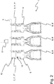
- the Fig. 2 shows a schematic cross section through an embodiment of a gripping device 1 according to the invention.
- the gripping device 1 differs according to Fig. 2 in the number of gripping means 8 or gripping tulips 8 and in the number of turns which a spring 7 connecting the respective gripping means 8 or the respective gripping tulip 8 'to the suspension 3 has.
- the number of turns of a respective spring 7 of the gripping device 1 according to Fig. 2 is compared to the number of turns of a respective spring 7 of the gripping device 1 after Fig. 1 enlarged.
- Both a respective spring 7 of the gripping device 1 according to Fig. 1 as well as a respective spring 7 of the gripping device 1 Fig. 2 has a number of turns n, for which the following applies: n ⁇ 3.
- the gripping device 1 after Fig. 2 has for each of the gripping means 8 or for each of the gripping tulips 8 ′ a linear guide 10 which comprises a flange 9 and a bushing 12.
- a respective gripping means 8 or a respective gripping tulip 8 ' is detachably attached to a respective flange 9.
- the respective flange 9, together with the respective attached gripping means 8 or together with the respective attached gripping tulip 8 ', can be linearly moved back and forth in the respective bushing 12 against the force of a respective spring 7.
- the springs 7 or the helical springs 7' are each designed as a hollow shaft 7 ′′ and each stand with the connection piece 5 and a respective gripping means 8 or a respective gripping tulip 8 'fluidically connected.
- the schematic representation of the Fig. 2 it is made clear here that a negative or positive pressure from the connection piece via the springs 7 and the respective flange 9 to the respective gripping means 8 or to the respective gripping tulip 8 'can be passed on, whereupon a respective beverage container on a respective gripping means 8 or on a respective gripping tulip 8 'is releasably fixed.
- a respective gripping means 8 or a respective gripping tulip 8 ′ is attached to a respective flange 9 formed as a component of a respective linear guide 10 and thereby releasably connected to the respective flange 9.
- the gripping means 8 or the gripping tulips 8 'together with the respective flange 9, the respective bushing 12, the respective spring 7, the suspension 3 and / or the connection piece 5 are or are produced in a three-dimensional printing process. are produced in a three-dimensional printing process.
- the Fig. 3 shows in the flowchart individual steps as they can be provided in various embodiments of a method 100 according to the invention.
- a gripping device 1 according to the embodiment Fig. 1 as well as a gripping device 1 according to the embodiment according to Fig. 2 getting produced.
- a suspension 3 As part of a first step 110, a suspension 3, several springs 7 and for each of the several springs 7 a respective linear guide 10, which respective linear guide 10 has a socket 12 and a flange 9 movable in the socket 12, are produced in a three-dimensional printing process.
- the springs 7 are manufactured in such a way that they each form a hollow shaft 7 ′′ and open into a common connection area provided by the suspension 3.
- a gripping means 8 designed to receive a respective beverage container by means of negative pressure is attached to each flange 9.
- a respective spring 7 designed as a hollow shaft 7 ′′ is fluidically connected to each gripping means 8, so that the gripping means 8 via the respective spring 7 designed as a hollow shaft 7 ′′ to receive a respective Beverage container can be acted upon with negative pressure.
- the respective spring 7 thus forms a fluidic line connection via which the respective gripping means 8 can be subjected to negative pressure or via which a negative pressure can be passed on to the respective gripping means 8.
- connection piece 5 shown in each case is attached to the suspension 3 in the area of the connection area.
- the gripping means 8 can then be subjected to negative pressure via the connection piece 5 and the springs 7, which are each designed as a hollow shaft 7 ′′, in order to receive a respective beverage container.
Landscapes
- Engineering & Computer Science (AREA)
- Mechanical Engineering (AREA)
- Robotics (AREA)
- Manipulator (AREA)
Description
Die vorliegende Erfindung betrifft eine Greifeinrichtung für Getränkebehälter und ein Verfahren zum Herstellen einer Greifeinrichtung für Getränkebehälter.The present invention relates to a gripping device for beverage containers and a method for producing a gripping device for beverage containers.
Vor allem in der Getränkeindustrie, aber auch in anderen Bereichen der Lebensmittelindustrie oder der Verpackungsindustrie werden sog. Pack- oder Greiftulpen zum Umgang mit Artikeln, wie etwa Behältern, insbesondere Flaschen eingesetzt. Der Umgang kann bspw. vorsehen, Artikel, wie bspw. Behälter, insbesondere Flaschen, von einem Ort zu einem anderen Ort zu versetzen oder in eine Umverpackung, etwa eine Kartonage oder einen Getränkekasten einzusetzen.Especially in the beverage industry, but also in other areas of the food industry or the packaging industry, so-called packing or gripping tulips are used to handle articles such as containers, in particular bottles. The handling can, for example, provide for articles, such as containers, in particular bottles, to be moved from one location to another or to be placed in an outer packaging, for example a cardboard box or a beverage crate.
Ein Artikel oder ein Getränkebehälter, welcher mittels aus dem Stand der Technik bekannten Greiftulpen entgegengenommen werden kann, besitzt eine seitliche Mantelfläche, welche sich normalerweise im Bereich eines oberen Halsabschnittes verjüngt. An einem obenliegenden Endbereich kann ein solcher Getränkebehälter oder eine solche Getränkeflasche über einen Deckel verschlossen sein.An article or a beverage container which can be received by means of gripping tulips known from the prior art has a lateral lateral surface which normally tapers in the area of an upper neck section. Such a beverage container or such a beverage bottle can be closed by a lid at an overhead end area.
Um Artikel wie etwa Getränkeflaschen mittels Greiftulpen zu versetzen oder in eine Umverpackung einzusetzen, wird eine Greiftulpe beim kopfseitigen Ergreifen von oben her kommend auf einen Artikel abgesenkt, bis die Greiftulpe mit ihren Greifmitteln zumindest einen als Kontaktabschnitt vorgesehenen oberen Teil der Mantelfläche des Artikels wenigstens teilweise umfasst. Durch eine Betätigung oder Aktivierung von Greifelementen der Greiftulpe wird der Artikel sodann an der betreffenden Greiftulpe festgesetzt, kann aber bedarfsweise auch wieder von der Greiftulpe gelöst werden. Wird die Greiftulpe angehoben, so wird auch der an der Greiftulpe festgesetzte Artikel zusammen mit der Greiftulpe angehoben. Ist der Getränkebehälter an einen Zielort überführt, so kann die zwischen der Greiftulpe und dem Getränkebehälter bestehende Greifverbindung aufgehoben werden und die Greiftulpe zur Entgegennahme weiter Artikel in Richtung der weiteren Artikel bewegt werden.In order to move articles such as beverage bottles by means of gripping tulips or to insert them into outer packaging, a gripping tulip is lowered onto an article when it is gripped on the head side, until the gripping means at least partially encompasses an upper part of the outer surface of the article provided as a contact section . By actuating or activating gripping elements of the gripping tulip, the article is then fixed to the gripping tulip in question, but can, if necessary, also be detached from the gripping tulip. If the gripping tulip is raised, the article attached to the gripping tulip is also raised together with the gripping tulip. Once the beverage container has been transferred to a destination, the gripping connection existing between the gripping tulip and the beverage container can be canceled and the gripping tulip can be moved in the direction of the other articles in order to receive further articles.
Im Stand der Technik existieren zudem Ausführungsformen, bei welchen mehrere oder eine Vielzahl an Greiftulpen als Bestandteil einer Greifeinrichtung ausgebildet sind, über welche Greifeinrichtung mehrere Artikel gleichzeitig entgegengenommen und gehandhabt werden können.In the prior art, there are also embodiments in which several or a plurality of gripping tulips are designed as part of a gripping device, via which gripping device several articles can be received and handled at the same time.
Durch
Aus der
Die
Aus der
Die
Bei vielen oder sogar den meisten der aus dem Stand der Technik bekannten Greiftulpen ist vorgesehen, dass diese pneumatisch und über Unterdruck betätigt werden. Hierfür erforderliche pneumatische Leitungsverbindungen müssen an der Greifeinrichtung angeordnet bzw. befestigt und dichtend angeschlossen werden, womit zwangsläufig ein hoher Aufwand bei einer Herstellung solcher Greifeinrichtung verbunden ist. Auch sind pneumatische Leitungsverbindungen teuer in der Anschaffung. Werden Getränkebehälter über die jeweilige Greifeinrichtung entgegengenommen und an einen Zielort überführt, so kann es sein, dass sich weitere Einrichtungen und/oder Objekte ungewollt mit den außenliegenden pneumatischen Leitungsverbindungen verkeilen, wodurch die jeweilige Greifeinrichtung ggf. ungewollt beschädigt wird.With many or even most of the gripping tulips known from the prior art, provision is made for these to be actuated pneumatically and via negative pressure. Pneumatic line connections required for this must be arranged or fastened to the gripping device and connected in a sealing manner, which inevitably involves a high level of effort in the manufacture of such a gripping device. Pneumatic line connections are also expensive to purchase. If beverage containers are received via the respective gripping device and transferred to a destination, it can happen that further devices and / or objects become wedged inadvertently with the external pneumatic line connections, whereby the respective gripping device may be unintentionally damaged.
Eine vorrangige Aufgabe der Erfindung kann daher darin gesehen werden, eine Greifeinrichtung und ein entsprechendes Verfahren zum Herstellen einer Greifeinrichtung zur Verfügung zu stellen, mittels welchen sich die genannten Probleme vermeiden oder zumindest reduzieren lassen.A primary object of the invention can therefore be seen in providing a gripping device and a corresponding method for producing a gripping device, by means of which the problems mentioned can be avoided or at least reduced.
Die obige Aufgabe wird durch eine Greifeinrichtung und ein Verfahren gelöst, welche die Merkmale in den unabhängigen Ansprüchen umfassen. Weitere vorteilhafte Ausgestaltungen werden durch die Unteransprüche beschrieben.The above object is achieved by a gripping device and a method which comprise the features in the independent claims. Further advantageous refinements are described by the subclaims.
Die Erfindung betrifft eine Greifeinrichtung für Artikel wie insbesondere Getränkebehälter. Bei den Getränkebehältern, welche mittels der Greifeinrichtung entgegengenommen werden können, kann es sich insbesondere um Glasflaschen handeln. Bei den Getränkebehältern, welche mittels der Greifeinrichtung entgegengenommen werden können, kann es sich jedoch insbesondere auch um PET-Flaschen handeln. Auch Mischformen, d.h. solche Flaschen, die aus einem Materialmix gefertigt sind, können als Artikel oder Getränkebehälter im Sinne der Definition der vorliegenden Erfindung gelten.The invention relates to a gripping device for articles such as, in particular, beverage containers. The beverage containers which can be received by means of the gripping device can in particular be glass bottles. The beverage containers which can be received by means of the gripping device can, however, in particular also be PET bottles. Mixed forms, i.e. bottles made from a mix of materials, can also count as articles or beverage containers within the meaning of the definition of the present invention.
Die Greifeinrichtung umfasst eine Aufhängung sowie mindestens ein Greifmittel, welches einen Getränkebehälter durch Druckluft bzw. durch Überdruck oder Unterdruck entgegennehmen kann. Wenn im vorliegenden Zusammenhang von Überdruck oder Unterdruck gesprochen wird, so ist damit ein Druckmedium wie insbesondere Druckluft gemeint, das zur Erzeugung einer Saugwirkung oder einer Greifwirkung in der Greifeinrichtung eingesetzt wird. Da die erfindungsgemäße Greifeinrichtung sowohl mit Unterdruck als auch mit Überdruck arbeiten kann, und da als Druckmedium ein kompressibles und kostengünstig verfügbares Gas wie Druckluft zum Einsatz kommt, wird im weiteren Zusammenhang der Beschreibung sowie auch der Ansprüche oftmals generalisierend von Druckluft gesprochen. Diese verwendete Begrifflichkeit soll keinesfalls einschränkend verstanden werden, so dass bedarfsweise für den verwendeten Begriff der "Druckluft" auch der Begriff "Unterdruck" oder ggf. auch ersatzweise der Begriff des Überdrucks eingesetzt werden kann. Wenn an manchen Stellen auch in etwas unpräziser Ausdrucksweise von einem Vakuum gesprochen wird, so ist damit ― im Bewusstsein, dass ein absolutes Vakuum bei technischen Anwendungen kaum möglich, aber auch kaum wünschenswert ist ― ein starker Unterdruck gemeint, der einen geringen Restdruck umfassen kann.The gripping device comprises a suspension and at least one gripping means which can receive a beverage container by means of compressed air or by means of overpressure or underpressure. When speaking of overpressure or underpressure in the present context, a pressure medium such as in particular compressed air is meant which is used to generate a suction effect or a gripping effect in the Gripping device is used. Since the gripping device according to the invention can work with both negative and positive pressure, and since a compressible and inexpensively available gas such as compressed air is used as the pressure medium, compressed air is often used in general terms in the further context of the description and the claims. This terminology used is in no way intended to be understood in a restrictive manner, so that, if necessary, the term “negative pressure” or, if necessary, the term overpressure can also be used for the term “compressed air” used. If in some places a vacuum is spoken of in a somewhat imprecise manner of expression, then - in the awareness that an absolute vacuum is hardly possible in technical applications, but also hardly desirable - a strong negative pressure which can include a small residual pressure is meant.
Die Aufhängung der Greifeinrichtung kann als Platte ausgebildet sein, welche bspw. zwei sich gegenüberliegende und ggf. quadratisch geformte Breitseitenflächen besitzt. Umfasst die Greifeinrichtung mehrere Greifmittel oder wenigstens ein erstes Greifmittel sowie zudem wenigstens ein zweites Greifmittel, so kann die Aufhängung oberhalb des wenigstens einen ersten Greifmittels und des wenigstens einen zweiten Greifmittels positioniert sein, wobei Randbereiche der Aufhängung das wenigstens eine erste Greifmittel und das wenigstens eine zweite Greifmittel seitlich überragen, oder wobei Randbereiche der Aufhängung seitlich über das wenigstens eine erste Greifmittel und das wenigstens eine zweite Greifmittel hinausreichen.The suspension of the gripping device can be designed as a plate which, for example, has two opposite and possibly square-shaped broad side surfaces. If the gripping device comprises several gripping means or at least one first gripping means as well as at least one second gripping means, the suspension can be positioned above the at least one first gripping means and the at least one second gripping means, with edge regions of the suspension the at least one first gripping means and the at least one second Gripping means protrude laterally, or wherein edge regions of the suspension extend laterally beyond the at least one first gripping means and the at least one second gripping means.
Weiter umfasst die Greifeinrichtung wenigstens eine Feder, über welche das mindestens eine Greifmittel mit der Aufhängung in Verbindung steht. Bewährt haben sich bspw. Ausführungsformen, bei welchen jeder Feder der Greifeinrichtung ein eigener Flansch zugeordnet ist. Der jeweilige eigene Flansch kann ggf. an einem unteren Endbereich der Feder angeordnet sein. Denkbar ist hierbei, dass an einem jeweiligen eigenen Flansch jeweils ein zur Entgegennahme eines Getränkebehälters mit Druckluft (Unterdruck oder Überdruck) vorgesehenes Greifmittel lösbar befestigt werden kann.The gripping device further comprises at least one spring, via which the at least one gripping means is connected to the suspension. Embodiments in which each spring of the gripping device is assigned its own flange, for example, have proven successful. The respective flange of its own can optionally be arranged on a lower end region of the spring. It is conceivable here that a gripping means provided for receiving a beverage container with compressed air (underpressure or overpressure) can be releasably attached to a respective flange of its own.
So kann es bspw. sein, dass der jeweilige eigene Flansch und das jeweilige Greifmittel über Rast- und/oder Schnapp- und/oder Klemmverbindungen zusammenwirken, um das jeweilige Greifmittel lösbar am jeweiligen Flansch zu befestigen. In der Praxis haben sich Ausführungsformen bewährt, bei welchen auf den jeweiligen eigenen Flansch ein jeweiliges Greifmittel aufsteckbar ist.It can be the case, for example, that the respective flange and the respective gripping means interact via latching and / or snap and / or clamping connections in order to releasably attach the respective gripping means to the respective flange. In practice, embodiments have proven to be useful in which a respective gripping means can be attached to the respective flange.
Das wenigstens eine Greifmittel kann derart ausgebildet sein, dass das wenigstens eine Greifmittel über Druckluft (Unterdruck oder Überdruck) angesteuert wird und hiermit einhergehend einen jeweiligen Getränkebehälter mechanisch und ggf. mittels einer Greifbacke und/oder mittels eines Hebels fixiert bzw. entgegennimmt. Bewährt haben sich in der Praxis Ausführungsformen, bei welchen ein Unterdruck oder Überdruck auf das wenigstens eine Greifmittel übertragen wird, wobei der jeweilige Getränkebehälter mittels des auf das jeweilige Greifmittel übertragenen Unterdrucks oder Überdrucks angesaugt und am jeweiligen Greifmittel gehalten wird.The at least one gripping means can be designed in such a way that the at least one gripping means is controlled via compressed air (negative pressure or overpressure) and, as a result, fixes or receives a respective beverage container mechanically and possibly by means of a gripping jaw and / or by means of a lever. In practice, embodiments have proven to be useful in which a negative pressure or positive pressure is transmitted to the at least one gripping means, the respective beverage container being sucked in by means of the negative pressure or positive pressure transferred to the respective gripping means and held at the respective gripping means.
Es ist vorgesehen, dass die wenigstens eine Feder zumindest bereichsweise als hohler Schaft oder als gekrümmtes Hohlrohr ausgebildet ist. Es ist vorstellbar, dass das mindestens eine Greifmittel zur Entgegennahme des Getränkebehälters über den hohlen Schaft oder über das gekrümmte Hohlrohr mit Druckluft (Unterdruck oder Überdruck) beaufschlagbar ist. Denkbar ist alternativ oder ergänzend hierzu auch, dass in den hohlen Schaft bzw. in das gekrümmte Hohlrohr der wenigstens einen Feder elektrische Leitungsverbindungen der Greifeinrichtung, hydraulische Komponenten und/oder sensorische Komponenten, welches als Bestandteil der Greifeinrichtung ausgebildet sind, eingebracht sind. Durch die Ausbildung als hohler Schaft bzw. als gekrümmtes Hohlrohr und die Druckbeaufschlagung der Getränkebehälter bzw. das Einbringen von weiteren Komponenten der Greifeinrichtung in den hohlen Schaft bzw. in das gekrümmte Hohlrohr besitzt die Greifeinrichtung einen übersichtlichen und kompakten Aufbau.It is provided that the at least one spring is designed, at least in some areas, as a hollow shaft or as a curved hollow tube. It is conceivable that the at least one gripping means for receiving the beverage container can be acted upon with compressed air (underpressure or overpressure) via the hollow shaft or via the curved hollow tube. As an alternative or in addition to this, it is also conceivable that electrical line connections of the gripping device, hydraulic components and / or sensor components, which are designed as part of the gripping device, are introduced into the hollow shaft or into the curved hollow tube of the at least one spring. Due to the design as a hollow shaft or as a curved hollow tube and the pressurization of the beverage container or the introduction of further components of the gripping device into the hollow shaft or into the curved hollow tube, the gripping device has a clear and compact structure.
Insbesondere kann es sein, dass die wenigstens eine Feder vollständig bzw. entlang ihres Verlaufs durchgehend als hohler Schaft oder als Hohlrohr ausgebildet ist, über welchen hohlen Schaft das mindestens eine Greifmittel zur Entgegennahme des Getränkebehälters mit Druckluft (Unterdruck oder Überdruck) beaufschlagbar ist.In particular, it can be that the at least one spring is designed completely or continuously along its course as a hollow shaft or as a hollow tube, via which hollow shaft the at least one gripping means for receiving the beverage container can be acted upon with compressed air (negative pressure or positive pressure).
Alternativ hierzu kann auch vorgesehen sein, dass das wenigstens eine Greifmittel anders als durch Druckluft angesteuert wird, etwa elektromotorisch, elektromagnetisch oder mittels Piezoelement o. dgl. So sei an dieser Stelle festgehalten, dass eine weitere alternative Ausführungsvariante der erfindungsgemäßen Greifeinrichtung eine ohne Druckluft arbeitende Ansteuerung des wenigstens einen Greifmittels vorsieht. In diesem Fall kann naturgemäß die Feder wahlweise als hohler Schaft oder als massiver Schaft ausgebildet sein. Da eine Druckluftführung für die Feder bei dieser Variante nicht erforderlich ist, so dass die Feder nicht als Leitung für Druckluft dienen muss, kann die Kraft- oder Energieübertragung für die Ansteuerung des Greifmittels anderweitig erfolgen, etwa mittels elektrischer Leitungen, die um die Feder gewickelt oder in diese eingeformt sind. Ebenso denkbar sind Fertigungsverfahren, bei denen folienartige elektrische Leitungen an den äußeren Oberflächen der Feder geführt und dort fest aufgebracht sind.Alternatively, it can also be provided that the at least one gripping means is controlled differently than by compressed air, for example by an electric motor, electromagnetic or by means of a piezo element or the like the provides at least one gripping means. In this case, of course, the spring can optionally be designed as a hollow shaft or as a solid shaft. Since a compressed air supply for the spring is not required in this variant, so that the spring does not have to serve as a line for compressed air, the force or energy transmission for the control of the gripping means can take place in other ways, for example by means of electrical lines that are wound around the spring or molded into this are. Manufacturing processes in which foil-like electrical lines are routed to the outer surfaces of the spring and firmly attached there are also conceivable.
Wie oben bereits erwähnt, kann es sein, dass jeder Feder der Greifeinrichtung ein eigener Flansch zugeordnet ist. Die jeweilige Feder kann in den jeweiligen Flansch bzw. in den jeweiligen eigenen Flansch münden, so dass ein Unterdruck oder Überdruck von der jeweiligen Feder auf den jeweiligen Flansch bzw. auf den jeweiligen eigenen Flansch übertragbar ist. Ist ein jeweiliges Greifmittel lösbar am jeweiligen Flansch befestigt, so kann der jeweilige Unterdruck oder Überdruck sodann vom jeweiligen Flansch auf das jeweilige am Flansch befestigte Greifmittel übertragen werden.As already mentioned above, it can be the case that each spring of the gripping device is assigned its own flange. The respective spring can open into the respective flange or into the respective own flange, so that a negative pressure or overpressure can be transmitted from the respective spring to the respective flange or to the respective own flange. If a respective gripping means is detachably attached to the respective flange, the respective negative pressure or overpressure can then be transmitted from the respective flange to the respective gripping means attached to the flange.
Es kann sein, dass die wenigstens eine zumindest bereichsweise als hohler Schaft oder als Hohlrohr ausgebildete Feder wenigstens eine Schraubenfeder ist. Auch kann es sein, dass die wenigstens eine zumindest bereichsweise als hohler Schaft oder als Hohlrohr ausgebildete Feder wenigstens eine Schraubenfeder mit mindestens drei Windungen ist. Dies kann ggf. auch dadurch ausgedrückt werden, dass die Schraubenfeder eine jeweilige Windungszahl n besitzt, für welche gilt: n ≥ 3.It may be that the at least one spring, which is at least partially designed as a hollow shaft or as a hollow tube, is at least one helical spring. It can also be that the at least one spring, which is at least partially designed as a hollow shaft or as a hollow tube, is at least one helical spring with at least three turns. This can possibly also be expressed in that the helical spring has a respective number of turns n, for which the following applies: n ≥ 3.
Die wenigstens eine zumindest bereichsweise als hohler Schaft ausgebildete Feder bzw. die wenigstens eine Schraubenfeder kann zwischen der Aufhängung und dem jeweiligen Greifmittel positioniert sein. Insbesondere kann es sein, dass die wenigstens eine zumindest bereichsweise als hohler Schaft ausgebildete Feder bzw. die wenigstens eine Schraubenfeder zwischen der Aufhängung und einem jeweiligen vorhergehend bereits beschriebenen eigenen Flansch positioniert bzw. angeordnet ist.The at least one spring, at least partially designed as a hollow shaft, or the at least one helical spring can be positioned between the suspension and the respective gripping means. In particular, it can be that the at least one spring, at least partially designed as a hollow shaft, or the at least one helical spring is positioned or arranged between the suspension and a respective flange of its own that has already been described above.
Bei der ohne Druckluft als Ansteuerung für die Greifeinrichtung oder das wenigstens eine Greifmittel arbeitenden Ausführungsvariante kann die Feder wahlweise bereichsweise als hohler Schaft oder als Hohlrohr ausgebildet sein. Hierbei kann die Feder bspw. eine Schraubenfeder sein. Ebenso denkbar sind varianten, bei denen die Feder durch ein massives und nicht hohl ausgeführtes Material gebildet ist, da keine Druckluft im Hohlraum zu führen ist. Auch kann es sein, dass die wenigstens eine entweder massiv oder zumindest bereichsweise als hohler Schaft oder als Hohlrohr ausgebildete Feder wenigstens eine Schraubenfeder mit mindestens drei Windungen ist. Dies kann ggf. auch dadurch ausgedrückt werden, dass die Schraubenfeder eine jeweilige Windungszahl n besitzt, für welche gilt: n ≥ 3.In the embodiment variant that operates without compressed air as a control for the gripping device or the at least one gripping means, the spring can optionally be designed as a hollow shaft or as a hollow tube in certain areas. The spring can be a helical spring, for example. Variants are also conceivable in which the spring is formed by a solid and non-hollow material, since no compressed air has to be guided in the cavity. It can also be the case that the at least one spring, which is either solid or at least regionally designed as a hollow shaft or as a hollow tube, is at least one helical spring with at least three turns. This can possibly also be expressed in that the helical spring has a respective number of turns n, for which the following applies: n ≥ 3.
Die wenigstens eine als massiver Schaft oder ggf. zumindest bereichsweise als hohler Schaft ausgebildete Feder bzw. die wenigstens eine Schraubenfeder kann zwischen der Aufhängung und dem jeweiligen Greifmittel positioniert sein. Insbesondere kann es sein, dass die wenigstens eine massiv ausgebildete oder zumindest bereichsweise als hohler Schaft ausgebildete Feder bzw. die wenigstens eine Schraubenfeder zwischen der Aufhängung und einem jeweiligen vorhergehend bereits beschriebenen eigenen Flansch positioniert bzw. angeordnet ist.The at least one spring configured as a solid shaft or possibly at least partially as a hollow shaft or the at least one helical spring can be positioned between the suspension and the respective gripping means. In particular, it can be that the at least one solidly designed or at least partially designed as a hollow shaft spring or the at least one helical spring is positioned or arranged between the suspension and a respective previously described separate flange.
Weiter kann die Greifeinrichtung wenigstens eine Linearführung umfassen, über welche wenigstens eine Linearführung das mindestens eine Greifmittel an der Aufhängung angeordnet ist.Furthermore, the gripping device can comprise at least one linear guide, via which at least one linear guide the at least one gripping means is arranged on the suspension.
Wahlweise kann jedem Greifmittel der Greifeinrichtung eine eigene Linearführung zugeordnet sein, über welche das jeweilige Greifmittel an der Aufhängung festgesetzt ist.Optionally, each gripping means of the gripping device can be assigned its own linear guide, via which the respective gripping means is fixed to the suspension.
Eine jeweilige Linearführung kann bspw. eine Buchse umfassen. Die jeweilige Buchse und die Aufhängung können ggf. einstückig ausgebildet sein. Weiter können der vorhergehend bereits beschriebene jeweilige Flansch und eine jeweilige Buchse gemeinsam eine jeweilige Linearführung bilden. Es ist hierbei vorstellbar, dass der jeweilige Flansch relativ zur jeweiligen Buchse in linearer Richtung hin- und herbewegbar ist. Der jeweilige Flansch kann hierbei zumindest bereichsweise innerhalb der jeweiligen Buchse angeordnet sein.A respective linear guide can, for example, comprise a bushing. The respective socket and the suspension can optionally be formed in one piece. Furthermore, the respective flange already described above and a respective bushing can jointly form a respective linear guide. It is conceivable here that the respective flange can be moved to and fro in a linear direction relative to the respective socket. The respective flange can be arranged at least in some areas within the respective socket.
Es kann sein, dass die wenigstens eine zumindest bereichsweise als hohler Schaft ausgebildete Feder wenigstens eine Schraubenfeder ist und dass die wenigstens eine Schraubenfeder mit ihren Windungen zumindest abschnittsweise um die wenigstens eine Linearführung geführt ist. Insbesondere kann hierbei vorgesehen sein, dass die wenigstens eine zumindest bereichsweise als hohler Schaft ausgebildet Feder wenigstens eine Schraubenfeder ist und dass die wenigstens eine Schraubenfeder mit ihren Windungen zumindest abschnittsweise um mindestens eine als Bestandteil der wenigstens einen Linearführung ausgebildete und vorhergehend bereits erwähnte Buchse geführt ist.It may be that the at least one spring, at least partially designed as a hollow shaft, is at least one helical spring and that the at least one helical spring is guided with its coils at least in sections around the at least one linear guide. In particular, it can be provided here that the at least one spring, at least partially designed as a hollow shaft, is at least one helical spring and that the at least one helical spring is guided with its windings at least in sections around at least one bushing designed as a component of the at least one linear guide and previously mentioned.
Es kann sein, dass die gemäß der oben schon erläuterten Ausführungsvariante wenigstens eine zumindest bereichsweise als massiver Schaft ausgebildete Feder wenigstens eine Schraubenfeder ist und dass die wenigstens eine Schraubenfeder mit ihren Windungen zumindest abschnittsweise um die wenigstens eine Linearführung geführt ist. Insbesondere kann hierbei vorgesehen sein, dass die wenigstens eine zumindest bereichsweise als massiver Schaft ausgebildet Feder wenigstens eine Schraubenfeder ist und dass die wenigstens eine Schraubenfeder mit ihren Windungen zumindest abschnittsweise um mindestens eine als Bestandteil der wenigstens einen Linearführung ausgebildete und vorhergehend bereits erwähnte Buchse geführt ist.It can be that the at least one spring, at least partially designed as a solid shaft, is at least one helical spring and that the windings of the at least one helical spring are at least partially guided around the at least one linear guide. In particular, it can be provided here that the at least one spring, at least partially designed as a solid shaft, is at least one helical spring and that the at least one helical spring with its coils is at least partially guided around at least one as a component of the at least one linear guide and previously mentioned bushing.
Denkbar ist auch, dass die Aufhängung und die wenigstens eine Feder einstückig ausgebildet sind oder dass die Aufhängung und die wenigstens eine Feder sowie wenigstens eine als Bestandteil der wenigstens einen Linearführung ausgebildete Buchse bzw. feststehende Buchse einstückig ausgebildet sind.It is also conceivable that the suspension and the at least one spring are formed in one piece or that the suspension and the at least one spring and at least one bush or fixed bush formed as a component of the at least one linear guide are formed in one piece.
Weiter ist denkbar, dass die Aufhängung, die wenigstens eine Feder und/oder die wenigstens eine Linearführung im dreidimensionalen Druckverfahren, d.h. in der Regel durch ein Lasersinterverfahren hergestellt sind. Denkbar ist auch, dass die Greifeinrichtung mit sämtlichen Bestandteilen im dreidimensionalen Druckverfahren, d.h. im Lasersinterverfahren oder in einem ähnlichen Herstellungsverfahren hergestellt ist.It is also conceivable that the suspension, the at least one spring and / or the at least one linear guide are produced using a three-dimensional printing process, i.e. usually using a laser sintering process. It is also conceivable that the gripping device with all its components is manufactured using a three-dimensional printing process, i.e. using a laser sintering process or a similar manufacturing process.
In diversen Ausführungsformen kann die Greifeinrichtung wenigstens eine erste Feder umfassen. Über die wenigstens eine erste Feder kann mindestens ein erstes Greifmittel, welches einen Getränkebehälter über Druckluft (Unterdruck oder Überdruck) entgegennehmen kann, an der Aufhängung angeordnet sein. Die wenigstens eine erste Feder kann zumindest bereichsweise als hohler Schaft ausgebildet sein, über welchen hohlen Schaft das mindestens eine erste Greifmittel zur Entgegennahme des Getränkebehälters mit Druckluft (Unterdruck oder Überdruck) beaufschlagbar ist.In various embodiments, the gripping device can comprise at least one first spring. At least one first gripping means, which can receive a beverage container via compressed air (negative pressure or positive pressure), can be arranged on the suspension via the at least one first spring. The at least one first spring can at least partially be designed as a hollow shaft, via which hollow shaft the at least one first gripping means for receiving the beverage container can be acted upon with compressed air (negative pressure or positive pressure).
Zudem kann die Greifeinrichtung wenigstens eine zweite Feder umfassen, über welche mindestens ein zweites Greifmittel, welches einen Getränkebehälter über Druckluft (Unterdruck oder Überdruck) entgegennehmen kann, an der Aufhängung angeordnet ist, welche wenigstens eine zweite Feder zumindest bereichsweise als hohler Schaft ausgebildet ist, über welchen hohlen Schaft das mindestens eine zweite Greifmittel zur Entgegennahme des Getränkebehälters mit Druckluft (Unterdruck oder Überdruck) beaufschlagbar ist.In addition, the gripping device can comprise at least one second spring, via which at least one second gripping means, which can receive a beverage container via compressed air (negative pressure or overpressure), is arranged on the suspension, which at least one second spring is at least partially designed as a hollow shaft which hollow shaft the at least one second gripping means for receiving the beverage container can be acted upon with compressed air (negative pressure or positive pressure).
Es kann hierbei vorgesehen sein, dass die wenigstens eine erste zumindest bereichsweise als hohler Schaft ausgebildete Feder und die wenigstens eine zweite zumindest bereichsweise als hohler Schaft ausgebildete Feder in einen gemeinsamen Anschlussbereich münden. Der gemeinsame Anschlussbereich kann durch die Aufhängung ausgebildet sein. An der Aufhängung kann ein Anschlussstück festgesetzt bzw. angeordnet sein, welches einen Unterdruck oder Überdruck auf den durch die Aufhängung ausgebildeten Anschlussbereich übertragen kann.It can be provided here that the at least one first spring, at least partially designed as a hollow shaft, and the at least one second spring, at least partially designed as a hollow shaft, open into a common connection area. The common connection area can be formed by the suspension. A connection piece can be fixed or arranged on the suspension, which can transmit a negative pressure or overpressure to the connection area formed by the suspension.
Wie erwähnt, kann die Greifeinrichtung wenigstens eine erste Feder umfassen. Über die wenigstens eine erste Feder kann mindestens ein erstes Greifmittel, welches einen Getränkebehälter über geeignete Aktuatorik (z.B. mechanisch, elektromagnetisch, piezoelektrisch, elektromotorisch etc.) entgegennehmen kann, an der Aufhängung angeordnet sein. Die wenigstens eine erste Feder kann zumindest bereichsweise als massiver und/oder als leitungsführender Schaft ausgebildet sein, über welchen Schaft das mindestens eine erste Greifmittel zur Entgegennahme des Getränkebehälters mit Energie und/oder mit passenden Ansteuersignalen beaufschlagbar ist.As mentioned, the gripping device can comprise at least one first spring. Via the at least one first spring, at least one first gripping means, which can receive a beverage container via suitable actuators (e.g. mechanical, electromagnetic, piezoelectric, electromotive, etc.), can be arranged on the suspension. The at least one first spring can at least partially be designed as a solid and / or line-leading shaft, via which shaft the at least one first gripping means for receiving the beverage container can be supplied with energy and / or with suitable control signals.
Zudem kann die Greifeinrichtung wenigstens eine zweite Feder umfassen, über welche mindestens ein zweites Greifmittel, welches einen Getränkebehälter über eine geeignete Mechanik bzw. Aktuatorik (z.B. mechanisch, elektromagnetisch, piezoelektrisch, elektromotorisch etc.) greifen, aufnehmen und/oder entgegennehmen kann, an der Aufhängung angeordnet ist, welche wenigstens eine zweite Feder zumindest bereichsweise als massiver und/oder als leitungsführender Schaft ausgebildet ist, über welchen massiven und/oder leitungsführenden Schaft das mindestens eine zweite Greifmittel zur Entgegennahme des Getränkebehälters mit Energie und/oder mit passenden Ansteuersignalen beaufschlagbar ist.In addition, the gripping device can comprise at least one second spring, via which at least one second gripping means, which can grasp, pick up and / or receive a beverage container via suitable mechanics or actuators (e.g. mechanical, electromagnetic, piezoelectric, electromotive, etc.) Suspension is arranged, which at least one second spring is at least partially designed as a solid and / or line-leading shaft, via which solid and / or line-leading shaft the at least one second gripping means for receiving the beverage container can be supplied with energy and / or with suitable control signals.
Es kann bei dieser hier beschriebenen alternativen Ausführungsvariante ohne druckluftbasierte Ansteuerung vorgesehen sein, dass die wenigstens eine erste zumindest bereichsweise als massiver und/oder leitungsführender Schaft ausgebildete Feder und die wenigstens eine zweite zumindest bereichsweise als massiver und/oder leitungsführender Schaft ausgebildete Feder in einen gemeinsamen Anschlussbereich münden. Der gemeinsame Anschlussbereich kann durch die Aufhängung ausgebildet sein. An der Aufhängung kann ein Anschlussstück festgesetzt bzw. angeordnet sein, welches elektrische oder andere Signale auf den durch die Aufhängung ausgebildeten Anschlussbereich übertragen kann.In this alternative embodiment variant described here, without actuation based on compressed air, it can be provided that the at least one first spring, at least partially designed as a solid and / or line-guiding shaft, and the at least one second spring, at least partially designed as a solid and / or line-guiding shaft, into a common connection area flow out. The common connection area can be formed by the suspension. A connection piece, which can transmit electrical or other signals to the connection area formed by the suspension, can be fixed or arranged on the suspension.
Vorstellbar ist auch, dass die Greifeinrichtung über wenigstens eine elektrische Leitungsverbindung verfügt. Hierbei kann es sein, dass die wenigstens eine elektrische Leitungsverbindung zumindest abschnittsweise in der wenigstens einen Feder aufgenommen ist, welche wenigstens eine Feder zumindest bereichsweise als hohler Schaft ausgebildet ist, über welchen hohlen Schaft das mindestens eine Greifmittel zur Entgegennahme des Getränkebehälters mit Druckluft beaufschlagt werden kann. So ist denkbar, dass elektrische Leitungen, Kabelverbindungen, elektrische Anschlüsse etc. zur elektrischen Stromversorgung, Ansteuerung der Greifmittel etc. zumindest abschnittweise in der wenigstens einen als hohler Schaft ausgebildeten Feder aufgenommen sind.It is also conceivable that the gripping device has at least one electrical line connection. It may be that the at least one electrical line connection is at least partially received in the at least one spring, which at least one spring is at least partially designed as a hollow shaft, via which hollow shaft the at least one gripping means for receiving the beverage container can be acted upon with compressed air . So it is conceivable that electrical lines, cable connections, electrical connections, etc. for electrical power supply, control of the gripping means etc. are at least partially received in the at least one spring designed as a hollow shaft.
Weiterhin ist ebenso vorstellbar, dass die Greifeinrichtung über wenigstens eine hydraulische Leitungsverbindung verfügt. Hierbei kann es sein, dass die wenigstens eine hydraulische Leitungsverbindung zumindest abschnittweise in der wenigstens einen Feder aufgenommen ist, welche wenigstens eine Feder zumindest bereichsweise als hohler Schaft ausgebildet ist, über welchen hohlen Schaft das mindestens eine Greifmittel zur Entgegennahme des Getränkebehälters mit Druckluft beaufschlagt werden kann. So kann die wenigstens eine hydraulische Leitungsverbindung und/oder wenigstens eine Hydraulikkomponente wie Zylinder, Druckbehälter etc. zur Betätigung der Greifmittel etc. zumindest abschnittweise in der wenigstens einen als hohler Schaft ausgebildeten Feder aufgenommen sein.Furthermore, it is also conceivable that the gripping device has at least one hydraulic line connection. Here it can be that the at least one hydraulic line connection is at least partially received in the at least one spring, which at least one spring is at least partially designed as a hollow shaft, via which hollow shaft the at least one gripping means for receiving the beverage container can be acted upon with compressed air . Thus, the at least one hydraulic line connection and / or at least one hydraulic component such as cylinder, pressure vessel etc. for actuating the gripping means etc. can be received at least in sections in the at least one spring designed as a hollow shaft.
Außerdem ist es vorstellbar, dass die Greifeinrichtung über wenigstens eine sensorische Komponente verfügt. Hierbei kann es sein, dass die wenigstens eine sensorische Komponente zumindest abschnittsweise in der wenigstens einen Feder aufgenommen ist, welche wenigstens eine Feder zumindest bereichsweise als hohler Schaft ausgebildet ist, über welchen hohlen Schaft das mindestens eine Greifmittel zur Entgegennahme des Getränkebehälters mit einer sensorischen Komponente ausgebildet sein kann. So ist denkbar, dass Sensoren oder andere sensorische Komponenten für signalausgebende Funktionen etc. zumindest abschnittweise in der wenigstens einen als hohler Schaft ausgebildeten Feder aufgenommen sind.It is also conceivable that the gripping device has at least one sensory component. It can be that the at least one sensory component is at least partially received in the at least one spring, which at least one spring is at least partially designed as a hollow shaft, over which hollow shaft the at least one gripping means for receiving the beverage container with a sensory component is formed can be. It is conceivable that sensors or other sensory components for signal-emitting functions etc. are received at least in sections in the at least one spring designed as a hollow shaft.
Auch ist denkbar, dass das Anschlussstück als einstückiger Bestandteil der Aufhängung ausgebildet und ggf. zusammen mit der Aufhängung im dreidimensionalen Druckverfahren hergestellt ist.It is also conceivable that the connection piece is designed as a one-piece component of the suspension and, if necessary, is produced together with the suspension using a three-dimensional printing process.
Weiter kann das mindestens eine Greifmittel abnehmbar an der wenigstens einen Feder und/oder an der wenigstens einen Linearführung angeordnet sein. Auch kann es sein, dass das mindestens eine Greifmittel, die Aufhängung und/oder die wenigstens eine Feder einstückig ausgebildet und ggf. im dreidimensionalen Druckverfahren hergestellt sind.Furthermore, the at least one gripping means can be detachably arranged on the at least one spring and / or on the at least one linear guide. It can also be the case that the at least one gripping means, the suspension and / or the at least one spring are designed in one piece and, if necessary, are produced using a three-dimensional printing process.
Die Erfindung betrifft darüber hinaus ein Verfahren zum Herstellen einer zur Entgegennahme von Getränkebehältern ausgebildeten Greifeinrichtung. Merkmale, welche vorhergehend bereits zu diversen Ausführungsformen der Greifeinrichtung beschrieben wurden, können ebenso für nachfolgend beschriebene Ausführungsformen des Verfahrens vorgesehen sein und werden nicht mehrfach erwähnt. Weiter können nachfolgend beschriebene Merkmale, welche diverse Ausführungsformen des Verfahrens betreffen, bei vorhergehend bereits beschriebenen Ausführungsformen einer Greifeinrichtung vorgesehen sein.The invention also relates to a method for producing a gripping device designed to receive beverage containers. Features which have already been described above for various embodiments of the gripping device can also be used for embodiments described below of the procedure and are not mentioned more than once. Furthermore, features described below, which relate to various embodiments of the method, can be provided in the previously described embodiments of a gripping device.
Die Greifeinrichtung, welches mittels des Verfahrens hergestellt wird, umfasst gemäß einer ersten Ausführungsvariante mindestens folgende Bestandteile:
- eine Aufhängung, mindestens ein zur Entgegennahme von Getränkebehältern mittels Druckluft (Unterdruck oder Überdruck) ausgebildetes Greifmittel, wenigstens eine fluidische Leitungsverbindung zur Weitergabe eines Unterdrucks oder Überdrucks an das mindestens eine zur Entgegennahme von Getränkebehältern ausgebildete Greifmittel sowie wenigstens eine Feder, über welche wenigstens eine Feder das mindestens eine zur Entgegennahme von Getränkebehältern mittels Druckluft (Unterdruck oder Überdruck) ausgebildete Greifmittel mit der Aufhängung in Verbindung steht.
- a suspension, at least one gripping means designed to receive beverage containers by means of compressed air (negative pressure or overpressure), at least one fluidic line connection for transmitting underpressure or overpressure to the at least one gripping means designed to receive beverage containers and at least one spring, via which at least one spring the at least one gripping means designed to receive beverage containers by means of compressed air (underpressure or overpressure) is connected to the suspension.
Ein Schritt des Verfahrens sieht ein Zusammensetzen und/oder Fertigen der Bestandteile der Greifeinrichtung vor, so dass hieraus resultierend die Greifeinrichtung hergestellt ist.One step of the method provides for the components of the gripping device to be assembled and / or manufactured so that the gripping device is produced as a result.
Es ist vorgesehen, dass die wenigstens eine Feder zumindest bereichsweise als hohler Schaft oder als Hohlrohr, d.h. als gewendeltes oder regelmäßig gekrümmtes Hohlrohr gefertigt wird, welcher zumindest bereichsweise hohle Schaft der wenigstens einen Feder die wenigstens eine fluidische Leitungsverbindung zur Weitergabe eines Unterdrucks oder Überdrucks an das mindestens eine zur Entgegennahme von Getränkebehältern ausgebildete Greifmittel bereitstellt.It is provided that the at least one spring is manufactured at least partially as a hollow shaft or as a hollow tube, ie as a coiled or regularly curved hollow tube, which at least partially hollow shaft of the at least one spring is the at least one fluidic line connection for transferring a negative or positive pressure to the provides at least one gripping means designed to receive beverage containers.
Die Greifeinrichtung, welches mittels des Verfahrens hergestellt wird, umfasst gemäß einer zweiten oder alternativen Ausführungsvariante zumindest folgende Bestandteile:
- eine Aufhängung, mindestens ein zur Entgegennahme von Getränkebehältern mittels geeigneter Ansteuerung (z.B. mechanisch, elektromagnetisch, piezoelektrisch, elektromotorisch etc.) ausgebildetes Greifmittel, wenigstens eine Leitungsverbindung zur Weiterleitung elektrischer Signale an das mindestens eine zur Entgegennahme von Getränkebehältern ausgebildete und entsprechend ansteuerbare Greifmittel sowie wenigstens eine Feder, über welche wenigstens eine Feder das mindestens eine zur Entgegennahme von Getränkebehältern mittels geeigneter Aktuatorik (s.o.) ausgebildete Greifmittel mit der Aufhängung in Verbindung steht.
- a suspension, at least one gripping means designed to receive beverage containers by means of suitable control (e.g. mechanical, electromagnetic, piezoelectric, electromotive, etc.), at least one line connection for forwarding electrical signals to the at least one appropriately controllable gripping means designed to receive beverage containers and at least one Feder, about which at least a spring which is connected to at least one gripping means designed to receive beverage containers by means of suitable actuators (see above) with the suspension.
Ein Schritt des alternativen Verfahrens sieht ein Zusammensetzen und/oder Fertigen der Bestandteile der Greifeinrichtung vor, so dass hieraus resultierend die Greifeinrichtung hergestellt ist.One step of the alternative method provides for the components of the gripping device to be assembled and / or manufactured so that the gripping device is produced as a result.
Es ist vorgesehen, dass die wenigstens eine Feder zumindest bereichsweise als massiver und/oder als leitungsführender Schaft, d.h. als gewendelter oder regelmäßig gekrümmter Schaft gefertigt wird, welcher zumindest bereichsweise massive Schaft der wenigstens einen Feder die wenigstens eine Steuer- und/oder Leitungsverbindung zur Weitergabe von Ansteuersignalen an das mindestens eine zur Entgegennahme von Getränkebehältern ausgebildete Greifmittel bereitstellt.It is provided that the at least one spring is manufactured at least partially as a solid and / or line-guiding shaft, ie as a coiled or regularly curved shaft, which at least partially solid shaft of the at least one spring is the at least one control and / or line connection for transmission of control signals to which provides at least one gripping means designed to receive beverage containers.
In diversen Ausführungsformen kann es sein, dass sämtliche Bestandteile der Greifeinrichtung im dreidimensionalen Druckverfahren gefertigt werden. Es kann sein, dass die Greifeinrichtung mit sämtlichen Bestandteilen im dreidimensionalen Druckverfahren gefertigt wird, so dass zeitlich unmittelbar nach Abschluss des dreidimensionalen Druckverfahrens die Greifeinrichtung hergestellt ist. Bei derartigen Ausführungsformen ist es nicht notwendig, dass einzelne Bestandteile der Greifeinrichtung nach Abschluss des dreidimensionalen Druckverfahrens zusammengesetzt werden. In weiteren Ausführungsformen kann es sein, dass mehrere Bestandteile der Greifeinrichtung im dreidimensionalen Druckverfahren hergestellt werden und mit weiteren Bestandteilen der Greifeinrichtung zeitlich nach Abschluss des dreidimensionalen Druckverfahrens zusammengesetzt werden.In various embodiments, it can be the case that all components of the gripping device are manufactured using a three-dimensional printing process. It may be that the gripping device with all its components is manufactured using the three-dimensional printing process, so that the gripping device is manufactured immediately after the three-dimensional printing process has been completed. In such embodiments, it is not necessary for individual components of the gripping device to be assembled after the three-dimensional printing process has been completed. In further embodiments it can be the case that several components of the gripping device are produced in the three-dimensional printing process and are combined with further components of the gripping device after the completion of the three-dimensional printing process.
Es kann sein, dass die Aufhängung und die wenigstens eine Feder einstückig und aus Kunststoff gefertigt werden. Auch kann es sein, dass die Aufhängung und die wenigstens eine Feder sowie wenigstens eine Buchse, welche als Bestandteil wenigstens einer für das mindestens eine Greifmittel vorgesehenen Linearführung ausgebildet ist, einstückig und aus Kunststoff gefertigt werden. Weiter ist denkbar, dass die Aufhängung und die wenigstens eine Feder sowie wenigstens eine für das mindestens eine Greifmittel vorgesehene Linearführung vollständig aus Kunststoff und ggf. im dreidimensionalen Druckverfahren gefertigt werden.It can be the case that the suspension and the at least one spring are made in one piece and made of plastic. It can also be that the suspension and the at least one spring as well as at least one bushing, which is designed as a component of at least one linear guide provided for the at least one gripping means, are manufactured in one piece and from plastic. It is also conceivable that the suspension and the at least one spring, as well as at least one linear guide provided for the at least one gripping means, are manufactured entirely from plastic and possibly using a three-dimensional printing process.
Bewährt haben sich zudem Ausführungsformen, bei welchen die Aufhängung und die wenigstens eine Feder einstückig und aus Kunststoff im dreidimensionalen Druckverfahren gefertigt werden. Auch haben sich Ausführungsformen bewährt, bei welchen die Aufhängung und die wenigstens eine Feder sowie wenigstens eine Buchse, welche als Bestandteil wenigstens einer für das mindestens eine Greifmittel vorgesehenen Linearführung ausgebildet ist, einstückig und aus Kunststoff im dreidimensionalen Druckverfahren gefertigt werden. Die wenigstens eine Feder kann als Schraubenfeder mit drei oder mehr Windungen gefertigt werden. D.h., die wenigstens eine Feder kann als Schraubenfeder gefertigt werden, welche eine Windungszahl n besitzt, wobei gilt: n ≥ 3.Embodiments in which the suspension and the at least one spring are made in one piece and made of plastic in three dimensions have also proven successful Printing process are manufactured. Embodiments have also proven themselves in which the suspension and the at least one spring as well as at least one bushing, which is designed as a component of at least one linear guide provided for the at least one gripping means, are made in one piece and made of plastic in a three-dimensional printing process. The at least one spring can be manufactured as a helical spring with three or more turns. In other words, the at least one spring can be manufactured as a helical spring with a number of turns n, where:
Im Folgenden sollen Ausführungsbeispiele die Erfindung und ihre Vorteile anhand der beigefügten Figuren näher erläutern. Die Größenverhältnisse der einzelnen Elemente zueinander in den Figuren entsprechen nicht immer den realen Größenverhältnissen, da einige Formen vereinfacht und andere Formen zur besseren Veranschaulichung vergrößert im Verhältnis zu anderen Elementen dargestellt sind.
-
Fig. 1 zeigt eine schematische Perspektivansicht einer Ausführungsform einer erfindungsgemäßen Greifeinrichtung. -
Fig. 2 zeigt einen schematischen Querschnitt durch eine Ausführungsform einer erfindungsgemäßen Greifeinrichtung. -
Fig. 3 zeigt im Flussdiagramm einzelne Schritte, wie sie bei diversen Ausführungsformen eines erfindungsgemäßen Verfahrens vorgesehen sein können.
-
Fig. 1 shows a schematic perspective view of an embodiment of a gripping device according to the invention. -
Fig. 2 shows a schematic cross section through an embodiment of a gripping device according to the invention. -
Fig. 3 shows in the flowchart individual steps as they can be provided in various embodiments of a method according to the invention.
Für gleiche oder gleich wirkende Elemente der Erfindung werden identische Bezugszeichen verwendet. Ferner werden der Übersicht halber nur Bezugszeichen in den einzelnen Figuren dargestellt, die für die Beschreibung der jeweiligen Figur erforderlich sind. Die dargestellten Ausführungsformen stellen lediglich Beispiele dar, wie die Erfindung ausgestaltet sein kann und stellen keine abschließende Begrenzung dar.Identical reference symbols are used for identical or identically acting elements of the invention. Furthermore, for the sake of clarity, only reference symbols are shown in the individual figures which are necessary for the description of the respective figure. The illustrated embodiments merely represent examples of how the invention can be configured and do not represent a final limitation.
Die Ausführungsformen, Beispiele und Varianten der vorhergehenden Absätze, die Ansprüche oder die folgende Beschreibung und die Figuren, einschließlich ihrer verschiedenen Ansichten oder jeweiligen individuellen Merkmale, können unabhängig voneinander oder in beliebiger Kombination verwendet werden. Merkmale, die in Verbindung mit einer Ausführungsform beschrieben werden, sind für alle Ausführungsformen anwendbar, sofern die Merkmale nicht unvereinbar sind.The embodiments, examples and variants of the preceding paragraphs, the claims or the following description and the figures, including their different views or respective individual features, can be used independently of one another or in any combination. Features that are described in connection with an embodiment are applicable to all embodiments, provided that the features are not incompatible.
Wenn auch im Zusammenhang der Figuren generell von "schematischen" Darstellungen und Ansichten die Rede ist, so ist damit keineswegs gemeint, dass die Figurendarstellungen und deren Beschreibung hinsichtlich der Offenbarung der Erfindung von untergeordneter Bedeutung sein sollen. Der Fachmann ist durchaus in der Lage, aus den schematisch und abstrakt gezeichneten Darstellungen genug an Informationen zu entnehmen, die ihm das Verständnis der Erfindung erleichtern, ohne dass er etwa aus den gezeichneten und möglicherweise nicht exakt maßstabsgerechten Größenverhältnissen von Teilen der Vorrichtung oder anderer gezeichneter Elemente in irgendeiner Weise in seinem Verständnis beeinträchtigt wäre. Die Figuren ermöglichen es dem Fachmann als Leser somit, anhand der konkreter erläuterten Umsetzungen des erfindungsgemäßen Verfahrens und der konkreter erläuterten Funktionsweise der erfindungsgemäßen Greifeinrichtung ein besseres Verständnis für den in den Ansprüchen sowie im allgemeinen Teil der Beschreibung allgemeiner und/oder abstrakter formulierten Erfindungsgedanken abzuleiten.Even if "schematic" representations and views are generally spoken of in connection with the figures, it is by no means meant that the Figure representations and their description are intended to be of secondary importance with regard to the disclosure of the invention. The person skilled in the art is quite able to derive enough information from the schematically and abstractly drawn representations that facilitate his understanding of the invention without having to rely on the drawn and possibly not exactly to scale proportions of parts of the device or other drawn elements would be impaired in any way in his understanding. The figures enable the person skilled in the art, as a reader, to derive a better understanding of the inventive ideas formulated in the claims and in the general part of the description, based on the more specifically explained implementations of the method according to the invention and the more specifically explained mode of operation of the gripping device according to the invention.
Die
Die Greifeinrichtung 1 besitzt eine Aufhängung 3, von welcher Aufhängung 3 ein Anschlussstück 5 in Richtung nach oben absteht. An das Anschlussstück 5 kann eine Einrichtung zur Erzeugung eines pneumatischen Unterdrucks gekoppelt werden.The gripping device 1 has a
Weiter umfasst die Greifeinrichtung 1 mehrere Greifmittel 8, die jeweils als Greiftulpe 8' ausgebildet sind und jeweils einen Getränkebehälter bzw. eine Glasflasche oder PET-Flasche mittels Druckluft (Unterdruck oder Überdruck) entgegennehmen können. Der Unterdruck oder Überdruck wird hierbei über das Anschlussstück 5 auf die Greifmittel 8 bzw. auf die Greiftulpen 8' übertragen.The gripping device 1 further comprises several gripping means 8, each of which is designed as a gripping tulip 8 'and can each receive a beverage container or a glass bottle or PET bottle by means of compressed air (negative or positive pressure). The underpressure or overpressure is transmitted via the
Um mehrere Getränkebehälter bzw. mehrere Glasflaschen oder PET-Flaschen entgegenzunehmen, wird die Greifeinrichtung 1 zunächst in Richtung von oben kommend auf die jeweiligen mehreren Getränkebehälter aufgesetzt, wobei die mehreren Getränkebehälter abschnittsweise in die als Greiftulpen 8' ausgebildeten Greifmittel 8 eintauchen.In order to receive several beverage containers or several glass bottles or PET bottles, the gripping device 1 is first placed on the respective several beverage containers in the direction from above, the several beverage containers immersing in sections into the gripping means 8 designed as gripping tulips 8 '.
Um zu vermeiden, dass die jeweiligen entgegenzunehmenden Getränkebehälter und/oder die Greifeinrichtung 1 hierbei beschädigt werden, sind die Greifmittel 8 bzw. Greiftulpen 8' jeweils federnd gelagert. Die Bezugsziffer 7 verweist in
Wie zuvor bereits erwähnt, werden die Greifmittel 8 bzw. Greiftulpen 8' mit Druckluft (Unterdruck oder Überdruck) angesteuert, wozu fluidische Leitungsverbindungen erforderlich sind, welche den jeweiligen Unterdruck oder Überdruck (d.h. das Medium "Druckluft") auf das jeweilige Greifmittel 8 bzw. auf die jeweilige Greiftulpe 8' übertragen.As already mentioned above, the gripping means 8 or gripping tulips 8 'are controlled with compressed air (negative or positive pressure), for which purpose fluidic line connections are required which apply the respective negative or positive pressure (ie the medium "compressed air") to the respective gripping means 8 or transferred to the respective gripping tulip 8 '.
Bei aus dem Stand der Technik bekannten Greifeinrichtungen sind diese fluidischen Leitungsverbindungen in ungünstiger Weise außen liegend bzw. als separate Bestandteile der jeweiligen Greifeinrichtung ausgebildet. Wird eine solche Greifeinrichtung gefertigt, so müssen die fluidischen Leitungsverbindungen jeweils an den Greifmitteln 8 bzw. Greiftulpen 8' festgesetzt werden, womit ein hoher Aufwand bei einer Fertigung bzw. einer Zusammensetzung der einzelnen Bestandteile einer Greifeinrichtung einhergeht. Werden mit solchen aus dem Stand der Technik bekannten Greifeinrichtungen Getränkebehälter entgegengenommen und in Richtung eines Zielortes bewegt, so kann es hierbei sein, dass sich die außen liegenden pneumatischen Leitungsverbindungen ungewollt an einem entlang eines Verbringungsweges der Greifeinrichtung befindlichen Hindernis verhaken, wodurch die Greifeinrichtung ggf. beschädigt werden kann.In gripping devices known from the prior art, these fluidic line connections are unfavorably located on the outside or are designed as separate components of the respective gripping device. If such a gripping device is manufactured, the fluidic line connections must each be fixed to the gripping means 8 or gripping tulips 8 ', which is associated with a high level of effort in the manufacture or assembly of the individual components of a gripping device. If such gripping devices known from the prior art are used to receive beverage containers and move them towards a destination, it can happen that the external pneumatic line connections inadvertently get caught in an obstacle along a path of the gripping device, which may damage the gripping device can be.
Bei der Greifeinrichtung 1 aus dem Ausführungsbeispiel nach
Ausgehend vom Anschlussstück 5 kann daher zur Entgegennahme von Getränkebehältern über die jeweils als hohler Schaft 7" ausgebildeten Federn 7 ein Unterdruck oder Überdruck auf die Greifmittel 8 bzw. die Greiftulpen 8' übertragen werden. Die Federn 7 dienen daher sowohl der federnden Lagerung der Greifmittel 8 bzw. der Greiftulpen 8' an der Aufhängung 3 als auch der Übertragung bzw. der Weitergabe eines Unterdrucks oder Überdrucks vom Anschlussstück 5 an die Greifmittel 8 bzw. Greiftulpen 8'.Starting from the
Bei dem Ausführungsbeispiel nach
Die Greifmittel 8 bzw. Greiftulpen 8' sind auf einen jeweiligen Flansch 9 aufgesteckt und können vom jeweiligen Flansch 9 abgenommen werden. Für weitere Ausführungsformen ist darüber hinaus vorstellbar, dass der jeweilige Flansch 9 und/oder das Anschlussstück 5 und/oder die Greifmittel 8 bzw. Greiftulpen 8' zusätzlich zu den Federn 7 und der Aufhängung 3 aus Kunststoff im dreidimensionalen Druckverfahren hergestellt sind.The gripping means 8 or gripping tulips 8 'are attached to a
Die
Die Greifeinrichtung 1 nach
Um einen Unterdruck oder Überdruck vom Anschlussstück 5 an die Greifmittel 8 bzw. Greiftulpen 8' zu übertragen, sind die Federn 7 bzw. die Schraubfedern 7' jeweils als hohler Schaft 7" ausgebildet und stehen jeweils mit dem Anschlussstück 5 und einem jeweiligen Greifmittel 8 bzw. einer jeweiligen Greiftulpe 8' fluidisch in Verbindung. Durch die schematische Darstellung der
In
Die
Im Rahmen eines ersten Schrittes 110 werden eine Aufhängung 3, mehrere Federn 7 und für jede der mehreren Federn 7 eine jeweilige Linearführung 10, welche jeweilige Linearführung 10 eine Buchse 12 und einen in der Buchse 12 beweglichen Flansch 9 besitzt, im dreidimensionalen Druckverfahren gefertigt. Die Federn 7 werden hierbei derart gefertigt, dass diese jeweils einen hohlen Schaft 7" ausbilden und in einen gemeinsamen und durch die Aufhängung 3 bereitgestellten Anschlussbereich münden.As part of a
Im Schritt 120 wird auf jeden Flansch 9 ein zur Entgegennahme eines jeweiligen Getränkebehälters mittels Unterdruck ausgebildete Greifmittel 8 aufgesteckt. Nach Aufstecken eines jeweiligen Greifmittels 8 auf einen jeweiligen Flansch 9 steht mit jedem Greifmittel 8 eine jeweilige als hohler Schaft 7" ausgebildete Feder 7 fluidisch in Verbindung, so dass die Greifmittel 8 über die jeweilige als hohler Schaft 7" ausgebildete Feder 7 zur Entgegennahme eines jeweiligen Getränkebehälters mit Unterdruck beaufschlagbar sind. Die jeweilige Feder 7 bildet somit eine fluidische Leitungsverbindung aus, über welchen das jeweilige Greifmittel 8 mit Unterdruck beaufschlagt werden kann bzw. über welche an das jeweilige Greifmittel 8 ein Unterdruck weitergeleitet werden kann.In
Im Schritt 130 wird ein bereits in
- 11
- GreifeinrichtungGripping device
- 33
- Aufhängungsuspension
- 55
- AnschlussstückConnector
- 77th
- Federfeather
- 7'7 '
- SchraubenfederCoil spring
- 7"7 "
- hohler Schafthollow shaft
- 88th
- GreifmittelGripping means
- 8'8th'
- GreiftulpeGriffin tulip
- 99
- Flanschflange
- 1010
- LinearführungLinear guide
- 1212th
- BuchseRifle
- 100100
- Verfahrenprocedure
- 110110
- erster Verfahrensschrittfirst procedural step
- 120120
- zweiter Verfahrensschrittsecond procedural step
- 130130
- dritter Verfahrensschrittthird process step
Claims (14)
- A gripping device (1) for beverage containers, the gripping device (1) comprising- a suspension (3),- at least one gripping means (8) that can receive a beverage container by means of compressed air,- at least one spring (7) by way of which the at least one gripping means (8) is connected to the suspension (3), characterised in that
the at least one spring (7) is at least one coil spring (7') and is at least in some areas designed as a hollow shaft (7"), by way of which hollow shaft (7") the at least one gripping means (8) is chargeable with compressed air in order to receive the beverage container. - The gripping device according to claim 1, in which the at least one spring (7) that is at least in some areas designed as hollow shaft (7") is at least one coil spring (7') which has three or more turns.
- The gripping device according to claim 1 or claim 2, comprising at least one linear guide (10), by way of which at least one linear guide (10) the at least one gripping means (8) is arranged at the suspension (3).
- The gripping device according to claim 3, in which the at least one coil spring (7') is at least in some sections guided with its turns around the at least one linear guide (10).
- The gripping device according to one of the claims 1 to 4, in which- the suspension (3) and the at least one spring (7) are designed in one piece, or in which- the suspension (3) and the at least one spring (7) as well as at least one stationary bearing (12) designed as a part of the at least one linear guide (10) are designed in one piece.
- The gripping device according to one of the claims 1 to 5, in which the suspension (3), the at least one spring (7), and/or the at least one linear guide (10) are produced in a three-dimensional printing process.
- The gripping device according to claim 6, in which- the suspension (3) and the at least one spring (7) are produced in one piece in a three-dimensional printing process, or in which- the suspension (3) and the at least one spring (7) as well as at least one stationary bearing (12) designed as a part of the at least one linear guide (10) are produced preferably in one piece and in a three-dimensional printing process.
- The gripping device according to one of the claims 1 to 7, comprising- at least one first spring (7) by way of which at least one first gripping means (8) that can receive a beverage container by means of compressed air is arranged at the suspension (3), and which at least one first spring (7) is at least in some areas designed as a hollow shaft (7"), by way of which hollow shaft (7") the at least one first gripping means (8) is chargeable with compressed air in order to receive the beverage container, and comprising- at least one second spring (7) by way of which at least one second gripping means (8) that can receive a beverage container by means of compressed air is arranged at the suspension (3), and which at least one second spring (7) is at least in some areas designed as a hollow shaft (7"), by way of which hollow shaft (7") the at least one second gripping means (8) is chargeable with compressed air in order to receive the beverage container, and wherein it is provided that
the at least one first spring (7) designed at least in some areas as a hollow shaft (7") and the at least one second spring (7) designed at least in some areas as a hollow shaft (7") lead into a common connection area. - The gripping device according to claim 8, in which the common connection area is formed by the suspension (3).
- The gripping device according to claim 9, in which a connection piece (5) is fixed to the common connection area.
- The gripping device according to one of the claims 1 to 10, in which the at least one gripping means (8) is removably arranged at the at least one spring (7) and/or at the at least one linear guide (10).
- A method (100) to produce a gripping device (1) designed to receive beverage containers, the gripping device (1) comprising at least the following parts:- a suspension (3), at least one gripping means (8) designed to receive beverage containers by means of compressed air, at least one fluidic line connection for the transfer of a positive pressure or negative pressure to the at least one gripping means (8) designed to receive beverage containers, as well as at least one spring (7), by way of which at least one spring (7) the at least one gripping means (8) designed to receive beverage containers by means of compressed air is connected to the suspension (3), the method comprising the following steps:- assembling and/or manufacturing the parts of the gripping device (1) such that as a result thereof the gripping device (1) is produced, characterised in that- the at least one spring (7) is manufactured as at least one coil spring (7') and is at least in some areas manufactured as a hollow shaft (7"), which at least in some areas hollow shaft (7") provides the at least one fluidic line connection for the transfer of a positive pressure or negative pressure to the at least one gripping means (8) designed to receive beverage containers.
- The method according to claim 12, in which- the suspension (3) and the at least one spring (7) are manufactured in one piece and from plastic material, or in which- the suspension (3) and the at least one spring (7) as well as at least one bearing (12) designed as a part of at least one linear guide (10) provided for the at least one gripping means (8) are manufactured in one piece and from plastic material.
- The method according to claim 12 or claim 13, in which- the suspension (3) and the at least one spring (7) are manufactured in one piece and from plastic material in a three-dimensional printing process, or in which- the suspension (3) and the at least one spring (7) as well as at least one bearing (12) designed as a part of at least one linear guide (10) provided for the at least one gripping means (8) are manufactured in one piece and from plastic material in a three-dimensional printing process.
Applications Claiming Priority (1)
| Application Number | Priority Date | Filing Date | Title |
|---|---|---|---|
| DE102018132308.5A DE102018132308A1 (en) | 2018-12-14 | 2018-12-14 | Gripping device for beverage containers and method for producing a gripping device |
Publications (2)
| Publication Number | Publication Date |
|---|---|
| EP3686112A1 EP3686112A1 (en) | 2020-07-29 |
| EP3686112B1 true EP3686112B1 (en) | 2021-11-03 |
Family
ID=68295963
Family Applications (1)
| Application Number | Title | Priority Date | Filing Date |
|---|---|---|---|
| EP19203606.9A Active EP3686112B1 (en) | 2018-12-14 | 2019-10-16 | Gripping device for beverage containers and method for producing a gripping device |
Country Status (3)
| Country | Link |
|---|---|
| EP (1) | EP3686112B1 (en) |
| CN (1) | CN211619266U (en) |
| DE (1) | DE102018132308A1 (en) |
Families Citing this family (2)
| Publication number | Priority date | Publication date | Assignee | Title |
|---|---|---|---|---|
| DE102023125162A1 (en) * | 2023-09-18 | 2025-03-20 | Krones Aktiengesellschaft | Compensating element |
| CN119460260B (en) * | 2025-01-16 | 2025-05-30 | 山东力诺医药包装股份有限公司 | Multifunctional bottle taking and transferring mechanism and method of glassware boxing equipment |
Family Cites Families (12)
| Publication number | Priority date | Publication date | Assignee | Title |
|---|---|---|---|---|
| US2929653A (en) * | 1954-06-28 | 1960-03-22 | Lodge & Shipley Co | Lifting cup for article transferring apparatus |
| DE1154035B (en) * | 1960-04-29 | 1963-09-05 | Holstein & Kappert Maschf | Bottle gripper, especially for machines for unpacking bottles from boxes |
| US3554594A (en) * | 1968-09-30 | 1971-01-12 | Certus Maschbau Gmbh | Pneumatically operated gripper for bottle transferring apparatus |
| DE6805541U (en) * | 1968-11-05 | 1969-07-10 | Enzinger Union Werke Ag | MACHINE FOR PACKING AND UNPACKING BOTTLES |
| SE430881B (en) * | 1981-02-20 | 1983-12-19 | Lars Erik Trygg | bottle grippers |
| DE4103729C2 (en) * | 1991-02-07 | 1997-05-28 | Tyrolon Schulnig Gmbh & Co Kg | Gripping device for bottles or the like |
| FR2878620B1 (en) * | 2004-11-30 | 2007-02-23 | Inst Francais Du Petrole | INTERNAL COMBUSTION ENGINE, IN PARTICULAR ENGINE FOR TESTING, WITH COOLING OF THE PISTON |
| DE202005011971U1 (en) | 2005-07-27 | 2005-10-13 | Zodrow, Rudolf | Packing tulip for gripping around top of bottles sealed by corks, crown corks, screwtops or cliplocks has housing which in front section is formed by wall which is elastically deformable radially outwards towards operating plunger |
| CN202107099U (en) | 2011-06-10 | 2012-01-11 | 上海星派能源科技有限公司 | Bottle material grabber |
| DE102011051926A1 (en) | 2011-07-19 | 2013-01-24 | Krones Aktiengesellschaft | Apparatus for carrying out locking and/or non-positive gripping of articles such as beverage containers, carries out switching between mechanically stable states in the same direction, by the successive actuations of actuating unit |
| DE102012101554A1 (en) | 2012-02-27 | 2013-08-29 | Krones Ag | gripping device |
| ES2768987T3 (en) * | 2013-05-24 | 2020-06-24 | Vtec Co Ltd | Suction cup with detachable skirt |
-
2018
- 2018-12-14 DE DE102018132308.5A patent/DE102018132308A1/en not_active Withdrawn
-
2019
- 2019-10-16 EP EP19203606.9A patent/EP3686112B1/en active Active
- 2019-11-04 CN CN201921886621.9U patent/CN211619266U/en active Active
Also Published As
| Publication number | Publication date |
|---|---|
| EP3686112A1 (en) | 2020-07-29 |
| DE102018132308A1 (en) | 2020-06-18 |
| CN211619266U (en) | 2020-10-02 |
Similar Documents
| Publication | Publication Date | Title |
|---|---|---|
| AT508923B1 (en) | MANUFACTURING SYSTEM, ESPECIALLY FOR FREEFORM BENDING | |
| DE102011100082A1 (en) | Traygreifvorrichtung | |
| EP2666727B1 (en) | Lifting device for a packing machine | |
| DE102010021422A1 (en) | Gripping device with electrodynamic actuator II | |
| DE102018132251B4 (en) | Workpiece fastening tool, workpiece transport device and robot system | |
| EP3119565B1 (en) | Assembly device for replacing a gripper tip of a gripper finger for a robotic system | |
| EP2631190B1 (en) | Gripping device | |
| EP3431422B1 (en) | Gripper device for a manipulator and a method for equipping a gripping device for a manipulator | |
| EP2452790A1 (en) | Processing station for a stamping machine and method for removing a test blank | |
| DE102021108435A1 (en) | Grippers and methods for handling piece goods | |
| EP3686112A1 (en) | Gripping device for beverage containers and method for producing a gripping device | |
| AT503916A4 (en) | Separating device for a bending press comprises a manipulating unit and a transport support positioned on a support surface via positioning protrusions of the transport support and positioning units having centering holders | |
| DE102011051926A1 (en) | Apparatus for carrying out locking and/or non-positive gripping of articles such as beverage containers, carries out switching between mechanically stable states in the same direction, by the successive actuations of actuating unit | |
| DE202015101448U1 (en) | Tongs arrangement | |
| DE202011004883U1 (en) | Packing tulip for the head-side gripping of bottles | |
| DE102018203788A1 (en) | Device for gripping at least one object, in particular a pharmaceutical container | |
| DE102017211580B4 (en) | UNIVERSAL END EFFECTOR FOR A MANIPULATOR | |
| DE102015223528A1 (en) | Parallel kinematic robot with at least one unloading device and method for operating a parallel kinematic robot | |
| EP3938154B1 (en) | Gripping apparatus | |
| DE102016014828B4 (en) | Packing bell for gripping bottles from the head | |
| DE102012022252A1 (en) | Drive unit for tool changer for use in e.g. electrical engineering industry, has electric actuator that is provided as drive for actuating rod, such that electrical actuator is formed integrally in switch head | |
| DE10314635A1 (en) | gripping device | |
| DE10010100A1 (en) | Gripping device for automatically removing flat material from transport packaging has pivotable/linearly movable side vanes containing gripper unit for gripping e.g. covering layers | |
| DE102008019709A1 (en) | Robot for moving and positioning goods to be packed for packaging machine, has robot arm with two arm sections, which are connected with each other by hinge | |
| DE102018131914B4 (en) | Tool device comprising at least one gas pressure spring |
Legal Events
| Date | Code | Title | Description |
|---|---|---|---|
| PUAI | Public reference made under article 153(3) epc to a published international application that has entered the european phase |
Free format text: ORIGINAL CODE: 0009012 |
|
| STAA | Information on the status of an ep patent application or granted ep patent |
Free format text: STATUS: THE APPLICATION HAS BEEN PUBLISHED |
|
| AK | Designated contracting states |
Kind code of ref document: A1 Designated state(s): AL AT BE BG CH CY CZ DE DK EE ES FI FR GB GR HR HU IE IS IT LI LT LU LV MC MK MT NL NO PL PT RO RS SE SI SK SM TR |
|
| AX | Request for extension of the european patent |
Extension state: BA ME |
|
| STAA | Information on the status of an ep patent application or granted ep patent |
Free format text: STATUS: REQUEST FOR EXAMINATION WAS MADE |
|
| 17P | Request for examination filed |
Effective date: 20201202 |
|
| RBV | Designated contracting states (corrected) |
Designated state(s): AL AT BE BG CH CY CZ DE DK EE ES FI FR GB GR HR HU IE IS IT LI LT LU LV MC MK MT NL NO PL PT RO RS SE SI SK SM TR |
|
| GRAP | Despatch of communication of intention to grant a patent |
Free format text: ORIGINAL CODE: EPIDOSNIGR1 |
|
| STAA | Information on the status of an ep patent application or granted ep patent |
Free format text: STATUS: GRANT OF PATENT IS INTENDED |
|
| INTG | Intention to grant announced |
Effective date: 20210518 |
|
| GRAS | Grant fee paid |
Free format text: ORIGINAL CODE: EPIDOSNIGR3 |
|
| GRAA | (expected) grant |
Free format text: ORIGINAL CODE: 0009210 |
|
| STAA | Information on the status of an ep patent application or granted ep patent |
Free format text: STATUS: THE PATENT HAS BEEN GRANTED |
|
| AK | Designated contracting states |
Kind code of ref document: B1 Designated state(s): AL AT BE BG CH CY CZ DE DK EE ES FI FR GB GR HR HU IE IS IT LI LT LU LV MC MK MT NL NO PL PT RO RS SE SI SK SM TR |
|
| REG | Reference to a national code |
Ref country code: GB Ref legal event code: FG4D Free format text: NOT ENGLISH |
|
| REG | Reference to a national code |
Ref country code: AT Ref legal event code: REF Ref document number: 1443775 Country of ref document: AT Kind code of ref document: T Effective date: 20211115 Ref country code: CH Ref legal event code: EP |
|
| REG | Reference to a national code |
Ref country code: IE Ref legal event code: FG4D Free format text: LANGUAGE OF EP DOCUMENT: GERMAN |
|
| REG | Reference to a national code |
Ref country code: DE Ref legal event code: R096 Ref document number: 502019002648 Country of ref document: DE |
|
| REG | Reference to a national code |
Ref country code: LT Ref legal event code: MG9D |
|
| REG | Reference to a national code |
Ref country code: NL Ref legal event code: MP Effective date: 20211103 |
|
| PG25 | Lapsed in a contracting state [announced via postgrant information from national office to epo] |
Ref country code: RS Free format text: LAPSE BECAUSE OF FAILURE TO SUBMIT A TRANSLATION OF THE DESCRIPTION OR TO PAY THE FEE WITHIN THE PRESCRIBED TIME-LIMIT Effective date: 20211103 Ref country code: LT Free format text: LAPSE BECAUSE OF FAILURE TO SUBMIT A TRANSLATION OF THE DESCRIPTION OR TO PAY THE FEE WITHIN THE PRESCRIBED TIME-LIMIT Effective date: 20211103 Ref country code: FI Free format text: LAPSE BECAUSE OF FAILURE TO SUBMIT A TRANSLATION OF THE DESCRIPTION OR TO PAY THE FEE WITHIN THE PRESCRIBED TIME-LIMIT Effective date: 20211103 Ref country code: BG Free format text: LAPSE BECAUSE OF FAILURE TO SUBMIT A TRANSLATION OF THE DESCRIPTION OR TO PAY THE FEE WITHIN THE PRESCRIBED TIME-LIMIT Effective date: 20220203 |
|
| PG25 | Lapsed in a contracting state [announced via postgrant information from national office to epo] |
Ref country code: IS Free format text: LAPSE BECAUSE OF FAILURE TO SUBMIT A TRANSLATION OF THE DESCRIPTION OR TO PAY THE FEE WITHIN THE PRESCRIBED TIME-LIMIT Effective date: 20220303 Ref country code: SE Free format text: LAPSE BECAUSE OF FAILURE TO SUBMIT A TRANSLATION OF THE DESCRIPTION OR TO PAY THE FEE WITHIN THE PRESCRIBED TIME-LIMIT Effective date: 20211103 Ref country code: PT Free format text: LAPSE BECAUSE OF FAILURE TO SUBMIT A TRANSLATION OF THE DESCRIPTION OR TO PAY THE FEE WITHIN THE PRESCRIBED TIME-LIMIT Effective date: 20220303 Ref country code: PL Free format text: LAPSE BECAUSE OF FAILURE TO SUBMIT A TRANSLATION OF THE DESCRIPTION OR TO PAY THE FEE WITHIN THE PRESCRIBED TIME-LIMIT Effective date: 20211103 Ref country code: NO Free format text: LAPSE BECAUSE OF FAILURE TO SUBMIT A TRANSLATION OF THE DESCRIPTION OR TO PAY THE FEE WITHIN THE PRESCRIBED TIME-LIMIT Effective date: 20220203 Ref country code: NL Free format text: LAPSE BECAUSE OF FAILURE TO SUBMIT A TRANSLATION OF THE DESCRIPTION OR TO PAY THE FEE WITHIN THE PRESCRIBED TIME-LIMIT Effective date: 20211103 Ref country code: LV Free format text: LAPSE BECAUSE OF FAILURE TO SUBMIT A TRANSLATION OF THE DESCRIPTION OR TO PAY THE FEE WITHIN THE PRESCRIBED TIME-LIMIT Effective date: 20211103 Ref country code: HR Free format text: LAPSE BECAUSE OF FAILURE TO SUBMIT A TRANSLATION OF THE DESCRIPTION OR TO PAY THE FEE WITHIN THE PRESCRIBED TIME-LIMIT Effective date: 20211103 Ref country code: GR Free format text: LAPSE BECAUSE OF FAILURE TO SUBMIT A TRANSLATION OF THE DESCRIPTION OR TO PAY THE FEE WITHIN THE PRESCRIBED TIME-LIMIT Effective date: 20220204 Ref country code: ES Free format text: LAPSE BECAUSE OF FAILURE TO SUBMIT A TRANSLATION OF THE DESCRIPTION OR TO PAY THE FEE WITHIN THE PRESCRIBED TIME-LIMIT Effective date: 20211103 |
|
| PG25 | Lapsed in a contracting state [announced via postgrant information from national office to epo] |
Ref country code: SM Free format text: LAPSE BECAUSE OF FAILURE TO SUBMIT A TRANSLATION OF THE DESCRIPTION OR TO PAY THE FEE WITHIN THE PRESCRIBED TIME-LIMIT Effective date: 20211103 Ref country code: SK Free format text: LAPSE BECAUSE OF FAILURE TO SUBMIT A TRANSLATION OF THE DESCRIPTION OR TO PAY THE FEE WITHIN THE PRESCRIBED TIME-LIMIT Effective date: 20211103 Ref country code: RO Free format text: LAPSE BECAUSE OF FAILURE TO SUBMIT A TRANSLATION OF THE DESCRIPTION OR TO PAY THE FEE WITHIN THE PRESCRIBED TIME-LIMIT Effective date: 20211103 Ref country code: EE Free format text: LAPSE BECAUSE OF FAILURE TO SUBMIT A TRANSLATION OF THE DESCRIPTION OR TO PAY THE FEE WITHIN THE PRESCRIBED TIME-LIMIT Effective date: 20211103 Ref country code: DK Free format text: LAPSE BECAUSE OF FAILURE TO SUBMIT A TRANSLATION OF THE DESCRIPTION OR TO PAY THE FEE WITHIN THE PRESCRIBED TIME-LIMIT Effective date: 20211103 Ref country code: CZ Free format text: LAPSE BECAUSE OF FAILURE TO SUBMIT A TRANSLATION OF THE DESCRIPTION OR TO PAY THE FEE WITHIN THE PRESCRIBED TIME-LIMIT Effective date: 20211103 |
|
| REG | Reference to a national code |
Ref country code: DE Ref legal event code: R097 Ref document number: 502019002648 Country of ref document: DE |
|
| PLBE | No opposition filed within time limit |
Free format text: ORIGINAL CODE: 0009261 |
|
| STAA | Information on the status of an ep patent application or granted ep patent |
Free format text: STATUS: NO OPPOSITION FILED WITHIN TIME LIMIT |
|
| 26N | No opposition filed |
Effective date: 20220804 |
|
| PG25 | Lapsed in a contracting state [announced via postgrant information from national office to epo] |
Ref country code: AL Free format text: LAPSE BECAUSE OF FAILURE TO SUBMIT A TRANSLATION OF THE DESCRIPTION OR TO PAY THE FEE WITHIN THE PRESCRIBED TIME-LIMIT Effective date: 20211103 |
|
| PG25 | Lapsed in a contracting state [announced via postgrant information from national office to epo] |
Ref country code: SI Free format text: LAPSE BECAUSE OF FAILURE TO SUBMIT A TRANSLATION OF THE DESCRIPTION OR TO PAY THE FEE WITHIN THE PRESCRIBED TIME-LIMIT Effective date: 20211103 |
|
| PG25 | Lapsed in a contracting state [announced via postgrant information from national office to epo] |
Ref country code: MC Free format text: LAPSE BECAUSE OF FAILURE TO SUBMIT A TRANSLATION OF THE DESCRIPTION OR TO PAY THE FEE WITHIN THE PRESCRIBED TIME-LIMIT Effective date: 20211103 |
|
| REG | Reference to a national code |
Ref country code: CH Ref legal event code: PL |
|
| REG | Reference to a national code |
Ref country code: BE Ref legal event code: MM Effective date: 20221031 |
|
| P01 | Opt-out of the competence of the unified patent court (upc) registered |
Effective date: 20230523 |
|
| PG25 | Lapsed in a contracting state [announced via postgrant information from national office to epo] |
Ref country code: LU Free format text: LAPSE BECAUSE OF NON-PAYMENT OF DUE FEES Effective date: 20221016 |
|
| PG25 | Lapsed in a contracting state [announced via postgrant information from national office to epo] |
Ref country code: LI Free format text: LAPSE BECAUSE OF NON-PAYMENT OF DUE FEES Effective date: 20221031 Ref country code: CH Free format text: LAPSE BECAUSE OF NON-PAYMENT OF DUE FEES Effective date: 20221031 |
|
| PG25 | Lapsed in a contracting state [announced via postgrant information from national office to epo] |
Ref country code: BE Free format text: LAPSE BECAUSE OF NON-PAYMENT OF DUE FEES Effective date: 20221031 |
|
| PG25 | Lapsed in a contracting state [announced via postgrant information from national office to epo] |
Ref country code: IE Free format text: LAPSE BECAUSE OF NON-PAYMENT OF DUE FEES Effective date: 20221016 |
|
| PG25 | Lapsed in a contracting state [announced via postgrant information from national office to epo] |
Ref country code: HU Free format text: LAPSE BECAUSE OF FAILURE TO SUBMIT A TRANSLATION OF THE DESCRIPTION OR TO PAY THE FEE WITHIN THE PRESCRIBED TIME-LIMIT; INVALID AB INITIO Effective date: 20191016 |
|
| PG25 | Lapsed in a contracting state [announced via postgrant information from national office to epo] |
Ref country code: CY Free format text: LAPSE BECAUSE OF FAILURE TO SUBMIT A TRANSLATION OF THE DESCRIPTION OR TO PAY THE FEE WITHIN THE PRESCRIBED TIME-LIMIT Effective date: 20211103 |
|
| PG25 | Lapsed in a contracting state [announced via postgrant information from national office to epo] |
Ref country code: MK Free format text: LAPSE BECAUSE OF FAILURE TO SUBMIT A TRANSLATION OF THE DESCRIPTION OR TO PAY THE FEE WITHIN THE PRESCRIBED TIME-LIMIT Effective date: 20211103 |
|
| GBPC | Gb: european patent ceased through non-payment of renewal fee |
Effective date: 20231016 |
|
| PG25 | Lapsed in a contracting state [announced via postgrant information from national office to epo] |
Ref country code: TR Free format text: LAPSE BECAUSE OF FAILURE TO SUBMIT A TRANSLATION OF THE DESCRIPTION OR TO PAY THE FEE WITHIN THE PRESCRIBED TIME-LIMIT Effective date: 20211103 |
|
| PG25 | Lapsed in a contracting state [announced via postgrant information from national office to epo] |
Ref country code: GB Free format text: LAPSE BECAUSE OF NON-PAYMENT OF DUE FEES Effective date: 20231016 |
|
| PG25 | Lapsed in a contracting state [announced via postgrant information from national office to epo] |
Ref country code: GB Free format text: LAPSE BECAUSE OF NON-PAYMENT OF DUE FEES Effective date: 20231016 |
|
| PG25 | Lapsed in a contracting state [announced via postgrant information from national office to epo] |
Ref country code: MT Free format text: LAPSE BECAUSE OF FAILURE TO SUBMIT A TRANSLATION OF THE DESCRIPTION OR TO PAY THE FEE WITHIN THE PRESCRIBED TIME-LIMIT Effective date: 20211103 |
|
| REG | Reference to a national code |
Ref country code: DE Ref legal event code: R082 Ref document number: 502019002648 Country of ref document: DE Representative=s name: BENNINGER, JOHANNES, DIPL.-ING., DE |
|
| PGFP | Annual fee paid to national office [announced via postgrant information from national office to epo] |
Ref country code: IT Payment date: 20250922 Year of fee payment: 7 |
|
| PGFP | Annual fee paid to national office [announced via postgrant information from national office to epo] |
Ref country code: FR Payment date: 20250908 Year of fee payment: 7 |
|
| REG | Reference to a national code |
Ref country code: AT Ref legal event code: MM01 Ref document number: 1443775 Country of ref document: AT Kind code of ref document: T Effective date: 20241016 |
|
| PGFP | Annual fee paid to national office [announced via postgrant information from national office to epo] |
Ref country code: DE Payment date: 20250902 Year of fee payment: 7 |
|
| PG25 | Lapsed in a contracting state [announced via postgrant information from national office to epo] |
Ref country code: AT Free format text: LAPSE BECAUSE OF NON-PAYMENT OF DUE FEES Effective date: 20241016 |
|
| PGFP | Annual fee paid to national office [announced via postgrant information from national office to epo] |
Ref country code: AT Payment date: 20260410 Year of fee payment: 5 |