EP3684742B1 - Procede de fabrication d'une piece en cmc - Google Patents
Procede de fabrication d'une piece en cmc Download PDFInfo
- Publication number
- EP3684742B1 EP3684742B1 EP18780190.7A EP18780190A EP3684742B1 EP 3684742 B1 EP3684742 B1 EP 3684742B1 EP 18780190 A EP18780190 A EP 18780190A EP 3684742 B1 EP3684742 B1 EP 3684742B1
- Authority
- EP
- European Patent Office
- Prior art keywords
- fibrous reinforcement
- slip
- cutout
- preform
- certain embodiments
- Prior art date
- Legal status (The legal status is an assumption and is not a legal conclusion. Google has not performed a legal analysis and makes no representation as to the accuracy of the status listed.)
- Active
Links
Images


Classifications
-
- F—MECHANICAL ENGINEERING; LIGHTING; HEATING; WEAPONS; BLASTING
- F01—MACHINES OR ENGINES IN GENERAL; ENGINE PLANTS IN GENERAL; STEAM ENGINES
- F01D—NON-POSITIVE DISPLACEMENT MACHINES OR ENGINES, e.g. STEAM TURBINES
- F01D5/00—Blades; Blade-carrying members; Heating, heat-insulating, cooling or antivibration means on the blades or the members
- F01D5/12—Blades
- F01D5/28—Selecting particular materials; Particular measures relating thereto; Measures against erosion or corrosion
- F01D5/282—Selecting composite materials, e.g. blades with reinforcing filaments
-
- B—PERFORMING OPERATIONS; TRANSPORTING
- B29—WORKING OF PLASTICS; WORKING OF SUBSTANCES IN A PLASTIC STATE IN GENERAL
- B29C—SHAPING OR JOINING OF PLASTICS; SHAPING OF MATERIAL IN A PLASTIC STATE, NOT OTHERWISE PROVIDED FOR; AFTER-TREATMENT OF THE SHAPED PRODUCTS, e.g. REPAIRING
- B29C70/00—Shaping composites, i.e. plastics material comprising reinforcements, fillers or preformed parts, e.g. inserts
- B29C70/04—Shaping composites, i.e. plastics material comprising reinforcements, fillers or preformed parts, e.g. inserts comprising reinforcements only, e.g. self-reinforcing plastics
- B29C70/28—Shaping operations therefor
- B29C70/40—Shaping or impregnating by compression not applied
- B29C70/42—Shaping or impregnating by compression not applied for producing articles of definite length, i.e. discrete articles
- B29C70/46—Shaping or impregnating by compression not applied for producing articles of definite length, i.e. discrete articles using matched moulds, e.g. for deforming sheet moulding compounds [SMC] or prepregs
- B29C70/48—Shaping or impregnating by compression not applied for producing articles of definite length, i.e. discrete articles using matched moulds, e.g. for deforming sheet moulding compounds [SMC] or prepregs and impregnating the reinforcements in the closed mould, e.g. resin transfer moulding [RTM], e.g. by vacuum
-
- C—CHEMISTRY; METALLURGY
- C04—CEMENTS; CONCRETE; ARTIFICIAL STONE; CERAMICS; REFRACTORIES
- C04B—LIME, MAGNESIA; SLAG; CEMENTS; COMPOSITIONS THEREOF, e.g. MORTARS, CONCRETE OR LIKE BUILDING MATERIALS; ARTIFICIAL STONE; CERAMICS; REFRACTORIES; TREATMENT OF NATURAL STONE
- C04B35/00—Shaped ceramic products characterised by their composition; Ceramics compositions; Processing powders of inorganic compounds preparatory to the manufacturing of ceramic products
- C04B35/515—Shaped ceramic products characterised by their composition; Ceramics compositions; Processing powders of inorganic compounds preparatory to the manufacturing of ceramic products based on non-oxide ceramics
- C04B35/56—Shaped ceramic products characterised by their composition; Ceramics compositions; Processing powders of inorganic compounds preparatory to the manufacturing of ceramic products based on non-oxide ceramics based on carbides or oxycarbides
- C04B35/5607—Shaped ceramic products characterised by their composition; Ceramics compositions; Processing powders of inorganic compounds preparatory to the manufacturing of ceramic products based on non-oxide ceramics based on carbides or oxycarbides based on refractory metal carbides
- C04B35/5611—Shaped ceramic products characterised by their composition; Ceramics compositions; Processing powders of inorganic compounds preparatory to the manufacturing of ceramic products based on non-oxide ceramics based on carbides or oxycarbides based on refractory metal carbides based on titanium carbides
-
- C—CHEMISTRY; METALLURGY
- C04—CEMENTS; CONCRETE; ARTIFICIAL STONE; CERAMICS; REFRACTORIES
- C04B—LIME, MAGNESIA; SLAG; CEMENTS; COMPOSITIONS THEREOF, e.g. MORTARS, CONCRETE OR LIKE BUILDING MATERIALS; ARTIFICIAL STONE; CERAMICS; REFRACTORIES; TREATMENT OF NATURAL STONE
- C04B35/00—Shaped ceramic products characterised by their composition; Ceramics compositions; Processing powders of inorganic compounds preparatory to the manufacturing of ceramic products
- C04B35/515—Shaped ceramic products characterised by their composition; Ceramics compositions; Processing powders of inorganic compounds preparatory to the manufacturing of ceramic products based on non-oxide ceramics
- C04B35/56—Shaped ceramic products characterised by their composition; Ceramics compositions; Processing powders of inorganic compounds preparatory to the manufacturing of ceramic products based on non-oxide ceramics based on carbides or oxycarbides
- C04B35/5607—Shaped ceramic products characterised by their composition; Ceramics compositions; Processing powders of inorganic compounds preparatory to the manufacturing of ceramic products based on non-oxide ceramics based on carbides or oxycarbides based on refractory metal carbides
- C04B35/5622—Shaped ceramic products characterised by their composition; Ceramics compositions; Processing powders of inorganic compounds preparatory to the manufacturing of ceramic products based on non-oxide ceramics based on carbides or oxycarbides based on refractory metal carbides based on zirconium or hafnium carbides
-
- C—CHEMISTRY; METALLURGY
- C04—CEMENTS; CONCRETE; ARTIFICIAL STONE; CERAMICS; REFRACTORIES
- C04B—LIME, MAGNESIA; SLAG; CEMENTS; COMPOSITIONS THEREOF, e.g. MORTARS, CONCRETE OR LIKE BUILDING MATERIALS; ARTIFICIAL STONE; CERAMICS; REFRACTORIES; TREATMENT OF NATURAL STONE
- C04B35/00—Shaped ceramic products characterised by their composition; Ceramics compositions; Processing powders of inorganic compounds preparatory to the manufacturing of ceramic products
- C04B35/515—Shaped ceramic products characterised by their composition; Ceramics compositions; Processing powders of inorganic compounds preparatory to the manufacturing of ceramic products based on non-oxide ceramics
- C04B35/56—Shaped ceramic products characterised by their composition; Ceramics compositions; Processing powders of inorganic compounds preparatory to the manufacturing of ceramic products based on non-oxide ceramics based on carbides or oxycarbides
- C04B35/563—Shaped ceramic products characterised by their composition; Ceramics compositions; Processing powders of inorganic compounds preparatory to the manufacturing of ceramic products based on non-oxide ceramics based on carbides or oxycarbides based on boron carbide
-
- C—CHEMISTRY; METALLURGY
- C04—CEMENTS; CONCRETE; ARTIFICIAL STONE; CERAMICS; REFRACTORIES
- C04B—LIME, MAGNESIA; SLAG; CEMENTS; COMPOSITIONS THEREOF, e.g. MORTARS, CONCRETE OR LIKE BUILDING MATERIALS; ARTIFICIAL STONE; CERAMICS; REFRACTORIES; TREATMENT OF NATURAL STONE
- C04B35/00—Shaped ceramic products characterised by their composition; Ceramics compositions; Processing powders of inorganic compounds preparatory to the manufacturing of ceramic products
- C04B35/515—Shaped ceramic products characterised by their composition; Ceramics compositions; Processing powders of inorganic compounds preparatory to the manufacturing of ceramic products based on non-oxide ceramics
- C04B35/56—Shaped ceramic products characterised by their composition; Ceramics compositions; Processing powders of inorganic compounds preparatory to the manufacturing of ceramic products based on non-oxide ceramics based on carbides or oxycarbides
- C04B35/565—Shaped ceramic products characterised by their composition; Ceramics compositions; Processing powders of inorganic compounds preparatory to the manufacturing of ceramic products based on non-oxide ceramics based on carbides or oxycarbides based on silicon carbide
- C04B35/573—Shaped ceramic products characterised by their composition; Ceramics compositions; Processing powders of inorganic compounds preparatory to the manufacturing of ceramic products based on non-oxide ceramics based on carbides or oxycarbides based on silicon carbide obtained by reaction sintering or recrystallisation
-
- C—CHEMISTRY; METALLURGY
- C04—CEMENTS; CONCRETE; ARTIFICIAL STONE; CERAMICS; REFRACTORIES
- C04B—LIME, MAGNESIA; SLAG; CEMENTS; COMPOSITIONS THEREOF, e.g. MORTARS, CONCRETE OR LIKE BUILDING MATERIALS; ARTIFICIAL STONE; CERAMICS; REFRACTORIES; TREATMENT OF NATURAL STONE
- C04B35/00—Shaped ceramic products characterised by their composition; Ceramics compositions; Processing powders of inorganic compounds preparatory to the manufacturing of ceramic products
- C04B35/515—Shaped ceramic products characterised by their composition; Ceramics compositions; Processing powders of inorganic compounds preparatory to the manufacturing of ceramic products based on non-oxide ceramics
- C04B35/58—Shaped ceramic products characterised by their composition; Ceramics compositions; Processing powders of inorganic compounds preparatory to the manufacturing of ceramic products based on non-oxide ceramics based on borides, nitrides, i.e. nitrides, oxynitrides, carbonitrides or oxycarbonitrides or silicides
- C04B35/58085—Shaped ceramic products characterised by their composition; Ceramics compositions; Processing powders of inorganic compounds preparatory to the manufacturing of ceramic products based on non-oxide ceramics based on borides, nitrides, i.e. nitrides, oxynitrides, carbonitrides or oxycarbonitrides or silicides based on silicides
- C04B35/58092—Shaped ceramic products characterised by their composition; Ceramics compositions; Processing powders of inorganic compounds preparatory to the manufacturing of ceramic products based on non-oxide ceramics based on borides, nitrides, i.e. nitrides, oxynitrides, carbonitrides or oxycarbonitrides or silicides based on silicides based on refractory metal silicides
-
- C—CHEMISTRY; METALLURGY
- C04—CEMENTS; CONCRETE; ARTIFICIAL STONE; CERAMICS; REFRACTORIES
- C04B—LIME, MAGNESIA; SLAG; CEMENTS; COMPOSITIONS THEREOF, e.g. MORTARS, CONCRETE OR LIKE BUILDING MATERIALS; ARTIFICIAL STONE; CERAMICS; REFRACTORIES; TREATMENT OF NATURAL STONE
- C04B35/00—Shaped ceramic products characterised by their composition; Ceramics compositions; Processing powders of inorganic compounds preparatory to the manufacturing of ceramic products
- C04B35/515—Shaped ceramic products characterised by their composition; Ceramics compositions; Processing powders of inorganic compounds preparatory to the manufacturing of ceramic products based on non-oxide ceramics
- C04B35/58—Shaped ceramic products characterised by their composition; Ceramics compositions; Processing powders of inorganic compounds preparatory to the manufacturing of ceramic products based on non-oxide ceramics based on borides, nitrides, i.e. nitrides, oxynitrides, carbonitrides or oxycarbonitrides or silicides
- C04B35/583—Shaped ceramic products characterised by their composition; Ceramics compositions; Processing powders of inorganic compounds preparatory to the manufacturing of ceramic products based on non-oxide ceramics based on borides, nitrides, i.e. nitrides, oxynitrides, carbonitrides or oxycarbonitrides or silicides based on boron nitride
-
- C—CHEMISTRY; METALLURGY
- C04—CEMENTS; CONCRETE; ARTIFICIAL STONE; CERAMICS; REFRACTORIES
- C04B—LIME, MAGNESIA; SLAG; CEMENTS; COMPOSITIONS THEREOF, e.g. MORTARS, CONCRETE OR LIKE BUILDING MATERIALS; ARTIFICIAL STONE; CERAMICS; REFRACTORIES; TREATMENT OF NATURAL STONE
- C04B35/00—Shaped ceramic products characterised by their composition; Ceramics compositions; Processing powders of inorganic compounds preparatory to the manufacturing of ceramic products
- C04B35/515—Shaped ceramic products characterised by their composition; Ceramics compositions; Processing powders of inorganic compounds preparatory to the manufacturing of ceramic products based on non-oxide ceramics
- C04B35/58—Shaped ceramic products characterised by their composition; Ceramics compositions; Processing powders of inorganic compounds preparatory to the manufacturing of ceramic products based on non-oxide ceramics based on borides, nitrides, i.e. nitrides, oxynitrides, carbonitrides or oxycarbonitrides or silicides
- C04B35/584—Shaped ceramic products characterised by their composition; Ceramics compositions; Processing powders of inorganic compounds preparatory to the manufacturing of ceramic products based on non-oxide ceramics based on borides, nitrides, i.e. nitrides, oxynitrides, carbonitrides or oxycarbonitrides or silicides based on silicon nitride
-
- C—CHEMISTRY; METALLURGY
- C04—CEMENTS; CONCRETE; ARTIFICIAL STONE; CERAMICS; REFRACTORIES
- C04B—LIME, MAGNESIA; SLAG; CEMENTS; COMPOSITIONS THEREOF, e.g. MORTARS, CONCRETE OR LIKE BUILDING MATERIALS; ARTIFICIAL STONE; CERAMICS; REFRACTORIES; TREATMENT OF NATURAL STONE
- C04B35/00—Shaped ceramic products characterised by their composition; Ceramics compositions; Processing powders of inorganic compounds preparatory to the manufacturing of ceramic products
- C04B35/622—Forming processes; Processing powders of inorganic compounds preparatory to the manufacturing of ceramic products
- C04B35/626—Preparing or treating the powders individually or as batches ; preparing or treating macroscopic reinforcing agents for ceramic products, e.g. fibres; mechanical aspects section B
- C04B35/62605—Treating the starting powders individually or as mixtures
- C04B35/62625—Wet mixtures
- C04B35/6263—Wet mixtures characterised by their solids loadings, i.e. the percentage of solids
-
- C—CHEMISTRY; METALLURGY
- C04—CEMENTS; CONCRETE; ARTIFICIAL STONE; CERAMICS; REFRACTORIES
- C04B—LIME, MAGNESIA; SLAG; CEMENTS; COMPOSITIONS THEREOF, e.g. MORTARS, CONCRETE OR LIKE BUILDING MATERIALS; ARTIFICIAL STONE; CERAMICS; REFRACTORIES; TREATMENT OF NATURAL STONE
- C04B35/00—Shaped ceramic products characterised by their composition; Ceramics compositions; Processing powders of inorganic compounds preparatory to the manufacturing of ceramic products
- C04B35/622—Forming processes; Processing powders of inorganic compounds preparatory to the manufacturing of ceramic products
- C04B35/626—Preparing or treating the powders individually or as batches ; preparing or treating macroscopic reinforcing agents for ceramic products, e.g. fibres; mechanical aspects section B
- C04B35/628—Coating the powders or the macroscopic reinforcing agents
- C04B35/62844—Coating fibres
-
- C—CHEMISTRY; METALLURGY
- C04—CEMENTS; CONCRETE; ARTIFICIAL STONE; CERAMICS; REFRACTORIES
- C04B—LIME, MAGNESIA; SLAG; CEMENTS; COMPOSITIONS THEREOF, e.g. MORTARS, CONCRETE OR LIKE BUILDING MATERIALS; ARTIFICIAL STONE; CERAMICS; REFRACTORIES; TREATMENT OF NATURAL STONE
- C04B35/00—Shaped ceramic products characterised by their composition; Ceramics compositions; Processing powders of inorganic compounds preparatory to the manufacturing of ceramic products
- C04B35/622—Forming processes; Processing powders of inorganic compounds preparatory to the manufacturing of ceramic products
- C04B35/626—Preparing or treating the powders individually or as batches ; preparing or treating macroscopic reinforcing agents for ceramic products, e.g. fibres; mechanical aspects section B
- C04B35/628—Coating the powders or the macroscopic reinforcing agents
- C04B35/62844—Coating fibres
- C04B35/62857—Coating fibres with non-oxide ceramics
- C04B35/6286—Carbides
- C04B35/62863—Silicon carbide
-
- C—CHEMISTRY; METALLURGY
- C04—CEMENTS; CONCRETE; ARTIFICIAL STONE; CERAMICS; REFRACTORIES
- C04B—LIME, MAGNESIA; SLAG; CEMENTS; COMPOSITIONS THEREOF, e.g. MORTARS, CONCRETE OR LIKE BUILDING MATERIALS; ARTIFICIAL STONE; CERAMICS; REFRACTORIES; TREATMENT OF NATURAL STONE
- C04B35/00—Shaped ceramic products characterised by their composition; Ceramics compositions; Processing powders of inorganic compounds preparatory to the manufacturing of ceramic products
- C04B35/622—Forming processes; Processing powders of inorganic compounds preparatory to the manufacturing of ceramic products
- C04B35/626—Preparing or treating the powders individually or as batches ; preparing or treating macroscopic reinforcing agents for ceramic products, e.g. fibres; mechanical aspects section B
- C04B35/628—Coating the powders or the macroscopic reinforcing agents
- C04B35/62844—Coating fibres
- C04B35/62857—Coating fibres with non-oxide ceramics
- C04B35/62865—Nitrides
- C04B35/62868—Boron nitride
-
- C—CHEMISTRY; METALLURGY
- C04—CEMENTS; CONCRETE; ARTIFICIAL STONE; CERAMICS; REFRACTORIES
- C04B—LIME, MAGNESIA; SLAG; CEMENTS; COMPOSITIONS THEREOF, e.g. MORTARS, CONCRETE OR LIKE BUILDING MATERIALS; ARTIFICIAL STONE; CERAMICS; REFRACTORIES; TREATMENT OF NATURAL STONE
- C04B35/00—Shaped ceramic products characterised by their composition; Ceramics compositions; Processing powders of inorganic compounds preparatory to the manufacturing of ceramic products
- C04B35/622—Forming processes; Processing powders of inorganic compounds preparatory to the manufacturing of ceramic products
- C04B35/626—Preparing or treating the powders individually or as batches ; preparing or treating macroscopic reinforcing agents for ceramic products, e.g. fibres; mechanical aspects section B
- C04B35/628—Coating the powders or the macroscopic reinforcing agents
- C04B35/62884—Coating the powders or the macroscopic reinforcing agents by gas phase techniques
-
- C—CHEMISTRY; METALLURGY
- C04—CEMENTS; CONCRETE; ARTIFICIAL STONE; CERAMICS; REFRACTORIES
- C04B—LIME, MAGNESIA; SLAG; CEMENTS; COMPOSITIONS THEREOF, e.g. MORTARS, CONCRETE OR LIKE BUILDING MATERIALS; ARTIFICIAL STONE; CERAMICS; REFRACTORIES; TREATMENT OF NATURAL STONE
- C04B35/00—Shaped ceramic products characterised by their composition; Ceramics compositions; Processing powders of inorganic compounds preparatory to the manufacturing of ceramic products
- C04B35/622—Forming processes; Processing powders of inorganic compounds preparatory to the manufacturing of ceramic products
- C04B35/626—Preparing or treating the powders individually or as batches ; preparing or treating macroscopic reinforcing agents for ceramic products, e.g. fibres; mechanical aspects section B
- C04B35/63—Preparing or treating the powders individually or as batches ; preparing or treating macroscopic reinforcing agents for ceramic products, e.g. fibres; mechanical aspects section B using additives specially adapted for forming the products, e.g.. binder binders
- C04B35/632—Organic additives
- C04B35/634—Polymers
- C04B35/63404—Polymers obtained by reactions only involving carbon-to-carbon unsaturated bonds
- C04B35/63416—Polyvinylalcohols [PVA]; Polyvinylacetates
-
- C—CHEMISTRY; METALLURGY
- C04—CEMENTS; CONCRETE; ARTIFICIAL STONE; CERAMICS; REFRACTORIES
- C04B—LIME, MAGNESIA; SLAG; CEMENTS; COMPOSITIONS THEREOF, e.g. MORTARS, CONCRETE OR LIKE BUILDING MATERIALS; ARTIFICIAL STONE; CERAMICS; REFRACTORIES; TREATMENT OF NATURAL STONE
- C04B35/00—Shaped ceramic products characterised by their composition; Ceramics compositions; Processing powders of inorganic compounds preparatory to the manufacturing of ceramic products
- C04B35/622—Forming processes; Processing powders of inorganic compounds preparatory to the manufacturing of ceramic products
- C04B35/626—Preparing or treating the powders individually or as batches ; preparing or treating macroscopic reinforcing agents for ceramic products, e.g. fibres; mechanical aspects section B
- C04B35/63—Preparing or treating the powders individually or as batches ; preparing or treating macroscopic reinforcing agents for ceramic products, e.g. fibres; mechanical aspects section B using additives specially adapted for forming the products, e.g.. binder binders
- C04B35/632—Organic additives
- C04B35/634—Polymers
- C04B35/63404—Polymers obtained by reactions only involving carbon-to-carbon unsaturated bonds
- C04B35/63444—Nitrogen-containing polymers, e.g. polyacrylamides, polyacrylonitriles, polyvinylpyrrolidone [PVP], polyethylenimine [PEI]
-
- C—CHEMISTRY; METALLURGY
- C04—CEMENTS; CONCRETE; ARTIFICIAL STONE; CERAMICS; REFRACTORIES
- C04B—LIME, MAGNESIA; SLAG; CEMENTS; COMPOSITIONS THEREOF, e.g. MORTARS, CONCRETE OR LIKE BUILDING MATERIALS; ARTIFICIAL STONE; CERAMICS; REFRACTORIES; TREATMENT OF NATURAL STONE
- C04B35/00—Shaped ceramic products characterised by their composition; Ceramics compositions; Processing powders of inorganic compounds preparatory to the manufacturing of ceramic products
- C04B35/622—Forming processes; Processing powders of inorganic compounds preparatory to the manufacturing of ceramic products
- C04B35/626—Preparing or treating the powders individually or as batches ; preparing or treating macroscopic reinforcing agents for ceramic products, e.g. fibres; mechanical aspects section B
- C04B35/63—Preparing or treating the powders individually or as batches ; preparing or treating macroscopic reinforcing agents for ceramic products, e.g. fibres; mechanical aspects section B using additives specially adapted for forming the products, e.g.. binder binders
- C04B35/632—Organic additives
- C04B35/634—Polymers
- C04B35/63448—Polymers obtained otherwise than by reactions only involving carbon-to-carbon unsaturated bonds
- C04B35/63488—Polyethers, e.g. alkylphenol polyglycolether, polyethylene glycol [PEG], polyethylene oxide [PEO]
-
- C—CHEMISTRY; METALLURGY
- C04—CEMENTS; CONCRETE; ARTIFICIAL STONE; CERAMICS; REFRACTORIES
- C04B—LIME, MAGNESIA; SLAG; CEMENTS; COMPOSITIONS THEREOF, e.g. MORTARS, CONCRETE OR LIKE BUILDING MATERIALS; ARTIFICIAL STONE; CERAMICS; REFRACTORIES; TREATMENT OF NATURAL STONE
- C04B35/00—Shaped ceramic products characterised by their composition; Ceramics compositions; Processing powders of inorganic compounds preparatory to the manufacturing of ceramic products
- C04B35/71—Ceramic products containing macroscopic reinforcing agents
- C04B35/78—Ceramic products containing macroscopic reinforcing agents containing non-metallic materials
- C04B35/80—Fibres, filaments, whiskers, platelets, or the like
-
- C—CHEMISTRY; METALLURGY
- C04—CEMENTS; CONCRETE; ARTIFICIAL STONE; CERAMICS; REFRACTORIES
- C04B—LIME, MAGNESIA; SLAG; CEMENTS; COMPOSITIONS THEREOF, e.g. MORTARS, CONCRETE OR LIKE BUILDING MATERIALS; ARTIFICIAL STONE; CERAMICS; REFRACTORIES; TREATMENT OF NATURAL STONE
- C04B41/00—After-treatment of mortars, concrete, artificial stone or ceramics; Treatment of natural stone
- C04B41/009—After-treatment of mortars, concrete, artificial stone or ceramics; Treatment of natural stone characterised by the material treated
-
- F—MECHANICAL ENGINEERING; LIGHTING; HEATING; WEAPONS; BLASTING
- F01—MACHINES OR ENGINES IN GENERAL; ENGINE PLANTS IN GENERAL; STEAM ENGINES
- F01D—NON-POSITIVE DISPLACEMENT MACHINES OR ENGINES, e.g. STEAM TURBINES
- F01D11/00—Preventing or minimising internal leakage of working-fluid, e.g. between stages
- F01D11/005—Sealing means between non relatively rotating elements
- F01D11/006—Sealing the gap between rotor blades or blades and rotor
-
- F—MECHANICAL ENGINEERING; LIGHTING; HEATING; WEAPONS; BLASTING
- F01—MACHINES OR ENGINES IN GENERAL; ENGINE PLANTS IN GENERAL; STEAM ENGINES
- F01D—NON-POSITIVE DISPLACEMENT MACHINES OR ENGINES, e.g. STEAM TURBINES
- F01D25/00—Component parts, details, or accessories, not provided for in, or of interest apart from, other groups
- F01D25/24—Casings; Casing parts, e.g. diaphragms, casing fastenings
-
- F—MECHANICAL ENGINEERING; LIGHTING; HEATING; WEAPONS; BLASTING
- F01—MACHINES OR ENGINES IN GENERAL; ENGINE PLANTS IN GENERAL; STEAM ENGINES
- F01D—NON-POSITIVE DISPLACEMENT MACHINES OR ENGINES, e.g. STEAM TURBINES
- F01D25/00—Component parts, details, or accessories, not provided for in, or of interest apart from, other groups
- F01D25/24—Casings; Casing parts, e.g. diaphragms, casing fastenings
- F01D25/246—Fastening of diaphragms or stator-rings
-
- F—MECHANICAL ENGINEERING; LIGHTING; HEATING; WEAPONS; BLASTING
- F01—MACHINES OR ENGINES IN GENERAL; ENGINE PLANTS IN GENERAL; STEAM ENGINES
- F01D—NON-POSITIVE DISPLACEMENT MACHINES OR ENGINES, e.g. STEAM TURBINES
- F01D5/00—Blades; Blade-carrying members; Heating, heat-insulating, cooling or antivibration means on the blades or the members
- F01D5/12—Blades
- F01D5/28—Selecting particular materials; Particular measures relating thereto; Measures against erosion or corrosion
- F01D5/284—Selection of ceramic materials
-
- F—MECHANICAL ENGINEERING; LIGHTING; HEATING; WEAPONS; BLASTING
- F01—MACHINES OR ENGINES IN GENERAL; ENGINE PLANTS IN GENERAL; STEAM ENGINES
- F01D—NON-POSITIVE DISPLACEMENT MACHINES OR ENGINES, e.g. STEAM TURBINES
- F01D9/00—Stators
- F01D9/02—Nozzles; Nozzle boxes; Stator blades; Guide conduits, e.g. individual nozzles
- F01D9/04—Nozzles; Nozzle boxes; Stator blades; Guide conduits, e.g. individual nozzles forming ring or sector
-
- F—MECHANICAL ENGINEERING; LIGHTING; HEATING; WEAPONS; BLASTING
- F02—COMBUSTION ENGINES; HOT-GAS OR COMBUSTION-PRODUCT ENGINE PLANTS
- F02K—JET-PROPULSION PLANTS
- F02K1/00—Plants characterised by the form or arrangement of the jet pipe or nozzle; Jet pipes or nozzles peculiar thereto
- F02K1/78—Other construction of jet pipes
- F02K1/82—Jet pipe walls, e.g. liners
-
- F—MECHANICAL ENGINEERING; LIGHTING; HEATING; WEAPONS; BLASTING
- F23—COMBUSTION APPARATUS; COMBUSTION PROCESSES
- F23R—GENERATING COMBUSTION PRODUCTS OF HIGH PRESSURE OR HIGH VELOCITY, e.g. GAS-TURBINE COMBUSTION CHAMBERS
- F23R3/00—Continuous combustion chambers using liquid or gaseous fuel
- F23R3/007—Continuous combustion chambers using liquid or gaseous fuel constructed mainly of ceramic components
-
- C—CHEMISTRY; METALLURGY
- C04—CEMENTS; CONCRETE; ARTIFICIAL STONE; CERAMICS; REFRACTORIES
- C04B—LIME, MAGNESIA; SLAG; CEMENTS; COMPOSITIONS THEREOF, e.g. MORTARS, CONCRETE OR LIKE BUILDING MATERIALS; ARTIFICIAL STONE; CERAMICS; REFRACTORIES; TREATMENT OF NATURAL STONE
- C04B2235/00—Aspects relating to ceramic starting mixtures or sintered ceramic products
- C04B2235/02—Composition of constituents of the starting material or of secondary phases of the final product
- C04B2235/30—Constituents and secondary phases not being of a fibrous nature
- C04B2235/42—Non metallic elements added as constituents or additives, e.g. sulfur, phosphor, selenium or tellurium
- C04B2235/428—Silicon
-
- C—CHEMISTRY; METALLURGY
- C04—CEMENTS; CONCRETE; ARTIFICIAL STONE; CERAMICS; REFRACTORIES
- C04B—LIME, MAGNESIA; SLAG; CEMENTS; COMPOSITIONS THEREOF, e.g. MORTARS, CONCRETE OR LIKE BUILDING MATERIALS; ARTIFICIAL STONE; CERAMICS; REFRACTORIES; TREATMENT OF NATURAL STONE
- C04B2235/00—Aspects relating to ceramic starting mixtures or sintered ceramic products
- C04B2235/02—Composition of constituents of the starting material or of secondary phases of the final product
- C04B2235/50—Constituents or additives of the starting mixture chosen for their shape or used because of their shape or their physical appearance
- C04B2235/52—Constituents or additives characterised by their shapes
- C04B2235/5208—Fibers
- C04B2235/5216—Inorganic
- C04B2235/524—Non-oxidic, e.g. borides, carbides, silicides or nitrides
- C04B2235/5244—Silicon carbide
-
- C—CHEMISTRY; METALLURGY
- C04—CEMENTS; CONCRETE; ARTIFICIAL STONE; CERAMICS; REFRACTORIES
- C04B—LIME, MAGNESIA; SLAG; CEMENTS; COMPOSITIONS THEREOF, e.g. MORTARS, CONCRETE OR LIKE BUILDING MATERIALS; ARTIFICIAL STONE; CERAMICS; REFRACTORIES; TREATMENT OF NATURAL STONE
- C04B2235/00—Aspects relating to ceramic starting mixtures or sintered ceramic products
- C04B2235/02—Composition of constituents of the starting material or of secondary phases of the final product
- C04B2235/50—Constituents or additives of the starting mixture chosen for their shape or used because of their shape or their physical appearance
- C04B2235/52—Constituents or additives characterised by their shapes
- C04B2235/5208—Fibers
- C04B2235/5216—Inorganic
- C04B2235/524—Non-oxidic, e.g. borides, carbides, silicides or nitrides
- C04B2235/5248—Carbon, e.g. graphite
-
- C—CHEMISTRY; METALLURGY
- C04—CEMENTS; CONCRETE; ARTIFICIAL STONE; CERAMICS; REFRACTORIES
- C04B—LIME, MAGNESIA; SLAG; CEMENTS; COMPOSITIONS THEREOF, e.g. MORTARS, CONCRETE OR LIKE BUILDING MATERIALS; ARTIFICIAL STONE; CERAMICS; REFRACTORIES; TREATMENT OF NATURAL STONE
- C04B2235/00—Aspects relating to ceramic starting mixtures or sintered ceramic products
- C04B2235/02—Composition of constituents of the starting material or of secondary phases of the final product
- C04B2235/50—Constituents or additives of the starting mixture chosen for their shape or used because of their shape or their physical appearance
- C04B2235/52—Constituents or additives characterised by their shapes
- C04B2235/5208—Fibers
- C04B2235/5252—Fibers having a specific pre-form
-
- C—CHEMISTRY; METALLURGY
- C04—CEMENTS; CONCRETE; ARTIFICIAL STONE; CERAMICS; REFRACTORIES
- C04B—LIME, MAGNESIA; SLAG; CEMENTS; COMPOSITIONS THEREOF, e.g. MORTARS, CONCRETE OR LIKE BUILDING MATERIALS; ARTIFICIAL STONE; CERAMICS; REFRACTORIES; TREATMENT OF NATURAL STONE
- C04B2235/00—Aspects relating to ceramic starting mixtures or sintered ceramic products
- C04B2235/02—Composition of constituents of the starting material or of secondary phases of the final product
- C04B2235/50—Constituents or additives of the starting mixture chosen for their shape or used because of their shape or their physical appearance
- C04B2235/52—Constituents or additives characterised by their shapes
- C04B2235/5208—Fibers
- C04B2235/5252—Fibers having a specific pre-form
- C04B2235/5256—Two-dimensional, e.g. woven structures
-
- C—CHEMISTRY; METALLURGY
- C04—CEMENTS; CONCRETE; ARTIFICIAL STONE; CERAMICS; REFRACTORIES
- C04B—LIME, MAGNESIA; SLAG; CEMENTS; COMPOSITIONS THEREOF, e.g. MORTARS, CONCRETE OR LIKE BUILDING MATERIALS; ARTIFICIAL STONE; CERAMICS; REFRACTORIES; TREATMENT OF NATURAL STONE
- C04B2235/00—Aspects relating to ceramic starting mixtures or sintered ceramic products
- C04B2235/02—Composition of constituents of the starting material or of secondary phases of the final product
- C04B2235/50—Constituents or additives of the starting mixture chosen for their shape or used because of their shape or their physical appearance
- C04B2235/54—Particle size related information
- C04B2235/5418—Particle size related information expressed by the size of the particles or aggregates thereof
- C04B2235/5436—Particle size related information expressed by the size of the particles or aggregates thereof micrometer sized, i.e. from 1 to 100 micron
-
- C—CHEMISTRY; METALLURGY
- C04—CEMENTS; CONCRETE; ARTIFICIAL STONE; CERAMICS; REFRACTORIES
- C04B—LIME, MAGNESIA; SLAG; CEMENTS; COMPOSITIONS THEREOF, e.g. MORTARS, CONCRETE OR LIKE BUILDING MATERIALS; ARTIFICIAL STONE; CERAMICS; REFRACTORIES; TREATMENT OF NATURAL STONE
- C04B2235/00—Aspects relating to ceramic starting mixtures or sintered ceramic products
- C04B2235/02—Composition of constituents of the starting material or of secondary phases of the final product
- C04B2235/50—Constituents or additives of the starting mixture chosen for their shape or used because of their shape or their physical appearance
- C04B2235/54—Particle size related information
- C04B2235/5418—Particle size related information expressed by the size of the particles or aggregates thereof
- C04B2235/5445—Particle size related information expressed by the size of the particles or aggregates thereof submicron sized, i.e. from 0,1 to 1 micron
-
- C—CHEMISTRY; METALLURGY
- C04—CEMENTS; CONCRETE; ARTIFICIAL STONE; CERAMICS; REFRACTORIES
- C04B—LIME, MAGNESIA; SLAG; CEMENTS; COMPOSITIONS THEREOF, e.g. MORTARS, CONCRETE OR LIKE BUILDING MATERIALS; ARTIFICIAL STONE; CERAMICS; REFRACTORIES; TREATMENT OF NATURAL STONE
- C04B2235/00—Aspects relating to ceramic starting mixtures or sintered ceramic products
- C04B2235/02—Composition of constituents of the starting material or of secondary phases of the final product
- C04B2235/50—Constituents or additives of the starting mixture chosen for their shape or used because of their shape or their physical appearance
- C04B2235/54—Particle size related information
- C04B2235/5463—Particle size distributions
- C04B2235/5472—Bimodal, multi-modal or multi-fraction
-
- C—CHEMISTRY; METALLURGY
- C04—CEMENTS; CONCRETE; ARTIFICIAL STONE; CERAMICS; REFRACTORIES
- C04B—LIME, MAGNESIA; SLAG; CEMENTS; COMPOSITIONS THEREOF, e.g. MORTARS, CONCRETE OR LIKE BUILDING MATERIALS; ARTIFICIAL STONE; CERAMICS; REFRACTORIES; TREATMENT OF NATURAL STONE
- C04B2235/00—Aspects relating to ceramic starting mixtures or sintered ceramic products
- C04B2235/02—Composition of constituents of the starting material or of secondary phases of the final product
- C04B2235/50—Constituents or additives of the starting mixture chosen for their shape or used because of their shape or their physical appearance
- C04B2235/54—Particle size related information
- C04B2235/5463—Particle size distributions
- C04B2235/5481—Monomodal
-
- C—CHEMISTRY; METALLURGY
- C04—CEMENTS; CONCRETE; ARTIFICIAL STONE; CERAMICS; REFRACTORIES
- C04B—LIME, MAGNESIA; SLAG; CEMENTS; COMPOSITIONS THEREOF, e.g. MORTARS, CONCRETE OR LIKE BUILDING MATERIALS; ARTIFICIAL STONE; CERAMICS; REFRACTORIES; TREATMENT OF NATURAL STONE
- C04B2235/00—Aspects relating to ceramic starting mixtures or sintered ceramic products
- C04B2235/60—Aspects relating to the preparation, properties or mechanical treatment of green bodies or pre-forms
- C04B2235/602—Making the green bodies or pre-forms by moulding
- C04B2235/6022—Injection moulding
-
- C—CHEMISTRY; METALLURGY
- C04—CEMENTS; CONCRETE; ARTIFICIAL STONE; CERAMICS; REFRACTORIES
- C04B—LIME, MAGNESIA; SLAG; CEMENTS; COMPOSITIONS THEREOF, e.g. MORTARS, CONCRETE OR LIKE BUILDING MATERIALS; ARTIFICIAL STONE; CERAMICS; REFRACTORIES; TREATMENT OF NATURAL STONE
- C04B2235/00—Aspects relating to ceramic starting mixtures or sintered ceramic products
- C04B2235/60—Aspects relating to the preparation, properties or mechanical treatment of green bodies or pre-forms
- C04B2235/606—Drying
-
- C—CHEMISTRY; METALLURGY
- C04—CEMENTS; CONCRETE; ARTIFICIAL STONE; CERAMICS; REFRACTORIES
- C04B—LIME, MAGNESIA; SLAG; CEMENTS; COMPOSITIONS THEREOF, e.g. MORTARS, CONCRETE OR LIKE BUILDING MATERIALS; ARTIFICIAL STONE; CERAMICS; REFRACTORIES; TREATMENT OF NATURAL STONE
- C04B2235/00—Aspects relating to ceramic starting mixtures or sintered ceramic products
- C04B2235/60—Aspects relating to the preparation, properties or mechanical treatment of green bodies or pre-forms
- C04B2235/612—Machining
-
- C—CHEMISTRY; METALLURGY
- C04—CEMENTS; CONCRETE; ARTIFICIAL STONE; CERAMICS; REFRACTORIES
- C04B—LIME, MAGNESIA; SLAG; CEMENTS; COMPOSITIONS THEREOF, e.g. MORTARS, CONCRETE OR LIKE BUILDING MATERIALS; ARTIFICIAL STONE; CERAMICS; REFRACTORIES; TREATMENT OF NATURAL STONE
- C04B2235/00—Aspects relating to ceramic starting mixtures or sintered ceramic products
- C04B2235/60—Aspects relating to the preparation, properties or mechanical treatment of green bodies or pre-forms
- C04B2235/616—Liquid infiltration of green bodies or pre-forms
-
- C—CHEMISTRY; METALLURGY
- C04—CEMENTS; CONCRETE; ARTIFICIAL STONE; CERAMICS; REFRACTORIES
- C04B—LIME, MAGNESIA; SLAG; CEMENTS; COMPOSITIONS THEREOF, e.g. MORTARS, CONCRETE OR LIKE BUILDING MATERIALS; ARTIFICIAL STONE; CERAMICS; REFRACTORIES; TREATMENT OF NATURAL STONE
- C04B2235/00—Aspects relating to ceramic starting mixtures or sintered ceramic products
- C04B2235/70—Aspects relating to sintered or melt-casted ceramic products
- C04B2235/74—Physical characteristics
- C04B2235/77—Density
-
- C—CHEMISTRY; METALLURGY
- C04—CEMENTS; CONCRETE; ARTIFICIAL STONE; CERAMICS; REFRACTORIES
- C04B—LIME, MAGNESIA; SLAG; CEMENTS; COMPOSITIONS THEREOF, e.g. MORTARS, CONCRETE OR LIKE BUILDING MATERIALS; ARTIFICIAL STONE; CERAMICS; REFRACTORIES; TREATMENT OF NATURAL STONE
- C04B2235/00—Aspects relating to ceramic starting mixtures or sintered ceramic products
- C04B2235/70—Aspects relating to sintered or melt-casted ceramic products
- C04B2235/94—Products characterised by their shape
- C04B2235/945—Products containing grooves, cuts, recesses or protusions
-
- C—CHEMISTRY; METALLURGY
- C04—CEMENTS; CONCRETE; ARTIFICIAL STONE; CERAMICS; REFRACTORIES
- C04B—LIME, MAGNESIA; SLAG; CEMENTS; COMPOSITIONS THEREOF, e.g. MORTARS, CONCRETE OR LIKE BUILDING MATERIALS; ARTIFICIAL STONE; CERAMICS; REFRACTORIES; TREATMENT OF NATURAL STONE
- C04B2235/00—Aspects relating to ceramic starting mixtures or sintered ceramic products
- C04B2235/70—Aspects relating to sintered or melt-casted ceramic products
- C04B2235/96—Properties of ceramic products, e.g. mechanical properties such as strength, toughness, wear resistance
- C04B2235/963—Surface properties, e.g. surface roughness
-
- F—MECHANICAL ENGINEERING; LIGHTING; HEATING; WEAPONS; BLASTING
- F05—INDEXING SCHEMES RELATING TO ENGINES OR PUMPS IN VARIOUS SUBCLASSES OF CLASSES F01-F04
- F05D—INDEXING SCHEME FOR ASPECTS RELATING TO NON-POSITIVE-DISPLACEMENT MACHINES OR ENGINES, GAS-TURBINES OR JET-PROPULSION PLANTS
- F05D2240/00—Components
- F05D2240/10—Stators
- F05D2240/11—Shroud seal segments
-
- F—MECHANICAL ENGINEERING; LIGHTING; HEATING; WEAPONS; BLASTING
- F05—INDEXING SCHEMES RELATING TO ENGINES OR PUMPS IN VARIOUS SUBCLASSES OF CLASSES F01-F04
- F05D—INDEXING SCHEME FOR ASPECTS RELATING TO NON-POSITIVE-DISPLACEMENT MACHINES OR ENGINES, GAS-TURBINES OR JET-PROPULSION PLANTS
- F05D2240/00—Components
- F05D2240/55—Seals
- F05D2240/57—Leaf seals
-
- F—MECHANICAL ENGINEERING; LIGHTING; HEATING; WEAPONS; BLASTING
- F05—INDEXING SCHEMES RELATING TO ENGINES OR PUMPS IN VARIOUS SUBCLASSES OF CLASSES F01-F04
- F05D—INDEXING SCHEME FOR ASPECTS RELATING TO NON-POSITIVE-DISPLACEMENT MACHINES OR ENGINES, GAS-TURBINES OR JET-PROPULSION PLANTS
- F05D2300/00—Materials; Properties thereof
- F05D2300/20—Oxide or non-oxide ceramics
- F05D2300/22—Non-oxide ceramics
- F05D2300/226—Carbides
- F05D2300/2261—Carbides of silicon
-
- F—MECHANICAL ENGINEERING; LIGHTING; HEATING; WEAPONS; BLASTING
- F05—INDEXING SCHEMES RELATING TO ENGINES OR PUMPS IN VARIOUS SUBCLASSES OF CLASSES F01-F04
- F05D—INDEXING SCHEME FOR ASPECTS RELATING TO NON-POSITIVE-DISPLACEMENT MACHINES OR ENGINES, GAS-TURBINES OR JET-PROPULSION PLANTS
- F05D2300/00—Materials; Properties thereof
- F05D2300/60—Properties or characteristics given to material by treatment or manufacturing
- F05D2300/603—Composites; e.g. fibre-reinforced
- F05D2300/6033—Ceramic matrix composites [CMC]
-
- F—MECHANICAL ENGINEERING; LIGHTING; HEATING; WEAPONS; BLASTING
- F23—COMBUSTION APPARATUS; COMBUSTION PROCESSES
- F23R—GENERATING COMBUSTION PRODUCTS OF HIGH PRESSURE OR HIGH VELOCITY, e.g. GAS-TURBINE COMBUSTION CHAMBERS
- F23R2900/00—Special features of, or arrangements for continuous combustion chambers; Combustion processes therefor
- F23R2900/00012—Details of sealing devices
-
- F—MECHANICAL ENGINEERING; LIGHTING; HEATING; WEAPONS; BLASTING
- F23—COMBUSTION APPARATUS; COMBUSTION PROCESSES
- F23R—GENERATING COMBUSTION PRODUCTS OF HIGH PRESSURE OR HIGH VELOCITY, e.g. GAS-TURBINE COMBUSTION CHAMBERS
- F23R2900/00—Special features of, or arrangements for continuous combustion chambers; Combustion processes therefor
- F23R2900/00017—Assembling combustion chamber liners or subparts
-
- F—MECHANICAL ENGINEERING; LIGHTING; HEATING; WEAPONS; BLASTING
- F23—COMBUSTION APPARATUS; COMBUSTION PROCESSES
- F23R—GENERATING COMBUSTION PRODUCTS OF HIGH PRESSURE OR HIGH VELOCITY, e.g. GAS-TURBINE COMBUSTION CHAMBERS
- F23R2900/00—Special features of, or arrangements for continuous combustion chambers; Combustion processes therefor
- F23R2900/00018—Manufacturing combustion chamber liners or subparts
-
- F—MECHANICAL ENGINEERING; LIGHTING; HEATING; WEAPONS; BLASTING
- F23—COMBUSTION APPARATUS; COMBUSTION PROCESSES
- F23R—GENERATING COMBUSTION PRODUCTS OF HIGH PRESSURE OR HIGH VELOCITY, e.g. GAS-TURBINE COMBUSTION CHAMBERS
- F23R3/00—Continuous combustion chambers using liquid or gaseous fuel
- F23R3/002—Wall structures
-
- F—MECHANICAL ENGINEERING; LIGHTING; HEATING; WEAPONS; BLASTING
- F23—COMBUSTION APPARATUS; COMBUSTION PROCESSES
- F23R—GENERATING COMBUSTION PRODUCTS OF HIGH PRESSURE OR HIGH VELOCITY, e.g. GAS-TURBINE COMBUSTION CHAMBERS
- F23R3/00—Continuous combustion chambers using liquid or gaseous fuel
- F23R3/42—Continuous combustion chambers using liquid or gaseous fuel characterised by the arrangement or form of the flame tubes or combustion chambers
- F23R3/60—Support structures; Attaching or mounting means
-
- Y—GENERAL TAGGING OF NEW TECHNOLOGICAL DEVELOPMENTS; GENERAL TAGGING OF CROSS-SECTIONAL TECHNOLOGIES SPANNING OVER SEVERAL SECTIONS OF THE IPC; TECHNICAL SUBJECTS COVERED BY FORMER USPC CROSS-REFERENCE ART COLLECTIONS [XRACs] AND DIGESTS
- Y02—TECHNOLOGIES OR APPLICATIONS FOR MITIGATION OR ADAPTATION AGAINST CLIMATE CHANGE
- Y02T—CLIMATE CHANGE MITIGATION TECHNOLOGIES RELATED TO TRANSPORTATION
- Y02T50/00—Aeronautics or air transport
- Y02T50/60—Efficient propulsion technologies, e.g. for aircraft
Definitions
- the present presentation concerns a process for manufacturing a part in CMC, that is to say in a composite material with a ceramic matrix, provided with at least one cutout.
- Such a manufacturing process can in particular be used in the field of aeronautics in order to manufacture parts capable of withstanding high temperatures.
- These may in particular be sectors of a cylindrical member of a turbomachine, such as an aircraft turbojet, and very particularly sectors of a turbine ring, to cite only these examples.
- Turbojet turbines include a ring making it possible to create the external vein of the turbine.
- this ring is divided into several sectors assembled next to each other so as to form a complete ring. Therefore, in order to ensure the sealing of the ring, grooves are made on the inter-sector faces of each sector and metal tongues are inserted into these grooves in order to connect the sectors two by two.
- the metal tabs are generally made of a nickel or cobalt-based alloy, or based on other materials resistant to high temperatures.
- the grooves typically having a width of 0.4 to 1 mm, are usually made by machining.
- this method has the disadvantage of exposing the fibers of the fibrous reinforcement present within the CMC sector, which leads to accelerated corrosion and/or oxidation of the part thus subjected to high temperatures.
- machining within the fibrous reinforcement of the ring sector implies that the surface condition of the internal walls of the grooves is quite irregular, with in particular an arithmetic average roughness Ra greater than 6 ⁇ m, which results in defects of sealing between the metal tabs and the ring sectors.
- WO 2016/001343 which describes a process for manufacturing a CMC composite part provided with a surface coating
- WO 2010/103213 which describes a turbine ring comprising a plurality of CMC sectors
- WO 2011/070294 which describes a CMC turbine blade.
- the slip is injected both into the fibrous reinforcement and into the volume of the cavity formed in the fibrous reinforcement. Consequently, after drying and densification of the assembly, a raw part is obtained having a first part formed by the fibrous reinforcement embedded in the ceramic matrix and a second part, located within the cavity of the reinforcement, formed by the matrix ceramic without reinforcement.
- the volume located within the cavity of the fibrous reinforcement is completely devoid of fibers: it is therefore possible to machine this second part easily and without constraints, without exposing any fibers of the fibrous reinforcement. This reduces the risk of corrosion and/or oxidation of the part, which increases its lifespan and reduces the need for maintenance.
- the structure of the second part of the raw part is more homogeneous than the first part, which makes it possible to obtain a more regular surface finish during the machining of the blank. the final piece.
- axial means a plane passing through the main axis of the turbomachine and “radial plane” means a plane perpendicular to this main axis;
- upstream and “downstream” are defined in relation to the circulation of air in the turbomachine.
- the fibrous reinforcement is produced by weaving, preferably by 3D weaving.
- 3D weaving makes it possible to obtain fibrous reinforcements with complex geometries in a single piece, thus ensuring very good mechanical strength to the final part.
- the fibrous reinforcement comprises SiC fibers, preferably at least 50% SiC fibers, more preferably at least 95% SiC fibers.
- SiC fibers preferably at least 50% SiC fibers, more preferably at least 95% SiC fibers.
- any type of ceramic fiber could also be used, including carbon fibers.
- the slip is injected so as to additionally fill a volume located on the surface of the portion of the fibrous reinforcement in which the cavity has been formed. This makes it possible to completely protect the face of the part carrying the cutout, including on the edges of said cutout. In particular, this allows better densification on the surface of this portion of preform.
- the ceramic powder of the slip comprises SiC, preferably at least 50% SiC, more preferably at least 95% SiC.
- any type of ceramic powder could also be used and in particular B, B 4 C, TiC, ZrC, BN, Si 3 N 4 , or even TiSi 2 .
- the average particle diameter of the ceramic powder of the slip is between 0.1 ⁇ m and 10 ⁇ m, preferably between 0.5 ⁇ m and 5 ⁇ m.
- the production of a part of a green part formed exclusively from ceramic matrix, outside of the fibrous reinforcement, is delicate due to the high rate of porosity left in this part of the green part after the elimination of the solvent.
- this second part of the raw part is very fragile and can easily crumble, crack or even become completely detached from the first part provided with the fibrous reinforcement, particularly if this second part extends not only to the within the cavity of the fibrous reinforcement but also on the surface of the latter.
- Several parameters make it possible to reinforce this second part of the raw part in order to reduce the risks of damage mentioned above: among the latter is the diameter of the particles of the ceramic powder.
- the diameter ranges proposed above facilitate the implementation of the present process.
- the diameter D50 of the particles of the ceramic powder of the slip is between 0.5 and 2 ⁇ m.
- the distribution of powder particles can be monomodal or bimodal.
- the diameter d10 of the particles of the ceramic powder of the slip is greater than 0.1 ⁇ m.
- the diameter d90 of the particles of the ceramic powder of the slip is less than 4 ⁇ m.
- the solvent for the slip is an aqueous solvent.
- the slip includes an organic binder. This binder allows a better hold of the slip then of the second part of the raw part obtained following the drying of the slip: this facilitates in particular the unmolding of the raw part then its handling without damage.
- said organic binder comprises at least one of the following compounds: polyvinyl alcohol (PVA); polyvinylpyrrolidone (PvP); polyethylene imine and polyethylene glycol (PEG). These different compounds in fact significantly increase the strength of the raw part.
- PVA polyvinyl alcohol
- PvP polyvinylpyrrolidone
- PEG polyethylene imine
- PEG polyethylene glycol
- the mass concentration of said organic binder relative to the mass of powder is between 0.5 and 10%, preferably between 1 and 5%. Such concentrations ensure good effectiveness of the binder and therefore good performance of the raw part.
- the slip further comprises a plasticizer and/or a dispersant.
- a plasticizer or a binder, of the PVA, PEG or PvP type.
- a plasticizer increases the mechanical strength of the ceramic raw material after injection: it lowers the viscosity of the slip and provides flexibility to the raw material.
- the dispersants these may be bases having a pH of between 8 and 12, preferably between 9 and 11, for example of the tetraethylammonium hydroxide (TEAH), tetraemethylammonium hydroxide (TMAH), or hydroxide type. sodium (NaOH), or electrosteric systems, for example of the polyetherimide (PEI) type.
- At least one consumable is placed in the tooling containing the fibrous reinforcement during the slip injection step.
- a consumable makes it possible to obtain a predetermined surface condition in the area where it is placed.
- Various consumables can be used, including fabrics, elastomers and/or metal foils. Depending on the area of the tool, the consumable may or may not be porous.
- the drying step includes a freeze-drying step.
- a freeze-drying step makes it possible to reduce the risk of cracking of the second part of the raw part during the drying step. It also ensures good cohesion between the first and second parts of the raw part.
- the drying step includes a controlled evaporation step with an increasing temperature ramp.
- controlled evaporation makes it possible to control solvent removal, thereby reducing the risk of cracking during the drying stage.
- the drying step comprises a Deliquoring type drying step during which the part is dried by application of a pressure gradient.
- the slope of the temperature ramp of the controlled evaporation step is between 1 and 5°C/min.
- the temperature ramp of the controlled evaporation step ends with a final temperature of between 100 and 140°C, preferably between 115 and 125°C.
- the temperature ramp of the controlled evaporation step begins at an initial temperature between 30 and 70°C, preferably between 45 and 65°C.
- the compaction rate of the ceramic powder outside the fibrous reinforcement at the end of the drying step is greater than 50%.
- the compaction rate corresponds to the rate of material in relation to the volume of the part considered: it reflects in particular the porosity rate of the part. Such a compaction rate ensures sufficient strength for the second part of the raw part.
- the densification material comprises Si, preferably at least 50% by mass of Si, more preferably at least 95% by mass of Si.
- the method further comprises a step of annealing and pre-sintering the ceramic powder after the slip injection step and before the densification step. This makes it possible to strengthen the hold of the raw part by creating connections between the ceramic powder particles.
- the annealing and pre-sintering step is carried out at a temperature between 1200 and 1600°C, preferably between 1300°C and 1500°C, for a period of between 30 min and 2 hours, preferably between 45 min and 1h30.
- the annealing and pre-sintering step is carried out under neutral gas, for example under Argon.
- the cutout machined in the blank is a groove.
- any other type of cut can be considered, and in particular bores, notches, shoulders, cavities, marks, etc. Several cuts of different types can also be machined in the same raw part.
- the groove machined in the raw part has a width of less than 1 mm.
- the groove machined in the raw part has a depth at least three times greater than its width.
- the arithmetic average roughness Ra of the internal walls of the cut machined in the raw part is less than 5 ⁇ m, preferably less than 2 ⁇ m. This allows an element inserted into the cutout to fit more closely against the wall of the cutout, thus ensuring a higher level of sealing.
- the machining step is carried out by milling, grinding and/or electroerosion.
- the method further comprises a step of depositing a protective coating on at least one face of the final part which is devoid of cutouts.
- the face of the final part in which the cut was machined is devoid of protective coating. Such a coating is particularly rendered useless when the slip has also been injected onto the surface of this face of the final reinforcement.
- the method further comprises, before the slip injection step, an interphase deposition step intended to sheath the fibers of the fibrous reinforcement with an interphase material.
- the interphase deposition step is carried out by gas.
- the interphase material comprises SiC and/or BN, preferably at least 50% SiC, more preferably at least 95% SiC.
- the method further comprises a preparation step.
- a preparation step This may in particular be a sandblasting step or any other step making it possible to locally increase the roughness of the surface of the part.
- said CMC part is an aeronautical part, for example a combustion chamber or turbine part. It may in particular be a turbine ring sector.
- the present presentation also concerns, without however claiming it, a CMC part, provided with at least one cutout, obtained using a process according to any of the preceding embodiments.
- a turbine comprising a ring comprising at least two ring sectors, each provided with a groove on each of its tangential end faces, and an engaged sealing tab in the grooves of two consecutive ring sectors, in which at least one of said ring sectors is a CMC part according to any one of the preceding embodiments.
- turbomachine comprising at least one CMC part or a turbine according to any of the preceding embodiments.
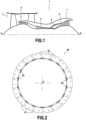
- FIG 1 represents, in section along a vertical plane passing through its main axis A, a dual-flow turbojet 1 according to the invention. It comprises, from upstream to downstream according to the circulation of the air flow, a blower 2, a low pressure compressor 3, a high pressure compressor 4, a combustion chamber 5, a high pressure turbine 6, and a low pressure turbine 7.
- FIG 2 illustrates the ring 60 of the high pressure turbine 6 defining the outer limit of the air stream within the high pressure turbine 6.
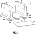
- This ring 60 is divided into several sectors 61 in CMC, substantially identical, connected by metal tabs sealing 62.
- FIG 3 illustrates such a sector 61: it comprises a vein wall 63, an upstream flange 64 and a downstream flange 65.
- the vein wall 63 having the shape of a cylinder sector, is configured to form jointly with the other sectors 61 a cylindrical ring of axis A.
- the vein wall has an internal main face 63p, intended to delimit the air vein, an upstream end face 63m, a downstream end face 63v and two inter-sector lateral faces 63i.
- a groove 66 is made in each inter-sector face 63i. These grooves 66, extending axially over practically the entire length of the vein wall 63, have in this example a depth of 3 mm and a width of 0.5 mm. The internal walls of the grooves 66 have an arithmetic average roughness Ra of less than 1.6 ⁇ m.
- the tongue 62 made of a nickel or cobalt base alloy, has a length substantially equal to that of the groove 66 and a thickness slightly less than the latter in order to allow the insertion of the tongue 62 into a groove 66.
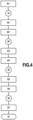
- FIG 4 And 5 illustrate the different stages of an example of a process according to the presentation making it possible to manufacture such a ring sector 61 in CMC, that is to say in a composite material with a ceramic matrix.
- the FIG 5 is a schematic representation not taking into account the exact shape of the part.
- the process begins with weaving E1 of a fibrous preform 10 which will play the role of fibrous reinforcement of sector 61.
- This preform 10 is preferably woven using a 3D weaving technique, known elsewhere, for example with an interlock type weave .
- the preform 10 is woven with silicon carbide SiC fibers.
- the preform 10 is shaped and undergoes an interphase deposition step E2, known elsewhere, for example of the chemical vapor deposition type (also known as CVD for “Chemical Vapor Deposition”).
- the deposited interphase material is silicon carbide SiC.
- a SiC sheath is therefore formed around the fibers of the preform 10, which consolidates the preform 10 and blocks the shape given during shaping.
- the fibers of the preform 10 are therefore coated with an interphase sheath but the preform 10 still remains very porous.
- a trench 18 is cut in each side face 19 of the preform 10 corresponding to the inter-sector faces 63i of the final sector 61.
- a consolidated and cut preform 10' is then obtained.
- the consolidated and cut preform 10' is then transferred into a mold to undergo a step E3 of injecting a ceramic slip.
- the slip comprises a solvent, here water, a ceramic powder, here silicon carbide SiC, and an organic binder, here polyvinyl alcohol.
- the concentration of the SiC powder in the slip is approximately 20% by volume.
- the concentration of the binder is 1% by mass relative to the mass of SiC powder in slip.
- the mold is designed so as to match the shape of the preform 10' while leaving a free volume inside the trenches 18.
- the slip when the slip is injected into the mold, it impregnates on the one hand the preform 10' and on the other hand fills the free volume inside the trenches 18 of the preform 10'.
- a drying step E4 is then carried out to remove the solvent from the slip.
- it is a lyophilization step (also known by its English name “freeze-drying"), during which the mold is suddenly brought to a negative temperature in order to solidify the solvent then gradually reheated to very low pressure so as to cause the sublimation of the solvent practically without alteration of the surrounding materials, the solvent in the gas phase then being eliminated using a cold trap for example.
- the drying step E4 could comprise a step of controlled evaporation of the solvent during which the temperature of the enclosure is gradually increased from 50 to 120 ° C by an increase of 1 to 5 ° C. C/min, preferably 1°C/min.
- the drying step E4 could include a Deliquoring step carried out under a pressure of between 50 and 100 mbar, for 1 to 2 hours.
- the ceramic particles of the slip settle and are deposited on the fibers of the preform as the solvent is eliminated, thus filling part of the porosities of the preform 10. Furthermore, within the free volume, the ceramic particles agglomerate and bond to each other under the effect in particular of the organic binder.
- the green part 20 thus obtained then undergoes a step E5 of annealing and pre-sintering making it possible to strengthen the connections between the particles of the ceramic powder and therefore to reinforce the strength of the green part 20, especially in its second part 21.
- the annealing takes place under neutral gas, for example argon, at a temperature of 1400°C for 1 hour.
- neutral gas for example argon
- the raw part 20 is demolded and transferred to undergo a densification step E6.
- a liquid densification material here silicon Si
- the densification material then penetrates by capillary action within the green part 20, whether in its first part 21 or its second part 22, and fills the residual porosities of the raw part 20.
- the raw part 30 After cooling and solidification of the densification material, we obtain a raw part 30 having no more, or practically no more, porosities. Analogous to the raw part, the raw part 30 has a first part 31, provided with the reinforcement formed by the fibrous preform 10 and embedded in the matrix, and a second part 32, located within the trenches 18, devoid of the fibrous reinforcement 10 and consisting exclusively of matrix.
- FIG 6 illustrates a second embodiment of the proposed method. Only the differences with the first example will be described. In particular, the succession of the different stages remains identical to that of the FIG. 3 , only step E3 of injecting the slip being implemented differently.
- the process begins with weaving E1 of a fibrous preform 110 similar to that of the first example. It undergoes an interphase deposition step E2 similar to that of the first example then a machining step E2' similar to that of the first example leading to obtaining a consolidated and cut preform 110' provided with trenches 118 made in each of its side faces 119.
- the consolidated and cut preform 110' is then transferred into a mold to undergo a step E3 of injecting a ceramic slip.
- the slip comprises a solvent, here water, a ceramic powder, here silicon carbide SiC, and an organic binder, here polyvinyl alcohol, with identical concentrations.
- the mold used has a different shape from that of the first example. Indeed, it is designed to match the shape of the preform 110' while leaving a free volume inside the trenches 18 but also on the surface of the side faces 119 of the preform.
- the slip when the slip is injected into the mold, it impregnates on the one hand the preform 110' and on the other hand fills the free volume left inside the trenches 118 and in front of the side faces 119 of the preform 110'.
- a drying step E4 is then carried out in a manner similar to the first example.
- a green part 120 having a first part 121 provided with the reinforcement formed by the fibrous preform 110 and a second part 122, devoid of the fibrous reinforcement 110 and made up of ceramic powder agglomerate with a compaction rate greater than 50%.
- the main surfaces 119 of the preform 110 are then found at the interface between these first and second parts 121, 122 of the raw part 120.
- the green part 120 thus obtained then undergoes an annealing and pre-sintering step E5 similar to the first example. Once this step E5 is completed, the raw part 120 is demolded and transferred to undergo a densification step E6 similar to the first example.
- the raw part 130 After cooling and solidification of the densification material, we obtain a raw part 130 having no more, or practically no more, porosities. Analogous to the raw part, the raw part 130 has a first part 131, provided with the reinforcement formed by the fibrous preform 110 and embedded in the matrix, and a second part 132, devoid of the fibrous reinforcement 110 and consisting exclusively of matrix.
- the layers of matrix devoid of fibrous reinforcement obtained on the surface of the side faces 119 of the preform 110 make it possible to protect the inter-sector surfaces 163i of the final sector 161 without it being necessary to deposit a thermal coating there. specific.
Landscapes
- Engineering & Computer Science (AREA)
- Chemical & Material Sciences (AREA)
- Ceramic Engineering (AREA)
- Manufacturing & Machinery (AREA)
- Materials Engineering (AREA)
- Structural Engineering (AREA)
- Organic Chemistry (AREA)
- Mechanical Engineering (AREA)
- General Engineering & Computer Science (AREA)
- Inorganic Chemistry (AREA)
- Chemical Kinetics & Catalysis (AREA)
- Composite Materials (AREA)
- Combustion & Propulsion (AREA)
- Turbine Rotor Nozzle Sealing (AREA)
Description
- Le présent exposé concerne un procédé de fabrication d'une pièce en CMC, c'est-à-dire en matériau composite à matrice céramique, munie d'au moins une découpe.
- Un tel procédé de fabrication peut notamment être utilisé dans le domaine de l'aéronautique afin de fabriquer des pièces capables de résister à de hautes températures. Il peut notamment s'agir de secteurs d'un organe cylindrique d'une turbomachine, telle qu'un turboréacteur d'aéronef, et tout particulièrement de secteurs d'anneau de turbine, pour ne citer que ces exemples.
- Les turbines de turboréacteur comprennent un anneau permettant de réaliser la veine externe de la turbine. Classiquement, cet anneau est divisé en plusieurs secteurs assemblés les uns à côté des autres de sorte à former un anneau complet. Dès lors, afin d'assurer l'étanchéité de l'anneau, des rainures sont pratiquées sur les faces inter-secteurs de chaque secteur et des languettes métalliques sont insérées dans ces rainures afin de relier les secteurs deux à deux.
- En raison des très fortes températures régnant dans ces turbines, les secteurs d'anneau sont réalisés en CMC. Les languettes métalliques sont quant à elles réalisées généralement en alliage base nickel ou cobalt, ou à base d'autres matériaux résistant à des températures élevées.
- Les rainures, possédant typiquement une largeur de 0,4 à 1 mm, sont habituellement réalisées par usinage. Toutefois, cette méthode présente l'inconvénient de mettre à nu les fibres du renfort fibreux présent au sein du secteur en CMC, ce qui entraîne une corrosion et/ou une oxydation accélérée de la pièce ainsi soumise à de fortes températures.
- Or, en raison de leur profondeur importante par rapport à leur largeur réduite, il est difficile si ce n'est impossible de déposer un revêtement de protection au fond des rainures par voie de projection thermique.
- De plus, l'usinage au sein du renfort fibreux de secteur d'anneau implique que l'état de surface des parois internes des rainures est assez irrégulier, avec notamment une rugosité moyenne arithmétique Ra supérieure à 6 µm, ce qui entraîne des défauts d'étanchéité entre les languettes métalliques et les secteurs d'anneau. On connaît également le document
WO 2016/001343 , qui décrit un procédé de fabrication d'une pièce composite CMC munie d'un revêtement de surface,WO 2010/103213 qui décrit un anneau de turbine comprenant une pluralité de secteurs en CMC, etWO 2011/070294 , qui décrit une aube de turbine en CMC. - Il existe donc un réel besoin pour un procédé de fabrication d'une pièce en CMC ainsi qu'une telle pièce en CMC qui soient dépourvus, au moins en partie, des inconvénients inhérents à la méthode connue précitée.
- Le présent exposé concerne un procédé de fabrication d'une pièce en CMC munie d'au moins une découpe, comprenant les étapes suivantes :
- fourniture d'un renfort fibreux,
- formation d'une cavité dans une portion du renfort fibreux,
- injection d'une barbotine comprenant au moins une poudre céramique et un solvant, la barbotine étant injectée de manière à imprégner le renfort fibreux et à remplir la cavité du renfort fibreux,
- séchage de l'ensemble obtenu,
- densification par infiltration d'un matériau de densification liquide et solidification dudit matériau de densification,
- usinage d'au moins une découpe dans la pièce brute obtenue au sein du volume correspondant à la cavité du renfort fibreux.
- Ainsi, dans un tel procédé, la barbotine est injectée à la fois dans le renfort fibreux et dans le volume de la cavité formée dans le renfort fibreux. En conséquence, après séchage et densification de l'ensemble, on obtient une pièce brute possédant une première partie formée par le renfort fibreux noyé dans la matrice céramique et une deuxième partie, localisée au sein de la cavité du renfort, formée par de la matrice céramique dépourvue de renfort.
- Dès lors, le volume situé au sein de la cavité du renfort fibreux est totalement dépourvu de fibres : il est donc possible d'usiner cette deuxième partie facilement et sans contraintes, sans mettre à nu de fibres du renfort fibreux. On réduit ainsi le risque de corrosion et/ou d'oxydation de la pièce, ce qui augmente sa durée de vie et réduit le recours à la maintenance.
- De plus, en l'absence de fibres tissées, la structure de la deuxième partie de la pièce brute est plus homogène que la première partie, ce qui permet d'obtenir un état de surface plus régulier lors de l'usinage de la découpe de la pièce finale. On obtient ainsi un meilleur contact entre un élément inséré dans la rainure (une languette d'étanchéité par exemple) et cette dernière, ce qui permet d'atteindre par exemple un niveau d'étanchéité plus important.
- Dans le présent exposé, les termes « axial », « radial », « tangentiel », « intérieur », « extérieur » et leurs dérivés sont définis par rapport à l'axe principal de la turbomachine ; on entend par « plan axial » un plan passant par l'axe principal de la turbomachine et par « plan radial » un plan perpendiculaire à cet axe principal ; enfin, les termes « amont » et « aval » sont définis par rapport à la circulation de l'air dans la turbomachine.
- Dans certains modes de réalisation, le renfort fibreux est réalisé par tissage, de préférence par tissage 3D. Le tissage 3D permet notamment d'obtenir des renforts fibreux possédant des géométries complexes en un seul tenant, assurant ainsi une très bonne tenue mécanique à la pièce finale.
- Dans certains modes de réalisation, le renfort fibreux comprend des fibres de SiC, de préférence au moins 50% de fibres de SiC, de préférence encore au moins 95% de fibres de SiC. Toutefois, n'importe quel type de fibre céramique pourrait également être utilisé et notamment des fibres de carbone.
- Dans certains modes de réalisation, au cours de l'étape d'injection de la barbotine, la barbotine est injectée de manière à remplir en outre un volume situé à la surface de la portion du renfort fibreux dans laquelle a été formée la cavité. Ceci permet de protéger complètement la face de la pièce portant la découpe, y compris sur les bords de ladite découpe. En particulier, ceci permet une meilleure densification en surface de cette portion de préforme.
- Dans certains modes de réalisation, la poudre céramique de la barbotine comprend du SiC, de préférence au moins 50% de SiC, de préférence encore au moins 95% de SiC. Toutefois, n'importe quel type de poudre céramique pourrait également être utilisée et notamment du B, B4C, TiC, ZrC, BN, Si3N4, ou encore TiSi2.
- Dans certains modes de réalisation, le diamètre moyen des particules de la poudre céramique de la barbotine est compris entre 0,1 µm et 10 µm, de préférence entre 0,5 µm et 5 µm. La réalisation d'une partie de pièce crue formée exclusivement de matrice céramique, hors du renfort fibreux, est délicate en raison du taux de porosité élevé laissé dans cette partie de la pièce crue après l'élimination du solvant. Ainsi, avant sa densification, cette deuxième partie de la pièce crue est très fragile et peut facilement s'effriter, se fissurer voire se décrocher complètement de la première partie munie du renfort fibreux, tout particulièrement si cette deuxième partie s'étend non seulement au sein de la cavité du renfort fibreux mais également en surface de ce dernier. Plusieurs paramètres permettent de renforcer cette deuxième partie de la pièce crue afin de réduire les risques d'endommagement mentionnés ci-dessus : parmi ces derniers figure le diamètre des particules de la poudre céramique. Ainsi, les inventeurs ont constaté que les gammes de diamètre proposées ci-dessus facilitaient la mise en oeuvre du présent procédé.
- Dans certains modes de réalisation, le diamètre D50 des particules de la poudre céramique de la barbotine est compris entre 0,5 et 2µm. La distribution des particules de poudre peut être monomodale ou bimodale.
- Dans certains modes de réalisation, le diamètre d10 des particules de la poudre céramique de la barbotine est supérieur à 0,1 µm.
- Dans certains modes de réalisation, le diamètre d90 des particules de la poudre céramique de la barbotine est inférieur à 4 µm.
- Dans certains modes de réalisation, le solvant de la barbotine est un solvant aqueux.
- Dans certains modes de réalisation, la barbotine comprend un liant organique. Ce liant permet une meilleure tenue de la barbotine puis de la deuxième partie de pièce crue obtenue suite au séchage de la barbotine : ceci facilite notamment le démoulage de la pièce crue puis sa manipulation sans dommages.
- Dans certains modes de réalisation, ledit liant organique comprend au moins un des composés suivants : alcool polyvinylique (PVA) ; polyvinylpyrrolidone (PvP) ; polyéthylène imine et polyéthylène glycol (PEG). Ces différents composés augmentent en effet sensiblement la tenue de la pièce crue.
- Dans certains modes de réalisation, la concentration massique dudit liant organique par rapport à la masse de poudre est comprise entre 0,5 et 10%, de préférence entre 1 et 5%. De telles concentrations assurent une bonne efficacité au liant et donc une bonne tenue de la pièce crue.
- Dans certains modes de réalisation, la barbotine comprend en outre un plastifiant et/ou un dispersant. Il peut notamment s'agir d'un plastifiant, ou d'un liant, du type PVA, PEG ou PvP. Un plastifiant augmente la tenue mécanique du cru céramique après injection : il permet d'abaisser la viscosité de la barbotine et apporte une souplesse au matériau cru. En ce qui concerne les dispersants, il peut s'agir de bases possédant un pH compris entre 8 et 12, de préférence entre 9 et 11, par exemple du type hydroxyde de tétraéthylammonium (TEAH), hydroxyde de tétraéméthylammonium (TMAH), ou hydroxyde de sodium (NaOH), ou des systèmes électrostériques, par exemple du type polyétherimide (PEI). Ces dispersants permettent de maintenir les particules en suspension par dispersion électrostatique.
- Dans certains modes de réalisation, au moins un consommable est mis en place dans l'outillage contenant le renfort fibreux au cours de l'étape d'injection de la barbotine. Un tel consommable permet d'obtenir un état de surface prédéterminé dans la zone où il est placé. Divers consommables peuvent être utilisés et notamment des tissus, des élastomères et/ou des clinquants métalliques. Selon la zone de l'outillage, le consommable peut être poreux, ou non.
- Dans certains modes de réalisation, l'étape de séchage comprend une étape de lyophilisation. Une telle étape de lyophilisation permet de réduire le risque de fissuration de la deuxième partie de la pièce crue lors de l'étape de séchage. Elle permet également d'assurer une bonne cohésion entre les première et deuxième parties de la pièce crue.
- Dans certains modes de réalisation, l'étape de séchage comprend une étape d'évaporation contrôlée avec une rampe de températures croissante. Une telle évaporation contrôlée permet de maîtriser l'élimination du solvant, réduisant ainsi le risque de fissuration au cours de l'étape de séchage.
- Dans certains modes de réalisation, l'étape de séchage comprend une étape de séchage du type Deliquoring au cours de laquelle la pièce est séchée par application d'un gradient de pression.
- Dans certains modes de réalisation, la pente de la rampe de températures de l'étape d'évaporation contrôlée est comprise entre 1 et 5°C/min.
- Dans certains modes de réalisation, la rampe de températures de l'étape d'évaporation contrôlée s'achève avec une température finale comprise entre 100 et 140°C, de préférence entre 115 et 125 °C.
- Dans certains modes de réalisation, la rampe de températures de l'étape d'évaporation contrôlée débute à une température initiale comprise entre 30 et 70°C, de préférence entre 45 et 65°C.
- Dans certains modes de réalisation, le taux de compaction de la poudre céramique hors du renfort fibreux à l'issue de l'étape de séchage est supérieur à 50%. Le taux de compaction correspond au taux de matière par rapport au volume de la pièce considérée : il traduit en particulier le taux de porosité de la pièce. Un tel taux de compaction assure une tenue suffisante à la deuxième partie de la pièce crue.
- Dans certains modes de réalisation, le matériau de densification comprend du Si, de préférence au moins 50% en masse de Si, de préférence encore au moins 95% en masse de Si.
- Dans certains modes de réalisation, le procédé comprend en outre une étape de recuit et de pré-frittage de la poudre céramique après l'étape d'injection de la barbotine et avant l'étape de densification. Ceci permet de renforcer la tenue de la pièce crue en créant des connexions entre les particules de poudre de céramique.
- Dans certains modes de réalisation, l'étape de recuit et de pré-frittage est menée à une température comprise entre 1200 et 1600°C, de préférence entre 1300°C et 1500°C, pendant une durée comprise entre 30 min et 2h, de préférence entre 45 min et 1h30.
- Dans certains modes de réalisation, l'étape de recuit et de pré-frittage est menée sous gaz neutre, par exemple sous Argon.
- Dans certains modes de réalisation, la découpe usinée dans la pièce brute est une rainure. Toutefois, il va de soi que tout autre type de découpe peut être envisagé, et notamment des alésages, des encoches, des épaulements, des cavités, des repères etc. Plusieurs découpes de types différents peuvent également être usinées dans la même pièce brute.
- Dans certains modes de réalisation, la rainure usinée dans la pièce brute possède une largeur inférieure à 1 mm.
- Dans certains modes de réalisation, la rainure usinée dans la pièce brute possède une profondeur au moins trois fois plus importante que sa largeur.
- Dans certains modes de réalisation, la rugosité moyenne arithmétique Ra des parois internes de la découpe usinée dans la pièce brute est inférieure à 5 µm, de préférence inférieure à 2 µm. Ceci permet à un élément inséré dans la découpe de s'appliquer plus étroitement contre la paroi de la découpe, assurant ainsi un niveau d'étanchéité plus élevé.
- Dans certains modes de réalisation, l'étape d'usinage est réalisée par fraisage, rectification et/ou électroérosion.
- Dans certains modes de réalisation, le procédé comprend en outre une étape de dépôt d'un revêtement de protection sur au moins une face de la pièce finale qui est dépourvue de découpe.
- Dans certains modes de réalisation, la face de la pièce finale dans laquelle a été usinée la découpe est dépourvue de revêtement de protection. Un tel revêtement est notamment rendu inutile lorsque la barbotine a été injectée également en surface de cette face du renfort final.
- Dans certains modes de réalisation, le procédé comprend en outre, avant l'étape d'injection de la barbotine, une étape de dépôt d'interphase prévue pour gainer les fibres du renfort fibreux avec un matériau d'interphase.
- Dans certains modes de réalisation, l'étape de dépôt d'interphase est réalisée par voie gazeuse.
- Dans certains modes de réalisation, le matériau d'interphase comprend du SiC et/ou du BN, de préférence au moins 50% de SiC, de préférence encore au moins 95% de SiC.
- Dans certains modes de réalisation, le procédé comprend en outre une étape de préparation. Il peut notamment s'agir d'une étape de sablage ou de toute autre étape permettant d'augmenter localement la rugosité de la surface de la pièce.
- Dans certains modes de réalisation, ladite pièce en CMC est une pièce aéronautique, par exemple une pièce de chambre de combustion ou de turbine. Il peut notamment s'agir d'un secteur d'anneau de turbine.
- Le présent exposé concerne également, sans toutefois la revendiquer, une pièce en CMC, munie d'au moins une découpe, obtenue à l'aide d'un procédé selon l'un quelconque des modes de réalisation précédents.
- Le présent exposé concerne en outre, sans toutefois la revendiquer, une turbine, comprenant un anneau comportant au moins deux secteurs d'anneau, muni chacun d'une rainure sur chacune de ses faces d'extrémité tangentielle, et une languette d'étanchéité engagée dans les rainures de deux secteurs d'anneau consécutifs, dans laquelle au moins un desdits secteurs d'anneau est une pièce en CMC selon l'un quelconque des modes de réalisation précédents.
- Le présent exposé concerne également, sans toutefois la revendiquer, une turbomachine comprenant au moins une pièce en CMC ou une turbine selon l'un quelconque des modes de réalisation précédents.
- Les caractéristiques et avantages précités, ainsi que d'autres, apparaîtront à la lecture de la description détaillée qui suit, d'exemples de réalisation du procédé proposé. Cette description détaillée fait référence aux dessins annexés.
- Les dessins annexés sont schématiques et visent avant tout à illustrer les principes de l'invention.
- Sur ces dessins, d'une figure (FIG) à l'autre, des éléments (ou parties d'élément) identiques sont repérés par les mêmes signes de référence. En outre, des éléments (ou parties d'élément) appartenant à des exemples de réalisation différents mais ayant une fonction analogue sont repérés sur les figures par des références numériques incrémentées de 100, 200, etc.
- La
FIG 1 est un plan en coupe d'une turbomachine selon le présent exposé. - La
FIG 2 est une vue schématique d'un anneau de turbine sectorisé. - La
FIG 3 est une vue en perspective d'un secteur d'anneau selon le présent exposé. - La
FIG 4 illustre les étapes successives d'un premier exemple de procédé selon l'exposé. - La
FIG 5 illustre l'évolution de la pièce au cours de ce premier exemple de procédé. - La
FIG 6 illustre l'évolution de la pièce au cours d'un deuxième exemple de procédé. - Afin de rendre plus concrète l'invention, des exemples de procédés sont décrits en détail ci-après, en référence aux dessins annexés. Il est rappelé que l'invention ne se limite pas à ces exemples.
- La
FIG 1 représente, en coupe selon un plan vertical passant par son axe principal A, un turboréacteur à double flux 1 selon l'invention. Il comporte, d'amont en aval selon la circulation du flux d'air, une soufflante 2, un compresseur basse pression 3, un compresseur haute pression 4, une chambre de combustion 5, une turbine haute pression 6, et une turbine basse pression 7. - La
FIG 2 illustre l'anneau 60 de la turbine haute pression 6 définissant la limite extérieure de la veine d'air au sein de la turbine haute pression 6. Cet anneau 60 est divisé en plusieurs secteurs 61 en CMC, sensiblement identiques, reliés par des languettes métalliques d'étanchéité 62. - La
FIG 3 illustre un tel secteur 61 : il comprend une paroi de veine 63, une bride amont 64 et une bride aval 65. La paroi de veine 63, ayant la forme d'un secteur de cylindre, est configurée pour former conjointement avec les autres secteurs 61 un anneau cylindrique d'axe A. La paroi de veine possède une face principale interne 63p, destinée à délimiter la veine d'air, une face d'extrémité amont 63m, une face d'extrémité aval 63v et deux face latérales inter-secteurs 63i. - Une rainure 66 est pratiquée dans chaque face inter-secteurs 63i. Ces rainures 66, s'étendant axialement sur pratiquement toute la longueur de la paroi de veine 63, possèdent dans cet exemple une profondeur de 3 mm et une largeur de 0,5 mm. Les parois internes des rainures 66 possèdent une rugosité arithmétique moyenne Ra inférieure à 1,6 µm.
- La languette 62, réalisée en alliage base nickel ou cobalt, possède une longueur sensiblement également à celle de la rainure 66 et une épaisseur légèrement inférieure à cette dernière afin de permettre l'insertion de la languette 62 dans une rainure 66.
- Les
FIG 4 et5 illustrent les différentes étapes d'un exemple de procédé selon l'exposé permettant de fabriquer un tel secteur d'anneau 61 en CMC, c'est-à-dire en matériau composite à matrice céramique. En particulier, laFIG 5 est une représentation schématique ne tenant pas compte de la forme exacte de la pièce. - Le procédé débute avec le tissage E1 d'une préforme fibreuse 10 qui jouera le rôle de renfort fibreux du secteur 61. Cette préforme 10 est de préférence tissée selon une technique de tissage 3D, connue par ailleurs, par exemple avec une armure du type interlock. Dans cet exemple, la préforme 10 est tissée avec des fibres de carbure de silicium SiC.
- Une fois la préforme 10 terminée, elle est mise en forme et subit une étape E2 de dépôt d'interphase, connue par ailleurs, par exemple du type dépôt chimique en phase vapeur (également connue sous le nom CVD pour « Chemical Vapor Déposition »). Dans cet exemple, le matériau d'interphase déposé est du carbure de silicium SiC. Une gaine de SiC se forme donc autour des fibres de la préforme 10, ce qui consolide la préforme 10 et bloque la forme donnée lors de la mise en forme. A l'issue de cette étape E2 de dépôt d'interphase, les fibres de la préforme 10 sont donc revêtues d'une gaine d'interphase mais la préforme 10 reste encore très poreuse.
- Au cours d'une étape d'usinage E2', une tranchée 18 est taillée dans chaque face latérale 19 de la préforme 10 correspondant aux faces inter-secteurs 63i du secteur final 61. On obtient alors une préforme consolidée et découpée 10'.
- La préforme consolidée et découpée 10' est alors transférée dans un moule pour subir une étape E3 d'injection d'une barbotine céramique. Dans cet exemple, la barbotine comprend un solvant, ici de l'eau, une poudre céramique, ici du carbure de silicium SiC, et un liant organique, ici de l'alcool polyvinylique.
- Dans cet exemple, la concentration de la poudre de SiC dans la barbotine est d'environ 20% en volume. La concentration du liant est pour sa part de 1% en masse par rapport à la masse de poudre de SiC en barbotine.
- Le moule est prévu pour sa part de manière à épouser la forme de la préforme 10' tout en laissant un volume libre à l'intérieur des tranchées 18. Ainsi, lorsque la barbotine est injectée dans le moule, elle imprègne d'une part la préforme 10' et remplit d'autre part le volume libre à l'intérieur des tranchées 18 de la préforme 10'.
- Une étape de séchage E4 est alors conduite pour éliminer le solvant de la barbotine. Il s'agit dans cet exemple d'une étape de lyophilisation (également connue sous son nom anglais de « freeze-drying »), au cours de laquelle le moule est porté brutalement à une température négative afin de solidifier le solvant puis réchauffé progressivement à très basse pression de manière à entraîner la sublimation du solvant pratiquement sans altération des matières environnantes, le solvant en phase gazeuse étant alors éliminé à l'aide d'un piège froid par exemple.
- Selon une variante, l'étape de séchage E4 pourrait comprendre une étape d'évaporation contrôlée du solvant au cours de laquelle la température de l'enceinte est progressivement portée de 50 à 120 °C à raison d'une augmentation de 1 à 5°C/min, de préférence 1°C/min.
- Selon encore une autre variante, l'étape de séchage E4 pourrait comprendre une étape de Deliquoring réalisée sous une pression comprise entre 50 et 100 mbar, pendant 1 à 2h.
- Au cours de l'étape de séchage E4, au sein de la préforme 10', les particules céramiques de la barbotine décantent et se déposent sur les fibres de la préforme à mesure que le solvant est éliminé, remplissant ainsi une part des porosités de la préforme 10. Par ailleurs, au sein du volume libre, les particules de céramique s'agglomèrent et se lient les unes aux autres sous l'effet notamment du liant organique.
- Ainsi, à l'issue de l'étape de séchage E4, on obtient une pièce crue 20 possédant une première partie 21 munie du renfort formé par la préforme fibreuse 10 et une deuxième partie 22, au sein des tranchées 18 et dépourvue du renfort fibreux 10, constituée de poudre céramique agglomérée possédant un taux de compaction supérieur à 50%.
- La pièce crue 20 ainsi obtenue subit ensuite une étape E5 de recuit et de pré-frittage permettant de renforcer les connexions entre les particules de la poudre céramique et donc de renforcer la tenue de la pièce crue 20, surtout dans sa deuxième partie 21.
- Dans cet exemple, le recuit a lieu sous gaz neutre, par exemple de l'argon, à une température de 1400 °C durant 1h.
- Une fois cette étape E5 terminée, la pièce crue 20 est démoulée est transférée pour subir une étape de densification E6. Au cours de cette étape de densification E6, un matériau de densification liquide, ici du silicium Si, est coulé sur la pièce crue 20 : le matériau de densification pénètre alors par capillarité au sein de la pièce crue 20, que ce soit dans sa première partie 21 ou sa deuxième partie 22, et remplit les porosités résiduelles de la pièce crue 20.
- Après refroidissement et solidification du matériau de densification, on obtient une pièce brute 30 ne possédant plus, ou pratiquement plus, de porosités. De manière analogue à la pièce crue, la pièce brute 30 possède une première partie 31, munie du renfort formé par la préforme fibreuse 10 et noyé dans la matrice, et une deuxième partie 32, située au sein des tranchées 18, dépourvue du renfort fibreux 10 et constituée exclusivement de matrice.
- Il est alors possible lors d'une étape E7 d'usinage, de préférence par électroérosion, de former les rainures 66 au sein de la deuxième partie 32, sans entamer le renfort fibreux 10, afin d'obtenir le secteur d'anneau final 61.
- Naturellement, d'autres usinages sont également possibles dans la deuxième partie 32 de la pièce brute 30 sans mettre à nu de fibres du renfort fibreux 10. De plus, certaines faces du secteur d'anneau 61, et notamment la face principale interne 63p, peuvent recevoir un revêtement thermique. Les faces inter-secteurs 63i sont pour leur part de préférence dépourvues d'un tel revêtement thermique.
- La
FIG 6 illustre un deuxième exemple de réalisation du procédé proposé. Seules les différences avec le premier exemple seront décrites. En particulier, la succession des différentes étapes reste identique à celle de laFIG. 3 , seule l'étape E3 d'injection de la barbotine étant mise en oeuvre différemment. - Ainsi, le procédé débute avec le tissage E1 d'une préforme fibreuse 110 analogue à celle du premier exemple. Elle subit une étape E2 de dépôt d'interphase analogue à celle du premier exemple puis une étape d'usinage E2' analogue à celle du premier exemple conduisant à l'obtention d'une préforme consolidée et découpée 110' munie de tranchées 118 pratiquées dans chacune de ses faces latérales 119.
- La préforme consolidée et découpée 110' est alors transférée dans un moule pour subir une étape E3 d'injection d'une barbotine céramique. De manière analogue à l'exemple précédent, la barbotine comprend un solvant, ici de l'eau, une poudre céramique, ici du carbure de silicium SiC, et un liant organique, ici de l'alcool polyvinylique, avec des concentrations identiques.
- En revanche, le moule utilisé possède une forme différente de celui du premier exemple. En effet, il est prévu de manière à épouser la forme de la préforme 110' tout en laissant un volume libre à l'intérieur des tranchées 18 mais également en surface des faces latérales 119 de la préforme. Ainsi, lorsque la barbotine est injectée dans le moule, elle imprègne d'une part la préforme 110' et remplit d'autre part le volume libre laissé à l'intérieur des tranchées 118 et devant les faces latérales 119 de la préforme 110'.
- Une étape de séchage E4 est alors conduite de manière analogue au premier exemple. Ainsi, à l'issue de l'étape de séchage E4, on obtient une pièce crue 120 possédant une première partie 121 munie du renfort formé par la préforme fibreuse 110 et une deuxième partie 122, dépourvue du renfort fibreux 110 et constituée de poudre céramique agglomérée possédant un taux de compaction supérieur à 50%. Les surfaces principales 119 de la préforme 110 se retrouvent alors à l'interface entre ces première et deuxième parties 121, 122 de la pièce crue 120.
- La pièce crue 120 ainsi obtenue subit ensuite une étape E5 de recuit et de pré-frittage analogue au premier exemple. Une fois cette étape E5 terminée, la pièce crue 120 est démoulée est transférée pour subir une étape de densification E6 analogue au premier exemple.
- Après refroidissement et solidification du matériau de densification, on obtient une pièce brute 130 ne possédant plus, ou pratiquement plus, de porosités. De manière analogue à la pièce crue, la pièce brute 130 possède une première partie 131, munie du renfort formé par la préforme fibreuse 110 et noyé dans la matrice, et une deuxième partie 132, dépourvue du renfort fibreux 110 et constituée exclusivement de matrice.
- En particulier, puisque les surfaces principales 119 de la préforme 110 s'étendaient à l'intérieur de la pièce crue 120, la densification au niveau de ces surfaces latérale 119 a pu être complète et homogène, sans effet de bord.
- Il est alors possible lors d'une étape E7 d'usinage, de préférence par électroérosion, de former au sein de la deuxième partie 132 les rainures 166, sans entamer le renfort fibreux 110, afin d'obtenir le secteur d'anneau final 161.
- Dans ce deuxième exemple, les couches de matrice dépourvue de renfort fibreux obtenues en surface des faces latérales 119 de la préforme 110 permettent de protéger les surfaces inter-secteurs 163i du secteur final 161 sans qu'il soit nécessaire d'y déposer un revêtement thermique spécifique.
- Bien que la présente invention ait été décrite en se référant à des exemples de réalisation spécifiques, il est évident que des modifications et des changements peuvent être effectués sur ces exemples sans sortir de la portée générale de l'invention telle que définie par les revendications. En particulier, des caractéristiques individuelles des différents modes de réalisation illustrés/mentionnés peuvent être combinées dans des modes de réalisation additionnels, à condition de rester dans la portée des revendications. Par conséquent, la description et les dessins doivent être considérés dans un sens illustratif plutôt que restrictif.
- Il est également évident que toutes les caractéristiques décrites en référence à un procédé sont transposables, seules ou en combinaison, à un dispositif, et inversement, toutes les caractéristiques décrites en référence à un dispositif sont transposables, seules ou en combinaison, à un procédé.
Claims (7)
- Procédé de fabrication d'une pièce en CMC munie d'au moins une découpe, comprenant les étapes suivantes :fourniture (E1) d'un renfort fibreux (10),formation (E2') d'une cavité (18) dans une portion du renfort fibreux (10),injection (E3) d'une barbotine comprenant au moins une poudre céramique et un solvant, la barbotine étant injectée de manière à imprégner le renfort fibreux (10) et à remplir la cavité (18) du renfort fibreux (10),séchage (E4) de l'ensemble obtenu,densification (E6) par infiltration d'un matériau de densification liquide et solidification dudit matériau de densification,usinage (E7) d'au moins une découpe (66) dans la pièce brute (30) obtenue au sein du volume correspondant à la cavité (18) du renfort fibreux (10).
- Procédé selon la revendication 1, dans lequel le renfort fibreux (10) est réalisé par tissage 3D (E1).
- Procédé selon la revendication 1 ou 2, dans lequel, au cours de l'étape d'injection de la barbotine (E3), la barbotine est injectée de manière à remplir en outre un volume situé à la surface de la portion (119) du renfort fibreux (110) dans laquelle a été formée la cavité (118).
- Procédé selon l'une quelconque des revendications 1 à 3, dans lequel la découpe (66) usinée dans la pièce brute (30) est une rainure possédant une largeur inférieure à 1 mm.
- Procédé selon l'une quelconque des revendications 1 à 4, dans lequel la découpe (66) usinée dans la pièce brute (30) est une rainure possédant une profondeur au moins trois fois plus importante que sa largeur.
- Procédé selon l'une quelconque des revendications 1 à 5, dans lequel l'étape d'usinage (E7) est réalisée par fraisage, rectification et/ou électroérosion.
- Procédé selon l'une quelconque des revendications 1 à 6, comprenant en outre une étape de dépôt d'un revêtement de protection sur au moins une face (63p) de la pièce finale (61) qui est dépourvue de découpe (66), et
dans lequel la face (63i) de la pièce finale (61) dans laquelle a été usinée la découpe (66) est dépourvue de revêtement de protection.
Applications Claiming Priority (2)
| Application Number | Priority Date | Filing Date | Title |
|---|---|---|---|
| FR1758751A FR3071247B1 (fr) | 2017-09-21 | 2017-09-21 | Procede de fabrication d'une piece en cmc |
| PCT/FR2018/052254 WO2019058046A1 (fr) | 2017-09-21 | 2018-09-13 | Procede de fabrication d'une piece en cmc |
Publications (2)
| Publication Number | Publication Date |
|---|---|
| EP3684742A1 EP3684742A1 (fr) | 2020-07-29 |
| EP3684742B1 true EP3684742B1 (fr) | 2023-10-25 |
Family
ID=60955166
Family Applications (1)
| Application Number | Title | Priority Date | Filing Date |
|---|---|---|---|
| EP18780190.7A Active EP3684742B1 (fr) | 2017-09-21 | 2018-09-13 | Procede de fabrication d'une piece en cmc |
Country Status (8)
| Country | Link |
|---|---|
| US (1) | US11753947B2 (fr) |
| EP (1) | EP3684742B1 (fr) |
| JP (1) | JP2020534240A (fr) |
| CN (1) | CN111315711A (fr) |
| BR (1) | BR112020005620A2 (fr) |
| CA (1) | CA3076441A1 (fr) |
| FR (1) | FR3071247B1 (fr) |
| WO (1) | WO2019058046A1 (fr) |
Families Citing this family (6)
| Publication number | Priority date | Publication date | Assignee | Title |
|---|---|---|---|---|
| US11105215B2 (en) * | 2019-11-06 | 2021-08-31 | Raytheon Technologies Corporation | Feather seal slot arrangement for a CMC BOAS assembly |
| FR3125528A1 (fr) * | 2021-07-26 | 2023-01-27 | Safran Ceramics | Procédé de fabrication d’une pièce épaisse en matériau composite CMC |
| US12071381B2 (en) * | 2021-12-03 | 2024-08-27 | Rtx Corporation | Ceramic matrix composite article and method of making the same |
| FR3130272A1 (fr) * | 2021-12-13 | 2023-06-16 | Safran Ceramics | Procédé de fabrication d’une pièce en CMC |
| US20230265763A1 (en) * | 2022-02-18 | 2023-08-24 | Raytheon Technologies Corporation | Ceramic matrix composite article and method of making the same |
| CN114542510A (zh) * | 2022-02-23 | 2022-05-27 | 中国航发沈阳发动机研究所 | 一种自适应变循环发动机风扇转子结构 |
Family Cites Families (18)
| Publication number | Priority date | Publication date | Assignee | Title |
|---|---|---|---|---|
| US4886766A (en) | 1987-08-10 | 1989-12-12 | Lanxide Technology Company, Lp | Method of making ceramic composite articles and articles made thereby |
| DE19934050A1 (de) * | 1999-07-19 | 2001-02-08 | Siemens Ag | Gasturbine |
| JP4586310B2 (ja) * | 2001-07-04 | 2010-11-24 | 株式会社Ihi | セラミックス複合部材の製造方法 |
| FR2882356B1 (fr) * | 2005-02-23 | 2008-08-15 | Snecma Propulsion Solide Sa | Procede de fabrication de piece en materiau composite a matrice ceramique et piece ainsi obtenue |
| FR2886640B1 (fr) * | 2005-06-02 | 2007-08-24 | Snecma Propulsion Solide Sa | Procede et preforme pour la realisation de pieces en materiau composite par densification cvi et pieces obtenues |
| JP5200730B2 (ja) * | 2008-07-25 | 2013-06-05 | イビデン株式会社 | セラミック複合部材 |
| RU2522264C2 (ru) * | 2009-03-09 | 2014-07-10 | Снекма | Сборка обоймы турбины |
| FR2953553B1 (fr) * | 2009-12-09 | 2012-02-03 | Snecma | Aube de turbine de turbomachine en composite a matrice ceramique avec evidements realises par usinage |
| US20130167374A1 (en) | 2011-12-29 | 2013-07-04 | General Electric Company | Process of producing ceramic matrix composites and ceramic matrix composites formed thereby |
| GB201205663D0 (en) * | 2012-03-30 | 2012-05-16 | Rolls Royce Plc | Effusion cooled shroud segment with an abradable system |
| CN103148764B (zh) * | 2013-03-11 | 2015-07-08 | 上海电气电站设备有限公司 | 汽轮机转子动叶围带间隙的测量方法及夹紧装置 |
| WO2016133579A1 (fr) * | 2015-02-18 | 2016-08-25 | Siemens Aktiengesellschaft | Revêtement de barrière thermique pour pièce de turbine présentant des éléments de rainure usinés en plusieurs parties en cascade pour isoler les fissures |
| FR3023212B1 (fr) * | 2014-07-03 | 2019-10-11 | Safran Ceramics | Procede de fabrication d'une piece revetue par un revetement de surface comportant un alliage |
| US10399911B2 (en) * | 2015-01-27 | 2019-09-03 | Rolls-Royce Corporation | Forming a surface layer of a ceramic matrix composite article |
| US10100656B2 (en) * | 2015-08-25 | 2018-10-16 | General Electric Company | Coated seal slot systems for turbomachinery and methods for forming the same |
| FR3041890B1 (fr) | 2015-10-05 | 2017-11-24 | Snecma | Procede de fabrication d'une piece en materiau composite par injection d'une barbotine chargee dans un moule poreux |
| RU2622067C1 (ru) | 2016-05-20 | 2017-06-09 | Федеральное Государственное Бюджетное Учреждение Науки Институт Химии Коми Научного Центра Уральского Отделения Российской Академии Наук | Способ получения керамического композита с мультиканальной структурой |
| CN107032824B (zh) * | 2017-05-11 | 2020-04-28 | 西安交通大学 | 一种定向组织陶瓷基复合材料零件的制造方法 |
-
2017
- 2017-09-21 FR FR1758751A patent/FR3071247B1/fr not_active Expired - Fee Related
-
2018
- 2018-09-13 CN CN201880071688.9A patent/CN111315711A/zh active Pending
- 2018-09-13 CA CA3076441A patent/CA3076441A1/fr active Pending
- 2018-09-13 WO PCT/FR2018/052254 patent/WO2019058046A1/fr not_active Ceased
- 2018-09-13 JP JP2020516555A patent/JP2020534240A/ja active Pending
- 2018-09-13 BR BR112020005620-0A patent/BR112020005620A2/pt not_active IP Right Cessation
- 2018-09-13 US US16/649,329 patent/US11753947B2/en active Active
- 2018-09-13 EP EP18780190.7A patent/EP3684742B1/fr active Active
Also Published As
| Publication number | Publication date |
|---|---|
| JP2020534240A (ja) | 2020-11-26 |
| BR112020005620A2 (pt) | 2020-10-06 |
| RU2020112740A (ru) | 2021-10-22 |
| US20200255344A1 (en) | 2020-08-13 |
| FR3071247B1 (fr) | 2019-09-20 |
| EP3684742A1 (fr) | 2020-07-29 |
| WO2019058046A1 (fr) | 2019-03-28 |
| CN111315711A (zh) | 2020-06-19 |
| FR3071247A1 (fr) | 2019-03-22 |
| RU2020112740A3 (fr) | 2021-11-26 |
| US11753947B2 (en) | 2023-09-12 |
| CA3076441A1 (fr) | 2019-03-28 |
Similar Documents
| Publication | Publication Date | Title |
|---|---|---|
| EP3684742B1 (fr) | Procede de fabrication d'une piece en cmc | |
| EP3448829B1 (fr) | Procédé de fabrication d'une pièce en matériau composite par injection d'une barbotine chargée dans une texture fibreuse | |
| EP2406466B1 (fr) | Ensemble d'anneau de turbine | |
| EP2118448B1 (fr) | Ensemble d'anneau de turbine pour turbine a gaz | |
| EP3298246B1 (fr) | Ensemble d'anneau de turbine permettant une dilatation thermique différentielle | |
| EP2683673B1 (fr) | Procede de fabrication d'un composite a matrice ceramique | |
| EP2137384A1 (fr) | Ensemble d'anneau de turbine pour turbine a gaz | |
| EP3996889B1 (fr) | Procede de fabrication d'une piece en materiau composite par injection d'une barbotine chargee dans une texture fibreuse | |
| WO2018162827A1 (fr) | Procédé de réalisation d'une préforme fibreuse consolidée | |
| EP4370260B1 (fr) | Noyau de moulage ameliore pour la fabrication de piece aeronautique creuse en cmo | |
| EP3793963B1 (fr) | Procédé de fabrication d'une pièce cmc | |
| WO2022129734A1 (fr) | Aube en materiau composite a matrice au moins partiellement ceramique | |
| WO2019058069A1 (fr) | Procede de fabrication d'une piece en cmc | |
| FR2949091A1 (fr) | Procede de realisation d'un disque aubage monobloc creux | |
| WO2022112696A1 (fr) | Piece en cmc et procede de fabrication d'une telle piece | |
| EP4370261B1 (fr) | Noyau de fonderie amélioré pour la fabrication de pièce aéronautique métallique creuse | |
| RU2793311C2 (ru) | Способ изготовления детали из композиционного материала с керамической матрицей | |
| EP4263214A1 (fr) | Procédé de fabrication d'une pièce en matériau composite à matrice céramique | |
| EP4237389B1 (fr) | Procede de fabrication d'une aube de turbomachine en materiau composite | |
| WO2026033181A1 (fr) | Procédé de fabrication d'un noyau pour un procédé de fonderie | |
| FR3125980A1 (fr) | Procédé de fabrication d’une pièce en matériau composite tissé 3D pour turbomachine | |
| EP4558769A1 (fr) | Outillage de maintien pour le frittage de preformes | |
| FR3163099A1 (fr) | Turbine de turbomachine comprenant un carter et un anneau de turbine | |
| EP4436939A1 (fr) | Noyau pour la réalisation de distributeur en composite à matrice céramique |
Legal Events
| Date | Code | Title | Description |
|---|---|---|---|
| STAA | Information on the status of an ep patent application or granted ep patent |
Free format text: STATUS: UNKNOWN |
|
| STAA | Information on the status of an ep patent application or granted ep patent |
Free format text: STATUS: THE INTERNATIONAL PUBLICATION HAS BEEN MADE |
|
| PUAI | Public reference made under article 153(3) epc to a published international application that has entered the european phase |
Free format text: ORIGINAL CODE: 0009012 |
|
| STAA | Information on the status of an ep patent application or granted ep patent |
Free format text: STATUS: REQUEST FOR EXAMINATION WAS MADE |
|
| 17P | Request for examination filed |
Effective date: 20200409 |
|
| AK | Designated contracting states |
Kind code of ref document: A1 Designated state(s): AL AT BE BG CH CY CZ DE DK EE ES FI FR GB GR HR HU IE IS IT LI LT LU LV MC MK MT NL NO PL PT RO RS SE SI SK SM TR |
|
| AX | Request for extension of the european patent |
Extension state: BA ME |
|
| DAV | Request for validation of the european patent (deleted) | ||
| DAX | Request for extension of the european patent (deleted) | ||
| STAA | Information on the status of an ep patent application or granted ep patent |
Free format text: STATUS: EXAMINATION IS IN PROGRESS |
|
| 17Q | First examination report despatched |
Effective date: 20220428 |
|
| GRAP | Despatch of communication of intention to grant a patent |
Free format text: ORIGINAL CODE: EPIDOSNIGR1 |
|
| STAA | Information on the status of an ep patent application or granted ep patent |
Free format text: STATUS: GRANT OF PATENT IS INTENDED |
|
| RIC1 | Information provided on ipc code assigned before grant |
Ipc: B29C 70/48 20060101ALI20230328BHEP Ipc: F23R 3/60 20060101ALI20230328BHEP Ipc: F23R 3/00 20060101ALI20230328BHEP Ipc: F02K 1/82 20060101ALI20230328BHEP Ipc: C04B 35/565 20060101ALI20230328BHEP Ipc: C04B 35/626 20060101ALI20230328BHEP Ipc: C04B 35/628 20060101ALI20230328BHEP Ipc: C04B 35/634 20060101ALI20230328BHEP Ipc: C04B 35/56 20060101ALI20230328BHEP Ipc: C04B 35/563 20060101ALI20230328BHEP Ipc: C04B 35/58 20060101ALI20230328BHEP Ipc: C04B 35/583 20060101ALI20230328BHEP Ipc: C04B 35/584 20060101ALI20230328BHEP Ipc: C04B 35/573 20060101ALI20230328BHEP Ipc: F01D 5/28 20060101ALI20230328BHEP Ipc: F01D 9/04 20060101ALI20230328BHEP Ipc: F01D 11/00 20060101ALI20230328BHEP Ipc: F01D 25/24 20060101ALI20230328BHEP Ipc: C04B 35/80 20060101AFI20230328BHEP |
|
| INTG | Intention to grant announced |
Effective date: 20230414 |
|
| GRAS | Grant fee paid |
Free format text: ORIGINAL CODE: EPIDOSNIGR3 |
|
| GRAA | (expected) grant |
Free format text: ORIGINAL CODE: 0009210 |
|
| STAA | Information on the status of an ep patent application or granted ep patent |
Free format text: STATUS: THE PATENT HAS BEEN GRANTED |
|
| AK | Designated contracting states |
Kind code of ref document: B1 Designated state(s): AL AT BE BG CH CY CZ DE DK EE ES FI FR GB GR HR HU IE IS IT LI LT LU LV MC MK MT NL NO PL PT RO RS SE SI SK SM TR |
|
| REG | Reference to a national code |
Ref country code: GB Ref legal event code: FG4D Free format text: NOT ENGLISH |
|
| REG | Reference to a national code |
Ref country code: CH Ref legal event code: EP |
|
| REG | Reference to a national code |
Ref country code: DE Ref legal event code: R096 Ref document number: 602018060025 Country of ref document: DE |
|
| REG | Reference to a national code |
Ref country code: IE Ref legal event code: FG4D Free format text: LANGUAGE OF EP DOCUMENT: FRENCH |
|
| REG | Reference to a national code |
Ref country code: LT Ref legal event code: MG9D |
|
| REG | Reference to a national code |
Ref country code: NL Ref legal event code: MP Effective date: 20231025 |
|
| REG | Reference to a national code |
Ref country code: AT Ref legal event code: MK05 Ref document number: 1624511 Country of ref document: AT Kind code of ref document: T Effective date: 20231025 |
|
| PG25 | Lapsed in a contracting state [announced via postgrant information from national office to epo] |
Ref country code: NL Free format text: LAPSE BECAUSE OF FAILURE TO SUBMIT A TRANSLATION OF THE DESCRIPTION OR TO PAY THE FEE WITHIN THE PRESCRIBED TIME-LIMIT Effective date: 20231025 |
|
| PG25 | Lapsed in a contracting state [announced via postgrant information from national office to epo] |
Ref country code: GR Free format text: LAPSE BECAUSE OF FAILURE TO SUBMIT A TRANSLATION OF THE DESCRIPTION OR TO PAY THE FEE WITHIN THE PRESCRIBED TIME-LIMIT Effective date: 20240126 |
|
| PG25 | Lapsed in a contracting state [announced via postgrant information from national office to epo] |
Ref country code: IS Free format text: LAPSE BECAUSE OF FAILURE TO SUBMIT A TRANSLATION OF THE DESCRIPTION OR TO PAY THE FEE WITHIN THE PRESCRIBED TIME-LIMIT Effective date: 20240225 |
|
| PG25 | Lapsed in a contracting state [announced via postgrant information from national office to epo] |
Ref country code: LT Free format text: LAPSE BECAUSE OF FAILURE TO SUBMIT A TRANSLATION OF THE DESCRIPTION OR TO PAY THE FEE WITHIN THE PRESCRIBED TIME-LIMIT Effective date: 20231025 |
|
| PG25 | Lapsed in a contracting state [announced via postgrant information from national office to epo] |
Ref country code: AT Free format text: LAPSE BECAUSE OF FAILURE TO SUBMIT A TRANSLATION OF THE DESCRIPTION OR TO PAY THE FEE WITHIN THE PRESCRIBED TIME-LIMIT Effective date: 20231025 |
|
| PG25 | Lapsed in a contracting state [announced via postgrant information from national office to epo] |
Ref country code: ES Free format text: LAPSE BECAUSE OF FAILURE TO SUBMIT A TRANSLATION OF THE DESCRIPTION OR TO PAY THE FEE WITHIN THE PRESCRIBED TIME-LIMIT Effective date: 20231025 |
|
| PG25 | Lapsed in a contracting state [announced via postgrant information from national office to epo] |
Ref country code: LT Free format text: LAPSE BECAUSE OF FAILURE TO SUBMIT A TRANSLATION OF THE DESCRIPTION OR TO PAY THE FEE WITHIN THE PRESCRIBED TIME-LIMIT Effective date: 20231025 Ref country code: IS Free format text: LAPSE BECAUSE OF FAILURE TO SUBMIT A TRANSLATION OF THE DESCRIPTION OR TO PAY THE FEE WITHIN THE PRESCRIBED TIME-LIMIT Effective date: 20240225 Ref country code: GR Free format text: LAPSE BECAUSE OF FAILURE TO SUBMIT A TRANSLATION OF THE DESCRIPTION OR TO PAY THE FEE WITHIN THE PRESCRIBED TIME-LIMIT Effective date: 20240126 Ref country code: ES Free format text: LAPSE BECAUSE OF FAILURE TO SUBMIT A TRANSLATION OF THE DESCRIPTION OR TO PAY THE FEE WITHIN THE PRESCRIBED TIME-LIMIT Effective date: 20231025 Ref country code: BG Free format text: LAPSE BECAUSE OF FAILURE TO SUBMIT A TRANSLATION OF THE DESCRIPTION OR TO PAY THE FEE WITHIN THE PRESCRIBED TIME-LIMIT Effective date: 20240125 Ref country code: AT Free format text: LAPSE BECAUSE OF FAILURE TO SUBMIT A TRANSLATION OF THE DESCRIPTION OR TO PAY THE FEE WITHIN THE PRESCRIBED TIME-LIMIT Effective date: 20231025 Ref country code: PT Free format text: LAPSE BECAUSE OF FAILURE TO SUBMIT A TRANSLATION OF THE DESCRIPTION OR TO PAY THE FEE WITHIN THE PRESCRIBED TIME-LIMIT Effective date: 20240226 |
|
| PG25 | Lapsed in a contracting state [announced via postgrant information from national office to epo] |
Ref country code: SE Free format text: LAPSE BECAUSE OF FAILURE TO SUBMIT A TRANSLATION OF THE DESCRIPTION OR TO PAY THE FEE WITHIN THE PRESCRIBED TIME-LIMIT Effective date: 20231025 Ref country code: RS Free format text: LAPSE BECAUSE OF FAILURE TO SUBMIT A TRANSLATION OF THE DESCRIPTION OR TO PAY THE FEE WITHIN THE PRESCRIBED TIME-LIMIT Effective date: 20231025 Ref country code: PL Free format text: LAPSE BECAUSE OF FAILURE TO SUBMIT A TRANSLATION OF THE DESCRIPTION OR TO PAY THE FEE WITHIN THE PRESCRIBED TIME-LIMIT Effective date: 20231025 Ref country code: NO Free format text: LAPSE BECAUSE OF FAILURE TO SUBMIT A TRANSLATION OF THE DESCRIPTION OR TO PAY THE FEE WITHIN THE PRESCRIBED TIME-LIMIT Effective date: 20240125 Ref country code: LV Free format text: LAPSE BECAUSE OF FAILURE TO SUBMIT A TRANSLATION OF THE DESCRIPTION OR TO PAY THE FEE WITHIN THE PRESCRIBED TIME-LIMIT Effective date: 20231025 Ref country code: HR Free format text: LAPSE BECAUSE OF FAILURE TO SUBMIT A TRANSLATION OF THE DESCRIPTION OR TO PAY THE FEE WITHIN THE PRESCRIBED TIME-LIMIT Effective date: 20231025 |
|
| PG25 | Lapsed in a contracting state [announced via postgrant information from national office to epo] |
Ref country code: DK Free format text: LAPSE BECAUSE OF FAILURE TO SUBMIT A TRANSLATION OF THE DESCRIPTION OR TO PAY THE FEE WITHIN THE PRESCRIBED TIME-LIMIT Effective date: 20231025 |
|
| PG25 | Lapsed in a contracting state [announced via postgrant information from national office to epo] |
Ref country code: CZ Free format text: LAPSE BECAUSE OF FAILURE TO SUBMIT A TRANSLATION OF THE DESCRIPTION OR TO PAY THE FEE WITHIN THE PRESCRIBED TIME-LIMIT Effective date: 20231025 |
|
| REG | Reference to a national code |
Ref country code: DE Ref legal event code: R097 Ref document number: 602018060025 Country of ref document: DE |
|
| PG25 | Lapsed in a contracting state [announced via postgrant information from national office to epo] |
Ref country code: SK Free format text: LAPSE BECAUSE OF FAILURE TO SUBMIT A TRANSLATION OF THE DESCRIPTION OR TO PAY THE FEE WITHIN THE PRESCRIBED TIME-LIMIT Effective date: 20231025 |
|
| PG25 | Lapsed in a contracting state [announced via postgrant information from national office to epo] |
Ref country code: SM Free format text: LAPSE BECAUSE OF FAILURE TO SUBMIT A TRANSLATION OF THE DESCRIPTION OR TO PAY THE FEE WITHIN THE PRESCRIBED TIME-LIMIT Effective date: 20231025 Ref country code: SK Free format text: LAPSE BECAUSE OF FAILURE TO SUBMIT A TRANSLATION OF THE DESCRIPTION OR TO PAY THE FEE WITHIN THE PRESCRIBED TIME-LIMIT Effective date: 20231025 Ref country code: RO Free format text: LAPSE BECAUSE OF FAILURE TO SUBMIT A TRANSLATION OF THE DESCRIPTION OR TO PAY THE FEE WITHIN THE PRESCRIBED TIME-LIMIT Effective date: 20231025 Ref country code: IT Free format text: LAPSE BECAUSE OF FAILURE TO SUBMIT A TRANSLATION OF THE DESCRIPTION OR TO PAY THE FEE WITHIN THE PRESCRIBED TIME-LIMIT Effective date: 20231025 Ref country code: EE Free format text: LAPSE BECAUSE OF FAILURE TO SUBMIT A TRANSLATION OF THE DESCRIPTION OR TO PAY THE FEE WITHIN THE PRESCRIBED TIME-LIMIT Effective date: 20231025 Ref country code: DK Free format text: LAPSE BECAUSE OF FAILURE TO SUBMIT A TRANSLATION OF THE DESCRIPTION OR TO PAY THE FEE WITHIN THE PRESCRIBED TIME-LIMIT Effective date: 20231025 Ref country code: CZ Free format text: LAPSE BECAUSE OF FAILURE TO SUBMIT A TRANSLATION OF THE DESCRIPTION OR TO PAY THE FEE WITHIN THE PRESCRIBED TIME-LIMIT Effective date: 20231025 |
|
| PLBE | No opposition filed within time limit |
Free format text: ORIGINAL CODE: 0009261 |
|
| STAA | Information on the status of an ep patent application or granted ep patent |
Free format text: STATUS: NO OPPOSITION FILED WITHIN TIME LIMIT |
|
| 26N | No opposition filed |
Effective date: 20240726 |
|
| PG25 | Lapsed in a contracting state [announced via postgrant information from national office to epo] |
Ref country code: SI Free format text: LAPSE BECAUSE OF FAILURE TO SUBMIT A TRANSLATION OF THE DESCRIPTION OR TO PAY THE FEE WITHIN THE PRESCRIBED TIME-LIMIT Effective date: 20231025 |
|
| PG25 | Lapsed in a contracting state [announced via postgrant information from national office to epo] |
Ref country code: SI Free format text: LAPSE BECAUSE OF FAILURE TO SUBMIT A TRANSLATION OF THE DESCRIPTION OR TO PAY THE FEE WITHIN THE PRESCRIBED TIME-LIMIT Effective date: 20231025 |
|
| PG25 | Lapsed in a contracting state [announced via postgrant information from national office to epo] |
Ref country code: MC Free format text: LAPSE BECAUSE OF FAILURE TO SUBMIT A TRANSLATION OF THE DESCRIPTION OR TO PAY THE FEE WITHIN THE PRESCRIBED TIME-LIMIT Effective date: 20231025 |
|
| REG | Reference to a national code |
Ref country code: CH Ref legal event code: PL |
|
| PG25 | Lapsed in a contracting state [announced via postgrant information from national office to epo] |
Ref country code: LU Free format text: LAPSE BECAUSE OF NON-PAYMENT OF DUE FEES Effective date: 20240913 |
|
| REG | Reference to a national code |
Ref country code: BE Ref legal event code: MM Effective date: 20240930 |
|
| PG25 | Lapsed in a contracting state [announced via postgrant information from national office to epo] |
Ref country code: BE Free format text: LAPSE BECAUSE OF NON-PAYMENT OF DUE FEES Effective date: 20240930 |
|
| PG25 | Lapsed in a contracting state [announced via postgrant information from national office to epo] |
Ref country code: CH Free format text: LAPSE BECAUSE OF NON-PAYMENT OF DUE FEES Effective date: 20240930 |
|
| PG25 | Lapsed in a contracting state [announced via postgrant information from national office to epo] |
Ref country code: IE Free format text: LAPSE BECAUSE OF NON-PAYMENT OF DUE FEES Effective date: 20240913 |
|
| PG25 | Lapsed in a contracting state [announced via postgrant information from national office to epo] |
Ref country code: FI Free format text: LAPSE BECAUSE OF FAILURE TO SUBMIT A TRANSLATION OF THE DESCRIPTION OR TO PAY THE FEE WITHIN THE PRESCRIBED TIME-LIMIT Effective date: 20231025 |
|
| PGFP | Annual fee paid to national office [announced via postgrant information from national office to epo] |
Ref country code: DE Payment date: 20250919 Year of fee payment: 8 |
|
| PGFP | Annual fee paid to national office [announced via postgrant information from national office to epo] |
Ref country code: GB Payment date: 20250923 Year of fee payment: 8 |
|
| PGFP | Annual fee paid to national office [announced via postgrant information from national office to epo] |
Ref country code: FR Payment date: 20250923 Year of fee payment: 8 |
|
| PG25 | Lapsed in a contracting state [announced via postgrant information from national office to epo] |
Ref country code: CY Free format text: LAPSE BECAUSE OF FAILURE TO SUBMIT A TRANSLATION OF THE DESCRIPTION OR TO PAY THE FEE WITHIN THE PRESCRIBED TIME-LIMIT; INVALID AB INITIO Effective date: 20180913 |
|
| PG25 | Lapsed in a contracting state [announced via postgrant information from national office to epo] |
Ref country code: HU Free format text: LAPSE BECAUSE OF FAILURE TO SUBMIT A TRANSLATION OF THE DESCRIPTION OR TO PAY THE FEE WITHIN THE PRESCRIBED TIME-LIMIT; INVALID AB INITIO Effective date: 20180913 |