EP3684044B1 - Camera module and assembly method therefor - Google Patents
Camera module and assembly method therefor Download PDFInfo
- Publication number
- EP3684044B1 EP3684044B1 EP18854093.4A EP18854093A EP3684044B1 EP 3684044 B1 EP3684044 B1 EP 3684044B1 EP 18854093 A EP18854093 A EP 18854093A EP 3684044 B1 EP3684044 B1 EP 3684044B1
- Authority
- EP
- European Patent Office
- Prior art keywords
- sub
- lens assembly
- lens
- assembly
- imaging
- Prior art date
- Legal status (The legal status is an assumption and is not a legal conclusion. Google has not performed a legal analysis and makes no representation as to the accuracy of the status listed.)
- Active
Links
Images


Classifications
-
- H—ELECTRICITY
- H04—ELECTRIC COMMUNICATION TECHNIQUE
- H04N—PICTORIAL COMMUNICATION, e.g. TELEVISION
- H04N23/00—Cameras or camera modules comprising electronic image sensors; Control thereof
- H04N23/50—Constructional details
-
- G—PHYSICS
- G02—OPTICS
- G02B—OPTICAL ELEMENTS, SYSTEMS OR APPARATUS
- G02B13/00—Optical objectives specially designed for the purposes specified below
- G02B13/001—Miniaturised objectives for electronic devices, e.g. portable telephones, webcams, PDAs, small digital cameras
- G02B13/0015—Miniaturised objectives for electronic devices, e.g. portable telephones, webcams, PDAs, small digital cameras characterised by the lens design
- G02B13/002—Miniaturised objectives for electronic devices, e.g. portable telephones, webcams, PDAs, small digital cameras characterised by the lens design having at least one aspherical surface
- G02B13/0045—Miniaturised objectives for electronic devices, e.g. portable telephones, webcams, PDAs, small digital cameras characterised by the lens design having at least one aspherical surface having five or more lenses
-
- G—PHYSICS
- G02—OPTICS
- G02B—OPTICAL ELEMENTS, SYSTEMS OR APPARATUS
- G02B27/00—Optical systems or apparatus not provided for by any of the groups G02B1/00 - G02B26/00, G02B30/00
- G02B27/62—Optical apparatus specially adapted for adjusting optical elements during the assembly of optical systems
-
- G—PHYSICS
- G02—OPTICS
- G02B—OPTICAL ELEMENTS, SYSTEMS OR APPARATUS
- G02B7/00—Mountings, adjusting means, or light-tight connections, for optical elements
- G02B7/02—Mountings, adjusting means, or light-tight connections, for optical elements for lenses
- G02B7/021—Mountings, adjusting means, or light-tight connections, for optical elements for lenses for more than one lens
-
- G—PHYSICS
- G02—OPTICS
- G02B—OPTICAL ELEMENTS, SYSTEMS OR APPARATUS
- G02B7/00—Mountings, adjusting means, or light-tight connections, for optical elements
- G02B7/02—Mountings, adjusting means, or light-tight connections, for optical elements for lenses
- G02B7/022—Mountings, adjusting means, or light-tight connections, for optical elements for lenses lens and mount having complementary engagement means, e.g. screw/thread
-
- G—PHYSICS
- G02—OPTICS
- G02B—OPTICAL ELEMENTS, SYSTEMS OR APPARATUS
- G02B7/00—Mountings, adjusting means, or light-tight connections, for optical elements
- G02B7/02—Mountings, adjusting means, or light-tight connections, for optical elements for lenses
- G02B7/023—Mountings, adjusting means, or light-tight connections, for optical elements for lenses permitting adjustment
-
- G—PHYSICS
- G02—OPTICS
- G02B—OPTICAL ELEMENTS, SYSTEMS OR APPARATUS
- G02B7/00—Mountings, adjusting means, or light-tight connections, for optical elements
- G02B7/02—Mountings, adjusting means, or light-tight connections, for optical elements for lenses
- G02B7/025—Mountings, adjusting means, or light-tight connections, for optical elements for lenses using glue
-
- G—PHYSICS
- G02—OPTICS
- G02B—OPTICAL ELEMENTS, SYSTEMS OR APPARATUS
- G02B7/00—Mountings, adjusting means, or light-tight connections, for optical elements
- G02B7/02—Mountings, adjusting means, or light-tight connections, for optical elements for lenses
- G02B7/04—Mountings, adjusting means, or light-tight connections, for optical elements for lenses with mechanism for focusing or varying magnification
- G02B7/08—Mountings, adjusting means, or light-tight connections, for optical elements for lenses with mechanism for focusing or varying magnification adapted to co-operate with a remote control mechanism
-
- H—ELECTRICITY
- H04—ELECTRIC COMMUNICATION TECHNIQUE
- H04N—PICTORIAL COMMUNICATION, e.g. TELEVISION
- H04N17/00—Diagnosis, testing or measuring for television systems or their details
- H04N17/002—Diagnosis, testing or measuring for television systems or their details for television cameras
-
- H—ELECTRICITY
- H04—ELECTRIC COMMUNICATION TECHNIQUE
- H04N—PICTORIAL COMMUNICATION, e.g. TELEVISION
- H04N23/00—Cameras or camera modules comprising electronic image sensors; Control thereof
- H04N23/50—Constructional details
- H04N23/54—Mounting of pick-up tubes, electronic image sensors, deviation or focusing coils
-
- H—ELECTRICITY
- H04—ELECTRIC COMMUNICATION TECHNIQUE
- H04N—PICTORIAL COMMUNICATION, e.g. TELEVISION
- H04N23/00—Cameras or camera modules comprising electronic image sensors; Control thereof
- H04N23/50—Constructional details
- H04N23/55—Optical parts specially adapted for electronic image sensors; Mounting thereof
-
- H—ELECTRICITY
- H04—ELECTRIC COMMUNICATION TECHNIQUE
- H04N—PICTORIAL COMMUNICATION, e.g. TELEVISION
- H04N23/00—Cameras or camera modules comprising electronic image sensors; Control thereof
- H04N23/57—Mechanical or electrical details of cameras or camera modules specially adapted for being embedded in other devices
Definitions
- the present invention relates to the field of view of optical technologies, and specifically to a camera module solution.
- factors affecting the resolution of the lens assembly include assembly deviations of various parts, deviations in thickness of lens spacer elements, assembly deviations of the lenses, the change in the refractive index of the lens material, and so on.
- the assembly deviations of various parts include the optical surface thickness of each individual lens, the optical surface rise of the lens, the optical surface form, the radius of curvature, one-way and two-way eccentricity of the lens, the optical surface inclination of the lens, and so on.
- the values of such deviations depend on the mold precision and the molding precision control capability.
- the deviations in thickness of lens spacer elements depend on the machining precision of the elements.
- the assembly deviations of the lenses depend on the dimensional tolerances of the elements assembled and the assembly precision of the lens assembly.
- the deviations caused by the change in the refractive index of the lens material depends on the stability of the material and the batch consistency.
- the deviations of the elements affecting the resolution may manifest as an accumulative deterioration, and the accumulative deviation increases as the number of lenses increases.
- dimensional tolerances of elements with high sensitivity are controlled, and lens turning is performed to increase the resolution.
- a high-resolution, large-aperture lens assembly is sensitive and has strict tolerance requirements, for example, 1 ⁇ m lens eccentricity leads to 9' image plane inclination in some sensitive lens assemblies, the difficulty in lens machining and assembling increases.
- the feedback period is long in the assembly process, the capability of process index (CPK) of the lens assembly is low and fluctuates greatly, leading to a high failure rate.
- the assembly process of each structural part may lead to an inclination of the photosensitive chip, and the resolution of the imaging module may be unable to reach the given specification due to the accumulation of multiple inclinations, resulting in a low yield in the module factory.
- an active alignment process is used to compensate for the inclination of the photosensitive chip.
- the compensation ability of such process is limited. Because multiple aberrations affecting the resolution are originated from the ability of the optical system itself, the existing active alignment process for the photosensitive module cannot compensate for the insufficient resolution of the optical imaging lens assembly.
- US 20170160509A1 refers to a camera lens module and manufacturing method thereof.
- US 20170123178A1 refers to an adjustable optical lens and camera module and manufacturing method thereof.
- US 20160061594A1 refers to a system and method of measuring and correcting tilt angle of lens.
- US 20160170168A1 refers to methods for optically aligning light collection components and optically aligned light collection systems thereof.
- the present invention is to provide a solution that can overcome at least one of the defects of the prior art.
- the present disclosure provides a method for assembling a camera module according to claim 1 and a camera module according to claim 3.
- the adjustment of the relative position comprises: increasing the actual measured resolution of imaging of the optical system by moving the first sub-lens assembly with respect to the second sub-lens assembly in an adjustment plane.
- the movement in the adjustment plane comprises translation and/or rotation in the adjustment plane.
- the adjustment of the relative position comprises: adjusting an angle of an axis of the first sub-lens assembly with respect to an axis of the second sub-lens assembly.
- the steps of adjusting the relative position of the first sub-lens assembly with respect to the second sub-lens assembly further comprise: moving the first sub-lens assembly with respect to the second sub-lens assembly in a direction z, so that an actual measured image plane of imaging of the optical system, obtained by using the photosensitive element, matches a target surface, wherein the direction z is a direction along the optical axis.
- the adjustment plane is perpendicular to the direction z.
- a method for obtaining the actual measured image plane inclination comprises:
- the reaching of the second threshold is to make the position offset of the peak values of the resolution defocusing curves corresponding to different test positions in the test field of view along the optical axis direction reduce to a range of +/-5 ⁇ m.
- a method for obtaining the actual measured resolution of imaging of the optical system comprises:
- the reaching of the corresponding threshold is: increasing peaks of resolution defocusing curves corresponding to different test positions in the reference field of view to a corresponding threshold.
- the reaching of the corresponding threshold comprises: increasing a smallest one of peaks of a plurality of resolution defocusing curves corresponding to different test positions in the test field of view to a corresponding threshold.
- the step of adjusting the relative position of the first sub-lens assembly with respect to the second sub-lens assembly comprises the following substeps:
- the readjustment step comprises:
- the first sub-lens assembly and the second sub-lens assembly are connected by a bonding or welding process.
- the welding process comprises laser welding or ultrasonic welding.
- the second sub-lens assembly and the photosensitive assembly are fixed by non-active alignment, to form the second sub-assembly.
- the non-active alignment manner refers to a manner other than active alignment, for example, an alignment manner that does not require lighting up a module chip, such as mechanical alignment.
- the active alignment may be abbreviated as AA.
- the connecting medium is further adapted to cause the central axis of the first sub-lens assembly to be staggered with respect to the central axis of the second sub-lens assembly.
- the connecting medium is further adapted to cause the first sub-lens assembly and the second sub-lens assembly to have a structural clearance therebetween.
- the connecting medium is a bonding medium or a welding medium.
- the central axis of the first sub-lens assembly is staggered with respect to the central axis of the second sub-lens assembly by 0 to 15 ⁇ m.
- the central axis of the first sub-lens assembly has an angle of inclination of smaller than 0.5° with respect to the central axis of the second sub-lens assembly.
- the connecting medium is further adapted to cause a relative position of the first sub-lens assembly and the second sub-lens assembly to remain unchanged, and the relative position cause actual measured resolution of imaging of the optical system, obtained by using the photosensitive element, to be increased to a first threshold, and cause an actual measured image plane inclination of imaging of the optical system, obtained by using the photosensitive element, to be decreased to a second threshold.
- the second sub-lens assembly further comprises a motor, the actual measured resolution is obtained when the motor is in on state, and the actual measured image plane inclination is obtained when the motor is in on state.
- outer side surfaces of the first sub-lens assembly and the second sub-lens assembly both have a contact surface facilitating pick-up.
- the present invention has at least one of the following technical effects.
- the resolution of the camera module can be improved.
- CPK process index
- the requirements on the precision of various elements of the optical imaging lens assembly and module and its assembly precision can be lowered, and the overall costs of the optical imaging lens assembly and module can be reduced.
- the real-time adjustment of various aberrations of the camera module during the assembly process can be implemented, so as to reduce the failure rate and the production costs, and improve the imaging quality.
- the relative position of the first sub-lens assembly and the second sub-assembly are adjusted over multiple degrees of freedom, so that aberration adjustment of the entire module can be implemented at a time, thereby improving the imaging quality of the entire module.
- the photosensitive assembly and the second sub-lens assembly can be fixed by means of non-active alignment, thereby reducing the costs and improving the production efficiency.
- first and second are merely used for distinguishing one feature from another, and are not intended to impose any limitation on the features. Therefore, a first subject discussed below may also be referred to a second subject without departing from the teaching of the present application.
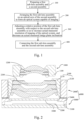
- Fig. 1 is a flow chart of a method for assembling a camera module. Referring to Fig. 1 , the method includes steps 100 to 400.
- a first sub-lens assembly and a second sub-assembly are prepared.
- Fig. 2 is a schematic diagram illustrating a first sub-lens assembly 1000, a second sub-assembly 6000 and their initial positions.
- the first sub-lens assembly 1000 includes a first lens barrel 1100 and at least one first lens 1200.
- the number of the first lenses 1200 is two. However, it should be readily understood that the number of the first lenses 1200 may also have other values, for example, one, three, or four.
- the second sub-assembly 6000 includes a second sub-lens assembly 2000 and a photosensitive assembly 3000 fixed together.
- the second sub-lens assembly 2000 includes a second lens barrel 2100 and at least one second lens 2200.
- the number of the second lenses 2200 is three. However, it should be readily understood that the number of the second lenses 2200 may also have other values, for example, one, two, or four.
- the second lens barrel 2100 of the second sub-lens assembly 2000 includes an inner lens barrel 2110 and an outer lens barrel 2120 (where the outer lens barrel 2120 may also be referred to as a lens base) nested together.
- the inner lens barrel 2110 and the outer lens barrel 2120 are threadedly connected. It should be noted that the threaded connection is not the only way for connecting the inner lens barrel 2110 and the outer lens barrel 2120.
- the second lens barrel 2100 may be an integral lens barrel.
- the photosensitive assembly 3000 includes a circuit board 3100, a photosensitive element 3200 mounted on the circuit board 3100, a tubular support 3400 fabricated on the circuit board 3100 and surrounding the photosensitive element 3200, and a filter element 3300 mounted on the support 3400.
- the tubular support 3400 has an extension portion that extends inward (toward the photosensitive element 3200) and that can serve as a lens bracket, and the filter element 3300 is mounted on the extension portion.
- the tubular support 3400 further has an upper surface, and the photosensitive assembly may be connected to other components (for example, the second sub-lens assembly 2000) of the camera module via the upper surface.
- the photosensitive assembly 3000 may be of other structures.
- the circuit board of the photosensitive assembly has a through hole, and the photosensitive element is mounted in the through hole of the circuit board.
- a supporting portion is formed around the photosensitive element by molding, and extends inward to come into contact with the photosensitive element (for example, the supporting portion covers at least one part of a non-photosensitive area that is located at an edge of the photosensitive element) .
- the photosensitive assembly may not include the filter element.
- the second sub-lens assembly 2000 and the photosensitive assembly 3000 are fixed by means of non-active alignment, to form the second sub-assembly 6000.
- the active alignment may be abbreviated as AA.
- the non-active alignment manner refers to a manner other than active alignment.
- the second sub-lens assembly 2000 and the photosensitive assembly 3000 may be fixed together by using a mechanical alignment manner, to form the second sub-assembly 6000.
- the first sub-lens assembly 1000 is arranged on an optical axis of the second sub-assembly 6000 to form an optical system capable of imaging and including the at least one first lens 1200 and the at least one second lens 2200.
- arranging the first sub-lens assembly 1000 on the optical axis of the second sub-assembly 6000 means preliminarily aligning the two, to form an optical system capable of imaging. That is to say, as long as the optical system including all the first lenses 1200 and all the second lenses 2200 is capable of imaging, it may be considered that the arrangement work in this step is complete.
- the central axes of the first lens barrel 1100 and the second lens barrel 2100 may not coincide with the optical axis after the arrangement is completed.
- a relative position of the first sub-lens assembly 1000 with respect to the second sub-lens assembly 2000 is adjusted, so as to maximize an actual measured resolution of imaging of the optical system (where when the actual measured resolution is increased to a preset threshold, it may be considered that the actual measured resolution is maximized), and minimize an actual measured image plane inclination of imaging of the optical system that is obtained by using the photosensitive element (where when the actual measured image plane inclination is decreased to a preset threshold, it may be considered that the actual measured image plane inclination is minimized).
- the adjustment of the relative position of the first sub-lens assembly 1000 and the second sub-lens assembly 2000 may be performed over multiple degrees of freedom.
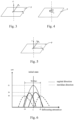
- Fig. 3 illustrates a relative position adjustment method.
- the first sub-lens assembly 1000 may be moved with respect to the second sub-lens assembly 2000 in directions x, y, and z (that is, the adjustment of relative position can be performed in three degrees of freedom).
- the direction z is a direction along the optical axis, and the directions x and y are directions perpendicular to the optical axis.
- the directions x and y are both located in an adjustment plane P, and translation in the adjustment plane P can be decomposed into two components in the directions x and y.
- Fig. 4 illustrates a rotational adjustment.
- the adjustment of relative position can be not only performed in the three degrees of freedom shown in Fig. 3 , but also performed in a rotational degree of freedom, that is, adjustment in a direction r.
- the adjustment in the direction r is rotation in the adjustment plane P, that is, rotation about an axis perpendicular to the adjustment plane P.
- Fig. 5 illustrates a relative position adjustment method further allowing for adjustment in directions v and w.
- the direction v represents an angle of rotation in the xoz plane
- the direction w represents an angle of rotation in the yoz plane
- the angles of rotation in the direction v and the direction w may form a vector angle, which represents the overall inclination state. That is to say, the inclination posture of the first sub-lens assembly with respect to the second sub-lens assembly (that is, the inclination of the optical axis of the first sub-lens assembly with respect to the optical axis of the second sub-lens assembly) may be adjusted by adjustment in the direction v and the direction w.
- Adjustment over the above-mentioned six degrees of freedom in the directions x, y, z, r, v, and w may all affect the imaging quality of the optical system (for example, the value of the resolution).
- the method for adjusting the relative position may be performed in any one of, or any two or more of the above-mentioned six degrees of freedom.
- obtaining the actual measured resolution of imaging of the optical system includes steps 301 and 302.
- step 301 a plurality of targets corresponding to a reference field of view and a test field of view is set.
- a center field of view is selected as the reference field of view, and one or more fields of view corresponding to a region of interest are selected as the test field of view (for example, 80% field of view).
- step 302 a resolution defocusing curve corresponding to each target is acquired based an image output by the photosensitive assembly. According to the resolution defocusing curve, actual measured resolution of the corresponding field of view can be obtained.
- the resolution is represented by a modulation transfer function (MTF).
- MTF modulation transfer function
- a larger MTF value indicates higher resolution.
- the MTF defocusing curve acquired based on the image output by the photosensitive assembly, the resolution of imaging of the optical system can be obtained in real time.
- the variation of the MTF defocusing curve it can be determined whether a maximum resolution has been reached currently.
- Fig. 6 illustrates MTF defocusing curves in an initial state, including an MTF defocusing curve of the center field of view and MTF defocusing curves of imaging of two targets located in the test field of view in a sagittal direction and a meridian direction.
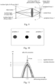
- FIG. 9 is a schematic diagram of an image plane inclination. It can be seen that in Fig. 9 , an object plane perpendicular to the optical axis forms an inclined image plane after lens imaging. Incident light of the center field of view is focused at a central focus after passing through a lens. Incident light of an off-axis field of view 1 is focused at a peripheral focus 1' after passing through the lens, where there is an axial deviation D2 between the peripheral focus 1' and the central focus. Incident light of an off-axis field of view 1' is focused at a peripheral focus 1 after passing through the lens, where there is an axial deviation D1 between the peripheral focus 1 and the central focus.
- Fig. 10 is a schematic diagram of comparison of images at the central position, the periphery 1, and the periphery 1'. It can be seen that images at the periphery 1 and the periphery 1' are obviously more blurred than the image at the central position.
- the angle of inclination between the first sub-lens assembly and the second sub-lens assembly is adjusted to compensate for the above-mentioned image plane inclination.
- acquiring the actual measured image plane inclination includes steps 303 and 304.
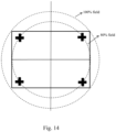
- step 303 for any test field of view (for example, 80% field of view), a plurality of targets corresponding to different test positions in the test field of view is set.
- Fig. 14 illustrates an example of a target setting method. As shown in Fig. 14 , the test field of view is 80% field of view, and four targets are respectively disposed at four corners of a chart.
- each resolution defocusing curve corresponding to different positions in a same field of view is acquired based on an image output by the photosensitive assembly.
- the resolution defocusing curves converge on the abscissa axis (the coordinate axis representing a defocusing amount along the optical axis direction)
- a position offset in the optical axis direction between peaks of resolution defocusing curves corresponding to different test positions in a test field of view are decreased to a preset threshold, it indicates that the image plane inclination corresponding to the test field of view has been compensated for.
- step 300 includes steps 310 and 320.
- step 310 the actual measured resolution of imaging of the optical system is increased to a corresponding threshold by moving the first sub-lens assembly 1000 with respect to the second sub-lens assembly 2000 in an adjustment plane P.
- the adjustment over six degrees of freedom in the directions x, y, z, r, v, and w has been described above.
- Translation in the directions x and y and rotation in the direction r may be considered to be movement in the adjustment plane P in this step.
- a plurality of targets corresponding to the reference field of view and the test field of view is set, and then a resolution defocusing curve corresponding to each target is acquired based on an image output by the photosensitive assembly.
- the first sub-lens assembly 1000 is moved with respect to the second sub-lens assembly 2000 in the directions x, y, and r, so that a peak of a resolution defocusing curve corresponding to imaging of a target in the reference field of view is increased to a corresponding threshold.
- the center field of view may be used as the reference field of view. However, it should be noted that the reference field of view is not limited to the center field of view. Other fields of view may also be selected as the reference field of view.
- increasing the actual measured resolution to a corresponding threshold is: increasing a peak of a resolution defocusing curve corresponding to imaging of a target in the reference field of view to a corresponding threshold.
- Fig. 7 illustrates an example of MTF defocusing curves after adjustment in step 310. It can be seen that after the adjustment, MTF values of imaging of the two targets in the sagittal direction and the meridian direction both increase obviously.
- Fig. 8 illustrates the first sub-lens assembly 1000, the second sub-assembly 6000 and a positional relationship thereof after adjustment in step 310. It can be seen that the central axis of the first sub-lens assembly 1000 is offset with respect to the central axis of the second sub-lens assembly 2000 in the direction x by ⁇ x. It should be noted that Fig. 8 is merely exemplary. Although no offset in the direction y is shown in Fig. 8 , it should be readily understood by those skilled in the art that the central axis of the first sub-lens assembly 1000 may also be offset with respect to the central axis of the second sub-lens assembly 2000 in the direction y by ⁇ y.
- step 320 the axis of the first sub-lens assembly 1000 is tilted with respect to the axis of the second sub-lens assembly 2000, so as to increase the actual measured resolution of imaging of the optical system in the test field of view to a corresponding threshold, and decrease the actual measured image plane inclination of imaging of the optical system in the test field of view to a corresponding threshold.
- Rotation in the directions v and w corresponds to the tilting adjustment in this step.
- increasing the actual measured resolution to a corresponding threshold includes: increasing the smallest one of peaks of resolution defocusing curves corresponding to imaging of a plurality of targets of different test positions in the test field of view to a corresponding threshold.
- Increasing the actual measured resolution to a corresponding threshold may further include: increasing uniformity of the peaks of the resolution defocusing curves corresponding to imaging of the plurality of targets of different test positions in the test field of view to a corresponding threshold.
- Increasing the uniformity of the peaks includes: decreasing a variance of the peaks of the resolution defocusing curves corresponding to imaging of the plurality of targets in the test field of view to a corresponding threshold.
- Decreasing the actual measured image plane inclination of imaging of the optical system in the test field of view to a corresponding threshold includes: making a position offset of the peak values of the resolution defocusing curves corresponding to different test positions in the test field of view along the optical axis direction reduce to the corresponding threshold.
- Fig. 11 illustrates MTF defocusing curves after adjustment in step 320.
- Fig. 12 illustrates a relative position of the first sub-lens assembly and the second sub-lens assembly after adjustment in step 320. It can be seen in Fig. 12 that, the central axis of the first sub-lens assembly is offset with respect to the central axis of the second sub-lens assembly in the direction x by ⁇ x, and the central axis of the first sub-lens assembly 1000 is also inclined with respect to the central axis of the second sub-lens assembly 2000 by ⁇ v2. Although no inclination in the direction w is shown in Fig. 12 , it should be readily understood by those skilled in the art that the axis of the photosensitive assembly 3000 may also have an angle of inclination with respect to the central axis of the second sub-lens assembly 2000 in the direction w.
- step 400 the first sub-lens assembly 1000 and the second sub-lens assembly 2000 are connected, so that the relative position of the first sub-lens assembly 1000 and the second sub-lens assembly 2000 remain unchanged.
- Fig. 13 illustrates a camera module formed after a connecting step is performed.
- the process for connecting the first sub-lens assembly and the second sub-lens assembly may be selected as required.
- the first sub-lens assembly and the second sub-lens assembly are connected by a bonding process.
- the first sub-lens assembly 1000 and the second sub-lens assembly 2000 are bonded by using an adhesive material 4000.
- the first sub-lens assembly and the second sub-lens assembly may be connected by a laser welding process.
- the first sub-lens assembly and the second sub-lens assembly may be connected by an ultrasonic welding process.
- other welding processes may also be used. It should be noted that in the present invention, the term "connection" is not limited to direct connection.
- first sub-lens assembly and the second sub-lens assembly may be connected via an intermediate member (which may be rigid).
- Such connection via an intermediate member falls within the meaning of the term "connection" as long as the relative position of (including relative distance and posture) of the first sub-lens assembly and the second sub-lens assembly (or the photosensitive assembly and the second sub-lens assembly) remain unchanged.
- the method for assembling a camera module can improve the resolution of the camera module and the capability of process index (CPK) of mass production of the camera module; can lower the requirements on the precision of various elements of the optical imaging lens assembly and module and its assembly precision, and reduce the overall costs of the optical imaging lens assembly and module.
- the method can implement a real-time adjustment of various aberrations of the camera module during the assembly process to reduce the fluctuation of the imaging quality, thereby reducing the failure rate and the production costs, and improving the imaging quality.
- step 300 may further include: matching an actual measured image plane of imaging of the optical system with a target surface by moving the first sub-lens assembly with respect to the second sub-lens assembly in the optical axis direction.
- the adjustment over six degrees of freedom in the directions x, y, z, r, v, and w has been described above. Movement in the direction z may be considered to be movement in the optical axis direction in this step.
- the expected imaging surface is referred to as the target surface.
- the target surface is a plane.
- the expected imaging surface of the optical lens assembly is also a plane. That is to say, the target surface is a plane.
- the target surface may be a convex or concave curved surface, or a corrugated curved surface.
- the target surface should also be a convex or concave curved surface; if the photosensitive surface of the photosensitive element of the camera module corresponding to the optical lens assembly is a corrugated curved surface, the target surface should also be a corrugated curved surface.
- matching the actual measured image plane with the target surface includes: obtaining an actual measured field of view curvature of the module according to the image output by the photosensitive element, and causing the actual measured field of view curvature of the module to fall within a range of +/-5 ⁇ m. This method can further improve the imaging quality of the camera module.
- targets are set in pair for the selected test field of view.
- a pair of first targets respectively located at two ends of the central position are set in a first direction
- a pair of second targets respectively located at two ends of the central position are set in a second direction.
- the test field of view is 80% field of view
- the four targets are respectively disposed at four corners of a chart.
- the lower left target and the upper right target may be used as the pair of first targets in the first direction
- the upper left target and the lower right target may be used as the pair of second targets in the second direction.
- An inclination component of the actual measured image plane of imaging of the optical system in the first direction can be identified according to an offset vector of a resolution defocusing curve of the pair of first targets in the abscissa axis direction (that is, the optical axis direction), and an inclination component of the actual measured image plane of imaging of the optical system in the second direction can be identified according to an offset vector of a resolution defocusing curve of the pair of second targets in the abscissa axis direction.
- the posture of the first sub-lens assembly with respect to the second sub-lens assembly is adjusted to change the angle of the axis of the first sub-lens assembly with respect to the axis of the second sub-lens assembly, so as to compensate for the inclination component in the first direction and the inclination component in the second direction.
- step 310 the first sub-lens assembly is moved with respect to the second sub-lens assembly within a first range in the adjustment plane.
- step 320 if the actual measured image plane inclination cannot be decreased to fall within a preset range, a readjustment step 330 is further performed until the actual measured image plane inclination is decreased to fall within the preset range.
- the readjustment step 330 includes step 331 and 332.
- step 331 the first sub-lens assembly is moved with respect to the second sub-lens assembly within a second range in the adjustment plane.
- the second range is smaller than the first range. That is to say, compared with step 310, in step 331, the relative position of the first sub-lens assembly and the second sub-lens assembly are adjusted within a small range in the adjustment plane.
- the adjustment range is small, the actual measured resolution achieved after the adjustment in step 310 can basically be maintained.
- the image plane inclination can be reduced, making it easier to compensate for the image plane inclination in step 332.
- step 332 the angle of the central axis of the first sub-lens assembly with respect to the central axis of the second sub-lens assembly is adjusted, so that an actual measured image plane inclination of imaging of the optical system, obtained by using the photosensitive element, is decreased to a corresponding threshold. If the actual measured image plane inclination cannot be decreased to fall within the preset range, the above-mentioned steps 331 and 332 are repeated until the actual measured image plane inclination is decreased to fall within the preset range.
- FIG. 15 illustrates the camera module.
- the camera module includes a first sub-lens assembly 1000 and a second sub-assembly 6000.
- the first sub-lens assembly 1000 includes a first lens barrel 1100 and at least one first lens 1200.
- the second sub-assembly 6000 includes a second sub-lens assembly 2000 and a photosensitive assembly 3000 fixed together.
- the second sub-lens assembly 2000 includes a second lens barrel 2100 and at least one second lens 2200.
- the photosensitive assembly 3000 includes a photosensitive element 3300.
- the first sub-lens assembly 1000 is arranged on an optical axis of the second sub-lens assembly 2000 to form an optical system capable of imaging and including the at least one first lens 1200 and the at least one second lens 2200.
- the first sub-lens assembly 1000 and the second sub-lens assembly 2000 are fixed together by a connecting medium 4000.
- the connecting medium 4000 is adapted to cause a central axis of the first sub-lens assembly 1000 to have an angle of inclination of smaller than 0.5° with respect to a central axis of the second sub-lens assembly 2000.
- the connecting medium 4000 is further adapted to cause the relative position of the first sub-lens assembly 1000 and the second sub-lens assembly 2000 to remain unchanged.
- the relative position cause actual measured resolution of imaging of the optical system, obtained by using the photosensitive element 3300, to be increased to a first threshold, and cause an actual measured image plane inclination of imaging of the optical system, obtained by using the photosensitive element 3300, to be decreased to a second threshold.
- the connecting medium may be an adhesive material or a bonding pad (for example, a metal sheet).
- the second connecting medium may be an adhesive material or a bonding pad (for example, a metal sheet).
- the connecting medium by which the first sub-lens assembly and the second sub-lens assembly are connected and fixed together is neither part of the first sub-lens assembly, nor part of the second sub-lens assembly.
- the connecting medium is further adapted to cause the central axis of the first sub-lens assembly to be staggered with respect to the central axis of the second sub-lens assembly by 0 to 15 ⁇ m.
- the connecting medium is further adapted to cause the first sub-lens assembly and the second sub-lens assembly to have a structural clearance therebetween.
- the first sub-lens assembly 1000 and the second sub-lens assembly 2000 both have an optical surface and a structural surface.
- the optical surface is a surface, through which effective light passes, on a lens.
- Other surfaces on the lens than the optical surface are the structural surfaces.
- Surfaces located on the lens barrel are all structural surfaces.
- the structural clearance is a clearance between structural surfaces.
- the second sub-lens assembly 2000 and the photosensitive assembly 3000 are assembled together by means of mechanical alignment, to form the second sub-assembly 6000.
- a clearance 5000 between 10 ⁇ m and 50 ⁇ m adapted for mechanical alignment exists between the second sub-lens assembly 2000 and the photosensitive assembly 3000.
- the central axis of the first sub-lens assembly 1000 may be construed as a central axis of an optical surface 1201, which is closest to the second sub-lens assembly 2000, in the first sub-lens assembly 1000; or may be construed as a central axis defined by a structural surface 1202 of the first lens 1200 that is closest to the second sub-lens assembly 2000.
- the central axis of the first sub-lens assembly 1000 may also be construed as a central axis defined by an inner side surface of the first lens barrel.
- the central axis of the second sub-lens assembly 2000 may be construed as a central axis of an optical surface 2201, which is closest to the first sub-lens assembly 1000, in the second sub-lens assembly 2000; or may be construed as a central axis defined by a structural surface 2202 of the second lens 2200 that is closest to the first sub-lens assembly 1000.
- the central axis of the second sub-lens assembly 2000 may also be construed as a central axis defined by an inner side surface of the second lens barrel.
- the present invention is particularly suitable for a miniature camera module that is applied to a smart terminal and that includes a lens assembly having a diameter of less than 10 mm.
- Outer side surfaces of the first sub-lens assembly and the second sub-lens assembly both provide a sufficient contact surface, so that a mechanical arm (or other pick-up apparatus) can pick up (for example, clamp or suck) the first sub-lens assembly and the second sub-lens assembly via the contact surface, thereby implementing the precise adjustment of the relative position of the first sub-lens assembly and the second sub-lens assembly.
- Such precise adjustment may be adjustment in six degrees of freedom.
- the adjustment step may reach the micron order or a more precise level.
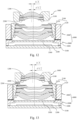
- the second sub-lens assembly 2000 may further include a motor, so as to achieve autofocusing of a camera module of a mobile phone.
- Fig. 16 illustrates an assembled camera module having a motor, where the motor is in off state.
- Fig. 17 illustrates an assembled camera module having a motor, where the motor is in on state.
- the motor includes a motor base 2310 and a motor support 2320 mounted on the motor base 2310.
- the motor support 2320 surrounds the second lens barrel 2100, and a driving structure (not shown) of the motor is mounted on the motor support 2320.
- the motor support 2320 is connected to the second lens barrel 2100 by a reed 2330.
- the second lens barrel moves along the optical axis, and the reed 2330 deforms (as shown in Fig. 17 ).
- the motor, the second lens barrel 2100, and the second lens 2200 mounted in the second lens barrel 2100 are moved and adjusted as the whole second sub-lens assembly 2000.
- the motor base 2310 and the photosensitive assembly 3000 are connected so as to achieve the connection between the second sub-lens assembly 2000 and the photosensitive assembly 3000.
- step 310 when the relative position of the first sub-lens assembly and the second sub-lens assembly are adjusted, the motor is maintained in on state (for example, the motor being electrified may be considered to indicate that the motor is started). In this way, the actual measured resolution acquired is actual measured resolution obtained when the motor is in on state.
- step 320 when the angle of inclination of the photosensitive assembly with respect to the central axis of the second sub-lens assembly is adjusted, the motor is also maintained in on state. In this way, the actual measured image plane inclination acquired is an actual measured image plane inclination obtained when the motor is in on state. After the motor is started, the reed deforms correspondingly.
- the deformation of the reed due to starting of the motor may lead to an additional inclination of the central axis of the second lens barrel with respect to the central axis of the first sub-lens assembly (referring to the angle of inclination ⁇ v4 in Fig. 17 ).
- the additional inclination of the second lens barrel caused by starting of the motor can be compensated for during the adjustment in step 310 and step 320, thereby further improving the imaging quality of the autofocus camera module.
Landscapes
- Physics & Mathematics (AREA)
- General Physics & Mathematics (AREA)
- Optics & Photonics (AREA)
- Engineering & Computer Science (AREA)
- Multimedia (AREA)
- Signal Processing (AREA)
- Health & Medical Sciences (AREA)
- Biomedical Technology (AREA)
- General Health & Medical Sciences (AREA)
- Lens Barrels (AREA)
- Studio Devices (AREA)
- Camera Bodies And Camera Details Or Accessories (AREA)
Applications Claiming Priority (2)
| Application Number | Priority Date | Filing Date | Title |
|---|---|---|---|
| CN201710814250.2A CN109495672B (zh) | 2017-09-11 | 2017-09-11 | 摄像模组及其组装方法 |
| PCT/CN2018/083923 WO2019047534A1 (zh) | 2017-09-11 | 2018-04-20 | 摄像模组及其组装方法 |
Publications (3)
| Publication Number | Publication Date |
|---|---|
| EP3684044A1 EP3684044A1 (en) | 2020-07-22 |
| EP3684044A4 EP3684044A4 (en) | 2021-04-21 |
| EP3684044B1 true EP3684044B1 (en) | 2024-10-23 |
Family
ID=65634646
Family Applications (1)
| Application Number | Title | Priority Date | Filing Date |
|---|---|---|---|
| EP18854093.4A Active EP3684044B1 (en) | 2017-09-11 | 2018-04-20 | Camera module and assembly method therefor |
Country Status (6)
| Country | Link |
|---|---|
| US (2) | US11506857B2 (https=) |
| EP (1) | EP3684044B1 (https=) |
| JP (1) | JP6953625B2 (https=) |
| KR (1) | KR102321746B1 (https=) |
| CN (2) | CN109495672B (https=) |
| WO (1) | WO2019047534A1 (https=) |
Families Citing this family (20)
| Publication number | Priority date | Publication date | Assignee | Title |
|---|---|---|---|---|
| CN109495673B (zh) * | 2017-09-11 | 2020-09-25 | 宁波舜宇光电信息有限公司 | 摄像模组及其组装方法 |
| EP3859419B1 (en) * | 2018-10-10 | 2024-05-15 | Ningbo Sunny Opotech Co., Ltd. | Optical zoom camera module and assembling method therefor |
| CN111757092B (zh) * | 2019-03-28 | 2025-03-28 | 宁波舜宇光电信息有限公司 | 摄像模组对焦组装系统和方法、镜头组件参数获取装置和感光组件参数获取装置 |
| CN111766672A (zh) * | 2019-03-30 | 2020-10-13 | 华为技术有限公司 | 一种镜头、摄像头和终端 |
| WO2020215963A1 (zh) * | 2019-04-22 | 2020-10-29 | 宁波舜宇光电信息有限公司 | 光学镜头、摄像模组及其制造方法 |
| CN112540436B (zh) * | 2019-09-04 | 2023-06-06 | 宁波舜宇光电信息有限公司 | 分体式镜头及其第一镜头部分、测试方法、组装方法和摄像模组 |
| CN110650290B (zh) * | 2019-10-12 | 2021-06-15 | 惠州市德赛自动化技术有限公司 | 一种摄像头主动对焦调整方法 |
| CN113079277B (zh) * | 2020-01-03 | 2023-05-19 | 北京小米移动软件有限公司 | 终端设备、摄像头模组及拍摄方法 |
| CN113824853B (zh) * | 2020-06-18 | 2023-04-07 | 宁波舜宇光电信息有限公司 | 摄像模组组装方法和设备 |
| CN113064248A (zh) * | 2021-03-29 | 2021-07-02 | 南昌欧菲光电技术有限公司 | 摄像头的光学对位方法、摄像头及电子设备 |
| CN115150526A (zh) * | 2021-03-31 | 2022-10-04 | 北京小米移动软件有限公司 | 镜头及移动终端 |
| CN113472983B (zh) * | 2021-06-18 | 2023-04-07 | 深圳睿晟自动化技术有限公司 | 一种摄像头模组场曲校正方法以及系统 |
| CN113483994B (zh) * | 2021-06-30 | 2022-04-26 | 湖北华鑫光电有限公司 | 一种镜头的最优组立角度的确定方法 |
| TWI783760B (zh) * | 2021-10-28 | 2022-11-11 | 新鉅科技股份有限公司 | 鏡筒及光學式辨識裝置 |
| CN116399559A (zh) * | 2021-12-28 | 2023-07-07 | 宁波舜宇光电信息有限公司 | Ar模组测试系统和方法 |
| KR20250019742A (ko) * | 2022-07-19 | 2025-02-10 | 콘티넨탈 오토노머스 모빌리티 저머니 게엠베하 | 카메라 모듈 및 카메라 모듈을 제조하는 방법 |
| WO2024034881A1 (ko) * | 2022-08-12 | 2024-02-15 | 엘지이노텍 주식회사 | 카메라 엑추에이터 및 이를 포함하는 카메라 모듈 |
| CN115720289A (zh) * | 2022-09-14 | 2023-02-28 | 蓝思科技(湘潭)有限公司深圳分公司 | 镜头、摄像头模组以及电子产品 |
| DE102023111846A1 (de) * | 2023-05-05 | 2024-11-07 | Carl Zeiss Ag | Optisches System für eine Kamera und Kamera mit einem optischen System |
| CN120321488B (zh) * | 2025-06-19 | 2025-08-12 | 宁波舜宇光电信息有限公司 | 摄像模组组装方法及摄像模组组装设备 |
Family Cites Families (21)
| Publication number | Priority date | Publication date | Assignee | Title |
|---|---|---|---|---|
| CN100370301C (zh) | 2003-12-05 | 2008-02-20 | 鸿富锦精密工业(深圳)有限公司 | 镜头模组的图像传感器与透镜组的位置调整方法 |
| JP2007121122A (ja) | 2005-10-28 | 2007-05-17 | Omron Corp | 変位センサ |
| JP4860378B2 (ja) | 2006-07-06 | 2012-01-25 | 富士フイルム株式会社 | レンズの偏芯調整方法及び装置 |
| CN101105567A (zh) * | 2006-07-11 | 2008-01-16 | 普立尔科技股份有限公司 | 镜头及调整镜头偏心的方法 |
| CN101153949B (zh) * | 2006-09-29 | 2011-07-27 | 鸿富锦精密工业(深圳)有限公司 | 相机模组及便携式电子装置 |
| CN101726986B (zh) * | 2008-10-10 | 2011-11-09 | 鸿富锦精密工业(深圳)有限公司 | 组装测试装置及方法 |
| JP2010156887A (ja) | 2008-12-29 | 2010-07-15 | Sharp Corp | レンズユニット及びこれを用いた撮像素子と電子機器 |
| JP5322722B2 (ja) * | 2009-03-26 | 2013-10-23 | 株式会社Suwaオプトロニクス | レンズ調芯装置およびレンズ調芯装置の制御方法 |
| JP5540120B2 (ja) | 2011-01-21 | 2014-07-02 | 富士フイルム株式会社 | スタック型レンズアレイ及びレンズモジュール |
| KR20160027852A (ko) | 2014-09-02 | 2016-03-10 | 삼성전기주식회사 | 렌즈의 틸트각 측정 및 보정 시스템 및 그 방법 |
| WO2016093970A1 (en) * | 2014-12-10 | 2016-06-16 | Becton, Dickinson And Company | Methods for optically aligning light collection components and optically aligned light collection systems thereof |
| CN106559615B (zh) * | 2015-09-29 | 2020-04-03 | 宁波舜宇光电信息有限公司 | 摄像模组光学防抖系统的校正设备及其校正方法 |
| CN105445885B (zh) * | 2015-10-30 | 2019-06-18 | 宁波舜宇光电信息有限公司 | 可调光学镜头和摄像模组及其制造方法 |
| CN109709747B (zh) * | 2015-12-02 | 2021-08-10 | 宁波舜宇光电信息有限公司 | 采用分体式镜头的摄像模组及其组装方法 |
| CN105487248B (zh) * | 2015-12-16 | 2018-11-23 | 宁波舜宇光电信息有限公司 | 通过调整镜片实现光学系统成像质量的补偿方法 |
| KR102167287B1 (ko) * | 2015-12-16 | 2020-10-19 | 닝보 써니 오포테크 코., 엘티디. | 렌즈의 조정에 의한 광학 시스템의 결상 품질 보상 방법 |
| CN106888344B (zh) * | 2015-12-16 | 2020-04-03 | 宁波舜宇光电信息有限公司 | 摄像模组及其像面倾斜的获取方法和调整方法 |
| CN106937107B (zh) * | 2015-12-29 | 2019-03-12 | 宁波舜宇光电信息有限公司 | 基于色差的摄像模组调焦方法 |
| US10466501B2 (en) * | 2016-05-26 | 2019-11-05 | Ams Sensors Singapore Pte. Ltd. | Optoelectronic modules including an optical system tilted with respect to a focal plane |
| CN207340018U (zh) * | 2016-11-28 | 2018-05-08 | 宁波舜宇光电信息有限公司 | 摄像模组 |
| CN107147904B (zh) * | 2017-06-08 | 2019-05-24 | Oppo广东移动通信有限公司 | 摄像头模组的测试方法、装置及及计算机可读存储介质 |
-
2017
- 2017-09-11 CN CN201710814250.2A patent/CN109495672B/zh active Active
-
2018
- 2018-04-20 EP EP18854093.4A patent/EP3684044B1/en active Active
- 2018-04-20 US US16/643,194 patent/US11506857B2/en active Active
- 2018-04-20 WO PCT/CN2018/083923 patent/WO2019047534A1/zh not_active Ceased
- 2018-04-20 CN CN201880056739.0A patent/CN111034169B/zh active Active
- 2018-04-20 JP JP2020514291A patent/JP6953625B2/ja active Active
- 2018-04-20 KR KR1020207007290A patent/KR102321746B1/ko active Active
-
2022
- 2022-08-31 US US17/900,484 patent/US11774698B2/en active Active
Also Published As
| Publication number | Publication date |
|---|---|
| US20220413251A1 (en) | 2022-12-29 |
| JP2020533636A (ja) | 2020-11-19 |
| EP3684044A4 (en) | 2021-04-21 |
| JP6953625B2 (ja) | 2021-10-27 |
| CN111034169B (zh) | 2021-09-21 |
| US11506857B2 (en) | 2022-11-22 |
| WO2019047534A1 (zh) | 2019-03-14 |
| CN109495672A (zh) | 2019-03-19 |
| KR102321746B1 (ko) | 2021-11-05 |
| US11774698B2 (en) | 2023-10-03 |
| US20200192051A1 (en) | 2020-06-18 |
| CN109495672B (zh) | 2023-06-02 |
| KR20200042493A (ko) | 2020-04-23 |
| EP3684044A1 (en) | 2020-07-22 |
| CN111034169A (zh) | 2020-04-17 |
Similar Documents
| Publication | Publication Date | Title |
|---|---|---|
| US11774698B2 (en) | Camera module and method for assembling same | |
| EP3684043B1 (en) | Camera module and assembly method therefor | |
| CN207340018U (zh) | 摄像模组 | |
| CN110320625B (zh) | 光学镜头、摄像模组及其组装方法 | |
| CN112995651B (zh) | 相机模块主动对准方法 | |
| EP3248369B1 (en) | Camera focus for adas | |
| US20220217254A1 (en) | Camera module array and assembly method therefor | |
| WO2014203676A1 (ja) | 位置決め装置、位置決め方法及び複眼カメラモジュール | |
| CN110557523B (zh) | 摄像模组阵列及其组装方法 | |
| CN110941061B (zh) | 光学镜头、摄像模组及组装方法 | |
| TWI756521B (zh) | 光學鏡頭、攝像模組及其組裝方法 | |
| US10893180B2 (en) | Imaging device | |
| EP3916456B1 (en) | Optical lens, camera module, and assembly method for the optical lens | |
| US20240159943A1 (en) | Method for manufacturing an optical module and optical module |
Legal Events
| Date | Code | Title | Description |
|---|---|---|---|
| STAA | Information on the status of an ep patent application or granted ep patent |
Free format text: STATUS: THE INTERNATIONAL PUBLICATION HAS BEEN MADE |
|
| PUAI | Public reference made under article 153(3) epc to a published international application that has entered the european phase |
Free format text: ORIGINAL CODE: 0009012 |
|
| STAA | Information on the status of an ep patent application or granted ep patent |
Free format text: STATUS: REQUEST FOR EXAMINATION WAS MADE |
|
| 17P | Request for examination filed |
Effective date: 20200313 |
|
| AK | Designated contracting states |
Kind code of ref document: A1 Designated state(s): AL AT BE BG CH CY CZ DE DK EE ES FI FR GB GR HR HU IE IS IT LI LT LU LV MC MK MT NL NO PL PT RO RS SE SI SK SM TR |
|
| AX | Request for extension of the european patent |
Extension state: BA ME |
|
| DAV | Request for validation of the european patent (deleted) | ||
| DAX | Request for extension of the european patent (deleted) | ||
| A4 | Supplementary search report drawn up and despatched |
Effective date: 20210324 |
|
| RIC1 | Information provided on ipc code assigned before grant |
Ipc: H04N 5/225 20060101AFI20210318BHEP Ipc: G02B 7/08 20210101ALI20210318BHEP Ipc: H04N 17/00 20060101ALI20210318BHEP Ipc: G02B 7/00 20210101ALI20210318BHEP Ipc: G02B 13/00 20060101ALI20210318BHEP |
|
| STAA | Information on the status of an ep patent application or granted ep patent |
Free format text: STATUS: EXAMINATION IS IN PROGRESS |
|
| 17Q | First examination report despatched |
Effective date: 20230208 |
|
| P01 | Opt-out of the competence of the unified patent court (upc) registered |
Effective date: 20230523 |
|
| REG | Reference to a national code |
Ref legal event code: R079 Free format text: PREVIOUS MAIN CLASS: H04N0005225000 Ref country code: DE Ref legal event code: R079 Ref document number: 602018075825 Country of ref document: DE Free format text: PREVIOUS MAIN CLASS: H04N0005225000 Ipc: H04N0023000000 |
|
| GRAJ | Information related to disapproval of communication of intention to grant by the applicant or resumption of examination proceedings by the epo deleted |
Free format text: ORIGINAL CODE: EPIDOSDIGR1 |
|
| GRAP | Despatch of communication of intention to grant a patent |
Free format text: ORIGINAL CODE: EPIDOSNIGR1 |
|
| GRAP | Despatch of communication of intention to grant a patent |
Free format text: ORIGINAL CODE: EPIDOSNIGR1 |
|
| STAA | Information on the status of an ep patent application or granted ep patent |
Free format text: STATUS: GRANT OF PATENT IS INTENDED |
|
| RIC1 | Information provided on ipc code assigned before grant |
Ipc: H04N 23/55 20230101ALI20240415BHEP Ipc: H04N 23/54 20230101ALI20240415BHEP Ipc: H04N 17/00 20060101ALI20240415BHEP Ipc: G02B 13/00 20060101ALI20240415BHEP Ipc: G02B 7/02 20060101ALI20240415BHEP Ipc: G02B 7/08 20060101ALI20240415BHEP Ipc: H04N 23/00 20230101AFI20240415BHEP |
|
| RIN1 | Information on inventor provided before grant (corrected) |
Inventor name: CHU, SHUIJIA Inventor name: WANG, YIQI Inventor name: LIU, CHUNMEI Inventor name: LIAO, HAILONG Inventor name: WANG, MINGZHU |
|
| INTG | Intention to grant announced |
Effective date: 20240517 |
|
| GRAS | Grant fee paid |
Free format text: ORIGINAL CODE: EPIDOSNIGR3 |
|
| GRAA | (expected) grant |
Free format text: ORIGINAL CODE: 0009210 |
|
| STAA | Information on the status of an ep patent application or granted ep patent |
Free format text: STATUS: THE PATENT HAS BEEN GRANTED |
|
| AK | Designated contracting states |
Kind code of ref document: B1 Designated state(s): AL AT BE BG CH CY CZ DE DK EE ES FI FR GB GR HR HU IE IS IT LI LT LU LV MC MK MT NL NO PL PT RO RS SE SI SK SM TR |
|
| REG | Reference to a national code |
Ref country code: GB Ref legal event code: FG4D |
|
| REG | Reference to a national code |
Ref country code: CH Ref legal event code: EP |
|
| REG | Reference to a national code |
Ref country code: DE Ref legal event code: R096 Ref document number: 602018075825 Country of ref document: DE |
|
| REG | Reference to a national code |
Ref country code: IE Ref legal event code: FG4D |
|
| REG | Reference to a national code |
Ref country code: LT Ref legal event code: MG9D |
|
| REG | Reference to a national code |
Ref country code: NL Ref legal event code: MP Effective date: 20241023 |
|
| REG | Reference to a national code |
Ref country code: AT Ref legal event code: MK05 Ref document number: 1735815 Country of ref document: AT Kind code of ref document: T Effective date: 20241023 |
|
| PG25 | Lapsed in a contracting state [announced via postgrant information from national office to epo] |
Ref country code: NL Free format text: LAPSE BECAUSE OF FAILURE TO SUBMIT A TRANSLATION OF THE DESCRIPTION OR TO PAY THE FEE WITHIN THE PRESCRIBED TIME-LIMIT Effective date: 20241023 |
|
| PG25 | Lapsed in a contracting state [announced via postgrant information from national office to epo] |
Ref country code: NL Free format text: LAPSE BECAUSE OF FAILURE TO SUBMIT A TRANSLATION OF THE DESCRIPTION OR TO PAY THE FEE WITHIN THE PRESCRIBED TIME-LIMIT Effective date: 20241023 |
|
| PG25 | Lapsed in a contracting state [announced via postgrant information from national office to epo] |
Ref country code: PT Free format text: LAPSE BECAUSE OF FAILURE TO SUBMIT A TRANSLATION OF THE DESCRIPTION OR TO PAY THE FEE WITHIN THE PRESCRIBED TIME-LIMIT Effective date: 20250224 Ref country code: HR Free format text: LAPSE BECAUSE OF FAILURE TO SUBMIT A TRANSLATION OF THE DESCRIPTION OR TO PAY THE FEE WITHIN THE PRESCRIBED TIME-LIMIT Effective date: 20241023 Ref country code: IS Free format text: LAPSE BECAUSE OF FAILURE TO SUBMIT A TRANSLATION OF THE DESCRIPTION OR TO PAY THE FEE WITHIN THE PRESCRIBED TIME-LIMIT Effective date: 20250223 |
|
| PG25 | Lapsed in a contracting state [announced via postgrant information from national office to epo] |
Ref country code: FI Free format text: LAPSE BECAUSE OF FAILURE TO SUBMIT A TRANSLATION OF THE DESCRIPTION OR TO PAY THE FEE WITHIN THE PRESCRIBED TIME-LIMIT Effective date: 20241023 |
|
| PG25 | Lapsed in a contracting state [announced via postgrant information from national office to epo] |
Ref country code: BG Free format text: LAPSE BECAUSE OF FAILURE TO SUBMIT A TRANSLATION OF THE DESCRIPTION OR TO PAY THE FEE WITHIN THE PRESCRIBED TIME-LIMIT Effective date: 20241023 |
|
| PG25 | Lapsed in a contracting state [announced via postgrant information from national office to epo] |
Ref country code: ES Free format text: LAPSE BECAUSE OF FAILURE TO SUBMIT A TRANSLATION OF THE DESCRIPTION OR TO PAY THE FEE WITHIN THE PRESCRIBED TIME-LIMIT Effective date: 20241023 |
|
| PG25 | Lapsed in a contracting state [announced via postgrant information from national office to epo] |
Ref country code: NO Free format text: LAPSE BECAUSE OF FAILURE TO SUBMIT A TRANSLATION OF THE DESCRIPTION OR TO PAY THE FEE WITHIN THE PRESCRIBED TIME-LIMIT Effective date: 20250123 |
|
| PG25 | Lapsed in a contracting state [announced via postgrant information from national office to epo] |
Ref country code: LV Free format text: LAPSE BECAUSE OF FAILURE TO SUBMIT A TRANSLATION OF THE DESCRIPTION OR TO PAY THE FEE WITHIN THE PRESCRIBED TIME-LIMIT Effective date: 20241023 Ref country code: GR Free format text: LAPSE BECAUSE OF FAILURE TO SUBMIT A TRANSLATION OF THE DESCRIPTION OR TO PAY THE FEE WITHIN THE PRESCRIBED TIME-LIMIT Effective date: 20250124 Ref country code: AT Free format text: LAPSE BECAUSE OF FAILURE TO SUBMIT A TRANSLATION OF THE DESCRIPTION OR TO PAY THE FEE WITHIN THE PRESCRIBED TIME-LIMIT Effective date: 20241023 |
|
| PG25 | Lapsed in a contracting state [announced via postgrant information from national office to epo] |
Ref country code: PL Free format text: LAPSE BECAUSE OF FAILURE TO SUBMIT A TRANSLATION OF THE DESCRIPTION OR TO PAY THE FEE WITHIN THE PRESCRIBED TIME-LIMIT Effective date: 20241023 |
|
| PG25 | Lapsed in a contracting state [announced via postgrant information from national office to epo] |
Ref country code: RS Free format text: LAPSE BECAUSE OF FAILURE TO SUBMIT A TRANSLATION OF THE DESCRIPTION OR TO PAY THE FEE WITHIN THE PRESCRIBED TIME-LIMIT Effective date: 20250123 |
|
| PG25 | Lapsed in a contracting state [announced via postgrant information from national office to epo] |
Ref country code: SM Free format text: LAPSE BECAUSE OF FAILURE TO SUBMIT A TRANSLATION OF THE DESCRIPTION OR TO PAY THE FEE WITHIN THE PRESCRIBED TIME-LIMIT Effective date: 20241023 |
|
| PGFP | Annual fee paid to national office [announced via postgrant information from national office to epo] |
Ref country code: DE Payment date: 20250225 Year of fee payment: 8 |
|
| PG25 | Lapsed in a contracting state [announced via postgrant information from national office to epo] |
Ref country code: DK Free format text: LAPSE BECAUSE OF FAILURE TO SUBMIT A TRANSLATION OF THE DESCRIPTION OR TO PAY THE FEE WITHIN THE PRESCRIBED TIME-LIMIT Effective date: 20241023 |
|
| PG25 | Lapsed in a contracting state [announced via postgrant information from national office to epo] |
Ref country code: EE Free format text: LAPSE BECAUSE OF FAILURE TO SUBMIT A TRANSLATION OF THE DESCRIPTION OR TO PAY THE FEE WITHIN THE PRESCRIBED TIME-LIMIT Effective date: 20241023 |
|
| PG25 | Lapsed in a contracting state [announced via postgrant information from national office to epo] |
Ref country code: RO Free format text: LAPSE BECAUSE OF FAILURE TO SUBMIT A TRANSLATION OF THE DESCRIPTION OR TO PAY THE FEE WITHIN THE PRESCRIBED TIME-LIMIT Effective date: 20241023 |
|
| REG | Reference to a national code |
Ref country code: DE Ref legal event code: R097 Ref document number: 602018075825 Country of ref document: DE |
|
| PG25 | Lapsed in a contracting state [announced via postgrant information from national office to epo] |
Ref country code: SK Free format text: LAPSE BECAUSE OF FAILURE TO SUBMIT A TRANSLATION OF THE DESCRIPTION OR TO PAY THE FEE WITHIN THE PRESCRIBED TIME-LIMIT Effective date: 20241023 |
|
| PG25 | Lapsed in a contracting state [announced via postgrant information from national office to epo] |
Ref country code: CZ Free format text: LAPSE BECAUSE OF FAILURE TO SUBMIT A TRANSLATION OF THE DESCRIPTION OR TO PAY THE FEE WITHIN THE PRESCRIBED TIME-LIMIT Effective date: 20241023 |
|
| PG25 | Lapsed in a contracting state [announced via postgrant information from national office to epo] |
Ref country code: IT Free format text: LAPSE BECAUSE OF FAILURE TO SUBMIT A TRANSLATION OF THE DESCRIPTION OR TO PAY THE FEE WITHIN THE PRESCRIBED TIME-LIMIT Effective date: 20241023 |
|
| PLBE | No opposition filed within time limit |
Free format text: ORIGINAL CODE: 0009261 |
|
| STAA | Information on the status of an ep patent application or granted ep patent |
Free format text: STATUS: NO OPPOSITION FILED WITHIN TIME LIMIT |
|
| PG25 | Lapsed in a contracting state [announced via postgrant information from national office to epo] |
Ref country code: SE Free format text: LAPSE BECAUSE OF FAILURE TO SUBMIT A TRANSLATION OF THE DESCRIPTION OR TO PAY THE FEE WITHIN THE PRESCRIBED TIME-LIMIT Effective date: 20241023 |
|
| 26N | No opposition filed |
Effective date: 20250724 |
|
| REG | Reference to a national code |
Ref country code: CH Ref legal event code: H13 Free format text: ST27 STATUS EVENT CODE: U-0-0-H10-H13 (AS PROVIDED BY THE NATIONAL OFFICE) Effective date: 20251125 |
|
| PG25 | Lapsed in a contracting state [announced via postgrant information from national office to epo] |
Ref country code: LU Free format text: LAPSE BECAUSE OF NON-PAYMENT OF DUE FEES Effective date: 20250420 |
|
| PG25 | Lapsed in a contracting state [announced via postgrant information from national office to epo] |
Ref country code: MC Free format text: LAPSE BECAUSE OF FAILURE TO SUBMIT A TRANSLATION OF THE DESCRIPTION OR TO PAY THE FEE WITHIN THE PRESCRIBED TIME-LIMIT Effective date: 20241023 |
|
| REG | Reference to a national code |
Ref country code: BE Ref legal event code: MM Effective date: 20250430 |
|
| PG25 | Lapsed in a contracting state [announced via postgrant information from national office to epo] |
Ref country code: BE Free format text: LAPSE BECAUSE OF NON-PAYMENT OF DUE FEES Effective date: 20250430 |
|
| PG25 | Lapsed in a contracting state [announced via postgrant information from national office to epo] |
Ref country code: CH Free format text: LAPSE BECAUSE OF NON-PAYMENT OF DUE FEES Effective date: 20250430 |
|
| PGFP | Annual fee paid to national office [announced via postgrant information from national office to epo] |
Ref country code: GB Payment date: 20260303 Year of fee payment: 9 |
|
| PG25 | Lapsed in a contracting state [announced via postgrant information from national office to epo] |
Ref country code: IE Free format text: LAPSE BECAUSE OF NON-PAYMENT OF DUE FEES Effective date: 20250420 |
|
| PGFP | Annual fee paid to national office [announced via postgrant information from national office to epo] |
Ref country code: FR Payment date: 20260209 Year of fee payment: 9 |