EP3682956B1 - Spielzeug - Google Patents
Spielzeug Download PDFInfo
- Publication number
- EP3682956B1 EP3682956B1 EP19209755.8A EP19209755A EP3682956B1 EP 3682956 B1 EP3682956 B1 EP 3682956B1 EP 19209755 A EP19209755 A EP 19209755A EP 3682956 B1 EP3682956 B1 EP 3682956B1
- Authority
- EP
- European Patent Office
- Prior art keywords
- product carrier
- lever
- toy
- carry
- along
- Prior art date
- Legal status (The legal status is an assumption and is not a legal conclusion. Google has not performed a legal analysis and makes no representation as to the accuracy of the status listed.)
- Active
Links
Images




Classifications
-
- A—HUMAN NECESSITIES
- A63—SPORTS; GAMES; AMUSEMENTS
- A63H—TOYS, e.g. TOPS, DOLLS, HOOPS OR BUILDING BLOCKS
- A63H17/00—Toy vehicles, e.g. with self-drive; ; Cranes, winches or the like; Accessories therefor
- A63H17/05—Trucks; Lorries
-
- A—HUMAN NECESSITIES
- A63—SPORTS; GAMES; AMUSEMENTS
- A63H—TOYS, e.g. TOPS, DOLLS, HOOPS OR BUILDING BLOCKS
- A63H17/00—Toy vehicles, e.g. with self-drive; ; Cranes, winches or the like; Accessories therefor
- A63H17/05—Trucks; Lorries
- A63H2017/055—Trucks; Lorries for agricultural use
Definitions
- the invention relates to a toy with a product carrier which can be displaced relative to a toy frame and which is accommodated in a storage position in a chamber.
- Toys with movable components, which in turn carry other components, which are accommodated in a chamber with a movable hood in at least one relative position of the toy, are known from the market.
- the EP 1 060 773 A2 discloses a toy trailer in the form of a hay bagger.
- the US 2014/0378026 A1 discloses a toy vehicle in the form of a recycling truck.
- the DE 20 2011 050 081 U1 discloses a toy vehicle in the form of a toy truck.
- the EP 3 195 913 A1 apparently a toy cattle trailer.
- a realistic opening / closing movement of the hood for the chamber of the toy can be achieved by using a driver lever that is carried along by the product carrier.
- the design of the driver lever together with the driver function via the product carrier represents a reversible shift the hood between the closed position and the open position when the product carrier is moved from the storage position to the extended position.
- Exactly one driver lever can be used. Alternatively, several driver levers can also be used.
- the toy can be a toy vehicle.
- the toy can be a trailer for a towing vehicle.
- the toy can be designed as an agricultural machine, in particular as a pressing / wrapping machine for round bales, namely for straw bales.
- the toy can be made entirely of plastic.
- the components of the toy can be injection molded parts.
- the hood initially remains in an open position regardless of a further displacement movement of the product carrier after the hood has been moved into the open position by the driver lever. This ensures a realistic game situation.
- the open position can be the open position or an intermediate position between the closed position and the open position.
- An arrangement of the driver lever according to claim 3 avoids that the driver lever and the product interfere with the displacement of the product carrier or with the displacement of the hood of the chamber.
- a drive device for moving the product carrier according to claim 4 is operationally reliable and can be manufactured inexpensively.
- An embodiment of the tape actuation unit according to claim 5 as a rotary knob ensures an intuitively tangible gaming experience.
- a guide rail according to claim 6 enables a safe displacement guidance of the product carrier.
- the guide rail can be designed as a guide link, so that in particular an undesired lifting of the product carrier from the toy frame is prevented.
- a driver cylinder according to claim 7 ensures that the driver lever rests securely on the product carrier, particularly when the driver lever is taken along from the product carrier when the product carrier is extended from the storage position to the extended position.
- a return driver section on the product carrier according to claim 8 ensures that the driver lever is safely carried along when the product carrier is returned from the extended position into the storage position.
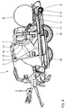
- the Figures 1 to 7 show a toy 1 in the form of a toy vehicle trailer, which is designed as a round bale press / wrap combination.
- the toy 1 is modeled on a machine used in agriculture.
- straw is first pressed into a round bale within a chamber, which corresponds to chamber 2 of toy 1, and then pulled out of the chamber and wrapped in a wrapping station of the machine.
- Components of the toy 1 are modeled on these "pressing” and “winding” processes in terms of toy technology, without actually exercising these functions of the real agricultural machine.
- the toy 1 has a toy frame 3 on which movable add-on components are attached to the toy 1.
- a product carrier 4 in the form of a slide is movably connected to the toy frame 3.
- the carriage 4 has a cylindrically concavely curved receiving surface 5 for carrying a round bale 6 simulated in the toy 1 made of plastic.
- Chamber 2 is in the Fig. 1 bounded by a hood 7 to the right, to the top, and to the side facing the viewer and to the side facing away from the viewer.
- the hood 7 is pivotable about a swivel joint 8 on the toy frame 3 displaceable between one in the Fig. 1 shown closed position in which the chamber 2 is closed by the hood 7 and an open position.
- a guide rail 12 is used, which in the embodiment shown is designed as a guide link for a foot section of the product carrier 4.
- the guide rail 12 is fixed connected to the toy frame 3 and can be an integral part of this.
- the guide rail 12 is bent forward and downward in the area of the fully extended extended position of the product carrier 4, so that the product carrier 4 is in the extended position (cf. Fig. 5 ) for dispensing the round bale 6 is pivoted about a pivot axis which corresponds approximately to an axis of rotation of the rotary knob 11.
- a driver lever 13 is pivotably connected to the hood 7 about a further pivot joint 14. Seen in a transverse extension of the product carrier 4 perpendicular to the plane of the drawing Figures 1 to 7 the driver lever 13 is arranged on one side of the product carrier 4. Between the pivot joint 14 and a free end, the driver lever 13 is curved in an approximately sickle-shaped part-circle shape, with two short straight sections of the driver lever at a partial circle section 15 of the driver lever 13 towards the pivot joint 14 on the one hand and towards the free end on the other hand, compared to the pitch circle section 15 13 connect. At the free end of the driver lever 13 has a molded driver cylinder 16 with horizontal and transverse to the displacement direction of the product carrier 4, ie perpendicular to the plane of the drawing Figures 1 to 7 running cylinder axis.
- a lever starting position of the driver lever 13 which is in the Fig. 1 is shown, the hood 7 is in the closed position.
- the driver cylinder 16 of the driver lever 13 is received in a driver receptacle 17 of the product carrier 4.
- the driver receptacle 17 is spaced apart from the receiving surface 5 of the product carrier 4 and lies in the Figures 1 to 7 to the left of the receiving surface 5.
- the driver lever 13 is carried along when the product carrier 4 is extended from the storage position into the extended position by the product carrier 4, namely by the driver receptacle 17. With this entrainment, the driver lever 13 shifts the hood 7 from the closed position to the open position (cf. Fig. 2 ), so that the product carrier 4 with the round bale 6 can move out of the chamber 2 without the round bale 6 colliding with the hood 7.
- the driver lever 13 When the product carrier 4 is extended further in the direction of the fully extended position, the driver lever 13 is released from the driver receptacle 17 of the product carrier 4 (cf. Fig. 4 ). In this released position, the driver lever 13 is supported on the toy frame 3 in such a way that the driver lever 13 moves the hood 7 to an open position (cf. Figures 4 to 6 ) holds.
- a section 18 of the driver receptacle 17 of the product carrier 4 leading in the displacement direction of the product carrier 4 between the extended position and the accommodation position is designed as a return driver section.
- This return driver section 18 comes into contact with the straight section of the driver lever 13 in the area of its free end when the product carrier 4 is returned to the storage position (cf. Fig. 6 ) and guides the driver lever 13 when the product carrier 4 is further displaced towards the storage position in the driver lever starting position back as from the sequence of the Fig. 6 and 7th with comparison of the position after Fig. 1 becomes clear.
- the result is a realistic opening and closing of the hood 7 in connection with a game operating sequence of the toy 1.
Landscapes
- Toys (AREA)
Description
- Die vorliegende Patentanmeldung nimmt die Priorität der deutschen Patentanmeldung
DE 10 2019 200 395.8 in Anspruch, deren Inhalt durch Bezugnahme hierin aufgenommen wird. - Die Erfindung betrifft ein Spielzeug mit einem relativ zu einem Spielzeugrahmen verlagerbaren Produktträger, der in einer Unterbringungsstellung in einer Kammer untergebracht ist.
- Spielzeuge mit beweglichen Komponenten, die wiederum andere Komponenten tragen, die zumindest in einer Relativstellung des Spielzeugs in einer Kammer mit beweglicher Haube untergebracht sind, sind vom Markt her bekannt. Die
EP 1 060 773 A2 offenbart einen Spielzeug-Anhänger in Form eines Heuaufnahme- und Paketiergeräts. DieUS 2014/0378026 A1 offenbart ein Spielfahrzeug in Form eines Recyclingtrucks. DieDE 20 2011 050 081 U1 offenbart ein Spielfahrzeug in Form eines Spielzeug-Lastwagens. DieEP 3 195 913 A1 offenbar einen Spielzeug-Viehtransportanhänger. - Es ist eine Aufgabe der vorliegenden Erfindung, insbesondere im Zusammenhang mit der Ausgestaltung eines Spielzeugs als landwirtschaftliche Maschine, z.B. in Form einer Rundballen-Press/Wickel-Kombination, das Öffnen einer Haube einer Kammer, in der ein Produktträger ggf. mitsamt Produkt in einer Unterbringungsstellung untergebracht ist, beim Verlagern des Produktträgers aus der Unterbringungsstellung in eine Ausfahrstellung möglichst realitätsnah zu gestalten.
- Diese Aufgabe ist erfindungsgemäß gelöst, durch ein Spielzeug mit den im Anspruch 1 angegebenen Merkmalen.
- Erfindungsgemäß wurde erkannt, dass eine realitätsnahe Öffnungs-/Schließbewegung der Haube für die Kammer des Spielzeugs durch Einsatz eines Mitnehmerhebels erreicht werden kann, der vom Produktträger mitgenommen wird. Die Gestaltung des Mitnehmerhebels zusammen mit der Mitnahmefunktion über den Produktträger stellt eine reversible Verlagerung der Haube zwischen der Schließstellung und der Offenstellung bei Verlagerung des Produktträgers von der Unterbringungsstellung in die Ausfahrstellung sicher. Es kann genau ein Mitnehmerhebel zum Einsatz kommen. Alternativ können auch mehrere Mitnehmerhebel zum Einsatz kommen.
- Bei dem Spielzeug kann es sich um ein Spielfahrzeug handeln. Bei dem Spielzeug kann es sich um einen Anhänger für ein Zugfahrzeug handeln. Das Spielzeug kann als landwirtschaftliche Maschine, insbesondere als Press/Wickelmaschine für Rundballen, nämlich für Strohballen, ausgeführt sein. Das Spielzeug kann insgesamt aus Kunststoff gefertigt sein. Bei den Komponenten des Spielzeugs kann es sich um Spritzgussteile handeln.
- Bei einer Ausführung des Mitnehmerhebels nach Anspruch 2 bleibt die Haube unabhängig von einer weiteren Verlagerungsbewegung des Produktträgers, nachdem die Haube vom Mitnehmerhebel in die Offenstellung überführt wurde, zunächst in einer geöffneten Stellung. Dies sorgt für eine realitätsnahe Spielsituation. Bei der geöffneten Stellung kann es sich um die Offenstellung handeln oder um eine Zwischenstellung zwischen der Schließstellung und der Offenstellung.
- Eine Anordnung des Mitnehmerhebels nach Anspruch 3 vermeidet, dass sich der Mitnehmerhebel und das Produkt bei der Verlagerung des Produktträgers bzw. bei der Verlagerung der Haube der Kammer stören.
- Eine Antriebseinrichtung zur Produktträger-Verlagerung nach Anspruch 4 ist betriebssicher und lässt sich kostengünstig herstellen.
- Eine Ausführung der Band-Betätigungseinheit nach Anspruch 5 als Drehknopf sorgt für ein intuitiv erfahrbares Spielerlebnis.
- Eine Führungsschiene nach Anspruch 6 ermöglicht eine sichere Verlagerungsführung des Produktträgers. Die Führungsschiene kann als Führungskulisse ausgeführt sein, sodass insbesondere ein unerwünschtes Abheben des Produktträgers vom Spielzeugrahmen verhindert ist.
- Ein Mitnehmerzylinder nach Anspruch 7 sorgt für eine sichere Anlage des Mitnehmerhebels am Produktträger, besonders beim Mitnehmen des Mitnehmerhebels vom Produktträger beim Ausfahren des Produktträgers von Unterbringungsstellung in die Ausfahrstellung.
- Ein Rückführ-Mitnehmerabschnitt am Produktträger nach Anspruch 8 sorgt für ein sicheres Mitnehmen des Mitnehmerhebels beim Rückführen des Produktträgers von der Ausfahrstellung in die Unterbringungsstellung.
- Ein Ausführungsbeispiel der Erfindung wird nachfolgend anhand der Zeichnung näher erläutert. In dieser zeigen:
- Fig. 1
- In einem axialen Längsschnitt ein Spielzeug in Form eines Spielfahrzeug-Anhängers, ausgebildet als Rundballen-Press/Wickel-Kombination, in einer Momentanstellung mit einer Haube für eine Kammer des Spielzeugs in einer Schließstellung und einem Produktträger für einen schematisch als geschnittenen Hohlzylinder angedeuteten StrohRundballen in einer in der Kammer untergebrachten Unterbringungsstellung wobei zudem ein Mitnehmerhebel, der mit der Haube schwenkbar verbunden ist, in einer Hebel-Ausgangsstellung vorliegt;
- Fig. 2
- das Spielzeug in einer in einer Spielsequenz nachfolgenden Momentanstellung, bei der die Kammer in eine Offenstellung verlagert und der Produktträger während einer Verlagerung zwischen der Unterbringungsstellung und einer aus der Kammer ausgefahrenen Ausfahrstellung gezeigt ist;
- Fig. 3
- wiederum in der Spielsequenz nachfolgend eine Momentanstellung mit dem Produktträger in einer ausgefahrenen Stellung, kurz bevor der Mitnehmerhebel vom Produktträger freikommt;
- Fig. 4
- das Spielzeug in einer in der Spielsequenz nachfolgenden Momentanstellung mit dem Produktträger in einer weiter ausgefahrenen Stellung, wobei der Mitnehmerhebel vom Produktträger freigekommen ist und die Haube in einer von der Schließstellung abgehobenen, geöffneten Stellung hält;
- Fig. 5
- das Spielzeug in einer in der Spielsequenz nachfolgenden Momentanstellung mit dem Produktträger in komplett ausgefahrener Ausfahrstellung kurz vor dem Abgeben des Rundballens;
- Fig. 6
- das Spielfahrzeug in einer in der Spielsequenz nachfolgenden Momentanstellung nach dem Abgeben des Rundballens mit von der Ausfahrstellung in Richtung der Unterbringungsstellung zurückgefahrenem, leerem Produktträger, wobei ein führender Abschnitt einer Mitnehmeraufnahme des Produktträgers gerade in Kontakt mit dem Mitnehmerhebel zum Rückführen von diesem in die Ausgangsstellung gekommen ist; und
- Fig. 7
- das Spielzeug im weiteren Gang der Spielsequenz beim weiteren Rückführen des Produktträgers in die Unterbringungsstellung, wobei der Rückführ-Mitnehmerabschnitt des Produktträgers die Mitnehmerhebel weiter zum Rückführen in dessen Ausgangsstellung mitnimmt.
- Die
Figuren 1 bis 7 zeigen ein Spielzeug 1 in Form eines Spielfahrzeug-Anhängers, der als Rundballen-Press/Wickel-Kombination ausgeführt ist. - Das Spielzeug 1 ist einer in der Landwirtschaft genutzten Maschine nachgebildet. Bei der realen landwirtschaftlichen Maschine wird Stroh zunächst zu einem Rundballen innerhalb einer Kammer, die der Kammer 2 des Spielzeugs 1 entspricht, gepresst wird und anschließend aus der Kammer ausgefahren und in einer Wickelstation der Maschine gewickelt wird. Komponenten des Spielzeugs 1 sind diesen Vorgängen "Pressen" und "Wickeln" spielzeugtechnisch nachgebildet, ohne diese Funktionen der realen landwirtschaftlichen Maschine tatsächlich auszuüben.
- Das Spielzeug 1 hat einen Spielzeugrahmen 3, an dem bewegliche Anbaukomponenten am Spielzeug 1 angebracht sind. Mit dem Spielzeugrahmen 3 ist ein Produktträger 4 in Form eines Schlittens verlagerbar verbunden. Der Schlitten 4 hat eine zylindrisch konkav gewölbte Aufnahmefläche 5 zum Tragen eines beim Spielzeug 1 aus Kunststoff nachgebildeten Rundballens 6.
- In einer Unterbringungsstellung des Produktträgers 4, die in der
Fig. 1 dargestellt ist, ist der Produktträger 4 mitsamt dem Rundballen 6 in der Kammer 2 untergebracht. Die Kammer 2 ist in derFig. 1 nach rechts, nach oben, sowie zur dem Betrachter zugewandten Seite und zur vom Betrachter abgewandten Seite durch eine Haube 7 begrenzt. Die Haube 7 ist um ein Schwenkgelenk 8 schwenkbar am Spielzeugrahmen 3 verlagerbar zwischen einer in derFig. 1 dargestellten Schließstellung, in der die Kammer 2 von der Haube 7 verschlossen ist und einer Offenstellung. - In der Offenstellung, die in der
Fig. 2 dargestellt ist, ist die Haube 7 soweit abgehoben, dass der Produktträger 4 mitsamt dem Rundballen 6 geführt relativ zum Spielzeugrahmen 3 zwischen der Unterbringungsstellung und einer in derFig. 5 gezeigten, komplett ausgefahrenen Ausfahrstellung verlagerbar ist, in der der Produktträger 4 aus der Kammer 2 zum Abgeben des Rundballens 6 ausgefahren ist. Diese Verlagerungsbewegung des Produktträgers 4 zwischen der Unterbringungsstellung und der Ausfahrstellung ist angetrieben durch eine Antriebseinrichtung 9, die ein umlaufendes Antriebsband 10 und eine Band-Betätigungseinheit 11 aufweist, die als Drehknopf zur manuellen Betätigung ausgeführt ist. Einander benachbarte freie Enden des Antriebsbandes 10 sind fest mit dem Produktträger 4 verbunden, sodass bei einer über den Drehknopf 11 hervorgerufener UmlaufBewegung des Antriebsbandes 10 der Produktträger 4 zur Verlagerung zwischen der Unterbringungsstellung und der Ausfahrstellung mitgenommen wird. - Zur Führung der Verlagerung des Produktträgers 4 zwischen der Unterbringungsstellung und der Ausfahrstellung dient eine Führungsschiene 12, die bei der gezeigten Ausführung als Führungskulisse für einen Fußabschnitt des Produktträgers 4 ausgeführt ist. Die Führungsschiene 12 ist fest mit dem Spielzeugrahmen 3 verbunden und kann ein integraler Bestandteil von diesem sein. Die Führungsschiene 12 ist im Bereich der vollständig ausgefahrenen Ausfahrstellung des Produktträgers 4 nach vorne unten hin abgekröpft, sodass der Produktträger 4 in der Ausfahrstellung (vgl.
Fig. 5 ) zur Abgabe des Rundballens 6 um eine Schwenkachse, die in etwa einer Drehachse des Drehknopfes 11 entspricht, verschwenkt ist. - Ein Mitnehmerhebel 13 ist mit der Haube 7 um ein weiteres Schwenkgelenk 14 schwenkbar verbunden. Gesehen in einer Quererstreckung des Produktträgers 4 senkrecht zur Zeichenebene der
Fig. 1 bis 7 ist der Mitnehmerhebel 13 an einer Seite des Produktträgers 4 angeordnet. Zwischen dem Schwenkgelenk 14 und einem freien Ende ist der Mitnehmerhebel 13 in etwa sichelförmig teilkreisförmig gekrümmt ausgeführt, wobei sich an einen Teilkreisabschnitt 15 des Mitnehmerhebels 13 hin zum Schwenkgelenk 14 einerseits und hin zum freien Ende andererseits zwei im Vergleich zum Teilkreisabschnitt 15 kurze gerade Abschnitte des Mitnehmerhebels 13 anschließen. Am freien Ende hat der Mitnehmerhebel 13 einen angeformten Mitnehmerzylinder 16 mit horizontaler und quer zur Verlagerungsrichtung des Produktträgers 4 verlaufender, also senkrecht zur Zeichenebene derFig. 1 bis 7 verlaufender Zylinderachse. - In einer Hebel-Ausgangsstellung des Mitnehmerhebels 13, die in der
Fig. 1 dargestellt ist, liegt die Haube 7 in der Schließstellung vor. In dieser Hebel-Ausgangsstellung ist der Mitnehmerzylinder 16 des Mitnehmerhebels 13 in einer Mitnehmeraufnahme 17 des Produktträgers 4 aufgenommen. Die Mitnehmeraufnahme 17 ist beabstandet zur Aufnahmefläche 5 des Produktträgers 4 ausgebildet und liegt in denFig. 1 bis 7 links von der Aufnahmefläche 5. - Wie der Sequenz der
Fig. 1 bis 3 entnommen werden kann, wird der Mitnehmerhebel 13 beim Ausfahren des Produktträgers 4 von der Unterbringungsstellung in die Ausfahrstellung vom Produktträger 4, nämlich von der Mitnehmeraufnahme 17, mitgenommen. Bei dieser Mitnahme verlagert der Mitnehmerhebel 13 die Haube 7 von der Schließstellung in die Offenstellung (vgl. dieFig. 2 ), sodass der Produktträger 4 mit dem Rundballen 6 aus der Kammer 2 ausfahren kann, ohne dass der Rundballen 6 dabei mit der Haube 7 kollidiert. - Beim weiteren Ausfahren des Produktträgers 4 in Richtung der vollständig ausgefahrenen Ausfahrstellung kommt der Mitnehmerhebel 13 von der Mitnehmeraufnahme 17 des Produktträgers 4 frei (vgl.
Fig. 4 ). In dieser freigekommenen Stellung stützt sich der Mitnehmerhebel 13 am Spielzeugrahmen 3 so ab, dass der Mitnehmerhebel 13 die Haube 7 einer geöffneten Stellung (vgl.Fig. 4 bis 6 ) hält. - Beim Einfahren des Produktträgers 4 von der Ausfahrstellung (vgl.
Fig. 5 ) zurück in die Unterbringungsstellung (vgl. die Sequenz derFig. 5 bis 7 mit zusätzlichem Vergleich der Momentanstellung nachFig. 1 ) wird der Mitnehmerhebel 13 zurück in die Hebel-Ausgangsstellung nachFig. 1 wieder vom Produktträger 4 mitgenommen. Hierzu ist ein in Verlagerungsrichtung des Produktträgers 4 zwischen der Ausfahrstellung und der Unterbringungsstellung führender Abschnitt 18 der Mitnehmeraufnahme 17 des Produktträgers 4 als Rückführ-Mitnehmerabschnitt ausgeführt. Dieser Rückführ-Mitnehmerabschnitt 18 kommt mit dem gerade verlaufenden Abschnitt des Mitnehmerhebels 13 im Bereich von dessen freien Ende beim Rückführen des Produktträgers 4 in die Unterbringungsstellung in Kontakt (vgl.Fig. 6 ) und führt den Mitnehmerhebel 13 beim weiteren Verlagern des Produktträgers 4 hin zur Unterbringungsstellung in die Mitnehmerhebel-Ausgangsstellung zurück, wie aus der Sequenz derFig. 6 und7 mit Vergleich der Stellung nachFig. 1 deutlich wird. - Es ergibt sich ein realitätsnahes Öffnen und Schließen der Haube 7 im Zusammenhang mit einer Spiel-Betriebssequenz des Spielzeugs 1.
Claims (8)
- Spielzeug (1)- mit einem Spielzeugrahmen (3),- mit einem mit dem Spielzeugrahmen (3) verbundenen Produktträger (4), gekennzeichnet durch- ein Kammer (2), die zumindest zu einer Seite und nach oben hin durch eine Haube (7) begrenzt ist,- wobei die Haube (7) um ein Schwenkgelenk (8) schwenkbar am Spielzeugrahmen (3) verlagerbar ist zwischen-- einer Schließstellung, in der die Kammer (2) von der Haube (7) verschlossen ist, und-- einer Offenstellung, in der die Haube (7) soweit abgehoben ist, dass der Produktträger (4) im Gebrauch mitsamt einem hiervon getragenen Produkt (6) geführt relativ zum Spielzeugrahmen (3) verlagerbar ist zwischen-- einer Unterbringungsstellung, in der der Produktträger (4) in der Kammer (3) untergebracht ist, und-- einer Ausfahrstellung, in der der Produktträger (4) aus der Kammer (2) ausgefahren ist,- wobei ein Mitnehmerhebel (13) mit der Haube (7) schwenkbar derart verbunden ist,-- dass in einer Hebel-Ausgangsstellung des Mitnehmerhebels (13) die Haube (7) in der Schließstellung vorliegt,-- dass er beim Ausfahren des Produktträgers (4) von der Unterbringungsstellung in die Ausfahrstellung vom Produktträger (4) mitgenommen wird und dabei die Haube (7) von der Schließstellung in die Offenstellung verlagert,-- dass er beim Einfahren des Produktträgers (4) von der Ausfahrstellung in die Unterbringungsstellung vom Produktträger (4) zurück in die Hebel-Ausgangsstellung mitgenommen wird.
- Spielzeug nach Anspruch 1, dadurch gekennzeichnet, dass der Mitnehmerhebel (13) so gestaltet ist, dass nach dem Ausfahren des Produktträgers (4) von der Unterbringungsstellung in die Ausfahrstellung der Mitnehmerhebel (13) vom Produktträger (4) freikommt und die Haube (7) in einer geöffneten Stellung hält.
- Spielzeug nach Anspruch 1 oder 2, dadurch gekennzeichnet, dass der Mitnehmerhebel (13), gesehen in Quererstreckung des Produktträgers (4) an einer Seite des Produktträgers (4) angeordnet ist.
- Spielzeug nach einem der Ansprüche 1 bis 3, gekennzeichnet durch eine Antriebseinrichtung (9) zur Verlagerung des Produktträgers (4) zwischen der Unterbringungsstellung und der Ausfahrstellung, wobei die Antriebseinrichtung (9) ein umlaufendes Antriebsband (10) und eine Band-Betätigungseinheit (11) aufweist.
- Spielzeug nach Anspruch 4, dadurch gekennzeichnet, dass die Band-Betätigungseinheit (11) als Drehknopf ausgeführt ist.
- Spielzeug nach einem der Ansprüche 1 bis 5, gekennzeichnet durch eine Führungsschiene (12) zur Führung der Verlagerung des Produktträgers (4) zwischen der Unterbringungsstellung und der Ausfahrstellung.
- Spielzeug nach einem der Ansprüche 1 bis 6, dadurch gekennzeichnet, dass der Mitnehmerhebel (13) an seinem freien Ende einen angeformten Mitnehmerzylinder (16) mit horizontaler und quer zur Verlagerungsrichtung des Produktträgers (4) verlaufender Zylinderachse aufweist.
- Spielzeug nach einem der Ansprüche 1 bis 7, dadurch gekennzeichnet, dass ein in Verlagerungsrichtung des Produktträgers (4) zwischen der Ausfahrstellung und der Unterbringungsstellung führender Abschnitt (18) einer Mitnehmeraufnahme (17) des Produktträgers (4) für den Mitnehmerhebel (13) als Rückführ- Mitnehmerabschnitt zum Rückführen des Mitnehmerhebels (13) in die Ausgangsstellung beim Verlagern des Produktträgers (4) zwischen der Ausfahrstellung und der Unterbringungsstellung ausgeführt ist.
Priority Applications (1)
| Application Number | Priority Date | Filing Date | Title |
|---|---|---|---|
| PL19209755T PL3682956T3 (pl) | 2019-01-15 | 2019-11-18 | Zabawka |
Applications Claiming Priority (1)
| Application Number | Priority Date | Filing Date | Title |
|---|---|---|---|
| DE102019200395.8A DE102019200395B3 (de) | 2019-01-15 | 2019-01-15 | Spielzeug |
Publications (2)
| Publication Number | Publication Date |
|---|---|
| EP3682956A1 EP3682956A1 (de) | 2020-07-22 |
| EP3682956B1 true EP3682956B1 (de) | 2021-03-31 |
Family
ID=68610003
Family Applications (1)
| Application Number | Title | Priority Date | Filing Date |
|---|---|---|---|
| EP19209755.8A Active EP3682956B1 (de) | 2019-01-15 | 2019-11-18 | Spielzeug |
Country Status (3)
| Country | Link |
|---|---|
| EP (1) | EP3682956B1 (de) |
| DE (1) | DE102019200395B3 (de) |
| PL (1) | PL3682956T3 (de) |
Family Cites Families (5)
| Publication number | Priority date | Publication date | Assignee | Title |
|---|---|---|---|---|
| US5231828A (en) * | 1992-02-26 | 1993-08-03 | M & W Gear Company | Wrapping mechanism for round balers |
| DE29910295U1 (de) * | 1999-06-12 | 1999-09-23 | Bruder Spielwaren GmbH & Co. KG, 90768 Fürth | Spielzeug-Anhänger |
| DE202011050081U1 (de) * | 2011-05-10 | 2012-08-13 | Wader Quality Toys Kg | Spielzeug-Fahrzeug |
| US20140378026A1 (en) * | 2013-06-19 | 2014-12-25 | Hasbro, Inc. | Apparatus and method for shaping and extruding formable material |
| DE102016200344B3 (de) * | 2016-01-14 | 2017-02-23 | Bruder Spielwaren Gmbh + Co. Kg | Spielfahrzeug |
-
2019
- 2019-01-15 DE DE102019200395.8A patent/DE102019200395B3/de not_active Expired - Fee Related
- 2019-11-18 EP EP19209755.8A patent/EP3682956B1/de active Active
- 2019-11-18 PL PL19209755T patent/PL3682956T3/pl unknown
Non-Patent Citations (1)
| Title |
|---|
| None * |
Also Published As
| Publication number | Publication date |
|---|---|
| EP3682956A1 (de) | 2020-07-22 |
| PL3682956T3 (pl) | 2021-10-11 |
| DE102019200395B3 (de) | 2020-01-23 |
Similar Documents
| Publication | Publication Date | Title |
|---|---|---|
| DE2545345C2 (de) | ||
| DE2720027C3 (de) | Bindewerkzeug zum Verdrillen der freien Enden eines Bindedrahtes | |
| DE2160189A1 (de) | Selbsttätige Vorrichtung zur Ver bindung von Werkstucken | |
| DE2645762B2 (de) | Vorrichtung zum Umschnüren eines Rollballens aus landwirtschaftlichem Halmgut | |
| DE1782821B2 (de) | Ladewagen mit einer ballenbildenden Ladeeinrichtung | |
| DE3150614A1 (de) | Automatische umschnuerungsvorrichtung an landwirtschaftlichen rollballenpressen | |
| DE3414080A1 (de) | Vorrichtung zum binden von rollballen aus landwirtschaftlichem erntegut | |
| DE2838510A1 (de) | Werkzeug zum anbringen einer buendelschlinge | |
| CH652678A5 (de) | Apparat zur abgabe von anbringungsgliedern. | |
| DE69908196T2 (de) | Bindemaschine | |
| CH659444A5 (de) | Maschine zum umschnüren von packstücken | |
| DE2707391C2 (de) | ||
| DE60129759T2 (de) | Bindevorrichtung zum Spannen eines Bindestreifens | |
| EP0771522A1 (de) | Ballenpresse | |
| DE3445060C2 (de) | ||
| EP1076006B1 (de) | Schweisskopf für eine Bandumreifungsmaschine | |
| DE2749486C2 (de) | ||
| DE102005055375B4 (de) | Rundballenpresse | |
| DE19919322A1 (de) | Ballenwickelgerät | |
| DE102019200395B3 (de) | Spielzeug | |
| WO2002074065A1 (de) | Raffer für eine kolbenpresse | |
| EP0998845B1 (de) | Einrichtung zum Betätigen einer Kupplung für die Bindeeinrichtung einer Grossballenpresse | |
| DE202007008561U1 (de) | Entkoppelungsvorrichtung | |
| DE1809617A1 (de) | Bindevorrichtung zum Zubinden von Beuteln od.dgl. | |
| DE2620206A1 (de) | Maschine zum binden von aufhaengeschlaufen |
Legal Events
| Date | Code | Title | Description |
|---|---|---|---|
| PUAI | Public reference made under article 153(3) epc to a published international application that has entered the european phase |
Free format text: ORIGINAL CODE: 0009012 |
|
| STAA | Information on the status of an ep patent application or granted ep patent |
Free format text: STATUS: REQUEST FOR EXAMINATION WAS MADE |
|
| 17P | Request for examination filed |
Effective date: 20200610 |
|
| AK | Designated contracting states |
Kind code of ref document: A1 Designated state(s): AL AT BE BG CH CY CZ DE DK EE ES FI FR GB GR HR HU IE IS IT LI LT LU LV MC MK MT NL NO PL PT RO RS SE SI SK SM TR |
|
| AX | Request for extension of the european patent |
Extension state: BA ME |
|
| GRAP | Despatch of communication of intention to grant a patent |
Free format text: ORIGINAL CODE: EPIDOSNIGR1 |
|
| STAA | Information on the status of an ep patent application or granted ep patent |
Free format text: STATUS: GRANT OF PATENT IS INTENDED |
|
| INTG | Intention to grant announced |
Effective date: 20201102 |
|
| GRAS | Grant fee paid |
Free format text: ORIGINAL CODE: EPIDOSNIGR3 |
|
| GRAA | (expected) grant |
Free format text: ORIGINAL CODE: 0009210 |
|
| STAA | Information on the status of an ep patent application or granted ep patent |
Free format text: STATUS: THE PATENT HAS BEEN GRANTED |
|
| AK | Designated contracting states |
Kind code of ref document: B1 Designated state(s): AL AT BE BG CH CY CZ DE DK EE ES FI FR GB GR HR HU IE IS IT LI LT LU LV MC MK MT NL NO PL PT RO RS SE SI SK SM TR |
|
| REG | Reference to a national code |
Ref country code: GB Ref legal event code: FG4D Free format text: NOT ENGLISH Ref country code: CH Ref legal event code: EP |
|
| REG | Reference to a national code |
Ref country code: AT Ref legal event code: REF Ref document number: 1376275 Country of ref document: AT Kind code of ref document: T Effective date: 20210415 |
|
| REG | Reference to a national code |
Ref country code: DE Ref legal event code: R096 Ref document number: 502019001111 Country of ref document: DE |
|
| REG | Reference to a national code |
Ref country code: IE Ref legal event code: FG4D Free format text: LANGUAGE OF EP DOCUMENT: GERMAN |
|
| REG | Reference to a national code |
Ref country code: NL Ref legal event code: FP |
|
| REG | Reference to a national code |
Ref country code: LT Ref legal event code: MG9D |
|
| PG25 | Lapsed in a contracting state [announced via postgrant information from national office to epo] |
Ref country code: HR Free format text: LAPSE BECAUSE OF FAILURE TO SUBMIT A TRANSLATION OF THE DESCRIPTION OR TO PAY THE FEE WITHIN THE PRESCRIBED TIME-LIMIT Effective date: 20210331 Ref country code: BG Free format text: LAPSE BECAUSE OF FAILURE TO SUBMIT A TRANSLATION OF THE DESCRIPTION OR TO PAY THE FEE WITHIN THE PRESCRIBED TIME-LIMIT Effective date: 20210630 Ref country code: FI Free format text: LAPSE BECAUSE OF FAILURE TO SUBMIT A TRANSLATION OF THE DESCRIPTION OR TO PAY THE FEE WITHIN THE PRESCRIBED TIME-LIMIT Effective date: 20210331 Ref country code: NO Free format text: LAPSE BECAUSE OF FAILURE TO SUBMIT A TRANSLATION OF THE DESCRIPTION OR TO PAY THE FEE WITHIN THE PRESCRIBED TIME-LIMIT Effective date: 20210630 |
|
| PG25 | Lapsed in a contracting state [announced via postgrant information from national office to epo] |
Ref country code: LV Free format text: LAPSE BECAUSE OF FAILURE TO SUBMIT A TRANSLATION OF THE DESCRIPTION OR TO PAY THE FEE WITHIN THE PRESCRIBED TIME-LIMIT Effective date: 20210331 Ref country code: RS Free format text: LAPSE BECAUSE OF FAILURE TO SUBMIT A TRANSLATION OF THE DESCRIPTION OR TO PAY THE FEE WITHIN THE PRESCRIBED TIME-LIMIT Effective date: 20210331 Ref country code: SE Free format text: LAPSE BECAUSE OF FAILURE TO SUBMIT A TRANSLATION OF THE DESCRIPTION OR TO PAY THE FEE WITHIN THE PRESCRIBED TIME-LIMIT Effective date: 20210331 |
|
| PG25 | Lapsed in a contracting state [announced via postgrant information from national office to epo] |
Ref country code: SM Free format text: LAPSE BECAUSE OF FAILURE TO SUBMIT A TRANSLATION OF THE DESCRIPTION OR TO PAY THE FEE WITHIN THE PRESCRIBED TIME-LIMIT Effective date: 20210331 Ref country code: LT Free format text: LAPSE BECAUSE OF FAILURE TO SUBMIT A TRANSLATION OF THE DESCRIPTION OR TO PAY THE FEE WITHIN THE PRESCRIBED TIME-LIMIT Effective date: 20210331 Ref country code: EE Free format text: LAPSE BECAUSE OF FAILURE TO SUBMIT A TRANSLATION OF THE DESCRIPTION OR TO PAY THE FEE WITHIN THE PRESCRIBED TIME-LIMIT Effective date: 20210331 |
|
| PG25 | Lapsed in a contracting state [announced via postgrant information from national office to epo] |
Ref country code: IS Free format text: LAPSE BECAUSE OF FAILURE TO SUBMIT A TRANSLATION OF THE DESCRIPTION OR TO PAY THE FEE WITHIN THE PRESCRIBED TIME-LIMIT Effective date: 20210731 Ref country code: RO Free format text: LAPSE BECAUSE OF FAILURE TO SUBMIT A TRANSLATION OF THE DESCRIPTION OR TO PAY THE FEE WITHIN THE PRESCRIBED TIME-LIMIT Effective date: 20210331 Ref country code: PT Free format text: LAPSE BECAUSE OF FAILURE TO SUBMIT A TRANSLATION OF THE DESCRIPTION OR TO PAY THE FEE WITHIN THE PRESCRIBED TIME-LIMIT Effective date: 20210802 Ref country code: SK Free format text: LAPSE BECAUSE OF FAILURE TO SUBMIT A TRANSLATION OF THE DESCRIPTION OR TO PAY THE FEE WITHIN THE PRESCRIBED TIME-LIMIT Effective date: 20210331 |
|
| REG | Reference to a national code |
Ref country code: DE Ref legal event code: R097 Ref document number: 502019001111 Country of ref document: DE |
|
| PG25 | Lapsed in a contracting state [announced via postgrant information from national office to epo] |
Ref country code: ES Free format text: LAPSE BECAUSE OF FAILURE TO SUBMIT A TRANSLATION OF THE DESCRIPTION OR TO PAY THE FEE WITHIN THE PRESCRIBED TIME-LIMIT Effective date: 20210331 Ref country code: DK Free format text: LAPSE BECAUSE OF FAILURE TO SUBMIT A TRANSLATION OF THE DESCRIPTION OR TO PAY THE FEE WITHIN THE PRESCRIBED TIME-LIMIT Effective date: 20210331 Ref country code: AL Free format text: LAPSE BECAUSE OF FAILURE TO SUBMIT A TRANSLATION OF THE DESCRIPTION OR TO PAY THE FEE WITHIN THE PRESCRIBED TIME-LIMIT Effective date: 20210331 |
|
| PLBE | No opposition filed within time limit |
Free format text: ORIGINAL CODE: 0009261 |
|
| STAA | Information on the status of an ep patent application or granted ep patent |
Free format text: STATUS: NO OPPOSITION FILED WITHIN TIME LIMIT |
|
| 26N | No opposition filed |
Effective date: 20220104 |
|
| PG25 | Lapsed in a contracting state [announced via postgrant information from national office to epo] |
Ref country code: IS Free format text: LAPSE BECAUSE OF FAILURE TO SUBMIT A TRANSLATION OF THE DESCRIPTION OR TO PAY THE FEE WITHIN THE PRESCRIBED TIME-LIMIT Effective date: 20210731 |
|
| PG25 | Lapsed in a contracting state [announced via postgrant information from national office to epo] |
Ref country code: MC Free format text: LAPSE BECAUSE OF FAILURE TO SUBMIT A TRANSLATION OF THE DESCRIPTION OR TO PAY THE FEE WITHIN THE PRESCRIBED TIME-LIMIT Effective date: 20210331 |
|
| PG25 | Lapsed in a contracting state [announced via postgrant information from national office to epo] |
Ref country code: LU Free format text: LAPSE BECAUSE OF NON-PAYMENT OF DUE FEES Effective date: 20211118 |
|
| PG25 | Lapsed in a contracting state [announced via postgrant information from national office to epo] |
Ref country code: IE Free format text: LAPSE BECAUSE OF NON-PAYMENT OF DUE FEES Effective date: 20211118 |
|
| P01 | Opt-out of the competence of the unified patent court (upc) registered |
Effective date: 20230519 |
|
| PG25 | Lapsed in a contracting state [announced via postgrant information from national office to epo] |
Ref country code: CY Free format text: LAPSE BECAUSE OF FAILURE TO SUBMIT A TRANSLATION OF THE DESCRIPTION OR TO PAY THE FEE WITHIN THE PRESCRIBED TIME-LIMIT Effective date: 20210331 |
|
| REG | Reference to a national code |
Ref country code: CH Ref legal event code: PL |
|
| PG25 | Lapsed in a contracting state [announced via postgrant information from national office to epo] |
Ref country code: LI Free format text: LAPSE BECAUSE OF NON-PAYMENT OF DUE FEES Effective date: 20221130 Ref country code: HU Free format text: LAPSE BECAUSE OF FAILURE TO SUBMIT A TRANSLATION OF THE DESCRIPTION OR TO PAY THE FEE WITHIN THE PRESCRIBED TIME-LIMIT; INVALID AB INITIO Effective date: 20191118 Ref country code: GR Free format text: LAPSE BECAUSE OF FAILURE TO SUBMIT A TRANSLATION OF THE DESCRIPTION OR TO PAY THE FEE WITHIN THE PRESCRIBED TIME-LIMIT Effective date: 20210331 Ref country code: CH Free format text: LAPSE BECAUSE OF NON-PAYMENT OF DUE FEES Effective date: 20221130 |
|
| PG25 | Lapsed in a contracting state [announced via postgrant information from national office to epo] |
Ref country code: MK Free format text: LAPSE BECAUSE OF FAILURE TO SUBMIT A TRANSLATION OF THE DESCRIPTION OR TO PAY THE FEE WITHIN THE PRESCRIBED TIME-LIMIT Effective date: 20210331 |
|
| PG25 | Lapsed in a contracting state [announced via postgrant information from national office to epo] |
Ref country code: MT Free format text: LAPSE BECAUSE OF FAILURE TO SUBMIT A TRANSLATION OF THE DESCRIPTION OR TO PAY THE FEE WITHIN THE PRESCRIBED TIME-LIMIT Effective date: 20210331 |
|
| PG25 | Lapsed in a contracting state [announced via postgrant information from national office to epo] |
Ref country code: TR Free format text: LAPSE BECAUSE OF FAILURE TO SUBMIT A TRANSLATION OF THE DESCRIPTION OR TO PAY THE FEE WITHIN THE PRESCRIBED TIME-LIMIT Effective date: 20210331 |
|
| PGFP | Annual fee paid to national office [announced via postgrant information from national office to epo] |
Ref country code: NL Payment date: 20251119 Year of fee payment: 7 |
|
| PGFP | Annual fee paid to national office [announced via postgrant information from national office to epo] |
Ref country code: GB Payment date: 20251120 Year of fee payment: 7 |
|
| PG25 | Lapsed in a contracting state [announced via postgrant information from national office to epo] |
Ref country code: AT Free format text: LAPSE BECAUSE OF NON-PAYMENT OF DUE FEES Effective date: 20241118 |
|
| PGFP | Annual fee paid to national office [announced via postgrant information from national office to epo] |
Ref country code: IT Payment date: 20251128 Year of fee payment: 7 |
|
| PGFP | Annual fee paid to national office [announced via postgrant information from national office to epo] |
Ref country code: FR Payment date: 20251120 Year of fee payment: 7 |
|
| REG | Reference to a national code |
Ref country code: AT Ref legal event code: MM01 Ref document number: 1376275 Country of ref document: AT Kind code of ref document: T Effective date: 20241118 |
|
| PGFP | Annual fee paid to national office [announced via postgrant information from national office to epo] |
Ref country code: BE Payment date: 20251118 Year of fee payment: 7 |
|
| PGFP | Annual fee paid to national office [announced via postgrant information from national office to epo] |
Ref country code: CZ Payment date: 20251106 Year of fee payment: 7 |
|
| PGFP | Annual fee paid to national office [announced via postgrant information from national office to epo] |
Ref country code: PL Payment date: 20251117 Year of fee payment: 7 |
|
| PGFP | Annual fee paid to national office [announced via postgrant information from national office to epo] |
Ref country code: DE Payment date: 20260120 Year of fee payment: 7 |
|
| PGFP | Annual fee paid to national office [announced via postgrant information from national office to epo] |
Ref country code: AT Payment date: 20260410 Year of fee payment: 5 |