EP3682279B1 - Kabelmantelmaterial - Google Patents
Kabelmantelmaterial Download PDFInfo
- Publication number
- EP3682279B1 EP3682279B1 EP18765478.5A EP18765478A EP3682279B1 EP 3682279 B1 EP3682279 B1 EP 3682279B1 EP 18765478 A EP18765478 A EP 18765478A EP 3682279 B1 EP3682279 B1 EP 3682279B1
- Authority
- EP
- European Patent Office
- Prior art keywords
- layer
- polyethylene
- cable assembly
- assembly according
- crosslinked
- Prior art date
- Legal status (The legal status is an assumption and is not a legal conclusion. Google has not performed a legal analysis and makes no representation as to the accuracy of the status listed.)
- Active
Links
Images


Classifications
-
- G—PHYSICS
- G02—OPTICS
- G02B—OPTICAL ELEMENTS, SYSTEMS OR APPARATUS
- G02B6/00—Light guides; Structural details of arrangements comprising light guides and other optical elements, e.g. couplings
- G02B6/44—Mechanical structures for providing tensile strength and external protection for fibres, e.g. optical transmission cables
- G02B6/4401—Optical cables
- G02B6/4429—Means specially adapted for strengthening or protecting the cables
- G02B6/443—Protective covering
-
- C—CHEMISTRY; METALLURGY
- C08—ORGANIC MACROMOLECULAR COMPOUNDS; THEIR PREPARATION OR CHEMICAL WORKING-UP; COMPOSITIONS BASED THEREON
- C08L—COMPOSITIONS OF MACROMOLECULAR COMPOUNDS
- C08L23/00—Compositions of homopolymers or copolymers of unsaturated aliphatic hydrocarbons having only one carbon-to-carbon double bond; Compositions of derivatives of such polymers
- C08L23/02—Compositions of homopolymers or copolymers of unsaturated aliphatic hydrocarbons having only one carbon-to-carbon double bond; Compositions of derivatives of such polymers not modified by chemical after-treatment
- C08L23/04—Homopolymers or copolymers of ethene
- C08L23/06—Polyethylene
-
- C—CHEMISTRY; METALLURGY
- C09—DYES; PAINTS; POLISHES; NATURAL RESINS; ADHESIVES; COMPOSITIONS NOT OTHERWISE PROVIDED FOR; APPLICATIONS OF MATERIALS NOT OTHERWISE PROVIDED FOR
- C09D—COATING COMPOSITIONS, e.g. PAINTS, VARNISHES OR LACQUERS; FILLING PASTES; CHEMICAL PAINT OR INK REMOVERS; INKS; CORRECTING FLUIDS; WOODSTAINS; PASTES OR SOLIDS FOR COLOURING OR PRINTING; USE OF MATERIALS THEREFOR
- C09D123/00—Coating compositions based on homopolymers or copolymers of unsaturated aliphatic hydrocarbons having only one carbon-to-carbon double bond; Coating compositions based on derivatives of such polymers
- C09D123/02—Coating compositions based on homopolymers or copolymers of unsaturated aliphatic hydrocarbons having only one carbon-to-carbon double bond; Coating compositions based on derivatives of such polymers not modified by chemical after-treatment
- C09D123/04—Homopolymers or copolymers of ethene
- C09D123/06—Polyethylene
-
- G—PHYSICS
- G02—OPTICS
- G02B—OPTICAL ELEMENTS, SYSTEMS OR APPARATUS
- G02B6/00—Light guides; Structural details of arrangements comprising light guides and other optical elements, e.g. couplings
- G02B6/44—Mechanical structures for providing tensile strength and external protection for fibres, e.g. optical transmission cables
- G02B6/4479—Manufacturing methods of optical cables
- G02B6/4486—Protective covering
-
- G—PHYSICS
- G02—OPTICS
- G02B—OPTICAL ELEMENTS, SYSTEMS OR APPARATUS
- G02B6/00—Light guides; Structural details of arrangements comprising light guides and other optical elements, e.g. couplings
- G02B6/46—Processes or apparatus adapted for installing or repairing optical fibres or optical cables
- G02B6/50—Underground or underwater installation; Installation through tubing, conduits or ducts
-
- C—CHEMISTRY; METALLURGY
- C08—ORGANIC MACROMOLECULAR COMPOUNDS; THEIR PREPARATION OR CHEMICAL WORKING-UP; COMPOSITIONS BASED THEREON
- C08L—COMPOSITIONS OF MACROMOLECULAR COMPOUNDS
- C08L2205/00—Polymer mixtures characterised by other features
- C08L2205/02—Polymer mixtures characterised by other features containing two or more polymers of the same C08L -group
- C08L2205/025—Polymer mixtures characterised by other features containing two or more polymers of the same C08L -group containing two or more polymers of the same hierarchy C08L, and differing only in parameters such as density, comonomer content, molecular weight, structure
-
- G—PHYSICS
- G02—OPTICS
- G02B—OPTICAL ELEMENTS, SYSTEMS OR APPARATUS
- G02B6/00—Light guides; Structural details of arrangements comprising light guides and other optical elements, e.g. couplings
- G02B6/46—Processes or apparatus adapted for installing or repairing optical fibres or optical cables
- G02B6/50—Underground or underwater installation; Installation through tubing, conduits or ducts
- G02B6/52—Underground or underwater installation; Installation through tubing, conduits or ducts using fluid, e.g. air
-
- G—PHYSICS
- G02—OPTICS
- G02B—OPTICAL ELEMENTS, SYSTEMS OR APPARATUS
- G02B6/00—Light guides; Structural details of arrangements comprising light guides and other optical elements, e.g. couplings
- G02B6/46—Processes or apparatus adapted for installing or repairing optical fibres or optical cables
- G02B6/50—Underground or underwater installation; Installation through tubing, conduits or ducts
- G02B6/54—Underground or underwater installation; Installation through tubing, conduits or ducts using mechanical means, e.g. pulling or pushing devices
Definitions
- the present invention relates to a cable assembly comprising one or more optical fibre(s), a method of producing a cable assembly, and to a method of installing a cable assembly into a duct by means of blowing.
- Copper wires are now at the end of their lifespan as the cost for further increasing bandwidth capabilities is starting to outweigh any possible return. Copper wires are therefore being replaced by optical fibres which are able to provide much higher bandwidth than the copper wires.
- An optical fibre may be provided to a building by feeding a cable assembly, containing one or more individual optical fibres, through a pre-installed tube or duct leading to the building.
- the ducts can for example be buried into the ground, mounted on poles above ground or located within a building. At the far side of the duct (for example inside a building to which data is to be delivered by the fibre), the fibre is to be connected to or assembled with other components.
- a cable assembly adapted for installation by means of blowing technique is composed of one or more fibres, at least one of which is a transmitting optical fibre, which are surrounded by an inner polymer layer, either in form of a thin polymer layer which surrounds a bundle of optical fibres or a thicker layer which is moulded around the optical fibres.
- an inner polymer layer either in form of a thin polymer layer which surrounds a bundle of optical fibres or a thicker layer which is moulded around the optical fibres.
- On the outside the cable assembly is moreover provided with an outermost polymer layer and may sometimes also comprise one or more intermediate layers between the innermost and the outermost layers.
- the outermost layer is important in so far as it will protect the cable assembly against abrasion and impacts as well as environmental and chemical influence, such as influence by moisture, dust and chemicals.
- the outermost layer is also important since its properties will to a great extent determine the air blowing performance of cable assembly. Relevant to the blowing performance are inter alia the friction coefficient of the outermost layer, the balance between the rigidity of the cable assembly in relation to its flexibility, its weight, its diameter in relation to the inner diameter of the duct, and its antistatic properties in relation to the material of the duct against which the outermost layer will slide during insertion.
- a first principle is to provide a rather thick outermost layer of a foamed thermoplastic polymer, e.g. polyethylene.
- a foamed thermoplastic polymer e.g. polyethylene.
- One advantage with a cable designed in this way is that for a small increase in weight it is achieved a large increase in diameter and a rather rough surface, which can be beneficial for causing an increased viscous drag when blowing the cable.
- foamed polymers are disadvantageous due to induction of so called microbending, causing signal attenuation. Examples of cable assemblies designed in this way are disclosed in e.g. EP0157610 and US495021 .
- EP0521710 and EP0646818 are disclosed designs of cable assemblies according to a second principle, wherein the outermost polymer layer, which e.g. is formed of UV-cured urethane-acrylate, is provided with particulates, hollow glass microspheres, beads, flakes or the like, which are partly or wholly embedded into the outermost layer.
- the outermost polymer layer which e.g. is formed of UV-cured urethane-acrylate
- particulates hollow glass microspheres, beads, flakes or the like
- the attachment of particulates may cause a weakening of the surface coating, introducing incipient fractures or stress raisers, and may also cause point defined pressure damages to the optical fibres which will cause an increase of the signal attenuation.
- the particulates can become detached during manufacturing and/or blow installation and become a danger to health for persons who might inhale them.
- UV-cured urethane-acrylate provides a poor protection against moisture and chemicals.
- EP1821124 is disclosed a third principle for designing a cable assembly.
- the outermost layer is formed from a thermoplastic polymer, e.g. a high density polyethylene.
- a thermoplastic polymer e.g. a high density polyethylene.
- One disadvantage with thermoplastic polymers in general is that their shrinkage during aging is large.
- a problem with applying a material having a large shrinkage onto an optical fibre is that the shrinkage may cause longitudinal contraction of the optical fibre with an increase of the signal attenuation as a result.
- the outermost polymer layer is not adhered to the inner layer, preferably an acrylate layer, such that the outer layer can slide in relation to the inner layer and hence avoid causing contraction of the optical fibre.
- the invention provides a cable assembly adapted to be installed into a duct by means of blowing, and typically by a combination of blowing and mechanical feeding, said cable assembly comprising: the features as specified in claim 1.
- thermoplastic is understood to mean the property of a material to melt upon heating and harden upon cooling, and to be able to repeat these processes without appreciable change of properties.
- thermoplastic materials can be melted and molded repeatedly.
- a thermoplastic polymer is formed of polymer chains linked by intermolecular interactions or van der Waals forces, forming linear or branched structures, which may be amorphous or crystalline.
- a thermoplastic polymer does not exhibit any significant degree of crosslinking between polymer chains.
- thermosetting is understood to refer to the property of a material, such as a polymer, of being capable of forming a three-dimensional network, by formation of permanent chemical bonds between different polymer chains or different part of the same polymer chain (crosslinks).
- thermoset refers to a material that has already reacted, or cured, to form such a three-dimensional network of crosslinked polymer chains.
- the second, non-thermoplastic layer of the cable assembly has a degree of crosslinking of at least 15 %, preferably at least 30 %, as determined according to Swedish standard SS-EN ISO 10147:2012, which refers to international standard ISO 10147:2011.
- thermoplastic properties of a material may be tested by subjecting the material to heat as described further below.
- a non-thermoplastic material will not melt when subjected to heating, but substantially retain its physical shape.
- hot set cable testing may be used to evaluate thermoplastic or thermoset properties of the cable sheath material.
- adapted to be installed into a duct by blowing, or a combination of blowing and mechanical feeding means that the cable assembly has characteristics which allow an acceptable air blowing installation performance.
- cable assemblies suitable for air blow installation should be of small diameter and low weight, exhibit a certain flexural rigidity to enable mechanical feeding, while still having some flexibility, and the outer layer should exhibit a low friction coefficient, and low antistatic properties in relation to the material of the duct (usually polyethylene).
- cable assemblies intended for installation into a duct by blowing may typically have a maximum diameter of less than 2 mm, and often less than 1.5 mm, which implies that the layers surrounding the signal transmitting members are required to be very thin.
- the outer layer, or sheath, of cable assemblies intended for installation into a duct by blowing typically has a maximum layer thickness of 400 ⁇ m, and often less, such as 200 ⁇ m or less, for example about 190 ⁇ m.
- the layer may be of substantially uniform thickness in the circumferential direction around the cable assembly.
- alternative, non-smooth surface designs are also conceivable, as described further below.
- the non-thermoplastic second layer exhibits virtually no shrinking or length variation, neither caused by aging nor by varying ambient temperatures.
- the cable assembly may exhibit a shrinkage of 0.5 % or less, preferably 0.2 % or less, as determined according to the standard IEC 60811-503 during 5 cycles of 1 hour each, using a temperature of +100°C.
- the second layer can be adhered to the inner layer, without the risk of increasing the signal attenuation in the optical fibre(s) due to contraction. Accordingly, the boundary between the first and second layers will be sealed against moisture and chemicals, which is beneficial for the long-time durability of the cable assembly. At the same time, the second layer can provide the desired rigidity which favours a good installation performance when blowing is combined with mechanical feeding.
- a non-thermoplastic second layer based on polyethylene generates very little static electricity when sliding against the inner surfaces of ducts also made from polyethylene, which is the preferred material for tubes or ducts adapted for laying into the ground.
- the second layer further comprises a non-crosslinked polyethylene, typically high density polyethylene (HDPE).
- a non-crosslinked polyethylene i.e., a thermoplastic polyethylene, may be added to modify one or more properties of the outer layer, in particular the density.
- HDPE may be added to increase the density of the second layer in cases where the crosslinked polyethylene is based on a material having a lower density than the HDPE.
- a non-crosslinked polyethylene may for example be present at a content of from more than 0 % to 50 % by weight of the second layer, for instance from 10 % to 50 %, from 10 % to 40 %, or from 20 to 50 %, or from 20 % to 40 %, for instance about 25 %, by weight of the second layer.
- the content of thermoplastic polyethylene in the second layer is not so high as to result in the second layer as such being thermoplastic.
- the crosslinked polyethylene may be based on a low density, medium density, or high density polyethylene.
- the crosslinked polyethylene may be based on a material having a density in the lower end of the range usually considered as medium density, or a density in the upper range of what is typically considered to represent low density for polyethylenes. In the following, such materials are referred to as low-to-medium density polyethylene.
- the crosslinked polyethylene may be based on a low density polyethylene or a medium density polyethylene (thus also including low-to-medium polyethylene as defined above), and the second layer further comprises non-crosslinked polyethylene of higher density, in particular HDPE, at a content of from 20 % to 50 % by weight of the second layer, for instance from 30 % to 50 %, or from 40 % to 50 % by weight based on the weight of the second layer.
- the polyethylene content of the second layer (including the crosslinked polyethylene, and any further polyethylene contained in the second layer), in total exhibits a density in the range of from 920 to 960 kg/m 3 , for example from 926 to 960 kg/m 3 , or from 930 to 960 kg/m 3 , or from 930 to 950 kg/m 3 , or from 920 to 950 kg/m 3 , as determined according to Swedish standard SS-EN ISO 1183-1:2012 which refers to international standard ISO 1183-1:2012.
- the crosslinked polyethylene may be a silane-crosslinked polyethylene, a peroxide-crosslinked polyethylene, or a polyethylene crosslinked by gamma radiation.
- Various base materials and catalyst systems using these mechanisms are commercially available.
- the crosslinked polyethylene material may be a silane-crosslinked polyethylene.
- the material of the second layer may be homogeneous.
- the second layer may be free of any items such as beads, balls, flakes, fibres or the like, such items being neither partly nor wholly embedded into the outermost polyethylene layer.
- a particulate is a non-microscopic particle or item, i.e. a particle or item of a size such that is visible to the naked eye.
- the second layer is formed with essentially the same thickness over the entire cable assembly.
- the outer surface of the outermost layer may be essentially smooth, without any additionally formed indentations, projections, grooves, ridges or the like.
- the outer surface of the second layer may be provided with ridges in a longitudinal direction of the cable assembly. Additionally or alternatively, the second layer may be provided with grooves in a longitudinal direction of the cable assembly.
- the second layer may be adhered to the first layer.
- the cable assembly may comprise at least two flexible signal transmitting members for transmitting optical signals.
- the cable assembly may have a flexural rigidity of 30 ⁇ Nm 2 or more.
- a cable assembly comprising at least two fibres may have a flexural rigidity of at least about 30 ⁇ Nm 2 .
- a cable assembly comprising at least three fibres may have a flexural rigidity of at least about 60 ⁇ Nm 2 .
- the crosslinking of said crosslinkable thermosetting polyethylene may require the action of one or more crosslinking agent(s) and/or conditions selected from the group consisting of: a catalyst, heat, moisture, UV radiation and gamma radiation.
- Step d) may involve subjecting the second layer to one or more such condition(s), for instance heat or gamma radiation, or heat and humidity.
- step b) may further comprise mixing said crosslinkable thermosetting polyethylene and said catalyst.
- the polyethylene and the catalyst may be mixed in a dry state to form a mixture, and said mixture is subsequently melted.
- thermosetting polyethylene may be a silane-crosslinkable polyethylene and a silane catalyst may be mixed with said thermosetting polyethylene or added to said molten composition.
- the invention provides a method of installing a cable assembly as described above into a duct, comprising introducing said cable assembly into and through said duct by means of a combination of blowing using compressed air and mechanical feeding.
- Figs. 1A to 1C are illustrated cross-sections of different conceivable embodiments of a cable assembly 1 according to the invention.
- the cable assembly comprises two optical fibres 2, which are embedded in an innermost polymer layer 3, preferably made from UV-cured acrylate.
- the cable assembly is provided with a non-outermost layer 4, which is designed to protect the cable assembly and give it the best possible characteristics for blow installation within a cable duct.
- the outermost layer is non-thermoplastic, and comprises a crosslinked polyethylene.
- one of the two optical fibres 2 may be replaced with a non-transmitting filler fibre, such that the assembly 1 comprises only one transmitting optical fibre.
- a cable assembly may comprise any suitable number of optical fibres and, if desired, one or more additional filler fibres.
- the cable assembly may contain two optical fibres and a filler fibre.
- the cable assembly may comprise three, four, five, six, seven, eight or twelve optical fibres, and optionally one or more filler fibres.
- the filler fibre will be of the same material as the transmitting fibre(s), such that its contribution to the stiffness of the assembly will correspond to the contribution of a transmitting fibre.
- Fig. 1B illustrates an alternative embodiment of the cable assembly, comprising four optical fibres 2. Besides a somewhat larger diameter, it has a similar structure as the embodiment in Fig. 1A .
- the embodiments according to Figs. 1A and 1B are each formed with a smooth outer surface, which is generally circular in cross-section and has a uniform thickness in a longitudinal direction, as is apparent from the longitudinal section in Fig. 2 , taken along the line II-II in Fig. 1A .
- a cable assembly as described above may have an outer diameter of less than 2 mm, typically about 1.5 mm or less.
- a 12-fibre cable assembly may have a maximum diameter of 1.4 mm
- a cable assembly incorporating fewer fibres e.g. up to three fibres, including any filler fibre
- the diameter values refer to the maximum outer diameter, which in cases where the outer layer 4 is provided with waves or ridges and/or grooves as depicted in Figure 1C means the diameter including the top of a ridge.
- the outer layer 4 of a cable assembly as described above may have a layer thickness of 400 ⁇ m or less, such as about 200 ⁇ m or less. In embodiments, the outer layer may have a thickness of about 190 ⁇ m. As indicated above, the outer layer may have a uniform thickness around the circumference of the assembly, such that the outer layer would have a uniform thickness of 400 ⁇ m or less, 200 ⁇ m or less, or about 190 ⁇ m, all around the circumference.
- the layer may have a thickness of 400 or less measured at the thickest portion of the layer (e.g., at a ridge).
- the layer may have a thickness of 100 ⁇ m or more, e.g. about 190 ⁇ m, measured at the thinner portion of the layer (e.g., at a valley or indent).
- a deviation of up to 10 %, or up to 5 %, or up to 1 %, of an indicated numerical value (e.g. a thickness) at any individual point of measurement may be acceptable.
- a cable assembly according to the invention may be manufactured by means of extrusion through at least one extruder 11 as illustrated in Figure 3 .
- primary coated two or more optical fibres are embedded into a first polymer layer, typically of acrylate, by conventional means to form the innermost layer 3 which is typically cured in a subsequent curing station.
- the primary assembled optical fibres surrounded by the innermost layer can be fed directly to a second extruder for application of the second, outermost layer 4, or, as is normally the case, may be wound up on a reel 7.
- the reel is placed in a pay-off stand 8, as is illustrated in Fig. 3 .
- the thread containing the optical fibres is then fed from the reel through a tension regulating device 9, to an extrusion head 10 of an extruder 11.
- the materials intended to form the second, outermost layer are melted and mixed to provide a melted composition, including, if applicable, a crosslinking agent.
- the melted composition is fed to the extrusion head 10, where it is applied to the outside of the thread of optical fibres and the innermost layer.
- the thread of optical fibres and the innermost layer is fed through the extrusion head 10.
- the melted composition, comprising the crosslinkable polyethylene is applied onto the innermost layer such that the polyethylene layer will be adhered to the innermost layer due to the pressure under which it is applied in the extrusion head 10.
- From the extrusion head the now completed cable assembly is fed through one or more water troughs 12 for subsequent cooling of the outermost polyethylene layer. The subsequent cooling secures an adhesion of the polyethylene layer to the underlying layer.
- adhesion and “adherence” are used interchangeably.
- adhesion is not meant a permanent bonding; rather, that the layers adhere to each other enough to stay together during a blowing installation procedure, but may be easily separated and removed from each other, e.g. using a suitable tool, such as to expose the optical fibres at the end of the cable. A tube-like end part of the second layer can thus be removed from the first layer.
- the cable assembly is passed through a pulling device 13 which pulls the cable assembly 1 through the extrusion device and is subsequently wound up on a second reel 14.
- the melted composition is typically formed by mixing the ingredients in a solid state, such as in the form of granules, and melting the solids to form a melted composition.
- the ingredients include a polyethylene base material, also referred to as a thermosetting polyethylene, adapted to be crosslinked, or cured, by the action of one or more crosslinking agent(s) and/or conditions, such as a catalyst, radiation (e.g. gamma radiation), humidity or presence of water, and/or heat.
- the catalyst may be mixed, typically in a solid state in the form of a particulate, with the polyethylene base material in a mixing vessel of the extruder equipment.
- Other possible ingredients include a further polyethylene material and conventional additives.
- the polyethylene base material is adapted to be crosslinked, meaning that it is designed to be capable of forming crosslinks between adjacent polymer chains under certain conditions. Such conditions may be one or more of an elevated temperature and/or pressure, presence of water, or electromagnetic radiation.
- the polyethylene base material may be chemically modified to be capable of forming crosslinks when subjected to electromagnetic radiation, or when subjected to heating in the presence of water (humidity).
- the polyethylene base material is adapted to form crosslinks in the presence of a crosslinking agent, for instance a catalyst such as a silane based catalyst.
- the crosslinking agent may require certain reaction conditions, often heat and moisture.
- crosslinks may contain silicon atoms (Si).
- suitable polyethylene base materials include base materials for crosslinked polyethylene, which is usually referred to as PEX or XLPE.
- PEX base materials are commercially available from various suppliers, and are typically supplied with instructions for crosslinking, and with a catalyst where required.
- PEX base materials are specifically designed to be capable of crosslinking, in contrast to polyethylene materials in general, including high density polyethylene, which do not contain a significant degree of crosslinking and hence are thermoplastic.
- PEX materials are usually classified as PEX type A, type B or type C, based on the crosslinking mechanism. Type A refers to crosslinking by peroxide, type B refers to crosslinking by silane, and type C refers to crosslinking by electron beam.
- PEX materials may be based on polyethylene of low density, medium density, or high density.
- a relatively high density, e.g. at least 926 kg/m 3 of the second, outermost layer is preferred as it provides a desirably high rigidity to the assembly.
- the density of the second layer as a whole is determined by the respective densities and contents of all its components, and in particular all polyethylene components, as such materials form the major part of the composition of the layer.
- PEX as the sole polyethylene component, it is preferred that the PEX is based on a medium or high density polyethylene.
- PEX materials based on low density polyethylene e.g. below 926 kg/m 3 , such as from 910 to 926 kg/m 3 .
- PEX based on low density polyethylene refers to PEX based on polyethylene having a density of less than 926 kg/m 3 , typically in the range of from 910 kg/m 3 to less than 926 kg/m 3 .
- PEX based on high density polyethylene refers to PEX based on polyethylene having a density of at least 935 kg/m 3 , such as in the range of from 935 kg/m 3 to 970 kg/m 3 , e.g. 940 kg/m 3 to 960 kg/m 3 .
- medium density refers to a density in the range of from 926 kg/m 3 to less than 935 kg/m 3 .
- the cable sheath material may comprise, optionally as the sole polyolefin component, a PEX based on high density polyethylene having a density of at least 935 kg/m 3 .
- a second layer comprising low density or low-to-medium density PEX as the sole polyethylene component may be provided at a slightly increased thickness, such as above 190 ⁇ m, or between 200 ⁇ m and 400 ⁇ m. It is also envisaged that these two strategies (increasing density and increasing layer thickness, respectively) may be used in combination, and that either, or both, may be combined with other means of increasing the stiffness of the assembly, e.g. by including one or more filler fibre(s) or other reinforcement in the assembly.
- the polyethylene content of the second layer may have a density e.g. in the range of from 926 kg/m 3 to 960 kg/ 3 .
- the second layer as such i.e., including any additives, fillers etc. that may optionally be present, may have a density in the range of from 910 kg/m 3 to 960 kg/m 3 , such as from 920 kg/m 3 to 950 kg/m 3 .
- Many additives, for instance pigments and mineral fillers typically have a density that is lower than the density of polyethylene materials.
- the melted composition may also have a density in the range of from 910 kg/m 3 to 960 kg/m 3 , such as from 920 kg/m 3 to 950 kg/m 3 .
- the second layer is typically non-porous, e.g. not foamed.
- the density of the layer may be calculated based on the material components of the composition used for forming the second layer.
- the cable assembly may be modified by other means to exhibit the flexural rigidity required for blow installation applications; for instance, additional suitable filler fibres may be included.
- the polyethylene base material where applicable together with a suitable catalyst, may constitute from 50 % to 100 % by weight of the polyethylene content of the melted composition, that is, excluding any additives. Any additives may be present in conventional amounts as appreciated by persons of skill in the art.
- a further polyethylene material may be mixed with the crosslinkable (thermosetting) polyethylene.
- a further polyethylene material is typically non-crosslinkable, meaning that it is not intended to be crosslinked, and is incapable of forming any significant degree of crosslinking under any conditions, or at least under conditions allowing crosslinking of the crosslinkable (thermosetting) polyethylene base material.
- Such a further polyethylene may be, as such, a thermoplastic polyethylene.
- a typical example of a further polyethylene useful in embodiments of the invention include HDPE.
- the further polyethylene may represent from 5 % to 60 %, and preferably from 20 % to 50 %, by weight of the melted composition, or by weight of the second layer.
- the second layer is typically non-thermoplastic, despite the presence of a certain amount (e.g. up to 50 % by weight of the polyethylene content) of a non-crosslinked polyethylene.
- the non-thermoplastic property may be verified using a melt test as described in example 2 below.
- thermosetting properties of the second layer are attributed to the degree of crosslinking, which is at least 15 % as determined according to ISO 10147:2011.
- a higher content of crosslinkable polyethylene material, such as PEX, in relation to the content of non-crosslinkable polyethylene, such as HDPE, may favour a higher degree of crosslinking, although it is appreciated that the degree of crosslinking may also depend on the type and content of any catalyst, if required, and other processing conditions, such as cooling conditions and line speed. Factors influencing the degree of cross-linking are known to the person of skill in the art and may also be found in PEX suppliers' instructions for use of the material.
- the degree of crosslinking may be in the range of from 15 % to 80 %, for instance from 20 % to 70 %. In some embodiments the degree of crosslinking may be in the range of from 30 to 60 %, such as from 30 % to 50 %. In some examples the degree of crosslinking may be from 35 % to 40 %. In other examples, the degree of crosslinking may be in the range of from 40 % to 80 %, such as from 50 % to 80 %, such as from 50 % to 70 % or from 40 % to 60 %, or from 50 % to 60 %.
- thermoplastic properties of a polyethylene material can be tested using a method as described below.
- the second layer may contain conventional additives such as mineral fillers (e.g. titanium dioxide, calcium carbonate), colorants, friction reducing agents (slip agents), and the like.
- one or more additives may be may also be mixed with the polyethylene base material prior to extrusion; for instance, one or more additives may be added to the melted composition, or added in dry form to the polyethylene base material before melting. Additives may be added in conventional amounts, for instance up to 10 % by weight of the total composition.
- Example 1a Low-to-medium density PEX + HDPE
- Table 1a Ingredients as outlined in Table 1a below were weighed and mixed in dry state prior to heating in an extruder to form a melted composition.
- Table 1a Material Weight content PEX base material (silane-crosslinkable polyethylene, low-to-medium density) 41.2 % Catalyst masterbatch (low density polyethylene, copolymerised with vinyl silane) 4 % HDPE 50 % Colorant 0.8 % Slip agent 4 % Total amount 100 %
- the PEX material was based on a medium density polyethylene having a density in the lower end of the range usually considered as medium density.
- the melted composition was extruded to form a second layer of a cable assembly essentially as described above with reference to Figure 3 , referred to as Sample 2. Also the same composition was extruded to form a second layer of a second cable assembly, referred to as Sample 3, essentially as described above with reference to Figure 3 except that the cable assembly in addition to the two optical fibres also comprised a filler fibre. Each fibre (also the filler fibre) had a diameter of 0.25 mm. Each assembly had a total diameter of approximately 1.1 mm. The layer thickness of the second layer was approximately 0.19 mm (190 ⁇ m).
- the melted composition was extruded to form a second layer of a cable assembly essentially as described above, having two optical fibres. Each fibre had a diameter of 0.25 mm, and the assembly had a total diameter of approximately 1.1 mm.
- the layer thickness of the second layer was approximately 0.19 mm (190 ⁇ m).
- the melted composition was extruded to form a second layer of a cable assembly essentially as described above with reference to Figure 3 , referred to as Sample 4. Also the same composition was extruded to form a second layer of a second cable assembly, referred to as Sample 5, essentially as described above with reference to Figure 3 except that the cable assembly in addition to the two optical fibres also comprised a filler fibre.
- Each fibre also the filler fibre
- Each assembly had a total diameter of approximately 1.1 mm.
- the layer thickness of the second layer was approximately 0.19 mm (190 ⁇ m).
- the PEX material was based on a medium density polyethylene having a density in the lower end of the range usually considered as medium density.
- the melted composition was extruded to form a second layer of a cable assembly essentially as described above, having two optical fibres. Each fibre had a diameter of 0.25 mm, and the assembly had a total diameter of approximately 1.1 mm. The layer thickness of the second layer was approximately 0.19 mm (190 ⁇ m).
- This cable assembly was referred to as Sample 6.
- Example 1d Comparative cable assembly using thermoplastic HDPE
- a cable assembly essentially as described above was prepared, except that the second layer was formed of a thermoplastic material of non-crosslinked high density polyethylene and did not contain any PEX material.
- This cable assembly was referred to as Sample 1.
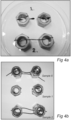
- the sheaths (the second layer) of Samples 1 and 2 each having a length of about 10 cm were stripped from the respective cable assembly and placed in a heating chamber, each sheath suspended between two supports. The temperature in the heating chamber was 150 °C. After 48 hours the samples were visually inspected. A photograph of the result is shown in Figure 4a . The test was repeated using samples 1, 2 and 5, and the result shown in Figure 4b . In both tests it was seen that the sheath material of Sample 1, that is the thermoplastic layer, was completely melted, whereas the second layer of each of Sample 2 and Sample 5, formed of a non-thermoplastic layer comprising a non-thermoplastic, crosslinked polyethylene material, essentially retained its shape and did not melt.
- Samples 1, 2 and 5 above were subjected to shrinkage measurement according to the standard IEC 60811-503 using the following settings; temperature +100°C, number of cycles: 5, time per cycle: 1 h.
- the results showed that the comparative sample 1, which had a sheath of thermoplastic material, exhibited an average shrinkage of 3.0 %, whereas inventive samples 2 and 5, with a non-thermoplastic sheath, each had an average shrinkage of 0.1 % as shown in Table 3 below.
- Example 1a i.e. Sample 2
- Example 1b Example 4
- Example 1d Example 1d
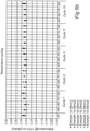
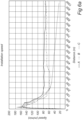
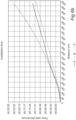
- Example 1a 2-fiber cable assemblies prepared according to Example 1a (i.e. Sample 2), Example 1b (Sample 4) and Example 1d (Sample 1), each having a length of 1000 m were wound up into a plastic pan and placed in a temperature cycling chamber. Two specimens per sample type were tested (denoted "fibre1" and "fibre2" respectively). The cable ends were prepared for measurements of the attentuation of the optical signal.
- the temperature cycle involved 12 hour dwell time at each of the temperatures -45°C, -50°C, +70 and +85°C. Attenuation measurements at wavelengths 1310 nm and 1550 nm started at room temperature (+20°C) and were performed during cycle 1, 2, 5, 7 and 10, at the temperatures indicated above in respect of Samples 1 and 2.
- Example 4 For the cable assembly of Example 1b (Sample 4), attenuation measurements were made only at temperatures +85°C and -50°C during cycle 1, 2, 5 and 10. Measuments were made using an optical time-domain reflectometer (OTDR) from Anritsu, model MW9076K.
- OTDR optical time-domain reflectometer
Landscapes
- Physics & Mathematics (AREA)
- Chemical & Material Sciences (AREA)
- General Physics & Mathematics (AREA)
- Optics & Photonics (AREA)
- Engineering & Computer Science (AREA)
- Organic Chemistry (AREA)
- Wood Science & Technology (AREA)
- Materials Engineering (AREA)
- Life Sciences & Earth Sciences (AREA)
- Manufacturing & Machinery (AREA)
- Health & Medical Sciences (AREA)
- Chemical Kinetics & Catalysis (AREA)
- Medicinal Chemistry (AREA)
- Polymers & Plastics (AREA)
- Insulated Conductors (AREA)
- Optical Fibers, Optical Fiber Cores, And Optical Fiber Bundles (AREA)
- Light Guides In General And Applications Therefor (AREA)
Claims (15)
- Kabelbaugruppe (1), angepasst, um in einem Kanal installiert zu werden mittels einer Kombination aus Einblasen und mechanischem Einführen, die Kabelbaugruppe aufweisend- mindestens ein flexibles Signalübertragungselement (2) zum Übertragen von optischen Signalen,- eine erste Schicht (3), die das mindestens eine flexible Signalübertragungselement (2) umschließt, sodass mindestens ein Signalübertragungselement in berührendem Kontakt mit der ersten Schicht steht, und- eine zweite Schicht (4), außerhalb der ersten Schicht angeordnet,dadurch gekennzeichnet, dass die zweite Schicht aus einer Zusammensetzung hergestellt ist, die ein Basismaterial aus Polyethylen aufweist, das angepasst ist, um quervernetzt zu werden, wodurch die zweite Schicht quervernetztes Polypropylen aufweist,wobei die zweite Schicht (4) ferner ein nichtquervernetztes Polyethylen aufweist, das eine höhere Dichte aufweist als das quervernetzte Polyethylenmaterial undwobei die zweite Schicht (4) einen Grad der Quervernetzung von mindestens 15 % aufweist, wie nach ISO 10147:2011 bestimmt.
- Kabelbaugruppe nach Anspruch 1, wobei die zweite Schicht (4) einen Grad der Quervernetzung von mindestens 30 % aufweist, wie nach ISO 10147:2011 bestimmt.
- Kabelbaugruppe nach Anspruch 1 oder 2, wobei die zweite Schicht (4) eine Schichtdicke von bis zu 400 µm aufweist, bevorzugt bis zu 200 µm, wie etwa ungefähr 190 µm.
- Kabelbaugruppe nach einem der vorhergehenden Ansprüche, wobei die zweite Schicht (4) das nicht quervernetzte Polyethylen mit einem Gehalt von mehr als 0 % bis 50 % aufweist, wie etwa von 10 % bis 50 %, über das Gewicht der zweiten Schicht berechnet.
- Kabelbaugruppe nach Anspruch 4, wobei das quervernetzte Polyethylen ein Polyethylen geringer Dichte oder ein Polyethylen mittlerer Dichte ist und die zweite Schicht ferner nicht quervernetztes HDPE in einem Gehalt von 20 % bis 50 % des Gewichts der zweiten Schicht aufweist.
- Kabelbaugruppe nach einem der vorhergehenden Ansprüche, wobei das quervernetzte Polyethylen und jedes weitere Polyethylen, das in der zweiten Schicht (4) enthalten ist, insgesamt eine Dichte im Bereich von 926 bis 960 kg/m3 aufweist, wie nach ISO 1183-1:2012 festgestellt wird.
- Kabelbaugruppe nach einem der vorhergehenden Ansprüche, wobei das quervernetzte Polyethylenmaterial ein silanquervernetztes Polyethylen ist.
- Kabelbaugruppe nach einem der vorhergehenden Ansprüche, wobei das Material der zweiten Schicht (4) homogen ist, indem es frei von Elementen wie Perlen, Kugeln, Flocken, Fasern oder dergleichen ist.
- Kabelbaugruppe nach einem der vorhergehenden Ansprüche, aufweisend mindestens zwei flexible Signalübertragungselemente (2) zum Übertragen optischer Signale.
- Verfahren zum Herstellen einer Kabelbaugruppe (1), umfassend mindestens ein flexibles Signalübertragungselement (2) zum Übertragen von optischen Signalen, umfassend die Schritte:a) Bereitstellen von mindestens einem Signalübertragungselement, das mit einer ersten Schicht (3) beschichtet ist;b) Bereitstellen einer geschmolzenen Zusammensetzung, die ein Basismaterial aus einem quervernetzbaren duroplastischen Polyethylen, das angepasst ist, quervernetzt zu werden, und optional ein Quervernetzungsmittel umfasst;c) Aufbringen der geschmolzenen Zusammensetzung um das mindestens eine Signalübertragungselement zum Bilden einer zweiten Schicht (4) der geschmolzenen Zusammensetzung außerhalb der ersten Schicht; undd) Erlauben, dass sich das quervernetzbare duroplastische Polyethylen quervernetzt,wobei die zweite Schicht (4) ferner ein nichtquervernetztes Polyethylen aufweist, das eine höhere Dichte aufweist als das quervernetzte Polyethylenmaterial undwobei die zweite Schicht (4) einen Grad der Quervernetzung von mindestens 15 % aufweist, wie nach ISO 10147:2011 bestimmt.
- Verfahren zum Herstellen einer Kabelbaugruppe nach Anspruch 10, wobei das Quervernetzen des quervernetzbaren duroplastischen Polyethylens die Aktion eines oder mehrerer quervernetzender Mittel verlangt, die aus der Gruppe gewählt werden, die umfasst: einen Katalysator, Wärme, Feuchtigkeit, UV-Strahlung und Gammastrahlung.
- Verfahren zum Herstellen einer Kabelbaugruppe nach Anspruch 11, wobei das duroplastische Polyethylen unter Verwendung eines Katalysators quervernetzbar ist und Schritt b) ferner das Mischen des quervernetzbaren duroplastischen Polyethylens und des Katalysators umfasst.
- Verfahren zum Herstellen einer Kabelbaugruppe nach Anspruch 12, wobei das Polyethylen und der Katalysator in einem trockenen Zustand gemischt werden, um eine Mischung zu bilden, und die Mischung nachfolgend geschmolzen wird.
- Verfahren zum Herstellen einer Kabelbaugruppe nach Anspruch 12 oder 13, wobei das duroplastische Polyethylen ein silanquervernetzbares Polyethylen ist und ein Silankatalysator mit dem duroplastischen Polyethylen gemischt oder zu der geschmolzenen Zusammensetzung hinzugefügt wird.
- Verfahren zum Installieren einer Kabelbaugruppe (1) nach einem der Ansprüche 1 bis 9, oder erzeugt nach einem der Ansprüche 10 bis 14, in einem Kanal, umfassend- Einführen der Baugruppe in und durch den Kanal mittels einer Kombination aus Einblasen mit Druckluft und mechanischem Einführen.
Priority Applications (1)
| Application Number | Priority Date | Filing Date | Title |
|---|---|---|---|
| EP24204949.2A EP4513243A1 (de) | 2017-09-13 | 2018-09-13 | Kabelmantelmaterial |
Applications Claiming Priority (2)
| Application Number | Priority Date | Filing Date | Title |
|---|---|---|---|
| EP17190947 | 2017-09-13 | ||
| PCT/EP2018/074787 WO2019053146A1 (en) | 2017-09-13 | 2018-09-13 | Cable sheath material |
Related Child Applications (1)
| Application Number | Title | Priority Date | Filing Date |
|---|---|---|---|
| EP24204949.2A Division EP4513243A1 (de) | 2017-09-13 | 2018-09-13 | Kabelmantelmaterial |
Publications (2)
| Publication Number | Publication Date |
|---|---|
| EP3682279A1 EP3682279A1 (de) | 2020-07-22 |
| EP3682279B1 true EP3682279B1 (de) | 2024-10-09 |
Family
ID=59895126
Family Applications (2)
| Application Number | Title | Priority Date | Filing Date |
|---|---|---|---|
| EP18765478.5A Active EP3682279B1 (de) | 2017-09-13 | 2018-09-13 | Kabelmantelmaterial |
| EP24204949.2A Pending EP4513243A1 (de) | 2017-09-13 | 2018-09-13 | Kabelmantelmaterial |
Family Applications After (1)
| Application Number | Title | Priority Date | Filing Date |
|---|---|---|---|
| EP24204949.2A Pending EP4513243A1 (de) | 2017-09-13 | 2018-09-13 | Kabelmantelmaterial |
Country Status (6)
| Country | Link |
|---|---|
| US (2) | US11460654B2 (de) |
| EP (2) | EP3682279B1 (de) |
| AU (1) | AU2018332050B2 (de) |
| CA (1) | CA3075581A1 (de) |
| FI (1) | FI3682279T3 (de) |
| WO (1) | WO2019053146A1 (de) |
Families Citing this family (7)
| Publication number | Priority date | Publication date | Assignee | Title |
|---|---|---|---|---|
| ES3026708T3 (en) | 2018-03-20 | 2025-06-12 | Commscope Technologies Llc | Fiber optic cable terminal with a pushable stub cable |
| GB201902716D0 (en) | 2019-02-28 | 2019-04-17 | Emtelle Uk Ltd | Fibre optic cable, methods of manufacture and use thereof |
| GB2609649B (en) | 2021-08-12 | 2025-07-23 | Emtelle Uk Ltd | Pre-terminated optical fibre cable assembly, kits of parts, methods of manufacture and installation thereof |
| EP4533154A1 (de) | 2022-05-26 | 2025-04-09 | Emtelle UK Ltd | Zubehör zum schutz gespleisster glasfasern, glasfaserkabelanordnungen, teilekits, verfahren zur herstellung und installation davon |
| CN115028986B (zh) * | 2022-06-27 | 2023-06-23 | 重庆泰山电缆有限公司 | 电缆护套材料及制备方法 |
| WO2025104438A1 (en) | 2023-11-14 | 2025-05-22 | Emtelle Uk Limited | Cable and method of manufacturing a cable |
| CN119978584A (zh) * | 2024-12-31 | 2025-05-13 | 无锡鸿仪新材料科技有限公司 | 一种耐磨高强度硅烷交联聚乙烯绝缘料及其制备方法 |
Citations (11)
| Publication number | Priority date | Publication date | Assignee | Title |
|---|---|---|---|---|
| EP0241330A2 (de) | 1986-03-13 | 1987-10-14 | Standard Telefon Og Kabelfabrik A/S | Ölfestes Kabel |
| WO1993005424A1 (en) | 1991-09-10 | 1993-03-18 | Neste Oy | Optical cable |
| EP0858082A1 (de) | 1997-02-10 | 1998-08-12 | PIRELLI CAVI E SISTEMI S.p.A. | Feuchtigkeitsfestes Kabel |
| US20030035635A1 (en) | 2001-08-13 | 2003-02-20 | Chastain Scott M. | Air blown fiber (ABF) cable with low composite coefficient of thermal expansion |
| JP2004077560A (ja) | 2002-08-09 | 2004-03-11 | Furukawa Electric Co Ltd:The | 光ファイバケーブル |
| US20040071416A1 (en) | 2002-10-15 | 2004-04-15 | Militaru Cristian I. | Optical cable having an increased resistance to dry band arcing and method for its manufacture |
| EP1821124A1 (de) | 2002-08-10 | 2007-08-22 | Emtelle UK Limited | Signalübertragungskabel |
| US7501469B1 (en) | 2006-02-16 | 2009-03-10 | Hendrix Wire & Cable, Inc. | Cross-linked polyolefin material blend |
| WO2014099360A1 (en) | 2012-12-21 | 2014-06-26 | Dow Global Technologies Llc | Polyolefin-based compound for cable jacket with reduced shrinkage and enhanced processability |
| US20140241679A1 (en) | 2013-02-28 | 2014-08-28 | Adc Telecommunications, Inc. | Power cable with ability to provide optical fiber upgrade |
| WO2015054893A1 (en) | 2013-10-18 | 2015-04-23 | Dow Global Technologies Llc | Optical fiber cable components |
Family Cites Families (24)
| Publication number | Priority date | Publication date | Assignee | Title |
|---|---|---|---|---|
| US495021A (en) | 1893-04-11 | Sash-cord guide | ||
| EP0108590B1 (de) | 1982-11-08 | 1986-11-26 | BRITISH TELECOMMUNICATIONS public limited company | Optische Übertragungsfasern |
| EP0157610B1 (de) | 1984-03-29 | 1989-09-13 | BRITISH TELECOMMUNICATIONS public limited company | Mantel für optische Fasern |
| WO1993001512A1 (en) | 1991-07-01 | 1993-01-21 | British Telecommunications Public Limited Company | Optical fibres |
| GB2282897B (en) | 1993-10-01 | 1996-10-23 | Pirelli General Plc | Optical fibre assembly with coating having projecting particulate material for blown installation |
| US7562861B2 (en) * | 2005-04-01 | 2009-07-21 | Verizon Business Global Llc | Systems and methods for controlling duct pressurization for cable installation |
| US20070299043A1 (en) * | 2005-10-03 | 2007-12-27 | Hunter William L | Anti-scarring drug combinations and use thereof |
| CN1962741A (zh) * | 2005-11-09 | 2007-05-16 | 无锡市沪安电线电缆有限公司 | 硅烷交联聚烯烃电缆料 |
| US20100158457A1 (en) * | 2008-12-19 | 2010-06-24 | Amphenol Corporation | Ruggedized, lightweight, and compact fiber optic cable |
| JP5552759B2 (ja) * | 2009-06-19 | 2014-07-16 | 日立金属株式会社 | 発泡用樹脂組成物および高周波同軸ケーブル |
| CA2774284C (en) * | 2009-09-16 | 2017-11-28 | Union Carbide Chemicals & Plastics Technology Llc | Crosslinked, melt-shaped articles and compositions for producing same |
| US20140265322A1 (en) * | 2013-03-15 | 2014-09-18 | Steven L. Thompson | Conduit coupler with collar |
| US20160001482A1 (en) * | 2013-04-19 | 2016-01-07 | Mitsubishi Electric Corporation | Method of manufacturing molded product of silane crosslinked polyethylene resin, method of manufacturing rod-shaped molded product, and manufacturing apparatus therefor |
| KR102225853B1 (ko) * | 2013-07-16 | 2021-03-12 | 다우 글로벌 테크놀로지스 엘엘씨 | 가요성 전력 케이블 절연 |
| DE102013216502A1 (de) * | 2013-08-21 | 2015-02-26 | Evonik Industries Ag | Zinn-freie Zusammensetzung für die Vernetzung von thermoplastischen Polyolefinen |
| PL3120176T3 (pl) * | 2014-03-18 | 2022-01-10 | Corning Optical Communications LLC | Płaszcz dla kabla światłowodowego |
| US10809475B2 (en) * | 2014-03-18 | 2020-10-20 | Corning Optical Communications LLC | Jacket for a fiber optic cable |
| CA2947866C (en) * | 2014-05-02 | 2023-09-19 | Afl Telecommunications Llc | Optical broadband node cable |
| BR112016029968B1 (pt) * | 2014-06-27 | 2022-01-18 | Dow Global Technologies Llc | Artigo retrátil a frio, cabo e método de emenda de um cabo |
| WO2016077496A1 (en) * | 2014-11-11 | 2016-05-19 | General Cable Technologies Corporation | Heat shield for cables |
| KR101644246B1 (ko) * | 2014-11-19 | 2016-08-01 | 주식회사 엘지화학 | 가교 폴리에틸렌 수지 조성물 |
| US10538210B2 (en) * | 2016-06-02 | 2020-01-21 | Sumitomo Electric Industries, Ltd. | Multi-core cable for vehicle |
| JP2018037153A (ja) * | 2016-08-29 | 2018-03-08 | 大電株式会社 | ケーブル |
| JP6839547B2 (ja) * | 2017-01-25 | 2021-03-10 | 古河電気工業株式会社 | 難燃性樹脂組成物、並びに、それを用いた成形部品及び配線材 |
-
2018
- 2018-09-13 US US16/647,228 patent/US11460654B2/en active Active
- 2018-09-13 EP EP18765478.5A patent/EP3682279B1/de active Active
- 2018-09-13 EP EP24204949.2A patent/EP4513243A1/de active Pending
- 2018-09-13 WO PCT/EP2018/074787 patent/WO2019053146A1/en not_active Ceased
- 2018-09-13 AU AU2018332050A patent/AU2018332050B2/en active Active
- 2018-09-13 FI FIEP18765478.5T patent/FI3682279T3/fi active
- 2018-09-13 CA CA3075581A patent/CA3075581A1/en active Pending
-
2022
- 2022-09-30 US US17/937,182 patent/US12353035B2/en active Active
Patent Citations (12)
| Publication number | Priority date | Publication date | Assignee | Title |
|---|---|---|---|---|
| EP0241330A2 (de) | 1986-03-13 | 1987-10-14 | Standard Telefon Og Kabelfabrik A/S | Ölfestes Kabel |
| WO1993005424A1 (en) | 1991-09-10 | 1993-03-18 | Neste Oy | Optical cable |
| EP0858082A1 (de) | 1997-02-10 | 1998-08-12 | PIRELLI CAVI E SISTEMI S.p.A. | Feuchtigkeitsfestes Kabel |
| US20030035635A1 (en) | 2001-08-13 | 2003-02-20 | Chastain Scott M. | Air blown fiber (ABF) cable with low composite coefficient of thermal expansion |
| US6968106B2 (en) | 2001-08-13 | 2005-11-22 | Sumitomo Electric Lightwave Corp. | Air blown fiber (ABF) cable with low composite coefficient of thermal expansion |
| JP2004077560A (ja) | 2002-08-09 | 2004-03-11 | Furukawa Electric Co Ltd:The | 光ファイバケーブル |
| EP1821124A1 (de) | 2002-08-10 | 2007-08-22 | Emtelle UK Limited | Signalübertragungskabel |
| US20040071416A1 (en) | 2002-10-15 | 2004-04-15 | Militaru Cristian I. | Optical cable having an increased resistance to dry band arcing and method for its manufacture |
| US7501469B1 (en) | 2006-02-16 | 2009-03-10 | Hendrix Wire & Cable, Inc. | Cross-linked polyolefin material blend |
| WO2014099360A1 (en) | 2012-12-21 | 2014-06-26 | Dow Global Technologies Llc | Polyolefin-based compound for cable jacket with reduced shrinkage and enhanced processability |
| US20140241679A1 (en) | 2013-02-28 | 2014-08-28 | Adc Telecommunications, Inc. | Power cable with ability to provide optical fiber upgrade |
| WO2015054893A1 (en) | 2013-10-18 | 2015-04-23 | Dow Global Technologies Llc | Optical fiber cable components |
Non-Patent Citations (3)
| Title |
|---|
| "ISO 10147:2011 Pipes and fittings made of crosslinked polyethylene (PE-X) -- Estimation of the degree of crosslinking by determination of the gel content", ISO STANDARD, ISO, CH, vol. 10147, 1 September 2011 (2011-09-01), CH , pages 1 - 8, XP008180767 |
| ANONYMOUS: "Piping Equations - Calculate cross-sectional areas, weight of empty pipes, weight of pipes filled with water, inside and outside surface areas", THE ENGINEERING TOOLBOX (ACCESSED VIA THE WAYBACK MACHINE), 29 May 2025 (2025-05-29), XP093298768, Retrieved from the Internet <URL:https://web.archive.org/web/20250529071144/https://www.engineeringtoolbox.com/pipes-equations-d_873.html> |
| THE ENGINEERING TOOLBOX: "Pipe Weight Calculator (no date found)", 4 August 2017 (2017-08-04), Retrieved from the Internet <URL:https://www.engineeringtoolbox.com/pipes-equations-d_873.html> [retrieved on 20250708] |
Also Published As
| Publication number | Publication date |
|---|---|
| EP3682279A1 (de) | 2020-07-22 |
| US20230049582A1 (en) | 2023-02-16 |
| AU2018332050B2 (en) | 2024-05-16 |
| US20210033808A1 (en) | 2021-02-04 |
| US11460654B2 (en) | 2022-10-04 |
| FI3682279T3 (fi) | 2025-01-10 |
| US12353035B2 (en) | 2025-07-08 |
| AU2018332050A1 (en) | 2020-04-30 |
| CA3075581A1 (en) | 2019-03-21 |
| EP4513243A1 (de) | 2025-02-26 |
| WO2019053146A1 (en) | 2019-03-21 |
Similar Documents
| Publication | Publication Date | Title |
|---|---|---|
| US12353035B2 (en) | Cable sheath material | |
| US6853781B2 (en) | Air blown fiber (ABF) cable with low composite coefficient of thermal expansion | |
| US6253012B1 (en) | Cycled fiber lock for cross-functional totally dry optical fiber loose tube cable | |
| US6654527B2 (en) | Optical fiber cable | |
| JP4856180B2 (ja) | 機械的に剥ぎ取り可能なアップコーテッド光ファイバ | |
| US6389204B1 (en) | Fiber optic cables with strength members and methods of making the same | |
| US20080280051A1 (en) | Low cost, high performance, flexible, water-swellable reinforcement for communications cable | |
| US4270840A (en) | Glass fibers for optical transmission | |
| EP1376181B1 (de) | Optische Fasern mit Pufferschicht und zugehöriges Herstellungsverfahren | |
| CN111066099A (zh) | 光纤电缆组件的聚合组合物 | |
| GB2198258A (en) | Optical wave-guides | |
| KR20120104802A (ko) | 유연성 및 내충격성이 우수한 고강도 루즈튜브형 광케이블용 조성물 | |
| JP7208719B2 (ja) | 光ファイバケーブル用線状体、繊維強化光ファイバケーブル及び光ファイバセンサ | |
| JP2009133958A (ja) | オーバーコート心線及びケーブル | |
| US11391900B2 (en) | Talcum-free flame retardant fiber optical cable with micro-modules | |
| EP1944638A2 (de) | Kostengünstige und flexible Hochleitungsverstärkung für ein Kommunikationskabel | |
| JPH11258469A (ja) | 光ファイバ心線および光ファイバコ―ド | |
| JP2001318285A (ja) | 光ファイバケーブル | |
| EP4036622A1 (de) | Glasfasereinheit für einblasinstallationen | |
| AU617173B2 (en) | A pressure transporting system for an improved fibre | |
| JPH08208278A (ja) | 光ファイバ心線 | |
| JPS61128215A (ja) | プラスチツク光フアイバ | |
| JPH0253765B2 (de) | ||
| DD264355A3 (de) | Beschichtung fuer eine optische faser der lichtwellenuebertragung |
Legal Events
| Date | Code | Title | Description |
|---|---|---|---|
| STAA | Information on the status of an ep patent application or granted ep patent |
Free format text: STATUS: UNKNOWN |
|
| STAA | Information on the status of an ep patent application or granted ep patent |
Free format text: STATUS: THE INTERNATIONAL PUBLICATION HAS BEEN MADE |
|
| PUAI | Public reference made under article 153(3) epc to a published international application that has entered the european phase |
Free format text: ORIGINAL CODE: 0009012 |
|
| STAA | Information on the status of an ep patent application or granted ep patent |
Free format text: STATUS: REQUEST FOR EXAMINATION WAS MADE |
|
| 17P | Request for examination filed |
Effective date: 20200403 |
|
| AK | Designated contracting states |
Kind code of ref document: A1 Designated state(s): AL AT BE BG CH CY CZ DE DK EE ES FI FR GB GR HR HU IE IS IT LI LT LU LV MC MK MT NL NO PL PT RO RS SE SI SK SM TR |
|
| AX | Request for extension of the european patent |
Extension state: BA ME |
|
| DAV | Request for validation of the european patent (deleted) | ||
| DAX | Request for extension of the european patent (deleted) | ||
| STAA | Information on the status of an ep patent application or granted ep patent |
Free format text: STATUS: EXAMINATION IS IN PROGRESS |
|
| 17Q | First examination report despatched |
Effective date: 20220105 |
|
| P01 | Opt-out of the competence of the unified patent court (upc) registered |
Effective date: 20230421 |
|
| TPAC | Observations filed by third parties |
Free format text: ORIGINAL CODE: EPIDOSNTIPA |
|
| GRAP | Despatch of communication of intention to grant a patent |
Free format text: ORIGINAL CODE: EPIDOSNIGR1 |
|
| STAA | Information on the status of an ep patent application or granted ep patent |
Free format text: STATUS: GRANT OF PATENT IS INTENDED |
|
| INTG | Intention to grant announced |
Effective date: 20240507 |
|
| TPAC | Observations filed by third parties |
Free format text: ORIGINAL CODE: EPIDOSNTIPA |
|
| GRAS | Grant fee paid |
Free format text: ORIGINAL CODE: EPIDOSNIGR3 |
|
| GRAA | (expected) grant |
Free format text: ORIGINAL CODE: 0009210 |
|
| STAA | Information on the status of an ep patent application or granted ep patent |
Free format text: STATUS: THE PATENT HAS BEEN GRANTED |
|
| AK | Designated contracting states |
Kind code of ref document: B1 Designated state(s): AL AT BE BG CH CY CZ DE DK EE ES FI FR GB GR HR HU IE IS IT LI LT LU LV MC MK MT NL NO PL PT RO RS SE SI SK SM TR |
|
| REG | Reference to a national code |
Ref country code: CH Ref legal event code: EP |
|
| REG | Reference to a national code |
Ref country code: DE Ref legal event code: R096 Ref document number: 602018075215 Country of ref document: DE |
|
| REG | Reference to a national code |
Ref country code: IE Ref legal event code: FG4D |
|
| REG | Reference to a national code |
Ref country code: SE Ref legal event code: TRGR |
|
| REG | Reference to a national code |
Ref country code: FI Ref legal event code: FGE |
|
| REG | Reference to a national code |
Ref country code: LT Ref legal event code: MG9D |
|
| REG | Reference to a national code |
Ref country code: NL Ref legal event code: MP Effective date: 20241009 |
|
| PG25 | Lapsed in a contracting state [announced via postgrant information from national office to epo] |
Ref country code: NL Free format text: LAPSE BECAUSE OF FAILURE TO SUBMIT A TRANSLATION OF THE DESCRIPTION OR TO PAY THE FEE WITHIN THE PRESCRIBED TIME-LIMIT Effective date: 20241009 |
|
| PG25 | Lapsed in a contracting state [announced via postgrant information from national office to epo] |
Ref country code: NL Free format text: LAPSE BECAUSE OF FAILURE TO SUBMIT A TRANSLATION OF THE DESCRIPTION OR TO PAY THE FEE WITHIN THE PRESCRIBED TIME-LIMIT Effective date: 20241009 |
|
| PG25 | Lapsed in a contracting state [announced via postgrant information from national office to epo] |
Ref country code: IS Free format text: LAPSE BECAUSE OF FAILURE TO SUBMIT A TRANSLATION OF THE DESCRIPTION OR TO PAY THE FEE WITHIN THE PRESCRIBED TIME-LIMIT Effective date: 20250209 Ref country code: PT Free format text: LAPSE BECAUSE OF FAILURE TO SUBMIT A TRANSLATION OF THE DESCRIPTION OR TO PAY THE FEE WITHIN THE PRESCRIBED TIME-LIMIT Effective date: 20250210 Ref country code: HR Free format text: LAPSE BECAUSE OF FAILURE TO SUBMIT A TRANSLATION OF THE DESCRIPTION OR TO PAY THE FEE WITHIN THE PRESCRIBED TIME-LIMIT Effective date: 20241009 |
|
| PG25 | Lapsed in a contracting state [announced via postgrant information from national office to epo] |
Ref country code: BG Free format text: LAPSE BECAUSE OF FAILURE TO SUBMIT A TRANSLATION OF THE DESCRIPTION OR TO PAY THE FEE WITHIN THE PRESCRIBED TIME-LIMIT Effective date: 20241009 |
|
| PG25 | Lapsed in a contracting state [announced via postgrant information from national office to epo] |
Ref country code: ES Free format text: LAPSE BECAUSE OF FAILURE TO SUBMIT A TRANSLATION OF THE DESCRIPTION OR TO PAY THE FEE WITHIN THE PRESCRIBED TIME-LIMIT Effective date: 20241009 |
|
| PG25 | Lapsed in a contracting state [announced via postgrant information from national office to epo] |
Ref country code: LV Free format text: LAPSE BECAUSE OF FAILURE TO SUBMIT A TRANSLATION OF THE DESCRIPTION OR TO PAY THE FEE WITHIN THE PRESCRIBED TIME-LIMIT Effective date: 20241009 Ref country code: GR Free format text: LAPSE BECAUSE OF FAILURE TO SUBMIT A TRANSLATION OF THE DESCRIPTION OR TO PAY THE FEE WITHIN THE PRESCRIBED TIME-LIMIT Effective date: 20250110 |
|
| PG25 | Lapsed in a contracting state [announced via postgrant information from national office to epo] |
Ref country code: PL Free format text: LAPSE BECAUSE OF FAILURE TO SUBMIT A TRANSLATION OF THE DESCRIPTION OR TO PAY THE FEE WITHIN THE PRESCRIBED TIME-LIMIT Effective date: 20241009 |
|
| PG25 | Lapsed in a contracting state [announced via postgrant information from national office to epo] |
Ref country code: RS Free format text: LAPSE BECAUSE OF FAILURE TO SUBMIT A TRANSLATION OF THE DESCRIPTION OR TO PAY THE FEE WITHIN THE PRESCRIBED TIME-LIMIT Effective date: 20250109 |
|
| PG25 | Lapsed in a contracting state [announced via postgrant information from national office to epo] |
Ref country code: SM Free format text: LAPSE BECAUSE OF FAILURE TO SUBMIT A TRANSLATION OF THE DESCRIPTION OR TO PAY THE FEE WITHIN THE PRESCRIBED TIME-LIMIT Effective date: 20241009 |
|
| REG | Reference to a national code |
Ref country code: DE Ref legal event code: R026 Ref document number: 602018075215 Country of ref document: DE |
|
| PG25 | Lapsed in a contracting state [announced via postgrant information from national office to epo] |
Ref country code: DK Free format text: LAPSE BECAUSE OF FAILURE TO SUBMIT A TRANSLATION OF THE DESCRIPTION OR TO PAY THE FEE WITHIN THE PRESCRIBED TIME-LIMIT Effective date: 20241009 |
|
| PLBI | Opposition filed |
Free format text: ORIGINAL CODE: 0009260 |
|
| PG25 | Lapsed in a contracting state [announced via postgrant information from national office to epo] |
Ref country code: EE Free format text: LAPSE BECAUSE OF FAILURE TO SUBMIT A TRANSLATION OF THE DESCRIPTION OR TO PAY THE FEE WITHIN THE PRESCRIBED TIME-LIMIT Effective date: 20241009 |
|
| PLAX | Notice of opposition and request to file observation + time limit sent |
Free format text: ORIGINAL CODE: EPIDOSNOBS2 |
|
| PG25 | Lapsed in a contracting state [announced via postgrant information from national office to epo] |
Ref country code: RO Free format text: LAPSE BECAUSE OF FAILURE TO SUBMIT A TRANSLATION OF THE DESCRIPTION OR TO PAY THE FEE WITHIN THE PRESCRIBED TIME-LIMIT Effective date: 20241009 |
|
| PG25 | Lapsed in a contracting state [announced via postgrant information from national office to epo] |
Ref country code: SK Free format text: LAPSE BECAUSE OF FAILURE TO SUBMIT A TRANSLATION OF THE DESCRIPTION OR TO PAY THE FEE WITHIN THE PRESCRIBED TIME-LIMIT Effective date: 20241009 |
|
| PG25 | Lapsed in a contracting state [announced via postgrant information from national office to epo] |
Ref country code: CZ Free format text: LAPSE BECAUSE OF FAILURE TO SUBMIT A TRANSLATION OF THE DESCRIPTION OR TO PAY THE FEE WITHIN THE PRESCRIBED TIME-LIMIT Effective date: 20241009 |
|
| PG25 | Lapsed in a contracting state [announced via postgrant information from national office to epo] |
Ref country code: IT Free format text: LAPSE BECAUSE OF FAILURE TO SUBMIT A TRANSLATION OF THE DESCRIPTION OR TO PAY THE FEE WITHIN THE PRESCRIBED TIME-LIMIT Effective date: 20241009 |
|
| 26 | Opposition filed |
Opponent name: EMTELLE UK LIMITED Effective date: 20250709 |
|
| PGFP | Annual fee paid to national office [announced via postgrant information from national office to epo] |
Ref country code: FI Payment date: 20250805 Year of fee payment: 8 |
|
| PGFP | Annual fee paid to national office [announced via postgrant information from national office to epo] |
Ref country code: DE Payment date: 20250806 Year of fee payment: 8 |
|
| PGFP | Annual fee paid to national office [announced via postgrant information from national office to epo] |
Ref country code: NO Payment date: 20250807 Year of fee payment: 8 |
|
| PGFP | Annual fee paid to national office [announced via postgrant information from national office to epo] |
Ref country code: GB Payment date: 20250805 Year of fee payment: 8 |
|
| PGFP | Annual fee paid to national office [announced via postgrant information from national office to epo] |
Ref country code: AT Payment date: 20250806 Year of fee payment: 8 |
|
| PGFP | Annual fee paid to national office [announced via postgrant information from national office to epo] |
Ref country code: SE Payment date: 20250805 Year of fee payment: 8 |
|
| PLBB | Reply of patent proprietor to notice(s) of opposition received |
Free format text: ORIGINAL CODE: EPIDOSNOBS3 |