EP3681846B1 - Deadfront for displays including a touch panel on decorative glass and related methods - Google Patents
Deadfront for displays including a touch panel on decorative glass and related methods Download PDFInfo
- Publication number
- EP3681846B1 EP3681846B1 EP18779527.3A EP18779527A EP3681846B1 EP 3681846 B1 EP3681846 B1 EP 3681846B1 EP 18779527 A EP18779527 A EP 18779527A EP 3681846 B1 EP3681846 B1 EP 3681846B1
- Authority
- EP
- European Patent Office
- Prior art keywords
- layer
- mol
- deadfront
- deadfront article
- contrast
- Prior art date
- Legal status (The legal status is an assumption and is not a legal conclusion. Google has not performed a legal analysis and makes no representation as to the accuracy of the status listed.)
- Active
Links
Images








Classifications
-
- C—CHEMISTRY; METALLURGY
- C03—GLASS; MINERAL OR SLAG WOOL
- C03C—CHEMICAL COMPOSITION OF GLASSES, GLAZES OR VITREOUS ENAMELS; SURFACE TREATMENT OF GLASS; SURFACE TREATMENT OF FIBRES OR FILAMENTS MADE FROM GLASS, MINERALS OR SLAGS; JOINING GLASS TO GLASS OR OTHER MATERIALS
- C03C17/00—Surface treatment of glass, not in the form of fibres or filaments, by coating
- C03C17/001—General methods for coating; Devices therefor
-
- G—PHYSICS
- G09—EDUCATION; CRYPTOGRAPHY; DISPLAY; ADVERTISING; SEALS
- G09F—DISPLAYING; ADVERTISING; SIGNS; LABELS OR NAME-PLATES; SEALS
- G09F9/00—Indicating arrangements for variable information in which the information is built-up on a support by selection or combination of individual elements
- G09F9/30—Indicating arrangements for variable information in which the information is built-up on a support by selection or combination of individual elements in which the desired character or characters are formed by combining individual elements
- G09F9/33—Indicating arrangements for variable information in which the information is built-up on a support by selection or combination of individual elements in which the desired character or characters are formed by combining individual elements being semiconductor devices, e.g. diodes
-
- B—PERFORMING OPERATIONS; TRANSPORTING
- B60—VEHICLES IN GENERAL
- B60K—ARRANGEMENT OR MOUNTING OF PROPULSION UNITS OR OF TRANSMISSIONS IN VEHICLES; ARRANGEMENT OR MOUNTING OF PLURAL DIVERSE PRIME-MOVERS IN VEHICLES; AUXILIARY DRIVES FOR VEHICLES; INSTRUMENTATION OR DASHBOARDS FOR VEHICLES; ARRANGEMENTS IN CONNECTION WITH COOLING, AIR INTAKE, GAS EXHAUST OR FUEL SUPPLY OF PROPULSION UNITS IN VEHICLES
- B60K35/00—Instruments specially adapted for vehicles; Arrangement of instruments in or on vehicles
-
- B—PERFORMING OPERATIONS; TRANSPORTING
- B60—VEHICLES IN GENERAL
- B60K—ARRANGEMENT OR MOUNTING OF PROPULSION UNITS OR OF TRANSMISSIONS IN VEHICLES; ARRANGEMENT OR MOUNTING OF PLURAL DIVERSE PRIME-MOVERS IN VEHICLES; AUXILIARY DRIVES FOR VEHICLES; INSTRUMENTATION OR DASHBOARDS FOR VEHICLES; ARRANGEMENTS IN CONNECTION WITH COOLING, AIR INTAKE, GAS EXHAUST OR FUEL SUPPLY OF PROPULSION UNITS IN VEHICLES
- B60K35/00—Instruments specially adapted for vehicles; Arrangement of instruments in or on vehicles
- B60K35/20—Output arrangements, i.e. from vehicle to user, associated with vehicle functions or specially adapted therefor
- B60K35/21—Output arrangements, i.e. from vehicle to user, associated with vehicle functions or specially adapted therefor using visual output, e.g. blinking lights or matrix displays
- B60K35/22—Display screens
-
- C—CHEMISTRY; METALLURGY
- C03—GLASS; MINERAL OR SLAG WOOL
- C03B—MANUFACTURE, SHAPING, OR SUPPLEMENTARY PROCESSES
- C03B23/00—Re-forming shaped glass
- C03B23/02—Re-forming glass sheets
- C03B23/023—Re-forming glass sheets by bending
-
- C—CHEMISTRY; METALLURGY
- C03—GLASS; MINERAL OR SLAG WOOL
- C03C—CHEMICAL COMPOSITION OF GLASSES, GLAZES OR VITREOUS ENAMELS; SURFACE TREATMENT OF GLASS; SURFACE TREATMENT OF FIBRES OR FILAMENTS MADE FROM GLASS, MINERALS OR SLAGS; JOINING GLASS TO GLASS OR OTHER MATERIALS
- C03C15/00—Surface treatment of glass, not in the form of fibres or filaments, by etching
-
- C—CHEMISTRY; METALLURGY
- C03—GLASS; MINERAL OR SLAG WOOL
- C03C—CHEMICAL COMPOSITION OF GLASSES, GLAZES OR VITREOUS ENAMELS; SURFACE TREATMENT OF GLASS; SURFACE TREATMENT OF FIBRES OR FILAMENTS MADE FROM GLASS, MINERALS OR SLAGS; JOINING GLASS TO GLASS OR OTHER MATERIALS
- C03C15/00—Surface treatment of glass, not in the form of fibres or filaments, by etching
- C03C15/02—Surface treatment of glass, not in the form of fibres or filaments, by etching for making a smooth surface
-
- C—CHEMISTRY; METALLURGY
- C03—GLASS; MINERAL OR SLAG WOOL
- C03C—CHEMICAL COMPOSITION OF GLASSES, GLAZES OR VITREOUS ENAMELS; SURFACE TREATMENT OF GLASS; SURFACE TREATMENT OF FIBRES OR FILAMENTS MADE FROM GLASS, MINERALS OR SLAGS; JOINING GLASS TO GLASS OR OTHER MATERIALS
- C03C17/00—Surface treatment of glass, not in the form of fibres or filaments, by coating
- C03C17/34—Surface treatment of glass, not in the form of fibres or filaments, by coating with at least two coatings having different compositions
-
- C—CHEMISTRY; METALLURGY
- C03—GLASS; MINERAL OR SLAG WOOL
- C03C—CHEMICAL COMPOSITION OF GLASSES, GLAZES OR VITREOUS ENAMELS; SURFACE TREATMENT OF GLASS; SURFACE TREATMENT OF FIBRES OR FILAMENTS MADE FROM GLASS, MINERALS OR SLAGS; JOINING GLASS TO GLASS OR OTHER MATERIALS
- C03C17/00—Surface treatment of glass, not in the form of fibres or filaments, by coating
- C03C17/34—Surface treatment of glass, not in the form of fibres or filaments, by coating with at least two coatings having different compositions
- C03C17/3405—Surface treatment of glass, not in the form of fibres or filaments, by coating with at least two coatings having different compositions with at least two coatings of organic materials
-
- C—CHEMISTRY; METALLURGY
- C03—GLASS; MINERAL OR SLAG WOOL
- C03C—CHEMICAL COMPOSITION OF GLASSES, GLAZES OR VITREOUS ENAMELS; SURFACE TREATMENT OF GLASS; SURFACE TREATMENT OF FIBRES OR FILAMENTS MADE FROM GLASS, MINERALS OR SLAGS; JOINING GLASS TO GLASS OR OTHER MATERIALS
- C03C17/00—Surface treatment of glass, not in the form of fibres or filaments, by coating
- C03C17/34—Surface treatment of glass, not in the form of fibres or filaments, by coating with at least two coatings having different compositions
- C03C17/36—Surface treatment of glass, not in the form of fibres or filaments, by coating with at least two coatings having different compositions at least one coating being a metal
- C03C17/38—Surface treatment of glass, not in the form of fibres or filaments, by coating with at least two coatings having different compositions at least one coating being a metal at least one coating being a coating of an organic material
-
- C—CHEMISTRY; METALLURGY
- C03—GLASS; MINERAL OR SLAG WOOL
- C03C—CHEMICAL COMPOSITION OF GLASSES, GLAZES OR VITREOUS ENAMELS; SURFACE TREATMENT OF GLASS; SURFACE TREATMENT OF FIBRES OR FILAMENTS MADE FROM GLASS, MINERALS OR SLAGS; JOINING GLASS TO GLASS OR OTHER MATERIALS
- C03C19/00—Surface treatment of glass, not in the form of fibres or filaments, by mechanical means
-
- C—CHEMISTRY; METALLURGY
- C03—GLASS; MINERAL OR SLAG WOOL
- C03C—CHEMICAL COMPOSITION OF GLASSES, GLAZES OR VITREOUS ENAMELS; SURFACE TREATMENT OF GLASS; SURFACE TREATMENT OF FIBRES OR FILAMENTS MADE FROM GLASS, MINERALS OR SLAGS; JOINING GLASS TO GLASS OR OTHER MATERIALS
- C03C3/00—Glass compositions
- C03C3/04—Glass compositions containing silica
- C03C3/076—Glass compositions containing silica with 40% to 90% silica, by weight
- C03C3/078—Glass compositions containing silica with 40% to 90% silica, by weight containing an oxide of a divalent metal, e.g. an oxide of zinc
-
- C—CHEMISTRY; METALLURGY
- C03—GLASS; MINERAL OR SLAG WOOL
- C03C—CHEMICAL COMPOSITION OF GLASSES, GLAZES OR VITREOUS ENAMELS; SURFACE TREATMENT OF GLASS; SURFACE TREATMENT OF FIBRES OR FILAMENTS MADE FROM GLASS, MINERALS OR SLAGS; JOINING GLASS TO GLASS OR OTHER MATERIALS
- C03C3/00—Glass compositions
- C03C3/04—Glass compositions containing silica
- C03C3/076—Glass compositions containing silica with 40% to 90% silica, by weight
- C03C3/083—Glass compositions containing silica with 40% to 90% silica, by weight containing aluminium oxide or an iron compound
-
- C—CHEMISTRY; METALLURGY
- C03—GLASS; MINERAL OR SLAG WOOL
- C03C—CHEMICAL COMPOSITION OF GLASSES, GLAZES OR VITREOUS ENAMELS; SURFACE TREATMENT OF GLASS; SURFACE TREATMENT OF FIBRES OR FILAMENTS MADE FROM GLASS, MINERALS OR SLAGS; JOINING GLASS TO GLASS OR OTHER MATERIALS
- C03C3/00—Glass compositions
- C03C3/04—Glass compositions containing silica
- C03C3/076—Glass compositions containing silica with 40% to 90% silica, by weight
- C03C3/089—Glass compositions containing silica with 40% to 90% silica, by weight containing boron
-
- C—CHEMISTRY; METALLURGY
- C03—GLASS; MINERAL OR SLAG WOOL
- C03C—CHEMICAL COMPOSITION OF GLASSES, GLAZES OR VITREOUS ENAMELS; SURFACE TREATMENT OF GLASS; SURFACE TREATMENT OF FIBRES OR FILAMENTS MADE FROM GLASS, MINERALS OR SLAGS; JOINING GLASS TO GLASS OR OTHER MATERIALS
- C03C3/00—Glass compositions
- C03C3/04—Glass compositions containing silica
- C03C3/076—Glass compositions containing silica with 40% to 90% silica, by weight
- C03C3/089—Glass compositions containing silica with 40% to 90% silica, by weight containing boron
- C03C3/091—Glass compositions containing silica with 40% to 90% silica, by weight containing boron containing aluminium
-
- C—CHEMISTRY; METALLURGY
- C08—ORGANIC MACROMOLECULAR COMPOUNDS; THEIR PREPARATION OR CHEMICAL WORKING-UP; COMPOSITIONS BASED THEREON
- C08J—WORKING-UP; GENERAL PROCESSES OF COMPOUNDING; AFTER-TREATMENT NOT COVERED BY SUBCLASSES C08B, C08C, C08F, C08G or C08H
- C08J7/00—Chemical treatment or coating of shaped articles made of macromolecular substances
- C08J7/04—Coating
- C08J7/042—Coating with two or more layers, where at least one layer of a composition contains a polymer binder
-
- G—PHYSICS
- G06—COMPUTING OR CALCULATING; COUNTING
- G06F—ELECTRIC DIGITAL DATA PROCESSING
- G06F3/00—Input arrangements for transferring data to be processed into a form capable of being handled by the computer; Output arrangements for transferring data from processing unit to output unit, e.g. interface arrangements
- G06F3/01—Input arrangements or combined input and output arrangements for interaction between user and computer
- G06F3/016—Input arrangements with force or tactile feedback as computer generated output to the user
-
- G—PHYSICS
- G06—COMPUTING OR CALCULATING; COUNTING
- G06F—ELECTRIC DIGITAL DATA PROCESSING
- G06F3/00—Input arrangements for transferring data to be processed into a form capable of being handled by the computer; Output arrangements for transferring data from processing unit to output unit, e.g. interface arrangements
- G06F3/01—Input arrangements or combined input and output arrangements for interaction between user and computer
- G06F3/03—Arrangements for converting the position or the displacement of a member into a coded form
- G06F3/041—Digitisers, e.g. for touch screens or touch pads, characterised by the transducing means
-
- G—PHYSICS
- G09—EDUCATION; CRYPTOGRAPHY; DISPLAY; ADVERTISING; SEALS
- G09F—DISPLAYING; ADVERTISING; SIGNS; LABELS OR NAME-PLATES; SEALS
- G09F9/00—Indicating arrangements for variable information in which the information is built-up on a support by selection or combination of individual elements
- G09F9/30—Indicating arrangements for variable information in which the information is built-up on a support by selection or combination of individual elements in which the desired character or characters are formed by combining individual elements
-
- G—PHYSICS
- G09—EDUCATION; CRYPTOGRAPHY; DISPLAY; ADVERTISING; SEALS
- G09F—DISPLAYING; ADVERTISING; SIGNS; LABELS OR NAME-PLATES; SEALS
- G09F9/00—Indicating arrangements for variable information in which the information is built-up on a support by selection or combination of individual elements
- G09F9/30—Indicating arrangements for variable information in which the information is built-up on a support by selection or combination of individual elements in which the desired character or characters are formed by combining individual elements
- G09F9/33—Indicating arrangements for variable information in which the information is built-up on a support by selection or combination of individual elements in which the desired character or characters are formed by combining individual elements being semiconductor devices, e.g. diodes
- G09F9/335—Indicating arrangements for variable information in which the information is built-up on a support by selection or combination of individual elements in which the desired character or characters are formed by combining individual elements being semiconductor devices, e.g. diodes being organic light emitting diodes [OLED]
-
- G—PHYSICS
- G09—EDUCATION; CRYPTOGRAPHY; DISPLAY; ADVERTISING; SEALS
- G09F—DISPLAYING; ADVERTISING; SIGNS; LABELS OR NAME-PLATES; SEALS
- G09F9/00—Indicating arrangements for variable information in which the information is built-up on a support by selection or combination of individual elements
- G09F9/30—Indicating arrangements for variable information in which the information is built-up on a support by selection or combination of individual elements in which the desired character or characters are formed by combining individual elements
- G09F9/35—Indicating arrangements for variable information in which the information is built-up on a support by selection or combination of individual elements in which the desired character or characters are formed by combining individual elements being liquid crystals
-
- B—PERFORMING OPERATIONS; TRANSPORTING
- B60—VEHICLES IN GENERAL
- B60K—ARRANGEMENT OR MOUNTING OF PROPULSION UNITS OR OF TRANSMISSIONS IN VEHICLES; ARRANGEMENT OR MOUNTING OF PLURAL DIVERSE PRIME-MOVERS IN VEHICLES; AUXILIARY DRIVES FOR VEHICLES; INSTRUMENTATION OR DASHBOARDS FOR VEHICLES; ARRANGEMENTS IN CONNECTION WITH COOLING, AIR INTAKE, GAS EXHAUST OR FUEL SUPPLY OF PROPULSION UNITS IN VEHICLES
- B60K2360/00—Indexing scheme associated with groups B60K35/00 or B60K37/00 relating to details of instruments or dashboards
- B60K2360/20—Optical features of instruments
- B60K2360/27—Optical features of instruments using semi-transparent optical elements
-
- B—PERFORMING OPERATIONS; TRANSPORTING
- B60—VEHICLES IN GENERAL
- B60K—ARRANGEMENT OR MOUNTING OF PROPULSION UNITS OR OF TRANSMISSIONS IN VEHICLES; ARRANGEMENT OR MOUNTING OF PLURAL DIVERSE PRIME-MOVERS IN VEHICLES; AUXILIARY DRIVES FOR VEHICLES; INSTRUMENTATION OR DASHBOARDS FOR VEHICLES; ARRANGEMENTS IN CONNECTION WITH COOLING, AIR INTAKE, GAS EXHAUST OR FUEL SUPPLY OF PROPULSION UNITS IN VEHICLES
- B60K2360/00—Indexing scheme associated with groups B60K35/00 or B60K37/00 relating to details of instruments or dashboards
- B60K2360/60—Structural details of dashboards or instruments
- B60K2360/68—Features of instruments
- B60K2360/688—Frames or decorative parts
-
- C—CHEMISTRY; METALLURGY
- C03—GLASS; MINERAL OR SLAG WOOL
- C03C—CHEMICAL COMPOSITION OF GLASSES, GLAZES OR VITREOUS ENAMELS; SURFACE TREATMENT OF GLASS; SURFACE TREATMENT OF FIBRES OR FILAMENTS MADE FROM GLASS, MINERALS OR SLAGS; JOINING GLASS TO GLASS OR OTHER MATERIALS
- C03C21/00—Treatment of glass, not in the form of fibres or filaments, by diffusing ions or metals in the surface
- C03C21/001—Treatment of glass, not in the form of fibres or filaments, by diffusing ions or metals in the surface in liquid phase, e.g. molten salts, solutions
- C03C21/002—Treatment of glass, not in the form of fibres or filaments, by diffusing ions or metals in the surface in liquid phase, e.g. molten salts, solutions to perform ion-exchange between alkali ions
-
- C—CHEMISTRY; METALLURGY
- C03—GLASS; MINERAL OR SLAG WOOL
- C03C—CHEMICAL COMPOSITION OF GLASSES, GLAZES OR VITREOUS ENAMELS; SURFACE TREATMENT OF GLASS; SURFACE TREATMENT OF FIBRES OR FILAMENTS MADE FROM GLASS, MINERALS OR SLAGS; JOINING GLASS TO GLASS OR OTHER MATERIALS
- C03C2204/00—Glasses, glazes or enamels with special properties
- C03C2204/08—Glass having a rough surface
-
- C—CHEMISTRY; METALLURGY
- C03—GLASS; MINERAL OR SLAG WOOL
- C03C—CHEMICAL COMPOSITION OF GLASSES, GLAZES OR VITREOUS ENAMELS; SURFACE TREATMENT OF GLASS; SURFACE TREATMENT OF FIBRES OR FILAMENTS MADE FROM GLASS, MINERALS OR SLAGS; JOINING GLASS TO GLASS OR OTHER MATERIALS
- C03C2217/00—Coatings on glass
- C03C2217/40—Coatings comprising at least one inhomogeneous layer
- C03C2217/43—Coatings comprising at least one inhomogeneous layer consisting of a dispersed phase in a continuous phase
- C03C2217/46—Coatings comprising at least one inhomogeneous layer consisting of a dispersed phase in a continuous phase characterized by the dispersed phase
- C03C2217/48—Coatings comprising at least one inhomogeneous layer consisting of a dispersed phase in a continuous phase characterized by the dispersed phase having a specific function
- C03C2217/485—Pigments
-
- C—CHEMISTRY; METALLURGY
- C03—GLASS; MINERAL OR SLAG WOOL
- C03C—CHEMICAL COMPOSITION OF GLASSES, GLAZES OR VITREOUS ENAMELS; SURFACE TREATMENT OF GLASS; SURFACE TREATMENT OF FIBRES OR FILAMENTS MADE FROM GLASS, MINERALS OR SLAGS; JOINING GLASS TO GLASS OR OTHER MATERIALS
- C03C2217/00—Coatings on glass
- C03C2217/70—Properties of coatings
- C03C2217/72—Decorative coatings
-
- C—CHEMISTRY; METALLURGY
- C03—GLASS; MINERAL OR SLAG WOOL
- C03C—CHEMICAL COMPOSITION OF GLASSES, GLAZES OR VITREOUS ENAMELS; SURFACE TREATMENT OF GLASS; SURFACE TREATMENT OF FIBRES OR FILAMENTS MADE FROM GLASS, MINERALS OR SLAGS; JOINING GLASS TO GLASS OR OTHER MATERIALS
- C03C2217/00—Coatings on glass
- C03C2217/70—Properties of coatings
- C03C2217/77—Coatings having a rough surface
-
- C—CHEMISTRY; METALLURGY
- C03—GLASS; MINERAL OR SLAG WOOL
- C03C—CHEMICAL COMPOSITION OF GLASSES, GLAZES OR VITREOUS ENAMELS; SURFACE TREATMENT OF GLASS; SURFACE TREATMENT OF FIBRES OR FILAMENTS MADE FROM GLASS, MINERALS OR SLAGS; JOINING GLASS TO GLASS OR OTHER MATERIALS
- C03C2217/00—Coatings on glass
- C03C2217/90—Other aspects of coatings
-
- C—CHEMISTRY; METALLURGY
- C03—GLASS; MINERAL OR SLAG WOOL
- C03C—CHEMICAL COMPOSITION OF GLASSES, GLAZES OR VITREOUS ENAMELS; SURFACE TREATMENT OF GLASS; SURFACE TREATMENT OF FIBRES OR FILAMENTS MADE FROM GLASS, MINERALS OR SLAGS; JOINING GLASS TO GLASS OR OTHER MATERIALS
- C03C2218/00—Methods for coating glass
- C03C2218/10—Deposition methods
- C03C2218/15—Deposition methods from the vapour phase
- C03C2218/151—Deposition methods from the vapour phase by vacuum evaporation
-
- C—CHEMISTRY; METALLURGY
- C03—GLASS; MINERAL OR SLAG WOOL
- C03C—CHEMICAL COMPOSITION OF GLASSES, GLAZES OR VITREOUS ENAMELS; SURFACE TREATMENT OF GLASS; SURFACE TREATMENT OF FIBRES OR FILAMENTS MADE FROM GLASS, MINERALS OR SLAGS; JOINING GLASS TO GLASS OR OTHER MATERIALS
- C03C2218/00—Methods for coating glass
- C03C2218/30—Aspects of methods for coating glass not covered above
- C03C2218/365—Coating different sides of a glass substrate
Definitions
- the disclosure relates to a deadfront article for a display, and more particularly to vehicle interior systems including a deadfront article for a display and methods for forming the same.
- a deadfront appearance is a way of hiding a display or functional surface such that there is a seamless transition between a display and a non-display area, or between the deadfronted area of an article and non-deadfronted area or other surface.
- a typical display having a glass or plastic cover surface it is possible to see the edge of the display (or the transition from display area to non-display area) even when the display is turned off.
- a deadfronted appearance such that, when the display is off, the display and non-display areas present as indistinguishable from each other and the cover surface presents a unified appearance.
- One application where a deadfront appearance is desirable is in automotive interiors, including in-vehicle displays or touch interfaces, as well as other applications in consumer mobile or home electronics, including mobile devices and home appliances.
- US 3 197 903 A relates to a dead front display device comprising polymer composition front layer having a front surface and rear surface, said front surface being adapted to be positioned so as to be visible, said polymer composition front layer being flexible and being capable of transmitting light therethrough said front surface.
- US 6 420 800 B1 relates to electrochromic mirror including a housing, a rearview mirror subassembly including a reflector in the housing, and an electrical circuit with switches adapted to interact with electrical systems in the vehicle.
- An elongated display area is formed in a face of the housing assembly, either under, aside or above the face.
- Switch buttons are positioned in the display area for operating switches in the electrical circuit.
- a compact display is incorporated into a face of the buttons.
- a center region forms a symbol.
- a border is formed around the center region, and a third region is formed around the border.
- One of the center region, the border, and the outer region is light-transmissive, and the other two regions contrast in color.
- JP 2004 101712 A relates to a light transmissive colored film which comprises a first colored light transmissive layer containing a polymer and a metallic luster pigment dispersed in the polymer and a second colored light transmission layer containing a polymer and a black or a dark coloring material dispersed in the polymer, and is formed of a laminate in which one main surface of the first light transmissive layer and one main surface of the second light transmissive layer are placed to face each other.
- WO 2016/183059 A1 relates to a surface display unit which incorporates an opaque screen and an image panel.
- the opaque screen is disposed on the front side of the image panel which provides an optical image.
- the opaque screen generally hides the image panel while the surface display unit is not in use.
- the opaque screen provides a suitable level of transparency so that a viewer can observe the optical image with sufficient clarity.
- the invention relates to a deadfront article according to claim 1 and to a device according to claim 14.
- a deadfront article includes a substrate, a semi-transparent layer, and a contrast layer.
- the substrate has a first surface and a second surface opposite the first surface.
- the semi-transparent layer is disposed onto at least a first portion of the second surface of the substrate.
- the semi-transparent layer has a region of a solid color or of a design of two or more colors.
- the contrast layer is disposed onto at least a portion of the region.
- the contrast layer is configured to enhance visibility of the color of the region or to enhance contrast between the colors of the design of the region on the portion of the region on which the contrast layer is disposed.
- a device incorporating a deadfront article in another aspect, includes a deadfront article having a substrate, a semi-transparent layer disposed on a first surface of the substrate layer, a contrast layer disposed on at least a portion of the semi-transparent layer, and a high optical density layer disposed on at least a portion of the contrast layer.
- the high optical density layer at least in part defines at least one icon.
- the device further includes a touch panel located behind the at least one icon.
- vehicle interior systems may include a variety of different curved surfaces that are designed to be transparent, such as curved display surfaces, and the present disclosure provides articles and methods for forming these curved surfaces.
- Such surfaces are formed from glass materials or from plastic materials.
- Forming curved vehicle surfaces from a glass material may provide a number of advantages compared to the typical curved plastic panels that are conventionally found in vehicle interiors.
- glass is typically considered to provide enhanced functionality and user experience for many curved cover material applications, such as display applications and touch screen applications, compared to plastic cover materials.
- a deadfront appearance blocks visibility of underlying display components, icons, graphics, etc. when the display is off, but allows display components to be easily viewed when the display is on or activated (in the case of a touch-enabled display.
- an article that provides a deadfront effect i.e., a deadfront article
- a deadfront article may have a wood grain pattern or a leather pattern can be used to match the appearance of the display with surrounding wood or leather components of a vehicle interior system (e.g., a wood or leather dashboard) in which the display is mounted.
- Various embodiments of the present disclosure relate to the formation of a curved glass-based deadfront article utilizing a cold-forming or cold-bending process.
- curved glass-based deadfront articles and processes for making the same are provided that avoid the deficiencies of the typical glass hot-forming process.
- hot-forming processes are energy intensive and increase the cost of forming a curved glass component, relative to the cold-bending processes discussed herein.
- hot-forming processes typically make application of glass coating layers, such as deadfront ink or pigment layers, more difficult.
- many ink or pigment materials cannot be applied to a flat piece of glass material prior to the hot-forming process because the ink or pigment materials typically will not survive the high temperatures of the hot-forming process.
- application of an ink or pigment material to surfaces of a curved glass article after hot-bending is substantially more difficult than application to a flat glass article.
- FIG. 1 shows a vehicle interior 10 that includes three different vehicle interior systems 100, 200, 300, according to an exemplary embodiment.
- Vehicle interior system 100 includes a center console base 110 with a curved surface 120 including a display, shown as curved display 130.
- Vehicle interior system 200 includes a dashboard base 210 with a curved surface 220 including a display, shown curved display 230.
- the dashboard base 210 typically includes an instrument panel 215 which may also include a curved display.
- Vehicle interior system 300 includes a dashboard steering wheel base 310 with a curved surface 320 and a display, shown as a curved display 330.
- the vehicle interior system may include a base that is an arm rest, a pillar, a seat back, a floor board, a headrest, a door panel, or any portion of the interior of a vehicle that includes a curved surface.
- the embodiments of the deadfront articles described herein can be used in any or all of vehicle interior systems 100, 200 and 300. While FIG. 1 shows an automobile interior, the various embodiments of the vehicle interior system may be incorporated into any type of vehicle such as trains, automobiles (e.g., cars, trucks, buses and the like), sea craft (boats, ships, submarines, and the like), and aircraft (e.g., drones, airplanes, jets, helicopters and the like), including both human-piloted vehicles, semi-autonomous vehicles and fully autonomous vehicles. Further, while the description herein relates primarily to the use of the deadfront embodiments used in vehicle displays, it should be understood that various deadfront embodiments discussed herein may be used in any type of display application.
- FIG. 2 shows the appearance of deadfront article 400 when a light source of the associated display is inactive
- FIG. 3 shows the appearance of deadfront article 400 when a light source of the associated display is active.
- a graphic 410 and/or a plurality of icons are visible through the deadfront article.
- the graphic 410 disappears, and deadfront article 400 presents a surface showing a desired surface finish (e.g., a black surface in FIG. 2 ) that is unbroken by graphics 410.
- the light source is activated using a power button 420.
- the power button 420 is lighted and changes from red to green when activated.
- the power button 420 is selected to conform with one of IEC 60417-5007, IEC 60417-5008, IEC 60417-5009, and IEC 60417-5010.
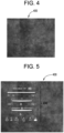
- FIGS. 4 and 5 depict another embodiment of a deadfront article 400 for a vehicle display, such as displays 130, 230 and/or 330.
- a patterned deadfront article 400 is depicted in FIG. 4 .
- a light source of the associated display is inactive as in FIG. 4 , only the pattern of the deadfront article 400 can be seen.
- the light source of the associated display is active and icons 430 can be seen through the deadfront article 400.
- icons 430 disappear, and deadfront article 400 presents a surface showing a desired pattern (e.g., a leather grain pattern in FIG. 4 ) that is unbroken by icons 430.
- deadfront article 400 provides this differential icon display by utilizing one or more colored layers disposed between an outer substrate and a light source.
- the optical properties of the colored layers are designed such that when the light source is turned off the borders of the icons or other display structures beneath the colored layer are not visible, but when the light source is on, graphics 410 and/or icons 430 are visible.
- the deadfront articles discussed herein are designed to provide a high quality deadfront appearance, including high contrast icons with the light source on, combined with a uniform deadfront appearance when the light is off. Further, Applicant provides these various deadfront articles with materials suitable for cold forming to curved shapes, including complex curved shapes, as discussed below.
- the deadfront article 400 includes at least a substrate 450, a semi-transparent layer 460, and a contrast layer 470.
- the substrate 450 has an outer surface 480 facing a viewer and an inner surface 490 upon which the semi-transparent layer 460 and/or the contrast layer 470 are, at least in part, disposed.
- the term "dispose" includes coating, depositing and/or forming a material onto a surface using any known method in the art.
- the disposed material may constitute a layer, as defined herein.
- the phrase "disposed on” includes the instance of forming a material onto a surface such that the material is in direct contact with the surface and also includes the instance where the material is formed on a surface, with one or more intervening material(s) is between the disposed material and the surface.
- the intervening material(s) may constitute a layer, as defined herein.
- the term "layer” may include a single layer or may include one or more sub-layers. Such sub-layers may be in direct contact with one another. The sub-layers may be formed from the same material or two or more different materials. In one or more alternative embodiments, such sub-layers may have intervening layers of different materials disposed therebetween.
- a layer may include one or more contiguous and uninterrupted layers and/or one or more discontinuous and interrupted layers (i.e., a layer having different materials formed adjacent to one another).
- a layer or sub-layers may be formed by any known method in the art, including discrete deposition or continuous deposition processes. In one or more embodiments, the layer may be formed using only continuous deposition processes, or, alternatively, only discrete deposition processes. While the specifics of the substrate 450 will be discussed in greater detail below, in embodiments the substrate 450 has a thickness of from 0.05 to 2.0 mm. In one or more embodiments, the substrate may be a transparent plastic, such as PMMA, polycarbonate and the like, or may include glass material (which may be optionally strengthened).
- the semi-transparent layer 460 is printed onto at least a portion of the inner surface 490 of the substrate 450.
- the semi-transparent layer 460 is deposited using non-conductive vacuum metallization.
- the contrast layer 470 is printed onto at least a portion of the inner surface 490 of the substrate 450 and/or onto at least a portion of the semi-transparent layer 460.
- the deadfront article 400 also includes a functional surface layer 500 and/or an opaque layer 510 (also referred to as "high optical density layer").
- the functional surface layer 500 can be configured to provide one or more of a variety of functions.
- the functional surface layer 500 is an optical coating configured to provide easy-to-clean performance, anti-glare properties, anti-reflection properties, and/or half-mirror coating. Such optical coatings can be created using single layers or multiple layers. In the case of anti-reflection functional surface layers, such layers may be formed using multiple, layers having alternating high refractive index and low refractive index.
- Non-limiting examples of low-refractive index materials include SiO 2 , MgF 2 , and Al 2 O 3
- non-limiting examples of high-refractive index materials include Nb 2 O 5 , TiO 2 , ZrO 2 , HfO 2 , and Y 2 O 3
- the total thickness of such an optical coating (which may be disposed over an anti-glare surface or a smooth substrate surface) is from 5 nm to 750 nm.
- the functional surface layer 500 that provides easy-to-clean performance provides enhanced feel for touch screens and/or coating/treatments to reduce fingerprints.
- functional surface layer 500 is integral to the first surface of the substrate.
- such functional surface layers can include an etched surface in the first surface of the substrate 450 providing an anti-glare surface (or haze of from, e.g., 2% to 20%).
- the opaque layer 510 has high optical density in order to block light transmittance.
- “opaque layer” is used interchangeably with “high optical density layer.”
- the opaque layer 510 is used to block light from transmitting through certain regions of the deadfront article 400.
- the opaque layer 510 obscures functional or non-decorative elements provided for the operation of the deadfront article 400.
- the opaque layer 510 is provided to outline backlit icons and/or other graphics (such as the graphic 410 and/or power button 420 shown in FIGS. 2 and 3 and the icons 430 shown in FIG. 5 ) to increase the contrast at the edges of such icons and/or graphics.
- the opaque layer 510 has interruptions in the layer that define a window for the graphic(s) 410, power button(s) 420, and/or icon(s) 430. That is, in embodiments, the opaque layer 510 extends continuously until an edge of a perimeter for a graphic 410, power button 420, and/or icon 430 is reached. At such a perimeter edge, the opaque layer 510 stops, or in some embodiments, substantially decreases in optical density (e.g., thins in material thickness, decreases in material density, etc.).
- the opaque layer 510 resumes intermittently in the region of the graphic 410, power button 420, and/or icon 430 to define features of the graphic 410, power button 420, and/or icon 430, such as to define the "
- the opaque layer 510 can be any color; in particular embodiments, though, the opaque layer 510 is black or gray.
- the opaque layer 510 is applied via screen printing or inkjet printing over the semi-transparent layer 460 and/or over the inner surface 490 of the substrate 450.
- the thickness of an inkjet-printed opaque layer 510 is from 1 ⁇ m to 5 ⁇ m
- the thickness of a screen-printed opaque layer 510 is from 5 ⁇ m to 20 ⁇ m.
- a printed opaque layer 510 can have a thickness in the range of from 1 ⁇ m to 20 ⁇ m.
- the opaque layer 510 is a metal layer deposited via physical vapor deposition and/or is an optical stack produced using the high/low-index stacking discussed above for color matching.
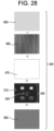
- FIG. 28 provides an exploded view of the layers comprising the deadfront article 400 in an embodiment.
- the layers include the substrate 450, the semi-transparent layer 460, the contrast layer 470, the opaque layer 510, and a color layer 650.
- the semi-transparent layer 460 is a woodgrain pattern
- the opaque layer 510 provides negative images for icons 430, e.g., for an entertainment console, such as a power button 420, tuning controls, volume control, presets, etc.
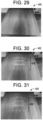
- the combination of the semi-transparent layer 460, the contrast layer 470, and the opaque layer 510 provide a deadfront article 400 such as is shown in FIGS. 29 and 30 .
- FIG. 29 and 30 In FIG.
- the woodgrain of the semi-transparent layer 460 is seen when the deadfront article 400 is not backlit, and when the deadfront article 400 is backlit, the icons 430 are visible through the outer surface 480 of the deadfront article 400.
- the color layer 650 when the color layer 650 is disposed on the opaque layer 510 (at least in the regions of the icons 430) the color of the icons 430 can be changed as shown in FIG. 31 .
- the color layer 650 can include multiple colors across the layer as shown in FIG. 31 and/or specific colors in regions of specific icons 430 or portions of icons 430.
- the color layer 650 is a continuous layer in some embodiments, and in other embodiments, the color layer 650 is discontinuous, i.e., color is only provided in certain locations over the opaque layer 510 and/or contrast layer 470 in regions that define the icons 430.
- the optical densities of the layers are tailored to enhance the visibility of the graphics 410, power button 420, and/or icons 430 when the deadfront article 400 is backlit.
- the combined optical density of the semi-transparent layer 460 and the contrast layer 470 in illuminated regions is from 1.0 to 2.1.
- the combined optical density is 1.2 to 1.6, and in still other embodiments, the combined optical density is about 1.4.
- the optical density of the contrast layer 470 is from 0.9 to 2.0 in embodiments
- the optical density of the semi-transparent layer 460 is 0.1 to 0.5 in embodiments.
- the combined optical density of the semi-transparent layer 460, the contrast layer 470, and the opaque layer 510 is at least 3.4.
- the optical density of the contrast layer 470 is from 0.9 to 2.0 in embodiments
- the optical density of the semi-transparent layer 460 is from 0.1 to 0.5 in embodiments
- the optical density of the opaque layer 510 is at least 2.4 in embodiments.
- the optical density of the color layer 650 is from 0.3 to 0.7.
- the optical density of a particular layer can vary across the layer to provide enhanced contrast or to conserve the ink or material comprising the layer.
- the optical density of the contrast layer 470 can be lower in illuminated regions than in non-illuminated regions.
- the optical density of the color layer 650 can be lower (or zero) in non-illuminated regions than in illuminated regions.
- FIGS. 32 and 33 and FIGS. 34 and 35 show different deadfront articles having different levels of optical density, and thus, these figures demonstrate the different appearance between deadfront articles 400 in which the optical density is too high in the illuminated regions ( FIGS. 32 and 33 ) and in which the optical density is within the above-described ranges for the illuminated regions ( FIGS. 34 and 35 ).
- the deadfront article has a carbon fiber pattern in which the optical density of the semi-transparent layer is too high.
- the illuminated region is obscured.
- the center icon 430 is a power button 420 that has been provided with a red color using a color layer 650.
- the deadfront article 400 is placed over or in front of a display 530.
- the display may include a touch-enabled displays which include a display and touch panel.
- Exemplary displays include LED displays ( FIG. 8 ), a DLP MEMS chip ( FIG. 9 ), LCDs, OLEDs, transmissive displays, reflective displays and the like.
- the display 530 is affixed or mounted to the deadfront article 400 using, e.g., an optically clear adhesive 540.
- the deadfront article 400 has a transmittance from about 5% to 30% along the visible spectrum, i.e., a wavelength from 400 nm to 700 nm.
- the deadfront article 400 exhibits an average light transmittance in a range from about 5% to about 30% along the entire wavelength range from about 400 nm to about 700 nm.
- transmittance is defined as the percentage of incident optical power within a given wavelength range transmitted through a material (e.g., the deadfront article, the substrate or the layers thereof).
- the deadfront article 400 is a low transmittance deadfront article in which light transmission is 10% or less over the entire visible spectrum.
- the opaque layer 510 may not be necessary to obscure the edges of the display 530, i.e., non-display regions, such as a display border, and/or wiring, connectors, etc.
- the deadfront article 400 is a high transmittance deadfront article exhibiting an average transmittance from about 10% to about 30%. In such embodiments, the opaque layer 510 may be necessary to block non-display regions from being seen.
- the deadfront article 400 is provided with touch functionality as shown in FIG. 10 .
- the deadfront article 400 includes substrate 450, a black semi-transparent layer 460, and a contrast layer 470 that is disposed on portions of the substrate 450 and of the semi-transparent layer 460.
- the contrast layer 470 and the semi-transparent layer 460 define an icon or a graphic, such as a power button 420 (e.g., as shown in FIGS. 2 and 3 ).
- touch functionality is provided by capacitive sensing.
- the capacitive sensor is created by a transparent conductive film or coating 550.
- the transparent conductive film 550 is a transparent conductive oxide (e.g., indium-tin-oxide (ITO)) coated polyester (e.g., PET) film.
- ITO indium-tin-oxide
- a light source 570 Upon activation of a toggle switch (e.g., by touching the deadfront article 400 in the region of the transparent conductive film 550), a light source 570 is activated or deactivated 570.
- the light source 570 includes a red LED 580 and a green LED 590.
- the red LED 580 and green LED 590 indicate the status of the deadfront article 400. For example, prior to turning the vehicle on, both the red LED 580 and green LED 590 are off as shown at the bottom of the legend of the power button 420 states on the left of FIG. 10 .
- the red LED 580 is on while the green LED 590 is off (top of the legend of power button 420 states), signifying that the display 530 is inactive.
- the toggle switch 560 will turn off the red LED 580, turn on the green LED 590, and activate the display 530. If the user desires to inactivate the display 530 while the vehicle is still on, the user can again touch the power button 420, and the toggle switch 560 will turn off the green LED 590, turn on the red LED 580, and shut off the display 530.
- a vibration motor 600 is provided to provide haptic feedback each time the toggle switch 560 is activated.
- the touch-functionality is suitable for other features.
- the touch-functionality is suitable for use in controlling a variety of vehicle systems, such as climate control (i.e., heating and air conditioning) systems, radio/entertainment systems, dashboard display panels (for, e.g., speedometer, odometer, trip odometer, tachometer, vehicle warning indicators, etc.), and center console display panels (for, e.g., GPS displays, in-vehicle information, etc.), among others.
- the deadfront article 400 is depicted with a speedometer 610 and climate controls 620.
- the deadfront 400 article includes a leather grain pattern.
- FIG. 12 provides a substantially similar deadfront article 400 with a speedometer 610 and climate controls 620, but the deadfront 400 includes a wood grain pattern.
- the substrate 450 is treated (e.g., via sandblasting, etching, engraving, etc.) in the area of a button to provide tactile feedback to a user's finger.
- the toggle switch 560 is provided with a delay of, e.g., one to three seconds so as to avoid accidental activation of the toggle switch 560.
- FIG. 36 provides another embodiment of a deadfront article 400 with touch functionality.
- the deadfront article 400 includes a touch panel 660.
- the touch panel 660 can be any of a variety of suitable touch panels, such as a resistive touch panel, a capacitive (e.g., surface or projected) touch panel, a surface acoustic wave touch panel, an infrared touch panel, an optical imaging touch panel, dispersive signal touch panel, or an acoustic pulse recognition touch panel.
- the touch panel 660 is laminated to the deadfront article 400 using an optically clear adhesive 540.
- the touch panel 660 is printed onto the deadfront article 400 such that the optically clear adhesive 540 is unnecessary.
- the touch panel 660 is cold bendable to provide a three-dimensional shape. Cold bending of the deadfront article 400 (including the touch panel 660) is described in greater detail further below.
- the semi-transparent layer 460 and the contrast layer 470 are disposed on the substrate 450.
- the semi-transparent layer 460 is printed onto the substrate using a CMYK color model.
- the contrast layer is not white, such as gray
- the CMYK color model can also be used to print the contrast layer 470.
- color models that incorporate white ink can be used for printing the contrast layer 470.
- the printed semi-transparent layer 460 and the printed contrast layer 470 each have a thickness of from 1 ⁇ m to 6 ⁇ m.
- the color layer 650 also has a thickness of from 1 ⁇ m to 6 ⁇ m. In embodiments, the contrast layer 470 has a thickness of from 1 ⁇ m to 14 ⁇ m. Further, in embodiments, the color layer 650 is printed onto the opaque layer 510 and/or the contrast layer 470. In certain embodiments, the color layer 650 is printed onto the opaque layer 510 and/or contrast layer 470 using the CMYK color model.
- the ink used for printing the semi-transparent layer 460, the contrast layer 470, and/or the color layer 650 can be thermal or UV cured ink.
- the ink is composed of at least one or more colorants and a vehicle.
- the colorants can be soluble or insoluble in the vehicle.
- the colorants are dry colorants in the form of a fine powder. Such fine powders have particles that are, in embodiments, from 10 nm to 500 nm in size.
- the colorant provides cyan, magenta, yellow, and/or key (black) colors.
- the colorant can be any of a variety of suitable pigments, such as TiO 2 , Sb 2 O 3 , BaSO 4 , BaSO4:ZnS, ZnO, and (PbCO 3 ) 2 :Pb(OH) 2 .
- suitable pigments such as TiO 2 , Sb 2 O 3 , BaSO 4 , BaSO4:ZnS, ZnO, and (PbCO 3 ) 2 :Pb(OH) 2 .
- the colorants are dissolved or suspended in the vehicle.
- the vehicle can serve as a binder to create adhesion to the surface upon which the ink is applied.
- additives are included in the vehicle specifically for the purpose of improving adhesion to glass/plastic surfaces.
- vehicles for the colorant include propylene glycol monomethyl ether, diethylene glycol diethyl ether, dimethylacetamide, and toluene. Generally, such vehicles solidify at temperatures from 80 °C to 200 °C.
- the ink includes from 0.5% - 6% by volume of the colorant and 94% - 99.5% by volume of the vehicle.
- a leather grain semi-transparent layer 460 was printed on to the substrate 450, specifically using an inkjet printer according to a CMYK color model (although, in other embodiments, other printer types and/or printing models are used).
- a white contrast layer 470 was printed behind the semi-transparent layer 460.
- FIGS. 13B and 14B depict the back sides of these printed layers.
- the contrast of the leather grain pattern of the semi-transparent layer 460 is enhanced by the white contrast layer 470 in FIG. 14A .
- the overall appearance of the pattern or design in the semi-transparent layer 460 is brighter, and the contrast between the colors in the pattern or design is enhanced.
- FIG. 15 depicts contrast layers 470 printed over a glass background.
- the contrast layers 470 are of varying whiteness (W).
- W whiteness
- "Whiteness” as used herein refers to the CIE whiteness, or ISO 11475:2004, which measures the amount of light reflected by a white surface over the visible spectrum (wavelength of 400 nm to 700 nm).
- the lower left corner of FIG. 15 is a contrast layer of 100W.
- the whiteness of the contrast layer 470 decreases from 100W to 60W going left to right along the bottom row, and along the top row, whiteness decreases from 50W to 10W going left to right.
- relatively lower whiteness contrast layers 470 transmit more light than relatively higher whiteness contrast layer 470.
- the data for generating the graph of FIG. 16 was calculated after printing white ink having diethylene glycol diethyl ether solvent and using a 128 nozzle, 40 pL printhead.
- the transmittance (T) is controlled through manipulation of printing resolution and layer thickness.
- the deadfront article 400 is provided with a contrast layer 470 having a whiteness of between 10W and 60W. In other embodiments, the contrast layer 470 has a whiteness of between 20W and 50W. In a particular embodiment, the contrast layer 470 has a whiteness of between 20W and 30W.
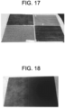
- FIG. 17 depicts four glass substrates 450 having a semi-transparent layer 460 and contrast layer 470 printed thereon.
- the semi-transparent layers 460 feature designs of a knitted fabric pattern, a leather grain pattern, and two wood grain patterns.
- FIG. 18 depicts a semi-transparent layer 460 that transitions from a leather grain pattern to a solid black pattern.
- a green power button is also printed in the lower left corner.
- FIGS. 19 and 20 provide a comparison between the same knitted fabric pattern semi-transparent layer 460.
- a contrast layer 470 was printed behind the semi-transparent layer 460.
- the deadfront article 400 has a transmittance of between 5% and 10% over the visible spectrum (wavelength of 400 nm to 700 nm).
- FIGS. 21 and 22 depict a marble deadfront article 400.
- FIG. 21 is the viewer side of the deadfront article 400
- FIG. 22 is the rear side of the deadfront article 400.
- a section of the semi-transparent layer 460 is not covered with the contrast layer 470.
- a display could be mounted to the section not covered by the contrast layer 470.
- deadfront article 2000 may be any of the deadfront embodiments discussed herein.
- deadfront article 2000 includes a curved outer glass substrate 2010 having at least a first radius of curvature, R1, and in various embodiments, curved outer glass substrate 2010 is a complex curved sheet of glass material having at least one additional radius of curvature.
- R1 is in a range from about 60 mm to about 1500 mm.
- Curved deadfront article 2000 includes a deadfront colored layer 2020 (e.g., the ink/pigment layer(s), as discussed above) located along an inner, major surface of curved outer glass substrate 2010.
- deadfront colored layer 2020 is printed, colored, shaped, etc. to provide a wood-grain design, a leather-grain design, a fabric design, a brushed metal design, a graphic design, a solid color and/or a logo.
- embodiments of the invention are not limited to these designs or patterns.
- Curved deadfront article 2000 also may include any of the additional layers 2030 (e.g., high optical density layers, light guide layers, reflector layers, display module(s), display stack layers, light sources, touch panels, etc.) as discussed above or that otherwise may be associated with a display or vehicle interior system as discussed herein.
- additional layers 2030 e.g., high optical density layers, light guide layers, reflector layers, display module(s), display stack layers, light sources, touch panels, etc.
- curved deadfront article 2000 including glass substrate 2010 and colored layer 2020 may be cold-formed together to a curved shape, as shown in FIG. 23 .
- curved deadfront 2000 including glass substrate 2010, colored layer 2020 and additional layers 2030 may be cold-formed together to a curved shape, such as that shown in FIG. 23 .
- glass substrate 2010 may be formed to a curved shape, and then layers 2020 and 2030 are applied following curve formation.
- outer glass substrate 2010 is shown prior to being formed to the curved shape shown in FIG. 24 .
- Applicant believes that the articles and processes discussed herein provide high quality deadfront articles utilizing glass of sizes, shapes, compositions, strengths, etc. not previously provided.
- outer glass substrate 2010 includes a first major surface 2050 and a second major surface 2060 opposite first major surface 2050.
- An edge surface or minor surface 2070 connects the first major surface 2050 and the second major surface 2060.
- Outer glass substrate 2010 has a thickness (t) that is substantially constant and is defined as a distance between the first major surface 2050 and the second major surface 2060.
- the thickness (t) as used herein refers to the maximum thickness of the outer glass substrate 2010.
- Outer glass substrate 2010 includes a width (W) defined as a first maximum dimension of one of the first or second major surfaces orthogonal to the thickness (t), and outer glass substrate 2010 also includes a length (L) defined as a second maximum dimension of one of the first or second surfaces orthogonal to both the thickness and the width.
- W width
- L length
- the dimensions discussed herein are average dimensions.
- outer glass substrate 2010 has a thickness (t) that is in a range from 0.05 mm to 2 mm. In various embodiments, outer glass substrate 2010 has a thickness (t) that is about 1.5 mm or less.
- the thickness may be in a range from about 0.1 mm to about 1.5 mm, from about 0.15 mm to about 1.5 mm, from about 0.2 mm to about 1.5 mm, from about 0.25 mm to about 1.5 mm, from about 0.3 mm to about 1.5 mm, from about 0.35 mm to about 1.5 mm, from about 0.4 mm to about 1.5 mm, from about 0.45 mm to about 1.5 mm, from about 0.5 mm to about 1.5 mm, from about 0.55 mm to about 1.5 mm, from about 0.6 mm to about 1.5 mm, from about 0.65 mm to about 1.5 mm, from about 0.7 mm to about 1.5 mm, from about 0.1 mm to about 1.4 mm, from about 0.1 mm to about 1.3 mm, from about 0.1 mm to about 1.5
- outer glass substrate 2010 has a width (W) in a range from about 5 cm to about 250 cm, from about 10 cm to about 250 cm, from about 15 cm to about 250 cm, from about 20 cm to about 250 cm, from about 25 cm to about 250 cm, from about 30 cm to about 250 cm, from about 35 cm to about 250 cm, from about 40 cm to about 250 cm, from about 45 cm to about 250 cm, from about 50 cm to about 250 cm, from about 55 cm to about 250 cm, from about 60 cm to about 250 cm, from about 65 cm to about 250 cm, from about 70 cm to about 250 cm, from about 75 cm to about 250 cm, from about 80 cm to about 250 cm, from about 85 cm to about 250 cm, from about 90 cm to about 250 cm, from about 95 cm to about 250 cm, from about 100 cm to about 250 cm, from about 110 cm to about 250 cm, from about 120 cm to about 250 cm, from about 130 cm to about 250 cm, from about 140 cm to about 250 cm, from about 150 cm to about 250 cm, from about 5 cm to about 240
- outer glass substrate 2010 has a length (L) in a range from about 5 cm to about 250 cm, from about 10 cm to about 250 cm, from about 15 cm to about 250 cm, from about 20 cm to about 250 cm, from about 25 cm to about 250 cm, from about 30 cm to about 250 cm, from about 35 cm to about 250 cm, from about 40 cm to about 250 cm, from about 45 cm to about 250 cm, from about 50 cm to about 250 cm, from about 55 cm to about 250 cm, from about 60 cm to about 250 cm, from about 65 cm to about 250 cm, from about 70 cm to about 250 cm, from about 75 cm to about 250 cm, from about 80 cm to about 250 cm, from about 85 cm to about 250 cm, from about 90 cm to about 250 cm, from about 95 cm to about 250 cm, from about 100 cm to about 250 cm, from about 110 cm to about 250 cm, from about 120 cm to about 250 cm, from about 130 cm to about 250 cm, from about 140 cm to about 250 cm, from about 150 cm to about 250 cm, from about 5 cm to about 240
- outer glass substrate 2010 is shaped to a curved shaping having at least one radius of curvature, shown as R1.
- outer glass substrate 2010 may be shaped to the curved shape via any suitable process, including cold-forming and hot-forming.
- outer glass substrate 2010 is shaped to the curved shape shown in FIG. 23 , either alone, or following attachment of layers 2020 and 2030, via a cold-forming process.
- cold-bent refers to curving the glass substrate at a cold-form temperature which is less than the softening point of the glass (as described herein).
- a feature of a cold-formed glass substrate is an asymmetric surface compressive between the first major surface 2050 and the second major surface 2060. In some embodiments, prior to the cold-forming process or being cold-formed, the respective compressive stresses in the first major surface 2050 and the second major surface 2060 are substantially equal.
- the first major surface 2050 and the second major surface 2060 exhibit no appreciable compressive stress, prior to cold-forming.
- the first major surface 2050 and the second major surface 2060 exhibit substantially equal compressive stress with respect to one another, prior to cold-forming.
- the compressive stress on the second major surface 2060 e.g., the concave surface following bending
- increases i.e., the compressive stress on the second major surface 2050 is greater after cold-forming than before cold-forming).
- the cold-forming process increases the compressive stress of the glass substrate being shaped to compensate for tensile stresses imparted during bending and/or forming operations.
- the cold-forming process causes the second major surface 2060 to experience compressive stresses, while the first major surface 2050 (e.g., the convex surface following bending) experiences tensile stresses.
- the tensile stress experienced by surface 2050 following bending results in a net decrease in surface compressive stress, such that the compressive stress in surface 2050 of a strengthened glass sheet following bending is less than the compressive stress in surface 2050 when the glass sheet is flat.
- first major surface and the second major surface (2050,2060) are already under compressive stress, and thus first major surface 2050 can experience greater tensile stress during bending without risking fracture.
- the thickness of outer glass substrate 2010 is tailored to allow outer glass substrate 2010 to be more flexible to achieve the desired radius of curvature. Moreover, a thinner outer glass substrate 2010 may deform more readily, which could potentially compensate for shape mismatches and gaps that may be created by the shape of a support or frame (as discussed below). In one or more embodiments, a thin and strengthened outer glass substrate 2010 exhibits greater flexibility especially during cold-forming. The greater flexibility of the glass substrate discussed herein may allow for consistent bend formation without heating.
- outer glass substrate 2010 (and consequently deadfront article 2000) may have a compound curve including a major radius and a cross curvature.
- a complexly curved cold-formed outer glass substrate 2010 may have a distinct radius of curvature in two independent directions.
- the complexly curved cold-formed outer glass substrate 2010 may thus be characterized as having "cross curvature," where the cold-formed outer glass substrate 2010 is curved along an axis (i.e., a first axis) that is parallel to a given dimension and also curved along an axis (i.e., a second axis) that is perpendicular to the same dimension.
- the curvature of the cold-formed outer glass substrate 2010 can be even more complex when a significant minimum radius is combined with a significant cross curvature, and/or depth of bend.
- display assembly 2100 is shown according to an exemplary embodiment.
- display assembly 2100 includes frame 2110 supporting (either directly or indirectly) both a light source, shown as a display module 2120, and deadfront article 2000.
- deadfront article 2000 and display module 2120 are coupled to frame 2110, and display module 2120 is positioned to allow a user to view light, images, etc. generated by display module 2120 through deadfront article 2000.
- frame 2110 may be formed from a variety of materials such as plastic (PC/ABS, etc.), metals (Al-alloys, Mg-alloys, Fe-alloys, etc.).
- FIG. 25 shows a light source in the form of a display module
- display assembly 2100 may include any of the light sources discussed herein for producing graphics, icons, images, displays, etc. through any of the dead front embodiments discussed herein.
- frame 2110 is shown as a frame associated with a display assembly, frame 2110 may be any support or frame article associated with a vehicle interior system.
- deadfront article 2000 allows for formation of deadfront article 2000 to conform to a wide variety of curved shapes that frame 2110 may have.
- frame 2110 has a support surface 2130 that has a curved shape
- deadfront article 2000 is shaped to match the curved shape of support surface 2130.
- deadfront structure 2000 may be shaped into a wide variety of shapes to conform to a desired frame shape of a display assembly 2100, which in turn may be shaped to fit the shape of a portion of a vehicle interior system, as discussed herein.
- deadfront structure 2000 (and specifically outer glass substrate 2010) is shaped to have a first radius of curvature, R1, of about 60 mm or greater.
- R1 may be in a range from about 60 mm to about 1500 mm, from about 70 mm to about 1500 mm, from about 80 mm to about 1500 mm, from about 90 mm to about 1500 mm, from about 100 mm to about 1500 mm, from about 120 mm to about 1500 mm, from about 140 mm to about 1500 mm, from about 150 mm to about 1500 mm, from about 160 mm to about 1500 mm, from about 180 mm to about 1500 mm, from about 200 mm to about 1500 mm, from about 220 mm to about 1500 mm, from about 240 mm to about 1500 mm, from about 250 mm to about 1500 mm, from about 260 mm to about 1500 mm, from about 270 mm to about 1500 mm, from about 280 mm to about 1500 mm, from about 290 mm to about 1500
- support surface 2130 has a second radius of curvature of about 60 mm or greater.
- the second radius of curvature of support surface 2130 may be in a range from about 60 mm to about 1500 mm, from about 70 mm to about 1500 mm, from about 80 mm to about 1500 mm, from about 90 mm to about 1500 mm, from about 100 mm to about 1500 mm, from about 120 mm to about 1500 mm, from about 140 mm to about 1500 mm, from about 150 mm to about 1500 mm, from about 160 mm to about 1500 mm, from about 180 mm to about 1500 mm, from about 200 mm to about 1500 mm, from about 220 mm to about 1500 mm, from about 240 mm to about 1500 mm, from about 250 mm to about 1500 mm, from about 260 mm to about 1500 mm, from about 270 mm to about 1500 mm, from about 280 mm to about 1500 mm, from about 290 mm to about 1500 mm, from about
- deadfront structure 2000 is cold-formed to exhibit a first radius curvature, R1, that is within 10% (e.g., about 10% or less, about 9% or less, about 8% or less, about 7% or less, about 6% or less, or about 5% or less) of the second radius of curvature of support surface 2130 of frame 2110.
- R1 first radius curvature
- support surface 2130 of frame 2110 exhibits a radius of curvature of 1000 mm
- deadfront article 2000 is cold-formed to have a radius of curvature in a range from about 900 mm to about 1100 mm.
- first major surface 2050 and/or second major surface 2060 of glass substrate 2010 includes a functional coating layer as described herein.
- the functional coating layer may cover at least a portion of first major surface 2050 and/or second major surface 2060.
- Exemplary functional coatings include at least one of a glare reduction coating or surface, an anti-glare coating or surface, a scratch resistance coating, an anti-reflection coating, a half-mirror coating, or easy-to-clean coating.
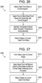
- a method 2200 for forming a display assembly that includes a cold-formed deadfront article, such as deadfront article 2000 is shown.
- the method includes curving a deadfront article, such deadfront article 2000, to a curved surface of a support.
- the support may be a frame of a display, such as frame 2110 that defines a perimeter and curved shape of a vehicle display.
- the frame includes a curved support surface, and one of the major surfaces 2050 and 2060 of deadfront article 2000 is placed into contact with the curved support surface.
- the method includes securing the curved deadfront article to the support causing the deadfront article to bend into conformity (or conform) with the curved surface of the support.
- a curved deadfront article 2000 as shown in FIG. 23 , is formed from a generally flat deadfront article to a curved deadfront article.
- curving the flat deadfront article forms a curved shape on the major surface facing the support, while also causing a corresponding (but complimentary) curve to form in the major surface opposite of the frame. Applicant believes that by bending the deadfront article directly on the curved frame, the need for a separate curved die or mold (typically needed in other glass bending processes) is eliminated.
- the force applied in step 2210 and/or step 2220 may be air pressure applied via a vacuum fixture.
- the air pressure differential is formed by applying a vacuum to an airtight enclosure surrounding the frame and the deadfront article.
- the airtight enclosure is a flexible polymer shell, such as a plastic bag or pouch.
- the air pressure differential is formed by generating increased air pressure around the deadfront article and the frame with an overpressure device, such as an autoclave.
- air pressure provides a consistent and highly uniform bending force (as compared to a contact-based bending method) which further leads to a robust manufacturing process.
- the air pressure differential is between 0.5 and 1.5 atmospheres of pressure (atm), specifically between 0.7 and 1.1 atm, and more specifically is 0.8 to 1 atm.
- the temperature of the deadfront article is maintained below the glass transition temperature of the material of the outer glass layer during steps 2210 and 2220.
- method 2200 is a cold-forming or cold-bending process.
- the temperature of the deadfront article is maintained below 500 degrees C, 400 degrees C, 300 degrees C, 200 degrees C or 100 degrees C.
- the deadfront article is maintained at or below room temperature during bending.
- the deadfront article is not actively heated via a heating element, furnace, oven, etc. during bending, as is the case when hot-forming glass to a curved shape.
- the cold-forming processes discussed herein are believed to generate curved deadfront articles with a variety of properties that are believed to be superior to those achievable via hot-forming processes.
- heating during hot-forming processes decreases optical properties of curved glass substrates, and thus, the curved glass-based deadfront articles formed utilizing the cold-bending processes/systems discussed herein provide for both curved glass shape along with improved optical qualities not believed achievable with hot-bending processes.
- many materials used for the various coatings and layers are applied via deposition processes, such as sputtering processes that are typically ill-suited for coating on to a curved surface.
- many coating materials such as the deadfront ink/pigment materials, also are not able to survive the high temperatures associated with hot-bending processes.
- layer 2020 is applied to outer glass substrate 2010 prior to cold-bending.
- the curved deadfront article is attached or affixed to the curved support.
- the attachment between the curved deadfront article and the curved support may be accomplished via an adhesive material.
- Such adhesives may include any suitable optically clear adhesive for bonding the deadfront article in place relative to the display assembly (e.g., to the frame of the display).
- the adhesive may include an optically clear adhesive available from 3M Corporation under the trade name 8215.
- the thickness of the adhesive may be in a range from about 200 ⁇ m to about 500 ⁇ m.
- the adhesive material may be applied in a variety of ways.
- the adhesive is applied using an applicator gun and made uniform using a roller or a draw down die.
- the adhesives discussed herein are structural adhesives.
- the structural adhesives may include an adhesive selected from one or more of the categories: (a) Toughened Epoxy (Masterbond EP21TDCHT-LO, 3M Scotch Weld Epoxy DP460 Off-white); (b) Flexible Epoxy (Masterbond EP21TDC-2LO, 3M Scotch Weld Epoxy 2216 B/A Gray); (c) Acrylic (LORD Adhesive 410/Accelerator 19 w/ LORD AP 134 primer, LORD Adhesive 852/LORD Accelerator 25GB, Loctite HF8000, Loctite AA4800); (d) Urethanes (3M Scotch Weld Urethane DP640 Brown); and (e) Silicones (Dow Corning 995).
- structural glues available in sheet format may be utilized.
- pressure sensitive structural adhesives such as 3M VHB tapes may be utilized. In such embodiments, utilizing a pressure sensitive adhesive allows for the curved deadfront article to be bonded to the frame without the need for a curing step.
- the method includes step 2240 in which the curved deadfront is secured to a display.
- the method may include securing the display to the deadfront article before step 2210 and curving both the display and the deadfront article in step 2210.
- the method includes disposing or assembling the curved deadfront and display in a vehicle interior system 100, 200, 300.
- the substrate (e.g., outer glass layer 2010) of a deadfront article is formed to curved shape at step 2310. Shaping at step 2310 may be either cold-forming or hot-forming.
- the deadfront ink/pigment layer(s) e.g., layer 2020
- the curved deadfront article is attached to a frame, such as frame 2110 of display assembly 2100, or other frame that may be associated with a vehicle interior system.
- the various substrates of the deadfront articles discussed herein may be formed from any transparent material such as a polymer (e.g., PMMA, polycarbonate and the like) or glass.
- Suitable glass compositions include soda lime glass, aluminosilicate glass, borosilicate glass, boroaluminosilicate glass, alkali-containing aluminosilicate glass, alkali-containing borosilicate glass, and alkali-containing boroaluminosilicate glass.
- the glass compositions disclosed herein are described in mole percent (mol%) as analyzed on an oxide basis.
- the glass composition may include SiO 2 in an amount in a range from about 66 mol% to about 80 mol%, from about 67 mol% to about 80 mol%, from about 68 mol% to about 80 mol%, from about 69 mol% to about 80 mol%, from about 70 mol% to about 80 mol%, from about 72 mol% to about 80 mol%, from about 65 mol% to about 78 mol%, from about 65 mol% to about 76 mol%, from about 65 mol% to about 75 mol%, from about 65 mol% to about 74 mol%, from about 65 mol% to about 72 mol%, or from about 65 mol% to about 70 mol%, and all ranges and sub-ranges therebetween.
- the glass composition includes Al 2 O 3 in an amount greater than about 4 mol%, or greater than about 5 mol%. In one or more embodiments, the glass composition includes Al 2 O 3 in a range from greater than about 7 mol% to about 15 mol%, from greater than about 7 mol% to about 14 mol%, from about 7 mol% to about 13 mol%, from about 4 mol% to about 12 mol%, from about 7 mol% to about 11 mol%, from about 8 mol% to about 15 mol%, from 9 mol% to about 15 mol%, from about 9 mol% to about 15 mol%, from about 10 mol% to about 15 mol%, from about 11 mol% to about 15 mol%, or from about 12 mol% to about 15 mol%, and all ranges and sub-ranges therebetween. In one or more embodiments, the upper limit of Al 2 O 3 may be about 14 mol%, 14.2 mol%, 14.4 mol%, 14.6 mol%, or
- glass layer(s) herein are described as an aluminosilicate glass article or including an aluminosilicate glass composition.
- the glass composition or article formed therefrom includes SiO 2 and Al 2 O 3 and is not a soda lime silicate glass.
- the glass composition or article formed therefrom includes Al 2 O 3 in an amount of about 2 mol% or greater, 2.25 mol% or greater, 2.5 mol% or greater, about 2.75 mol% or greater, about 3 mol% or greater.
- the glass composition comprises B 2 O 3 (e.g., about 0.01 mol% or greater). In one or more embodiments, the glass composition comprises B 2 O 3 in an amount in a range from about 0 mol% to about 5 mol%, from about 0 mol% to about 4 mol%, from about 0 mol% to about 3 mol%, from about 0 mol% to about 2 mol%, from about 0 mol% to about 1 mol%, from about 0 mol% to about 0.5 mol%, from about 0.1 mol% to about 5 mol%, from about 0.1 mol% to about 4 mol%, from about 0.1 mol% to about 3 mol%, from about 0.1 mol% to about 2 mol%, from about 0.1 mol% to about 1 mol%, from about 0.1 mol% to about 0.5 mol%, and all ranges and sub-ranges therebetween. In one or more embodiments, the glass composition is substantially free of B 2 O 3 .
- the phrase "substantially free” with respect to the components of the composition means that the component is not actively or intentionally added to the composition during initial batching, but may be present as an impurity in an amount less than about 0.001 mol%.
- the glass composition optionally comprises P 2 O 5 (e.g., about 0.01 mol% or greater). In one or more embodiments, the glass composition comprises a non-zero amount of P 2 O 5 up to and including 2 mol%, 1.5 mol%, 1 mol%, or 0.5 mol%. In one or more embodiments, the glass composition is substantially free of PzOs.
- the glass composition may include a total amount of R 2 O (which is the total amount of alkali metal oxide such as Li 2 O, Na 2 O, K 2 O, Rb 2 O, and CszO) that is greater than or equal to about 8 mol%, greater than or equal to about 10 mol%, or greater than or equal to about 12 mol%.
- R 2 O which is the total amount of alkali metal oxide such as Li 2 O, Na 2 O, K 2 O, Rb 2 O, and CszO
- the glass composition includes a total amount of R 2 O in a range from about 8 mol% to about 20 mol%, from about 8 mol% to about 18 mol%, from about 8 mol% to about 16 mol%, from about 8 mol% to about 14 mol%, from about 8 mol% to about 12 mol%, from about 9 mol% to about 20 mol%, from about 10 mol% to about 20 mol%, from about 11 mol% to about 20 mol%, from about 12 mol% to about 20 mol%, from about 13 mol% to about 20 mol%, from about 10 mol% to about 14 mol%, or from 11 mol% to about 13 mol%, and all ranges and sub-ranges therebetween.
- the glass composition may be substantially free of Rb 2 O, Cs 2 O or both Rb 2 O and Cs 2 O.
- the R 2 O may include the total amount of Li 2 O, Na 2 O and K 2 O only.
- the glass composition may comprise at least one alkali metal oxide selected from Li 2 O, Na 2 O and K 2 O, wherein the alkali metal oxide is present in an amount greater than about 8 mol% or greater.
- the glass composition comprises Na 2 O in an amount greater than or equal to about 8 mol%, greater than or equal to about 10 mol%, or greater than or equal to about 12 mol%.
- the composition includes Na 2 O in a range from about from about 8 mol% to about 20 mol%, from about 8 mol% to about 18 mol%, from about 8 mol% to about 16 mol%, from about 8 mol% to about 14 mol%, from about 8 mol% to about 12 mol%, from about 9 mol% to about 20 mol%, from about 10 mol% to about 20 mol%, from about 11 mol% to about 20 mol%, from about 12 mol% to about 20 mol%, from about 13 mol% to about 20 mol%, from about 10 mol% to about 14 mol%, or from 11 mol% to about 16 mol%, and all ranges and sub-ranges therebetween.
- the glass composition includes less than about 4 mol% K 2 O, less than about 3 mol% K 2 O, or less than about 1 mol% K 2 O.
- the glass composition may include K 2 O in an amount in a range from about 0 mol% to about 4 mol%, from about 0 mol% to about 3.5 mol%, from about 0 mol% to about 3 mol%, from about 0 mol% to about 2.5 mol%, from about 0 mol% to about 2 mol%, from about 0 mol% to about 1.5 mol%, from about 0 mol% to about 1 mol%, from about 0 mol% to about 0.5 mol%, from about 0 mol% to about 0.2 mol%, from about 0 mol% to about 0.1 mol%, from about 0.5 mol% to about 4 mol%, from about 0.5 mol% to about 3.5 mol%, from about 0.5 mol% to about 3 mol%, from about 0.5
- the glass composition is substantially free of Li 2 O.
- the amount of Na 2 O in the composition may be greater than the amount of Li 2 O. In some instances, the amount of Na 2 O may be greater than the combined amount of Li 2 O and K 2 O. In one or more alternative embodiments, the amount of Li 2 O in the composition may be greater than the amount of Na 2 O or the combined amount of Na 2 O and K 2 O.
- the glass composition may include a total amount of RO (which is the total amount of alkaline earth metal oxide such as CaO, MgO, BaO, ZnO and SrO) in a range from about 0 mol% to about 2 mol%. In some embodiments, the glass composition includes a non-zero amount of RO up to about 2 mol%.
- RO alkaline earth metal oxide
- the glass composition comprises RO in an amount from about 0 mol% to about 1.8 mol%, from about 0 mol% to about 1.6 mol%, from about 0 mol% to about 1.5 mol%, from about 0 mol% to about 1.4 mol%, from about 0 mol% to about 1.2 mol%, from about 0 mol% to about 1 mol%, from about 0 mol% to about 0.8 mol%, from about 0 mol% to about 0.5 mol%, and all ranges and sub-ranges therebetween.
- the glass composition includes CaO in an amount less than about 1 mol%, less than about 0.8 mol%, or less than about 0.5 mol%. In one or more embodiments, the glass composition is substantially free of CaO.
- the glass composition comprises MgO in an amount from about 0 mol% to about 7 mol%, from about 0 mol% to about 6 mol%, from about 0 mol% to about 5 mol%, from about 0 mol% to about 4 mol%, from about 0.1 mol% to about 7 mol%, from about 0.1 mol% to about 6 mol%, from about 0.1 mol% to about 5 mol%, from about 0.1 mol% to about 4 mol%, from about 1 mol% to about 7 mol%, from about 2 mol% to about 6 mol%, or from about 3 mol% to about 6 mol%, and all ranges and sub-ranges therebetween.
- the glass composition comprises ZrO 2 in an amount equal to or less than about 0.2 mol%, less than about 0.18 mol%, less than about 0.16 mol%, less than about 0.15 mol%, less than about 0.14 mol%, less than about 0.12 mol%.
- the glass composition comprises ZrO 2 in a range from about 0.01 mol% to about 0.2 mol%, from about 0.01 mol% to about 0.18 mol%, from about 0.01 mol% to about 0.16 mol%, from about 0.01 mol% to about 0.15 mol%, from about 0.01 mol% to about 0.14 mol%, from about 0.01 mol% to about 0.12 mol%, or from about 0.01 mol% to about 0.10 mol%, and all ranges and sub-ranges therebetween.
- the glass composition comprises SnO 2 in an amount equal to or less than about 0.2 mol%, less than about 0.18 mol%, less than about 0.16 mol%, less than about 0.15 mol%, less than about 0.14 mol%, less than about 0.12 mol%.
- the glass composition comprises SnO2 in a range from about 0.01 mol% to about 0.2 mol%, from about 0.01 mol% to about 0.18 mol%, from about 0.01 mol% to about 0.16 mol%, from about 0.01 mol% to about 0.15 mol%, from about 0.01 mol% to about 0.14 mol%, from about 0.01 mol% to about 0.12 mol%, or from about 0.01 mol% to about 0.10 mol%, and all ranges and sub-ranges therebetween.
- the glass composition may include an oxide that imparts a color or tint to the glass articles.
- the glass composition includes an oxide that prevents discoloration of the glass article when the glass article is exposed to ultraviolet radiation.
- oxides include, without limitation oxides of: Ti, V, Cr, Mn, Fe, Co, Ni, Cu, Ce, W, and Mo.
- the glass composition includes Fe expressed as Fe 2 O 3 , wherein Fe is present in an amount up to (and including) about 1 mol%. In some embodiments, the glass composition is substantially free of Fe. In one or more embodiments, the glass composition comprises Fe 2 O 3 in an amount equal to or less than about 0.2 mol%, less than about 0.18 mol%, less than about 0.16 mol%, less than about 0.15 mol%, less than about 0.14 mol%, less than about 0.12 mol%.
- the glass composition comprises Fe 2 O 3 in a range from about 0.01 mol% to about 0.2 mol%, from about 0.01 mol% to about 0.18 mol%, from about 0.01 mol% to about 0.16 mol%, from about 0.01 mol% to about 0.15 mol%, from about 0.01 mol% to about 0.14 mol%, from about 0.01 mol% to about 0.12 mol%, or from about 0.01 mol% to about 0.10 mol%, and all ranges and sub-ranges therebetween.
- TiO 2 may be present in an amount of about 5 mol% or less, about 2.5 mol% or less, about 2 mol% or less or about 1 mol% or less. In one or more embodiments, the glass composition may be substantially free of TiO 2 .
- An exemplary glass composition includes SiO 2 in an amount in a range from about 65 mol% to about 75 mol%, Al 2 O 3 in an amount in a range from about 8 mol% to about 14 mol%, Na 2 O in an amount in a range from about 12 mol% to about 17 mol%, K 2 O in an amount in a range of about 0 mol% to about 0.2 mol%, and MgO in an amount in a range from about 1. 5 mol% to about 6 mol%.
- SnO 2 may be included in the amounts otherwise disclosed herein.
- the substrate includes a glass material (such as outer glass substrate 2010 or other glass substrate) of any of the deadfront article embodiments discussed herein.
- a glass material such as outer glass substrate 2010 or other glass substrate
- such glass substrates may be strengthened.
- the glass substrate may be strengthened to include compressive stress that extends from a surface to a depth of compression (DOC). The compressive stress regions are balanced by a central portion exhibiting a tensile stress. At the DOC, the stress crosses from a positive (compressive) stress to a negative (tensile) stress.
- DOC depth of compression
- the glass substrates used in the deadfront articles discussed herein may be strengthened mechanically by utilizing a mismatch of the coefficient of thermal expansion between portions of the glass to create a compressive stress region and a central region exhibiting a tensile stress.
- the glass substrate may be strengthened thermally by heating the glass to a temperature above the glass transition point and then rapidly quenching.
- the glass substrate used in the deadfront articles discussed herein may be chemically strengthening by ion exchange.
- ions at or near the surface of the glass substrate are replaced by - or exchanged with - larger ions having the same valence or oxidation state.
- ions in the surface layer of the article and the larger ions are monovalent alkali metal cations, such as Li + , Na + , K + , Rb + , and Cs + .
- monovalent cations in the surface layer may be replaced with monovalent cations other than alkali metal cations, such as Ag + or the like.
- the monovalent ions (or cations) exchanged into the glass substrate generate a stress.
- Ion exchange processes are typically carried out by immersing a glass substrate in a molten salt bath (or two or more molten salt baths) containing the larger ions to be exchanged with the smaller ions in the glass substrate.
- a molten salt bath or two or more molten salt baths
- aqueous salt baths may also be utilized.
- the composition of the bath(s) may include more than one type of larger ion (e.g., Na+ and K+) or a single larger ion.
- parameters for the ion exchange process including, but not limited to, bath composition and temperature, immersion time, the number of immersions of the glass substrate in a salt bath (or baths), use of multiple salt baths, additional steps such as annealing, washing, and the like, are generally determined by the composition of the glass substrate (including the structure of the substrate and any crystalline phases present) and the desired DOC and CS of the substrate that results from strengthening.
- Exemplary molten bath composition may include nitrates, sulfates, and chlorides of the larger alkali metal ion.
- Typical nitrates include KNO 3 , NaNO 3 , LiNO 3 , NaSO 4 and combinations thereof.
- the temperature of the molten salt bath typically is in a range from about 380°C up to about 450°C, while immersion times range from about 15 minutes up to about 100 hours depending on the glass thickness, bath temperature and glass (or monovalent ion) diffusivity. However, temperatures and immersion times different from those described above may also be used.
- the glass substrate used to in the deadfront articles may be immersed in a molten salt bath of 100% NaNO 3 , 100% KNO 3 , or a combination of NaNO 3 and KNO 3 having a temperature from about 370 °C to about 480 °C.
- the glass substrate of a deadfront article may be immersed in a molten mixed salt bath including from about 5% to about 90% KNO 3 and from about 10% to about 95% NaNO 3 .
- the glass substrate may be immersed in a second bath, after immersion in a first bath.
- the first and second baths may have different compositions and/or temperatures from one another.
- the immersion times in the first and second baths may vary. For example, immersion in the first bath may be longer than the immersion in the second bath.
- the glass substrate used to form the deadfront articles may be immersed in a molten, mixed salt bath including NaNO 3 and KNO 3 (e.g., 49%/51%, 50%/50%, 51%/49%) having a temperature less than about 420 °C (e.g., about 400 °C or about 380 °C). for less than about 5 hours, or even about 4 hours or less.
- a molten, mixed salt bath including NaNO 3 and KNO 3 (e.g., 49%/51%, 50%/50%, 51%/49%) having a temperature less than about 420 °C (e.g., about 400 °C or about 380 °C). for less than about 5 hours, or even about 4 hours or less.
- Ion exchange conditions can be tailored to provide a "spike” or to increase the slope of the stress profile at or near the surface of the resulting glass substrate of a deadfront article.
- the spike may result in a greater surface CS value.
- This spike can be achieved by single bath or multiple baths, with the bath(s) having a single composition or mixed composition, due to the unique properties of the glass compositions used in the glass substrate of a deadfront article described herein.
- the different monovalent ions may exchange to different depths within the glass substrate (and generate different magnitudes stresses within the glass substrate at different depths).
- the resulting relative depths of the stress-generating ions can be determined and cause different characteristics of the stress profile.
- CS is measured using those means known in the art, such as by surface stress meter (FSM) using commercially available instruments such as the FSM-6000, manufactured by Orihara Industrial Co., Ltd. (Japan).
- FSM surface stress meter
- FSM-6000 manufactured by Orihara Industrial Co., Ltd. (Japan).
- SOC stress optical coefficient
- SOC fiber and four-point bend methods, both of which are described in ASTM standard C770-98 (2013), entitled “Standard Test Method for Measurement of Glass Stress-Optical Coefficient," and a bulk cylinder method.
- CS may be the "maximum compressive stress" which is the highest compressive stress value measured within the compressive stress layer. In some embodiments, the maximum compressive stress is located at the surface of the glass substrate. In other embodiments, the maximum compressive stress may occur at a depth below the surface, giving the compressive profile the appearance of a "buried peak.”
- DOC may be measured by FSM or by a scattered light polariscope (SCALP) (such as the SCALP-04 scattered light polariscope available from Glasstress Ltd., located in Tallinn Estonia), depending on the strengthening method and conditions.
- SCALP scattered light polariscope
- FSM or SCALP may be used depending on which ion is exchanged into the glass substrate.
- FSM is used to measure DOC.
- SCALP is used to measure DOC.
- the DOC is measured by SCALP, since it is believed the exchange depth of sodium indicates the DOC and the exchange depth of potassium ions indicates a change in the magnitude of the compressive stress (but not the change in stress from compressive to tensile); the exchange depth of potassium ions in such glass substrate is measured by FSM.
- Central tension or CT is the maximum tensile stress and is measured by SCALP.
- the glass substrate used to form the deadfront articles maybe strengthened to exhibit a DOC that is described a fraction of the thickness t of the glass substrate (as described herein).
- the DOC may be equal to or greater than about 0.05t, equal to or greater than about 0.1t, equal to or greater than about 0.11t, equal to or greater than about 0.12t, equal to or greater than about 0.13t, equal to or greater than about 0.14t, equal to or greater than about 0.15t, equal to or greater than about 0.16t, equal to or greater than about 0.17t, equal to or greater than about 0.18t, equal to or greater than about 0.19t, equal to or greater than about 0.2t, equal to or greater than about 0.21t.
- the DOC may be in a range from about 0.08t to about 0.25t, from about 0.09t to about 0.25t, from about 0.18t to about 0.25t, from about 0.11t to about 0.25t, from about 0.12t to about 0.25t, from about 0.13t to about 0.25t, from about 0.14t to about 0.25t, from about 0.15t to about 0.25t, from about 0.08t to about 0.24t, from about 0.08t to about 0.23t, from about 0.08t to about 0.22t, from about 0.08t to about 0.21t, from about 0.08t to about 0.2t, from about 0.08t to about 0.19t, from about 0.08t to about 0.18t, from about 0.08t to about 0.17t, from about 0.08t to about 0.16t, or from about 0.08t to about 0.15t.
- the DOC may be about 20 ⁇ m or less. In one or more embodiments, the DOC may be about 40 ⁇ m or greater (e.g., from about 40 ⁇ m to about 300 ⁇ m, from about 50 ⁇ m to about 300 ⁇ m, from about 60 ⁇ m to about 300 ⁇ m, from about 70 ⁇ m to about 300 ⁇ m, from about 80 ⁇ m to about 300 ⁇ m, from about 90 ⁇ m to about 300 ⁇ m, from about 100 ⁇ m to about 300 ⁇ m, from about 110 ⁇ m to about 300 ⁇ m, from about 120 ⁇ m to about 300 ⁇ m, from about 140 ⁇ m to about 300 ⁇ m, from about 150 ⁇ m to about 300 ⁇ m, from about 40 ⁇ m to about 290 ⁇ m, from about 40 ⁇ m to about 280 ⁇ m, from about 40 ⁇ m to about 260 ⁇ m, from about 40 ⁇ m to about 250 ⁇ m, from about 40 ⁇ m to about 240 ⁇ m, from
- the glass substrate used to form the deadfront articles may have a maximum tensile stress or central tension (CT) of about 20 MPa or greater, about 30 MPa or greater, about 40 MPa or greater, about 45 MPa or greater, about 50 MPa or greater, about 60 MPa or greater, about 70 MPa or greater, about 75 MPa or greater, about 80 MPa or greater, or about 85 MPa or greater.
- CT maximum tensile stress or central tension
- the maximum tensile stress or central tension (CT) may be in a range from about 40 MPa to about 100 MPa.
Landscapes
- Chemical & Material Sciences (AREA)
- Engineering & Computer Science (AREA)
- Organic Chemistry (AREA)
- Materials Engineering (AREA)
- Chemical Kinetics & Catalysis (AREA)
- Life Sciences & Earth Sciences (AREA)
- General Chemical & Material Sciences (AREA)
- Geochemistry & Mineralogy (AREA)
- Theoretical Computer Science (AREA)
- Physics & Mathematics (AREA)
- General Engineering & Computer Science (AREA)
- General Physics & Mathematics (AREA)
- Human Computer Interaction (AREA)
- Mechanical Engineering (AREA)
- Combustion & Propulsion (AREA)
- Transportation (AREA)
- Optics & Photonics (AREA)
- Crystallography & Structural Chemistry (AREA)
- Polymers & Plastics (AREA)
- Health & Medical Sciences (AREA)
- Medicinal Chemistry (AREA)
- Microelectronics & Electronic Packaging (AREA)
- Laminated Bodies (AREA)
- Nonlinear Science (AREA)
- Mathematical Physics (AREA)
- Surface Treatment Of Glass (AREA)
- Devices For Indicating Variable Information By Combining Individual Elements (AREA)
- Geometry (AREA)
- Instrument Panels (AREA)
- Illuminated Signs And Luminous Advertising (AREA)
- Fittings On The Vehicle Exterior For Carrying Loads, And Devices For Holding Or Mounting Articles (AREA)
- Position Input By Displaying (AREA)
- Glass Compositions (AREA)
Description
- The disclosure relates to a deadfront article for a display, and more particularly to vehicle interior systems including a deadfront article for a display and methods for forming the same.
- In various applications involving displays, it is desirable to have a display surface or functional surface having a deadfront appearance. In general, a deadfront appearance is a way of hiding a display or functional surface such that there is a seamless transition between a display and a non-display area, or between the deadfronted area of an article and non-deadfronted area or other surface. For example, in a typical display having a glass or plastic cover surface, it is possible to see the edge of the display (or the transition from display area to non-display area) even when the display is turned off. However, it is often desirable from an aesthetic or design standpoint to have a deadfronted appearance such that, when the display is off, the display and non-display areas present as indistinguishable from each other and the cover surface presents a unified appearance. One application where a deadfront appearance is desirable is in automotive interiors, including in-vehicle displays or touch interfaces, as well as other applications in consumer mobile or home electronics, including mobile devices and home appliances. However, it is difficult to achieve both a good deadfront appearance and, when a display is on, a high-quality display.
-
US 3 197 903 A relates to a dead front display device comprising polymer composition front layer having a front surface and rear surface, said front surface being adapted to be positioned so as to be visible, said polymer composition front layer being flexible and being capable of transmitting light therethrough said front surface. -
US 6 420 800 B1 relates to electrochromic mirror including a housing, a rearview mirror subassembly including a reflector in the housing, and an electrical circuit with switches adapted to interact with electrical systems in the vehicle. An elongated display area is formed in a face of the housing assembly, either under, aside or above the face. Switch buttons are positioned in the display area for operating switches in the electrical circuit. A compact display is incorporated into a face of the buttons. Specifically, a center region forms a symbol. A border is formed around the center region, and a third region is formed around the border. One of the center region, the border, and the outer region is light-transmissive, and the other two regions contrast in color. -
JP 2004 101712 A -
WO 2016/183059 A1 relates to a surface display unit which incorporates an opaque screen and an image panel. The opaque screen is disposed on the front side of the image panel which provides an optical image. The opaque screen generally hides the image panel while the surface display unit is not in use. When the image panel is activated to provide an optical image, the opaque screen provides a suitable level of transparency so that a viewer can observe the optical image with sufficient clarity. - The invention relates to a deadfront article according to claim 1 and to a device according to claim 14. In one aspect, embodiments of the disclosure relate to a deadfront article. The deadfront article includes a substrate, a semi-transparent layer, and a contrast layer. The substrate has a first surface and a second surface opposite the first surface. The semi-transparent layer is disposed onto at least a first portion of the second surface of the substrate. Further, the semi-transparent layer has a region of a solid color or of a design of two or more colors. The contrast layer is disposed onto at least a portion of the region. The contrast layer is configured to enhance visibility of the color of the region or to enhance contrast between the colors of the design of the region on the portion of the region on which the contrast layer is disposed.
- In another aspect, embodiments of a device incorporating a deadfront article are provided. The device includes a deadfront article having a substrate, a semi-transparent layer disposed on a first surface of the substrate layer, a contrast layer disposed on at least a portion of the semi-transparent layer, and a high optical density layer disposed on at least a portion of the contrast layer. The high optical density layer at least in part defines at least one icon. The device further includes a touch panel located behind the at least one icon.
- Additional features and advantages will be set forth in the detailed description which follows, and in part will be readily apparent to those skilled in the art from that description or recognized by practicing the embodiments as described herein, including the detailed description which follows, the claims, as well as the appended drawings.
- It is to be understood that both the foregoing general description and the following detailed description are merely exemplary, and are intended to provide an overview or framework to understanding the nature and character of the claims. The accompanying drawings are included to provide a further understanding, and are incorporated in and constitute a part of this specification. The drawings illustrate one or more embodiment(s), and together with the description serve to explain principles and operation of the various embodiments.
-
-
FIG. 1 is a perspective view of a vehicle interior with vehicle interior systems utilizing a deadfront article according to one or more of the embodiments discussed herein. -
FIG. 2 shows a display with a solid color deadfront article with the display turned off, according to an exemplary embodiment. -
FIG. 3 shows the display with the deadfront article ofFIG. 2 with the display turned on, according to an exemplary embodiment. -
FIG. 4 shows a display with a patterned deadfront article with the display turned off, according to an exemplary embodiment. -
FIG. 5 shows the display with the deadfront article ofFIG. 4 with the display turned on, according to an exemplary embodiment. -
FIG. 6 is a side cross-sectional view of a deadfront article for a display having a semi-transparent layer and a contrast layer, according to an exemplary embodiment. -
FIG. 7 is another side-sectional view of a deadfront article for display having a functional surface layer and an opaque layer, according to an exemplary embodiment. -
FIG. 8 is a side-sectional view of an LED display including a deadfront article, according to an exemplary embodiment. -
FIG. 9 is a side-sectional view of a DLP MEMS chip including a deadfront article, according to an exemplary embodiment. -
FIG. 10 is a side-sectional view of a deadfront display with touch-screen functionality, according to an exemplary embodiment. -
FIG. 11 is a leather grain deadfront display for a vehicle interior, according to an exemplary embodiment. -
FIG. 12 is a wood grain deadfront display for a vehicle interior, according to an exemplary embodiment. -
FIGS. 13A-13B depict the front and back of a glass layer having a semi-transparent layer printed thereon. -
FIGS. 14A-14B depict the front and back of a glass layer having a semi-transparent layer and contrast layer printed thereon, according to an exemplary embodiment. -
FIG. 15 depicts contrast layers of varying whiteness printed onto a glass sheet, according to an exemplary embodiment. -
FIG. 16 is a graph of transmittance for contrast layers of varying transmittance, according to an exemplary embodiment. -
FIG. 17 depicts four differently-patterned semi-transparent layers for a deadfront article, according to an exemplary embodiment. -
FIG. 18 depicts a deadfront article having a semi-transparent layer that transitions from leather grain to solid black, according to an exemplary embodiment. -
FIG. 19 depicts a knit-patterned semi-transparent layer for a deadfront article. -
FIG. 20 depicts a knit-patterned semi-transparent layer for a deadfront article behind which a contrast layer is printed, according to an exemplary embodiment. -
FIGS. 21 and 22 depict the front and back of a deadfront article having a marble-patterned semi-transparent layer with a window in the contrast layer, according to an exemplary embodiment. -
FIG. 23 is a side view of a curved glass deadfront article for use with a display, according to an exemplary embodiment. -
FIG. 24 is a front perspective view of a glass layer for the glass deadfront article ofFIG. 6 prior to curve formation, according to an exemplary embodiment. -
FIG. 25 shows a curved deadfront article including a glass layer shaped to conform to a curved display frame, according to an exemplary embodiment. -
FIG. 26 shows a process for cold forming a deadfront article including a glass layer to a curved shape, according to an exemplary embodiment. -
FIG. 27 shows a process for forming a curved deadfront article including a curved glass layer, according to an exemplary embodiment. -
FIG. 28 is an exploded view of the layers of a deadfront article, according to an exemplary embodiment. -
FIG. 29 depicts a wood grain deadfront article, according to an exemplary embodiment. -
FIG. 30 depicts a wood grain deadfront article with a lighted back, according to an exemplary embodiment. -
FIG. 31 depicts a wood grain deadfront article with a lighted back and icons of different colors, according to an exemplary embodiment. -
FIG. 32 depicts a carbon fiber pattern deadfront article in which the opacity is too high. -
FIG. 33 depicts the deadfront article ofFIG. 32 with a lighted back, demonstrating that the high level of opacity obscures the icons. -
FIG. 34 depicts a carbon fiber pattern deadfront article having an opacity within the disclosed range, according to an exemplary embodiment. -
FIG. 35 depicts the deadfront article ofFIG. 34 with a lighted back, demonstrating the better visibility of the icons. -
FIG. 36 depicts a deadfront article having a touch panel, according to an exemplary embodiment. - Referring generally to the figures, vehicle interior systems may include a variety of different curved surfaces that are designed to be transparent, such as curved display surfaces, and the present disclosure provides articles and methods for forming these curved surfaces. Such surfaces are formed from glass materials or from plastic materials. Forming curved vehicle surfaces from a glass material may provide a number of advantages compared to the typical curved plastic panels that are conventionally found in vehicle interiors. For example, glass is typically considered to provide enhanced functionality and user experience for many curved cover material applications, such as display applications and touch screen applications, compared to plastic cover materials.
- Further, it is considered desirable in many applications to equip displays, and particularly displays for vehicle interior systems, with a deadfront appearance. In general, a deadfront appearance blocks visibility of underlying display components, icons, graphics, etc. when the display is off, but allows display components to be easily viewed when the display is on or activated (in the case of a touch-enabled display. In addition, an article that provides a deadfront effect (i.e., a deadfront article) can be used to match the color or pattern of the article to adjacent components to eliminate the visibility of transitions from the deadfront article to the surrounding components. This can be especially useful when the deadfront article is a different material from the surrounding components (e.g., the deadfront article is formed from a glass material but surrounded by a leather-covered center console). For example, a deadfront article may have a wood grain pattern or a leather pattern can be used to match the appearance of the display with surrounding wood or leather components of a vehicle interior system (e.g., a wood or leather dashboard) in which the display is mounted.
- Various embodiments of the present disclosure relate to the formation of a curved glass-based deadfront article utilizing a cold-forming or cold-bending process. As discussed herein, curved glass-based deadfront articles and processes for making the same are provided that avoid the deficiencies of the typical glass hot-forming process. For example, hot-forming processes are energy intensive and increase the cost of forming a curved glass component, relative to the cold-bending processes discussed herein. In addition, hot-forming processes typically make application of glass coating layers, such as deadfront ink or pigment layers, more difficult. For example, many ink or pigment materials cannot be applied to a flat piece of glass material prior to the hot-forming process because the ink or pigment materials typically will not survive the high temperatures of the hot-forming process. Further, application of an ink or pigment material to surfaces of a curved glass article after hot-bending is substantially more difficult than application to a flat glass article.
-
FIG. 1 shows avehicle interior 10 that includes three different vehicleinterior systems interior system 100 includes acenter console base 110 with acurved surface 120 including a display, shown ascurved display 130. Vehicleinterior system 200 includes adashboard base 210 with acurved surface 220 including a display, showncurved display 230. Thedashboard base 210 typically includes aninstrument panel 215 which may also include a curved display. Vehicleinterior system 300 includes a dashboardsteering wheel base 310 with acurved surface 320 and a display, shown as acurved display 330. In one or more embodiments, the vehicle interior system may include a base that is an arm rest, a pillar, a seat back, a floor board, a headrest, a door panel, or any portion of the interior of a vehicle that includes a curved surface. - The embodiments of the deadfront articles described herein can be used in any or all of vehicle
interior systems FIG. 1 shows an automobile interior, the various embodiments of the vehicle interior system may be incorporated into any type of vehicle such as trains, automobiles (e.g., cars, trucks, buses and the like), sea craft (boats, ships, submarines, and the like), and aircraft (e.g., drones, airplanes, jets, helicopters and the like), including both human-piloted vehicles, semi-autonomous vehicles and fully autonomous vehicles. Further, while the description herein relates primarily to the use of the deadfront embodiments used in vehicle displays, it should be understood that various deadfront embodiments discussed herein may be used in any type of display application. - Referring to
FIG. 2 and FIG. 3 , adeadfront article 400 for a vehicle display, such asdisplays FIG. 2 shows the appearance ofdeadfront article 400 when a light source of the associated display is inactive, andFIG. 3 shows the appearance ofdeadfront article 400 when a light source of the associated display is active. As shown inFIG. 3 , with the light source activated, a graphic 410 and/or a plurality of icons are visible through the deadfront article. When the light source is inactivated, the graphic 410 disappears, anddeadfront article 400 presents a surface showing a desired surface finish (e.g., a black surface inFIG. 2 ) that is unbroken bygraphics 410. In embodiments, the light source is activated using apower button 420. As shown in the embodiments ofFIGS. 2 and 3 , thepower button 420 is lighted and changes from red to green when activated. In exemplary embodiments, thepower button 420 is selected to conform with one of IEC 60417-5007, IEC 60417-5008, IEC 60417-5009, and IEC 60417-5010. -
FIGS. 4 and 5 depict another embodiment of adeadfront article 400 for a vehicle display, such asdisplays color deadfront article 400 ofFIG. 2 , apatterned deadfront article 400 is depicted inFIG. 4 . When a light source of the associated display is inactive as inFIG. 4 , only the pattern of thedeadfront article 400 can be seen. InFIG. 3 , the light source of the associated display is active andicons 430 can be seen through thedeadfront article 400. Thus, when the light source is inactivated,icons 430 disappear, anddeadfront article 400 presents a surface showing a desired pattern (e.g., a leather grain pattern inFIG. 4 ) that is unbroken byicons 430. - As will be discussed in more detail below,
deadfront article 400 provides this differential icon display by utilizing one or more colored layers disposed between an outer substrate and a light source. The optical properties of the colored layers are designed such that when the light source is turned off the borders of the icons or other display structures beneath the colored layer are not visible, but when the light source is on,graphics 410 and/oricons 430 are visible. In various embodiments, the deadfront articles discussed herein are designed to provide a high quality deadfront appearance, including high contrast icons with the light source on, combined with a uniform deadfront appearance when the light is off. Further, Applicant provides these various deadfront articles with materials suitable for cold forming to curved shapes, including complex curved shapes, as discussed below. - Referring now to
FIG. 6 , an embodiment of the structure of thedeadfront article 400 is provided. In particular, thedeadfront article 400 includes at least asubstrate 450, asemi-transparent layer 460, and acontrast layer 470. Thesubstrate 450 has anouter surface 480 facing a viewer and aninner surface 490 upon which thesemi-transparent layer 460 and/or thecontrast layer 470 are, at least in part, disposed. As used herein, the term "dispose" includes coating, depositing and/or forming a material onto a surface using any known method in the art. The disposed material may constitute a layer, as defined herein. As used herein, the phrase "disposed on" includes the instance of forming a material onto a surface such that the material is in direct contact with the surface and also includes the instance where the material is formed on a surface, with one or more intervening material(s) is between the disposed material and the surface. The intervening material(s) may constitute a layer, as defined herein. The term "layer" may include a single layer or may include one or more sub-layers. Such sub-layers may be in direct contact with one another. The sub-layers may be formed from the same material or two or more different materials. In one or more alternative embodiments, such sub-layers may have intervening layers of different materials disposed therebetween. In one or more embodiments a layer may include one or more contiguous and uninterrupted layers and/or one or more discontinuous and interrupted layers (i.e., a layer having different materials formed adjacent to one another). A layer or sub-layers may be formed by any known method in the art, including discrete deposition or continuous deposition processes. In one or more embodiments, the layer may be formed using only continuous deposition processes, or, alternatively, only discrete deposition processes. While the specifics of thesubstrate 450 will be discussed in greater detail below, in embodiments thesubstrate 450 has a thickness of from 0.05 to 2.0 mm. In one or more embodiments, the substrate may be a transparent plastic, such as PMMA, polycarbonate and the like, or may include glass material (which may be optionally strengthened). As will also be discussed more fully below, in embodiments thesemi-transparent layer 460 is printed onto at least a portion of theinner surface 490 of thesubstrate 450. In other embodiments, thesemi-transparent layer 460 is deposited using non-conductive vacuum metallization. Further, in embodiments, thecontrast layer 470 is printed onto at least a portion of theinner surface 490 of thesubstrate 450 and/or onto at least a portion of thesemi-transparent layer 460. - In certain embodiments, such as shown in
FIG. 7 , thedeadfront article 400 also includes afunctional surface layer 500 and/or an opaque layer 510 (also referred to as "high optical density layer"). Thefunctional surface layer 500 can be configured to provide one or more of a variety of functions. In another exemplary embodiment, thefunctional surface layer 500 is an optical coating configured to provide easy-to-clean performance, anti-glare properties, anti-reflection properties, and/or half-mirror coating. Such optical coatings can be created using single layers or multiple layers. In the case of anti-reflection functional surface layers, such layers may be formed using multiple, layers having alternating high refractive index and low refractive index. Non-limiting examples of low-refractive index materials include SiO2, MgF2, and Al2O3, and non-limiting examples of high-refractive index materials include Nb2O5, TiO2, ZrO2, HfO2, and Y2O3. In embodiments, the total thickness of such an optical coating (which may be disposed over an anti-glare surface or a smooth substrate surface) is from 5 nm to 750 nm. Additionally, in embodiments, thefunctional surface layer 500 that provides easy-to-clean performance provides enhanced feel for touch screens and/or coating/treatments to reduce fingerprints. In some embodiments,functional surface layer 500 is integral to the first surface of the substrate. For example, such functional surface layers can include an etched surface in the first surface of thesubstrate 450 providing an anti-glare surface (or haze of from, e.g., 2% to 20%). Thefunctional surface layer 500, if provided, along with thesubstrate 450, thesemi-transparent layer 460, and thecontrast layer 470 together comprise thesemi-transparent structure 520 of thedeadfront article 400. - As will be discussed more fully below, the
opaque layer 510 has high optical density in order to block light transmittance. As used herein, "opaque layer" is used interchangeably with "high optical density layer." In embodiments, theopaque layer 510 is used to block light from transmitting through certain regions of thedeadfront article 400. In certain embodiments, theopaque layer 510 obscures functional or non-decorative elements provided for the operation of thedeadfront article 400. In other embodiments, theopaque layer 510 is provided to outline backlit icons and/or other graphics (such as the graphic 410 and/orpower button 420 shown inFIGS. 2 and 3 and theicons 430 shown inFIG. 5 ) to increase the contrast at the edges of such icons and/or graphics. Thus, in embodiments, theopaque layer 510 has interruptions in the layer that define a window for the graphic(s) 410, power button(s) 420, and/or icon(s) 430. That is, in embodiments, theopaque layer 510 extends continuously until an edge of a perimeter for a graphic 410,power button 420, and/oricon 430 is reached. At such a perimeter edge, theopaque layer 510 stops, or in some embodiments, substantially decreases in optical density (e.g., thins in material thickness, decreases in material density, etc.). In embodiments, theopaque layer 510 resumes intermittently in the region of the graphic 410,power button 420, and/oricon 430 to define features of the graphic 410,power button 420, and/oricon 430, such as to define the "|" and "O" ofcertain power buttons 420, for example. Accordingly, in embodiments, theopaque layer 510 defines an image negative for the graphic 410,power button 420, and/oricon 430 in that the portions of the graphic 410,power button 420, and/oricon 430 visible by the user through theouter surface 480 of thesubstrate 450 are blank regions of theopaque layer 510. Theopaque layer 510 can be any color; in particular embodiments, though, theopaque layer 510 is black or gray. In embodiments, theopaque layer 510 is applied via screen printing or inkjet printing over thesemi-transparent layer 460 and/or over theinner surface 490 of thesubstrate 450. Generally, the thickness of an inkjet-printedopaque layer 510 is from 1 µm to 5 µm, whereas the thickness of a screen-printedopaque layer 510 is from 5 µm to 20 µm. Thus, a printedopaque layer 510 can have a thickness in the range of from 1 µm to 20 µm. However, in other embodiments, theopaque layer 510 is a metal layer deposited via physical vapor deposition and/or is an optical stack produced using the high/low-index stacking discussed above for color matching. -
FIG. 28 provides an exploded view of the layers comprising thedeadfront article 400 in an embodiment. As can be seen, the layers include thesubstrate 450, thesemi-transparent layer 460, thecontrast layer 470, theopaque layer 510, and acolor layer 650. As can be seen inFIG. 28 , thesemi-transparent layer 460 is a woodgrain pattern, and theopaque layer 510 provides negative images foricons 430, e.g., for an entertainment console, such as apower button 420, tuning controls, volume control, presets, etc. The combination of thesemi-transparent layer 460, thecontrast layer 470, and theopaque layer 510 provide adeadfront article 400 such as is shown inFIGS. 29 and 30 . InFIG. 29 , the woodgrain of thesemi-transparent layer 460 is seen when thedeadfront article 400 is not backlit, and when thedeadfront article 400 is backlit, theicons 430 are visible through theouter surface 480 of thedeadfront article 400. Referring again toFIG. 28 , when thecolor layer 650 is disposed on the opaque layer 510 (at least in the regions of the icons 430) the color of theicons 430 can be changed as shown inFIG. 31 . Further, while asolid color layer 650 is depicted inFIG. 28 , thecolor layer 650 can include multiple colors across the layer as shown inFIG. 31 and/or specific colors in regions ofspecific icons 430 or portions oficons 430. In this way, thecolor layer 650 is a continuous layer in some embodiments, and in other embodiments, thecolor layer 650 is discontinuous, i.e., color is only provided in certain locations over theopaque layer 510 and/orcontrast layer 470 in regions that define theicons 430. - In embodiments, the optical densities of the layers are tailored to enhance the visibility of the
graphics 410,power button 420, and/oricons 430 when thedeadfront article 400 is backlit. In particular embodiments, the combined optical density of thesemi-transparent layer 460 and thecontrast layer 470 in illuminated regions (i.e., the graphic 410, thepower button 420, and/or the icons 430) is from 1.0 to 2.1. In other embodiments, the combined optical density is 1.2 to 1.6, and in still other embodiments, the combined optical density is about 1.4. In providing the optical density of the illuminated regions, the optical density of thecontrast layer 470 is from 0.9 to 2.0 in embodiments, and the optical density of thesemi-transparent layer 460 is 0.1 to 0.5 in embodiments. In the non-illuminated regions (i.e., the regions surrounding the graphic 410, thepower button 420, and/or the icons 430), the combined optical density of thesemi-transparent layer 460, thecontrast layer 470, and theopaque layer 510 is at least 3.4. In providing the optical density of the non-illuminated regions, the optical density of thecontrast layer 470 is from 0.9 to 2.0 in embodiments, the optical density of thesemi-transparent layer 460 is from 0.1 to 0.5 in embodiments, and the optical density of theopaque layer 510 is at least 2.4 in embodiments. In exemplary embodiments, the optical density of thecolor layer 650 is from 0.3 to 0.7. Further, in embodiments, the optical density of a particular layer can vary across the layer to provide enhanced contrast or to conserve the ink or material comprising the layer. For example, the optical density of thecontrast layer 470 can be lower in illuminated regions than in non-illuminated regions. Additionally, the optical density of thecolor layer 650 can be lower (or zero) in non-illuminated regions than in illuminated regions. -
FIGS. 32 and 33 andFIGS. 34 and 35 show different deadfront articles having different levels of optical density, and thus, these figures demonstrate the different appearance betweendeadfront articles 400 in which the optical density is too high in the illuminated regions (FIGS. 32 and 33 ) and in which the optical density is within the above-described ranges for the illuminated regions (FIGS. 34 and 35 ). As can be seen inFIG. 32 , the deadfront article has a carbon fiber pattern in which the optical density of the semi-transparent layer is too high. Thus, as can be seen inFIG. 33 , the illuminated region is obscured. By comparison, thedeadfront article 400 inFIG. 34 has been provided with a carbon fiber pattern with asemi-transparent layer 460,contrast layer 470, andopaque layer 510 that have optical densities within the above-described ranges. Thus, as shown inFIG. 35 , theicons 430 are much more defined and are clearly visible. Also as shown inFIG. 35 , thecenter icon 430 is apower button 420 that has been provided with a red color using acolor layer 650. - As shown in
FIGS. 8 and9 , thedeadfront article 400 is placed over or in front of adisplay 530. In one or more embodiments, the display may include a touch-enabled displays which include a display and touch panel. Exemplary displays include LED displays (FIG. 8 ), a DLP MEMS chip (FIG. 9 ), LCDs, OLEDs, transmissive displays, reflective displays and the like. In embodiments, thedisplay 530 is affixed or mounted to thedeadfront article 400 using, e.g., an opticallyclear adhesive 540. Thedeadfront article 400 has a transmittance from about 5% to 30% along the visible spectrum, i.e., a wavelength from 400 nm to 700 nm. In other words, thedeadfront article 400 exhibits an average light transmittance in a range from about 5% to about 30% along the entire wavelength range from about 400 nm to about 700 nm. As used herein, the term "transmittance" is defined as the percentage of incident optical power within a given wavelength range transmitted through a material (e.g., the deadfront article, the substrate or the layers thereof). In embodiments, thedeadfront article 400 is a low transmittance deadfront article in which light transmission is 10% or less over the entire visible spectrum. In such instances, theopaque layer 510 may not be necessary to obscure the edges of thedisplay 530, i.e., non-display regions, such as a display border, and/or wiring, connectors, etc. In other embodiments, thedeadfront article 400 is a high transmittance deadfront article exhibiting an average transmittance from about 10% to about 30%. In such embodiments, theopaque layer 510 may be necessary to block non-display regions from being seen. - In certain embodiments, the
deadfront article 400 is provided with touch functionality as shown inFIG. 10 . InFIG. 10 , thedeadfront article 400 includessubstrate 450, a blacksemi-transparent layer 460, and acontrast layer 470 that is disposed on portions of thesubstrate 450 and of thesemi-transparent layer 460. In this way, thecontrast layer 470 and thesemi-transparent layer 460 define an icon or a graphic, such as a power button 420 (e.g., as shown inFIGS. 2 and 3 ). In an embodiment, touch functionality is provided by capacitive sensing. In certain embodiments, the capacitive sensor is created by a transparent conductive film orcoating 550. In an exemplary embodiment, the transparentconductive film 550 is a transparent conductive oxide (e.g., indium-tin-oxide (ITO)) coated polyester (e.g., PET) film. - Upon activation of a toggle switch (e.g., by touching the
deadfront article 400 in the region of the transparent conductive film 550), alight source 570 is activated or deactivated 570. In the embodiment ofFIG. 10 , thelight source 570 includes a red LED 580 and agreen LED 590. In certain settings, such as a vehicle, the red LED 580 andgreen LED 590 indicate the status of thedeadfront article 400. For example, prior to turning the vehicle on, both the red LED 580 andgreen LED 590 are off as shown at the bottom of the legend of thepower button 420 states on the left ofFIG. 10 . When the vehicle is turned on and prior to touching thepower button 420, the red LED 580 is on while thegreen LED 590 is off (top of the legend ofpower button 420 states), signifying that thedisplay 530 is inactive. Upon touching thepower button 420, thetoggle switch 560 will turn off the red LED 580, turn on thegreen LED 590, and activate thedisplay 530. If the user desires to inactivate thedisplay 530 while the vehicle is still on, the user can again touch thepower button 420, and thetoggle switch 560 will turn off thegreen LED 590, turn on the red LED 580, and shut off thedisplay 530. In certain embodiments, avibration motor 600 is provided to provide haptic feedback each time thetoggle switch 560 is activated. While the exemplary embodiment of apower button 420 for adisplay 530 was provided, the touch-functionality is suitable for other features. Continuing with the example of a vehicle, the touch-functionality is suitable for use in controlling a variety of vehicle systems, such as climate control (i.e., heating and air conditioning) systems, radio/entertainment systems, dashboard display panels (for, e.g., speedometer, odometer, trip odometer, tachometer, vehicle warning indicators, etc.), and center console display panels (for, e.g., GPS displays, in-vehicle information, etc.), among others. InFIG. 11 , thedeadfront article 400 is depicted with aspeedometer 610 and climate controls 620. Thedeadfront 400 article includes a leather grain pattern.FIG. 12 provides a substantiallysimilar deadfront article 400 with aspeedometer 610 and climate controls 620, but thedeadfront 400 includes a wood grain pattern. - In particular embodiments, the
substrate 450 is treated (e.g., via sandblasting, etching, engraving, etc.) in the area of a button to provide tactile feedback to a user's finger. In this way, the user can feel thedeadfront article 400 for the button without removing his or her eyes from the road (in road vehicle settings). Further, in embodiments, thetoggle switch 560 is provided with a delay of, e.g., one to three seconds so as to avoid accidental activation of thetoggle switch 560.FIG. 36 provides another embodiment of adeadfront article 400 with touch functionality. In particular, thedeadfront article 400 includes atouch panel 660. Thetouch panel 660 can be any of a variety of suitable touch panels, such as a resistive touch panel, a capacitive (e.g., surface or projected) touch panel, a surface acoustic wave touch panel, an infrared touch panel, an optical imaging touch panel, dispersive signal touch panel, or an acoustic pulse recognition touch panel. In embodiments, thetouch panel 660 is laminated to thedeadfront article 400 using an opticallyclear adhesive 540. In other embodiments, thetouch panel 660 is printed onto thedeadfront article 400 such that the opticallyclear adhesive 540 is unnecessary. Advantageously, thetouch panel 660 is cold bendable to provide a three-dimensional shape. Cold bending of the deadfront article 400 (including the touch panel 660) is described in greater detail further below. - Having described generally the structure of the
deadfront article 400, attention will be turned to thesemi-transparent layer 460 and thecontrast layer 470. As mentioned above, thesemi-transparent layer 460 and thecontrast layer 470 are disposed on thesubstrate 450. In embodiments, thesemi-transparent layer 460 is printed onto the substrate using a CMYK color model. In embodiments in which the contrast layer is not white, such as gray, the CMYK color model can also be used to print thecontrast layer 470. In other embodiments in which thecontrast layer 470 is white, color models that incorporate white ink can be used for printing thecontrast layer 470. The printedsemi-transparent layer 460 and the printedcontrast layer 470 each have a thickness of from 1 µm to 6 µm. In embodiments, thecolor layer 650 also has a thickness of from 1 µm to 6 µm. In embodiments, thecontrast layer 470 has a thickness of from 1 µm to 14 µm. Further, in embodiments, thecolor layer 650 is printed onto theopaque layer 510 and/or thecontrast layer 470. In certain embodiments, thecolor layer 650 is printed onto theopaque layer 510 and/orcontrast layer 470 using the CMYK color model. - The ink used for printing the
semi-transparent layer 460, thecontrast layer 470, and/or thecolor layer 650 can be thermal or UV cured ink. In particular, the ink is composed of at least one or more colorants and a vehicle. The colorants can be soluble or insoluble in the vehicle. In embodiments, the colorants are dry colorants in the form of a fine powder. Such fine powders have particles that are, in embodiments, from 10 nm to 500 nm in size. Using the CMYK color model, the colorant provides cyan, magenta, yellow, and/or key (black) colors. For white inks, the colorant can be any of a variety of suitable pigments, such as TiO2, Sb2O3, BaSO4, BaSO4:ZnS, ZnO, and (PbCO3)2:Pb(OH)2. The colorants are dissolved or suspended in the vehicle. - The vehicle can serve as a binder to create adhesion to the surface upon which the ink is applied. Further, in embodiments, additives are included in the vehicle specifically for the purpose of improving adhesion to glass/plastic surfaces. Non-limiting examples of vehicles for the colorant include propylene glycol monomethyl ether, diethylene glycol diethyl ether, dimethylacetamide, and toluene. Generally, such vehicles solidify at temperatures from 80 °C to 200 °C. In embodiments, the ink includes from 0.5% - 6% by volume of the colorant and 94% - 99.5% by volume of the vehicle.
- As shown in
FIGS. 13A and 13B , a leather grainsemi-transparent layer 460 was printed on to thesubstrate 450, specifically using an inkjet printer according to a CMYK color model (although, in other embodiments, other printer types and/or printing models are used). InFIGS. 14A and 14B , awhite contrast layer 470 was printed behind thesemi-transparent layer 460.FIGS. 13B and 14B depict the back sides of these printed layers. As can be seen in a comparison ofFIGS. 13A and 14A , the contrast of the leather grain pattern of thesemi-transparent layer 460 is enhanced by thewhite contrast layer 470 inFIG. 14A . Indeed, using thecontrast layer 470, the overall appearance of the pattern or design in thesemi-transparent layer 460 is brighter, and the contrast between the colors in the pattern or design is enhanced. - The thickness and composition of the
contrast layer 470 is tunable to exhibit a particular transmittance in the visible and infrared wavelength range.FIG. 15 depicts contrast layers 470 printed over a glass background. The contrast layers 470 are of varying whiteness (W). "Whiteness" as used herein refers to the CIE whiteness, or ISO 11475:2004, which measures the amount of light reflected by a white surface over the visible spectrum (wavelength of 400 nm to 700 nm). The lower left corner ofFIG. 15 is a contrast layer of 100W. The whiteness of thecontrast layer 470 decreases from 100W to 60W going left to right along the bottom row, and along the top row, whiteness decreases from 50W to 10W going left to right. As can be seen, relatively lower whiteness contrast layers 470 transmit more light than relatively higherwhiteness contrast layer 470. This is also demonstrated in the transmittance (T) graph ofFIG. 16 . As the whiteness increases, the percent transmittance (%T) across the visible spectrum decreases. The data for generating the graph ofFIG. 16 was calculated after printing white ink having diethylene glycol diethyl ether solvent and using a 128 nozzle, 40 pL printhead. The transmittance (T) is controlled through manipulation of printing resolution and layer thickness. Thedeadfront article 400 is provided with acontrast layer 470 having a whiteness of between 10W and 60W. In other embodiments, thecontrast layer 470 has a whiteness of between 20W and 50W. In a particular embodiment, thecontrast layer 470 has a whiteness of between 20W and 30W. -
FIG. 17 depicts fourglass substrates 450 having asemi-transparent layer 460 andcontrast layer 470 printed thereon. As can be seen inFIG. 17 , thesemi-transparent layers 460 feature designs of a knitted fabric pattern, a leather grain pattern, and two wood grain patterns.FIG. 18 depicts asemi-transparent layer 460 that transitions from a leather grain pattern to a solid black pattern. InFIG. 18 , a green power button is also printed in the lower left corner.FIGS. 19 and 20 provide a comparison between the same knitted fabric patternsemi-transparent layer 460. However, inFIG. 20 , acontrast layer 470 was printed behind thesemi-transparent layer 460. InFIG. 20 , thedeadfront article 400 has a transmittance of between 5% and 10% over the visible spectrum (wavelength of 400 nm to 700 nm).FIGS. 21 and 22 depict amarble deadfront article 400. In particular,FIG. 21 is the viewer side of thedeadfront article 400, whereasFIG. 22 is the rear side of thedeadfront article 400. As can be seen inFIG. 22 , a section of thesemi-transparent layer 460 is not covered with thecontrast layer 470. In embodiments, a display could be mounted to the section not covered by thecontrast layer 470. - Referring to
FIGS. 23-27 , various sizes, shapes, curvatures, glass materials, etc. for a glass-based deadfront article along with various processes for forming a curved glass-based deadfront are shown and described. It should be understood, that whileFIGS. 23-27 are described in the context of a simplifiedcurved deadfront article 2000 for ease of explanation,deadfront article 2000 may be any of the deadfront embodiments discussed herein. - As shown in
FIG. 23 , in one or more embodiments,deadfront article 2000 includes a curvedouter glass substrate 2010 having at least a first radius of curvature, R1, and in various embodiments, curvedouter glass substrate 2010 is a complex curved sheet of glass material having at least one additional radius of curvature. In various embodiments, R1 is in a range from about 60 mm to about 1500 mm. -
Curved deadfront article 2000 includes a deadfront colored layer 2020 (e.g., the ink/pigment layer(s), as discussed above) located along an inner, major surface of curvedouter glass substrate 2010. In general, deadfrontcolored layer 2020 is printed, colored, shaped, etc. to provide a wood-grain design, a leather-grain design, a fabric design, a brushed metal design, a graphic design, a solid color and/or a logo. However, embodiments of the invention are not limited to these designs or patterns.Curved deadfront article 2000 also may include any of the additional layers 2030 (e.g., high optical density layers, light guide layers, reflector layers, display module(s), display stack layers, light sources, touch panels, etc.) as discussed above or that otherwise may be associated with a display or vehicle interior system as discussed herein. - As will be discussed in more detail below, in various embodiments,
curved deadfront article 2000 includingglass substrate 2010 andcolored layer 2020 may be cold-formed together to a curved shape, as shown inFIG. 23 . In some embodiments,curved deadfront 2000 includingglass substrate 2010, coloredlayer 2020 andadditional layers 2030 may be cold-formed together to a curved shape, such as that shown inFIG. 23 . In other embodiments,glass substrate 2010 may be formed to a curved shape, and then layers 2020 and 2030 are applied following curve formation. - Referring to
FIG. 24 ,outer glass substrate 2010 is shown prior to being formed to the curved shape shown inFIG. 24 . In general, Applicant believes that the articles and processes discussed herein provide high quality deadfront articles utilizing glass of sizes, shapes, compositions, strengths, etc. not previously provided. - As shown in
FIG. 24 ,outer glass substrate 2010 includes a firstmajor surface 2050 and a secondmajor surface 2060 opposite firstmajor surface 2050. An edge surface orminor surface 2070 connects the firstmajor surface 2050 and the secondmajor surface 2060.Outer glass substrate 2010 has a thickness (t) that is substantially constant and is defined as a distance between the firstmajor surface 2050 and the secondmajor surface 2060. In some embodiments, the thickness (t) as used herein refers to the maximum thickness of theouter glass substrate 2010.Outer glass substrate 2010 includes a width (W) defined as a first maximum dimension of one of the first or second major surfaces orthogonal to the thickness (t), andouter glass substrate 2010 also includes a length (L) defined as a second maximum dimension of one of the first or second surfaces orthogonal to both the thickness and the width. In other embodiments, the dimensions discussed herein are average dimensions. - In one or more embodiments,
outer glass substrate 2010 has a thickness (t) that is in a range from 0.05 mm to 2 mm. In various embodiments,outer glass substrate 2010 has a thickness (t) that is about 1.5 mm or less. For example, the thickness may be in a range from about 0.1 mm to about 1.5 mm, from about 0.15 mm to about 1.5 mm, from about 0.2 mm to about 1.5 mm, from about 0.25 mm to about 1.5 mm, from about 0.3 mm to about 1.5 mm, from about 0.35 mm to about 1.5 mm, from about 0.4 mm to about 1.5 mm, from about 0.45 mm to about 1.5 mm, from about 0.5 mm to about 1.5 mm, from about 0.55 mm to about 1.5 mm, from about 0.6 mm to about 1.5 mm, from about 0.65 mm to about 1.5 mm, from about 0.7 mm to about 1.5 mm, from about 0.1 mm to about 1.4 mm, from about 0.1 mm to about 1.3 mm, from about 0.1 mm to about 1.2 mm, from about 0.1 mm to about 1.1 mm, from about 0.1 mm to about 1.05 mm, from about 0.1 mm to about 1 mm, from about 0.1 mm to about 0.95 mm, from about 0.1 mm to about 0.9 mm, from about 0.1 mm to about 0.85 mm, from about 0.1 mm to about 0.8 mm, from about 0.1 mm to about 0.75 mm, from about 0.1 mm to about 0.7 mm, from about 0.1 mm to about 0.65 mm, from about 0.1 mm to about 0.6 mm, from about 0.1 mm to about 0.55 mm, from about 0.1 mm to about 0.5 mm, from about 0.1 mm to about 0.4 mm, or from about 0.3 mm to about 0.7 mm. In one or more embodiments, outer glass substrate 2010 has a width (W) in a range from about 5 cm to about 250 cm, from about 10 cm to about 250 cm, from about 15 cm to about 250 cm, from about 20 cm to about 250 cm, from about 25 cm to about 250 cm, from about 30 cm to about 250 cm, from about 35 cm to about 250 cm, from about 40 cm to about 250 cm, from about 45 cm to about 250 cm, from about 50 cm to about 250 cm, from about 55 cm to about 250 cm, from about 60 cm to about 250 cm, from about 65 cm to about 250 cm, from about 70 cm to about 250 cm, from about 75 cm to about 250 cm, from about 80 cm to about 250 cm, from about 85 cm to about 250 cm, from about 90 cm to about 250 cm, from about 95 cm to about 250 cm, from about 100 cm to about 250 cm, from about 110 cm to about 250 cm, from about 120 cm to about 250 cm, from about 130 cm to about 250 cm, from about 140 cm to about 250 cm, from about 150 cm to about 250 cm, from about 5 cm to about 240 cm, from about 5 cm to about 230 cm, from about 5 cm to about 220 cm, from about 5 cm to about 210 cm, from about 5 cm to about 200 cm, from about 5 cm to about 190 cm, from about 5 cm to about 180 cm, from about 5 cm to about 170 cm, from about 5 cm to about 160 cm, from about 5 cm to about 150 cm, from about 5 cm to about 140 cm, from about 5 cm to about 130 cm, from about 5 cm to about 120 cm, from about 5 cm to about 110 cm, from about 5 cm to about 100 cm, from about 5 cm to about 90 cm, from about 5 cm to about 80 cm, or from about 5 cm to about 75 cm. - In one or more embodiments, outer glass substrate 2010 has a length (L) in a range from about 5 cm to about 250 cm, from about 10 cm to about 250 cm, from about 15 cm to about 250 cm, from about 20 cm to about 250 cm, from about 25 cm to about 250 cm, from about 30 cm to about 250 cm, from about 35 cm to about 250 cm, from about 40 cm to about 250 cm, from about 45 cm to about 250 cm, from about 50 cm to about 250 cm, from about 55 cm to about 250 cm, from about 60 cm to about 250 cm, from about 65 cm to about 250 cm, from about 70 cm to about 250 cm, from about 75 cm to about 250 cm, from about 80 cm to about 250 cm, from about 85 cm to about 250 cm, from about 90 cm to about 250 cm, from about 95 cm to about 250 cm, from about 100 cm to about 250 cm, from about 110 cm to about 250 cm, from about 120 cm to about 250 cm, from about 130 cm to about 250 cm, from about 140 cm to about 250 cm, from about 150 cm to about 250 cm, from about 5 cm to about 240 cm, from about 5 cm to about 230 cm, from about 5 cm to about 220 cm, from about 5 cm to about 210 cm, from about 5 cm to about 200 cm, from about 5 cm to about 190 cm, from about 5 cm to about 180 cm, from about 5 cm to about 170 cm, from about 5 cm to about 160 cm, from about 5 cm to about 150 cm, from about 5 cm to about 140 cm, from about 5 cm to about 130 cm, from about 5 cm to about 120 cm, from about 5 cm to about 110 cm, from about 5 cm to about 100 cm, from about 5 cm to about 90 cm, from about 5 cm to about 80 cm, or from about 5 cm to about 75 cm.
- As shown in
FIG. 23 ,outer glass substrate 2010 is shaped to a curved shaping having at least one radius of curvature, shown as R1. In various embodiments,outer glass substrate 2010 may be shaped to the curved shape via any suitable process, including cold-forming and hot-forming. - In specific embodiments,
outer glass substrate 2010 is shaped to the curved shape shown inFIG. 23 , either alone, or following attachment oflayers major surface 2050 and the secondmajor surface 2060. In some embodiments, prior to the cold-forming process or being cold-formed, the respective compressive stresses in the firstmajor surface 2050 and the secondmajor surface 2060 are substantially equal. - In some such embodiments in which
outer glass substrate 2010 is unstrengthened, the firstmajor surface 2050 and the secondmajor surface 2060 exhibit no appreciable compressive stress, prior to cold-forming. In some such embodiments in whichouter glass substrate 2010 is strengthened (as described herein), the firstmajor surface 2050 and the secondmajor surface 2060 exhibit substantially equal compressive stress with respect to one another, prior to cold-forming. In one or more embodiments, after cold-forming (shown, for example, inFIG. 23 ) the compressive stress on the second major surface 2060 (e.g., the concave surface following bending) increases (i.e., the compressive stress on the secondmajor surface 2050 is greater after cold-forming than before cold-forming). - Without being bound by theory, the cold-forming process increases the compressive stress of the glass substrate being shaped to compensate for tensile stresses imparted during bending and/or forming operations. In one or more embodiments, the cold-forming process causes the second
major surface 2060 to experience compressive stresses, while the first major surface 2050 (e.g., the convex surface following bending) experiences tensile stresses. The tensile stress experienced bysurface 2050 following bending results in a net decrease in surface compressive stress, such that the compressive stress insurface 2050 of a strengthened glass sheet following bending is less than the compressive stress insurface 2050 when the glass sheet is flat. - Further, when a strengthened glass substrate is utilized for
outer glass substrate 2010, the first major surface and the second major surface (2050,2060) are already under compressive stress, and thus firstmajor surface 2050 can experience greater tensile stress during bending without risking fracture. This allows for the strengthened embodiments ofouter glass substrate 2010 to conform to more tightly curved surfaces (e.g., shaped to have smaller R1 values). - In various embodiments, the thickness of
outer glass substrate 2010 is tailored to allowouter glass substrate 2010 to be more flexible to achieve the desired radius of curvature. Moreover, a thinnerouter glass substrate 2010 may deform more readily, which could potentially compensate for shape mismatches and gaps that may be created by the shape of a support or frame (as discussed below). In one or more embodiments, a thin and strengthenedouter glass substrate 2010 exhibits greater flexibility especially during cold-forming. The greater flexibility of the glass substrate discussed herein may allow for consistent bend formation without heating. - In various embodiments, outer glass substrate 2010 (and consequently deadfront article 2000) may have a compound curve including a major radius and a cross curvature. A complexly curved cold-formed
outer glass substrate 2010 may have a distinct radius of curvature in two independent directions. According to one or more embodiments, the complexly curved cold-formedouter glass substrate 2010 may thus be characterized as having "cross curvature," where the cold-formedouter glass substrate 2010 is curved along an axis (i.e., a first axis) that is parallel to a given dimension and also curved along an axis (i.e., a second axis) that is perpendicular to the same dimension. The curvature of the cold-formedouter glass substrate 2010 can be even more complex when a significant minimum radius is combined with a significant cross curvature, and/or depth of bend. - Referring to
FIG. 25 ,display assembly 2100 is shown according to an exemplary embodiment. In the embodiment shown,display assembly 2100 includesframe 2110 supporting (either directly or indirectly) both a light source, shown as adisplay module 2120, anddeadfront article 2000. As shown inFIG. 25 ,deadfront article 2000 anddisplay module 2120 are coupled toframe 2110, anddisplay module 2120 is positioned to allow a user to view light, images, etc. generated bydisplay module 2120 throughdeadfront article 2000. In various embodiments,frame 2110 may be formed from a variety of materials such as plastic (PC/ABS, etc.), metals (Al-alloys, Mg-alloys, Fe-alloys, etc.). Various processes such as casting, machining, stamping, injection molding, etc. may be utilized to form the curved shape offrame 2110. WhileFIG. 25 shows a light source in the form of a display module, it should be understood thatdisplay assembly 2100 may include any of the light sources discussed herein for producing graphics, icons, images, displays, etc. through any of the dead front embodiments discussed herein. Further, whileframe 2110 is shown as a frame associated with a display assembly,frame 2110 may be any support or frame article associated with a vehicle interior system. - In various embodiments, the systems and methods described herein allow for formation of
deadfront article 2000 to conform to a wide variety of curved shapes thatframe 2110 may have. As shown inFIG. 25 ,frame 2110 has asupport surface 2130 that has a curved shape, anddeadfront article 2000 is shaped to match the curved shape ofsupport surface 2130. As will be understood,deadfront structure 2000 may be shaped into a wide variety of shapes to conform to a desired frame shape of adisplay assembly 2100, which in turn may be shaped to fit the shape of a portion of a vehicle interior system, as discussed herein. - In one or more embodiments, deadfront structure 2000 (and specifically outer glass substrate 2010) is shaped to have a first radius of curvature, R1, of about 60 mm or greater. For example, R1 may be in a range from about 60 mm to about 1500 mm, from about 70 mm to about 1500 mm, from about 80 mm to about 1500 mm, from about 90 mm to about 1500 mm, from about 100 mm to about 1500 mm, from about 120 mm to about 1500 mm, from about 140 mm to about 1500 mm, from about 150 mm to about 1500 mm, from about 160 mm to about 1500 mm, from about 180 mm to about 1500 mm, from about 200 mm to about 1500 mm, from about 220 mm to about 1500 mm, from about 240 mm to about 1500 mm, from about 250 mm to about 1500 mm, from about 260 mm to about 1500 mm, from about 270 mm to about 1500 mm, from about 280 mm to about 1500 mm, from about 290 mm to about 1500 mm, from about 300 mm to about 1500 mm, from about 350 mm to about 1500 mm, from about 400 mm to about 1500 mm, from about 450 mm to about 1500 mm, from about 500 mm to about 1500 mm, from about 550 mm to about 1500 mm, from about 600 mm to about 1500 mm, from about 650 mm to about 1500 mm, from about 700 mm to about 1500 mm, from about 750 mm to about 1500 mm, from about 800 mm to about 1500 mm, from about 900 mm to about 1500 mm, from about 9500 mm to about 1500 mm, from about 1000 mm to about 1500 mm, from about 1250 mm to about 1500 mm, from about 60 mm to about 1400 mm, from about 60 mm to about 1300 mm, from about 60 mm to about 1200 mm, from about 60 mm to about 1100 mm, from about 60 mm to about 1000 mm, from about 60 mm to about 950 mm, from about 60 mm to about 900 mm, from about 60 mm to about 850 mm, from about 60 mm to about 800 mm, from about 60 mm to about 750 mm, from about 60 mm to about 700 mm, from about 60 mm to about 650 mm, from about 60 mm to about 600 mm, from about 60 mm to about 550 mm, from about 60 mm to about 500 mm, from about 60 mm to about 450 mm, from about 60 mm to about 400 mm, from about 60 mm to about 350 mm, from about 60 mm to about 300 mm, or from about 60 mm to about 250 mm.
- In one or more embodiments,
support surface 2130 has a second radius of curvature of about 60 mm or greater. For example, the second radius of curvature of support surface 2130 may be in a range from about 60 mm to about 1500 mm, from about 70 mm to about 1500 mm, from about 80 mm to about 1500 mm, from about 90 mm to about 1500 mm, from about 100 mm to about 1500 mm, from about 120 mm to about 1500 mm, from about 140 mm to about 1500 mm, from about 150 mm to about 1500 mm, from about 160 mm to about 1500 mm, from about 180 mm to about 1500 mm, from about 200 mm to about 1500 mm, from about 220 mm to about 1500 mm, from about 240 mm to about 1500 mm, from about 250 mm to about 1500 mm, from about 260 mm to about 1500 mm, from about 270 mm to about 1500 mm, from about 280 mm to about 1500 mm, from about 290 mm to about 1500 mm, from about 300 mm to about 1500 mm, from about 350 mm to about 1500 mm, from about 400 mm to about 1500 mm, from about 450 mm to about 1500 mm, from about 500 mm to about 1500 mm, from about 550 mm to about 1500 mm, from about 600 mm to about 1500 mm, from about 650 mm to about 1500 mm, from about 700 mm to about 1500 mm, from about 750 mm to about 1500 mm, from about 800 mm to about 1500 mm, from about 900 mm to about 1500 mm, from about 9500 mm to about 1500 mm, from about 1000 mm to about 1500 mm, from about 1250 mm to about 1500 mm, from about 60 mm to about 1400 mm, from about 60 mm to about 1300 mm, from about 60 mm to about 1200 mm, from about 60 mm to about 1100 mm, from about 60 mm to about 1000 mm, from about 60 mm to about 950 mm, from about 60 mm to about 900 mm, from about 60 mm to about 850 mm, from about 60 mm to about 800 mm, from about 60 mm to about 750 mm, from about 60 mm to about 700 mm, from about 60 mm to about 650 mm, from about 60 mm to about 600 mm, from about 60 mm to about 550 mm, from about 60 mm to about 500 mm, from about 60 mm to about 450 mm, from about 60 mm to about 400 mm, from about 60 mm to about 350 mm, from about 60 mm to about 300 mm, or from about 60 mm to about 250 mm. - In one or more embodiments,
deadfront structure 2000 is cold-formed to exhibit a first radius curvature, R1, that is within 10% (e.g., about 10% or less, about 9% or less, about 8% or less, about 7% or less, about 6% or less, or about 5% or less) of the second radius of curvature ofsupport surface 2130 offrame 2110. For example,support surface 2130 offrame 2110 exhibits a radius of curvature of 1000 mm,deadfront article 2000 is cold-formed to have a radius of curvature in a range from about 900 mm to about 1100 mm. - In one or more embodiments, first
major surface 2050 and/or secondmajor surface 2060 ofglass substrate 2010 includes a functional coating layer as described herein. The functional coating layer may cover at least a portion of firstmajor surface 2050 and/or secondmajor surface 2060. Exemplary functional coatings include at least one of a glare reduction coating or surface, an anti-glare coating or surface, a scratch resistance coating, an anti-reflection coating, a half-mirror coating, or easy-to-clean coating. - Referring to
FIG. 26 , amethod 2200 for forming a display assembly that includes a cold-formed deadfront article, such asdeadfront article 2000 is shown. Atstep 2210, the method includes curving a deadfront article,such deadfront article 2000, to a curved surface of a support. In general, the support may be a frame of a display, such asframe 2110 that defines a perimeter and curved shape of a vehicle display. In general, the frame includes a curved support surface, and one of themajor surfaces deadfront article 2000 is placed into contact with the curved support surface. - At
step 2220, the method includes securing the curved deadfront article to the support causing the deadfront article to bend into conformity (or conform) with the curved surface of the support. In this manner, acurved deadfront article 2000, as shown inFIG. 23 , is formed from a generally flat deadfront article to a curved deadfront article. In this arrangement, curving the flat deadfront article forms a curved shape on the major surface facing the support, while also causing a corresponding (but complimentary) curve to form in the major surface opposite of the frame. Applicant believes that by bending the deadfront article directly on the curved frame, the need for a separate curved die or mold (typically needed in other glass bending processes) is eliminated. Further, Applicant believes that by shaping the deadfront directly to the curved frame, a wide range of curved radii may be achieved in a low complexity manufacturing process. In some embodiments, the force applied instep 2210 and/orstep 2220 may be air pressure applied via a vacuum fixture. In some other embodiments, the air pressure differential is formed by applying a vacuum to an airtight enclosure surrounding the frame and the deadfront article. In specific embodiments, the airtight enclosure is a flexible polymer shell, such as a plastic bag or pouch. In other embodiments, the air pressure differential is formed by generating increased air pressure around the deadfront article and the frame with an overpressure device, such as an autoclave. Applicant has further found that air pressure provides a consistent and highly uniform bending force (as compared to a contact-based bending method) which further leads to a robust manufacturing process. In various embodiments, the air pressure differential is between 0.5 and 1.5 atmospheres of pressure (atm), specifically between 0.7 and 1.1 atm, and more specifically is 0.8 to 1 atm. - At
step 2230, the temperature of the deadfront article is maintained below the glass transition temperature of the material of the outer glass layer duringsteps method 2200 is a cold-forming or cold-bending process. In particular embodiments, the temperature of the deadfront article is maintained below 500 degrees C, 400 degrees C, 300 degrees C, 200 degrees C or 100 degrees C. In a particular embodiment, the deadfront article is maintained at or below room temperature during bending. In a particular embodiment, the deadfront article is not actively heated via a heating element, furnace, oven, etc. during bending, as is the case when hot-forming glass to a curved shape. - As noted above, in addition to providing processing advantages such as eliminating expensive and/or slow heating steps, the cold-forming processes discussed herein are believed to generate curved deadfront articles with a variety of properties that are believed to be superior to those achievable via hot-forming processes. For example, Applicant believes that, for at least some glass materials, heating during hot-forming processes decreases optical properties of curved glass substrates, and thus, the curved glass-based deadfront articles formed utilizing the cold-bending processes/systems discussed herein provide for both curved glass shape along with improved optical qualities not believed achievable with hot-bending processes.
- Further, many materials used for the various coatings and layers (e.g., easy-to-clean coatings, anti-reflective coatings, etc.) are applied via deposition processes, such as sputtering processes that are typically ill-suited for coating on to a curved surface. In addition, many coating materials, such as the deadfront ink/pigment materials, also are not able to survive the high temperatures associated with hot-bending processes. Thus, in particular embodiments discussed herein,
layer 2020 is applied toouter glass substrate 2010 prior to cold-bending. Thus, Applicant believes that the processes and systems discussed herein allow for bending of glass after one or more coating material has been applied to the glass, in contrast to typical hot-forming processes. Atstep 2220, the curved deadfront article is attached or affixed to the curved support. In various embodiments, the attachment between the curved deadfront article and the curved support may be accomplished via an adhesive material. Such adhesives may include any suitable optically clear adhesive for bonding the deadfront article in place relative to the display assembly (e.g., to the frame of the display). In one example, the adhesive may include an optically clear adhesive available from 3M Corporation under the trade name 8215. The thickness of the adhesive may be in a range from about 200 µm to about 500 µm. - The adhesive material may be applied in a variety of ways. In one embodiment, the adhesive is applied using an applicator gun and made uniform using a roller or a draw down die. In various embodiments, the adhesives discussed herein are structural adhesives. In particular embodiments, the structural adhesives may include an adhesive selected from one or more of the categories: (a) Toughened Epoxy (Masterbond EP21TDCHT-LO, 3M Scotch Weld Epoxy DP460 Off-white); (b) Flexible Epoxy (Masterbond EP21TDC-2LO, 3M Scotch Weld Epoxy 2216 B/A Gray); (c) Acrylic (LORD Adhesive 410/Accelerator 19 w/ LORD AP 134 primer, LORD Adhesive 852/LORD Accelerator 25GB, Loctite HF8000, Loctite AA4800); (d) Urethanes (3M Scotch Weld Urethane DP640 Brown); and (e) Silicones (Dow Corning 995). In some cases, structural glues available in sheet format (such as B-staged epoxy adhesives) may be utilized. Furthermore, pressure sensitive structural adhesives such as 3M VHB tapes may be utilized. In such embodiments, utilizing a pressure sensitive adhesive allows for the curved deadfront article to be bonded to the frame without the need for a curing step.
- In one or more embodiments, the method includes
step 2240 in which the curved deadfront is secured to a display. In one or more embodiments, the method may include securing the display to the deadfront article beforestep 2210 and curving both the display and the deadfront article instep 2210. In one or more embodiments, the method includes disposing or assembling the curved deadfront and display in a vehicleinterior system - Referring to
FIG. 27 ,method 2300 for forming a display utilizing a curved deadfront article is shown and described. In some embodiments, the substrate (e.g., outer glass layer 2010) of a deadfront article is formed to curved shape atstep 2310. Shaping atstep 2310 may be either cold-forming or hot-forming. Atstep 2320, the deadfront ink/pigment layer(s) (e.g., layer 2020) is applied to the substrate following shaping to provide a curved deadfront article. Next atstep 2330, the curved deadfront article is attached to a frame, such asframe 2110 ofdisplay assembly 2100, or other frame that may be associated with a vehicle interior system. - The various substrates of the deadfront articles discussed herein may be formed from any transparent material such as a polymer (e.g., PMMA, polycarbonate and the like) or glass. Suitable glass compositions include soda lime glass, aluminosilicate glass, borosilicate glass, boroaluminosilicate glass, alkali-containing aluminosilicate glass, alkali-containing borosilicate glass, and alkali-containing boroaluminosilicate glass.
- Unless otherwise specified, the glass compositions disclosed herein are described in mole percent (mol%) as analyzed on an oxide basis.
- In one or more embodiments, the glass composition may include SiO2 in an amount in a range from about 66 mol% to about 80 mol%, from about 67 mol% to about 80 mol%, from about 68 mol% to about 80 mol%, from about 69 mol% to about 80 mol%, from about 70 mol% to about 80 mol%, from about 72 mol% to about 80 mol%, from about 65 mol% to about 78 mol%, from about 65 mol% to about 76 mol%, from about 65 mol% to about 75 mol%, from about 65 mol% to about 74 mol%, from about 65 mol% to about 72 mol%, or from about 65 mol% to about 70 mol%, and all ranges and sub-ranges therebetween.
- In one or more embodiments, the glass composition includes Al2O3 in an amount greater than about 4 mol%, or greater than about 5 mol%. In one or more embodiments, the glass composition includes Al2O3 in a range from greater than about 7 mol% to about 15 mol%, from greater than about 7 mol% to about 14 mol%, from about 7 mol% to about 13 mol%, from about 4 mol% to about 12 mol%, from about 7 mol% to about 11 mol%, from about 8 mol% to about 15 mol%, from 9 mol% to about 15 mol%, from about 9 mol% to about 15 mol%, from about 10 mol% to about 15 mol%, from about 11 mol% to about 15 mol%, or from about 12 mol% to about 15 mol%, and all ranges and sub-ranges therebetween. In one or more embodiments, the upper limit of Al2O3 may be about 14 mol%, 14.2 mol%, 14.4 mol%, 14.6 mol%, or 14.8 mol%.
- In one or more embodiments, glass layer(s) herein are described as an aluminosilicate glass article or including an aluminosilicate glass composition. In such embodiments, the glass composition or article formed therefrom includes SiO2 and Al2O3 and is not a soda lime silicate glass. In this regard, the glass composition or article formed therefrom includes Al2O3 in an amount of about 2 mol% or greater, 2.25 mol% or greater, 2.5 mol% or greater, about 2.75 mol% or greater, about 3 mol% or greater.
- In one or more embodiments, the glass composition comprises B2O3 (e.g., about 0.01 mol% or greater). In one or more embodiments, the glass composition comprises B2O3 in an amount in a range from about 0 mol% to about 5 mol%, from about 0 mol% to about 4 mol%, from about 0 mol% to about 3 mol%, from about 0 mol% to about 2 mol%, from about 0 mol% to about 1 mol%, from about 0 mol% to about 0.5 mol%, from about 0.1 mol% to about 5 mol%, from about 0.1 mol% to about 4 mol%, from about 0.1 mol% to about 3 mol%, from about 0.1 mol% to about 2 mol%, from about 0.1 mol% to about 1 mol%, from about 0.1 mol% to about 0.5 mol%, and all ranges and sub-ranges therebetween. In one or more embodiments, the glass composition is substantially free of B2O3.
- As used herein, the phrase "substantially free" with respect to the components of the composition means that the component is not actively or intentionally added to the composition during initial batching, but may be present as an impurity in an amount less than about 0.001 mol%.
- In one or more embodiments, the glass composition optionally comprises P2O5 (e.g., about 0.01 mol% or greater). In one or more embodiments, the glass composition comprises a non-zero amount of P2O5 up to and including 2 mol%, 1.5 mol%, 1 mol%, or 0.5 mol%. In one or more embodiments, the glass composition is substantially free of PzOs.
- In one or more embodiments, the glass composition may include a total amount of R2O (which is the total amount of alkali metal oxide such as Li2O, Na2O, K2O, Rb2O, and CszO) that is greater than or equal to about 8 mol%, greater than or equal to about 10 mol%, or greater than or equal to about 12 mol%. In some embodiments, the glass composition includes a total amount of R2O in a range from about 8 mol% to about 20 mol%, from about 8 mol% to about 18 mol%, from about 8 mol% to about 16 mol%, from about 8 mol% to about 14 mol%, from about 8 mol% to about 12 mol%, from about 9 mol% to about 20 mol%, from about 10 mol% to about 20 mol%, from about 11 mol% to about 20 mol%, from about 12 mol% to about 20 mol%, from about 13 mol% to about 20 mol%, from about 10 mol% to about 14 mol%, or from 11 mol% to about 13 mol%, and all ranges and sub-ranges therebetween. In one or more embodiments, the glass composition may be substantially free of Rb2O, Cs2O or both Rb2O and Cs2O. In one or more embodiments, the R2O may include the total amount of Li2O, Na2O and K2O only. In one or more embodiments, the glass composition may comprise at least one alkali metal oxide selected from Li2O, Na2O and K2O, wherein the alkali metal oxide is present in an amount greater than about 8 mol% or greater.
- In one or more embodiments, the glass composition comprises Na2O in an amount greater than or equal to about 8 mol%, greater than or equal to about 10 mol%, or greater than or equal to about 12 mol%. In one or more embodiments, the composition includes Na2O in a range from about from about 8 mol% to about 20 mol%, from about 8 mol% to about 18 mol%, from about 8 mol% to about 16 mol%, from about 8 mol% to about 14 mol%, from about 8 mol% to about 12 mol%, from about 9 mol% to about 20 mol%, from about 10 mol% to about 20 mol%, from about 11 mol% to about 20 mol%, from about 12 mol% to about 20 mol%, from about 13 mol% to about 20 mol%, from about 10 mol% to about 14 mol%, or from 11 mol% to about 16 mol%, and all ranges and sub-ranges therebetween.
- In one or more embodiments, the glass composition includes less than about 4 mol% K2O, less than about 3 mol% K2O, or less than about 1 mol% K2O. In some instances, the glass composition may include K2O in an amount in a range from about 0 mol% to about 4 mol%, from about 0 mol% to about 3.5 mol%, from about 0 mol% to about 3 mol%, from about 0 mol% to about 2.5 mol%, from about 0 mol% to about 2 mol%, from about 0 mol% to about 1.5 mol%, from about 0 mol% to about 1 mol%, from about 0 mol% to about 0.5 mol%, from about 0 mol% to about 0.2 mol%, from about 0 mol% to about 0.1 mol%, from about 0.5 mol% to about 4 mol%, from about 0.5 mol% to about 3.5 mol%, from about 0.5 mol% to about 3 mol%, from about 0.5 mol% to about 2.5 mol%, from about 0.5 mol% to about 2 mol%, from about 0.5 mol% to about 1.5 mol%, or from about 0.5 mol% to about 1 mol%, and all ranges and sub-ranges therebetween. In one or more embodiments, the glass composition may be substantially free of K2O.
- In one or more embodiments, the glass composition is substantially free of Li2O. In one or more embodiments, the amount of Na2O in the composition may be greater than the amount of Li2O. In some instances, the amount of Na2O may be greater than the combined amount of Li2O and K2O. In one or more alternative embodiments, the amount of Li2O in the composition may be greater than the amount of Na2O or the combined amount of Na2O and K2O.
- In one or more embodiments, the glass composition may include a total amount of RO (which is the total amount of alkaline earth metal oxide such as CaO, MgO, BaO, ZnO and SrO) in a range from about 0 mol% to about 2 mol%. In some embodiments, the glass composition includes a non-zero amount of RO up to about 2 mol%. In one or more embodiments, the glass composition comprises RO in an amount from about 0 mol% to about 1.8 mol%, from about 0 mol% to about 1.6 mol%, from about 0 mol% to about 1.5 mol%, from about 0 mol% to about 1.4 mol%, from about 0 mol% to about 1.2 mol%, from about 0 mol% to about 1 mol%, from about 0 mol% to about 0.8 mol%, from about 0 mol% to about 0.5 mol%, and all ranges and sub-ranges therebetween.
- In one or more embodiments, the glass composition includes CaO in an amount less than about 1 mol%, less than about 0.8 mol%, or less than about 0.5 mol%. In one or more embodiments, the glass composition is substantially free of CaO.
- In some embodiments, the glass composition comprises MgO in an amount from about 0 mol% to about 7 mol%, from about 0 mol% to about 6 mol%, from about 0 mol% to about 5 mol%, from about 0 mol% to about 4 mol%, from about 0.1 mol% to about 7 mol%, from about 0.1 mol% to about 6 mol%, from about 0.1 mol% to about 5 mol%, from about 0.1 mol% to about 4 mol%, from about 1 mol% to about 7 mol%, from about 2 mol% to about 6 mol%, or from about 3 mol% to about 6 mol%, and all ranges and sub-ranges therebetween.
- In one or more embodiments, the glass composition comprises ZrO2 in an amount equal to or less than about 0.2 mol%, less than about 0.18 mol%, less than about 0.16 mol%, less than about 0.15 mol%, less than about 0.14 mol%, less than about 0.12 mol%. In one or more embodiments, the glass composition comprises ZrO2 in a range from about 0.01 mol% to about 0.2 mol%, from about 0.01 mol% to about 0.18 mol%, from about 0.01 mol% to about 0.16 mol%, from about 0.01 mol% to about 0.15 mol%, from about 0.01 mol% to about 0.14 mol%, from about 0.01 mol% to about 0.12 mol%, or from about 0.01 mol% to about 0.10 mol%, and all ranges and sub-ranges therebetween.
- In one or more embodiments, the glass composition comprises SnO2 in an amount equal to or less than about 0.2 mol%, less than about 0.18 mol%, less than about 0.16 mol%, less than about 0.15 mol%, less than about 0.14 mol%, less than about 0.12 mol%. In one or more embodiments, the glass composition comprises SnO2 in a range from about 0.01 mol% to about 0.2 mol%, from about 0.01 mol% to about 0.18 mol%, from about 0.01 mol% to about 0.16 mol%, from about 0.01 mol% to about 0.15 mol%, from about 0.01 mol% to about 0.14 mol%, from about 0.01 mol% to about 0.12 mol%, or from about 0.01 mol% to about 0.10 mol%, and all ranges and sub-ranges therebetween.
- In one or more embodiments, the glass composition may include an oxide that imparts a color or tint to the glass articles. In some embodiments, the glass composition includes an oxide that prevents discoloration of the glass article when the glass article is exposed to ultraviolet radiation. Examples of such oxides include, without limitation oxides of: Ti, V, Cr, Mn, Fe, Co, Ni, Cu, Ce, W, and Mo.
- In one or more embodiments, the glass composition includes Fe expressed as Fe2O3, wherein Fe is present in an amount up to (and including) about 1 mol%. In some embodiments, the glass composition is substantially free of Fe. In one or more embodiments, the glass composition comprises Fe2O3 in an amount equal to or less than about 0.2 mol%, less than about 0.18 mol%, less than about 0.16 mol%, less than about 0.15 mol%, less than about 0.14 mol%, less than about 0.12 mol%. In one or more embodiments, the glass composition comprises Fe2O3 in a range from about 0.01 mol% to about 0.2 mol%, from about 0.01 mol% to about 0.18 mol%, from about 0.01 mol% to about 0.16 mol%, from about 0.01 mol% to about 0.15 mol%, from about 0.01 mol% to about 0.14 mol%, from about 0.01 mol% to about 0.12 mol%, or from about 0.01 mol% to about 0.10 mol%, and all ranges and sub-ranges therebetween.
- Where the glass composition includes TiO2, TiO2 may be present in an amount of about 5 mol% or less, about 2.5 mol% or less, about 2 mol% or less or about 1 mol% or less. In one or more embodiments, the glass composition may be substantially free of TiO2.
- An exemplary glass composition includes SiO2 in an amount in a range from about 65 mol% to about 75 mol%, Al2O3 in an amount in a range from about 8 mol% to about 14 mol%, Na2O in an amount in a range from about 12 mol% to about 17 mol%, K2O in an amount in a range of about 0 mol% to about 0.2 mol%, and MgO in an amount in a range from about 1. 5 mol% to about 6 mol%. Optionally, SnO2 may be included in the amounts otherwise disclosed herein.
- In one or more embodiments, the substrate includes a glass material (such as
outer glass substrate 2010 or other glass substrate) of any of the deadfront article embodiments discussed herein. In one or more embodiments, such glass substrates may be strengthened. In one or more embodiments, the glass substrate may be strengthened to include compressive stress that extends from a surface to a depth of compression (DOC). The compressive stress regions are balanced by a central portion exhibiting a tensile stress. At the DOC, the stress crosses from a positive (compressive) stress to a negative (tensile) stress. - In one or more embodiments, the glass substrates used in the deadfront articles discussed herein may be strengthened mechanically by utilizing a mismatch of the coefficient of thermal expansion between portions of the glass to create a compressive stress region and a central region exhibiting a tensile stress. In some embodiments, the glass substrate may be strengthened thermally by heating the glass to a temperature above the glass transition point and then rapidly quenching.
- In one or more embodiments, the glass substrate used in the deadfront articles discussed herein may be chemically strengthening by ion exchange. In the ion exchange process, ions at or near the surface of the glass substrate are replaced by - or exchanged with - larger ions having the same valence or oxidation state. In those embodiments in which the glass substrate comprises an alkali aluminosilicate glass or soda lime silicate glass, ions in the surface layer of the article and the larger ions are monovalent alkali metal cations, such as Li+, Na+, K+, Rb+, and Cs+. Alternatively, monovalent cations in the surface layer may be replaced with monovalent cations other than alkali metal cations, such as Ag+ or the like. In such embodiments, the monovalent ions (or cations) exchanged into the glass substrate generate a stress.
- Ion exchange processes are typically carried out by immersing a glass substrate in a molten salt bath (or two or more molten salt baths) containing the larger ions to be exchanged with the smaller ions in the glass substrate. It should be noted that aqueous salt baths may also be utilized. In addition, the composition of the bath(s) may include more than one type of larger ion (e.g., Na+ and K+) or a single larger ion. It will be appreciated by those skilled in the art that parameters for the ion exchange process, including, but not limited to, bath composition and temperature, immersion time, the number of immersions of the glass substrate in a salt bath (or baths), use of multiple salt baths, additional steps such as annealing, washing, and the like, are generally determined by the composition of the glass substrate (including the structure of the substrate and any crystalline phases present) and the desired DOC and CS of the substrate that results from strengthening.
- Exemplary molten bath composition may include nitrates, sulfates, and chlorides of the larger alkali metal ion. Typical nitrates include KNO3, NaNO3, LiNO3, NaSO4 and combinations thereof. The temperature of the molten salt bath typically is in a range from about 380°C up to about 450°C, while immersion times range from about 15 minutes up to about 100 hours depending on the glass thickness, bath temperature and glass (or monovalent ion) diffusivity. However, temperatures and immersion times different from those described above may also be used.
- In one or more embodiments, the glass substrate used to in the deadfront articles may be immersed in a molten salt bath of 100% NaNO3, 100% KNO3, or a combination of NaNO3 and KNO3 having a temperature from about 370 °C to about 480 °C. In some embodiments, the glass substrate of a deadfront article may be immersed in a molten mixed salt bath including from about 5% to about 90% KNO3 and from about 10% to about 95% NaNO3. In one or more embodiments, the glass substrate may be immersed in a second bath, after immersion in a first bath. The first and second baths may have different compositions and/or temperatures from one another. The immersion times in the first and second baths may vary. For example, immersion in the first bath may be longer than the immersion in the second bath.
- In one or more embodiments, the glass substrate used to form the deadfront articles may be immersed in a molten, mixed salt bath including NaNO3 and KNO3 (e.g., 49%/51%, 50%/50%, 51%/49%) having a temperature less than about 420 °C (e.g., about 400 °C or about 380 °C). for less than about 5 hours, or even about 4 hours or less.
- Ion exchange conditions can be tailored to provide a "spike" or to increase the slope of the stress profile at or near the surface of the resulting glass substrate of a deadfront article. The spike may result in a greater surface CS value. This spike can be achieved by single bath or multiple baths, with the bath(s) having a single composition or mixed composition, due to the unique properties of the glass compositions used in the glass substrate of a deadfront article described herein.
- In one or more embodiments, where more than one monovalent ion is exchanged into the glass substrate used in the deadfront articles, the different monovalent ions may exchange to different depths within the glass substrate (and generate different magnitudes stresses within the glass substrate at different depths). The resulting relative depths of the stress-generating ions can be determined and cause different characteristics of the stress profile.
- CS is measured using those means known in the art, such as by surface stress meter (FSM) using commercially available instruments such as the FSM-6000, manufactured by Orihara Industrial Co., Ltd. (Japan). Surface stress measurements rely upon the accurate measurement of the stress optical coefficient (SOC), which is related to the birefringence of the glass. SOC in turn is measured by those methods that are known in the art, such as fiber and four-point bend methods, both of which are described in ASTM standard C770-98 (2013), entitled "Standard Test Method for Measurement of Glass Stress-Optical Coefficient," and a bulk cylinder method. As used herein CS may be the "maximum compressive stress" which is the highest compressive stress value measured within the compressive stress layer. In some embodiments, the maximum compressive stress is located at the surface of the glass substrate. In other embodiments, the maximum compressive stress may occur at a depth below the surface, giving the compressive profile the appearance of a "buried peak."
- DOC may be measured by FSM or by a scattered light polariscope (SCALP) (such as the SCALP-04 scattered light polariscope available from Glasstress Ltd., located in Tallinn Estonia), depending on the strengthening method and conditions. When the glass substrate is chemically strengthened by an ion exchange treatment, FSM or SCALP may be used depending on which ion is exchanged into the glass substrate. Where the stress in the glass substrate is generated by exchanging potassium ions into the glass substrate, FSM is used to measure DOC. Where the stress is generated by exchanging sodium ions into the glass substrate, SCALP is used to measure DOC. Where the stress in the glass substrate is generated by exchanging both potassium and sodium ions into the glass, the DOC is measured by SCALP, since it is believed the exchange depth of sodium indicates the DOC and the exchange depth of potassium ions indicates a change in the magnitude of the compressive stress (but not the change in stress from compressive to tensile); the exchange depth of potassium ions in such glass substrate is measured by FSM. Central tension or CT is the maximum tensile stress and is measured by SCALP.
- In one or more embodiments, the glass substrate used to form the deadfront articles maybe strengthened to exhibit a DOC that is described a fraction of the thickness t of the glass substrate (as described herein). For example, in one or more embodiments, the DOC may be equal to or greater than about 0.05t, equal to or greater than about 0.1t, equal to or greater than about 0.11t, equal to or greater than about 0.12t, equal to or greater than about 0.13t, equal to or greater than about 0.14t, equal to or greater than about 0.15t, equal to or greater than about 0.16t, equal to or greater than about 0.17t, equal to or greater than about 0.18t, equal to or greater than about 0.19t, equal to or greater than about 0.2t, equal to or greater than about 0.21t. In some embodiments, The DOC may be in a range from about 0.08t to about 0.25t, from about 0.09t to about 0.25t, from about 0.18t to about 0.25t, from about 0.11t to about 0.25t, from about 0.12t to about 0.25t, from about 0.13t to about 0.25t, from about 0.14t to about 0.25t, from about 0.15t to about 0.25t, from about 0.08t to about 0.24t, from about 0.08t to about 0.23t, from about 0.08t to about 0.22t, from about 0.08t to about 0.21t, from about 0.08t to about 0.2t, from about 0.08t to about 0.19t, from about 0.08t to about 0.18t, from about 0.08t to about 0.17t, from about 0.08t to about 0.16t, or from about 0.08t to about 0.15t. In some instances, the DOC may be about 20 µm or less. In one or more embodiments, the DOC may be about 40 µm or greater (e.g., from about 40 µm to about 300 µm, from about 50 µm to about 300 µm, from about 60 µm to about 300 µm, from about 70 µm to about 300 µm, from about 80 µm to about 300 µm, from about 90 µm to about 300 µm, from about 100 µm to about 300 µm, from about 110 µm to about 300 µm, from about 120 µm to about 300 µm, from about 140 µm to about 300 µm, from about 150 µm to about 300 µm, from about 40 µm to about 290 µm, from about 40 µm to about 280 µm, from about 40 µm to about 260 µm, from about 40 µm to about 250 µm, from about 40 µm to about 240 µm, from about 40 µm to about 230 µm, from about 40 µm to about 220 µm, from about 40 µm to about 210 µm, from about 40 µm to about 200 µm, from about 40 µm to about 180 µm, from about 40 µm to about 160 µm, from about 40 µm to about 150 µm, from about 40 µm to about 140 µm, from about 40 µm to about 130 µm, from about 40 µm to about 120 µm, from about 40 µm to about 110 µm, or from about 40 µm to about 100 µm.
- In one or more embodiments, the glass substrate used to form the deadfront articles may have a CS (which may be found at the surface or a depth within the glass article) of about 200 MPa or greater, 300 MPa or greater, 400 MPa or greater, about 500 MPa or greater, about 600 MPa or greater, about 700 MPa or greater, about 800 MPa or greater, about 900 MPa or greater, about 930 MPa or greater, about 1000 MPa or greater, or about 1050 MPa or greater.
- In one or more embodiments, the glass substrate used to form the deadfront articles may have a maximum tensile stress or central tension (CT) of about 20 MPa or greater, about 30 MPa or greater, about 40 MPa or greater, about 45 MPa or greater, about 50 MPa or greater, about 60 MPa or greater, about 70 MPa or greater, about 75 MPa or greater, about 80 MPa or greater, or about 85 MPa or greater. In some embodiments, the maximum tensile stress or central tension (CT) may be in a range from about 40 MPa to about 100 MPa.
- Unless otherwise expressly stated, it is in no way intended that any method set forth herein be construed as requiring that its steps be performed in a specific order. Accordingly, where a method claim does not actually recite an order to be followed by its steps or it is not otherwise specifically stated in the claims or descriptions that the steps are to be limited to a specific order, it is in no way intended that any particular order be inferred. In addition, as used herein, the article "a" is intended to include one or more than one component or element, and is not intended to be construed as meaning only one.
Claims (15)
- A deadfront article for a vehicle display comprising:a glass or plastic substrate comprising:a first surface; anda second surface opposite the first surface;a semi-transparent layer disposed onto at least a first portion of the second surface of the substrate, the semi-transparent layer having a region of a solid color or of a design of two or more colors; and
a contrast layer disposed onto at least a portion of the region, the contrast layer configured to enhance visibility of the color of the region or to enhance contrast between the colors of the design of the region on the portion of the region on which the contrast layer is disposed;wherein the contrast layer is white and comprises a whiteness of from 10W to 60W according to ISO11475:2004; andwherein in illuminated regions, the deadfront article comprises an average light transmittance in a range from about 5% to about 30% along a wavelength range from about 400 nm to about 700 nm. - The deadfront article according to claim 1, wherein the semi-transparent layer is printed onto the second surface of the glass layer with an inkjet printer using a CMYK color model.
- The deadfront article according to any one of the preceding claims, wherein the second surface of the substrate has a second portion on which the contrast layer is disposed.
- The deadfront article according to any one of the preceding claims, wherein the contrast layer is white and has a whiteness of 20W or greater as measured according to ISO 11475:2004.
- The deadfront article according to any one of the preceding claims, wherein the semi-transparent layer is located between the second surface and the contrast layer.
- The deadfront article according to any of the preceding claims, wherein an optical density of the semi-transparent layer is 0.1 to 0.5.
- The deadfront article according to any of the preceding claims, wherein an optical density of the contrast layer is 0.9 to 2.0.
- The deadfront article according to any one of the preceding claims, further comprising a high optical density layer disposed onto at least a portion of the contrast layer such that the contrast layer is located between the high optical density layer and the semi-transparent layer.
- The deadfront article according to claim 8, wherein the high optical density layer is arranged on the contrast layer in such a way as to define at least a portion of a graphic or a logo.
- The deadfront article according to claim 9, further comprising a color layer disposed in regions of the graphic or the logo such that, in the at least a portion of the graphic or the logo defined by the high optical density layer, the contrast layer is located between the semitransparent layer and the color layer.
- The deadfront article according to any one of the preceding claims, wherein the first surface of the substrate comprises an anti-glare surface.
- The deadfront article according to any one of the preceding claims, further comprising a functional layer located on the first surface of the substrate, wherein the functional layer is an anti-glare layer, scratch resistant layer, an anti-reflection layer, a half-mirror layer, or easy-to-clean layer.
- The deadfront article according to any one of the preceding claims, wherein the substrate is curved comprising a first radius of curvature.
- A device comprising:the deadfront article according to any one of claims 1-7 or 11-13, further comprising:
a high optical density layer disposed on at least a portion of the contrast layer, the high optical density layer at least in part defining at least one icon; anda touch panel located behind the at least one icon, the touch panel configured to respond to a touch by a user. - The device of claim 14, wherein the touch panel is laminated behind the at least one icon using an optically clear adhesive.
Applications Claiming Priority (4)
| Application Number | Priority Date | Filing Date | Title |
|---|---|---|---|
| US201762557502P | 2017-09-12 | 2017-09-12 | |
| US201862679278P | 2018-06-01 | 2018-06-01 | |
| US201862729695P | 2018-09-11 | 2018-09-11 | |
| PCT/US2018/050590 WO2019055469A1 (en) | 2017-09-12 | 2018-09-12 | Deadfront for displays including a touch panel on decorative glass and related methods |
Publications (2)
| Publication Number | Publication Date |
|---|---|
| EP3681846A1 EP3681846A1 (en) | 2020-07-22 |
| EP3681846B1 true EP3681846B1 (en) | 2025-01-29 |
Family
ID=63708481
Family Applications (3)
| Application Number | Title | Priority Date | Filing Date |
|---|---|---|---|
| EP18783603.6A Active EP3681847B1 (en) | 2017-09-12 | 2018-09-12 | Tactile elements for deadfronted glass and methods of making the same |
| EP25151132.5A Pending EP4516750A3 (en) | 2017-09-12 | 2018-09-12 | Tactile elements for deadfronted glass and methods of making the same |
| EP18779527.3A Active EP3681846B1 (en) | 2017-09-12 | 2018-09-12 | Deadfront for displays including a touch panel on decorative glass and related methods |
Family Applications Before (2)
| Application Number | Title | Priority Date | Filing Date |
|---|---|---|---|
| EP18783603.6A Active EP3681847B1 (en) | 2017-09-12 | 2018-09-12 | Tactile elements for deadfronted glass and methods of making the same |
| EP25151132.5A Pending EP4516750A3 (en) | 2017-09-12 | 2018-09-12 | Tactile elements for deadfronted glass and methods of making the same |
Country Status (7)
| Country | Link |
|---|---|
| US (5) | US12012354B2 (en) |
| EP (3) | EP3681847B1 (en) |
| JP (3) | JP7124065B2 (en) |
| KR (3) | KR102574235B1 (en) |
| CN (4) | CN111356662B (en) |
| TW (3) | TWI818921B (en) |
| WO (2) | WO2019055469A1 (en) |
Families Citing this family (52)
| Publication number | Priority date | Publication date | Assignee | Title |
|---|---|---|---|---|
| EP3426614B1 (en) | 2016-03-09 | 2024-11-20 | Corning Incorporated | Cold forming of complexly curved glass articles |
| KR102544091B1 (en) | 2016-06-28 | 2023-06-16 | 코닝 인코포레이티드 | Laminating thin strengthened glass to curved molded plastic surface for decorative and display cover application |
| CN115327805A (en) | 2016-07-05 | 2022-11-11 | 康宁公司 | Fixing device and automotive interior system |
| JP7066704B2 (en) | 2016-10-25 | 2022-05-13 | コーニング インコーポレイテッド | Cold-formed glass lamination for displays |
| MX2019004737A (en) | 2017-01-03 | 2019-06-17 | Corning Inc | Vehicle interior systems having a curved cover glass and a display or touch panel and methods for forming the same. |
| US11016590B2 (en) | 2017-01-03 | 2021-05-25 | Corning Incorporated | Vehicle interior systems having a curved cover glass and display or touch panel and methods for forming the same |
| US11685684B2 (en) * | 2017-05-15 | 2023-06-27 | Corning Incorporated | Contoured glass articles and methods of making the same |
| CN111094050B (en) | 2017-07-18 | 2023-11-07 | 康宁公司 | Cold forming of complex curved glass products |
| WO2019055469A1 (en) | 2017-09-12 | 2019-03-21 | Corning Incorporated | Deadfront for displays including a touch panel on decorative glass and related methods |
| TWI806897B (en) | 2017-09-13 | 2023-07-01 | 美商康寧公司 | Light guide-based deadfront for display, related methods and vehicle interior systems |
| US11065960B2 (en) | 2017-09-13 | 2021-07-20 | Corning Incorporated | Curved vehicle displays |
| TWI844520B (en) | 2017-10-10 | 2024-06-11 | 美商康寧公司 | Vehicle interior systems having a curved cover glass with improved reliability and methods for forming the same |
| WO2019082399A1 (en) * | 2017-10-28 | 2019-05-02 | mui Lab株式会社 | Operation display panel-equipped product |
| WO2019103469A1 (en) | 2017-11-21 | 2019-05-31 | Corning Precision Materials Co., Ltd. | Aspheric mirror for head-up display system and methods for forming the same |
| US11767250B2 (en) | 2017-11-30 | 2023-09-26 | Corning Incorporated | Systems and methods for vacuum-forming aspheric mirrors |
| EP3717415B1 (en) | 2017-11-30 | 2023-03-01 | 1/4 Corning Incorporated | Vacuum mold apparatus and methods for forming curved mirrors |
| CN111771334B (en) * | 2018-02-26 | 2024-08-27 | 上海延锋金桥汽车饰件系统有限公司 | Vehicle interior parts |
| EP3759530A1 (en) | 2018-03-02 | 2021-01-06 | Corning Incorporated | Anti-reflective coatings and articles and methods of forming the same |
| JP7361705B2 (en) | 2018-03-13 | 2023-10-16 | コーニング インコーポレイテッド | Vehicle interior system with crack-resistant curved cover glass and method of forming the same |
| JP7268765B2 (en) * | 2018-06-13 | 2023-05-08 | Agc株式会社 | Cover glass having printed layer on curved surface and printing method therefor |
| JP7219024B2 (en) * | 2018-06-29 | 2023-02-07 | 日本板硝子株式会社 | cover glass |
| JP2021531494A (en) | 2018-07-12 | 2021-11-18 | コーニング インコーポレイテッド | Dead front made for color matching |
| EP3823825A1 (en) | 2018-07-16 | 2021-05-26 | Corning Incorporated | Vehicle interior systems having a cold-bent glass substrate and methods for forming the same |
| CN111348837A (en) * | 2018-12-20 | 2020-06-30 | 康宁股份有限公司 | Strengthened article, strengthened glass article, and method of making a strengthened article |
| WO2020131400A1 (en) | 2018-12-21 | 2020-06-25 | Corning Incorporated | Strengthened 3d printed surface features and methods of making the same |
| WO2020223036A1 (en) * | 2019-04-29 | 2020-11-05 | Corning Incorporated | Display with underlying decorative layer |
| CN118478581A (en) | 2019-07-01 | 2024-08-13 | 阿尔卑斯阿尔派株式会社 | Decorative sheet and electrostatic input device |
| JP2022540655A (en) * | 2019-07-12 | 2022-09-16 | コーニング インコーポレイテッド | Anti-glare surface with ultra-low sparkle and method of making the anti-glare surface |
| EP3771695A1 (en) | 2019-07-31 | 2021-02-03 | Corning Incorporated | Method and system for cold-forming glass |
| US12466756B2 (en) | 2019-10-08 | 2025-11-11 | Corning Incorporated | Curved glass articles including a bumper piece configured to relocate bending moment from display region and method of manufacturing same |
| KR20210073691A (en) * | 2019-12-10 | 2021-06-21 | 삼성디스플레이 주식회사 | Window manufacturing method |
| WO2021123295A1 (en) * | 2019-12-18 | 2021-06-24 | Agc Glass Europe | Cover glass sheet with differential texturing |
| EP3878822B1 (en) * | 2020-03-12 | 2025-04-16 | Corning Incorporated | Apparatuses, systems and methods for cold forming glass |
| JP2021152794A (en) * | 2020-03-24 | 2021-09-30 | 株式会社デンソーテン | Input device |
| US11772361B2 (en) | 2020-04-02 | 2023-10-03 | Corning Incorporated | Curved glass constructions and methods for forming same |
| US11681173B2 (en) | 2020-04-03 | 2023-06-20 | Corning Incorporated | Image panel having composite image using color changing with backlight illumination |
| KR102263657B1 (en) * | 2020-05-22 | 2021-06-10 | 동우 화인켐 주식회사 | Ultra-thin glass and manufacturing method thereof |
| CN111708215A (en) * | 2020-07-14 | 2020-09-25 | 京东方科技集团股份有限公司 | A mirror switching screen and display device |
| US12600204B2 (en) * | 2020-12-16 | 2026-04-14 | Agc Glass Europe | Decorative glass panel with the appearance of a noble material |
| CN113407060B (en) * | 2021-06-28 | 2022-10-04 | 重庆大学 | Manufacturing method of light-transmitting touch part and light-transmitting touch part |
| US12595204B2 (en) | 2021-12-30 | 2026-04-07 | Corning Incorporated | Cover substrates for displays with decorative layers having integrated logic circuits and methods of forming the same |
| JP7349546B1 (en) | 2022-03-25 | 2023-09-22 | Solize株式会社 | Method for manufacturing resin molded product with leather grain |
| US20230332821A1 (en) * | 2022-04-15 | 2023-10-19 | Electrolux Home Products, Inc. | Dead-front user interface |
| WO2024072788A1 (en) | 2022-09-30 | 2024-04-04 | Corning Incorporated | Deadfront articles with multi-layer optical structures and associated methods |
| KR102763952B1 (en) * | 2022-11-04 | 2025-02-07 | 현대모비스 주식회사 | Plastic cover lens and vehicle display including same |
| TWI866261B (en) * | 2023-06-06 | 2024-12-11 | 台亞半導體股份有限公司 | Structure and manufacturing method of curved cover plate for automobiles |
| FR3159457A1 (en) * | 2024-02-20 | 2025-08-22 | Stellantis Auto Sas | Method for displaying information on a dashboard screen of a motor vehicle |
| WO2026017763A1 (en) * | 2024-07-17 | 2026-01-22 | Agc Glass Europe | Glass sheet article with improved visual and tactile feel |
| WO2026017761A1 (en) * | 2024-07-17 | 2026-01-22 | Agc Glass Europe | Glass sheet article with improved visual and tactile feel |
| WO2026017757A1 (en) * | 2024-07-17 | 2026-01-22 | Agc Glass Europe | Laser decoating of coated glass article |
| WO2026017752A1 (en) * | 2024-07-17 | 2026-01-22 | Agc Glass Europe | Laser decoating of coated glass article |
| WO2026058195A1 (en) | 2024-09-12 | 2026-03-19 | Elmann Srl | Light transmission component |
Citations (4)
| Publication number | Priority date | Publication date | Assignee | Title |
|---|---|---|---|---|
| US3197903A (en) * | 1963-05-28 | 1965-08-03 | Gerald A Walley | Dead front display |
| US6420800B1 (en) * | 2000-05-25 | 2002-07-16 | Gentex Corporation | Rearview mirror with buttons incorporating display |
| JP2004101712A (en) * | 2002-09-06 | 2004-04-02 | Three M Innovative Properties Co | Light transmissive colored film, light transmission masking film, and image display |
| WO2016183059A1 (en) * | 2015-05-11 | 2016-11-17 | Corning Incorporated | Surface display units with opaque screen |
Family Cites Families (674)
| Publication number | Priority date | Publication date | Assignee | Title |
|---|---|---|---|---|
| US2068030A (en) | 1934-10-02 | 1937-01-19 | Leo F Lieser | Spark plug |
| US2352957A (en) | 1942-03-06 | 1944-07-04 | Corning Glass Works | Method of forming glass articles |
| US2403060A (en) | 1943-04-23 | 1946-07-02 | Pittsburgh Plate Glass Co | Installation for laminated glass |
| BE538214A (en) | 1947-10-09 | 1955-06-15 | Libbey Owens Ford Glass Co | MOLD FOR BENDING GLASS PLATES |
| GB805770A (en) | 1955-06-13 | 1958-12-10 | Du Pont | Reinforced glass-containing articles based on polypyromellitimides |
| NL122215C (en) | 1961-06-12 | |||
| GB991867A (en) | 1962-06-21 | 1965-05-12 | Pirna Guss & Farbenglaswerke | Method of and apparatus for the continuous production of a bar of glass of predetermined profile |
| US3338696A (en) | 1964-05-06 | 1967-08-29 | Corning Glass Works | Sheet forming apparatus |
| US3674589A (en) | 1969-02-28 | 1972-07-04 | Ncr Co | Method of fabrication and reinforcing high solids-containing materials |
| US3582456A (en) | 1969-05-23 | 1971-06-01 | Monsanto Co | Cold-formable composites |
| BE757057A (en) | 1969-10-06 | 1971-04-05 | Corning Glass Works | METHOD AND APPARATUS FOR CHECKING THE THICKNESS OF A NEWLY STRETCHED SHEET OF GLASS |
| BE758410A (en) | 1969-11-06 | 1971-05-03 | Kalle Ag | COMPLEX, COMPOSED OF GLASS AND PLASTIC MATERIAL |
| GB1309333A (en) | 1970-01-19 | 1973-03-07 | Glaverbel | Process for bending glass |
| US3737212A (en) | 1970-12-14 | 1973-06-05 | Gen Electric | Diffraction optics head up display |
| GB1359165A (en) | 1971-05-21 | 1974-07-10 | Glaverbel | Panels incorporating a glass sheet and the manufacture thereof |
| US3881043A (en) | 1971-06-21 | 1975-04-29 | Ppg Industries Inc | Laminated safety windshields |
| US3778335A (en) | 1971-09-02 | 1973-12-11 | Corning Glass Works | Sodium aluminosilicate glass article strengthened by a surface compressive stress layer |
| US4052236A (en) | 1974-04-11 | 1977-10-04 | Pandel-Bradford, Inc. | Method of preparing imitation sheet material |
| US4147527A (en) | 1975-03-28 | 1979-04-03 | Bystrov Nikolai M | Glass sheet molding assembly |
| FR2338229A1 (en) | 1976-01-14 | 1977-08-12 | Bfg Glassgroup | PROCESS FOR BENDING GLASS SHEETS, DEVICE AND INSTALLATION FOR IMPLEMENTING THE PROCESS |
| JPS53147708A (en) | 1977-05-30 | 1978-12-22 | Central Glass Co Ltd | Apparatus for producing curved plate glass |
| DE2758581C2 (en) | 1977-12-29 | 1980-01-03 | Bfg Glassgroup, Paris | Windshields, in particular for motor vehicles, with an inner pane made of chemically toughened silicate glass |
| US4238265A (en) | 1978-10-27 | 1980-12-09 | The Boeing Company | Method of manufacturing a glass parabolic-cylindrical solar collector |
| JPS55154329A (en) | 1979-05-18 | 1980-12-01 | Nec Kagoshima Ltd | Manufacture of cover glass for display tube |
| US4289520A (en) | 1979-12-17 | 1981-09-15 | Advanced Glass Systems Corporation | Method and apparatus for bending glass sheets |
| DE3012007A1 (en) | 1980-03-28 | 1981-10-08 | Gebr. Happich Gmbh, 5600 Wuppertal | FOAM BODY, IN PARTICULAR DASHBOARD FOR MOTOR VEHICLES |
| JPS5748082A (en) | 1980-08-30 | 1982-03-19 | Yoshida Kanamono Kk | Criminal unlocking preventer |
| US4400419A (en) | 1980-11-14 | 1983-08-23 | Antoni Laczynski | Decal assembly for inside-outside application having a reflectorized surface |
| DE3140366C2 (en) | 1981-10-10 | 1985-02-14 | Metzeler Kautschuk GmbH, 8000 München | Method and device for producing a built-in part, consisting of a disk and a sealing and holding frame |
| US4445953A (en) | 1982-02-25 | 1984-05-01 | Ppg Industries, Inc. | Method of forming shaped laminates |
| JPS58194751A (en) | 1982-05-04 | 1983-11-12 | Asahi Glass Co Ltd | Device for bending glass plates |
| JPS5976561A (en) | 1982-10-25 | 1984-05-01 | Toshiba Corp | Centrifuge |
| US4470837A (en) | 1982-11-22 | 1984-09-11 | Ppg Industries, Inc. | Split ring-like support member of adjustable length for shaping glass sheets |
| US4506956A (en) * | 1983-03-29 | 1985-03-26 | Xerox Corporation | Multicolor liquid crystal display with a dead front |
| DE3400428A1 (en) | 1984-01-09 | 1985-07-18 | VEGLA Vereinigte Glaswerke GmbH, 5100 Aachen | CAR GLASS PANEL FOR DIRECT GLAZING, AND METHOD FOR INSERTING A CAR GLASS PANEL IN THE WINDOW OPENING OF A VEHICLE BODY |
| US4508556A (en) | 1984-06-04 | 1985-04-02 | Ppg Industries, Inc. | Method and apparatus for bending glass sheets to complicated shapes including an S-shaped transverse bend |
| GB2171990B (en) | 1985-03-08 | 1988-12-07 | Central Glass Co Ltd | Method of strengthening glass article formed of float glass by ion exchange and strengthened glass article |
| FR2596751B1 (en) | 1986-04-08 | 1988-06-03 | Saint Gobain Vitrage | GLASS FORMING DEVICE |
| US4802903A (en) | 1986-09-25 | 1989-02-07 | Saint-Gobain Vitrage | Method and apparatus for curving a glass sheet |
| JPS6389317A (en) | 1986-10-03 | 1988-04-20 | Nissan Motor Co Ltd | Molding of automotive window weather strip |
| US4746348A (en) | 1986-12-29 | 1988-05-24 | Ppg Industries, Inc. | Horizontal press bending apparatus and method |
| JPH0755841B2 (en) | 1987-02-03 | 1995-06-14 | 旭硝子株式会社 | Bending method of glass plate for laminated glass |
| CN1013957B (en) | 1987-02-20 | 1991-09-18 | 詹姆斯·阿瑟·艾伯特·希克曼 | Fire-resistant safety glass |
| BE1000350A5 (en) | 1987-02-27 | 1988-11-08 | Saint Roch Glaceries | Hanger glass panel. |
| FR2623126B1 (en) | 1987-11-12 | 1990-02-16 | Saint Gobain Vitrage | DEVICE FOR ASSEMBLING SHEET WINDOWS |
| LU87241A1 (en) | 1988-06-15 | 1990-02-28 | Glaverbel | METHOD FOR INCREASING THE PENETRATION RESISTANCE THROUGH A GLAZED BAY AND GLAZING WITH STRENGTHENED BREAKING RESISTANCE |
| EP0347049A3 (en) | 1988-06-15 | 1990-06-13 | Dow Corning Corporation | Improved primer compositions |
| US4969966A (en) | 1989-06-26 | 1990-11-13 | Water Bonnet Manufacturing, Inc. | Method of producing curved laminated glass panels |
| US4979977A (en) | 1989-09-18 | 1990-12-25 | Ppg Industries, Inc. | Bending iron having member to effect reverse bend and method of using same |
| JPH0359337U (en) | 1989-10-12 | 1991-06-11 | ||
| JPH03131539A (en) | 1989-10-17 | 1991-06-05 | Asahi Glass Co Ltd | Press mold for bending molding, bending molding of plate glass and device therefor |
| FR2657046B1 (en) | 1990-01-16 | 1992-04-30 | Saint Gobain Vitrage Int | DEVICE FOR THE ASSEMBLY BY PRESSING OF SHEET GLASS. |
| JPH03228840A (en) | 1990-02-02 | 1991-10-09 | Nippon Sheet Glass Co Ltd | Molding method for glass vessel |
| FR2658808B1 (en) | 1990-02-21 | 1993-05-14 | Saint Gobain Vitrage Int | OVEN FOR BOMBING GLASS SHEETS BY COLLAPSE ON A BOMBING FRAME AND ITS APPLICATION TO THE PRODUCTION OF GLAZES OF COMPLEX FORM. |
| JPH04119931A (en) | 1990-09-06 | 1992-04-21 | Asahi Glass Co Ltd | Method for bending glass |
| US5250146A (en) | 1990-11-05 | 1993-10-05 | Horvath Steven J | Apparatus for applying anti-lacerative film to glass |
| US5106671A (en) | 1990-12-10 | 1992-04-21 | Ford Motor Company | Transparent anti-reflective coating |
| US5245468A (en) | 1990-12-14 | 1993-09-14 | Ford Motor Company | Anti-reflective transparent coating |
| JP2930147B2 (en) | 1991-06-24 | 1999-08-03 | 日本板硝子株式会社 | Press roll device |
| US5220442A (en) | 1991-09-06 | 1993-06-15 | Xerox Corporation | Method of making color liquid crystal display with dead front appearance |
| US5279635A (en) | 1992-01-08 | 1994-01-18 | Libbey-Owens-Ford Co. | Method and apparatus for controlling the temperature of glass sheets in press bending |
| US5264058A (en) | 1992-08-24 | 1993-11-23 | Monsanto | Forming a shaped prelaminate and bilayer glazing of glass and plastic |
| US5589248A (en) | 1992-09-18 | 1996-12-31 | Suntec Corporation | Shaped glass sheet and a process for the preparation thereof |
| ATE159900T1 (en) | 1993-01-16 | 1997-11-15 | Saint Gobain Vitrage | COLOR GLAZING PREPARED FOR BONDING INTO A FRAME OPENING AND PRODUCTION PROCESS |
| GB9306444D0 (en) | 1993-03-27 | 1993-05-19 | Pilkington Aerospace Ltd | Glass component |
| KR960702384A (en) | 1993-05-03 | 1996-04-27 | 존 에이. 포웰 | DIMENSIONALLY STABLE REINFORCED THERMOPLASTIC PVC ARTICLES |
| JPH06340029A (en) | 1993-06-03 | 1994-12-13 | Asahi Chem Ind Co Ltd | Laminate consisting of glass film and resin |
| FR2707283B1 (en) | 1993-07-09 | 1995-09-22 | Saint Gobain Vitrage Int | Method and device for forming glass plates and application of this method to obtaining glazings of complex shapes. |
| DE4426344C2 (en) * | 1993-09-07 | 1998-02-26 | Ford Motor Co | Display instrument |
| DE4337559C1 (en) | 1993-11-04 | 1995-03-23 | Ver Glaswerke Gmbh | Process for bending glass sheets in pairs |
| KR100253454B1 (en) | 1993-12-28 | 2000-04-15 | 후루가와 히로시 | Apparatus and method for molding product with pattern |
| IT1267986B1 (en) | 1994-01-19 | 1997-02-20 | Fiat Auto Spa | PROCEDURE FOR THE FORMING OF AN ELEMENT OF COMPOSITE MATERIAL AND ELEMENT OF COMPOSITE MATERIAL THAT CAN BE USED IN THIS PROCEDURE. |
| JP3246828B2 (en) | 1994-03-18 | 2002-01-15 | 本田技研工業株式会社 | Glass holding structure for vehicles |
| JP3059337B2 (en) | 1994-04-21 | 2000-07-04 | シャープ株式会社 | Semiconductor device and manufacturing method thereof |
| DE4415787A1 (en) | 1994-05-05 | 1995-11-09 | Tadeusz Tumalski | LED or LCD dummy thermometer for baby, infant body temp. determn. |
| US5668663A (en) | 1994-05-05 | 1997-09-16 | Donnelly Corporation | Electrochromic mirrors and devices |
| DE4415878C2 (en) | 1994-05-05 | 1996-08-14 | Bayerische Motoren Werke Ag | Laminated glass pane, in particular for vehicles |
| JP2694920B2 (en) | 1994-07-28 | 1997-12-24 | 大日本印刷株式会社 | Injection molding simultaneous painting method and apparatus |
| US7489303B1 (en) | 2001-02-22 | 2009-02-10 | Pryor Timothy R | Reconfigurable instrument panels |
| DE19503314C1 (en) | 1995-02-02 | 1996-06-20 | Sekurit Saint Gobain Deutsch | Glass screen, esp. for use in motor vehicles |
| JP3364081B2 (en) | 1995-02-16 | 2003-01-08 | 株式会社半導体エネルギー研究所 | Method for manufacturing semiconductor device |
| GB9600247D0 (en) * | 1996-01-06 | 1996-03-06 | Contra Vision Ltd | Panel with light permeable images |
| CA2243573A1 (en) | 1996-04-15 | 1997-10-23 | Lord Corporation | Free radical polymerizable compositions including para-halogenated aniline derivatives |
| FR2750075B1 (en) | 1996-06-25 | 1998-08-21 | Saint Gobain Vitrage | SHEET GLASS AND MANUFACTURING METHOD THEREOF, MOLD FOR MANUFACTURING SAME AND ASSEMBLY INCORPORATING SUCH GLAZING |
| EP0816064A1 (en) | 1996-06-25 | 1998-01-07 | Saint-Gobain Vitrage | Laminated glass from glass and plastic and process to determinate the optimal geometric parameters of this glass |
| NL1003537C2 (en) | 1996-07-08 | 1998-01-12 | Holland Railconsult B V | Method for manufacturing curved glazing. |
| JP3879152B2 (en) | 1996-08-12 | 2007-02-07 | 旭硝子株式会社 | Glass plate bending apparatus, bending mold and manufacturing method thereof |
| US5916600A (en) | 1996-09-06 | 1999-06-29 | Donnelly Corporation | Mold assembly for holding a sheet of glass during molding |
| JP3753526B2 (en) | 1996-12-18 | 2006-03-08 | サクラ精機株式会社 | Method and apparatus for attaching microscope cover glass |
| JPH10218630A (en) | 1997-02-04 | 1998-08-18 | A F C Ceramic:Kk | Mirror finished surface forming mold |
| SE508831C2 (en) | 1997-04-29 | 1998-11-09 | Ovako Steel Ab | nitriding |
| JP4010467B2 (en) | 1997-05-12 | 2007-11-21 | マツダ株式会社 | Convertible top assembly, and method and apparatus for manufacturing the same |
| DE29713779U1 (en) | 1997-08-02 | 1997-10-09 | SOMMER ALLIBERT-LIGNOTOCK GmbH, 76744 Wörth | Multi-layer molded part |
| JPH1160293A (en) | 1997-08-06 | 1999-03-02 | Nippon Sheet Glass Co Ltd | Laminated glass and window structure for car |
| JP3220058B2 (en) | 1997-08-11 | 2001-10-22 | 東海興業株式会社 | Wind panel with molding and method of manufacturing the same |
| JPH11126029A (en) | 1997-10-22 | 1999-05-11 | Yazaki Corp | display |
| US6287674B1 (en) | 1997-10-24 | 2001-09-11 | Agfa-Gevaert | Laminate comprising a thin borosilicate glass substrate as a constituting layer |
| US6514621B1 (en) * | 1997-12-24 | 2003-02-04 | Ppg Industries Ohio, Inc. | Patterned coated articles and methods for producing the same |
| CA2228057C (en) * | 1998-01-28 | 2001-07-31 | Craft Originators Inc. | Composite panelling materials for displaying back-lit graphics and colours |
| DE69922725T2 (en) | 1998-03-17 | 2005-12-15 | Chi Mei Optoelectronics Corp. | Material consisting of an anti-reflection coating on a flexible glass substrate |
| US6066218A (en) | 1998-04-23 | 2000-05-23 | 3M Innovative Properties Company | Method and apparatus for assembling an optical recording medium |
| JP3700398B2 (en) * | 1998-06-24 | 2005-09-28 | 凸版印刷株式会社 | Color filter for display device and display device |
| JP2000068295A (en) | 1998-08-25 | 2000-03-03 | Tomoegawa Paper Co Ltd | Adhesive film for electronic parts |
| US6170956B1 (en) | 1998-10-14 | 2001-01-09 | Gentex Corporation | Rearview mirror with display |
| JP3059337U (en) | 1998-11-25 | 1999-07-09 | 太陽科学株式会社 | Simple pocket chief |
| FR2787440B1 (en) | 1998-12-21 | 2001-12-07 | Saint Gobain Vitrage | TRANSPARENT SUBSTRATE HAVING AN ANTI-REFLECTIVE COATING |
| EP1031409B1 (en) | 1999-01-27 | 2005-01-12 | Ford Global Technologies, LLC | Method of manufacturing lightweight glazing by multilayer glass/plastic sheets |
| DE19906989A1 (en) | 1999-02-19 | 2000-09-14 | Roehm Gmbh | Noise barrier segment |
| JP2000260330A (en) | 1999-03-08 | 2000-09-22 | Fujitsu Ltd | Plasma display panel and method for forming phosphor layer thereof |
| DE19917426A1 (en) | 1999-04-19 | 2000-10-26 | Weidemann Unternehmensgruppe G | Process for the production of curved laminated glass |
| US6263566B1 (en) | 1999-05-03 | 2001-07-24 | Micron Technology, Inc. | Flexible semiconductor interconnect fabricated by backslide thinning |
| US6582799B1 (en) | 1999-06-02 | 2003-06-24 | Ppg Industries Ohio, Inc. | Laminated transparency |
| KR100590368B1 (en) | 2000-02-01 | 2006-06-15 | 미쯔이카가쿠 가부시기가이샤 | Display filter, display device and manufacturing method thereof |
| KR100789205B1 (en) | 2000-03-29 | 2007-12-31 | 신에쯔 한도타이 가부시키가이샤 | Method for manufacturing silicon wafer and SOH wafer, and SOH wafer |
| JP2001331132A (en) | 2000-05-23 | 2001-11-30 | Yazaki Corp | Display device |
| US6359737B1 (en) | 2000-07-28 | 2002-03-19 | Generals Motors Corporation | Combined head-up display |
| JP3733852B2 (en) | 2000-09-29 | 2006-01-11 | 日産自動車株式会社 | Display device |
| JP2002255574A (en) | 2001-02-23 | 2002-09-11 | Canon Inc | Press molding method for glass optical element |
| MXPA03008427A (en) | 2001-03-19 | 2004-11-12 | Nippon Cable System Inc | CURVED STRUCTURE OF GLASS SUPPORT AND WINDOW REGULATOR. |
| US6816225B2 (en) | 2001-06-26 | 2004-11-09 | International Business Machines Corporation | LCD cell construction by mechanical thinning of a color filter substrate |
| KR20030012506A (en) | 2001-08-01 | 2003-02-12 | 삼성코닝 주식회사 | Anti-reflective and anti-static multi-layer thin film for display device |
| DE10146687C1 (en) | 2001-09-21 | 2003-06-26 | Flabeg Solarglas Gmbh & Co Kg | Glass with a porous anti-reflective surface coating and method for producing the glass and use of such a glass |
| TWI264121B (en) | 2001-11-30 | 2006-10-11 | Semiconductor Energy Lab | A display device, a method of manufacturing a semiconductor device, and a method of manufacturing a display device |
| JP2003234186A (en) * | 2001-12-06 | 2003-08-22 | Sony Corp | Display device and method of manufacturing the same |
| US6953735B2 (en) | 2001-12-28 | 2005-10-11 | Semiconductor Energy Laboratory Co., Ltd. | Method for fabricating a semiconductor device by transferring a layer to a support with curvature |
| US6903871B2 (en) | 2002-01-09 | 2005-06-07 | Derrick John Page | Reconfigurable surface |
| JP2003276571A (en) | 2002-03-25 | 2003-10-02 | Jidosha Denki Kogyo Co Ltd | Wiper device |
| JP2003281959A (en) * | 2002-03-25 | 2003-10-03 | Toyota Motor Corp | Input device |
| JP4132949B2 (en) | 2002-05-02 | 2008-08-13 | ハイテックエンジニアリング株式会社 | Method and apparatus for producing bent glass |
| DE10220335B4 (en) * | 2002-05-07 | 2006-05-24 | Siemens Ag | display |
| US20040026021A1 (en) | 2002-05-31 | 2004-02-12 | Groh A. Anthony | Method of manufacturing a metal-reinforced plastic panel |
| JP2004045529A (en) * | 2002-07-09 | 2004-02-12 | Fuji Mark Kk | Illuminated display |
| US6791065B2 (en) | 2002-07-24 | 2004-09-14 | Ppg Industries Ohio, Inc. | Edge sealing of a laminated transparency |
| US6904771B2 (en) | 2002-07-25 | 2005-06-14 | Visteon Global Technologies, Inc. | Method of forming and transporting curved glass |
| DE10238607B4 (en) | 2002-08-16 | 2006-04-27 | Schott Ag | Method for shaping glass or glass ceramic and its use |
| US20040069770A1 (en) | 2002-10-11 | 2004-04-15 | Schott Corporation | Glass/metal laminate for appliances |
| JP2004152454A (en) * | 2002-11-01 | 2004-05-27 | Hitachi Ltd | Magnetic head and method of manufacturing the same |
| JP4331475B2 (en) | 2002-12-27 | 2009-09-16 | ポリマテック株式会社 | Method for producing decorative resin molding |
| JP2004284839A (en) | 2003-03-19 | 2004-10-14 | Nippon Sheet Glass Co Ltd | Laminated glass |
| FR2852951B1 (en) | 2003-03-26 | 2007-02-16 | Saint Gobain | METHOD FOR BOMBING GLASS SHEETS BY PRESSING AND SUCTION |
| DE10314408A1 (en) | 2003-03-28 | 2004-10-07 | Pilkington Automotive Deutschland Gmbh | Device for generating a gas cushion |
| DE102004022008A1 (en) | 2003-05-01 | 2004-12-16 | Europtec Gmbh | Glass for a tachometer cover in a vehicle comprises a solid composite of laminated layers consisting of a layer with a first thin flat glass, a layer with a flexible film, and a layer with a second thin flat glass |
| DE602004032136D1 (en) | 2003-06-12 | 2011-05-19 | Pilkington Italia Spa | METHOD FOR PRODUCING A CURVED LAMINATED GLASS WIPE |
| FR2858816B1 (en) | 2003-08-13 | 2006-11-17 | Saint Gobain | TRANSPARENT SUBSTRATE HAVING ANTIREFLECTION COATING |
| US7237408B2 (en) | 2003-08-29 | 2007-07-03 | Ppg Industries, Ohio, Inc. | Flexible surface mold and method of use |
| DE10344444B4 (en) | 2003-09-25 | 2007-10-31 | Schott Ag | Process for the partial forming of glass plates, glass or glass ceramic plate with partially formed partial areas and use of this plate |
| US7297040B2 (en) | 2003-10-30 | 2007-11-20 | Industrial Technology Research Institute | Method for manufacturing a flexible panel for a flat panel display |
| US7065909B2 (en) | 2003-11-05 | 2006-06-27 | Highly Graphic, Inc. | Portable animated illuminated panel display device |
| US8294992B2 (en) | 2003-11-18 | 2012-10-23 | Merlin Technologies, Inc. | Projection-receiving surface |
| DE102004002208B4 (en) | 2004-01-15 | 2011-03-17 | Rudolf Gmbh & Co. Kg Chemische Fabrik | Preparations based on organopolysiloxane-polyammonium block copolymers and their use on textile substrates |
| ATE352576T1 (en) | 2004-03-12 | 2007-02-15 | Dow Global Technologies Inc | EPOXY RESIN ADHESIVE COMPOSITION |
| GB0407951D0 (en) | 2004-04-08 | 2004-05-12 | Pilkington Plc | Vehicle glazing |
| US7437892B2 (en) | 2004-04-21 | 2008-10-21 | Ppg Industries Ohio, Inc. | Apparatus having vacuum applying facilities and method of using vacuum to bend and/or shape one or more sheets |
| CN1947278B (en) | 2004-04-22 | 2010-10-13 | 奥斯兰姆奥普托半导体有限责任公司 | Encapsulation for organic electronic components, method of manufacture and use thereof |
| CN1305793C (en) | 2004-07-01 | 2007-03-21 | 赵雁 | Double curved toughened glass cooling forming device |
| DE502005004385D1 (en) | 2004-10-13 | 2008-07-24 | Alfons Oberhofer | Holder for a plate-shaped element |
| JP4590258B2 (en) | 2004-12-28 | 2010-12-01 | 共和成型 株式会社 | Glass shelf frame forming method |
| KR100761477B1 (en) | 2005-01-20 | 2007-09-27 | 삼성전자주식회사 | Liquid crystal panel scribing method and apparatus and liquid crystal panel manufacturing method |
| US20060191625A1 (en) | 2005-02-28 | 2006-08-31 | Ferro Corporation | Method of decorating laminated glass |
| BE1016540A3 (en) | 2005-03-10 | 2007-01-09 | Glaverbel | Automotive glass selective distribution. |
| JP4891554B2 (en) | 2005-03-11 | 2012-03-07 | セイコーエプソン株式会社 | Display panel, mobile display module using the same, and electronic device |
| US20060227125A1 (en) | 2005-03-29 | 2006-10-12 | Intel Corporation | Dynamic backlight control |
| JP4758139B2 (en) | 2005-05-19 | 2011-08-24 | 株式会社ブリヂストン | Particles for display medium and method for producing the same |
| WO2008051910A2 (en) | 2006-10-24 | 2008-05-02 | Donnelly Corporation | Display device for exterior mirror |
| US8521955B2 (en) | 2005-09-13 | 2013-08-27 | Lsi Corporation | Aligned data storage for network attached media streaming systems |
| KR20130020846A (en) | 2005-11-18 | 2013-02-28 | 호야 가부시키가이샤 | Process for production of molded articles, glass material, and method for determing the surface shapes of glass material and mold |
| US7478930B2 (en) | 2006-01-12 | 2009-01-20 | Samsung Corning Precision Glass Co., Ltd. | Backlight unit with an oxide compound-laminated optical layer |
| JP2007197288A (en) | 2006-01-30 | 2007-08-09 | Nippon Sheet Glass Co Ltd | Laminated glass and glass window structure using the same |
| JP5214109B2 (en) | 2006-02-03 | 2013-06-19 | 富士通モバイルコミュニケーションズ株式会社 | Articles with display structure |
| EP1873126A1 (en) | 2006-02-22 | 2008-01-02 | Central Glass Co., Ltd. | Anti-Glare Glass Substrate |
| JP4797696B2 (en) | 2006-02-28 | 2011-10-19 | 日本精機株式会社 | Display device |
| US20070291384A1 (en) | 2006-06-14 | 2007-12-20 | Guardian Industries Corp. | Method of making reflector for solar collector or the like, and corresponding product, including reflective coating designed for improved adherence to laminating layer |
| US8814372B2 (en) | 2006-03-23 | 2014-08-26 | Guardian Industries Corp. | Stiffening members for reflectors used in concentrating solar power apparatus, and method of making same |
| US7871664B2 (en) | 2006-03-23 | 2011-01-18 | Guardian Industries Corp. | Parabolic trough or dish reflector for use in concentrating solar power apparatus and method of making same |
| US20070223121A1 (en) | 2006-03-23 | 2007-09-27 | Centre Luxembourgeois De Recherches Pour Le Verre Et La Ceramique S.A. (C.R.V.C.) | Method of making reflector for solar collector or the like and corresponding product |
| US20070221313A1 (en) | 2006-03-23 | 2007-09-27 | Centre Luxembourgeois De Recherches Pour Le Verre Et La Ceramique S.A. (C.R.V.C.) | Method of making reflector for solar collector or the like and corresponding product |
| US20070236798A1 (en) | 2006-04-05 | 2007-10-11 | Shelestak Larry J | Antireflective coating and substrates coated therewith |
| EP2053583A4 (en) | 2006-07-27 | 2010-06-02 | Sharp Kk | Display device |
| US20090179840A1 (en) | 2006-07-27 | 2009-07-16 | Sharp Kabushiki Kaisha | Display device |
| US20080031991A1 (en) | 2006-08-02 | 2008-02-07 | Moya International Co., Ltd. | Injection mold for glass encapsulation |
| CN201066406Y (en) | 2006-08-23 | 2008-05-28 | 浦比俊引特艾克堤夫科技公司 | Air projection system |
| KR20080023888A (en) | 2006-09-12 | 2008-03-17 | 코리아 오토글라스 주식회사 | Anti-reflective functional coated glass |
| WO2008032781A1 (en) | 2006-09-14 | 2008-03-20 | Nippon Electric Glass Co., Ltd. | Sheet glass laminate structure and multiple sheet glass laminate structure |
| JP4593545B2 (en) | 2006-09-26 | 2010-12-08 | 日本板硝子株式会社 | Method for manufacturing laminated glass for vehicle and laminated glass for vehicle |
| US8077142B2 (en) | 2006-09-27 | 2011-12-13 | Tred Displays Corporation | Reflective, bi-stable magneto optical display architectures |
| US20080085415A1 (en) | 2006-10-04 | 2008-04-10 | Chengtao Li | Decorated plastic glazing assembly via a film insert molding process |
| US20080093753A1 (en) | 2006-10-19 | 2008-04-24 | Schuetz Mark | Process for thermo-molding convex mirrors |
| US7786559B2 (en) | 2006-11-08 | 2010-08-31 | Corning Incorporated | Bezel packaging of frit-sealed OLED devices |
| JP5349751B2 (en) | 2006-12-26 | 2013-11-20 | 日東電工株式会社 | Light shielding adhesive sheet and liquid crystal display device |
| JP5052143B2 (en) * | 2007-01-16 | 2012-10-17 | 矢崎総業株式会社 | Display plate and display device including the display plate |
| CN101626987B (en) | 2007-01-30 | 2012-09-05 | 康宁股份有限公司 | Drawing and blowing of ultra-thin glass |
| CN101600846B (en) | 2007-02-06 | 2012-11-14 | 法国圣戈班玻璃厂 | Insulating window element comprising a convex pane |
| US7750821B1 (en) | 2007-03-30 | 2010-07-06 | Yazaki North America, Inc. | System and method for instrument panel with color graphical display |
| CN101563643B (en) | 2007-03-30 | 2012-05-09 | 夏普株式会社 | Apparatus and method for manufacturing display panel, and display panel manufactured by the method |
| EP2505376B1 (en) | 2007-06-04 | 2016-10-19 | Contra Vision Ltd. | Vision control panel assembly with a contrasting colored liner |
| JP2008304535A (en) | 2007-06-05 | 2008-12-18 | Hitachi Displays Ltd | Display device |
| US20100164860A1 (en) | 2007-06-06 | 2010-07-01 | Sharp Kabushiki Kaisha | Liquid crystal display device |
| SE531427C2 (en) | 2007-06-15 | 2009-03-31 | Scania Cv Ab | Procedure for attaching a window pane |
| FR2918411B1 (en) | 2007-07-06 | 2013-10-18 | Faurecia Sys Echappement | THERMOEXPANSIBLE HOLDING TABLE. |
| JP5094250B2 (en) | 2007-07-10 | 2012-12-12 | 株式会社ジャパンディスプレイイースト | Display device |
| JP5179113B2 (en) | 2007-08-09 | 2013-04-10 | 株式会社ジャパンディスプレイイースト | Liquid crystal display |
| WO2009026223A2 (en) | 2007-08-16 | 2009-02-26 | Gentex Corporation | Vehicle rearview assembly including a display for displaying video captured by a camera and user instructions |
| US8169587B2 (en) | 2007-08-16 | 2012-05-01 | Apple Inc. | Methods and systems for strengthening LCD modules |
| JP4920530B2 (en) | 2007-09-10 | 2012-04-18 | 信越ポリマー株式会社 | Display member and pushbutton switch member using the same |
| JP5213407B2 (en) | 2007-10-10 | 2013-06-19 | 株式会社ジャパンディスプレイイースト | Liquid crystal display device and organic EL display device |
| GB2455061A (en) | 2007-10-30 | 2009-06-03 | Sharp Kk | Liquid Crystal Device with three sets of electrodes for controlling tilt and azimuth angles |
| US20090117332A1 (en) | 2007-11-03 | 2009-05-07 | Solfocus, Inc. | Monolithic glass array |
| EP3392220A1 (en) | 2007-11-29 | 2018-10-24 | Corning Incorporated | Glasses having improved toughness and scratch resistance |
| JP5493866B2 (en) | 2007-12-04 | 2014-05-14 | 旭硝子株式会社 | Glass plate bending method and glass plate bending apparatus |
| WO2009093505A1 (en) | 2008-01-25 | 2009-07-30 | Asahi Glass Company, Limited | Process for producing glass/resin composite |
| US9637926B2 (en) | 2008-04-10 | 2017-05-02 | Velcro BVBA | Membrane roofing |
| FR2930917B1 (en) | 2008-05-06 | 2010-09-10 | Faurecia Interieur Ind | AUTOMOTIVE VEHICLE TRIM PANEL COMPRISING A NETWORK PICTOGRAM |
| DE102008025613A1 (en) | 2008-05-28 | 2009-12-03 | Bayer Materialscience Ag | Hydrophilic polyurethane coatings |
| US9010153B2 (en) | 2008-07-02 | 2015-04-21 | Corning Incorporated | Method of making shaped glass articles |
| US7542302B1 (en) | 2008-07-14 | 2009-06-02 | International Business Machines Corporation | Minimizing thickness of deadfronted display assemblies |
| TWI384434B (en) | 2008-08-28 | 2013-02-01 | Au Optronics Corp | Flexible display panel, manufacturing method thereof, photoelectric device and manufacturing method thereof |
| US20100065342A1 (en) | 2008-09-15 | 2010-03-18 | Thin Film Devices, Inc. | Touch screen having reduced reflection |
| CN101684032A (en) | 2008-09-27 | 2010-03-31 | 深圳市三鑫特种玻璃技术股份有限公司石岩生产中心 | Glass cold-bending method |
| TW201017499A (en) | 2008-10-27 | 2010-05-01 | Tpk Touch Solutions Inc | Manufacturing method and structure of curved-surface capacitive touch panel |
| CN102566841B (en) | 2008-10-31 | 2015-04-15 | 宸美(厦门)光电有限公司 | Structure of curved capacitive touch control panel |
| KR101511189B1 (en) | 2008-11-18 | 2015-04-13 | 삼성디스플레이 주식회사 | Method of driving a light source, light-source apparatus for performing the method and display apparatus having the light-source appatus |
| JP2010145731A (en) | 2008-12-18 | 2010-07-01 | Sharp Corp | Display device |
| JP2010156784A (en) | 2008-12-26 | 2010-07-15 | Sharp Corp | Liquid crystal display apparatus |
| US8341976B2 (en) | 2009-02-19 | 2013-01-01 | Corning Incorporated | Method of separating strengthened glass |
| FR2942793B1 (en) | 2009-03-05 | 2012-03-23 | Saint Gobain | FORMING A GLAZING COMPRISING AN OPENING |
| KR20100108044A (en) * | 2009-03-27 | 2010-10-06 | 삼성전자주식회사 | Keypad for electronic equipment and manufacturing method thereof |
| JP2010257562A (en) | 2009-03-30 | 2010-11-11 | Hoya Corp | Substrate for magnetic disk and method for manufacturing the same |
| JP2010256769A (en) | 2009-04-28 | 2010-11-11 | Nippon Seiki Co Ltd | Luminescent display device |
| JP5265000B2 (en) | 2009-04-30 | 2013-08-14 | 三菱電機株式会社 | Display device |
| US9803257B2 (en) | 2009-05-07 | 2017-10-31 | Nisshin Steel Co., Ltd. | High-strength stainless steel pipe |
| DE102009021938A1 (en) | 2009-05-19 | 2010-11-25 | Nyssen, Siegfried, Dr. | Laminated glass pane useful as motor vehicle glass pane or wall cladding, comprises a plastic plate made of transparent plastic, and a glass layer that is tightly connected with the plastic plate |
| US9555516B2 (en) | 2009-07-24 | 2017-01-31 | Corning Incorporated | Method for processing an edge of a glass plate |
| CN102575874A (en) | 2009-09-08 | 2012-07-11 | 西门子聚集太阳能有限公司 | Method for manufacturing curved glass sheet, manufacturing system for performing the method, curved mirror assembly with curved mirror and use of curved mirror or assembly with curved mirror |
| CA2718446A1 (en) | 2009-10-09 | 2011-04-09 | Micro Technology Co., Ltd | Method for manufacturing flexible glass substrate and flexible glass substrate |
| JP5637140B2 (en) | 2009-10-20 | 2014-12-10 | 旭硝子株式会社 | GLASS LAMINATE, PANEL FOR DISPLAY DEVICE WITH SUPPORT, PANEL FOR DISPLAY DEVICE, DISPLAY DEVICE, AND MANUFACTURING METHOD THEREOF |
| KR101320501B1 (en) | 2009-11-23 | 2013-10-23 | 엘지디스플레이 주식회사 | Flexible display device and manufacturing method thereof |
| US20110148267A1 (en) | 2009-12-18 | 2011-06-23 | Mcdaniel Aaron Matthew | Slumped glass spill proof shelf for an appliance and method of manufacturing a shelf |
| MX2012008288A (en) | 2010-01-19 | 2012-08-31 | Guardian Industries | Improved secondary reflector panel (srp) with heat-treatable coating for concentrated solar power applications, and/or methods of making the same. |
| DE102010007204A1 (en) | 2010-02-05 | 2011-08-11 | Daimler AG, 70327 | Gas cap for identifying level of fuel e.g. petrol in tank of hybrid vehicle e.g. motor car, has transparent window which is provided with signature that is more viewable during behind shining by source of light |
| US8673186B2 (en) | 2010-03-02 | 2014-03-18 | Microsoft Corporation | Fabrication of an optical wedge |
| KR101113289B1 (en) | 2010-03-04 | 2012-02-24 | 주식회사 토비스 | Method for forming display panel with curved shape, display panel with curved shape using the method, and multi-layer image display device using the display panel |
| WO2011111201A1 (en) | 2010-03-11 | 2011-09-15 | トヨタ自動車株式会社 | Image position adjustment device |
| KR20110103730A (en) | 2010-03-15 | 2011-09-21 | (주)탑나노시스 | Touch sensor assembly and manufacturing method |
| JP5370944B2 (en) | 2010-03-17 | 2013-12-18 | 株式会社ジャパンディスプレイ | Touch panel and manufacturing method thereof |
| JP5585147B2 (en) | 2010-03-23 | 2014-09-10 | 凸版印刷株式会社 | Bezel decoration |
| JP5418781B2 (en) | 2010-03-24 | 2014-02-19 | 日本精機株式会社 | Lighting device |
| JPWO2011118478A1 (en) | 2010-03-25 | 2013-07-04 | 旭硝子株式会社 | Method for manufacturing vehicle window material |
| US9595960B2 (en) * | 2010-05-04 | 2017-03-14 | Whirlpool Corporation | Dead-front user interface |
| DE102010020439A1 (en) | 2010-05-12 | 2011-11-17 | Schott Ag | Process for producing shaped glass articles and use of the glass articles produced according to the method |
| DE102010021161A1 (en) | 2010-05-21 | 2011-11-24 | Faurecia Innenraum Systeme Gmbh | Method for bending a marginal section of a preform |
| US20120128952A1 (en) | 2010-06-02 | 2012-05-24 | Yoshiharu Miwa | Glass film laminate |
| WO2011153369A2 (en) | 2010-06-02 | 2011-12-08 | University Of Washington Through Its Center For Commercialization | Porous glass articles formed using cold work process |
| JPWO2011155403A1 (en) | 2010-06-10 | 2013-08-01 | 日本電気硝子株式会社 | Method for producing curved glass resin laminate |
| JP2013189320A (en) | 2010-07-06 | 2013-09-26 | Asahi Glass Co Ltd | Method for increasing strength of glass substrate |
| US8923693B2 (en) | 2010-07-30 | 2014-12-30 | Apple Inc. | Electronic device having selectively strengthened cover glass |
| CN201989544U (en) | 2010-08-02 | 2011-09-28 | 吕孟龙 | Glass composite decorative sheet |
| US8638549B2 (en) | 2010-08-24 | 2014-01-28 | Apple Inc. | Electronic device display module |
| TWI531811B (en) | 2010-10-28 | 2016-05-01 | 康寧公司 | Video screen cover glass illumination |
| US20120111056A1 (en) | 2010-11-04 | 2012-05-10 | Christopher Prest | Enhanced strengthening of glass |
| JP5622318B2 (en) | 2010-11-08 | 2014-11-12 | 矢崎総業株式会社 | Instrument dial structure |
| CN102464456B (en) | 2010-11-16 | 2015-12-09 | 信义汽车玻璃(东莞)有限公司 | Anti-reflection automobile glass and preparation method thereof |
| JP2012111661A (en) | 2010-11-24 | 2012-06-14 | Nippon Electric Glass Co Ltd | Glass substrate and method for production thereof |
| US8778496B2 (en) | 2010-11-30 | 2014-07-15 | Corning Incorporated | Anti-glare glass sheet having compressive stress equipoise and methods thereof |
| US9346703B2 (en) | 2010-11-30 | 2016-05-24 | Corning Incorporated | Ion exchangable glass with deep compressive layer and high damage threshold |
| DE102010053578A1 (en) | 2010-12-06 | 2012-06-06 | Daimler Ag | Interior component and method for its production |
| CN102557402B (en) | 2010-12-11 | 2014-07-09 | 富泰华工业(深圳)有限公司 | Forming method of curved glass plate and adopted mould thereof |
| BR112013013260B1 (en) | 2010-12-13 | 2020-07-14 | Saint-Gobain Glass France | MOTOR VEHICLE GLASS |
| EP2463247A1 (en) | 2010-12-13 | 2012-06-13 | Saint-Gobain Glass France | Method and device for bending discs |
| TW201226347A (en) | 2010-12-21 | 2012-07-01 | Chunghwa Picture Tubes Ltd | Method of thinning glass substrate |
| US20120196110A1 (en) | 2011-01-19 | 2012-08-02 | Takashi Murata | Tempered glass and tempered glass sheet |
| JP6013378B2 (en) | 2011-02-28 | 2016-10-25 | コーニング インコーポレイテッド | Glass with anti-glare surface with low display sparkle |
| JP5672115B2 (en) * | 2011-03-31 | 2015-02-18 | 旭硝子株式会社 | Display front substrate, manufacturing method thereof, and display device using display front substrate |
| TR201820062T4 (en) | 2011-03-31 | 2019-01-21 | Think Labs Kk | Information display system and dot pattern printed material. |
| JP5929903B2 (en) | 2011-04-01 | 2016-06-08 | 旭硝子株式会社 | Laminated glass and manufacturing method thereof |
| KR101636765B1 (en) | 2011-05-03 | 2016-07-20 | 삼성전자주식회사 | Apparatus and method for controlling brightness in potable terminal |
| US20120280368A1 (en) | 2011-05-06 | 2012-11-08 | Sean Matthew Garner | Laminated structure for semiconductor devices |
| US9140543B1 (en) | 2011-05-25 | 2015-09-22 | Corning Incorporated | Systems and methods for measuring the stress profile of ion-exchanged glass |
| TWI547369B (en) | 2011-05-27 | 2016-09-01 | 康寧公司 | Glass-plastic laminate device, processing line and methods therefor |
| DE102011050870B4 (en) | 2011-06-06 | 2025-03-20 | Schott Ag | Display device |
| TWI591039B (en) | 2011-07-01 | 2017-07-11 | 康寧公司 | Ion exchangeable glass with high compressive stress |
| BE1020051A3 (en) | 2011-07-04 | 2013-04-02 | Agc Glass Europe | AUTOMOBILE GLAZING. |
| KR20130005776A (en) | 2011-07-07 | 2013-01-16 | 블루리버 주식회사 | Receiver terminal capable of playing cid contentstmt, server and method for providing cid contents service |
| CN103650015B (en) | 2011-07-21 | 2016-07-06 | 丰田自动车株式会社 | Information conveyance device for use in vehicle |
| US9169988B2 (en) | 2011-08-02 | 2015-10-27 | Lg Innotek Co., Ltd. | Light emitting module and head lamp including the same |
| US9278655B2 (en) | 2011-08-08 | 2016-03-08 | Faurecia Interior Systems, Inc. | Foldable substrates for motor vehicles and methods for making the same |
| CN103764585A (en) | 2011-08-29 | 2014-04-30 | 旭硝子株式会社 | Glass plate and method for manufacturing glass plate |
| WO2013031548A1 (en) | 2011-08-29 | 2013-03-07 | 旭硝子株式会社 | Glass plate |
| CN103827956B (en) | 2011-09-27 | 2017-06-13 | 皇家飞利浦有限公司 | For the apparatus and method of the dynamic range transform of image |
| CN103030262A (en) | 2011-09-30 | 2013-04-10 | 富泰华工业(深圳)有限公司 | Shaping method of curved-surface glass plate and shaping equipment adopted in shaping method |
| TWI467427B (en) | 2011-10-07 | 2015-01-01 | Young Optics Inc | Touch display apparatus |
| JP6310393B2 (en) | 2011-10-10 | 2018-04-11 | コーニング インコーポレイテッド | Reforming thin glass sheets |
| WO2013055587A1 (en) | 2011-10-10 | 2013-04-18 | Corning Incorporated | Apparatus and method for tight bending thin glass sheets |
| US8833106B2 (en) | 2012-09-18 | 2014-09-16 | Corning Incorporated | Thermo-mechanical reforming method and system and mechanical reforming tool |
| US8912447B2 (en) | 2011-10-18 | 2014-12-16 | Fischer Technology Pte. Ltd. | Method of moulding |
| JP5831974B2 (en) | 2011-11-08 | 2015-12-16 | Mipox株式会社 | Sheet glass having edge polished by polishing tape, and method and apparatus for polishing sheet glass edge |
| EP2780291B1 (en) | 2011-11-16 | 2018-04-11 | Corning Incorporated | Ion exchangeable glass with high crack initiation threshold |
| US20130120850A1 (en) | 2011-11-16 | 2013-05-16 | Delphi Technologies, Inc. | Heads-up display system |
| FR2982855B1 (en) | 2011-11-17 | 2013-11-08 | Saint Gobain | COLD BOMBAGE OF LAMINATED GLAZING |
| US8776550B2 (en) | 2011-11-23 | 2014-07-15 | Corning Incorporated | Method and system for making glass articles |
| US8549885B2 (en) | 2011-11-23 | 2013-10-08 | Corning Incorporated | Process and system for precision glass sheet bending |
| KR101879615B1 (en) | 2011-11-23 | 2018-07-19 | 삼성전자주식회사 | Display device and control method thereof |
| US20130135741A1 (en) | 2011-11-30 | 2013-05-30 | Christopher Morton Lee | Optical coating method, apparatus and product |
| JP2013117665A (en) | 2011-12-05 | 2013-06-13 | Fujitsu Ltd | Flexible display element and manufacturing method thereof |
| US8528366B2 (en) | 2011-12-22 | 2013-09-10 | Sunpower Corporation | Heat-regulating glass bending apparatus and method |
| KR20140118998A (en) | 2011-12-26 | 2014-10-08 | 아사히 가라스 가부시키가이샤 | Method for reducing warping of glass substrate caused by chemically toughening treatment, and method for producing chemically toughened glass substrate |
| EP2617690B1 (en) | 2012-01-19 | 2017-11-22 | Corning Incorporated | Method of decorating chemically strengthened glass |
| EP2620806B1 (en) | 2012-01-30 | 2018-08-01 | Samsung Electronics Co., Ltd. | Display apparatus with detachable glass panel |
| US20130209824A1 (en) | 2012-02-15 | 2013-08-15 | Rti International Metals, Inc. | Titanium alloys |
| CN104203860B (en) | 2012-03-26 | 2016-09-28 | 旭硝子株式会社 | Glass plate capable of reducing warpage during chemical strengthening |
| CN104245616B (en) | 2012-03-26 | 2017-03-15 | 旭硝子株式会社 | The glass plate of warpage when can reduce chemical enhanced |
| JP5883333B2 (en) | 2012-04-02 | 2016-03-15 | 日東電工株式会社 | Transparent sheet and method for producing the same |
| US9223162B2 (en) | 2012-04-11 | 2015-12-29 | Apple Inc. | Display having a flexured element |
| JP2015121567A (en) | 2012-04-11 | 2015-07-02 | シャープ株式会社 | Display controller and display device |
| FR2990651B1 (en) | 2012-05-21 | 2014-05-16 | Peugeot Citroen Automobiles Sa | WINDSHIELD COMPRISING A FENESTRON HAVING AN INTEGRATED COUPLING SOLE OF SHAPE CONJUGATED TO THAT OF THE BODY BODY. |
| US20130314642A1 (en) | 2012-05-23 | 2013-11-28 | Conopco, Inc., D/B/A Unilever | Non-black dead front display |
| US8967834B2 (en) | 2012-05-23 | 2015-03-03 | Iluminage Beauty, Ltd. | Curved dead front display |
| WO2013176150A1 (en) | 2012-05-25 | 2013-11-28 | 旭硝子株式会社 | Chemically strengthened glass plate, cover glass, chemically strengthened glass with touch sensor, and display device |
| US9517967B2 (en) | 2012-05-31 | 2016-12-13 | Corning Incorporated | Ion exchangeable glass with high damage resistance |
| US8962084B2 (en) | 2012-05-31 | 2015-02-24 | Corning Incorporated | Methods of applying a layer of material to a non-planar glass sheet |
| US9611165B2 (en) | 2012-06-08 | 2017-04-04 | Corning Incorporated | Method and apparatus for bending a glass sheet and an electronic device casing |
| US9120187B2 (en) | 2012-06-08 | 2015-09-01 | Nokia Technologies Oy | Multilayer 3D glass window with embedded functions |
| JP5435166B1 (en) | 2012-06-14 | 2014-03-05 | 日本電気硝子株式会社 | Manufacturing method of glass plate having bent portion and glass plate having bent portion |
| EP2679551A1 (en) | 2012-06-28 | 2014-01-01 | Corning Incorporated | Process and system for fine tuning precision glass sheet bending |
| KR20140002470A (en) | 2012-06-29 | 2014-01-08 | 삼성디스플레이 주식회사 | Display device, manufacturing method of the same and manufacturing device of the same |
| EP2869553B1 (en) | 2012-06-29 | 2018-03-14 | Saturn Licensing LLC | Display device |
| US20140014260A1 (en) | 2012-07-12 | 2014-01-16 | Dipakbin Qasem Chowdhury | Laminated structures and methods of manufacturing laminated structures |
| CN104661976A (en) | 2012-07-12 | 2015-05-27 | 康宁股份有限公司 | Textured glass surface and methods of making |
| CN202806307U (en) | 2012-07-23 | 2013-03-20 | 长春光景科技有限公司 | Automotive front windshield with flexible display screens |
| CN104937460B (en) | 2012-08-13 | 2018-11-13 | 科思创德国股份有限公司 | The lighting apparatus of liquid crystal display |
| US9028296B2 (en) | 2012-08-30 | 2015-05-12 | Corning Incorporated | Glass sheets and methods of shaping glass sheets |
| WO2014045809A1 (en) | 2012-09-20 | 2014-03-27 | 旭硝子株式会社 | Method for producing chemically strengthened glass |
| JP6228217B2 (en) | 2012-10-05 | 2017-11-08 | コーニング インコーポレイテッド | Glass / metal laminated structure and method for producing laminated structure |
| JP5999340B2 (en) | 2012-10-05 | 2016-09-28 | 日本電気硝子株式会社 | Glass film laminate for touch panel, touch panel, and method for producing glass film laminate for touch panel |
| JP5796561B2 (en) | 2012-10-23 | 2015-10-21 | 株式会社デンソー | In-vehicle electronic control unit |
| KR102050434B1 (en) | 2012-10-31 | 2019-11-29 | 엘지디스플레이 주식회사 | Flexible organic electroluminescent device and method for fabricating the same |
| JP2014139122A (en) | 2012-11-07 | 2014-07-31 | Nippon Electric Glass Co Ltd | Method and device for manufacturing cover glass for display |
| JP2014139121A (en) | 2012-11-07 | 2014-07-31 | Nippon Electric Glass Co Ltd | Method and device for manufacturing cover glass for display |
| TWI468789B (en) | 2012-11-09 | 2015-01-11 | Au Optronics Corp | Display device |
| KR102157750B1 (en) | 2012-11-29 | 2020-09-21 | 코닝 인코포레이티드 | Methods of fabricating glass articles by laser damage and etching |
| US20140168546A1 (en) | 2012-12-13 | 2014-06-19 | 3M Innovative Properties Company | Curved Automatic-Darkening Filter |
| US20140168153A1 (en) | 2012-12-17 | 2014-06-19 | Corning Incorporated | Touch screen systems and methods based on touch location and touch force |
| DE102012224352A1 (en) | 2012-12-21 | 2014-06-26 | Continental Automotive Gmbh | Electro-optical display with a transparent cover |
| JP2014126564A (en) | 2012-12-25 | 2014-07-07 | Nippon Electric Glass Co Ltd | Cover glass for display device, display device and method for manufacturing cover glass for display device |
| EP3533604A1 (en) | 2013-01-07 | 2019-09-04 | Corning Incorporated | Strengthened laminated glass structures |
| US9701564B2 (en) | 2013-01-15 | 2017-07-11 | Corning Incorporated | Systems and methods of glass cutting by inducing pulsed laser perforations into glass articles |
| EP2754524B1 (en) | 2013-01-15 | 2015-11-25 | Corning Laser Technologies GmbH | Method of and apparatus for laser based processing of flat substrates being wafer or glass element using a laser beam line |
| JP6136286B2 (en) | 2013-01-17 | 2017-05-31 | 大日本印刷株式会社 | Front protective plate for display device and display device |
| DE102013001785A1 (en) | 2013-01-31 | 2014-07-31 | erfis GmbH | parabolic mirror |
| JP5976561B2 (en) | 2013-02-04 | 2016-08-23 | 株式会社東海理化電機製作所 | Operating device |
| CN105793203B (en) | 2013-02-20 | 2022-03-01 | 康宁股份有限公司 | Method and apparatus for forming shaped glass articles |
| US9187365B2 (en) | 2013-02-25 | 2015-11-17 | Corning Incorporated | Methods for measuring the asymmetry of a glass-sheet manufacturing process |
| US10065406B2 (en) | 2013-02-26 | 2018-09-04 | Corning Incorporated | Methods of forming shape-retaining flexible glass-polymer laminates |
| US9308714B2 (en) | 2013-03-05 | 2016-04-12 | International Business Machines Corporation | Method for improving surface quality of spalled substrates |
| KR20140111403A (en) | 2013-03-11 | 2014-09-19 | 엘지전자 주식회사 | Apparatus and method for making shaped glass |
| US9690032B1 (en) | 2013-03-12 | 2017-06-27 | Flex Lighting Ii Llc | Lightguide including a film with one or more bends |
| JP2014189478A (en) | 2013-03-28 | 2014-10-06 | Hamamatsu Photonics Kk | Method for processing tempered glass plate |
| JP6281825B2 (en) | 2013-03-29 | 2018-02-21 | 株式会社クリエイティブテクノロジー | Chuck device |
| TWI631019B (en) | 2013-04-19 | 2018-08-01 | 美商康寧公司 | Methods of forming laminated glass structures |
| JP5997655B2 (en) | 2013-04-26 | 2016-09-28 | 矢崎総業株式会社 | Vehicle display device |
| TWI503721B (en) | 2013-05-09 | 2015-10-11 | Henghao Technology Co Ltd | Touch electrode device |
| US9470919B2 (en) | 2013-05-14 | 2016-10-18 | Microsoft Technology Licensing, Llc | Methods for producing a glass-based non planar digital display |
| US10329193B2 (en) | 2013-05-24 | 2019-06-25 | Nippon Electric Glass Co., Ltd. | Method for producing toughened glass plate |
| KR102145229B1 (en) | 2013-05-24 | 2020-08-18 | 니폰 덴키 가라스 가부시키가이샤 | Method for manufacturing tempered glass sheet |
| KR101701247B1 (en) | 2013-05-27 | 2017-02-02 | 삼성디스플레이 주식회사 | Laminating device and Laminating method using the same |
| US9109881B2 (en) | 2013-06-17 | 2015-08-18 | Corning Incorporated | Prism coupling methods with improved mode spectrum contrast for double ion-exchanged glass |
| US9114625B2 (en) | 2013-06-26 | 2015-08-25 | Nike, Inc. | Additive color printing |
| JP6394110B2 (en) | 2013-07-08 | 2018-09-26 | 日本電気硝子株式会社 | Method for producing tempered glass |
| DE102013011690B4 (en) | 2013-07-12 | 2022-04-21 | e.solutions GmbH | Glass surface composite for arrangement in front of an optical display, a control panel and/or for use as a decorative element, in particular in a motor vehicle |
| DE102013214108B4 (en) | 2013-07-18 | 2023-05-17 | Bayerische Motoren Werke Aktiengesellschaft | Three-dimensionally curved shaped glass body and method for its production |
| CN105378019A (en) | 2013-07-24 | 2016-03-02 | 陶氏环球技术有限责任公司 | Curable compositions |
| US9821509B2 (en) | 2013-07-29 | 2017-11-21 | Faurecia Innenraum Systeme Gmbh | Method and device for producing an interior covering part |
| US9573843B2 (en) | 2013-08-05 | 2017-02-21 | Corning Incorporated | Polymer edge-covered glass articles and methods for making and using same |
| US9522837B2 (en) | 2013-08-08 | 2016-12-20 | Corning Incorporated | Method of making glass articles |
| US10005246B2 (en) | 2013-08-22 | 2018-06-26 | Faurecia Interior Systems, Inc. | Methods for making interior panels for motor vehicles |
| WO2017019851A1 (en) | 2015-07-30 | 2017-02-02 | Corning Incorporated | Thermally strengthened automotive glass |
| JP6274537B2 (en) | 2013-08-29 | 2018-02-07 | 国立大学法人神戸大学 | PRESSURE MOLDING GLASS BODY AND ITS MANUFACTURING METHOD, MICRO-PROCESSED GLASS BODY AND ITS MANUFACTURING METHOD |
| CN109624445A (en) | 2013-08-29 | 2019-04-16 | 康宁股份有限公司 | Thin glass layer laminated structure |
| DE102013109443B4 (en) | 2013-08-30 | 2017-06-22 | Schott Ag | Process for drawing glass ribbons |
| JP2015060174A (en) | 2013-09-20 | 2015-03-30 | 日本精機株式会社 | Display device |
| KR102079556B1 (en) | 2013-09-25 | 2020-02-20 | 엘지디스플레이 주식회사 | Curved display device and method for forming a curved surface the same |
| CN104516562B (en) | 2013-09-29 | 2017-10-27 | 宏碁股份有限公司 | Touch panel and its manufacturing method |
| TWI633073B (en) | 2013-10-14 | 2018-08-21 | 康寧公司 | Ion exchange method and chemically strengthened glass substrate from Peter |
| WO2015057500A1 (en) * | 2013-10-14 | 2015-04-23 | Corning Incorporated | Method of printing decorations on substrates |
| US9649792B2 (en) | 2013-10-15 | 2017-05-16 | Velcro BVBA | Forming longitudinally pleated products |
| FR3012073A1 (en) | 2013-10-23 | 2015-04-24 | Saint Gobain | ASYMMETRIC SHEET GLAZING |
| KR102108362B1 (en) | 2013-10-25 | 2020-05-11 | 삼성디스플레이 주식회사 | Flexible display device |
| US9446723B2 (en) | 2013-10-29 | 2016-09-20 | Faurecia Interior Systems, Inc. | Interior panels for motor vehicles and methods for making the interior panels |
| KR101550292B1 (en) | 2013-11-04 | 2015-09-04 | 코닝정밀소재 주식회사 | Apparatus for forming glass substrate |
| KR101499431B1 (en) | 2013-11-04 | 2015-03-06 | 코닝정밀소재 주식회사 | Apparatus for forming glass substrate |
| JP6127923B2 (en) | 2013-11-06 | 2017-05-17 | 株式会社デンソー | Head-up display device |
| CN103587161A (en) | 2013-11-06 | 2014-02-19 | 徐林波 | Glass-metal composite plate as well as manufacturing method and application thereof |
| EP2874024A1 (en) | 2013-11-15 | 2015-05-20 | The Swatch Group Research and Development Ltd. | Mother-of-pearl dial for concealed display |
| WO2015085283A1 (en) | 2013-12-06 | 2015-06-11 | General Plasma Inc. | Durable anti-reflective coated substrates for use in electronic-devices displays and other related technology |
| WO2015084902A1 (en) | 2013-12-06 | 2015-06-11 | Corning Incorporated | Methods for forming patterns in thin glass laminate structures |
| TWI485432B (en) | 2013-12-12 | 2015-05-21 | Au Optronics Corp | Display module and head up display |
| US20150165560A1 (en) | 2013-12-17 | 2015-06-18 | Corning Incorporated | Laser processing of slots and holes |
| US9815730B2 (en) | 2013-12-17 | 2017-11-14 | Corning Incorporated | Processing 3D shaped transparent brittle substrate |
| JP6586092B2 (en) | 2013-12-19 | 2019-10-02 | コーニング インコーポレイテッド | Relief surface for display applications |
| CN106170460B (en) | 2013-12-20 | 2018-09-07 | 康宁股份有限公司 | With the die assembly for leakproof supply fluid and the concentric tube of vacuum |
| KR102145191B1 (en) | 2014-01-24 | 2020-08-19 | 엘지전자 주식회사 | Mobile terminal |
| US9321677B2 (en) | 2014-01-29 | 2016-04-26 | Corning Incorporated | Bendable glass stack assemblies, articles and methods of making the same |
| FR3017073B1 (en) | 2014-02-03 | 2016-03-04 | Holdham | INFORMATION SHEET, INTENDED TO BE INTRODUCED BETWEEN TWO PAGES OF A STATIONERY PRODUCT, SUCH AS A NOTEBOOK |
| US9452948B2 (en) | 2014-02-06 | 2016-09-27 | Glasstech, Inc. | Three stage forming station and method for forming a hot glass sheet with transverse curvature |
| US9724727B2 (en) | 2014-02-13 | 2017-08-08 | Corning Incorporated | Methods for printing on glass |
| JP6348302B2 (en) | 2014-02-28 | 2018-06-27 | 株式会社デンソーテン | Image display device |
| KR101550833B1 (en) | 2014-03-10 | 2015-09-07 | 이지스코 주식회사 | Adhesive rubber type chucking device, substrates adhesion apparatus having the same and fabrication method thereof |
| KR102187473B1 (en) | 2014-03-17 | 2020-12-08 | 엘지이노텍 주식회사 | Touch device |
| US9240437B2 (en) | 2014-03-17 | 2016-01-19 | Cbrite Inc. | Flexible TFT backpanel by glass substrate removal |
| DE102014209802B4 (en) * | 2014-03-21 | 2021-09-02 | Preh Gmbh | Screen, in particular control panel, with a metal-coated microstructure |
| US20150274585A1 (en) | 2014-03-26 | 2015-10-01 | Apple Inc. | Asymmetric chemical strengthening |
| KR102254593B1 (en) | 2014-03-27 | 2021-05-21 | 니혼 이타가라스 가부시키가이샤 | Method for reducing warpage developing in glass plate due to chemical strengthening treatment, method for producing glass plate for chemical strengthening, and method for producing chemically strengthened glass plate |
| CN203825589U (en) | 2014-04-10 | 2014-09-10 | 上海博泰悦臻电子设备制造有限公司 | Curved touch display screen |
| KR102353766B1 (en) | 2014-04-15 | 2022-01-20 | 삼성전자 주식회사 | Apparatus and method for controlling display |
| US9829979B2 (en) * | 2014-04-28 | 2017-11-28 | Ford Global Technologies, Llc | Automotive touchscreen controls with simulated texture for haptic feedback |
| US9278500B2 (en) | 2014-05-06 | 2016-03-08 | Faurecia Interior Systems, Inc. | Vehicle interior panels with sealed stitching |
| TWI649277B (en) | 2014-05-07 | 2019-02-01 | 美商康寧公司 | Formed glass article and method of forming same |
| US11267973B2 (en) | 2014-05-12 | 2022-03-08 | Corning Incorporated | Durable anti-reflective articles |
| CN116062989A (en) | 2014-05-15 | 2023-05-05 | Agc株式会社 | Glass article and method for manufacturing glass article |
| KR102276108B1 (en) | 2014-05-26 | 2021-07-12 | 삼성전자 주식회사 | Foldable electronic device and operation method of thereof |
| KR102203104B1 (en) | 2014-06-05 | 2021-01-15 | 삼성디스플레이 주식회사 | Flexible display device |
| US20150360606A1 (en) | 2014-06-12 | 2015-12-17 | Nthdegree Technologies Worldwide Inc. | Thin flexible led light sheet applications |
| US20160154170A1 (en) * | 2014-06-12 | 2016-06-02 | Nthdegree Technologies Worldwide Inc. | Ultra-thin display using thin flexible led light sheet |
| KR102331876B1 (en) | 2014-07-10 | 2021-11-29 | 코닝 인코포레이티드 | Cold formed glass applique |
| RU2017104427A (en) | 2014-07-11 | 2018-08-13 | Корнинг Инкорпорейтед | SYSTEMS AND METHODS OF CUTTING GLASS BY CREATING PERFORATION IN GLASSWARE WITH APPLICATION OF A PULSE OPTICAL QUANTUM GENERATOR |
| US9617180B2 (en) | 2014-07-14 | 2017-04-11 | Corning Incorporated | Methods and apparatuses for fabricating glass articles |
| CN105481236A (en) | 2014-07-14 | 2016-04-13 | 康宁股份有限公司 | System and method for cutting laminated structures |
| WO2016010949A1 (en) | 2014-07-14 | 2016-01-21 | Corning Incorporated | Method and system for forming perforations |
| CN204009815U (en) * | 2014-07-15 | 2014-12-10 | 宸鸿科技(厦门)有限公司 | Touch-control display device |
| JP6384169B2 (en) * | 2014-07-18 | 2018-09-05 | ブラザー工業株式会社 | Electronics |
| JP2017524642A (en) | 2014-07-30 | 2017-08-31 | コーニング インコーポレイテッド | Method and apparatus for modifying ultra-thin glass sheets |
| JP6213737B2 (en) | 2014-07-30 | 2017-10-18 | 豊田合成株式会社 | Touch panel device and method for manufacturing touch panel device |
| EP3174835B1 (en) | 2014-07-31 | 2025-09-10 | Corning Incorporated | Methods for thermal tempering of glass |
| DE102014110920C5 (en) | 2014-07-31 | 2023-08-03 | Schott Ag | Shaped glass article with predetermined geometry |
| US11097974B2 (en) | 2014-07-31 | 2021-08-24 | Corning Incorporated | Thermally strengthened consumer electronic glass and related systems and methods |
| WO2016020808A1 (en) | 2014-08-07 | 2016-02-11 | 株式会社半導体エネルギー研究所 | Display device and driving assistance system |
| JP6086954B2 (en) | 2014-08-08 | 2017-03-01 | Japan 3D Devices株式会社 | Optical bent glass plate and method for producing the same |
| CN204111583U (en) | 2014-08-15 | 2015-01-21 | 福耀集团(上海)汽车玻璃有限公司 | The outer press-moulding die of a kind of follow-on automobile sandwich-glass stove |
| CN106660316A (en) | 2014-08-19 | 2017-05-10 | 康宁股份有限公司 | Bendable glass stack assemblies and methods of making the same |
| EP3183115A1 (en) | 2014-08-20 | 2017-06-28 | Corning Incorporated | Large thin glass/metal laminates |
| KR102448778B1 (en) | 2014-08-20 | 2022-09-29 | 코닝 인코포레이티드 | Apparatus and method for yielding high edge strength when cutting thin flexible glass |
| WO2016027812A1 (en) | 2014-08-22 | 2016-02-25 | 旭硝子株式会社 | On-board display apparatus |
| TWI553598B (en) * | 2014-08-27 | 2016-10-11 | 群創光電股份有限公司 | Curved electronic device |
| KR20160031363A (en) | 2014-09-12 | 2016-03-22 | 삼성전자주식회사 | Electronic device including flexible display element |
| WO2016044360A1 (en) | 2014-09-17 | 2016-03-24 | Corning Incorporated | Curved liquid crystal display panel and process of manufacture |
| US20160091645A1 (en) | 2014-09-30 | 2016-03-31 | Continental Automotive Systems, Inc. | Dead-front lens for interior vehicle display |
| US10543061B2 (en) | 2014-10-03 | 2020-01-28 | 3M Innovative Properties Company | Methods for managing the scattering of incident light and articles created therefrom |
| TWI749406B (en) | 2014-10-08 | 2021-12-11 | 美商康寧公司 | Glasses and glass ceramics including a metal oxide concentration gradient |
| US9606625B2 (en) | 2014-10-13 | 2017-03-28 | Immersion Corporation | Haptically-enabled deformable device with rigid component |
| KR102247283B1 (en) | 2014-10-20 | 2021-05-03 | 삼성전자주식회사 | Electronic device and fabrication method for exterior member of the same |
| EP3209740A1 (en) | 2014-10-23 | 2017-08-30 | Sika Technology AG | Adhesive system with highly reactive pretreatment agent |
| WO2016069113A1 (en) | 2014-10-31 | 2016-05-06 | Corning Incorporated | Anti-glare substrates with a uniform textured surface and low sparkle and methods of making the same |
| US9477334B2 (en) | 2014-10-31 | 2016-10-25 | Buwon Precision Sciences Co., Ltd. | Curved touch panel and method for fabricating the same |
| DE102014016323B4 (en) | 2014-11-03 | 2021-11-25 | Audi Ag | Display device for a motor vehicle, method for operating a display device and motor vehicle with a display device |
| DE102014016328B3 (en) | 2014-11-03 | 2016-03-17 | Audi Ag | Method for operating a display device, display device for a motor vehicle and motor vehicle with a display device |
| EP3215472B1 (en) | 2014-11-04 | 2020-02-19 | Corning Incorporated | Bendable glass articles with alkali-free glass elements |
| WO2016073549A1 (en) | 2014-11-05 | 2016-05-12 | Corning Incorporated | Glass articles with non-planar features and alkali-free glass elements |
| TWI564766B (en) | 2014-11-09 | 2017-01-01 | 財團法人工業技術研究院 | Mesh electrode, sensing device, and electrode layer |
| KR20160056763A (en) | 2014-11-10 | 2016-05-20 | 주식회사 다이아벨 | Bending Hinge Apparatus and Electronic Device having it |
| DE102014116798A1 (en) | 2014-11-17 | 2016-05-19 | Schott Ag | Chemically toughened or toughened glass and process for its production |
| KR102288437B1 (en) | 2014-11-21 | 2021-08-10 | 삼성전자주식회사 | A foldable electronic device |
| WO2016093535A1 (en) | 2014-12-10 | 2016-06-16 | 엘지전자 주식회사 | Vehicle display device and vehicle comprising same |
| DE102014119064A1 (en) | 2014-12-18 | 2016-06-23 | Schott Ag | Glass film with specially formed edge, process for its production and its use |
| JP6511810B2 (en) | 2014-12-26 | 2019-05-15 | Agc株式会社 | Front glass for display device and device with display device |
| US20180005960A1 (en) | 2015-01-14 | 2018-01-04 | Corning Incorporated | Glass substrate and display device comprising the same |
| JP2016130810A (en) | 2015-01-15 | 2016-07-21 | 株式会社Nsc | Substrate for liquid crystal display panel |
| CN204439971U (en) | 2015-01-15 | 2015-07-01 | 合肥惠科金扬科技有限公司 | The super-thin frame module of curved surface liquid crystal display |
| JP6442294B2 (en) | 2015-01-19 | 2018-12-19 | 株式会社Screenホールディングス | Image data generation method, image recording method, image data generation device, and image recording device |
| CN204463066U (en) | 2015-01-19 | 2015-07-08 | 欧浦登(顺昌)光学有限公司 | A full-fit curved touch display |
| CN104656999B (en) | 2015-01-19 | 2017-10-24 | 欧浦登(顺昌)光学有限公司 | One kind bending touching display screen and its manufacturing process |
| CN104503629A (en) | 2015-01-19 | 2015-04-08 | 欧浦登(顺昌)光学有限公司 | Fully-glued curved surface touch control display screen and manufacturing process thereof |
| KR102309386B1 (en) | 2015-01-20 | 2021-10-06 | 삼성디스플레이 주식회사 | Apparatus for processing glass window of display |
| TW201627964A (en) | 2015-01-26 | 2016-08-01 | 廣達電腦股份有限公司 | Electronic device being able to show light pattern |
| JP6447193B2 (en) | 2015-01-30 | 2019-01-09 | ヤマハ株式会社 | Speaker unit |
| WO2016125713A1 (en) | 2015-02-05 | 2016-08-11 | 旭硝子株式会社 | Curved surface cover glass, method for manufacturing same, and in-vehicle display member |
| JP2015092422A (en) | 2015-02-20 | 2015-05-14 | 株式会社ミクロ技術研究所 | Curved touch panel |
| CN112047624B (en) | 2015-02-25 | 2022-09-23 | Agc株式会社 | Curved glass for display device, curved cover glass for display device, method for manufacturing curved cover glass, and glass member |
| DE102015102743A1 (en) * | 2015-02-26 | 2016-09-01 | Schott Ag | Coated glass or glass ceramic article |
| US20160250982A1 (en) | 2015-02-26 | 2016-09-01 | Corning Incorporated | Thin laminate structures with enhanced acoustic performance |
| KR102309091B1 (en) | 2015-03-02 | 2021-10-07 | 삼성디스플레이 주식회사 | Automotive display device |
| DE102015002966A1 (en) * | 2015-03-07 | 2016-09-08 | Audi Ag | Surface element for an operating device of a motor vehicle |
| JP2016169143A (en) | 2015-03-10 | 2016-09-23 | 旭硝子株式会社 | Chemically strengthened glass |
| JP2016173794A (en) | 2015-03-18 | 2016-09-29 | 小島プレス工業株式会社 | Vehicle-mounted touch sensor and manufacturing method thereof |
| CN106033283B (en) | 2015-03-20 | 2019-12-13 | 南昌欧菲光学技术有限公司 | Display screen, terminal and display screen manufacturing method |
| WO2016152792A1 (en) | 2015-03-23 | 2016-09-29 | コニカミノルタ株式会社 | Organic electroluminescence panel module |
| WO2016154214A1 (en) | 2015-03-23 | 2016-09-29 | Intematix Corporation | Photoluminescence color display |
| CN104843976B (en) | 2015-04-01 | 2018-02-27 | 桂林电子科技大学 | A kind of 3D curved surfaces ultra-thin glass bend molding apparatus and manufacture method |
| KR101738413B1 (en) | 2015-04-03 | 2017-05-23 | (주)대호테크 | The mold device for glass molding which doesn't make any adsorption molding marks during vacuum molding |
| US10109228B2 (en) | 2015-04-10 | 2018-10-23 | Samsung Display Co., Ltd. | Method and apparatus for HDR on-demand attenuation control |
| CN104851889A (en) | 2015-04-10 | 2015-08-19 | 京东方科技集团股份有限公司 | Foldable substrate, manufacturing method thereof, and flexible display device |
| KR20160124665A (en) | 2015-04-20 | 2016-10-28 | 호시덴 가부시기가이샤 | Touch panel and manufacturing method thereof |
| JP2016207200A (en) | 2015-04-20 | 2016-12-08 | ホシデン株式会社 | Touch panel and manufacturing method thereof |
| DE102015005365A1 (en) | 2015-04-25 | 2016-10-27 | Audi Ag | Display device for a motor vehicle, method for operating a display device and motor vehicle with a display device |
| KR102300081B1 (en) | 2015-04-27 | 2021-09-08 | 삼성디스플레이 주식회사 | Bonding appratus and method of manufacturing curved display device using the same |
| KR102414855B1 (en) | 2015-04-30 | 2022-07-01 | 삼성전자주식회사 | Flexible electronic device |
| US20160318790A1 (en) | 2015-04-30 | 2016-11-03 | Rofin-Sinar Technologies Inc. | Method and system for scribing heat processed transparent materials |
| JP6491532B2 (en) | 2015-05-11 | 2019-03-27 | 日本精機株式会社 | Vehicle display device |
| US9528696B2 (en) * | 2015-05-12 | 2016-12-27 | Haier U.S. Appliance Solutions, Inc. | Appliance with dead front user interface |
| JP6536164B2 (en) | 2015-05-18 | 2019-07-03 | 日本精機株式会社 | Head-up display device |
| CN107743443B (en) | 2015-06-02 | 2020-11-20 | 康宁股份有限公司 | Light Responsive Thin Glass Laminates |
| US10663791B2 (en) | 2015-06-02 | 2020-05-26 | Corning Incorporated | Material system having multiple appearance states for a display surface of a display unit |
| EP3303952A1 (en) | 2015-06-02 | 2018-04-11 | Arçelik Anonim Sirketi | A refrigerator wherein ice is obtained quickly |
| JP2018526663A (en) | 2015-06-02 | 2018-09-13 | コーニング インコーポレイテッド | Aesthetic surface and display device having such a surface |
| TW201710113A (en) | 2015-06-02 | 2017-03-16 | 康寧公司 | Vehicle projection system |
| KR102543166B1 (en) | 2015-06-02 | 2023-06-14 | 코닝 인코포레이티드 | Glass laminates including plate glass having a glass-glass laminate structure |
| US10286631B2 (en) | 2015-06-03 | 2019-05-14 | Precision Glass Bending Corporation | Bent, veneer-encapsulated heat-treated safety glass panels and methods of manufacture |
| KR102098208B1 (en) | 2015-06-03 | 2020-04-07 | 삼성전자주식회사 | Display system for enhancing visibility and methods thereof |
| DE112016002507B4 (en) | 2015-06-05 | 2020-07-23 | AGC Inc. | Indicator attached to the vehicle |
| US9895975B2 (en) | 2015-06-05 | 2018-02-20 | Lg Display Co., Ltd. | Bar type display apparatus and vehicle comprising the same |
| KR102411046B1 (en) | 2015-06-05 | 2022-06-20 | 엘지디스플레이 주식회사 | Bar type display apparatus and vehicle comprising the same |
| EP3310209A4 (en) | 2015-06-16 | 2019-03-27 | Amx Llc | RETRACTABLE DISPLAY DEVICE |
| US11279648B2 (en) | 2015-06-18 | 2022-03-22 | Agc Glass Europe | High luminous transmittance glass sheet with achromatic edges |
| JP5927637B1 (en) | 2015-06-19 | 2016-06-01 | Hoya株式会社 | Glass material for press molding, method for producing glass material for press molding, and method for producing optical element |
| KR20170000208A (en) | 2015-06-23 | 2017-01-02 | 코닝정밀소재 주식회사 | Mold and method for vacuum forming of substrate |
| US10308542B2 (en) | 2015-06-26 | 2019-06-04 | Corning Incorporated | Apparatus and method for reforming sheet material |
| FR3037890B1 (en) | 2015-06-29 | 2019-03-15 | Faurecia Sieges D'automobile | COMPRISING A CLOTHING ELEMENT FOR A MOTOR VEHICLE SEAT OR A MOTOR VEHICLE HABITACLE |
| JP6849650B2 (en) | 2015-07-10 | 2021-03-24 | コーニング インコーポレイテッド | Cold-formed laminate |
| WO2017011705A1 (en) | 2015-07-16 | 2017-01-19 | The Regents Of The University Of California | Method for fabricating two-dimensional protein crystals |
| EP3118174A1 (en) | 2015-07-17 | 2017-01-18 | AGC Glass Europe | Center console for vehicle |
| JP2017026694A (en) | 2015-07-17 | 2017-02-02 | 三菱電機株式会社 | Display device housing |
| EP3118175A1 (en) | 2015-07-17 | 2017-01-18 | AGC Glass Europe | Trim element for interior vehicle |
| CN108027698A (en) | 2015-07-21 | 2018-05-11 | 代表亚利桑那大学的亚利桑那校董会 | System and method for analyzing health care data |
| US10579106B2 (en) | 2015-07-21 | 2020-03-03 | Corning Incorporated | Glass articles exhibiting improved fracture performance |
| US9573349B1 (en) | 2015-07-30 | 2017-02-21 | Eastman Kodak Company | Multilayered structure with water-impermeable substrate |
| CA2994284A1 (en) | 2015-07-30 | 2017-02-02 | Corning Incorporated | Thermally strengthened glass and related systems and methods |
| WO2017023673A1 (en) | 2015-07-31 | 2017-02-09 | Corning Incorporated | Strengthened asymmetric glass laminates |
| CN106495507B (en) | 2015-09-07 | 2020-11-13 | Agc株式会社 | Laminated glass |
| JP2018536177A (en) | 2015-09-14 | 2018-12-06 | コーニング インコーポレイテッド | High light transmittance and scratch resistant anti-reflective article |
| US10343944B2 (en) | 2015-09-21 | 2019-07-09 | Apple Inc. | Glass structure having 3D shape and uniform thickness |
| US9947882B2 (en) | 2015-09-25 | 2018-04-17 | Apple Inc. | Electronic devices with robust flexible displays |
| US20170094039A1 (en) | 2015-09-26 | 2017-03-30 | Liwei Lu | Touch screen protector |
| US10712614B2 (en) | 2015-09-30 | 2020-07-14 | Samsung Display Co., Ltd. | Color conversion panel and display device including the same |
| CN105118391B (en) | 2015-10-12 | 2017-10-17 | 武汉华星光电技术有限公司 | Assembly method and device for display panel and cover plate |
| EP3156286A1 (en) | 2015-10-16 | 2017-04-19 | AGC Glass Europe | Method for fixing a glass interior trim element into a motor vehicle |
| KR102423447B1 (en) | 2015-10-22 | 2022-07-21 | 삼성전자 주식회사 | Electronic device comprising bended display and method for controlling the same |
| KR102438886B1 (en) | 2015-10-22 | 2022-09-01 | 삼성디스플레이 주식회사 | Array substrate and display device including same |
| CN108349230A (en) | 2015-10-27 | 2018-07-31 | 康宁股份有限公司 | Lamination method of ultra-thin glass and non-glass substrate |
| KR102396460B1 (en) | 2015-10-29 | 2022-05-11 | 엘지디스플레이 주식회사 | Curved display device and electronic device comprising the same |
| JP6106247B2 (en) | 2015-10-30 | 2017-03-29 | ミネベアミツミ株式会社 | Input device |
| US9927650B1 (en) | 2015-11-17 | 2018-03-27 | Amazon Technologies, Inc. | Display assembly with an opaque layer |
| TWI758263B (en) | 2015-11-19 | 2022-03-21 | 美商康寧公司 | Display screen protector |
| KR20170064360A (en) | 2015-12-01 | 2017-06-09 | 삼성전자주식회사 | Electronic device including curved display |
| WO2017094727A1 (en) | 2015-12-02 | 2017-06-08 | 旭硝子株式会社 | Glass manufacturing method |
| WO2017106081A1 (en) | 2015-12-16 | 2017-06-22 | Corning Incorporated | Asymmetric glass laminates |
| EP3395777B1 (en) | 2015-12-21 | 2021-04-07 | AGC Inc. | Laminate |
| CN205239166U (en) | 2015-12-24 | 2016-05-18 | 深圳市柔宇科技有限公司 | Accuse platform and control panel in car |
| KR20180099743A (en) | 2015-12-28 | 2018-09-05 | 쓰리엠 이노베이티브 프로퍼티즈 컴파니 | Flexible electronic device with fluid joint design |
| KR102459831B1 (en) | 2015-12-28 | 2022-10-28 | 삼성전자주식회사 | Electronic device comprising flexible display and method for operating thereof |
| KR102489592B1 (en) | 2015-12-31 | 2023-01-18 | 엘지디스플레이 주식회사 | Flexible display device |
| JP6787066B2 (en) | 2016-01-05 | 2020-11-18 | Agc株式会社 | Laminated board |
| KR101952085B1 (en) | 2016-01-12 | 2019-05-21 | 코닝 인코포레이티드 | Thin, thermally and chemically tempered glass-based products |
| CN105511127B (en) | 2016-01-26 | 2020-11-06 | 深圳市华星光电技术有限公司 | Curved Display Lamination Equipment |
| US20170213872A1 (en) | 2016-01-27 | 2017-07-27 | Semiconductor Energy Laboratory Co., Ltd. | Display device |
| US10328865B2 (en) | 2016-01-27 | 2019-06-25 | Panasonic Automotive Systems Company Of America, Division Of Panasonic Corporation Of North America | Flexible display framework for cars |
| EP3408092A1 (en) | 2016-01-29 | 2018-12-05 | SABIC Global Technologies B.V. | Cover assembly for an electronic device, method of its manufacture, and device comprising the cover assembly |
| EP3210948B1 (en) | 2016-02-29 | 2019-12-04 | Schott Ag | Coated glass or glass ceramic article |
| EP3426614B1 (en) | 2016-03-09 | 2024-11-20 | Corning Incorporated | Cold forming of complexly curved glass articles |
| KR102509088B1 (en) | 2016-03-14 | 2023-03-10 | 삼성디스플레이 주식회사 | Display devcie |
| CN108883732A (en) | 2016-03-17 | 2018-11-23 | 旭硝子欧洲玻璃公司 | Exterior glass trim elements for vehicles |
| KR102454824B1 (en) | 2016-03-25 | 2022-10-18 | 삼성디스플레이 주식회사 | Flexible display device |
| US11097973B2 (en) | 2016-04-05 | 2021-08-24 | Corning Incorporated | Mold stack for forming 3D glass-based articles |
| JP6340029B2 (en) | 2016-04-06 | 2018-06-06 | 太平洋精工株式会社 | FUSE UNIT AND FUSE UNIT MANUFACTURING METHOD |
| FR3054217B1 (en) | 2016-07-25 | 2020-02-21 | Saint-Gobain Glass France | SUCTION GLASS SUPPORT |
| US11453612B2 (en) | 2016-04-20 | 2022-09-27 | Corning Incorporated | Glass-based articles including a metal oxide concentration gradient |
| KR102625286B1 (en) | 2016-04-22 | 2024-01-17 | 삼성디스플레이 주식회사 | Flexible display device |
| US10303315B2 (en) | 2016-04-22 | 2019-05-28 | Samsung Display Co., Ltd. | Flexible display device |
| JP6824254B2 (en) | 2016-04-26 | 2021-02-03 | 日東電工株式会社 | Adhesive sheet for modeling stage and laminated modeling equipment |
| CN112034652A (en) | 2016-04-29 | 2020-12-04 | 群创光电股份有限公司 | Display device |
| US10209563B2 (en) * | 2016-05-12 | 2019-02-19 | Google Llc | Non-black dead front display assembly |
| TWI655160B (en) | 2016-05-19 | 2019-04-01 | 美商蘋果公司 | Asymmetric chemical strengthening |
| KR102544091B1 (en) | 2016-06-28 | 2023-06-16 | 코닝 인코포레이티드 | Laminating thin strengthened glass to curved molded plastic surface for decorative and display cover application |
| CN115327805A (en) | 2016-07-05 | 2022-11-11 | 康宁公司 | Fixing device and automotive interior system |
| CN205905907U (en) | 2016-07-12 | 2017-01-25 | 同济大学 | Can be automatic or display screen mechanism of manual flexible upset |
| KR102038740B1 (en) | 2016-07-19 | 2019-10-31 | (주)화이트스톤 | Glass protective film for covering a curved surface of a portable display, device of adhering the glass protective films to the curved surface of the portable display, and method of adhering the glass protective film to the curved surface using the device |
| EP3272719A1 (en) | 2016-07-20 | 2018-01-24 | AGC Glass Europe | Glass sheet approaching neutrality irrespective of its thickness |
| KR102499448B1 (en) | 2016-07-21 | 2023-02-15 | 삼성전자주식회사 | electronic device including hinge structure |
| WO2018022413A1 (en) | 2016-07-29 | 2018-02-01 | Corning Incorporated | Single mode optical fiber with chlorine doped core and low bend loss |
| CN106132141A (en) | 2016-08-03 | 2016-11-16 | 南昌欧菲光学技术有限公司 | Electronic product, glass shell and manufacture equipment thereof and method |
| CN106293221B (en) | 2016-08-05 | 2018-07-06 | 歌尔股份有限公司 | Touch pressure control method and equipment |
| DE102016215546A1 (en) | 2016-08-18 | 2018-02-22 | Faurecia Innenraum Systeme Gmbh | Method for producing a vehicle interior trim part and vehicle interior trim part |
| KR102614333B1 (en) | 2016-09-08 | 2023-12-19 | 삼성디스플레이 주식회사 | Display device |
| KR102636648B1 (en) | 2016-09-13 | 2024-02-15 | 삼성전자주식회사 | Flexible Display Electronic device |
| US20180072022A1 (en) | 2016-09-14 | 2018-03-15 | Innolux Corporation | Curved stack structures, manufacturing methods thereof and curved electronic devices |
| JP6752667B2 (en) | 2016-09-27 | 2020-09-09 | キヤノン株式会社 | Image processing equipment and image processing methods and programs |
| US11073715B2 (en) | 2016-09-27 | 2021-07-27 | AGC Inc. | Method for producing glass article, and glass article |
| CN206114956U (en) | 2016-09-27 | 2017-04-19 | 东莞市银特丰光学玻璃科技有限公司 | An improved curved surface display light guide plate |
| CN206114596U (en) | 2016-09-28 | 2017-04-19 | 济南图科电子有限公司 | A small blind zone ultrasonic probe |
| DE102016218916A1 (en) | 2016-09-29 | 2018-03-29 | Faurecia Innenraum Systeme Gmbh | Covering part for a vehicle interior |
| KR102578589B1 (en) | 2016-09-30 | 2023-09-14 | 엘지디스플레이 주식회사 | Flexible display |
| KR20180039342A (en) | 2016-10-10 | 2018-04-18 | 삼성전자주식회사 | the Electronic Device including the Flexible Display |
| CN116395986B (en) | 2016-10-18 | 2025-09-12 | Agc株式会社 | Chemically strengthened glass, chemically strengthened glass, and method for producing chemically strengthened glass |
| CN110035895B (en) | 2016-10-20 | 2021-12-24 | 康宁公司 | Cold-formed 3D cover glass object and forming process for making same |
| JP7066704B2 (en) | 2016-10-25 | 2022-05-13 | コーニング インコーポレイテッド | Cold-formed glass lamination for displays |
| KR102329159B1 (en) | 2016-10-31 | 2021-11-23 | 엘지디스플레이 주식회사 | Thin Film Transistor Substrate Having Bi-Layer Oxide Semiconductor |
| KR102649729B1 (en) | 2016-11-02 | 2024-03-22 | 삼성디스플레이 주식회사 | Display device |
| US10858280B2 (en) | 2016-11-22 | 2020-12-08 | Corning Incorporated | Automotive and architectural glass articles and laminates |
| TW201819327A (en) | 2016-11-29 | 2018-06-01 | 美商康寧公司 | Strengthened glass-based articles and methods for reducing warp in strengthened glass-based articles |
| FR3059318B1 (en) | 2016-11-30 | 2021-04-02 | Saint Gobain | THIN GLASS BOMBAGE |
| KR102653367B1 (en) | 2016-12-08 | 2024-04-02 | 삼성전자 주식회사 | Electronic device comprising bended display and method for controlling the same |
| WO2018110335A1 (en) | 2016-12-12 | 2018-06-21 | コニカミノルタ株式会社 | Display member, head-up display device, and method for manufacturing display member |
| KR102597750B1 (en) | 2016-12-28 | 2023-11-07 | 엘지디스플레이 주식회사 | Flexible display |
| KR102516353B1 (en) | 2016-12-28 | 2023-04-03 | 엘지디스플레이 주식회사 | Flexible display device method for manufacturing the same |
| US10211416B2 (en) | 2016-12-28 | 2019-02-19 | Shanghai Tianma AM-OLED Co., Ltd. | Flexible display panel, fabrication method, and flexible display apparatus |
| WO2018122767A1 (en) | 2016-12-30 | 2018-07-05 | Agp America S.A. | Method and apparatus for bending thin glass |
| CN110520331A (en) | 2016-12-30 | 2019-11-29 | 康宁公司 | Glass-covered vehicle interior system and method of forming the same |
| MX2019004737A (en) | 2017-01-03 | 2019-06-17 | Corning Inc | Vehicle interior systems having a curved cover glass and a display or touch panel and methods for forming the same. |
| US10712850B2 (en) | 2017-01-03 | 2020-07-14 | Corning Incorporated | Vehicle interior systems having a curved cover glass and a display or touch panel and methods for forming the same |
| US11016590B2 (en) | 2017-01-03 | 2021-05-25 | Corning Incorporated | Vehicle interior systems having a curved cover glass and display or touch panel and methods for forming the same |
| TWI755486B (en) | 2017-02-16 | 2022-02-21 | 美商康寧公司 | Backlight unit with one dimensional dimming |
| TWI778025B (en) | 2017-02-24 | 2022-09-21 | 碁米庫斯生物科技股份有限公司 | Antibiotic testing and screening system |
| FR3063287B1 (en) | 2017-02-27 | 2021-09-24 | Saint Gobain | GLASS WITH REDUCED EXTENSION STRESS |
| US10752542B2 (en) | 2017-03-02 | 2020-08-25 | Corning Incorporated | Asymmetric stress profiles for low warp and high damage resistance glass articles |
| KR20180109292A (en) | 2017-03-27 | 2018-10-08 | (주)화이트스톤 | Display part protector for a smart device, device of adhering the display part protector to the surface of the display, and method of adhering the display part protector to the surface using the device |
| JP7155582B2 (en) | 2017-04-04 | 2022-10-19 | Agc株式会社 | Method for manufacturing opening member, method for manufacturing processed member, and plate-like member |
| KR102309412B1 (en) | 2017-04-19 | 2021-10-06 | 엘지전자 주식회사 | Vehicle control device mounted on vehicle and method for controlling the vehicle |
| US20200055766A1 (en) | 2017-04-25 | 2020-02-20 | Corning Incorporated | 3d laser perforation thermal sagging process |
| TW201843115A (en) | 2017-04-26 | 2018-12-16 | 美商康寧公司 | Three dimensional glass article and methods of making |
| KR102426694B1 (en) | 2017-05-02 | 2022-07-29 | 삼성전자주식회사 | electronic device including flexible display |
| DE102017207452A1 (en) | 2017-05-03 | 2018-11-08 | Faurecia Innenraum Systeme Gmbh | Method and mold for producing a component for use in a vehicle interior |
| CN211367401U (en) | 2017-05-12 | 2020-08-28 | Agc株式会社 | Bending substrates and support members |
| US11685684B2 (en) | 2017-05-15 | 2023-06-27 | Corning Incorporated | Contoured glass articles and methods of making the same |
| KR102324508B1 (en) | 2017-06-28 | 2021-11-09 | 엘지디스플레이 주식회사 | Foldable display apparatus |
| CN107298528B (en) | 2017-06-30 | 2019-08-30 | 东旭科技集团有限公司 | Aluminoborosilicate glass and its preparation method and application |
| CN111094050B (en) | 2017-07-18 | 2023-11-07 | 康宁公司 | Cold forming of complex curved glass products |
| US10649267B2 (en) | 2017-07-19 | 2020-05-12 | Innolux Corporation | Display device and manufacturing method thereof |
| US10943529B2 (en) | 2017-08-28 | 2021-03-09 | Apple Inc. | Electronic devices with flexible displays |
| KR101882939B1 (en) | 2017-09-08 | 2018-07-27 | 코닝정밀소재 주식회사 | Mold and method for vacuum forming of substrate |
| WO2019055469A1 (en) * | 2017-09-12 | 2019-03-21 | Corning Incorporated | Deadfront for displays including a touch panel on decorative glass and related methods |
| US11065960B2 (en) | 2017-09-13 | 2021-07-20 | Corning Incorporated | Curved vehicle displays |
| CN115304250B (en) | 2017-10-06 | 2025-03-14 | 康宁股份有限公司 | Cold formability analysis of glass laminate products using stress prediction and related methods |
| WO2019074800A1 (en) | 2017-10-09 | 2019-04-18 | Corning Incorporated | Methods for fixturing and printing curved substrates |
| TWI844520B (en) | 2017-10-10 | 2024-06-11 | 美商康寧公司 | Vehicle interior systems having a curved cover glass with improved reliability and methods for forming the same |
| JP6992422B2 (en) | 2017-11-09 | 2022-01-13 | Agc株式会社 | Molding mold, molding equipment, and manufacturing method of molded body |
| KR102553983B1 (en) | 2017-11-20 | 2023-07-11 | 현대자동차주식회사 | Curved surface display device and manufacturing method thereof |
| WO2019103469A1 (en) | 2017-11-21 | 2019-05-31 | Corning Precision Materials Co., Ltd. | Aspheric mirror for head-up display system and methods for forming the same |
| US11767250B2 (en) | 2017-11-30 | 2023-09-26 | Corning Incorporated | Systems and methods for vacuum-forming aspheric mirrors |
| EP3717415B1 (en) | 2017-11-30 | 2023-03-01 | 1/4 Corning Incorporated | Vacuum mold apparatus and methods for forming curved mirrors |
| CN109935615B (en) | 2017-12-15 | 2021-02-26 | 京东方科技集团股份有限公司 | Substrate, preparation method thereof and display panel |
| KR102489830B1 (en) | 2017-12-29 | 2023-01-18 | 엘지디스플레이 주식회사 | Display device |
| CN109996052B (en) | 2018-01-02 | 2021-10-22 | 京东方科技集团股份有限公司 | Vehicle-mounted display device, vehicle-mounted display method, storage medium and vehicle |
| KR102487389B1 (en) | 2018-01-30 | 2023-01-11 | 삼성전자주식회사 | Foldable electronic device and method for controlling screen using gesture |
| WO2019163368A1 (en) | 2018-02-21 | 2019-08-29 | ソニーセミコンダクタソリューションズ株式会社 | Distance measuring system and light receiving module |
| WO2019167850A1 (en) | 2018-02-27 | 2019-09-06 | Agc株式会社 | Crystallized glass of three-dimensional shape, chemically strengthened glass of three-dimensional shape, and method for producing crystallized glass of three-dimensional shape and chemically strengthened glass of three-dimensional shape |
| CN108519831B (en) | 2018-03-05 | 2022-01-14 | 努比亚技术有限公司 | Bending telescopic mechanism |
| KR102563802B1 (en) | 2018-03-07 | 2023-08-07 | 삼성전자주식회사 | Electronic device for compensating color of display |
| CN108399863B (en) | 2018-03-22 | 2020-08-21 | 京东方科技集团股份有限公司 | A flexible display device and its driving method |
| US11025892B1 (en) | 2018-04-04 | 2021-06-01 | James Andrew Aman | System and method for simultaneously providing public and private images |
| CN108550587B (en) | 2018-06-05 | 2020-08-11 | 京东方科技集团股份有限公司 | Flexible display substrate, manufacturing method thereof, and flexible display device |
| EP3826877B1 (en) | 2018-07-26 | 2025-10-08 | Corning Incorporated | Cold-formed curved glass articles and methods of making the same |
| CN109135605A (en) | 2018-08-09 | 2019-01-04 | 安徽天念材料科技有限公司 | A kind of automobile decoration anti-one's water breaks hot melt adhesive film and preparation method thereof |
| US20220001650A1 (en) | 2018-10-18 | 2022-01-06 | Corning Incorporated | Method of adhesive selection for cold forming product and process |
| TWI902557B (en) | 2018-10-18 | 2025-10-21 | 美商康寧公司 | Strengthened glass articles exhibiting improved headform impact performance and automotive interior systems incorporating the same |
| KR102589499B1 (en) | 2018-10-31 | 2023-10-13 | 엘지디스플레이 주식회사 | Flexible display apparatus and electronic device comprising the same |
| US20220009201A1 (en) | 2018-11-20 | 2022-01-13 | Corning Incorporated | Cold-formed glass article having dual adhesive system and process for cold-forming glass articles |
| US11926552B2 (en) | 2018-11-21 | 2024-03-12 | Corning Incorporated | Low stored tensile energy dicing glass and preferential crack fragmentation |
| TWI839412B (en) | 2018-11-27 | 2024-04-21 | 美商康寧公司 | Head-up display mirror with improved surface and edge quality and methods for forming the same |
| CN111352262A (en) | 2018-12-21 | 2020-06-30 | 群创光电股份有限公司 | Electronic device |
| JP6952369B2 (en) | 2018-12-28 | 2021-10-20 | 株式会社三光精衡所 | Thermoplastic plate bending method and processing jig |
| CN109743421B (en) | 2018-12-29 | 2021-04-23 | Oppo广东移动通信有限公司 | Electronic device |
| KR102249690B1 (en) | 2019-03-14 | 2021-05-10 | 삼성전자 주식회사 | Electronic apparatus and controlling method thereof |
| DE102019106505A1 (en) | 2019-03-14 | 2020-09-17 | Carl Zeiss Jena Gmbh | Method and device for applying a material to a carrier |
| CN111722426A (en) | 2019-03-20 | 2020-09-29 | 群创光电股份有限公司 | Flexible liquid crystal display device |
| FR3094363A1 (en) | 2019-03-29 | 2020-10-02 | Saint-Gobain Glass France | CONVEYING SHEETS OF GLASS BY CONFORMING ROLLERS |
| FR3094364A1 (en) | 2019-03-29 | 2020-10-02 | Saint-Gobain Glass France | CONVEYING SHEETS OF GLASS BY BENT ROLLERS |
| US20200325057A1 (en) | 2019-04-15 | 2020-10-15 | Corning Incorporated | Glass forming furnace |
| WO2020226939A1 (en) | 2019-05-03 | 2020-11-12 | Corning Incorporated | Glass article with a living hinge |
| CN113825730A (en) | 2019-05-03 | 2021-12-21 | 康宁公司 | Combined cold and hot forming process for increased design flexibility |
| CN113950461B (en) | 2019-06-11 | 2024-08-06 | 旭硝子欧洲玻璃公司 | Decorative glass element and method for producing the same |
| EP3771700A1 (en) | 2019-08-02 | 2021-02-03 | Corning Incorporated | Cold-formed glass assemblies and methods of making |
| CN117631355A (en) | 2019-08-21 | 2024-03-01 | 群创光电股份有限公司 | Display apparatus |
| KR102769167B1 (en) | 2019-09-09 | 2025-02-19 | 삼성전자주식회사 | Glass member and electronic device including the same |
| US11491735B2 (en) | 2020-04-02 | 2022-11-08 | Corning Incorporated | Apparatus and methods for cold-shaping glass sheets |
| KR102187114B1 (en) | 2020-06-17 | 2020-12-04 | 주식회사 한화 | Apparatus of manufacturing shell for resonators by using a laser |
| EP4185465B1 (en) | 2020-07-23 | 2026-04-01 | Corning Incorporated | Glass article including flexible mid-frame for joining a bent glass sheet to a rigid frame |
| US20220024798A1 (en) | 2020-07-24 | 2022-01-27 | Corning Incorporated | Method, system, and chuck for forming tight bend radius glass shapes |
-
2018
- 2018-09-12 WO PCT/US2018/050590 patent/WO2019055469A1/en not_active Ceased
- 2018-09-12 JP JP2020514557A patent/JP7124065B2/en active Active
- 2018-09-12 EP EP18783603.6A patent/EP3681847B1/en active Active
- 2018-09-12 KR KR1020207009546A patent/KR102574235B1/en active Active
- 2018-09-12 CN CN201880072944.6A patent/CN111356662B/en active Active
- 2018-09-12 EP EP25151132.5A patent/EP4516750A3/en active Pending
- 2018-09-12 US US16/646,783 patent/US12012354B2/en active Active
- 2018-09-12 JP JP2020514953A patent/JP7335872B2/en active Active
- 2018-09-12 CN CN201880064270.5A patent/CN111183123A/en active Pending
- 2018-09-12 CN CN202511646396.1A patent/CN121698574A/en active Pending
- 2018-09-12 KR KR1020237026489A patent/KR102669222B1/en active Active
- 2018-09-12 TW TW107132030A patent/TWI818921B/en active
- 2018-09-12 US US16/646,732 patent/US11459268B2/en active Active
- 2018-09-12 TW TW107132011A patent/TWI776952B/en active
- 2018-09-12 KR KR1020207009547A patent/KR102564868B1/en active Active
- 2018-09-12 EP EP18779527.3A patent/EP3681846B1/en active Active
- 2018-09-12 TW TW112136528A patent/TWI888930B/en active
- 2018-09-12 WO PCT/US2018/050772 patent/WO2019055581A1/en not_active Ceased
- 2018-09-12 CN CN202211161732.XA patent/CN115602068B/en active Active
-
2022
- 2022-08-29 US US17/897,900 patent/US11713276B2/en active Active
-
2023
- 2023-06-22 US US18/212,776 patent/US12110250B2/en active Active
- 2023-08-18 JP JP2023133392A patent/JP7595125B2/en active Active
-
2024
- 2024-05-07 US US18/656,845 patent/US20240286951A1/en active Pending
Patent Citations (4)
| Publication number | Priority date | Publication date | Assignee | Title |
|---|---|---|---|---|
| US3197903A (en) * | 1963-05-28 | 1965-08-03 | Gerald A Walley | Dead front display |
| US6420800B1 (en) * | 2000-05-25 | 2002-07-16 | Gentex Corporation | Rearview mirror with buttons incorporating display |
| JP2004101712A (en) * | 2002-09-06 | 2004-04-02 | Three M Innovative Properties Co | Light transmissive colored film, light transmission masking film, and image display |
| WO2016183059A1 (en) * | 2015-05-11 | 2016-11-17 | Corning Incorporated | Surface display units with opaque screen |
Also Published As
Similar Documents
| Publication | Publication Date | Title |
|---|---|---|
| US20240286951A1 (en) | Deadfront for displays including a touch panel on decorative glass and related methods | |
| TWI782088B (en) | Black deadfront for displays and related display device and methods | |
| EP3682163B1 (en) | Light guide-based deadfront for display and vehicle interior systems | |
| CN116636318A (en) | Decorative glass panels with the appearance of precious materials |
Legal Events
| Date | Code | Title | Description |
|---|---|---|---|
| STAA | Information on the status of an ep patent application or granted ep patent |
Free format text: STATUS: UNKNOWN |
|
| STAA | Information on the status of an ep patent application or granted ep patent |
Free format text: STATUS: THE INTERNATIONAL PUBLICATION HAS BEEN MADE |
|
| PUAI | Public reference made under article 153(3) epc to a published international application that has entered the european phase |
Free format text: ORIGINAL CODE: 0009012 |
|
| STAA | Information on the status of an ep patent application or granted ep patent |
Free format text: STATUS: REQUEST FOR EXAMINATION WAS MADE |
|
| 17P | Request for examination filed |
Effective date: 20200311 |
|
| AK | Designated contracting states |
Kind code of ref document: A1 Designated state(s): AL AT BE BG CH CY CZ DE DK EE ES FI FR GB GR HR HU IE IS IT LI LT LU LV MC MK MT NL NO PL PT RO RS SE SI SK SM TR |
|
| AX | Request for extension of the european patent |
Extension state: BA ME |
|
| DAV | Request for validation of the european patent (deleted) | ||
| DAX | Request for extension of the european patent (deleted) | ||
| STAA | Information on the status of an ep patent application or granted ep patent |
Free format text: STATUS: EXAMINATION IS IN PROGRESS |
|
| 17Q | First examination report despatched |
Effective date: 20210318 |
|
| REG | Reference to a national code |
Ref country code: DE Ref legal event code: R079 Free format text: PREVIOUS MAIN CLASS: C03C0015000000 Ipc: C03C0017380000 Ref document number: 602018078846 Country of ref document: DE |
|
| GRAP | Despatch of communication of intention to grant a patent |
Free format text: ORIGINAL CODE: EPIDOSNIGR1 |
|
| STAA | Information on the status of an ep patent application or granted ep patent |
Free format text: STATUS: GRANT OF PATENT IS INTENDED |
|
| RIC1 | Information provided on ipc code assigned before grant |
Ipc: C03C 17/34 20060101ALI20240830BHEP Ipc: C03C 21/00 20060101ALI20240830BHEP Ipc: C03C 15/02 20060101ALI20240830BHEP Ipc: C03C 15/00 20060101ALI20240830BHEP Ipc: C03C 17/38 20060101AFI20240830BHEP |
|
| INTG | Intention to grant announced |
Effective date: 20240913 |
|
| P01 | Opt-out of the competence of the unified patent court (upc) registered |
Free format text: CASE NUMBER: APP_58627/2024 Effective date: 20241027 |
|
| GRAS | Grant fee paid |
Free format text: ORIGINAL CODE: EPIDOSNIGR3 |
|
| GRAA | (expected) grant |
Free format text: ORIGINAL CODE: 0009210 |
|
| STAA | Information on the status of an ep patent application or granted ep patent |
Free format text: STATUS: THE PATENT HAS BEEN GRANTED |
|
| AK | Designated contracting states |
Kind code of ref document: B1 Designated state(s): AL AT BE BG CH CY CZ DE DK EE ES FI FR GB GR HR HU IE IS IT LI LT LU LV MC MK MT NL NO PL PT RO RS SE SI SK SM TR |
|
| REG | Reference to a national code |
Ref country code: GB Ref legal event code: FG4D |
|
| REG | Reference to a national code |
Ref country code: CH Ref legal event code: EP |
|
| REG | Reference to a national code |
Ref country code: DE Ref legal event code: R096 Ref document number: 602018078846 Country of ref document: DE |
|
| REG | Reference to a national code |
Ref country code: IE Ref legal event code: FG4D |
|
| REG | Reference to a national code |
Ref country code: NL Ref legal event code: MP Effective date: 20250129 |
|
| PG25 | Lapsed in a contracting state [announced via postgrant information from national office to epo] |
Ref country code: NL Free format text: LAPSE BECAUSE OF FAILURE TO SUBMIT A TRANSLATION OF THE DESCRIPTION OR TO PAY THE FEE WITHIN THE PRESCRIBED TIME-LIMIT Effective date: 20250129 |
|
| PG25 | Lapsed in a contracting state [announced via postgrant information from national office to epo] |
Ref country code: RS Free format text: LAPSE BECAUSE OF FAILURE TO SUBMIT A TRANSLATION OF THE DESCRIPTION OR TO PAY THE FEE WITHIN THE PRESCRIBED TIME-LIMIT Effective date: 20250429 |
|
| PG25 | Lapsed in a contracting state [announced via postgrant information from national office to epo] |
Ref country code: FI Free format text: LAPSE BECAUSE OF FAILURE TO SUBMIT A TRANSLATION OF THE DESCRIPTION OR TO PAY THE FEE WITHIN THE PRESCRIBED TIME-LIMIT Effective date: 20250129 |
|
| PG25 | Lapsed in a contracting state [announced via postgrant information from national office to epo] |
Ref country code: PL Free format text: LAPSE BECAUSE OF FAILURE TO SUBMIT A TRANSLATION OF THE DESCRIPTION OR TO PAY THE FEE WITHIN THE PRESCRIBED TIME-LIMIT Effective date: 20250129 |
|
| PG25 | Lapsed in a contracting state [announced via postgrant information from national office to epo] |
Ref country code: ES Free format text: LAPSE BECAUSE OF FAILURE TO SUBMIT A TRANSLATION OF THE DESCRIPTION OR TO PAY THE FEE WITHIN THE PRESCRIBED TIME-LIMIT Effective date: 20250129 |
|
| REG | Reference to a national code |
Ref country code: LT Ref legal event code: MG9D |
|
| PG25 | Lapsed in a contracting state [announced via postgrant information from national office to epo] |
Ref country code: NO Free format text: LAPSE BECAUSE OF FAILURE TO SUBMIT A TRANSLATION OF THE DESCRIPTION OR TO PAY THE FEE WITHIN THE PRESCRIBED TIME-LIMIT Effective date: 20250429 Ref country code: IS Free format text: LAPSE BECAUSE OF FAILURE TO SUBMIT A TRANSLATION OF THE DESCRIPTION OR TO PAY THE FEE WITHIN THE PRESCRIBED TIME-LIMIT Effective date: 20250529 |
|
| REG | Reference to a national code |
Ref country code: AT Ref legal event code: MK05 Ref document number: 1763347 Country of ref document: AT Kind code of ref document: T Effective date: 20250129 |
|
| PG25 | Lapsed in a contracting state [announced via postgrant information from national office to epo] |
Ref country code: HR Free format text: LAPSE BECAUSE OF FAILURE TO SUBMIT A TRANSLATION OF THE DESCRIPTION OR TO PAY THE FEE WITHIN THE PRESCRIBED TIME-LIMIT Effective date: 20250129 |
|
| PG25 | Lapsed in a contracting state [announced via postgrant information from national office to epo] |
Ref country code: PT Free format text: LAPSE BECAUSE OF FAILURE TO SUBMIT A TRANSLATION OF THE DESCRIPTION OR TO PAY THE FEE WITHIN THE PRESCRIBED TIME-LIMIT Effective date: 20250529 Ref country code: LV Free format text: LAPSE BECAUSE OF FAILURE TO SUBMIT A TRANSLATION OF THE DESCRIPTION OR TO PAY THE FEE WITHIN THE PRESCRIBED TIME-LIMIT Effective date: 20250129 |
|
| PG25 | Lapsed in a contracting state [announced via postgrant information from national office to epo] |
Ref country code: GR Free format text: LAPSE BECAUSE OF FAILURE TO SUBMIT A TRANSLATION OF THE DESCRIPTION OR TO PAY THE FEE WITHIN THE PRESCRIBED TIME-LIMIT Effective date: 20250430 Ref country code: BG Free format text: LAPSE BECAUSE OF FAILURE TO SUBMIT A TRANSLATION OF THE DESCRIPTION OR TO PAY THE FEE WITHIN THE PRESCRIBED TIME-LIMIT Effective date: 20250129 |
|
| PG25 | Lapsed in a contracting state [announced via postgrant information from national office to epo] |
Ref country code: AT Free format text: LAPSE BECAUSE OF FAILURE TO SUBMIT A TRANSLATION OF THE DESCRIPTION OR TO PAY THE FEE WITHIN THE PRESCRIBED TIME-LIMIT Effective date: 20250129 |
|
| PG25 | Lapsed in a contracting state [announced via postgrant information from national office to epo] |
Ref country code: SE Free format text: LAPSE BECAUSE OF FAILURE TO SUBMIT A TRANSLATION OF THE DESCRIPTION OR TO PAY THE FEE WITHIN THE PRESCRIBED TIME-LIMIT Effective date: 20250129 |
|
| PG25 | Lapsed in a contracting state [announced via postgrant information from national office to epo] |
Ref country code: SM Free format text: LAPSE BECAUSE OF FAILURE TO SUBMIT A TRANSLATION OF THE DESCRIPTION OR TO PAY THE FEE WITHIN THE PRESCRIBED TIME-LIMIT Effective date: 20250129 |
|
| PG25 | Lapsed in a contracting state [announced via postgrant information from national office to epo] |
Ref country code: DK Free format text: LAPSE BECAUSE OF FAILURE TO SUBMIT A TRANSLATION OF THE DESCRIPTION OR TO PAY THE FEE WITHIN THE PRESCRIBED TIME-LIMIT Effective date: 20250129 |
|
| PGFP | Annual fee paid to national office [announced via postgrant information from national office to epo] |
Ref country code: DE Payment date: 20250808 Year of fee payment: 8 |
|
| PG25 | Lapsed in a contracting state [announced via postgrant information from national office to epo] |
Ref country code: IT Free format text: LAPSE BECAUSE OF FAILURE TO SUBMIT A TRANSLATION OF THE DESCRIPTION OR TO PAY THE FEE WITHIN THE PRESCRIBED TIME-LIMIT Effective date: 20250129 |
|
| PGFP | Annual fee paid to national office [announced via postgrant information from national office to epo] |
Ref country code: FR Payment date: 20250808 Year of fee payment: 8 |
|
| PG25 | Lapsed in a contracting state [announced via postgrant information from national office to epo] |
Ref country code: EE Free format text: LAPSE BECAUSE OF FAILURE TO SUBMIT A TRANSLATION OF THE DESCRIPTION OR TO PAY THE FEE WITHIN THE PRESCRIBED TIME-LIMIT Effective date: 20250129 Ref country code: CZ Free format text: LAPSE BECAUSE OF FAILURE TO SUBMIT A TRANSLATION OF THE DESCRIPTION OR TO PAY THE FEE WITHIN THE PRESCRIBED TIME-LIMIT Effective date: 20250129 |
|
| PG25 | Lapsed in a contracting state [announced via postgrant information from national office to epo] |
Ref country code: RO Free format text: LAPSE BECAUSE OF FAILURE TO SUBMIT A TRANSLATION OF THE DESCRIPTION OR TO PAY THE FEE WITHIN THE PRESCRIBED TIME-LIMIT Effective date: 20250129 |
|
| PG25 | Lapsed in a contracting state [announced via postgrant information from national office to epo] |
Ref country code: SK Free format text: LAPSE BECAUSE OF FAILURE TO SUBMIT A TRANSLATION OF THE DESCRIPTION OR TO PAY THE FEE WITHIN THE PRESCRIBED TIME-LIMIT Effective date: 20250129 |
|
| REG | Reference to a national code |
Ref country code: DE Ref legal event code: R097 Ref document number: 602018078846 Country of ref document: DE |
|
| PLBE | No opposition filed within time limit |
Free format text: ORIGINAL CODE: 0009261 |
|
| STAA | Information on the status of an ep patent application or granted ep patent |
Free format text: STATUS: NO OPPOSITION FILED WITHIN TIME LIMIT |
|
| REG | Reference to a national code |
Ref country code: CH Ref legal event code: L10 Free format text: ST27 STATUS EVENT CODE: U-0-0-L10-L00 (AS PROVIDED BY THE NATIONAL OFFICE) Effective date: 20251210 |
|
| 26N | No opposition filed |
Effective date: 20251030 |
|
| REG | Reference to a national code |
Ref country code: CH Ref legal event code: H13 Free format text: ST27 STATUS EVENT CODE: U-0-0-H10-H13 (AS PROVIDED BY THE NATIONAL OFFICE) Effective date: 20260504 |