JP2016169143A - Chemically strengthened glass - Google Patents
Chemically strengthened glass Download PDFInfo
- Publication number
- JP2016169143A JP2016169143A JP2016034478A JP2016034478A JP2016169143A JP 2016169143 A JP2016169143 A JP 2016169143A JP 2016034478 A JP2016034478 A JP 2016034478A JP 2016034478 A JP2016034478 A JP 2016034478A JP 2016169143 A JP2016169143 A JP 2016169143A
- Authority
- JP
- Japan
- Prior art keywords
- glass
- chemically strengthened
- compressive stress
- dol
- strengthened glass
- Prior art date
- Legal status (The legal status is an assumption and is not a legal conclusion. Google has not performed a legal analysis and makes no representation as to the accuracy of the status listed.)
- Pending
Links
Images


Classifications
-
- C—CHEMISTRY; METALLURGY
- C03—GLASS; MINERAL OR SLAG WOOL
- C03C—CHEMICAL COMPOSITION OF GLASSES, GLAZES OR VITREOUS ENAMELS; SURFACE TREATMENT OF GLASS; SURFACE TREATMENT OF FIBRES OR FILAMENTS MADE FROM GLASS, MINERALS OR SLAGS; JOINING GLASS TO GLASS OR OTHER MATERIALS
- C03C21/00—Treatment of glass, not in the form of fibres or filaments, by diffusing ions or metals in the surface
- C03C21/001—Treatment of glass, not in the form of fibres or filaments, by diffusing ions or metals in the surface in liquid phase, e.g. molten salts, solutions
- C03C21/002—Treatment of glass, not in the form of fibres or filaments, by diffusing ions or metals in the surface in liquid phase, e.g. molten salts, solutions to perform ion-exchange between alkali ions
-
- C—CHEMISTRY; METALLURGY
- C03—GLASS; MINERAL OR SLAG WOOL
- C03C—CHEMICAL COMPOSITION OF GLASSES, GLAZES OR VITREOUS ENAMELS; SURFACE TREATMENT OF GLASS; SURFACE TREATMENT OF FIBRES OR FILAMENTS MADE FROM GLASS, MINERALS OR SLAGS; JOINING GLASS TO GLASS OR OTHER MATERIALS
- C03C3/00—Glass compositions
- C03C3/04—Glass compositions containing silica
- C03C3/076—Glass compositions containing silica with 40% to 90% silica, by weight
- C03C3/083—Glass compositions containing silica with 40% to 90% silica, by weight containing aluminium oxide or an iron compound
- C03C3/085—Glass compositions containing silica with 40% to 90% silica, by weight containing aluminium oxide or an iron compound containing an oxide of a divalent metal
- C03C3/087—Glass compositions containing silica with 40% to 90% silica, by weight containing aluminium oxide or an iron compound containing an oxide of a divalent metal containing calcium oxide, e.g. common sheet or container glass
-
- C—CHEMISTRY; METALLURGY
- C03—GLASS; MINERAL OR SLAG WOOL
- C03C—CHEMICAL COMPOSITION OF GLASSES, GLAZES OR VITREOUS ENAMELS; SURFACE TREATMENT OF GLASS; SURFACE TREATMENT OF FIBRES OR FILAMENTS MADE FROM GLASS, MINERALS OR SLAGS; JOINING GLASS TO GLASS OR OTHER MATERIALS
- C03C4/00—Compositions for glass with special properties
- C03C4/18—Compositions for glass with special properties for ion-sensitive glass
-
- C—CHEMISTRY; METALLURGY
- C03—GLASS; MINERAL OR SLAG WOOL
- C03C—CHEMICAL COMPOSITION OF GLASSES, GLAZES OR VITREOUS ENAMELS; SURFACE TREATMENT OF GLASS; SURFACE TREATMENT OF FIBRES OR FILAMENTS MADE FROM GLASS, MINERALS OR SLAGS; JOINING GLASS TO GLASS OR OTHER MATERIALS
- C03C2204/00—Glasses, glazes or enamels with special properties
Abstract
Description
本発明は、化学強化ガラスに関する。 The present invention relates to chemically strengthened glass.
近年、化学強化ガラスは、携帯電話やスマートフォン等のモバイル機器、テレビ、パーソナルコンピュータ、タッチパネル等のディスプレイ装置のカバーガラス等に用いられている(特許文献1等参照)。 In recent years, chemically strengthened glass has been used for mobile devices such as mobile phones and smartphones, cover glasses for display devices such as televisions, personal computers, and touch panels (see Patent Document 1).
ここで、特許文献1に記載のように、ガラスの化学強化処理は、通常、大きなイオン半径の金属イオン(例えば、Kイオン)を含む金属塩(例えば、硝酸カリウム)の融液にガラス基板を浸漬させることにより、ガラス基板中の小さなイオン半径の金属イオン(例えば、NaイオンやLiイオン)を大きなイオン半径の金属イオンと置換させて、ガラス基板表面に圧縮層を形成することにより行われる。 Here, as described in Patent Document 1, the chemical strengthening treatment of glass is usually performed by immersing a glass substrate in a melt of a metal salt (for example, potassium nitrate) containing a metal ion (for example, K ion) having a large ion radius. Thus, metal ions having a small ionic radius (for example, Na ions and Li ions) in the glass substrate are replaced with metal ions having a large ionic radius to form a compression layer on the glass substrate surface.
一方、特許文献2には、一定の深さを超えるキズが形成された場合であっても強度を保つことが可能なカバーガラスとして、部材に取付けられた状態で外部に露出する表面側に形成された表面側圧縮応力層と、前記表面とは反対側の裏面側に形成された裏面側圧縮応力層と、を備え、前記表面側圧縮応力層の深さは、前記裏面側圧縮応力層の深さよりも深く、前記裏面側圧縮応力層は、前記裏面側における表面応力値が略ピーク値となる際の圧縮応力層の深さとなるように形成されているカバーガラスが開示されている。
On the other hand, in
特許文献1に記載のような化学強化処理を行った、従来の化学強化ガラスの応力プロファイルを図1に示す。図1に示されるように、このような化学強化ガラスは、厚み方向に対称な応力プロファイルを有する。当該応力プロファイルにおいては、ガラスの最表面である第1面及び第2面において圧縮応力が最大となる。ここで、ガラスの最表面における圧縮応力を、表面圧縮応力(CS)という。そして、ガラス表面からガラス内部に進むにつれて圧縮応力は徐々に小さくなり、ある深さ(圧縮応力層深さ、DOL、単位:mm)において、圧縮応力が0となる。また、ガラスの圧縮応力層深さ(DOL、単位:mm)より深い部分においては、ガラスの厚み方向における応力の積算値が0となるように、引張応力が生じる。この引張応力を、内部引張応力(CT)という。なお、この場合において、表面圧縮応力(CS、単位:MPa)、圧縮応力層深さ(DOL、単位:mm)及び内部引張応力(CT、単位:MPa)は、ガラスの厚みをt(単位:mm)とすると、一般的に以下の関係式で表わされる。
CT[MPa]=CS[MPa]*DOL[mm]/(t[mm]−2*DOL[mm])
FIG. 1 shows a stress profile of a conventional chemically strengthened glass subjected to a chemical strengthening treatment as described in Patent Document 1. As shown in FIG. 1, such chemically strengthened glass has a stress profile that is symmetrical in the thickness direction. In the stress profile, the compressive stress is maximized on the first surface and the second surface, which are the outermost surfaces of the glass. Here, the compressive stress on the outermost surface of the glass is referred to as surface compressive stress (CS). The compressive stress gradually decreases from the glass surface to the inside of the glass, and the compressive stress becomes zero at a certain depth (compressive stress layer depth, DOL, unit: mm). Further, in a portion deeper than the compressive stress layer depth (DOL, unit: mm) of the glass, tensile stress is generated so that the integrated value of stress in the thickness direction of the glass becomes zero. This tensile stress is called internal tensile stress (CT). In this case, the surface compressive stress (CS, unit: MPa), the compressive stress layer depth (DOL, unit: mm), and the internal tensile stress (CT, unit: MPa) are the glass thickness t (unit: MPa). mm), it is generally expressed by the following relational expression.
CT [MPa] = CS [MPa] * DOL [mm] / (t [mm] -2 * DOL [mm])
ここで、一般的に、化学強化ガラスは、CSが大きいほど、引張に強いことが知られている。また、DOLが大きくかつ、CTが小さいほど、傷に強く破砕しにくいことが知られている。しかしながら、上記の関係式に示されるように、これらの要件はトレードオフの関係にあり、これら全ての要件を同時に満足させることはできなかった。 Here, it is generally known that chemically strengthened glass is more resistant to tension as CS is larger. Further, it is known that the larger the DOL and the smaller the CT, the more resistant to scratches and the more difficult to crush. However, as shown in the above relational expression, these requirements are in a trade-off relationship, and all these requirements cannot be satisfied at the same time.
ところで、化学強化ガラスは、ディスプレイ装置のカバーガラス等として用いられる場合があるが、その場合、カバーガラスの片面のみが外面に露出することとなる。そのようなカバーガラスには、露出している側の面(露出面)に種々の衝突物が衝突することにより、ガラスの損傷が生じる可能性がある。例えば、球状の衝突物等、衝突部分の角度が比較的大きい衝突物がカバーガラスの露出面に衝突すると、カバーガラスに曲げが生じ、カバーガラスの衝突面とは反対側の面(裏面)には、この曲げによる外力(引張応力)がかかる。したがって、この曲げによる外力に抗するように、カバーガラスの裏面のCSは、より大きいことが望ましい。また、鋭利な先端を有する衝突物等、衝突部分の角度が比較的小さい衝突物がカバーガラスの露出面に衝突することにより、カバーガラスの露出面に傷が入る場合があるが、その傷が圧縮応力層よりも深くに到達し、かつ、内部の引張応力が大きいと、カバーガラスの割れが生じてしまう。したがって、傷に強いカバーガラスとするためには、カバーガラスの露出面のDOLがより大きく、かつ、CTがより小さいことが望ましい。すなわち、ディスプレイ装置のカバーガラス等の用途においては、化学強化ガラスに所望される化学強化特性がその面ごとに異なる。 By the way, chemical tempered glass may be used as a cover glass or the like of a display device. In that case, only one side of the cover glass is exposed to the outer surface. In such a cover glass, there is a possibility that the glass is damaged by various collision objects colliding with the exposed surface (exposed surface). For example, when a collision object with a relatively large angle of the collision part, such as a spherical collision object, collides with the exposed surface of the cover glass, the cover glass is bent, and on the surface (back surface) opposite to the collision surface of the cover glass. The external force (tensile stress) due to this bending is applied. Therefore, it is desirable that the CS on the back surface of the cover glass is larger so as to resist the external force caused by this bending. In addition, a collision object with a relatively small angle of the collision part such as a collision object having a sharp tip may collide with the exposed surface of the cover glass, and the exposed surface of the cover glass may be scratched. If it reaches deeper than the compressive stress layer and the internal tensile stress is large, the cover glass will crack. Therefore, in order to obtain a cover glass that is resistant to scratches, it is desirable that the DOL of the exposed surface of the cover glass is larger and the CT is smaller. That is, in applications such as a cover glass of a display device, the chemical strengthening characteristics desired for the chemically strengthened glass are different for each surface.
しかしながら、図1に示されるような、厚み方向に対称な応力プロファイルを有する化学強化ガラスを用いたカバーガラスでは、露出面のCSと裏面のCSは等しく、また、露出面のDOLと裏面のDOLも等しくなる。したがって、裏面のCSをより大きくすると露出面のCSも同様に大きくなり、また、露出面のDOLをより大きくすると裏面のDOLも同様に大きくなり、結果として、両面のCS及びDOLが大きくなる。しかしながら、上記の関係式に示されるように、両面のCS及びDOLを大きくすると、CTも必然的に大きくなってしまい、ガラスの破砕が生じやすくなってしまう。 However, in the cover glass using chemically strengthened glass having a stress profile symmetrical in the thickness direction as shown in FIG. 1, the CS on the exposed surface is the same as the CS on the back surface, and the DOL on the exposed surface and the DOL on the back surface are the same. Are also equal. Therefore, if the CS on the back surface is made larger, the CS on the exposed surface will be similarly increased, and if the DOL on the exposed surface is made larger, the DOL on the back surface will be similarly increased, resulting in an increase in CS and DOL on both sides. However, as shown in the above relational expression, if CS and DOL on both sides are increased, CT will inevitably increase, and glass will be easily broken.
すなわち、厚み方向に対称な応力プロファイルを有する従来の化学強化ガラスでは、カバーガラスに限らず様々な用途において、表裏で異なる化学強化特性が求められる場合には必ずしも好適であるとは言い難かった。 That is, the conventional chemically strengthened glass having a stress profile symmetric in the thickness direction is not necessarily suitable when different chemical strengthening properties are required for the front and back in various applications, not limited to the cover glass.
また、特許文献2には、表面側圧縮応力層の深さが裏面側圧縮応力層の深さよりも深いカバーガラスが記載されているが、表面側の表面圧縮応力と裏面側の表面圧縮応力の関係については何ら記載されていない。
そこで、本発明は、化学強化ガラスに所望される化学強化特性がその面に応じて異なる用途に好適に使用することができる化学強化ガラスを提供することを目的とする。 Then, an object of this invention is to provide the chemically strengthened glass which can be used suitably for the use from which the chemical strengthening characteristic desired for a chemically strengthened glass differs according to the surface.
本発明者らは、上記従来の問題点を鑑みて鋭意検討を行った結果、下記の化学強化ガラスによれば上記課題を解決することができることを見出し、本発明を完成するに至った。 As a result of intensive studies in view of the above-mentioned conventional problems, the present inventors have found that the following problems can be solved by the following chemically strengthened glass, and have completed the present invention.
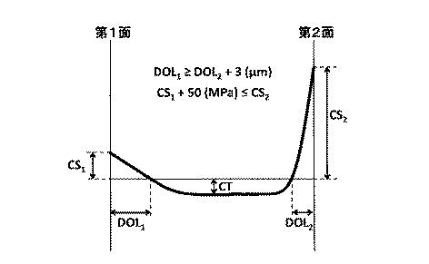
すなわち、本発明の化学強化ガラスは、第1面及び前記第1面に対向する第2面を有する化学強化ガラスであって、前記第1面の圧縮応力層深さDOL1(μm)が前記第2面の圧縮応力層深さDOL2(μm)よりも3μm以上大きく、前記第2面の表面圧縮応力CS2(MPa)が前記第1面の表面圧縮応力CS1(MPa)よりも50MPa以上大きいものである。 That is, the chemically strengthened glass of the present invention is a chemically strengthened glass having a first surface and a second surface facing the first surface, and the compressive stress layer depth DOL 1 (μm) of the first surface is the above-mentioned. The compressive stress layer depth DOL 2 (μm) of the second surface is 3 μm or more, and the surface compressive stress CS 2 (MPa) of the second surface is 50 MPa than the surface compressive stress CS 1 (MPa) of the first surface. It's bigger than that.
また、本発明の化学強化ガラスは、以下の関係式(1)
(CS1−CS2)×(DOL1−DOL2)<−1500 (1)
を満たすことが好ましい。
Further, the chemically strengthened glass of the present invention has the following relational expression (1):
(CS 1 -CS 2 ) × (DOL 1 -DOL 2 ) <− 1500 (1)
It is preferable to satisfy.
また、本発明の化学強化ガラスにおいては、前記第1面の圧縮応力層深さDOL1(μm)が15μm以上であることが好ましい。
また、本発明の化学強化ガラスにおいては、前記第1面の表面圧縮応力CS1(MPa)が100MPa以上であることが好ましい。
また、本発明の化学強化ガラスにおいては、前記第2面の圧縮応力層深さDOL2(μm)が5μm以上であることが好ましい。
また、本発明の化学強化ガラスにおいては、前記第2面の表面圧縮応力CS2(MPa)が500MPa以上であることが好ましい。
In the chemically strengthened glass of the present invention, it is preferable that the first surface of the compressive stress layer depth DOL 1 ([mu] m) is 15μm or more.
In the chemically strengthened glass of the present invention, it is preferable that the first side surface compressive stress CS 1 of (MPa) is not less than 100 MPa.
In the chemically strengthened glass of the present invention, it is preferable that the second surface of the compressive stress layer depth DOL 2 ([mu] m) is 5μm or more.
In the chemically strengthened glass of the present invention, it is preferable that the surface compressive stress CS 2 (MPa) of the second surface is 500 MPa or more.
また、本発明の化学強化ガラスの曲率半径は、15000mm以上であってもよい。あるいは、本発明の化学強化ガラスの曲率半径は、15000mm未満であってもよい。
また、本発明の化学強化ガラスは、曲面ガラス基板を化学強化したものであってもよい。
Further, the radius of curvature of the chemically strengthened glass of the present invention may be 15000 mm or more. Alternatively, the radius of curvature of the chemically strengthened glass of the present invention may be less than 15000 mm.
Moreover, the chemically strengthened glass of the present invention may be obtained by chemically strengthening a curved glass substrate.
また、本発明の化学強化ガラスは、以下の関係式(2)及び(3)
[Dh(E)−Dh(1)]<0 (2)
[Dh(E)−Dh(2)]>0 (3)
を満たすことが好ましい。
(ここで、Dh(E)は前記化学強化ガラスの端面をEPMAにより測定したときに、前記端面の最表面から深さ80μmまでの交換イオンX線強度の積分値をS(E)として、前記端面の最表面からの交換イオンX線強度の積分値がS(E)/2となる深さであり、
Dh(1)は前記化学強化ガラスの第1面をEPMAにより測定したときに、前記第1面の最表面から深さ80μmまでの交換イオンX線強度の積分値をS(1)として、前記第1面の最表面からの交換イオンX線強度の積分値がS(1)/2となる深さであり、
Dh(2)は前記化学強化ガラスの第2面をEPMAにより測定したときに、前記第2面の最表面から深さ80μmまでの交換イオンX線強度の積分値をS(2)として、前記第2面の最表面からの交換イオンX線強度の積分値がS(2)/2となる深さである。)
The chemically strengthened glass of the present invention has the following relational expressions (2) and (3):
[Dh (E) −Dh (1)] <0 (2)
[Dh (E) -Dh (2)]> 0 (3)
It is preferable to satisfy.
(Here, Dh (E) is the integral value of the exchange ion X-ray intensity from the outermost surface of the end face to a depth of 80 μm when the end face of the chemically strengthened glass is measured by EPMA, The depth at which the integrated value of the exchange ion X-ray intensity from the outermost surface of the end face is S (E) / 2,
When Dh (1) is measured by EPMA on the first surface of the chemically strengthened glass, the integrated value of the exchange ion X-ray intensity from the outermost surface of the first surface to a depth of 80 μm is defined as S (1), A depth at which the integral value of the exchange ion X-ray intensity from the outermost surface of the first surface is S (1) / 2,
When Dh (2) is measured by EPMA on the second surface of the chemically strengthened glass, the integrated value of the exchange ion X-ray intensity from the outermost surface of the second surface to a depth of 80 μm is set as S (2), The depth at which the integrated value of the exchange ion X-ray intensity from the outermost surface of the second surface is S (2) / 2. )
本発明の化学強化ガラスは、第1面の圧縮応力層深さDOL1が第2面の圧縮応力層深さDOL2よりも3μm以上大きく、第2面の表面圧縮応力CS2が第1面の表面圧縮応力CS1よりも50MPa以上大きいという、厚み方向に非対称な応力プロファイルを有する。したがって、化学強化ガラスに所望される化学強化特性がその面に応じて異なる用途に、好適に使用することができる。 In the chemically strengthened glass of the present invention, the compressive stress layer depth DOL 1 of the first surface is 3 μm or more larger than the compressive stress layer depth DOL 2 of the second surface, and the surface compressive stress CS 2 of the second surface is the first surface. from the surface compressive stress CS 1 of that least 50MPa large, having an asymmetric stress profile in the thickness direction. Therefore, the chemical strengthening characteristics desired for the chemically strengthened glass can be suitably used for applications that differ depending on the surface.
以下、本発明の実施形態について詳細に説明する。 Hereinafter, embodiments of the present invention will be described in detail.
本発明の化学強化ガラスは、第1面及び第1面に対向する第2面を有する化学強化ガラスであって、第1面の(圧縮)応力層深さDOL1が第2面の(圧縮)応力層深さDOL2よりも3μm以上大きく、第2面の表面圧縮応力CS2が第1面の表面圧縮応力CS1よりも50MPa以上大きいものである。 The chemically strengthened glass of the present invention is a chemically strengthened glass having a first surface and a second surface opposite to the first surface, and the (compressed) stress layer depth DOL 1 of the first surface is the second surface (compressed). ) 3 μm or more larger than the stress layer depth DOL 2 , and the surface compressive stress CS 2 of the second surface is 50 MPa or more larger than the surface compressive stress CS 1 of the first surface.
本発明の一実施形態に係る化学強化ガラスの応力プロファイルを図2に示す。図2に示されるように、本実施形態の化学強化ガラスは、第1面の応力層深さDOL1が第2面の応力層深さDOL2よりも3μm以上大きく、第2面の表面圧縮応力CS2が第1面の表面圧縮応力CS1よりも50MPa以上大きい、厚み方向に非対称な応力プロファイルを有する。 FIG. 2 shows a stress profile of the chemically strengthened glass according to one embodiment of the present invention. As shown in FIG. 2, the chemically strengthened glass of the present embodiment has a stress layer depth DOL 1 of the first surface that is 3 μm or more larger than the stress layer depth DOL 2 of the second surface, and the surface compression of the second surface. The stress CS 2 has a stress profile that is asymmetric in the thickness direction and is 50 MPa or more larger than the surface compressive stress CS 1 of the first surface.
第1面の応力層深さDOL1は、第2面の応力層深さDOL2よりも3μm以上大きければ特に限定されないが、15μm以上であると、傷耐性があるため好ましい。第1面の応力層深さDOL1は、より好ましくは20μm以上であり、さらに好ましくは40μm以上である。 The stress layer depth DOL 1 of the first surface is not particularly limited as long as it is 3 μm or more larger than the stress layer depth DOL 2 of the second surface, but is preferably 15 μm or more because it has scratch resistance. The stress layer depth DOL 1 of the first surface is more preferably 20 μm or more, and further preferably 40 μm or more.
第2面の応力層深さDOL2は、第1面の応力層深さDOL1よりも3μm以上小さければ特に限定されないが、高いCS2を実現する観点からは、好ましくは5μm以上である。 The stress layer depth DOL 2 of the second surface is not particularly limited as long as it is 3 μm or more smaller than the stress layer depth DOL 1 of the first surface, but is preferably 5 μm or more from the viewpoint of realizing high CS 2 .
第1面の応力層深さDOL1(μm)と第2面の応力層深さDOL2(μm)の差(DOL1−DOL2)は、第1面の応力層深さDOL1(単位:μm)の数値から、第2面の応力層深さDOL2(単位:μm)の数値を引いた数値を表すものとする。ここで、本実施形態においては、第1面の応力層深さDOL1は第2面の応力層深さDOL2よりも3μm以上大きいため、DOL1−DOL2は3(μm)以上となる。 The difference (DOL 1 −DOL 2 ) between the stress layer depth DOL 1 (μm) of the first surface and the stress layer depth DOL 2 (μm) of the second surface is the stress layer depth DOL 1 (unit) of the first surface. : Μm), and a value obtained by subtracting the value of the stress layer depth DOL 2 (unit: μm) of the second surface. Here, in this embodiment, since the stress layer depth DOL 1 of the first surface is 3 μm or more larger than the stress layer depth DOL 2 of the second surface, DOL 1 -DOL 2 is 3 (μm) or more. .
第1面の表面圧縮応力CS1は、第2面の表面圧縮応力CS2よりも50MPa以上小さければ特に限定されないが、傷耐性の観点からは、好ましくは100MPa以上であり、より好ましくは200MPa以上であり、さらに好ましくは300MPa以上である。 The surface compressive stress CS 1 of the first surface is not particularly limited as long as it is 50 MPa or more smaller than the surface compressive stress CS 2 of the second surface, but from the viewpoint of scratch resistance, it is preferably 100 MPa or more, more preferably 200 MPa or more. More preferably, it is 300 MPa or more.
第2面の表面圧縮応力CS2は、第1面の表面圧縮応力CS1よりも50MPa以上大きければ特に限定されないが、曲げ耐性の観点からは、好ましくは500MPa以上であり、より好ましくは600MPa以上であり、さらに好ましくは700MPa以上である。 Surface compressive stress CS 2 of the second surface is not particularly limited larger 50MPa or more than the surface compressive stress CS 1 of the first surface, from the viewpoint of bending resistance, preferably at least 500 MPa, more preferably at least 600MPa More preferably, it is 700 MPa or more.
第1面の表面圧縮応力CS1(MPa)と第2面の表面圧縮応力CS2(MPa)の差(CS1−CS2)は、第1面の表面圧縮応力CS1(単位:MPa)の数値から、第2面の表面圧縮応力CS2(単位:MPa)の数値を引いた数値を表すものとする。ここで、本実施形態においては、第2面の表面圧縮応力CS2は第1面の表面圧縮応力CS1よりも50MPa以上大きいため、CS1−CS2は−50(MPa)以下となる。 The difference (CS 1 −CS 2 ) between the surface compressive stress CS 1 (MPa) of the first surface and the surface compressive stress CS 2 (MPa) of the second surface is the surface compressive stress CS 1 (unit: MPa) of the first surface. The numerical value obtained by subtracting the numerical value of the surface compressive stress CS 2 (unit: MPa) of the second surface from the numerical value of In the present embodiment, since the surface compressive stress CS 2 of the second surface is larger 50MPa or more than the surface compressive stress CS 1 of the first surface, CS 1 -CS 2 becomes -50 (MPa) or less.
また、CS1−CS2とDOL1−DOL2とが、以下の関係式(1)を満たすことが好ましい。
(CS1−CS2)×(DOL1−DOL2)<−1500 (1)
Further, the CS 1 -CS 2 and DOL 1 -DOL 2 preferably satisfy the following relational expression (1).
(CS 1 -CS 2 ) × (DOL 1 -DOL 2 ) <− 1500 (1)
(CS1−CS2)×(DOL1−DOL2)が−1500より小さいと、化学強化ガラスに所望される化学強化特性が第1面と第2面に応じて異なる用途に好適に使用することができる化学強化特性をより良好に満たすことができ、ガラスの破砕をより効果的に防止することができる。なお、(CS1−CS2)×(DOL1−DOL2)は、−5000より小さいことがより好ましい。 When (CS 1 -CS 2 ) × (DOL 1 -DOL 2 ) is smaller than −1500, the chemical strengthening properties desired for the chemically strengthened glass are preferably used for different applications depending on the first surface and the second surface. The chemical strengthening properties that can be achieved can be better satisfied, and the glass can be more effectively prevented from being broken. Note that (CS 1 −CS 2 ) × (DOL 1 −DOL 2 ) is more preferably smaller than −5000.
また、上述したように、本実施形態の化学強化ガラスは、第1面の応力層深さDOL1が第2面の応力層深さDOL2よりも3μm以上大きく、第2面の表面圧縮応力CS2が第1面の表面圧縮応力CS1よりも50MPa以上大きい、厚み方向に非対称な応力プロファイルを有する。ここで、本実施形態の化学強化ガラスにおいても、ガラスの厚み方向の応力の積算値が0となるようにガラス内部に引張応力が生じるが、本実施形態によれば、厚み方向に対称な応力プロファイルを有する化学強化ガラス(両面の応力層深さDOLが本実施形態の化学強化ガラスの第1面の応力層深さDOL1と等しく、かつ、両面の表面圧縮応力CSが本実施形態の化学強化ガラスの第2面の表面圧縮応力CS2と等しい化学強化ガラス)に比較して、ガラス内部に生じる引張応力を小さくすることができる。したがって、本実施形態によれば、厚み方向に対称な応力プロファイルを有する化学強化ガラスと比較して、内部引張応力CTをより小さくすることができ、ガラスの破砕がより有効に抑制又は防止された化学強化ガラスとすることができる。 Further, as described above, the chemically strengthened glass of the present embodiment has a stress layer depth DOL 1 of the first surface that is 3 μm or more larger than the stress layer depth DOL 2 of the second surface, and the surface compressive stress of the second surface. CS 2 has a stress profile asymmetric in the thickness direction, which is 50 MPa or more larger than the surface compressive stress CS 1 of the first surface. Here, even in the chemically strengthened glass of this embodiment, tensile stress is generated inside the glass so that the integrated value of stress in the thickness direction of the glass becomes 0. According to this embodiment, stress symmetrical in the thickness direction is generated. Chemically tempered glass having a profile (the stress layer depth DOL on both sides is equal to the stress layer depth DOL 1 on the first side of the chemically tempered glass of this embodiment, and the surface compressive stress CS on both sides is the chemistry of this embodiment. compared to the second surface equal chemically tempered glass and the surface compressive stress CS 2) of the tempered glass, it is possible to reduce the tensile stress occurring in the glass. Therefore, according to the present embodiment, the internal tensile stress CT can be further reduced as compared with the chemically strengthened glass having a stress profile symmetric in the thickness direction, and the crushing of the glass is more effectively suppressed or prevented. It can be a chemically strengthened glass.
本実施形態の化学強化ガラスの内部引張応力CTは、特に限定されるものではないが、100MPa以下であると、ガラスの破砕を抑制又は防止する効果に優れるため好ましい。内部引張応力CTは、より好ましくは50MPa以下であり、さらに好ましくは30MPa以下である。 The internal tensile stress CT of the chemically strengthened glass of the present embodiment is not particularly limited, but is preferably 100 MPa or less because it is excellent in the effect of suppressing or preventing the glass from being crushed. The internal tensile stress CT is more preferably 50 MPa or less, and further preferably 30 MPa or less.
つづいて、本実施形態の化学強化ガラスの製造方法について説明する。 It continues and demonstrates the manufacturing method of the chemically strengthened glass of this embodiment.
本実施形態で使用されるガラス基板は、イオン交換可能なものであれば特に制限されず、例えば、ソーダライムガラス、アルミノシリケートガラス、ボロシリケートガラス、アルミノボロシリケートガラス等から適宜選択して使用することができる。 The glass substrate used in the present embodiment is not particularly limited as long as it is ion-exchangeable. For example, it is appropriately selected from soda lime glass, aluminosilicate glass, borosilicate glass, aluminoborosilicate glass, and the like. be able to.
本実施形態で使用されるガラス基板の組成の一例としては、モル%で表示した組成で、SiO2を50〜80%、Al2O3を0.1〜30%、Li2O+Na2O+K2Oを3〜30%、MgOを0〜25%、CaOを0〜25%およびZrO2を0〜5%含むガラスが挙げられるが、特に限定されない。より具体的には、以下のガラスの組成が挙げられる。なお、例えば、「MgOを0〜25%含む」とは、MgOは必須ではないが25%まで含んでもよい、の意である。
(i)モル%で表示した組成で、SiO2を63〜73%、Al2O3を0.1〜5.2%、Na2Oを10〜16%、K2Oを0〜1.5%、MgOを5〜13%及びCaOを4〜10%を含むガラス。
(ii)モル%で表示した組成で、SiO2を50〜74%、Al2O3を1〜10%、Na2Oを6〜14%、K2Oを3〜11%、MgOを2〜15%、CaOを0〜6%およびZrO2を0〜5%含有し、SiO2およびAl2O3の含有量の合計が75%以下、Na2OおよびK2Oの含有量の合計が12〜25%、MgOおよびCaOの含有量の合計が7〜15%であるガラス。
(iii)モル%で表示した組成で、SiO2を68〜80%、Al2O3を4〜10%、Na2Oを5〜15%、K2Oを0〜1%、MgOを4〜15%およびZrO2を0〜1%含有するガラス。
(iv)モル%で表示した組成で、SiO2を67〜75%、Al2O3を0〜4%、Na2Oを7〜15%、K2Oを1〜9%、MgOを6〜14%およびZrO2を0〜1.5%含有し、SiO2およびAl2O3の含有量の合計が71〜75%、Na2OおよびK2Oの含有量の合計が12〜20%であり、CaOを含有する場合その含有量が1%未満であるガラス。
(v)モル%で表示した組成で、SiO2を60〜72%、Al2O3を8〜16%、Na2Oを8〜18%、K2Oを0〜3%、MgOを0〜10%およびZrO2を0〜5%含有し、CaOを含有する場合その含有量が1%未満であるガラス。
As an example of the composition of the glass substrate used in the present embodiment, SiO 2 is 50 to 80%, Al 2 O 3 is 0.1 to 30%, Li 2 O + Na 2 O + K 2 with a composition expressed in mol%. Examples include glass containing 3 to 30% O, 0 to 25% MgO, 0 to 25% CaO, and 0 to 5% ZrO 2 , but are not particularly limited. More specifically, the following glass compositions may be mentioned. For example, “containing 0 to 25% of MgO” means that MgO is not essential but may contain up to 25%.
A composition which is displayed in (i) mole%, a SiO 2 63-73%, the Al 2 O 3 0.1~5.2%, 10~16 % of Na 2 O, 0 to 1 and K 2 O. Glass containing 5%, 5-13% MgO and 4-10% CaO.
(Ii) SiO 2 50-74%, Al 2 O 3 1-10%, Na 2 O 6-14%, K 2 O 3-11%,
(Iii) a composition which is displayed in mol%, the SiO 2 68~80%, Al 2 O 3 4-10%, 5-15% of Na 2 O, K 2 O 0 to 1%, 4 MgO 15% and glass containing ZrO 2 0 to 1%.
(Iv) a composition which is displayed in mole%, of SiO 2 67 to 75%, the Al 2 O 3 0 to 4%, a Na 2 O 7 to 15%, 1 to 9% of K 2 O, MgO 6 14 to 15% and ZrO 2 to 0 to 1.5%, the total content of SiO 2 and Al 2 O 3 is 71 to 75%, the total content of Na 2 O and K 2 O is 12 to 20 %, And when it contains CaO, its content is less than 1%.
(V) SiO 2 60-72%, Al 2 O 3 8-16%, Na 2 O 8-18%, K 2 O 0-3%, MgO 0 Glass which contains 10 to 10% and 0 to 5% of ZrO 2 and contains CaO when its content is less than 1%.
また、本実施形態の化学強化ガラスに使用されるガラス基板は、第1面および第2面の2つの主面と、これらに隣接して板厚を形成する端面とを有し、2つの主面は互いに平行な平坦面を形成していてもよい。ただし、ガラス基板の形態はこれに限定されず、例えば2つの主面は互いに平行でなくともよく、また、二つの主面の一方又は両方の全部又は一部が曲面であってもよい。より具体的には、ガラス基板は、例えば、反りの無い平板状のガラス基板であってもよく、また、湾曲した表面を有する曲面ガラス基板であってもよい。 Moreover, the glass substrate used for the chemically strengthened glass of the present embodiment has two main surfaces, a first surface and a second surface, and an end surface that forms a plate thickness adjacent to these two main surfaces. The surfaces may form flat surfaces parallel to each other. However, the form of the glass substrate is not limited to this. For example, the two principal surfaces may not be parallel to each other, and one or both of the two principal surfaces may be curved or partially curved. More specifically, the glass substrate may be, for example, a flat glass substrate without warpage or a curved glass substrate having a curved surface.
また、本実施形態で使用されるガラス基板の板厚は特に限定されない。 Moreover, the plate | board thickness of the glass substrate used by this embodiment is not specifically limited.
本実施形態の化学強化ガラスの製造方法においては、化学強化処理工程以外の工程は特に限定されることなく適宜選択すればよく、典型的には従来公知の工程を適用することができる。 In the method for producing chemically tempered glass of the present embodiment, steps other than the chemical tempering treatment step may be appropriately selected without particular limitation, and conventionally known steps can be typically applied.
例えば、ガラスの各成分の原料を調合し、ガラス溶融窯で加熱溶融する。その後、バブリング、撹拌、清澄剤の添加等によりガラスを均質化し、従来公知の成形法により所定の厚さのガラス基板に成形し、徐冷する。 For example, the raw material of each component of glass is prepared and heated and melted in a glass melting furnace. Thereafter, the glass is homogenized by bubbling, stirring, adding a clarifying agent, etc., formed into a glass substrate having a predetermined thickness by a conventionally known forming method, and slowly cooled.
ガラスの成形法としては、例えば、フロート法、プレス法、フュージョン法及びダウンドロー法が挙げられる。特に、大量生産に適したフロート法が好ましい。また、フロート法以外の連続成形法、すなわち、フュージョン法およびダウンドロー法も好ましい。 Examples of the glass forming method include a float method, a press method, a fusion method, and a downdraw method. In particular, a float method suitable for mass production is preferable. Further, continuous molding methods other than the float method, that is, the fusion method and the downdraw method are also preferable.
その後、成形したガラスを必要に応じて研削および研磨処理して、ガラス基板を形成する。そして、形成したガラス基板に後述する化学強化処理を施した後、洗浄および乾燥することにより、本実施形態の化学強化ガラスを製造することができる。 Thereafter, the molded glass is ground and polished as necessary to form a glass substrate. And after performing the chemical strengthening process mentioned later to the formed glass substrate, the chemically strengthened glass of this embodiment can be manufactured by wash | cleaning and drying.
以下に、本実施形態の化学強化ガラスの製造方法における化学強化処理について説明する。 Below, the chemical strengthening process in the manufacturing method of the chemically strengthened glass of this embodiment is demonstrated.
一般的に、化学強化処理におけるイオンの相互拡散現象は、以下に示す拡散方程式に従っている。なお、以下においては、イオン交換に供されるイオン半径のより大きなアルカリイオンがKイオンである場合について説明する。 In general, the interdiffusion phenomenon of ions in chemical strengthening treatment follows the diffusion equation shown below. In the following, a case where the alkali ion having a larger ion radius used for ion exchange is K ion will be described.
ここで、拡散係数Dは、Kイオンがガラス内部で拡がる速度の指標となる。物質移動係数Hは、Kイオンがガラス表層からガラス内部に侵入する速度の指標となる。また、拡散係数D及び物質移動係数Hは、いずれも温度に依存する。 Here, the diffusion coefficient D is an index of the speed at which K ions spread inside the glass. The mass transfer coefficient H is an index of the speed at which K ions enter the glass from the glass surface layer. Further, both the diffusion coefficient D and the mass transfer coefficient H depend on the temperature.
図3に、Kイオンを含む金属塩の融液(溶融塩)にガラス基板を浸漬させて化学強化処理を施した後、そのガラス基板を溶融塩から取り出して高温下に置いた場合の、応力プロファイルを示す。図3に示されるように、まず、溶融塩にガラス基板を浸漬させて化学強化処理を施すと、イオン交換とともにイオンの拡散が生じ、(a)に示される応力プロファイルとなる。その後、ガラス基板を溶融塩から取り出して高温下に置くと、溶融塩からのガラス表面へのKイオンの供給が無くなるため、イオン交換は生じないが、ガラスが高温下に置かれているため、ガラス内部でのイオンの拡散が進行する。その結果、応力がなまって表面圧縮応力CSが小さくなるとともに、圧縮応力層深さ(DOL)が大きくなって、(b)に実線で示される応力プロファイルへと変化する。 FIG. 3 shows the stress when a glass substrate is immersed in a melt (molten salt) of a metal salt containing K ions and subjected to chemical strengthening treatment, and then the glass substrate is taken out of the molten salt and placed at a high temperature. Indicates a profile. As shown in FIG. 3, when a glass substrate is first immersed in a molten salt and subjected to a chemical strengthening treatment, ion diffusion occurs along with ion exchange, resulting in a stress profile shown in (a). After that, when the glass substrate is taken out from the molten salt and placed at a high temperature, the supply of K ions from the molten salt to the glass surface is lost, so ion exchange does not occur, but the glass is placed at a high temperature, Ion diffusion proceeds inside the glass. As a result, the stress is reduced, the surface compressive stress CS is reduced, the compressive stress layer depth (DOL) is increased, and the stress profile changes to a solid line in (b).
本実施形態においては、上述した応力がなまる現象を利用して、第1面の応力層深さDOL1が第2面の応力層深さDOL2よりも3μm以上大きく、第2面の表面圧縮応力CS2が第1面の表面圧縮応力CS1よりも50MPa以上大きい、厚み方向に非対称な応力プロファイルを有する化学強化ガラスを作製する。本実施形態の化学強化ガラスの製造方法における化学強化処理の工程を、図4を用いて説明する。 In the present embodiment, the stress layer depth DOL 1 of the first surface is 3 μm or more larger than the stress layer depth DOL 2 of the second surface by utilizing the phenomenon that the stress is reduced as described above, and the surface of the second surface A chemically strengthened glass having an asymmetric stress profile in the thickness direction, in which the compressive stress CS 2 is 50 MPa or more larger than the surface compressive stress CS 1 of the first surface, is produced. The process of the chemical strengthening process in the manufacturing method of the chemically strengthened glass of this embodiment is demonstrated using FIG.
図4に示すように、まず、ガラス基板の片面(第1面)に化学強化処理を施す。これにより、第1面側でイオン交換及びイオンの拡散が進行し、(a)に示される応力プロファイルとなる。続いて、第1面に対する化学強化処理を停止した後、ガラス基板の他面(第2面)に化学強化処理を施す。これにより、第2面側ではイオン交換及びイオンの拡散が進行する。一方、第1面側では、化学強化処理に供されるイオンの供給が無いため、イオン交換は生じないため、応力がなまる。しかしながら、第1面側でも、第2面に対する化学強化処理における熱の影響によってイオンの拡散は進行する。その結果、応力プロファイルは、(b)に実線で示されるように変化する。 As shown in FIG. 4, first, a chemical strengthening process is performed on one side (first side) of the glass substrate. Thereby, ion exchange and ion diffusion proceed on the first surface side, and the stress profile shown in FIG. Subsequently, after the chemical strengthening process for the first surface is stopped, the other surface (second surface) of the glass substrate is subjected to the chemical strengthening process. Thereby, ion exchange and ion diffusion proceed on the second surface side. On the other hand, on the first surface side, since there is no supply of ions used for the chemical strengthening treatment, ion exchange does not occur, and therefore stress is reduced. However, also on the first surface side, diffusion of ions proceeds due to the influence of heat in the chemical strengthening process on the second surface. As a result, the stress profile changes as indicated by the solid line in (b).
その後、第2面に対する化学強化処理を停止することにより、(c)に示されるような、第1面の応力層深さDOL1が第2面の応力層深さDOL2よりも3μm以上大きく、第2面の表面圧縮応力CS2が第1面の表面圧縮応力CS1よりも50MPa以上大きい、厚み方向に非対称な応力プロファイルを有する化学強化ガラスを得ることができる(なお、この点について、(c)では、第1面については「高DOL」と、また、第2面については「高CS」と、それぞれ省略して示している)。 Then, by stopping the chemical strengthening process for the second surface, the stress layer depth DOL 1 of the first surface is 3 μm or more larger than the stress layer depth DOL 2 of the second surface as shown in (c). the surface compressive stress CS 2 of the second surface is greater than 50MPa than the surface compressive stress CS 1 of the first surface, can be obtained chemically reinforced glass having an asymmetric stress profile in the thickness direction (this point, In (c), “high DOL” is omitted for the first surface, and “high CS” is omitted for the second surface).
ここで、ガラス基板の片面に化学強化処理を施す方法としては、たとえば、化学強化処理を施す面に無機塩を塗布した後、これを熱処理する方法が挙げられる。 Here, as a method of performing the chemical strengthening treatment on one surface of the glass substrate, for example, a method of applying an inorganic salt to the surface subjected to the chemical strengthening treatment and then heat-treating the inorganic salt can be mentioned.
この方法に使用される無機塩は、たとえば、ガラス表面のイオン半径が小さなアルカリ金属イオン(典型的には、LiイオンまたはNaイオン)をイオン半径のより大きなアルカリイオン(典型的には、Kイオン)に交換し、ガラス表面に圧縮応力層を形成する役割を有する。ただし、ガラス表面のイオン半径が大きなイオンが、イオン半径の小さなイオンで交換されてもよい。 The inorganic salt used in this method is, for example, an alkali metal ion (typically Li ion or Na ion) having a small ionic radius on the glass surface and an alkali ion (typically K ion) having a larger ionic radius. ) To form a compressive stress layer on the glass surface. However, ions having a large ion radius on the glass surface may be exchanged with ions having a small ion radius.
無機塩の組成は、とくに制限されないが、例えば、カリウム化合物を含有する。カリウム化合物としては、例えば、KNO3、KCl、KBr、KI、KFおよびK2SO4等が挙げられる。また、カリウム化合物以外に、例えば、NaNO3等のナトリウム化合物を5%程度以下含有するものも使用可能である。 The composition of the inorganic salt is not particularly limited, but contains, for example, a potassium compound. Examples of the potassium compound include KNO 3 , KCl, KBr, KI, KF, K 2 SO 4 and the like. In addition to the potassium compound, for example, it can also be used those containing sodium compounds such as NaNO 3 below about 5%.
なお、無機塩には、溶媒および増粘剤等の添加物を添加してもよい。溶媒としては、例えば、カリウム化合物を溶解、分散若しくは懸濁させることが可能な液体または液体が基となる物質が挙げられ、水またはアルコールが基となるものでもよい。増粘剤としては、例えば、有機樹脂および有機溶剤等が挙げられる。 In addition, you may add additives, such as a solvent and a thickener, to inorganic salt. Examples of the solvent include a liquid capable of dissolving, dispersing, or suspending a potassium compound, or a substance based on the liquid, and may be based on water or alcohol. Examples of the thickener include organic resins and organic solvents.
有機樹脂としては、熱処理温度において分解する樹脂を用いればよく、水洗により容易に除去できるものが好ましい。例えば、このような特性を有する、セルロース樹脂、メチルセルロース樹脂、セルロースアセテート樹脂、セルロースニトレート樹脂、セルロースアセテートプチレート樹脂、アクリル樹脂および石油樹脂等が挙げられる。 As the organic resin, a resin that decomposes at a heat treatment temperature may be used, and those that can be easily removed by washing with water are preferable. Examples thereof include cellulose resin, methyl cellulose resin, cellulose acetate resin, cellulose nitrate resin, cellulose acetate petrate resin, acrylic resin, and petroleum resin having such characteristics.
有機溶剤は、金属化合物及び有機樹脂を容易に分散可能で乾燥時に容易に揮発するものであることが好ましく、具体的には、室温(20℃)では液体であり、50〜200℃程度で揮発する有機溶剤であることが好ましい。このような有機溶剤としては、例えば、メタノールおよびエタノール等のアルコール類並びにジメチルエーテルおよびアセトン等のケトン類などが挙げられる。 The organic solvent is preferably one that can disperse the metal compound and the organic resin easily and volatilizes easily when dried. Specifically, the organic solvent is liquid at room temperature (20 ° C.) and volatilizes at about 50 to 200 ° C. It is preferable that it is an organic solvent. Examples of such an organic solvent include alcohols such as methanol and ethanol, and ketones such as dimethyl ether and acetone.
本発明で使用される無機塩に対する添加物の添加量については、特に限定されない。 The addition amount of the additive to the inorganic salt used in the present invention is not particularly limited.
また、本発明で使用される無機塩は、塗布し易いという観点から、各プロセスに応じて粘度を調整可能であることが好ましい。粘度を調整する方法としては、例えば、カオリンのようなクレー、水またはアルミノシリケートファイバーのような流動性調整剤を添加する方法が挙げられる。 Moreover, it is preferable that the viscosity of the inorganic salt used in the present invention can be adjusted according to each process from the viewpoint of easy application. Examples of the method for adjusting the viscosity include a method of adding a fluidity adjusting agent such as clay such as kaolin, water, or aluminosilicate fiber.
本発明で使用される無機塩の粘度は適宜調整可能であるが、20℃における粘度が、通常200〜100000mPaであることが好ましい。無機塩の粘度は、例えば粘度計(株式会社マルコム社製PM−2B)、粘度カップ(アネスト岩田株式会社製NK−2)等により測定可能である。 The viscosity of the inorganic salt used in the present invention can be adjusted as appropriate, but the viscosity at 20 ° C. is usually preferably 200 to 100,000 mPa. The viscosity of the inorganic salt can be measured by, for example, a viscometer (PM-2B manufactured by Malcolm Co., Ltd.), a viscosity cup (NK-2 manufactured by Anest Iwata Co., Ltd.), or the like.
ガラス基板の表面および裏面に無機塩を塗布する方法としては、公知のコーターを用いればよく、特に制限されないが、例えば、カーテンコーター、バーコーター、ロールコーター、ダイコーターおよびスプレーコート等が挙げられる。 A method for applying the inorganic salt to the front and back surfaces of the glass substrate may be a known coater, and is not particularly limited. Examples thereof include curtain coaters, bar coaters, roll coaters, die coaters, and spray coaters.
また、熱処理温度は、無機塩の種類により適宜設定すればよいが、通常350〜600℃であることが好ましく、より好ましくは400〜550℃である。 Moreover, what is necessary is just to set the heat processing temperature suitably with the kind of inorganic salt, but it is preferable that it is 350-600 degreeC normally, More preferably, it is 400-550 degreeC.
熱処理時間は、適宜設定可能であるが、所定の熱処理温度に到達してから、通常5分〜10時間であることが好ましく、より好ましくは30分〜4時間である。 The heat treatment time can be appropriately set, but it is usually preferably 5 minutes to 10 hours, more preferably 30 minutes to 4 hours after reaching a predetermined heat treatment temperature.
また、化学強化処理を停止させるには、例えば、熱処理後の化学強化ガラスを洗浄し、表面の無機塩を除去する等すればよい。 In order to stop the chemical strengthening treatment, for example, the chemically strengthened glass after the heat treatment may be washed to remove inorganic salts on the surface.
なお、ガラス基板の第1面におけるイオン交換量がガラス基板の第2面におけるイオン交換量と異なると、第1面と第2面の間で膨張差が生じ、得られる化学強化ガラスに反りが生じる場合がある。したがって、化学強化処理による反りの発生を防止するためには、ガラス基板の第1面におけるイオン交換量とガラス基板の第2面におけるイオン交換量を等しくすることが好ましい。たとえば、主面である第1面と第2面が互いに平行な平坦面であるガラス基板を用いて、当該ガラス基板の第1面に所定の条件(熱処理温度、熱処理時間、無機塩の組成等)で化学強化処理を施した後、第2面にも同条件で化学強化処理を施すことにより、反りが無く、かつ非対称な応力プロファイルを有する化学強化ガラスを得ることができる。その際、第1面に化学強化処理を施した時の表面圧縮応力(CS)と第2面に化学強化処理を施した時の表面圧縮応力(CS)との差の絶対値(以下、CS差の絶対値ともいう)が20MPa以下、かつ、第1面に化学強化処理を施した時の圧縮応力層深さ(DOL)と第2面に化学強化処理を施した時の圧縮応力層深さ(DOL)との差の絶対値(以下、DOL差の絶対値ともいう)が2μm以下となるような化学強化処理条件を選択することが好ましい。また、前記CS差の絶対値が10MPa以下、かつ、前記DOL差の絶対値が1μm以下となる化学処理条件がより好ましく、前記CS差の絶対値が0MPa、かつ、前記DOL差の絶対値が0μmとなる化学処理条件が特に好ましい。ただし、化学強化処理による反りの発生が許容される場合には、ガラス基板の第1面に対する化学強化処理条件とガラス基板の第2面に対する化学強化処理条件を異なる条件に設定してもよい。 In addition, if the ion exchange amount on the first surface of the glass substrate is different from the ion exchange amount on the second surface of the glass substrate, a difference in expansion occurs between the first surface and the second surface, and the resulting chemically strengthened glass is warped. May occur. Therefore, in order to prevent the occurrence of warpage due to the chemical strengthening treatment, it is preferable to make the ion exchange amount on the first surface of the glass substrate equal to the ion exchange amount on the second surface of the glass substrate. For example, using a glass substrate in which the first surface and the second surface, which are the main surfaces, are flat surfaces parallel to each other, predetermined conditions (heat treatment temperature, heat treatment time, inorganic salt composition, etc.) are applied to the first surface of the glass substrate. ), The second surface is subjected to the chemical strengthening treatment under the same conditions, whereby a chemically strengthened glass having no warpage and an asymmetric stress profile can be obtained. At that time, the absolute value of the difference between the surface compressive stress (CS) when the first surface is chemically strengthened and the surface compressive stress (CS) when the second surface is chemically strengthened (hereinafter referred to as CS). The absolute value of the difference) is 20 MPa or less, and the compressive stress layer depth (DOL) when the first surface is chemically strengthened and the compressive stress layer depth when the second surface is chemically strengthened It is preferable to select a chemical strengthening treatment condition such that the absolute value of the difference from the thickness (DOL) (hereinafter also referred to as the absolute value of the DOL difference) is 2 μm or less. More preferably, the chemical treatment conditions are such that the absolute value of the CS difference is 10 MPa or less and the absolute value of the DOL difference is 1 μm or less, the absolute value of the CS difference is 0 MPa, and the absolute value of the DOL difference is A chemical treatment condition of 0 μm is particularly preferred. However, when the occurrence of warpage due to the chemical strengthening treatment is allowed, the chemical strengthening treatment conditions for the first surface of the glass substrate and the chemical strengthening treatment conditions for the second surface of the glass substrate may be set to different conditions.
また、厚み方向に非対称な応力プロファイルを有する化学強化ガラスを作製する方法としては、上述した方法以外にも、例えば、イオン交換を阻害する膜(以下、イオン交換阻害膜ともいう)を使用する方法が挙げられる。当該方法においては、例えば、第2面にイオン交換阻害膜を設けた状態でガラス基板を溶融塩に浸漬してイオン交換処理を行った後、溶融塩からガラス基板を引き上げる。その後、第2面に設けたイオン交換阻害膜を取り除き、第1面にイオン交換阻害膜を設けた状態でガラス基板を溶融塩に浸漬してイオン交換処理を行う。このようにすることで、厚み方向に非対称な応力プロファイルを有する化学強化ガラス基板を作製することができる。また、前記溶融塩としては、例えば、硝酸カリウム塩、硫酸カリウム塩、及び塩化カリウム塩等のアルカリ硝酸塩、アルカリ硫酸塩及びアルカリ塩化物塩などが挙げられる。これらの溶融塩は単独で用いてもよいし、複数種を組み合わせて用いてもよい。また、化学強化特性を調整するために、ナトリウムを含む塩を混ぜてもよい。また、イオン交換処理の処理条件は、特に限定されず、ガラスの特性及び溶融塩等を考慮して最適な条件を選択すればよい。 Moreover, as a method for producing a chemically strengthened glass having an asymmetric stress profile in the thickness direction, for example, a method using a film that inhibits ion exchange (hereinafter also referred to as an ion exchange inhibiting film) other than the above-described method. Is mentioned. In this method, for example, after a glass substrate is immersed in a molten salt in a state where an ion exchange inhibiting film is provided on the second surface and subjected to an ion exchange treatment, the glass substrate is pulled up from the molten salt. Thereafter, the ion exchange inhibition film provided on the second surface is removed, and the ion exchange treatment is performed by immersing the glass substrate in the molten salt with the ion exchange inhibition film provided on the first surface. By doing in this way, the chemically strengthened glass substrate which has an asymmetrical stress profile in the thickness direction can be produced. Examples of the molten salt include alkali nitrates such as potassium nitrate, potassium sulfate, and potassium chloride, alkali sulfates, and alkali chlorides. These molten salts may be used alone or in combination of two or more. Further, a salt containing sodium may be mixed in order to adjust the chemical strengthening characteristics. Moreover, the process conditions of an ion exchange process are not specifically limited, What is necessary is just to select optimal conditions in consideration of the characteristic of glass, molten salt, etc.
また、上記イオン交換阻害膜を使用する方法の他にも、例えば、化学強化処理を施す面に無機塩を塗布し電圧を印加することで、イオンを注入する方法も適用可能である。当該方法においては、電圧や無機塩の濃度等の各種条件を変えながら片面ずつイオン注入を行うことで、厚み方向に非対称な応力プロファイルを有する化学強化ガラスを作製することができる。 In addition to the method using the ion exchange inhibition membrane, for example, a method of implanting ions by applying an inorganic salt to the surface to be chemically strengthened and applying a voltage is also applicable. In this method, chemically tempered glass having an asymmetric stress profile in the thickness direction can be produced by performing ion implantation on each side while changing various conditions such as voltage and inorganic salt concentration.
本発明の一実施形態においては、化学強化ガラスの曲率半径が15000mm以上であってもよい。ここで、「化学強化ガラスの曲率半径が15000mm以上である」とは、化学強化ガラスの第1面を凸面、第2面を凹面とし、あるいは、第1面を凹面、第2面を凸面として、僅かに観測される湾曲の曲率半径が15000mm以上であることを表す。このような化学強化ガラスは、例えば、平板状のガラス基板に、第1面におけるイオン交換量と第2面におけるイオン交換量の絶対差が小さくなる条件で前述のような化学強化処理(イオン交換処理)を施すことにより得られ、当該イオン交換量の絶対差に起因する反りが小さいものである。 In one embodiment of the present invention, the radius of curvature of the chemically strengthened glass may be 15000 mm or more. Here, “the radius of curvature of chemically strengthened glass is 15000 mm or more” means that the first surface of chemically strengthened glass is convex and the second surface is concave, or the first surface is concave and the second surface is convex. The curvature radius of the slightly observed curvature is 15000 mm or more. Such a chemically strengthened glass is, for example, applied to a flat glass substrate under the condition that the absolute difference between the ion exchange amount on the first surface and the ion exchange amount on the second surface is small (ion exchange) as described above. The warpage caused by the absolute difference in the ion exchange amount is small.
また、本発明の一実施形態においては、化学強化ガラスの曲率半径が15000mm未満であってもよい。ここで、「化学強化ガラスの曲率半径が15000mm未満である」とは、化学強化ガラスの第1面を凸面、第2面を凹面とし、あるいは、第1面を凹面、第2面を凸面として、観測される湾曲の曲率半径が15000mm未満であることを表す。このような化学強化ガラスは、例えば、平板状のガラス基板に、第1面におけるイオン交換量と第2面におけるイオン交換量の絶対差が大きくなる条件で前述のような化学強化処理(イオン交換処理)を施すことにより得られ、当該イオン交換量の絶対差に起因する反りが大きいものである。 Moreover, in one Embodiment of this invention, the curvature radius of chemically strengthened glass may be less than 15000 mm. Here, “the radius of curvature of chemically strengthened glass is less than 15000 mm” means that the first surface of chemically strengthened glass is convex and the second surface is concave, or the first surface is concave and the second surface is convex. The curvature radius of the observed curvature is less than 15000 mm. Such chemically tempered glass is, for example, applied to a flat glass substrate under the condition that the absolute difference between the ion exchange amount on the first surface and the ion exchange amount on the second surface becomes large (ion exchange as described above). The warpage resulting from the absolute difference in the ion exchange amount is large.
また、本発明の一実施形態に係る化学強化ガラスは、曲面ガラス基板に前述した化学強化処理を施すことにより得られるものであってもよい。 Moreover, the chemically strengthened glass which concerns on one Embodiment of this invention may be obtained by performing the chemical strengthening process mentioned above to the curved glass substrate.
また、本発明の化学強化ガラスにおいては、端面の最表面から深さ80μmまでのEPMAにより測定される交換イオンX線強度の積分値(S(E))が、第1面の最表面から深さ80μmまでのEPMAにより測定される交換イオンX線強度の積分値(S(1))及び第2面の最表面から深さ80μmまでのEPMAにより測定される交換イオンX線強度の積分値(S(2))よりも大きいことが好ましい。すなわち、S(E)>S(1)かつS(E)>S(2)であることが好ましい。この関係を満たす化学強化ガラスは、第1面及び第2面に加えて、端面も充分に化学強化された化学強化ガラスである。
このような化学強化ガラスは、第1面に化学強化処理を施す際に端面にも化学強化処理が施され、かつ、第2面に化学強化処理を施す際に端面にも化学強化処理が施されるように、ガラスの板厚や各化学強化処理条件を適宜調整することにより得ることができる。
In the chemically tempered glass of the present invention, the integrated value (S (E)) of the exchange ion X-ray intensity measured by EPMA from the outermost surface of the end surface to a depth of 80 μm is deep from the outermost surface of the first surface. Integral value of exchange ion X-ray intensity (S (1)) measured by EPMA up to 80 μm in depth and integral value of exchange ion X-ray intensity measured by EPMA from the outermost surface of the second surface to a depth of 80 μm (S It is preferable that it is larger than S (2)). That is, it is preferable that S (E)> S (1) and S (E)> S (2). The chemically tempered glass satisfying this relationship is a chemically tempered glass in which the end surface is sufficiently chemically strengthened in addition to the first surface and the second surface.
Such a chemically strengthened glass is subjected to a chemical strengthening treatment on the end surface when the first surface is subjected to the chemical strengthening treatment, and is also subjected to the chemical strengthening treatment on the end surface when the second surface is subjected to the chemical strengthening treatment. As described above, it can be obtained by appropriately adjusting the plate thickness of the glass and each chemical strengthening treatment condition.
なお、本明細書中において、「交換イオン」とは、化学強化処理としてのイオン交換処理によって、ガラス中の被交換イオンと交換され、ガラス中に侵入するイオンを表す。また、「被交換イオン」とは、イオン交換処理によって、交換イオンと交換され、ガラスの外部に出ていくイオンを表す。イオン交換処理により、ガラス中の交換イオンの濃度は増加し、一方、ガラス中の被交換イオンの濃度は減少することとなる。 In the present specification, “exchange ions” refers to ions that are exchanged with exchanged ions in the glass by an ion exchange treatment as a chemical strengthening treatment and enter the glass. Further, “exchanged ions” refers to ions that are exchanged with exchange ions by ion exchange treatment and exit to the outside of the glass. By the ion exchange treatment, the concentration of exchange ions in the glass increases, while the concentration of ions to be exchanged in the glass decreases.
なお、化学強化ガラスの第1面、第2面及び端面のそれぞれにおける深さ方向の交換イオンX線強度は、EPMA(Electron Probe Micro Analyzer、電子線マイクロアナライザー)により測定することができる。 In addition, the exchange ion X-ray intensity | strength of the depth direction in each of the 1st surface of a chemically strengthened glass, a 2nd surface, and an end surface can be measured by EPMA (Electron Probe MicroAnalyzer, electron beam microanalyzer).
また、本発明の化学強化ガラスは、以下の関係式(2)及び(3)を満たすことが好ましい。
[Dh(E)−Dh(1)]<0 (2)
[Dh(E)−Dh(2)]>0 (3)
上記関係式(2)及び(3)の関係を満たす本発明の化学強化ガラスは、第1面及び第2面に加えて、端面も充分に化学強化された化学強化ガラスである。
Moreover, it is preferable that the chemically strengthened glass of the present invention satisfies the following relational expressions (2) and (3).
[Dh (E) −Dh (1)] <0 (2)
[Dh (E) -Dh (2)]> 0 (3)
The chemically tempered glass of the present invention satisfying the relations of the above relational expressions (2) and (3) is a chemically tempered glass in which the end face is sufficiently chemically strengthened in addition to the first and second faces.
ここで、Dh(E)は前記化学強化ガラスの端面をEPMAにより測定したときに、前記端面の最表面(深さ:0μm)から深さ80μmまでの交換イオンX線強度の積分値をS(E)として、前記端面の最表面からの交換イオンX線強度の積分値がS(E)/2となる深さである。
Dh(1)は前記化学強化ガラスの第1面をEPMAにより測定したときに、前記第1面の最表面(深さ:0μm)から深さ80μmまでの交換イオンX線強度の積分値をS(1)として、前記第1面の最表面からの交換イオンX線強度の積分値がS(1)/2となる深さである。
Dh(2)は前記化学強化ガラスの第2面をEPMAにより測定したときに、前記第2面の最表面(深さ:0μm)から深さ80μmまでの交換イオンX線強度の積分値をS(2)として、前記第2面の最表面からの交換イオンX線強度の積分値がS(2)/2となる深さである。
Dh(E)、Dh(1)及びDh(2)は、化学強化ガラスの端面、第1面及び第2面のそれぞれにおける深さ方向の交換イオンX線強度をEPMAにより測定した結果から、それぞれ算出することができる。
Here, Dh (E) is the integrated value of the exchange ion X-ray intensity from the outermost surface (depth: 0 μm) to the depth of 80 μm when the end surface of the chemically strengthened glass is measured by EPMA. E) is a depth at which the integrated value of the exchange ion X-ray intensity from the outermost surface of the end face is S (E) / 2.
Dh (1) is the integrated value of the exchange ion X-ray intensity from the outermost surface (depth: 0 μm) to the depth of 80 μm when the first surface of the chemically strengthened glass is measured by EPMA. (1) is the depth at which the integrated value of the exchange ion X-ray intensity from the outermost surface of the first surface is S (1) / 2.
Dh (2) is the integrated value of the exchange ion X-ray intensity from the outermost surface (depth: 0 μm) to the depth of 80 μm when the second surface of the chemically strengthened glass is measured by EPMA. (2) is the depth at which the integrated value of the exchange ion X-ray intensity from the outermost surface of the second surface is S (2) / 2.
Dh (E), Dh (1), and Dh (2) are obtained from the results of measuring the exchange ion X-ray intensity in the depth direction of each of the end face, first face, and second face of chemically strengthened glass by EPMA, respectively. Can be calculated.
上記関係式(2)及び(3)の関係を満たす本発明の化学強化ガラスは、以下の関係式(4)を満たすこととなる。
[Dh(E)−Dh(1)]×[Dh(E)−Dh(2)]<0 (4)
The chemically strengthened glass of the present invention that satisfies the relations (2) and (3) satisfies the following relational expression (4).
[Dh (E) −Dh (1)] × [Dh (E) −Dh (2)] <0 (4)
以上説明したように、本発明の化学強化ガラスは、第1面の圧縮応力層深さDOL1が第2面の圧縮応力層深さDOL2よりも3μm以上大きく、第2面の表面圧縮応力CS2が第1面の表面圧縮応力CS1よりも50MPa以上大きいという、厚み方向に非対称な応力プロファイルを有するものである。したがって、本発明の化学強化ガラスは、厚み方向に対称な応力プロファイルを有する化学強化ガラス(両面の圧縮応力層深さDOLが本発明の化学強化ガラスの第1面の圧縮応力層深さDOL1と等しく、かつ、両面の表面圧縮応力CSが本発明の化学強化ガラスの第2面の表面圧縮応力CS2と等しい化学強化ガラス)に比較して、ガラス内部に生じる引張応力を小さくすることができる。したがって、本発明によれば、厚み方向に対称な応力プロファイルを有する化学強化ガラスと比較して、内部引張応力CTをより小さくすることができるため、ガラスの破砕をより有効に抑制又は防止することができる。 As described above, in the chemically strengthened glass of the present invention, the compressive stress layer depth DOL 1 on the first surface is 3 μm or more larger than the compressive stress layer depth DOL 2 on the second surface, and the surface compressive stress on the second surface. CS 2 has a stress profile that is asymmetric in the thickness direction, ie, 50 MPa or more larger than the surface compressive stress CS 1 of the first surface. Therefore, chemically tempered glass of the present invention, the compressive stress layer depth of the first surface of the chemically tempered glass chemically tempered glass (compressive stress layer depth DOL of both sides present invention having a symmetric stress profile in the thickness direction DOL 1 The tensile stress generated in the glass can be reduced compared to the chemically tempered glass having the same surface compressive stress CS on both sides as the second surface compressive stress CS 2 of the chemically tempered glass of the present invention. it can. Therefore, according to the present invention, the internal tensile stress CT can be further reduced as compared with the chemically strengthened glass having a stress profile symmetrical in the thickness direction, so that the glass breakage can be more effectively suppressed or prevented. Can do.
本発明の化学強化ガラスは、例えば、携帯電話やスマートフォン等のモバイル機器、テレビ、パーソナルコンピュータ、タッチパネル等のディスプレイ装置のカバーガラス等として、有用に用いることができる。すなわち、ディスプレイ装置のカバーガラスには、露出している側の面(露出面)に種々の衝突物が衝突し、ガラスの損傷が生じる可能性がある。ここで、例えば、球状の衝突物等、衝突部分の角度が比較的大きい衝突物がカバーガラスの露出面に衝突すると、カバーガラスに曲げが生じ、カバーガラスの衝突面とは反対側の面(裏面)には、この曲げによる外力(引張応力)がかかる。したがって、この曲げによる外力に抗するように、カバーガラスの裏面の表面圧縮応力(CS)は、より大きいことが望ましい。また、鋭利な先端を有する衝突物等、衝突部分の角度が比較的小さい衝突物がカバーガラスの露出面に衝突することにより、カバーガラスの露出面に傷が入る場合があるが、その傷が圧縮応力層よりも深くに到達し、かつ、内部の引張応力が大きいと、カバーガラスの割れが生じてしまう。したがって、傷に強いカバーガラスとするためには、カバーガラスの露出面の圧縮応力層深さ(DOL)がより大きく、かつ、内部引張応力(CT)がより小さいことが望ましい。 The chemically tempered glass of the present invention can be usefully used as a cover glass of a display device such as a mobile device such as a mobile phone or a smartphone, a television, a personal computer, or a touch panel. That is, various collision objects may collide with the exposed surface (exposed surface) of the cover glass of the display device, and the glass may be damaged. Here, for example, when a collision object having a relatively large angle of the collision portion such as a spherical collision object collides with the exposed surface of the cover glass, the cover glass is bent, and the surface opposite to the collision surface of the cover glass ( External force (tensile stress) due to this bending is applied to the back surface. Therefore, it is desirable that the surface compressive stress (CS) on the back surface of the cover glass is larger so as to resist the external force due to this bending. In addition, a collision object with a relatively small angle of the collision part such as a collision object having a sharp tip may collide with the exposed surface of the cover glass, and the exposed surface of the cover glass may be scratched. If it reaches deeper than the compressive stress layer and the internal tensile stress is large, the cover glass will crack. Therefore, in order to obtain a cover glass that is resistant to scratches, it is desirable that the compressed stress layer depth (DOL) of the exposed surface of the cover glass is larger and the internal tensile stress (CT) is smaller.
ここで、本発明の化学強化ガラスは、第1面の圧縮応力層深さDOL1が第2面の圧縮応力層深さDOL2よりも3μm以上大きく、第2面の表面圧縮応力CS2が第1面の表面圧縮応力CS1よりも50MPa以上大きいので、例えば、圧縮応力層深さの大きい第1面を露出面とし、表面圧縮応力の大きい第2面を裏面とすることにより、ディスプレイ装置のカバーガラスとして望まれる特性を満足することができる。加えて、内部引張応力CTをより小さくすることができるため、ガラスの破砕をより有効に抑制又は防止することもできる。したがって、ディスプレイ装置のカバーガラスとして好適に使用することができる。 Here, in the chemically strengthened glass of the present invention, the compressive stress layer depth DOL 1 of the first surface is 3 μm or more larger than the compressive stress layer depth DOL 2 of the second surface, and the surface compressive stress CS 2 of the second surface is larger. since the first surface 50MPa or greater than the surface compressive stress CS 1, for example, the first surface having a large compressive stress layer depth and the exposed surface, by a second face having a large surface compressive stress and the rear surface, a display device The characteristics desired as a cover glass can be satisfied. In addition, since the internal tensile stress CT can be further reduced, it is possible to more effectively suppress or prevent the glass from being crushed. Therefore, it can be suitably used as a cover glass for a display device.
また、本発明の化学強化ガラスは、ディスプレイ装置のカバーガラス以外にも、面ごとに異なる化学強化特性が所望される種々の用途に有用に用いることができる。例えば、家屋やビル等の建築物の窓ガラス等の建築用資材、自動車等の車両に用いられる車両用部材(例えば、フロントガラス、ミラー、窓ガラス、内装部材など)、光学レンズ、医療機器、食器類等にも、有用に用いることができる。 Moreover, the chemically strengthened glass of the present invention can be usefully used for various applications in which different chemical strengthening characteristics are desired for each surface other than the cover glass of the display device. For example, building materials such as window glass for buildings such as houses and buildings, vehicle members used in vehicles such as automobiles (for example, windshields, mirrors, window glasses, interior members, etc.), optical lenses, medical equipment, It can be usefully used for tableware and the like.
以下、本発明を実施例によって説明するが、本発明はこれらにより限定されるものではない。 EXAMPLES Hereinafter, although an Example demonstrates this invention, this invention is not limited by these.
(実施例1)
まず、以下に示す組成のガラスを板厚が0.85mmとなるようにフロート法で製造し、50mm×50mmに切断し、ガラス基板を作製した。なお、作製したガラス基板は反りを有していなかった。
ガラス組成(モル%表示):SiO2 64.4%、Al2O3 8.0%、Na2O 12.5%、K2O 4.0%、MgO 10.5%、CaO 0.1%、SrO 0.1%、BaO 0.1%、ZrO2 0.5%
Example 1
First, a glass having the composition shown below was manufactured by a float process so that the plate thickness was 0.85 mm, and cut into 50 mm × 50 mm to prepare a glass substrate. In addition, the produced glass substrate did not have curvature.
Glass composition (in mol%): SiO 2 64.4%, Al 2 O 3 8.0%, Na 2 O 12.5%, K 2 O 4.0%, MgO 10.5%, CaO 0.1 %, SrO 0.1%, BaO 0.1%, ZrO 2 0.5%
続いて、作製したガラス基板の片面(第1面)に、下記の組成のペースト状の無機塩を、厚みが1.5mmとなるようにコーターを用いて塗布した。
ペースト状の無機塩の組成(質量比) 水:K2SO4:KNO3=6:5:1
Then, the paste-form inorganic salt of the following composition was apply | coated to the single side | surface (1st surface) of the produced glass substrate using the coater so that thickness might be set to 1.5 mm.
Composition (mass ratio) of paste-like inorganic salt Water: K 2 SO 4 : KNO 3 = 6: 5: 1
第1面にペースト状の無機塩を塗布したガラス基板を、加熱炉内に移し、500℃にて15分熱処理を行うことにより化学強化処理を行った。その後、ガラス基板を室温まで冷却し、純水で洗浄して第1面に塗布された無機塩を除去し、乾燥させた。 The glass substrate having the first surface coated with a paste-like inorganic salt was transferred into a heating furnace and subjected to a heat treatment at 500 ° C. for 15 minutes to perform a chemical strengthening treatment. Thereafter, the glass substrate was cooled to room temperature, washed with pure water to remove the inorganic salt applied to the first surface, and dried.
つづいて、ガラス基板の第2面に、第1面に塗布したのと同じ組成および量のペースト状の無機塩を塗布した後、ガラス基板を加熱炉内に移し、熱処理温度を400℃、熱処理時間を200分として熱処理を行うことにより、化学強化処理を行った。その後、ガラス基板を室温まで冷却し、純水で洗浄して第2面に塗布された無機塩を除去し、乾燥させて、実施例1の化学強化ガラスを得た。なお、このようにして得られた実施例1の化学強化ガラスの端面は、第1面に無機塩を塗布した際の化学強化処理と第2面に無機塩を塗布した際の化学強化処理の両方において化学強化されている。 Subsequently, after applying a paste-like inorganic salt having the same composition and amount as applied to the first surface to the second surface of the glass substrate, the glass substrate is transferred into a heating furnace, and the heat treatment temperature is 400 ° C. A chemical strengthening treatment was performed by performing a heat treatment for 200 minutes. Thereafter, the glass substrate was cooled to room temperature, washed with pure water to remove the inorganic salt applied to the second surface, and dried to obtain chemically tempered glass of Example 1. In addition, the end surface of the chemically strengthened glass of Example 1 obtained in this way is chemically strengthened when the inorganic salt is applied to the first surface and chemically strengthened when the inorganic salt is applied to the second surface. Both are chemically strengthened.
(比較例1)
実施例1で作製したものと同じガラス基板を、450℃のKNO3溶融塩に60分浸漬して化学強化処理を行った。その後、ガラス基板を室温まで冷却し、純水で洗浄後、乾燥させて、比較例1の化学強化ガラスを得た。
(Comparative Example 1)
The same glass substrate as that produced in Example 1 was immersed in KNO 3 molten salt at 450 ° C. for 60 minutes for chemical strengthening treatment. Thereafter, the glass substrate was cooled to room temperature, washed with pure water, and dried to obtain a chemically strengthened glass of Comparative Example 1.
(比較例2)
化学強化処理時間を150分となるように変更した以外は比較例1と同様にして、比較例2の化学強化ガラスを得た。
(Comparative Example 2)
A chemically strengthened glass of Comparative Example 2 was obtained in the same manner as Comparative Example 1 except that the chemical strengthening treatment time was changed to 150 minutes.
(表面圧縮応力CS1及びCS2)
実施例1及び比較例1〜2で得られた化学強化ガラスの第1面の表面圧縮応力CS1(MPa)及び第2面の表面圧縮応力CS2(MPa)を、折原製作所社製表面応力計(FSM−6000LE)を用いて測定した。その結果を表1に示す。なお、実施例1及び比較例1〜2についてサンプルを2つずつ作製し(表1中のn1及びn2)、各サンプルについて測定を実施し、測定結果を表1に示した。
(Surface compressive stress CS 1 and CS 2 )
The surface compressive stress CS 1 (MPa) of the first surface and the surface compressive stress CS 2 (MPa) of the second surface of the chemically tempered glass obtained in Example 1 and Comparative Examples 1 and 2 are the surface stresses manufactured by Orihara Seisakusho. It measured using the meter (FSM-6000LE). The results are shown in Table 1. In addition, two samples were produced for Example 1 and Comparative Examples 1 and 2 (n1 and n2 in Table 1), measurements were performed on each sample, and the measurement results are shown in Table 1.
(圧縮応力層深さDOL1及びDOL2)
実施例1及び比較例1〜2で得られた化学強化ガラスの第1面の圧縮応力層深さDOL1(μm)及び第2面の圧縮応力層深さDOL2(μm)を、折原製作所社製表面応力計(FSM−6000LE)を用いて測定した。その結果を表1に示す。なお、表面圧縮応力の測定と同様に、実施例1及び比較例1〜2について2つずつ作製した各サンプルについて測定を実施し、測定結果を表1に示した。
(Compressive stress layer depth DOL 1 and DOL 2 )
Example 1 and Comparative Example compressive stress layer depth of the first surface of the chemically strengthened glass obtained by 1 to 2 DOL 1 ([mu] m) and compressive stress layer on the second surface depth DOL 2 ([mu] m), Orihara Seisakusho It measured using the company made surface stress meter (FSM-6000LE). The results are shown in Table 1. In addition, similarly to the measurement of surface compressive stress, it measured about each sample produced 2 each about Example 1 and Comparative Examples 1-2, and the measurement result was shown in Table 1.
また、測定により得られた第1面の表面圧縮応力CS1(MPa)及び第2面の表面圧縮応力CS2(MPa)と、第1面の圧縮応力層深さDOL1(μm)及び第2面の圧縮応力層深さDOL2(μm)から、(CS1−CS2)×(DOL1−DOL2)=ΔCS×ΔDOLを算出した。算出結果を表1に示す。なお、表面圧縮応力の測定と同様に、実施例1及び比較例1〜2について2つずつ作製した各サンプルについて算出を行い、算出結果を表1に示した。 Further, the surface compressive stress CS 1 (MPa) of the first surface and the surface compressive stress CS 2 (MPa) of the second surface obtained by the measurement, the depth DOL 1 (μm) of the compressive stress layer of the first surface, and the first From the compressive stress layer depth DOL 2 (μm) of the two surfaces, (CS 1 −CS 2 ) × (DOL 1 −DOL 2 ) = ΔCS × ΔDOL was calculated. The calculation results are shown in Table 1. In addition, similarly to the measurement of surface compressive stress, it calculated about each sample produced 2 each about Example 1 and Comparative Examples 1-2, and the calculation result was shown in Table 1.
(内部引張応力CT)
一般的なCTの関係式を基に、内部引張応力CTを以下の式で導出した。
CT=(CS1[MPa]*DOL1[mm]+CS2[MPa]*DOL2[mm])/2(t[mm]−(DOL1[mm]+DOL2[mm]))
算出結果を表1に示す。なお、表面圧縮応力の測定と同様に、実施例1及び比較例1〜2について2つずつ作製した各サンプルについて算出を行い、算出結果を表1に示した。
(Internal tensile stress CT)
Based on the general relational expression of CT, the internal tensile stress CT was derived by the following formula.
CT = (CS 1 [MPa] * DOL 1 [mm] + CS 2 [MPa] * DOL 2 [mm]) / 2 (t [mm] − (DOL 1 [mm] + DOL 2 [mm]))
The calculation results are shown in Table 1. In addition, similarly to the measurement of surface compressive stress, it calculated about each sample produced 2 each about Example 1 and Comparative Examples 1-2, and the calculation result was shown in Table 1.
(反り量)
また、得られた化学強化ガラスの反り量(μm)を測定した。反り量は、図5に示すように、反りを形成しているガラス基板1の水平方向に対する最大の反りAを測定するものであり、株式会社東京精密製接触式表面形状測定器[サーフコム1400D(商品名)]で測定することができる。その結果を表1に示す。なお、表面圧縮応力の測定と同様に、実施例1及び比較例1〜2について2つずつ作製した各サンプルについて測定を実施し、測定結果を表1に示した。
(Warpage amount)
Moreover, the curvature amount (micrometer) of the chemically strengthened glass obtained was measured. As shown in FIG. 5, the amount of warpage is to measure the maximum warpage A with respect to the horizontal direction of the glass substrate 1 forming the warp. A contact type surface shape measuring instrument manufactured by Tokyo Seimitsu Co., Ltd. [Surfcom 1400D ( Product name)]. The results are shown in Table 1. In addition, similarly to the measurement of surface compressive stress, it measured about each sample produced 2 each about Example 1 and Comparative Examples 1-2, and the measurement result was shown in Table 1.
(リングオンリング試験)
曲げ耐性を比較するため、実施例1及び比較例1〜2の各化学強化ガラスに対してリングオンリング試験を実施した。化学強化ガラスの第2面が下面となるよう受け側治具(直径30mmのリング)の上に水平に載置し、SUS304製の加圧治具(半径10mmのリング)を用いて化学強化ガラスを加圧した。加圧治具の下降速度は0.5(mm/分)とした。加圧により化学強化ガラスが破壊するときの荷重(N)を測定する作業を10回繰り返し、10回の平均値を平均リングオンリング強度R1(N)とした。その結果を表2に示す。
(Ring on ring test)
In order to compare bending resistance, the ring-on-ring test was implemented with respect to each chemically strengthened glass of Example 1 and Comparative Examples 1-2. It is placed horizontally on the receiving jig (ring with a diameter of 30 mm) so that the second surface of the chemically tempered glass becomes the lower surface, and chemically tempered glass is used with a pressure jig (ring with a radius of 10 mm) made of SUS304. Was pressurized. The descending speed of the pressing jig was 0.5 (mm / min). The operation of measuring the load (N) when the chemically strengthened glass is broken by pressurization was repeated 10 times, and the average value of 10 times was defined as the average ring-on-ring strength R 1 (N). The results are shown in Table 2.
(サンドペーパー落球試験)
加傷時強度を比較するため、実施例1及び比較例1〜2の各化学強化ガラスに対して、化学強化ガラスを基台上に配置し、圧縮応力層の深さ以上の大きさの研磨材を含むサンドペーパーの擦り面を化学強化ガラスの第1面に接触させた状態で、衝撃物を上方から落下させる衝撃試験を実施した。サンドペーパーの擦り面に接触しない化学強化ガラスの第2面には飛散防止フィルムを貼った。落球試験機下台の中央に鉄板を設置し、その上に厚さ1mmのゴムシートを設置し基台とした。基台上に飛散防止フィルムを貼った化学強化ガラスの第2面が接するよう配置し、化学強化ガラスの第1面中央に25mm×25mmのサンドペーパー(粒度#30,JIS R 6251規格品)の擦り面が接するよう配置した。重さ64g、直径25mmのステンレス球を20mmの高さから10mm単位で高さを高くして落球試験機上中心軸より落下させていき、割れが発生した高さを記録し、5回の平均値をサンドペーパー落球平均破壊高さ(mm)とした。
その結果を表2に示す。
(Sandpaper falling ball test)
In order to compare the strength at the time of scratching, the chemically strengthened glass is disposed on the base for each chemically strengthened glass of Example 1 and Comparative Examples 1 and 2, and the polishing is greater than the depth of the compressive stress layer. An impact test was performed in which an impact object was dropped from above with the rubbing surface of the sandpaper containing the material in contact with the first surface of the chemically strengthened glass. An anti-scattering film was attached to the second surface of the chemically strengthened glass that did not contact the rubbing surface of the sandpaper. An iron plate was installed at the center of the base of the falling ball tester, and a rubber sheet having a thickness of 1 mm was installed thereon to serve as a base. Place the second surface of the chemically strengthened glass with the anti-scattering film affixed on the base, and make a 25mm x 25mm sandpaper (grain size # 30, JIS R 6251 standard product) centered on the first surface of the chemically strengthened glass The rubbing surface was placed in contact. A stainless steel ball with a weight of 64 g and a diameter of 25 mm was dropped from the center axis on the falling ball tester by increasing the height from 20 mm to 10 mm units, and the height at which the crack occurred was recorded and averaged five times. The value was defined as the sandpaper falling ball average breaking height (mm).
The results are shown in Table 2.
(実施例2)
まず、以下に示す組成を有するガラスをフロート法で製造し、番手#325の砥石でガラスの各面を研磨して、60mm×120mm×板厚0.56mmのサイズのガラス基板を作製した。
ガラス組成(モル%表示):SiO2 68.0%、Al2O3 10.0%、Na2O 14.0%、MgO 8.0%
(Example 2)
First, glass having the following composition was produced by the float process, and each surface of the glass was polished with a grindstone of count # 325 to produce a glass substrate having a size of 60 mm × 120 mm × plate thickness 0.56 mm.
Glass composition (in mol%): SiO 2 68.0%, Al 2 O 3 10.0%, Na 2 O 14.0%, MgO 8.0%
続いて、ガラス基板の片面(第1面)に、下記の組成の粉体2.3gを、厚みが均一となるようにコーターを用いて塗布した。
粉体の組成(質量比) KNO3:K2SO4=1:1
Subsequently, 2.3 g of powder having the following composition was applied to one surface (first surface) of the glass substrate using a coater so that the thickness was uniform.
Composition of powder (mass ratio) KNO 3 : K 2 SO 4 = 1: 1
第1面に粉体を塗布したガラス基板を、加熱炉内に移し、450℃にて90分焼成することにより化学強化処理を行った。その後、ガラス基板を室温まで冷却し、純水で洗浄して第1面に塗布された粉体を除去し、乾燥させた。 The glass substrate coated with the powder on the first surface was transferred into a heating furnace and baked at 450 ° C. for 90 minutes for chemical strengthening treatment. Thereafter, the glass substrate was cooled to room temperature, washed with pure water to remove the powder applied to the first surface, and dried.
つづいて、ガラス基板の第2面に、第1面に塗布したのと同じ組成および量の粉体を塗布した後、ガラス基板を加熱炉内に移し、熱処理温度を450℃、熱処理時間を80分として熱処理を行うことにより、化学強化処理を行った。その後、ガラス基板を室温まで冷却し、純水で洗浄して第2面に塗布された粉体を除去し、乾燥させて、実施例2の化学強化ガラスを得た。なお、このようにして得られた実施例2の化学強化ガラスの端面は、第1面に無機塩を塗布した際の化学強化処理と第2面に無機塩を塗布した際の化学強化処理の両方において化学強化されている。これは後述する実施例3においても同様である。 Subsequently, after applying a powder having the same composition and amount as applied to the first surface to the second surface of the glass substrate, the glass substrate was transferred into a heating furnace, the heat treatment temperature was 450 ° C., and the heat treatment time was 80 ° C. A chemical strengthening treatment was performed by performing a heat treatment as a minute. Thereafter, the glass substrate was cooled to room temperature, washed with pure water to remove the powder applied to the second surface, and dried to obtain chemically tempered glass of Example 2. In addition, the end surface of the chemically strengthened glass of Example 2 obtained in this way is chemically strengthened when the inorganic salt is applied to the first surface and chemically strengthened when the inorganic salt is applied to the second surface. Both are chemically strengthened. The same applies to Example 3 described later.
(実施例3)
番手#600の砥石でガラスの各面を研磨してガラス基板を作製した以外は実施例2と同様にして、実施例3の化学強化ガラスを得た。
(Example 3)
A chemically strengthened glass of Example 3 was obtained in the same manner as in Example 2 except that a glass substrate was prepared by polishing each surface of the glass with a # 600 grinding wheel.
(実施例4)
まず、実施例2と同様のガラス基板を用意した。続いて、ガラス基板の片面(第1面)に、下記の組成の粉体2.3gを、厚みが均一となるようにコーターを用いて塗布した。
粉体の組成(質量比) KNO3:K2SO4=1:1
Example 4
First, the same glass substrate as in Example 2 was prepared. Subsequently, 2.3 g of powder having the following composition was applied to one surface (first surface) of the glass substrate using a coater so that the thickness was uniform.
Composition of powder (mass ratio) KNO 3 : K 2 SO 4 = 1: 1
第1面に粉体を塗布したガラス基板を、加熱炉内に移し、450℃にて105分焼成することにより化学強化処理を行った。その後、ガラス基板を室温まで冷却し、純水で洗浄して第1面に塗布された粉体を除去し、乾燥させた。次に、ガラス基板に粉体を塗布しない状態で、450℃の加熱炉内で15時間焼成を行った。 The glass substrate coated with the powder on the first surface was transferred into a heating furnace and baked at 450 ° C. for 105 minutes to perform chemical strengthening treatment. Thereafter, the glass substrate was cooled to room temperature, washed with pure water to remove the powder applied to the first surface, and dried. Next, it baked for 15 hours in a 450 degreeC heating furnace in the state which did not apply | coat powder to a glass substrate.
つづいて、ガラス基板の第2面に、第1面に塗布したのと同じ組成および量の粉体を塗布した後、ガラス基板を加熱炉内に移し、熱処理温度を450℃、熱処理時間を90分として熱処理を行うことにより、化学強化処理を行った。その後、ガラス基板を室温まで冷却し、純水で洗浄して第2面に塗布された粉体を除去し、乾燥させて、実施例4の化学強化ガラスを得た。なお、このようにして得られた実施例4の化学強化ガラスの端面は、第1面に無機塩を塗布した際の化学強化処理と第2面に無機塩を塗布した際の化学強化処理の両方において化学強化されている。これは後述する実施例5においても同様である。 Subsequently, after applying a powder having the same composition and amount as applied to the first surface to the second surface of the glass substrate, the glass substrate is transferred into a heating furnace, the heat treatment temperature is 450 ° C., and the heat treatment time is 90 ° C. A chemical strengthening treatment was performed by performing a heat treatment as a minute. Thereafter, the glass substrate was cooled to room temperature, washed with pure water to remove the powder applied to the second surface, and dried to obtain chemically tempered glass of Example 4. In addition, the end surface of the chemically strengthened glass of Example 4 obtained in this way is chemically strengthened when the inorganic salt is applied to the first surface and chemically strengthened when the inorganic salt is applied to the second surface. Both are chemically strengthened. The same applies to Example 5 described later.
(実施例5)
番手#600の砥石でガラスの各面を研磨してガラス基板を作製した以外は実施例4と同様にして、実施例5の化学強化ガラスを得た。
(Example 5)
A chemically strengthened glass of Example 5 was obtained in the same manner as in Example 4 except that a glass substrate was prepared by polishing each surface of the glass with a # 600 grindstone.
(比較例3)
実施例2と同様のガラス基板を、質量比で95.5%のKNO3及び4.5%のK2SO4を含有する溶融塩に450℃で100分間浸漬して、化学強化処理を行った。その後、ガラス基板を室温まで冷却し、純水で洗浄後、乾燥させて比較例3の化学強化ガラスを得た。
(Comparative Example 3)
A glass substrate similar to that of Example 2 was immersed in a molten salt containing 95.5% KNO 3 and 4.5% K 2 SO 4 by mass ratio at 450 ° C. for 100 minutes to perform chemical strengthening treatment. It was. Thereafter, the glass substrate was cooled to room temperature, washed with pure water, and dried to obtain a chemically strengthened glass of Comparative Example 3.
(比較例4)
番手#600の砥石でガラスの各面を研磨してガラス基板を作製した以外は比較例3と同様にして、比較例4の化学強化ガラスを得た。
(Comparative Example 4)
A chemically strengthened glass of Comparative Example 4 was obtained in the same manner as Comparative Example 3 except that a glass substrate was prepared by polishing each surface of the glass with a # 600 grinding wheel.
なお、実施例2〜5並びに比較例3〜4については、測定用サンプルはそれぞれ2つずつ作製した(表3中のn1及びn2)。 In addition, about Example 2-5 and Comparative Examples 3-4, the sample for a measurement was produced 2 each, respectively (n1 and n2 in Table 3).
実施例2〜5及び比較例3〜4の各化学強化ガラスについて、表面圧縮応力CS1及びCS2、圧縮応力層深さDOL1及びDOL2、ΔCS×ΔDOL、内部引張応力CT、及び、反り量(最大の反りA)を、実施例1及び比較例1〜2と同様にして測定あるいは算出した。これらの結果を表3に示す。 For each chemical strengthening glasses of Examples 2-5 and Comparative Examples 3-4, the surface compressive stress CS 1 and CS 2, compressive stress layer depth DOL 1 and DOL 2, ΔCS × ΔDOL, internal tensile stress CT, and, warp The amount (maximum warpage A) was measured or calculated in the same manner as in Example 1 and Comparative Examples 1 and 2. These results are shown in Table 3.
(第1面、第2面及び端面における深さ方向のKイオンX線強度プロファイル)
実施例2〜5及び比較例3〜4の各化学強化ガラスについて、第1面、第2面及び端面のそれぞれにおける深さ方向のKイオンX線強度を、EPMA(Electron Probe Micro Analyzer、電子線マイクロアナライザー)により測定し、下記のSK(E)、SK(1)及びSK(2)を測定した。また、これらの測定結果より、下記のDhK(E)、DhK(1)及びDhK(2)を算出した。
なお、EPMAによる測定は、以下のようにして行った。まず、ガラス試料をエポキシ樹脂で包埋し、第1面と第2面に対して垂直方向に機械研磨して断面試料を作製した。研磨後の断面にCコートを施し、EPMA(Electron Probe Micro Analyzer、JEOL社製:JXA−8500F)を用いて測定を行った。加速電圧は15kV、プローブ電流は30nA、積算時間は1000 msec./pointとして1μm間隔でKのX線強度のラインプロファイルを取得した。
SK(E):化学強化ガラスの端面をEPMAにより測定したときの、端面の最表面から深さ80μmまでのKイオンX線強度の積分値
SK(1):化学強化ガラスの第1面をEPMAにより測定したときの、第1面の最表面から深さ80μmまでのKイオンX線強度の積分値
SK(2):化学強化ガラスの第2面をEPMAにより測定したときの、第2面の最表面から深さ80μmまでのKイオンX線強度の積分値
DhK(E):化学強化ガラスの端面をEPMAにより測定したときに、端面の最表面から深さ80μmまでのKイオンX線強度の積分値をSK(E)として、端面の最表面からのKイオンX線強度の積分値がSK(E)/2となる深さ
DhK(1):化学強化ガラスの第1面をEPMAにより測定したときに、第1面の最表面から深さ80μmまでのKイオンX線強度の積分値をSK(1)として、第1面の最表面からのKイオンX線強度の積分値がSK(1)/2となる深さ
DhK(2):化学強化ガラスの第2面をEPMAにより測定したときに、第2面の最表面から深さ80μmまでのKイオンX線強度の積分値をSK(2)として、第2面の最表面からのKイオンX線強度の積分値がSK(2)/2となる深さ
(K ion X-ray intensity profile in the depth direction on the first surface, the second surface, and the end surface)
About each chemically strengthened glass of Examples 2-5 and Comparative Examples 3-4, K ion X-ray intensity of the depth direction in each of the 1st surface, the 2nd surface, and an end surface is set to EPMA (Electron Probe Micro Analyzer, electron beam). The following S K (E), S K (1) and S K (2) were measured using a microanalyzer. Moreover, the following Dh K (E), Dh K (1), and Dh K (2) were calculated from these measurement results.
In addition, the measurement by EPMA was performed as follows. First, a glass sample was embedded with an epoxy resin and mechanically polished in a direction perpendicular to the first surface and the second surface to produce a cross-sectional sample. C-coat was given to the cross section after grinding | polishing, and it measured using EPMA (Electron Probe Micro Analyzer, the product made by JEOL: JXA-8500F). An X-ray intensity line profile of K was acquired at an interval of 1 μm with an acceleration voltage of 15 kV, a probe current of 30 nA, and an integration time of 1000 msec./point.
S K (E): Integral value of K ion X-ray intensity from the outermost surface of the end surface to a depth of 80 μm when the end surface of the chemically strengthened glass is measured by EPMA S K (1): First surface of the chemically strengthened glass Integral value of K ion X-ray intensity from the outermost surface of the first surface to a depth of 80 μm when measured by EPMA S K (2): When measured by EPMA on the second surface of chemically strengthened glass Integral value of K ion X-ray intensity from the outermost surface of two surfaces to a depth of 80 μm Dh K (E): K ions from the outermost surface of the end surface to a depth of 80 μm when the end surface of chemically strengthened glass is measured by EPMA an integral value of X-ray intensity as S K (E), the integral value of K ions X-ray intensity from the outermost surface S K (E) / 2 to become depth Dh K of the end face (1): a chemically tempered glass When measuring the first surface with EPMA, The integral value of K ions X-ray intensity to a depth of 80μm from the outermost surface of the surface as S K (1), the integral value of K ions X-ray intensity from the outermost surface of the first side S K (1) / 2 Depth Dh K (2): When the second surface of chemically strengthened glass is measured by EPMA, the integrated value of K ion X-ray intensity from the outermost surface of the second surface to a depth of 80 μm is expressed as S K (2 ), The depth at which the integral value of the K ion X-ray intensity from the outermost surface of the second surface is S K (2) / 2
そして、算出されたDhK(E)、DhK(1)及びDhK(2)から、[DhK(E)−DhK(1)]、[DhK(E)−DhK(2)]、及び、[DhK(E)−DhK(1)]×[DhK(E)−DhK(2)]を算出した。以上の結果を表4にまとめて示す。 Then, from the calculated Dh K (E), Dh K (1) and Dh K (2), [Dh K (E) -Dh K (1)], [Dh K (E) -Dh K (2) ] And [Dh K (E) -Dh K (1)] × [Dh K (E) -Dh K (2)] were calculated. The above results are summarized in Table 4.
(曲率半径)
また、実施例2〜5及び比較例3〜4の各化学強化ガラスについて、それぞれの反り量から計算される曲率半径を表4にあわせて示す。
(curvature radius)
Moreover, about each chemically strengthened glass of Examples 2-5 and Comparative Examples 3-4, the curvature radius calculated from each curvature amount is shown according to Table 4.
1 ガラス基板
A 最大の反り
1 Glass substrate A Maximum warpage
Claims (10)
前記第1面の圧縮応力層深さDOL1(μm)が前記第2面の圧縮応力層深さDOL2(μm)よりも3μm以上大きく、前記第2面の表面圧縮応力CS2(MPa)が前記第1面の表面圧縮応力CS1(MPa)よりも50MPa以上大きい化学強化ガラス。 A chemically tempered glass having a first surface and a second surface facing the first surface,
The compressive stress layer depth DOL 1 (μm) of the first surface is 3 μm or more larger than the compressive stress layer depth DOL 2 (μm) of the second surface, and the surface compressive stress CS 2 (MPa) of the second surface. Is a chemically strengthened glass having a surface compressive stress CS 1 (MPa) greater than the first surface by 50 MPa or more.
(CS1−CS2)×(DOL1−DOL2)<−1500 (1)
を満たす請求項1に記載の化学強化ガラス。 The following relational expression (1)
(CS 1 -CS 2 ) × (DOL 1 -DOL 2 ) <− 1500 (1)
The chemically strengthened glass according to claim 1, wherein
[Dh(E)−Dh(1)]<0 (2)
[Dh(E)−Dh(2)]>0 (3)
を満たす請求項1〜9のいずれか1項に記載の化学強化ガラス。
(ここで、Dh(E)は前記化学強化ガラスの端面をEPMAにより測定したときに、前記端面の最表面から深さ80μmまでの交換イオンX線強度の積分値をS(E)として、前記端面の最表面からの交換イオンX線強度の積分値がS(E)/2となる深さであり、
Dh(1)は前記化学強化ガラスの第1面をEPMAにより測定したときに、前記第1面の最表面から深さ80μmまでの交換イオンX線強度の積分値をS(1)として、前記第1面の最表面からの交換イオンX線強度の積分値がS(1)/2となる深さであり、
Dh(2)は前記化学強化ガラスの第2面をEPMAにより測定したときに、前記第2面の最表面から深さ80μmまでの交換イオンX線強度の積分値をS(2)として、前記第2面の最表面からの交換イオンX線強度の積分値がS(2)/2となる深さである。)
The following relational expressions (2) and (3)
[Dh (E) −Dh (1)] <0 (2)
[Dh (E) -Dh (2)]> 0 (3)
The chemically strengthened glass according to any one of claims 1 to 9, wherein
(Here, Dh (E) is the integral value of the exchange ion X-ray intensity from the outermost surface of the end face to a depth of 80 μm when the end face of the chemically strengthened glass is measured by EPMA, The depth at which the integrated value of the exchange ion X-ray intensity from the outermost surface of the end face is S (E) / 2,
When Dh (1) is measured by EPMA on the first surface of the chemically strengthened glass, the integrated value of the exchange ion X-ray intensity from the outermost surface of the first surface to a depth of 80 μm is defined as S (1), A depth at which the integral value of the exchange ion X-ray intensity from the outermost surface of the first surface is S (1) / 2,
When Dh (2) is measured by EPMA on the second surface of the chemically strengthened glass, the integrated value of the exchange ion X-ray intensity from the outermost surface of the second surface to a depth of 80 μm is set as S (2), The depth at which the integrated value of the exchange ion X-ray intensity from the outermost surface of the second surface is S (2) / 2. )
Priority Applications (2)
| Application Number | Priority Date | Filing Date | Title |
|---|---|---|---|
| US15/374,149 US20170247291A1 (en) | 2015-03-10 | 2016-12-09 | Chemically strengthened glass |
| CN201611138230.XA CN107117810A (en) | 2015-03-10 | 2016-12-12 | Chemically reinforced glass |
Applications Claiming Priority (2)
| Application Number | Priority Date | Filing Date | Title |
|---|---|---|---|
| JP2015047703 | 2015-03-10 | ||
| JP2015047703 | 2015-03-10 |
Publications (1)
| Publication Number | Publication Date |
|---|---|
| JP2016169143A true JP2016169143A (en) | 2016-09-23 |
Family
ID=56983161
Family Applications (1)
| Application Number | Title | Priority Date | Filing Date |
|---|---|---|---|
| JP2016034478A Pending JP2016169143A (en) | 2015-03-10 | 2016-02-25 | Chemically strengthened glass |
Country Status (3)
| Country | Link |
|---|---|
| US (1) | US20170247291A1 (en) |
| JP (1) | JP2016169143A (en) |
| CN (1) | CN107117810A (en) |
Cited By (2)
| Publication number | Priority date | Publication date | Assignee | Title |
|---|---|---|---|---|
| US20180251400A1 (en) * | 2017-03-02 | 2018-09-06 | Corning Incorporated | Asymmetric stress profiles for low warp and high damage resistance glass articles |
| JP2021012205A (en) * | 2017-07-28 | 2021-02-04 | コーニング インコーポレイテッド | Methods of improving measurement of knee stress in ion-exchanged chemically strengthened lithium-containing glasses |
Families Citing this family (39)
| Publication number | Priority date | Publication date | Assignee | Title |
|---|---|---|---|---|
| EP3693158B1 (en) * | 2015-12-29 | 2022-04-27 | Corning Incorporated | Asymmetric processing method for reducing bow in laminate structures |
| US11597672B2 (en) | 2016-03-09 | 2023-03-07 | Corning Incorporated | Cold forming of complexly curved glass articles |
| TWI655160B (en) | 2016-05-19 | 2019-04-01 | 美商蘋果公司 | Asymmetric chemical strengthening |
| US10899660B2 (en) | 2016-05-19 | 2021-01-26 | Apple Inc. | Asymmetric chemical strengthening |
| JP7051720B2 (en) | 2016-06-28 | 2022-04-11 | コーニング インコーポレイテッド | Laminating thin tempered glass on curved molded plastic surfaces for decorative and display cover applications |
| CN115327805A (en) | 2016-07-05 | 2022-11-11 | 康宁公司 | Fixing device and automotive interior system |
| WO2018081068A1 (en) | 2016-10-25 | 2018-05-03 | Corning Incorporated | Cold-form glass lamination to a display |
| KR102077696B1 (en) | 2017-01-03 | 2020-02-14 | 코닝 인코포레이티드 | Vehicle interior system having curved cover glass and display or touch panel and method of forming the same |
| US11016590B2 (en) | 2017-01-03 | 2021-05-25 | Corning Incorporated | Vehicle interior systems having a curved cover glass and display or touch panel and methods for forming the same |
| KR102558993B1 (en) | 2017-05-15 | 2023-07-24 | 코닝 인코포레이티드 | Contoured glassware and its manufacturing method |
| US11332011B2 (en) | 2017-07-18 | 2022-05-17 | Corning Incorporated | Cold forming of complexly curved glass articles |
| KR102564868B1 (en) | 2017-09-12 | 2023-08-09 | 코닝 인코포레이티드 | Deadfront for display including touch panel on decorative glass and related method |
| US11065960B2 (en) | 2017-09-13 | 2021-07-20 | Corning Incorporated | Curved vehicle displays |
| TWI806897B (en) | 2017-09-13 | 2023-07-01 | 美商康寧公司 | Light guide-based deadfront for display, related methods and vehicle interior systems |
| TW201922666A (en) | 2017-10-03 | 2019-06-16 | 美商康寧公司 | Glass-based articles having crack resistant stress profiles |
| TW201918462A (en) | 2017-10-10 | 2019-05-16 | 美商康寧公司 | Vehicle interior systems having a curved cover glass with improved reliability and methods for forming the same |
| TWI810223B (en) | 2017-11-21 | 2023-08-01 | 美商康寧公司 | Aspheric mirror for head-up display system and methods for forming the same |
| US11550148B2 (en) | 2017-11-30 | 2023-01-10 | Corning Incorporated | Vacuum mold apparatus, systems, and methods for forming curved mirrors |
| WO2019108016A1 (en) | 2017-11-30 | 2019-06-06 | Corning Precision Materials Co., Ltd. | Systems and methods for vacuum-forming aspheric mirrors |
| CN108046613B (en) * | 2017-12-29 | 2020-01-21 | 深圳市东丽华科技有限公司 | Tempered glass and preparation method thereof |
| JP7361705B2 (en) | 2018-03-13 | 2023-10-16 | コーニング インコーポレイテッド | Vehicle interior system with crack-resistant curved cover glass and method of forming the same |
| CN110304841B (en) * | 2018-03-20 | 2022-07-15 | 苹果公司 | Asymmetric chemical strengthening |
| EP3802450A1 (en) * | 2018-06-01 | 2021-04-14 | Corning Incorporated | Low-warp, strengthened articles and asymmetric ion-exchange methods of making the same |
| WO2019242673A1 (en) * | 2018-06-21 | 2019-12-26 | Schott Glass Technologies (Suzhou) Co., Ltd. | Chemically toughened glass article having no optical orange skin and method for producing same |
| US11639307B2 (en) | 2018-07-13 | 2023-05-02 | Apple Inc. | Patterned asymmetric chemical strengthening |
| WO2020018284A1 (en) | 2018-07-16 | 2020-01-23 | Corning Incorporated | Vehicle interior systems having a cold-bent glass substrate and methods for forming the same |
| WO2020023234A1 (en) * | 2018-07-23 | 2020-01-30 | Corning Incorporated | Automotive interiors and cover glass articles with improved headform impact performance and post-breakage visibility |
| CN115784634A (en) * | 2018-10-18 | 2023-03-14 | 康宁公司 | Strengthened glass articles exhibiting improved head impact performance and vehicle interior systems incorporating the same |
| US11447416B2 (en) | 2018-12-20 | 2022-09-20 | Apple Inc. | Strengthened covers for electronic devices |
| JP7447122B2 (en) * | 2018-12-24 | 2024-03-11 | ショット アクチエンゲゼルシャフト | Drinking utensils with improved breaking strength and mouthfeel |
| JPWO2020262293A1 (en) * | 2019-06-27 | 2020-12-30 | ||
| EP3771695A1 (en) | 2019-07-31 | 2021-02-03 | Corning Incorporated | Method and system for cold-forming glass |
| US11772361B2 (en) | 2020-04-02 | 2023-10-03 | Corning Incorporated | Curved glass constructions and methods for forming same |
| JP6991416B1 (en) * | 2020-06-26 | 2022-01-13 | 日本板硝子株式会社 | Display device |
| US11548815B2 (en) * | 2020-07-31 | 2023-01-10 | AGC Inc. | Chemically strengthened glass, and method for manufacturing the same |
| EP4056537A1 (en) | 2021-03-12 | 2022-09-14 | Tubitak | Fast and economical glass functionalization in one step |
| CN115959839A (en) * | 2021-10-12 | 2023-04-14 | 比亚迪股份有限公司 | Glass substrate and electronic equipment |
| CN116161871B (en) * | 2023-04-26 | 2023-08-01 | 秦皇岛星箭特种玻璃有限公司 | Preparation method of high-strength glass |
| CN116177902B (en) * | 2023-04-26 | 2023-08-01 | 秦皇岛星箭特种玻璃有限公司 | Preparation method of flexible glass |
Citations (8)
| Publication number | Priority date | Publication date | Assignee | Title |
|---|---|---|---|---|
| JP2010116276A (en) * | 2008-11-11 | 2010-05-27 | Nippon Electric Glass Co Ltd | Tempered glass substrate and producing method of the same |
| WO2013088988A1 (en) * | 2011-12-12 | 2013-06-20 | コニカミノルタ株式会社 | Cover glass and method for producing same |
| WO2014010544A1 (en) * | 2012-07-09 | 2014-01-16 | 日本電気硝子株式会社 | Strengthened glass substrate manufacturing method and strengthened glass substrate |
| JP2014510012A (en) * | 2011-03-16 | 2014-04-24 | アップル インコーポレイテッド | Controlled chemical strengthening of thin glass |
| WO2014122934A1 (en) * | 2013-02-07 | 2014-08-14 | 日本板硝子株式会社 | Glass composition, chemically-strengthened glass composition, glass composition, chemically-strengthened article, and cover glass for display |
| WO2014122935A1 (en) * | 2013-02-07 | 2014-08-14 | 日本板硝子株式会社 | Glass composition, glass composition for chemical strengthening, strengthened glass article, and cover glass for display |
| JP2015013774A (en) * | 2013-07-05 | 2015-01-22 | 日本電気硝子株式会社 | Method for manufacturing tempered glass substrate, and tempered glass substrate |
| WO2015057552A2 (en) * | 2013-10-14 | 2015-04-23 | Corning Incorporated | Ion exchange process and chemically strengthened glass substrates resulting therefrom |
Family Cites Families (7)
| Publication number | Priority date | Publication date | Assignee | Title |
|---|---|---|---|---|
| US20120094084A1 (en) * | 2010-10-15 | 2012-04-19 | William Keith Fisher | Chemically-strengthened glass laminates |
| JP5980484B2 (en) * | 2011-07-29 | 2016-08-31 | 槌屋ティスコ株式会社 | Brush and brush manufacturing method |
| WO2013027651A1 (en) * | 2011-08-23 | 2013-02-28 | Hoya株式会社 | Method for manufacturing reinforced glass substrate and reinforced glass substrate |
| JP5835654B2 (en) * | 2011-08-31 | 2015-12-24 | 日本電気硝子株式会社 | Method for producing tempered glass substrate |
| CN104350020A (en) * | 2012-05-25 | 2015-02-11 | 旭硝子株式会社 | Chemically strengthened glass plate, cover glass, chemically strengthened glass with touch sensor, and display device |
| EP2982657A4 (en) * | 2013-04-03 | 2016-11-30 | Asahi Glass Co Ltd | Double glazing for building window |
| TWI655160B (en) * | 2016-05-19 | 2019-04-01 | 美商蘋果公司 | Asymmetric chemical strengthening |
-
2016
- 2016-02-25 JP JP2016034478A patent/JP2016169143A/en active Pending
- 2016-12-09 US US15/374,149 patent/US20170247291A1/en not_active Abandoned
- 2016-12-12 CN CN201611138230.XA patent/CN107117810A/en active Pending
Patent Citations (9)
| Publication number | Priority date | Publication date | Assignee | Title |
|---|---|---|---|---|
| JP2010116276A (en) * | 2008-11-11 | 2010-05-27 | Nippon Electric Glass Co Ltd | Tempered glass substrate and producing method of the same |
| JP2014510012A (en) * | 2011-03-16 | 2014-04-24 | アップル インコーポレイテッド | Controlled chemical strengthening of thin glass |
| WO2013088988A1 (en) * | 2011-12-12 | 2013-06-20 | コニカミノルタ株式会社 | Cover glass and method for producing same |
| WO2014010544A1 (en) * | 2012-07-09 | 2014-01-16 | 日本電気硝子株式会社 | Strengthened glass substrate manufacturing method and strengthened glass substrate |
| JP2014015349A (en) * | 2012-07-09 | 2014-01-30 | Nippon Electric Glass Co Ltd | Method for producing reinforced glass substrate and reinforced glass substrate |
| WO2014122934A1 (en) * | 2013-02-07 | 2014-08-14 | 日本板硝子株式会社 | Glass composition, chemically-strengthened glass composition, glass composition, chemically-strengthened article, and cover glass for display |
| WO2014122935A1 (en) * | 2013-02-07 | 2014-08-14 | 日本板硝子株式会社 | Glass composition, glass composition for chemical strengthening, strengthened glass article, and cover glass for display |
| JP2015013774A (en) * | 2013-07-05 | 2015-01-22 | 日本電気硝子株式会社 | Method for manufacturing tempered glass substrate, and tempered glass substrate |
| WO2015057552A2 (en) * | 2013-10-14 | 2015-04-23 | Corning Incorporated | Ion exchange process and chemically strengthened glass substrates resulting therefrom |
Cited By (9)
| Publication number | Priority date | Publication date | Assignee | Title |
|---|---|---|---|---|
| US20180251400A1 (en) * | 2017-03-02 | 2018-09-06 | Corning Incorporated | Asymmetric stress profiles for low warp and high damage resistance glass articles |
| KR20190124278A (en) * | 2017-03-02 | 2019-11-04 | 코닝 인코포레이티드 | Asymmetrical stress profiles for low warpage and high damage resistant glass articles |
| JP2020510595A (en) * | 2017-03-02 | 2020-04-09 | コーニング インコーポレイテッド | Asymmetric stress profile for low deflection and high damage resistant glass articles |
| US10752542B2 (en) * | 2017-03-02 | 2020-08-25 | Corning Incorporated | Asymmetric stress profiles for low warp and high damage resistance glass articles |
| KR102566951B1 (en) * | 2017-03-02 | 2023-08-16 | 코닝 인코포레이티드 | Asymmetric Stress Profiles for Low Warpage and High Damage Resistance Glass Articles |
| JP7378297B2 (en) | 2017-03-02 | 2023-11-13 | コーニング インコーポレイテッド | Asymmetric stress profiles for low deflection and high damage resistant glass articles |
| JP2021012205A (en) * | 2017-07-28 | 2021-02-04 | コーニング インコーポレイテッド | Methods of improving measurement of knee stress in ion-exchanged chemically strengthened lithium-containing glasses |
| JP7116132B2 (en) | 2017-07-28 | 2022-08-09 | コーニング インコーポレイテッド | A Method for Improving Knee Stress Measurements in Lithium-Containing Glasses Chemically Strengthened by Ion Exchange |
| US11561139B2 (en) | 2017-07-28 | 2023-01-24 | Corning Incorporated | Methods of improving the measurement of knee stress in ion-exchanged chemically strengthened glasses containing lithium |
Also Published As
| Publication number | Publication date |
|---|---|
| US20170247291A1 (en) | 2017-08-31 |
| CN107117810A (en) | 2017-09-01 |
Similar Documents
| Publication | Publication Date | Title |
|---|---|---|
| JP2016169143A (en) | Chemically strengthened glass | |
| JP6539419B2 (en) | Glasses and glass-ceramics with metal oxide concentration gradients | |
| TWI794169B (en) | Glass-based articles including a metal oxide concentration gradient, method of forming the same, and devices comprising the same | |
| JP7356473B2 (en) | Glass-based article including stress profile including two regions and manufacturing method | |
| CN110217983B (en) | Chemically strengthened glass and method for producing chemically strengthened glass | |
| KR102325873B1 (en) | High-strength ultra-thin glass and manufacturing method thereof | |
| WO2016204087A1 (en) | Chemically strengthened glass | |
| TWI750515B (en) | Tempered glass and manufacturing method of strengthened glass | |
| TW201706226A (en) | Strengthened glass with deep depth of compression | |
| EP3157882A1 (en) | Strengthened glass with ultra-deep depth of compression | |
| JP2016136232A (en) | Anti-glare glass plate article for display device, and method of manufacturing the same | |
| JP6451495B2 (en) | Method for producing chemically strengthened glass | |
| KR102436191B1 (en) | Method for manufacturing chemically tempered glass | |
| TW201922666A (en) | Glass-based articles having crack resistant stress profiles | |
| JP2019536719A (en) | Glass-based article with designed stress profile and method of manufacture | |
| JP5950248B2 (en) | Display device manufacturing method | |
| JP2019119670A (en) | Method for producing chemically strengthened glass, and chemically strengthened glass | |
| WO2019035432A1 (en) | Chemically strengthened glass plate |
Legal Events
| Date | Code | Title | Description |
|---|---|---|---|
| A621 | Written request for application examination |
Free format text: JAPANESE INTERMEDIATE CODE: A621 Effective date: 20180723 |
|
| A977 | Report on retrieval |
Free format text: JAPANESE INTERMEDIATE CODE: A971007 Effective date: 20190328 |
|
| A131 | Notification of reasons for refusal |
Free format text: JAPANESE INTERMEDIATE CODE: A131 Effective date: 20190514 |
|
| A521 | Request for written amendment filed |
Free format text: JAPANESE INTERMEDIATE CODE: A523 Effective date: 20190712 |
|
| A131 | Notification of reasons for refusal |
Free format text: JAPANESE INTERMEDIATE CODE: A131 Effective date: 20200107 |
|
| A02 | Decision of refusal |
Free format text: JAPANESE INTERMEDIATE CODE: A02 Effective date: 20200728 |