EP3680686B1 - Radarvorrichtung und verfahren zur erfassung der verzögerung einer transponderantwort - Google Patents
Radarvorrichtung und verfahren zur erfassung der verzögerung einer transponderantwort Download PDFInfo
- Publication number
- EP3680686B1 EP3680686B1 EP18854856.4A EP18854856A EP3680686B1 EP 3680686 B1 EP3680686 B1 EP 3680686B1 EP 18854856 A EP18854856 A EP 18854856A EP 3680686 B1 EP3680686 B1 EP 3680686B1
- Authority
- EP
- European Patent Office
- Prior art keywords
- response
- signal
- reflection wave
- transponder
- racon
- Prior art date
- Legal status (The legal status is an assumption and is not a legal conclusion. Google has not performed a legal analysis and makes no representation as to the accuracy of the status listed.)
- Active
Links
Images


Classifications
-
- G—PHYSICS
- G01—MEASURING; TESTING
- G01S—RADIO DIRECTION-FINDING; RADIO NAVIGATION; DETERMINING DISTANCE OR VELOCITY BY USE OF RADIO WAVES; LOCATING OR PRESENCE-DETECTING BY USE OF THE REFLECTION OR RERADIATION OF RADIO WAVES; ANALOGOUS ARRANGEMENTS USING OTHER WAVES
- G01S13/00—Systems using the reflection or reradiation of radio waves, e.g. radar systems; Analogous systems using reflection or reradiation of waves whose nature or wavelength is irrelevant or unspecified
- G01S13/74—Systems using reradiation of radio waves, e.g. secondary radar systems; Analogous systems
- G01S13/76—Systems using reradiation of radio waves, e.g. secondary radar systems; Analogous systems wherein pulse-type signals are transmitted
- G01S13/765—Systems using reradiation of radio waves, e.g. secondary radar systems; Analogous systems wherein pulse-type signals are transmitted with exchange of information between interrogator and responder
-
- G—PHYSICS
- G01—MEASURING; TESTING
- G01S—RADIO DIRECTION-FINDING; RADIO NAVIGATION; DETERMINING DISTANCE OR VELOCITY BY USE OF RADIO WAVES; LOCATING OR PRESENCE-DETECTING BY USE OF THE REFLECTION OR RERADIATION OF RADIO WAVES; ANALOGOUS ARRANGEMENTS USING OTHER WAVES
- G01S7/00—Details of systems according to groups G01S13/00, G01S15/00, G01S17/00
- G01S7/02—Details of systems according to groups G01S13/00, G01S15/00, G01S17/00 of systems according to group G01S13/00
- G01S7/28—Details of pulse systems
- G01S7/285—Receivers
- G01S7/292—Extracting wanted echo-signals
Definitions
- the present disclosure mainly relates to a radar device.
- Patent Document 1 discloses this kind of radar device.
- a radar beacon which is a kind of beacon of a ship transmits a racon response wave to a ship in response to a radar wave from the ship.
- the racon response wave includes racon identification information as a preamble, and racon positional information including the latitude and longitude of the racon.
- a radar transceiver when a radar transceiver receives the racon response wave, it identifies a reception time of the racon identification information, and then subtracts a racon response delay from the reception time to calculate a time indicative of an arrival time of the racon response wave.
- the racon response delay is a processing time required for transmitting the racon response wave after the racon receives the radar wave.
- the radar transceiver calculates a distance from the radar transceiver to the racon by multiplying a time difference from the transmission timing of the radar wave to the arrival timing of the racon response wave by a traveling speed of the radar wave and then dividing it by 2.
- Patent Document 1 JP2013-142661A
- US 2016/363664 A1 relates to a system for tracking a ground imaging apparatus that includes a plurality of fixed devices and at least one tracked device.
- the fixed devices are positioned at fixed locations and the tracked device is affixable to the ground imaging apparatus.
- the fixed devices and the tracked device are configured to transmit and/or receive signals used for time of flight measurements.
- a processor is configured to determine one or more positions of the tracked device relative to one or more of the fixed devices based upon one or more time of flight measurements between the tracked device and one or more of the fixed devices.
- JP 2016 001104 A discloses a ship location positioning device that uses both a response signal from a racon and a radar echo from that racon.
- Patent Document 1 does not disclose about how it obtains the racon response delay, and therefore, there is room for an improvement in the positioning accuracy.
- the present disclosure is made in view of the above situation, and one purpose thereof is to provide a radar device capable of accurately acquiring a delay time from a detection signal reaching a transponder to the transponder transmitting a response signal.
- this radar device includes a response signal detector, a transponder reflection wave detector, and a response delay acquirer.
- the response signal detector detects a response signal transmitted from a transponder in response to a detection signal, from a reception signal that is a received reflection wave of the detection signal transmitted from an antenna.
- the transponder reflection wave detector detects the reflection wave appearing at a timing earlier than the response signal in the reception signal as the reflection wave of the transponder.
- the response delay acquirer acquires a response delay of the transponder based on a time difference between the reflection wave and the response signal.
- the radar device can instantly acquire the response delay based on the reflection wave and the response signal. Therefore, a distance between the radar device and the transponder can accurately be acquired with the simple configuration.
- the transponder reflection wave detector may detect the reflection wave appearing at a timing where a time difference from a head timing of the response signal in the reception signal becomes less than a given amount, as the reflection wave of the transponder.
- the reflection wave of the transponder can accurately be detected by utilizing that the response delay of the transponder is normally within a given length.
- the radar device may have the following configuration. That is, the response signal of the transponder may include a pseudo noise code.
- the response signal detector may acquire the head timing of the response signal based on a timing at which a correlation of the reception signal and the pseudo noise code becomes more than a given amount.
- the head timing of the response signal can be acquired accurately.
- the radar device may have the following configuration. That is, the transponder reflection wave detector may detect the reflection wave from the reflection waves appearing in the reception signal, of which a length of time from the reflection wave appearing in the reception signal to the reflection wave disappearing from the reception signal is within a given range, as the reflection wave of the transponder.
- the given range includes a transmission time of the detection signal of a pulse shape.
- the reflection wave of the transponder can be detected accurately.
- the transponder reflection wave detector may detect the reflection wave of the transponder by processing a plurality of sweeps.
- the reflection wave of the transponder can be detected accurately.
- the radar device has the following configuration. That is, this radar device includes a positional information acquirer, a response time acquirer, and a positioning part.
- the positional information acquirer may acquire positional information indicative of a position of the transponder from the response signal detected by the response signal detector.
- the response time acquirer may acquire a response time that is a time from the transmission of the detection signal to the reception of the response signal.
- the positioning part may acquire a position of the radar device based on the positional information, the response time, and the response delay.
- the following method of acquiring a transponder response delay includes the steps of transmitting a radio wave of a detection signal from an antenna, receiving by the antenna a reflection wave that is a reflection of the detection signal on a transponder, receiving by the antenna a response signal that is a radio wave transmitted from the transponder in response to the detection signal, and acquiring the transponder response delay based on a time difference between a reception timing of the reflection wave and a reception timing of the response signal.
- the response delay of the transponder can instantly be acquired based on the reflection wave and the response signal. Therefore, the distance between the radar device and the transponder can accurately be acquired with the simple configuration.
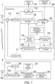
- Fig. 1 is a block diagram illustrating a configuration of a radar device 1 and a racon 3 according to one embodiment of the present disclosure.
- the radar device 1 illustrated in Fig. 1 is provided to a ship (not illustrated) as a movable body.
- the radar device 1 detects a target object therearound by transmitting from a radar antenna (antenna) 12 a detection signal which is a radio wave, and receiving a reflection wave by the radar antenna 12.
- the racon (transponder) 3 transmits a response signal which is a radio wave, from a racon antenna 32 to the radar device 1 in response to the detection signal of the radar device 1.
- This response signal includes positional information which expresses the position of the racon 3, for example, by latitude and longitude.
- the radar device 1 can obtain the position of the radar device 1 based on the response signal etc. of the racon 3.
- the racon 3 is described. As illustrated in Fig. 1 , the racon 3 includes a transmitter 31, the racon antenna 32, a circulator 33, a receiver 34, a positional information memory 35, a transmission waveform generator 36, and a standby time memory 37.
- the racon 3 includes a computer (not illustrated) which is provided with a CPU, a ROM, a RAM, etc.
- the ROM stores a suitable program which causes the racon 3 to transmit the response signal in response to the detection signal.
- the racon 3 is possible to function as the transmitter 31, the receiver 34, the positional information memory 35, the transmission waveform generator 36, the standby time memory 37, etc.
- the transmitter 31 outputs the response signal which responds the detection signal to the racon antenna 32 through the circulator 33, when the receiver 34 (described later) receives the detection signal from the radar device 1.
- the racon antenna 32 emits the response signal inputted from the transmitter 31 to the external device as the radio wave.
- the racon antenna 32 also receives the detection signal of the radar device 1.
- the circulator 33 outputs the response signal inputted from the transmitter 31 to the racon antenna 32.
- the circulator 33 also outputs the detection signal received by the racon antenna 32 to the receiver 34.
- the receiver 34 receives the detection signal from the racon antenna 32 through the circulator 33.
- the receiver 34 acquires a reception end timing of the detection signal, when it detects the detection signal.
- the reception end timing of the detection signal can be obtained by detecting a falling edge of a pulse, for example, when the detection signal is of a pulse shape.
- the receiver 34 outputs the acquired reception end timing of the detection signal to the transmitter 31.
- the positional information memory 35 is configured as a memory which stores the positional information of the racon 3 set beforehand, in detail, the latitude and longitude indicative of the position of the racon 3.
- the positional information memory 35 outputs the positional information of the racon 3 to the transmission waveform generator 36.
- the transmission waveform generator 36 generates a packet so as to include the positional information inputted from the positional information memory 35 and suitably modulates the packet to generate a waveform of the response signal to be transmitted from the transmitter 31.
- the transmission waveform generator 36 outputs the waveform of the generated response signal to the transmitter 31.
- the standby time memory 37 is configured as a memory which stores a timing at which the response signal is transmitted, in detail, a standby time from the racon 3 ending the reception of the detection signal to the response signal being transmitted.
- a suitable value as the standby time is set beforehand before the racon 3 is activated.
- the standby time memory 37 outputs the stored standby time to the transmitter 31.
- the transmitter 31 waits for the standby time stored in the standby time memory 37 from the reception end timing of the detection signal inputted from the receiver 34. At the same time as the completion of the standby, the transmitter 31 transmits the transmission waveform inputted from the transmission waveform generator 36 to the external device from the racon antenna 32 through the circulator 33, as the response signal.
- Fig. 2 is a packet structure chart of the response signal.
- Figs. 2(a) and 2(b) formats of the packets indicative of the response signal transmitted from the racon 3 are illustrated.
- Fig. 2(a) illustrates a packet in case of responding for latitude
- Fig. 2(b) illustrates a packet in case of responding for longitude.
- the response signal is a digital signal having a length of a total of 80 bits, where the leading 32 bits correspond to a preamble part, the subsequent 32 bits correspond to an information part, and the final 16 bits correspond to an error detector.
- the first half 16 bits of 32 bits correspond to a training sequence
- the second half 16 bits correspond to a start sequence.
- the training sequence is comprised of a bit stream where 0 and 1 appear alternately.
- the start sequence is comprised of a bit stream of M-sequence code which is a kind of a pseudo noise code.
- the information part is a part which describes information indicative of the position of the racon 3.
- the information part when responding for latitude, has a form in which a 27-bit bit stream indicative of a numerical value of the latitudinal is added after a 5-bit bit stream of "00000.”
- the information part when responding for longitude, has a form in which a 28-bit bit stream indicative of a numerical value of the longitude is added after a 4-bit bit stream of "1000.”
- the error detector is comprised of a 16-bit checksum value calculated by a method of known Cyclic Redundancy Check (CRC) to the contents of the information part.
- CRC Cyclic Redundancy Check
- the radar device 1 is described. As illustrated in Fig. 1 , the radar device 1 includes a transmitter 11, the radar antenna 12, a circulator 13, a receiver 14, an image generator 15, a response signal detector 16, a positional information acquirer 17, a racon direction acquirer 18, a response time acquirer 19, a racon reflection wave detector (transponder reflection wave detector) 20, a response delay acquirer 21, and a positioning part 22.
- the radar device 1 includes a transmitter 11, the radar antenna 12, a circulator 13, a receiver 14, an image generator 15, a response signal detector 16, a positional information acquirer 17, a racon direction acquirer 18, a response time acquirer 19, a racon reflection wave detector (transponder reflection wave detector) 20, a response delay acquirer 21, and a positioning part 22.
- the radar device 1 includes a computer (not illustrated), which is provided with a CPU, a ROM, a RAM, etc.
- the ROM stores a program for realizing a method of acquiring a racon response delay (described later) and a positioning method.
- the radar device 1 is possible to function as the transmitter 11, the receiver 14, the image generator 15, the response signal detector 16, the positional information acquirer 17, the racon direction acquirer 18, the response time acquirer 19, the racon reflection wave detector 20, the response delay acquirer 21, the positioning part 22, etc.
- the radar device 1 is electrically connected to a display part 91 and a direction sensor 92.
- the display part 91 is configured, for example, as a liquid crystal display, and is capable of displaying various kinds of information on a screen thereof.
- the direction sensor 92 is comprised of, for example, a magnetic direction sensor or a gyrocompass.
- the direction sensor 92 is attached to a suitable position of the ship, and is capable of detecting a bow direction (a direction in which the bow is directed) as an absolute azimuth based on the terrestrial reference.
- the transmitter 11 generates the detection signal. Although in this embodiment a semiconductor device is used as the transmitter 11, a magnetron may alternatively be used.
- the transmitter 11 amplifies the generated detection signal and outputs it to the radar antenna 12 through the circulator 13.
- the radar antenna 12 emits the detection signal inputted from the transmitter 11 to the external device as a radio wave, while swiveling in a horizontal plane at a given cycle. Moreover, the radar antenna 12 receives the reflection wave which is a reflection of the transmitted detection signal. In the following description, operation of transmitting a pulse-shaped detection signal once by the radar antenna 12 and receiving the reflection wave by the radar antenna 12 may be referred to as a "sweep.”
- the radar device 1 detects target objects therearound over 360° by repeating the sweep at a short time interval, while swiveling the radar antenna 12.
- the circulator 13 outputs the detection signal inputted from the transmitter 11 to the radar antenna 12.
- the circulator 13 also outputs the reflection wave received by the radar antenna 12 to the receiver 14 as a reception signal.
- the reception signal may include the response signal transmitted from the racon 3.
- the receiver 14 receives the reception signal from the radar antenna 12 through the circulator 13.
- the receiver 14 performs various kinds of signal processing to the inputted reception signal.
- the signal processing includes, but is not limited to, amplification.
- the receiver 14 outputs the processed reception signal to the image generator 15, the response signal detector 16, and the racon reflection wave detector 20.
- the image generator 15 performs various kinds of signal processing to the reception signal inputted from the receiver 14.
- the signal processing includes, but is not limited to, known clutter suppression, sensitivity adjustment, etc.
- the image generator 15 generates a radar image based on the processed signal.
- the image generator 15 displays the generated radar image on the display part 91 electrically connected to the radar device 1.
- the display part 91 may be configured, for example, as a liquid crystal display.
- the response signal detector 16 detects the response signal from the racon 3 based on the reception signal inputted from the receiver 14. If the response signal is detected based on the reception signal, the response signal detector 16 acquires a head timing of the response signal by a calculation.
- the response signal detector 16 outputs the detected response signal to the positional information acquirer 17.
- the response signal detector 16 also outputs to the racon direction acquirer 18 information indicative of whether the response signal from the racon 3 is included in the reception signal, each time the reception signal for one sweep is processed.
- the response signal detector 16 further outputs the head timing of the acquired response signal to the response time acquirer 19, the racon reflection wave detector 20, and the response delay acquirer 21, if the response signal is included in the processed reception signal.
- the positional information acquirer 17 demodulates the response signal inputted from the response signal detector 16 and extracting the contents of the information part illustrated in Fig. 2 to acquire the positional information included in the response signal, in detail, the latitude and longitude of the racon 3. At this time, the positional information acquirer 17 performs a CRC check based on the error detector at the end of the response signal to check whether there is an error in the contents of the obtained information part. The positional information acquirer 17 outputs the acquired positional information to the positioning part 22.
- the racon direction acquirer 18 acquires a relative direction of the racon 3 with respect to the radar device 1 based on the information inputted from the response signal detector 16.
- the relative direction can be obtained as an azimuth corresponding to the sweep which includes the response signal.
- the relative direction may be an azimuth which is obtained by equally dividing an azimuth range corresponding to the plurality of sweeps into two.
- the response time acquirer 19 acquires a time from the transmission of the detection signal from the radar antenna 12 to the reception of the response signal of the racon 3 (hereinafter, may be referred to as a "response time") based on the head timing of the response signal inputted from the response signal detector 16.
- the response time acquirer 19 outputs the acquired response time to the positioning part 22.
- the racon reflection wave detector 20 detects the reflection wave which appears at a timing earlier than the head timing of the response signal inputted from the response signal detector 16 as the reflection wave of the racon 3, from the reception signal inputted from the receiver 14.
- the racon reflection wave detector 20 outputs the reception timing of the detected reflection wave of the racon 3 to the response delay acquirer 21.
- the response delay acquirer 21 acquires the response delay of the racon 3 by calculating a time difference between the reception timing of the reflection wave of the racon 3 inputted from the racon reflection wave detector 20 and the head timing of the response signal inputted from the response signal detector 16.
- the response delay of the racon 3 is a time required from the reception of the detection signal by the racon 3 to the transmission of the response signal by the racon 3.
- the response delay acquirer 21 outputs the acquired response delay to the positioning part 22.
- the positioning part 22 finds the position of the radar device 1 (in detail, latitude and longitude) based on the response time obtained by the response time acquirer 19, the response delay obtained by the response delay acquirer 21, the relative direction of the racon 3 obtained by the racon direction acquirer 18, the absolute direction of the bow obtained by the direction sensor 92, and the positional information of the racon 3 obtained by the positional information acquirer 17.
- the positioning part 22 finds a time required for a signal going and coming back between the radar device 1 and the racon 3 (hereinafter, may be referred to as a "round-trip time") by subtracting the response delay obtained by the response delay acquirer 21 from the response time obtained by the response time acquirer 19.
- the distance between the radar device 1 and the racon 3 can be found by dividing the round-trip time by 2 and multiplying it by a speed of the radio wave.
- the absolute direction of the racon 3 when seen from the radar device 1 can be obtained based on the relative direction of the racon 3 with respect to the radar device 1 obtained by the racon direction acquirer 18 and the absolute direction of the bow obtained by the direction sensor 92.
- the positioning part 22 finds, by a calculation, the latitude and longitude of the radar device 1 based on the distance between the radar device 1 and the racon 3, the absolute direction of the racon 3 when seen from the radar device 1, and the latitude and longitude of the racon 3 obtained by the positional information acquirer 17. As described above, the positioning of the radar device 1 using the racon 3 is realized.
- the positioning part 22 outputs the obtained latitude and longitude of the radar device 1 to the image generator 15.
- the image generator 15 displays the positioning result of the positioning part 22 on the display part 91, together with a generated radar image.
- the display method of the positioning result the numerical values of the latitude and longitude may be displayed directly, or may be displayed by other methods. Therefore, a user of the radar device 1 can grasp the position of his/her ship by viewing the screen of the display part 91.
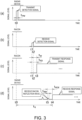
- Fig. 3 illustrates timing charts illustrating timings of transmission and reception of the radio wave performed between the radar device 1 and the racon 3.
- FIG. 3 illustrate, for a transmission and a reception of the radio wave for one sweep, timings of transmissions and receptions, sequentially from top, of the detection signal transmitted from the radar device 1, the detection signal received by the racon 3, the response signal transmitted from the racon 3, and the response signal received by the radar device 1.
- the vertical axis is a signal level and the horizontal axis is time. The times of the horizontal axis correspond to each other in the four charts.
- the racon 3 when the racon 3 receives the detection signal, it detects a time t2 which is a falling timing of the pulse-shaped detection signal. The racon 3 starts the transmission of the response signal at a time t3 after it waited for a standby time t w from the detected time t2. The response signal reaches the radar device 1 at a time t4 illustrated in Chart (d) of Fig. 3 and is received by the radar device 1.
- the response time acquirer 19 provided to the radar device 1 finds, for positioning, a response time t R which is a time difference between the time t0 at which the radar device 1 transmits the detection signal and the time t4 at which the radar device 1 receives the response signal.
- the response time t R includes a racon response delay t RD which is a time difference from the time t1 at which the detection signal reaches the racon 3 to the time t3 at which the racon 3 starts the transmission of the response signal.
- the racon response delay t RD is not unified although there is an upper limit in the standard, and therefore, the unknown response delay is a cause of deteriorating the positioning accuracy.
- the racon reflection wave detector 20 provided to the radar device 1 of this embodiment detects the reflection wave which appears at a timing earlier than the response signal in the reception signal, as the reflection wave which is a reflection of the detection signal on the racon 3. Then, the response delay acquirer 21 acquires a time difference between a time t5 at which the reflection wave of the racon 3 is received and the time t4 at which the response signal is received, as a racon response delay t RDE .
- the racon reflection wave detector 20 can detect the reflection wave of the racon 3 accurately, the racon response delay t RDE acquired by the response delay acquirer 21 must be in agreement with the actual racon response delay t RD .
- the radar device 1 of this embodiment can obtain the accurate positioning result by the positioning part 22 performing the calculation using the racon response delay t RDE .
- the racon reflection wave detector 20 detects only the reflection wave of which the time difference with the head timing (timing t4) of the response signal inputted from the response signal detector 16 is less than a given amount, as the reflection wave of the racon 3.
- the upper limit of the time difference may be a value obtained by adding a suitable margin to the upper limit according to the standard of the racon response delay described above. Therefore, the reflection wave of the racon 3 can appropriately be detected.
- the racon reflection wave detector 20 detects only the reflection wave of which the difference between a time t PW from a time when the reflection wave appears to a time when it disappears and the pulse width t PW which is the transmission time of the pulse-shaped detection signal is less than a given amount, as the reflection wave of the racon 3.
- the condition to be satisfied by the width of the reflection wave in order for it to be detected as the reflection wave of the racon 3 is a given range which includes the pulse width t PW of the detection signal. Therefore, the reflection wave of the racon 3 can be detected more accurately.
- the start sequence of the preamble part of the response signal is the 16-bit M-sequence code. Since this start sequence is known, the response signal detector 16 finds a correlation between the 16-bit signal which is a replica of the start sequence code, and the reception signal.
- a timing at which the replica becomes in agreement with the reception signal indicates the head of the information part subsequent to the start sequence.
- the response signal detector 16 detects a timing gone backward a period of time corresponding to 32 bits which is the length of the preamble part from a timing at which the correlation of the replica and the reception signal exceeds a given threshold, as the head timing (time t4 described above) of the response signal. Therefore, the head timing of the response signal can be obtained accurately.
- the radar device 1 of this embodiment includes the response signal detector 16, the racon reflection wave detector 20, and the response delay acquirer 21.
- the response signal detector 16 detects the response signal transmitted from the racon 3 in response to the detection signal, from the reception signal which is obtained by receiving the reflection wave of the detection signal transmitted from the radar antenna 12.
- the racon reflection wave detector 20 detects the reflection wave which appears at the timing earlier than the response signal in the reception signal, as the reflection wave of the racon 3.
- the response delay acquirer 21 acquires the response delay of the racon 3 based on the time difference between the reception timing of the reflection wave and the reception timing of the response signal.
- the radar device 1 of this embodiment acquires the response delay of the racon 3 by the following method. That is, the radio wave of the detection signal is transmitted from the radar antenna 12. The radar antenna 12 receives the reflection wave which is the reflection of the detection signal on the racon 3. The radar antenna 12 receives the response signal which is the radio wave transmitted from the racon 3 in response to the detection signal. The response delay of the racon 3 is acquired based on the time difference between the reception timing of the reflection wave and the reception timing of the response signal.
- the radar device 1 can instantly acquire the response delay based on the reflection wave and the response signal. Therefore, the distance between the radar device 1 and the racon 3 can accurately be acquired with the simple configuration.
- FIG. 4 illustrates charts illustrating a situation of one modification where an average is calculated from the reception signals for a plurality of sweeps, and the reflection wave of the racon is detected from the average. Note that, in the following description, description of configurations the same as or similar to those of the above embodiment may be omitted, while denoting the name of components with the same reference characters.
- the racon reflection wave detector 20 detects the reflection wave of the racon 3 from the reception signal for one sweep.
- the racon 3 since the detection signal is repeatedly transmitted, while the direction of the radar antenna 12 is changed little by little, the racon 3 often transmits the response signal corresponding to each of the plurality of sweeps, as illustrated in Fig. 4 . Therefore, in this modification, the racon reflection wave detector 20 performs average processing, which is a kind of statistical processing, for the signal levels of the reception signals of the plurality of sweeps which include the response signals, and detects the reflection wave of the racon 3 based on the obtained average value.
- Fig. 4 one example where an average waveform is calculated from the reception signals for three sweeps is illustrated, and it is found that the reflection wave resulted from noise becomes smaller in the average waveform, although it is conspicuous before the average calculation. Therefore, the reflection wave of the racon 3 can be detected more accurately.
- the electric power of the preamble part may be detected, and the detection of the head timing of the response signal may be performed based on a timing at which the detected electric power exceeds a given threshold, for example.
- the format of the response signal transmitted from the racon 3 may be arbitrary, instead of the formats illustrated in Figs. 2(a) and 2(b) .
- processing for calculating the average of the reception signals of a plurality of sweeps is performed.
- processings other than the averaging for example, processing for calculating a correlation between the reception signals of the plurality of sweeps, may also be performed.
- a reflector etc. may be attached to the racon 3 so that the detection signal from the radar device 1 is suitably reflected on the racon 3.
- the positioning by the radar device 1 and the racon 3 may be utilized independently, or may be utilized as an alternative means when positioning by other positioning devices (e.g., a GNSS positioning device) becomes impossible for a certain reason.
- other positioning devices e.g., a GNSS positioning device
Landscapes
- Engineering & Computer Science (AREA)
- Radar, Positioning & Navigation (AREA)
- Remote Sensing (AREA)
- Computer Networks & Wireless Communication (AREA)
- Physics & Mathematics (AREA)
- General Physics & Mathematics (AREA)
- Radar Systems Or Details Thereof (AREA)
Claims (6)
- Radarvorrichtung (1), aufweisend:einen Antwortsignal-Detektor (16), der so konfiguriert ist, dass er ein von einem Transponder (3) als Antwort auf ein Detektionssignal übertragenes Antwortsignal aus einem Empfangssignal detektiert, das eine empfangene Reflexionswelle des von einer Antenne (12) gesendeten Detektionssignals ist,einen Transponder-Reflexionswellen-Detektor (20), der so konfiguriert ist, dass er die Reflexionswelle, die zu einem früheren Zeitpunkt als das Antwortsignal im Empfangssignal erscheint, als die Reflexionswelle des Transponders (3) detektiert; undeine Positionsinformations-Erfassungsvorrichtung (17), die so konfiguriert ist, dass sie eine Positionsinformation, die eine Position des Transponders (3) angibt, aus dem durch den Antwortsignal-Detektor (16) detektierten Antwortsignal erfasst;gekennzeichnet durcheine Antwortverzögerungs-Erfassungsvorrichtung (21), die so konfiguriert ist, dass sie eine Antwortverzögerung des Transponders (3) basierend auf einer Zeitdifferenz zwischen einem Empfangszeitpunkt der Reflexionswelle und einem Empfangszeitpunkt des Antwortsignals erfasst, wobei die Radarvorrichtung ferner aufweist:eine Antwortzeit-Erfassungsvorrichtung (19), die so konfiguriert ist, dass sie eine Antwortzeit erfasst, die eine Zeit von der Übertragung des Detektionssignals bis zum Empfang des Antwortsignals ist; undeinen Positionsbestimmungsteil (22), der so konfiguriert ist, dass er eine Position der Radarvorrichtung (1) basierend auf der Positionsinformation, der Antwortzeit und der Antwortverzögerung erfasst.
- Radarvorrichtung (1) nach Anspruch 1, wobei der Transponder-Reflexionswellen-Detektor (20) die Reflexionswelle, die zu einem Zeitpunkt erscheint, zu dem eine Zeitdifferenz von einem Kopf-Zeitpunkt des Antwortsignals im Empfangssignal geringer als ein gegebener Betrag wird, als die Reflexionswelle des Transponders (3) detektiert.
- Radarvorrichtung (1) nach Anspruch 1 oder 2, wobei das Antwortsignal des Transponders (3) einen Pseudo-Rauschcode enthält und
wobei der Antwortsignal-Detektor (16) den Kopf-Zeitpunkt des Antwortsignals basierend auf einem Zeitpunkt erfasst, zu dem eine Korrelation des Empfangssignals und des Pseudo-Rauschcodes über einen gegebenen Umfang hinausgeht. - Radarvorrichtung (1) nach einem der Ansprüche 1 bis 3, wobei der Transponder-Reflexionswellen-Detektor (20) die Reflexionswelle aus den im Empfangssignal erscheinenden Reflexionswellen, deren Zeitdauer vom Erscheinen der Reflexionswelle im Empfangssignal bis zum Verschwinden der Reflexionswelle aus dem Empfangssignal innerhalb eines gegebenen Bereichs liegt, als die Reflexionswelle des Transponders (3) detektiert, und
wobei der gegebene Bereich eine Übertragungszeit des Detektionssignals mit einer Impulsform einschließt. - Radarvorrichtung (1) nach einem der Ansprüche 1 bis 4, wobei der Transponder-Reflexionswellen-Detektor (20) die Reflexionswelle des Transponders (3) durch Verarbeiten einer Vielzahl von Sweeps detektiert.
- Verfahren zum Erfassen einer Transponder-Antwortverzögerung, aufweisend die Schritte:Übertragen einer Funkwelle eines Detektionssignals von einer Antenne;Empfangen, mittels der Antenne, einer Reflexionswelle, bei der es sich um eine Reflexion des Detektionssignals an einem Transponder (3) handelt;Empfangen, mittels der Antenne, eines Antwortsignals, bei dem es sich um eine vom Transponder als Antwort auf das Detektionssignal übertragene Funkwelle handelt; undErfassen einer Positionsinformation, die eine Position des Transponders (3) angibt, aus dem empfangenen Antwortsignal;gekennzeichnet durchErfassen der Transponder-Antwortverzögerung basierend auf einer Zeitdifferenz zwischen einem Empfangszeitpunkt der Reflexionswelle und einem Empfangszeitpunkt des Antwortsignals,Erfassen einer Antwortzeit, bei der es sich um die Zeit von der Übertragung des Detektionssignals bis zum Empfang des Antwortsignals handelt; undErfassen einer Position der Radarvorrichtung (1) basierend auf der Positionsinformation, der Antwortzeit und der Antwortverzögerung.
Applications Claiming Priority (2)
| Application Number | Priority Date | Filing Date | Title |
|---|---|---|---|
| JP2017170695 | 2017-09-05 | ||
| PCT/JP2018/030718 WO2019049648A1 (ja) | 2017-09-05 | 2018-08-21 | レーダ装置、及びトランスポンダ応答遅延の取得方法 |
Publications (3)
| Publication Number | Publication Date |
|---|---|
| EP3680686A1 EP3680686A1 (de) | 2020-07-15 |
| EP3680686A4 EP3680686A4 (de) | 2021-06-02 |
| EP3680686B1 true EP3680686B1 (de) | 2023-10-04 |
Family
ID=65634066
Family Applications (1)
| Application Number | Title | Priority Date | Filing Date |
|---|---|---|---|
| EP18854856.4A Active EP3680686B1 (de) | 2017-09-05 | 2018-08-21 | Radarvorrichtung und verfahren zur erfassung der verzögerung einer transponderantwort |
Country Status (3)
| Country | Link |
|---|---|
| EP (1) | EP3680686B1 (de) |
| JP (2) | JP7018448B2 (de) |
| WO (1) | WO2019049648A1 (de) |
Families Citing this family (1)
| Publication number | Priority date | Publication date | Assignee | Title |
|---|---|---|---|---|
| JP2021085719A (ja) * | 2019-11-26 | 2021-06-03 | 株式会社Soken | デジタルキーシステムおよび車載システム |
Family Cites Families (12)
| Publication number | Priority date | Publication date | Assignee | Title |
|---|---|---|---|---|
| NO169267C (no) | 1989-06-08 | 1992-05-27 | Miros As | Fremgangsmaate ved system til deteksjon, lokalisering og klassifisering av maalobjekter |
| JPH04351987A (ja) * | 1991-05-30 | 1992-12-07 | Oki Electric Ind Co Ltd | パルスレーダによるデータ通信方法 |
| JPH0961518A (ja) * | 1995-08-23 | 1997-03-07 | Nec Corp | 二次レーダ装置 |
| JP2000019246A (ja) | 1998-07-03 | 2000-01-21 | Denso Corp | 障害物検知システム,レーダ装置,トランスポンダ |
| US6529156B2 (en) * | 2001-06-07 | 2003-03-04 | Itt Defense And Electronics | Self calibration of transponder apparatus |
| EP1732239A4 (de) | 2004-03-17 | 2007-12-26 | Brother Ind Ltd | Positionsdetektionssystem, antworteinrichtung und abfrageeinrichtung, funkkommunikationssystem, positionsdetektionsverfahren, positionsdetektionsprogramm und informationsaufzeichnungsmedium |
| JP4771790B2 (ja) * | 2005-11-08 | 2011-09-14 | 三菱電機株式会社 | デジタルrfメモリ装置 |
| JP2011145111A (ja) | 2010-01-12 | 2011-07-28 | Panasonic Corp | Uwbセンサシステム及びリーダ装置 |
| JP2013142661A (ja) | 2012-01-12 | 2013-07-22 | Furuno Electric Co Ltd | レーダ装置、レーダ測位システム、レーダ測位方法及びレーダ測位プログラム |
| JP6370121B2 (ja) * | 2014-06-11 | 2018-08-08 | 古野電気株式会社 | 自船位置測位装置、レーダ装置、自移動体位置測位装置及び自船位置測位方法 |
| CA2989702A1 (en) * | 2015-06-15 | 2016-12-22 | Humatics Corporation | High-precision time of flight measurement system |
| JP6271475B2 (ja) * | 2015-07-22 | 2018-01-31 | 格一 塩見 | 反射型レーダ受信機 |
-
2018
- 2018-08-21 EP EP18854856.4A patent/EP3680686B1/de active Active
- 2018-08-21 JP JP2019540866A patent/JP7018448B2/ja active Active
- 2018-08-21 WO PCT/JP2018/030718 patent/WO2019049648A1/ja not_active Ceased
-
2022
- 2022-01-28 JP JP2022012167A patent/JP7379551B2/ja active Active
Also Published As
| Publication number | Publication date |
|---|---|
| JP7018448B2 (ja) | 2022-02-10 |
| EP3680686A1 (de) | 2020-07-15 |
| JP7379551B2 (ja) | 2023-11-14 |
| WO2019049648A1 (ja) | 2019-03-14 |
| JP2022051800A (ja) | 2022-04-01 |
| JPWO2019049648A1 (ja) | 2020-10-15 |
| EP3680686A4 (de) | 2021-06-02 |
Similar Documents
| Publication | Publication Date | Title |
|---|---|---|
| EP2787364A2 (de) | Funkbakenstationen, Benutzervorrichtungen, Standortbestimmungssysteme, Verfahren zur Steuerung einer Funkbakenstation, Verfahren zur Steuerung einer Benutzervorrichtung und Standortbestimmungsverfahren | |
| US12235340B2 (en) | Distance measurement device and distance measurement method | |
| JP2010060303A (ja) | 測位装置 | |
| JP6546109B2 (ja) | レーダ装置 | |
| JP6324327B2 (ja) | パッシブレーダ装置 | |
| EP3680686B1 (de) | Radarvorrichtung und verfahren zur erfassung der verzögerung einer transponderantwort | |
| JP2009270863A (ja) | バイスタティックレーダ装置 | |
| EP2913690B1 (de) | Positionierungssystem und Verfahren | |
| RU2235342C2 (ru) | Способ измерения угловых координат объекта и радиолокационная станция для его реализации | |
| RU2444748C2 (ru) | Способ определения дальности до излучающей обзорной радиолокационной станции | |
| JP3484995B2 (ja) | 瞬時パッシブ距離測定装置 | |
| JP2004264070A (ja) | バイスタティック方位検出システム及び検出方法 | |
| US20040150560A1 (en) | Positioning system and method | |
| US12035271B2 (en) | System and method for detecting and locating a signal source | |
| JP2865082B2 (ja) | 電波受信装置 | |
| JP2013024775A (ja) | レーダ装置 | |
| JP6989663B1 (ja) | レーダ装置 | |
| KR102870941B1 (ko) | Gnss 기만 장치, 방법 및 시스템 | |
| JP2007192573A (ja) | 目標測位装置 | |
| JP2012202698A (ja) | 時間差方位探知装置 | |
| US11226394B2 (en) | Direction finding system and method for radio direction finding of a target | |
| JPH09257907A (ja) | 物標映像の方位算出方法及び装置 | |
| JP2000241543A (ja) | 移動体移動量検出装置 | |
| KR101238321B1 (ko) | 물체의 거리 측정 시스템 | |
| JP2015190784A (ja) | レーダ装置 |
Legal Events
| Date | Code | Title | Description |
|---|---|---|---|
| STAA | Information on the status of an ep patent application or granted ep patent |
Free format text: STATUS: THE INTERNATIONAL PUBLICATION HAS BEEN MADE |
|
| PUAI | Public reference made under article 153(3) epc to a published international application that has entered the european phase |
Free format text: ORIGINAL CODE: 0009012 |
|
| STAA | Information on the status of an ep patent application or granted ep patent |
Free format text: STATUS: REQUEST FOR EXAMINATION WAS MADE |
|
| 17P | Request for examination filed |
Effective date: 20200331 |
|
| AK | Designated contracting states |
Kind code of ref document: A1 Designated state(s): AL AT BE BG CH CY CZ DE DK EE ES FI FR GB GR HR HU IE IS IT LI LT LU LV MC MK MT NL NO PL PT RO RS SE SI SK SM TR |
|
| AX | Request for extension of the european patent |
Extension state: BA ME |
|
| DAV | Request for validation of the european patent (deleted) | ||
| DAX | Request for extension of the european patent (deleted) | ||
| A4 | Supplementary search report drawn up and despatched |
Effective date: 20210430 |
|
| RIC1 | Information provided on ipc code assigned before grant |
Ipc: G01S 13/74 20060101AFI20210423BHEP Ipc: G01S 7/292 20060101ALI20210423BHEP Ipc: G01S 13/87 20060101ALI20210423BHEP |
|
| RIC1 | Information provided on ipc code assigned before grant |
Ipc: G01S 7/292 20060101ALI20230222BHEP Ipc: G01S 13/87 20060101ALI20230222BHEP Ipc: G01S 13/76 20060101ALI20230222BHEP Ipc: G01S 13/74 20060101AFI20230222BHEP |
|
| GRAP | Despatch of communication of intention to grant a patent |
Free format text: ORIGINAL CODE: EPIDOSNIGR1 |
|
| STAA | Information on the status of an ep patent application or granted ep patent |
Free format text: STATUS: GRANT OF PATENT IS INTENDED |
|
| INTG | Intention to grant announced |
Effective date: 20230403 |
|
| GRAS | Grant fee paid |
Free format text: ORIGINAL CODE: EPIDOSNIGR3 |
|
| GRAA | (expected) grant |
Free format text: ORIGINAL CODE: 0009210 |
|
| STAA | Information on the status of an ep patent application or granted ep patent |
Free format text: STATUS: THE PATENT HAS BEEN GRANTED |
|
| AK | Designated contracting states |
Kind code of ref document: B1 Designated state(s): AL AT BE BG CH CY CZ DE DK EE ES FI FR GB GR HR HU IE IS IT LI LT LU LV MC MK MT NL NO PL PT RO RS SE SI SK SM TR |
|
| REG | Reference to a national code |
Ref country code: GB Ref legal event code: FG4D |
|
| REG | Reference to a national code |
Ref country code: CH Ref legal event code: EP |
|
| REG | Reference to a national code |
Ref country code: DE Ref legal event code: R096 Ref document number: 602018058870 Country of ref document: DE |
|
| REG | Reference to a national code |
Ref country code: IE Ref legal event code: FG4D |
|
| REG | Reference to a national code |
Ref country code: LT Ref legal event code: MG9D |
|
| REG | Reference to a national code |
Ref country code: NL Ref legal event code: MP Effective date: 20231004 |
|
| REG | Reference to a national code |
Ref country code: AT Ref legal event code: MK05 Ref document number: 1618286 Country of ref document: AT Kind code of ref document: T Effective date: 20231004 |
|
| PG25 | Lapsed in a contracting state [announced via postgrant information from national office to epo] |
Ref country code: NL Free format text: LAPSE BECAUSE OF FAILURE TO SUBMIT A TRANSLATION OF THE DESCRIPTION OR TO PAY THE FEE WITHIN THE PRESCRIBED TIME-LIMIT Effective date: 20231004 |
|
| PG25 | Lapsed in a contracting state [announced via postgrant information from national office to epo] |
Ref country code: GR Free format text: LAPSE BECAUSE OF FAILURE TO SUBMIT A TRANSLATION OF THE DESCRIPTION OR TO PAY THE FEE WITHIN THE PRESCRIBED TIME-LIMIT Effective date: 20240105 |
|
| PG25 | Lapsed in a contracting state [announced via postgrant information from national office to epo] |
Ref country code: IS Free format text: LAPSE BECAUSE OF FAILURE TO SUBMIT A TRANSLATION OF THE DESCRIPTION OR TO PAY THE FEE WITHIN THE PRESCRIBED TIME-LIMIT Effective date: 20240204 |
|
| PG25 | Lapsed in a contracting state [announced via postgrant information from national office to epo] |
Ref country code: LT Free format text: LAPSE BECAUSE OF FAILURE TO SUBMIT A TRANSLATION OF THE DESCRIPTION OR TO PAY THE FEE WITHIN THE PRESCRIBED TIME-LIMIT Effective date: 20231004 |
|
| PG25 | Lapsed in a contracting state [announced via postgrant information from national office to epo] |
Ref country code: AT Free format text: LAPSE BECAUSE OF FAILURE TO SUBMIT A TRANSLATION OF THE DESCRIPTION OR TO PAY THE FEE WITHIN THE PRESCRIBED TIME-LIMIT Effective date: 20231004 |
|
| PG25 | Lapsed in a contracting state [announced via postgrant information from national office to epo] |
Ref country code: ES Free format text: LAPSE BECAUSE OF FAILURE TO SUBMIT A TRANSLATION OF THE DESCRIPTION OR TO PAY THE FEE WITHIN THE PRESCRIBED TIME-LIMIT Effective date: 20231004 |
|
| PG25 | Lapsed in a contracting state [announced via postgrant information from national office to epo] |
Ref country code: LT Free format text: LAPSE BECAUSE OF FAILURE TO SUBMIT A TRANSLATION OF THE DESCRIPTION OR TO PAY THE FEE WITHIN THE PRESCRIBED TIME-LIMIT Effective date: 20231004 Ref country code: IS Free format text: LAPSE BECAUSE OF FAILURE TO SUBMIT A TRANSLATION OF THE DESCRIPTION OR TO PAY THE FEE WITHIN THE PRESCRIBED TIME-LIMIT Effective date: 20240204 Ref country code: GR Free format text: LAPSE BECAUSE OF FAILURE TO SUBMIT A TRANSLATION OF THE DESCRIPTION OR TO PAY THE FEE WITHIN THE PRESCRIBED TIME-LIMIT Effective date: 20240105 Ref country code: ES Free format text: LAPSE BECAUSE OF FAILURE TO SUBMIT A TRANSLATION OF THE DESCRIPTION OR TO PAY THE FEE WITHIN THE PRESCRIBED TIME-LIMIT Effective date: 20231004 Ref country code: BG Free format text: LAPSE BECAUSE OF FAILURE TO SUBMIT A TRANSLATION OF THE DESCRIPTION OR TO PAY THE FEE WITHIN THE PRESCRIBED TIME-LIMIT Effective date: 20240104 Ref country code: AT Free format text: LAPSE BECAUSE OF FAILURE TO SUBMIT A TRANSLATION OF THE DESCRIPTION OR TO PAY THE FEE WITHIN THE PRESCRIBED TIME-LIMIT Effective date: 20231004 Ref country code: PT Free format text: LAPSE BECAUSE OF FAILURE TO SUBMIT A TRANSLATION OF THE DESCRIPTION OR TO PAY THE FEE WITHIN THE PRESCRIBED TIME-LIMIT Effective date: 20240205 |
|
| PG25 | Lapsed in a contracting state [announced via postgrant information from national office to epo] |
Ref country code: SE Free format text: LAPSE BECAUSE OF FAILURE TO SUBMIT A TRANSLATION OF THE DESCRIPTION OR TO PAY THE FEE WITHIN THE PRESCRIBED TIME-LIMIT Effective date: 20231004 Ref country code: RS Free format text: LAPSE BECAUSE OF FAILURE TO SUBMIT A TRANSLATION OF THE DESCRIPTION OR TO PAY THE FEE WITHIN THE PRESCRIBED TIME-LIMIT Effective date: 20231004 Ref country code: PL Free format text: LAPSE BECAUSE OF FAILURE TO SUBMIT A TRANSLATION OF THE DESCRIPTION OR TO PAY THE FEE WITHIN THE PRESCRIBED TIME-LIMIT Effective date: 20231004 Ref country code: NO Free format text: LAPSE BECAUSE OF FAILURE TO SUBMIT A TRANSLATION OF THE DESCRIPTION OR TO PAY THE FEE WITHIN THE PRESCRIBED TIME-LIMIT Effective date: 20240104 Ref country code: LV Free format text: LAPSE BECAUSE OF FAILURE TO SUBMIT A TRANSLATION OF THE DESCRIPTION OR TO PAY THE FEE WITHIN THE PRESCRIBED TIME-LIMIT Effective date: 20231004 Ref country code: HR Free format text: LAPSE BECAUSE OF FAILURE TO SUBMIT A TRANSLATION OF THE DESCRIPTION OR TO PAY THE FEE WITHIN THE PRESCRIBED TIME-LIMIT Effective date: 20231004 |
|
| REG | Reference to a national code |
Ref country code: DE Ref legal event code: R097 Ref document number: 602018058870 Country of ref document: DE |
|
| PG25 | Lapsed in a contracting state [announced via postgrant information from national office to epo] |
Ref country code: DK Free format text: LAPSE BECAUSE OF FAILURE TO SUBMIT A TRANSLATION OF THE DESCRIPTION OR TO PAY THE FEE WITHIN THE PRESCRIBED TIME-LIMIT Effective date: 20231004 |
|
| PG25 | Lapsed in a contracting state [announced via postgrant information from national office to epo] |
Ref country code: CZ Free format text: LAPSE BECAUSE OF FAILURE TO SUBMIT A TRANSLATION OF THE DESCRIPTION OR TO PAY THE FEE WITHIN THE PRESCRIBED TIME-LIMIT Effective date: 20231004 |
|
| PG25 | Lapsed in a contracting state [announced via postgrant information from national office to epo] |
Ref country code: SK Free format text: LAPSE BECAUSE OF FAILURE TO SUBMIT A TRANSLATION OF THE DESCRIPTION OR TO PAY THE FEE WITHIN THE PRESCRIBED TIME-LIMIT Effective date: 20231004 |
|
| PG25 | Lapsed in a contracting state [announced via postgrant information from national office to epo] |
Ref country code: SM Free format text: LAPSE BECAUSE OF FAILURE TO SUBMIT A TRANSLATION OF THE DESCRIPTION OR TO PAY THE FEE WITHIN THE PRESCRIBED TIME-LIMIT Effective date: 20231004 Ref country code: SK Free format text: LAPSE BECAUSE OF FAILURE TO SUBMIT A TRANSLATION OF THE DESCRIPTION OR TO PAY THE FEE WITHIN THE PRESCRIBED TIME-LIMIT Effective date: 20231004 Ref country code: RO Free format text: LAPSE BECAUSE OF FAILURE TO SUBMIT A TRANSLATION OF THE DESCRIPTION OR TO PAY THE FEE WITHIN THE PRESCRIBED TIME-LIMIT Effective date: 20231004 Ref country code: IT Free format text: LAPSE BECAUSE OF FAILURE TO SUBMIT A TRANSLATION OF THE DESCRIPTION OR TO PAY THE FEE WITHIN THE PRESCRIBED TIME-LIMIT Effective date: 20231004 Ref country code: EE Free format text: LAPSE BECAUSE OF FAILURE TO SUBMIT A TRANSLATION OF THE DESCRIPTION OR TO PAY THE FEE WITHIN THE PRESCRIBED TIME-LIMIT Effective date: 20231004 Ref country code: DK Free format text: LAPSE BECAUSE OF FAILURE TO SUBMIT A TRANSLATION OF THE DESCRIPTION OR TO PAY THE FEE WITHIN THE PRESCRIBED TIME-LIMIT Effective date: 20231004 Ref country code: CZ Free format text: LAPSE BECAUSE OF FAILURE TO SUBMIT A TRANSLATION OF THE DESCRIPTION OR TO PAY THE FEE WITHIN THE PRESCRIBED TIME-LIMIT Effective date: 20231004 |
|
| PLBE | No opposition filed within time limit |
Free format text: ORIGINAL CODE: 0009261 |
|
| STAA | Information on the status of an ep patent application or granted ep patent |
Free format text: STATUS: NO OPPOSITION FILED WITHIN TIME LIMIT |
|
| 26N | No opposition filed |
Effective date: 20240705 |
|
| PG25 | Lapsed in a contracting state [announced via postgrant information from national office to epo] |
Ref country code: SI Free format text: LAPSE BECAUSE OF FAILURE TO SUBMIT A TRANSLATION OF THE DESCRIPTION OR TO PAY THE FEE WITHIN THE PRESCRIBED TIME-LIMIT Effective date: 20231004 |
|
| PG25 | Lapsed in a contracting state [announced via postgrant information from national office to epo] |
Ref country code: SI Free format text: LAPSE BECAUSE OF FAILURE TO SUBMIT A TRANSLATION OF THE DESCRIPTION OR TO PAY THE FEE WITHIN THE PRESCRIBED TIME-LIMIT Effective date: 20231004 |
|
| REG | Reference to a national code |
Ref country code: CH Ref legal event code: PL |
|
| PG25 | Lapsed in a contracting state [announced via postgrant information from national office to epo] |
Ref country code: LU Free format text: LAPSE BECAUSE OF NON-PAYMENT OF DUE FEES Effective date: 20240821 |
|
| PG25 | Lapsed in a contracting state [announced via postgrant information from national office to epo] |
Ref country code: MC Free format text: LAPSE BECAUSE OF FAILURE TO SUBMIT A TRANSLATION OF THE DESCRIPTION OR TO PAY THE FEE WITHIN THE PRESCRIBED TIME-LIMIT Effective date: 20231004 Ref country code: CH Free format text: LAPSE BECAUSE OF NON-PAYMENT OF DUE FEES Effective date: 20240831 |
|
| REG | Reference to a national code |
Ref country code: BE Ref legal event code: MM Effective date: 20240831 |
|
| PG25 | Lapsed in a contracting state [announced via postgrant information from national office to epo] |
Ref country code: BE Free format text: LAPSE BECAUSE OF NON-PAYMENT OF DUE FEES Effective date: 20240831 |
|
| PG25 | Lapsed in a contracting state [announced via postgrant information from national office to epo] |
Ref country code: IE Free format text: LAPSE BECAUSE OF NON-PAYMENT OF DUE FEES Effective date: 20240821 |
|
| PG25 | Lapsed in a contracting state [announced via postgrant information from national office to epo] |
Ref country code: FI Free format text: LAPSE BECAUSE OF FAILURE TO SUBMIT A TRANSLATION OF THE DESCRIPTION OR TO PAY THE FEE WITHIN THE PRESCRIBED TIME-LIMIT Effective date: 20231004 |
|
| PGFP | Annual fee paid to national office [announced via postgrant information from national office to epo] |
Ref country code: DE Payment date: 20250702 Year of fee payment: 8 |
|
| PGFP | Annual fee paid to national office [announced via postgrant information from national office to epo] |
Ref country code: GB Payment date: 20250703 Year of fee payment: 8 |
|
| PGFP | Annual fee paid to national office [announced via postgrant information from national office to epo] |
Ref country code: FR Payment date: 20250703 Year of fee payment: 8 |
|
| PG25 | Lapsed in a contracting state [announced via postgrant information from national office to epo] |
Ref country code: CY Free format text: LAPSE BECAUSE OF FAILURE TO SUBMIT A TRANSLATION OF THE DESCRIPTION OR TO PAY THE FEE WITHIN THE PRESCRIBED TIME-LIMIT; INVALID AB INITIO Effective date: 20180821 |
|
| PG25 | Lapsed in a contracting state [announced via postgrant information from national office to epo] |
Ref country code: HU Free format text: LAPSE BECAUSE OF FAILURE TO SUBMIT A TRANSLATION OF THE DESCRIPTION OR TO PAY THE FEE WITHIN THE PRESCRIBED TIME-LIMIT; INVALID AB INITIO Effective date: 20180821 |