EP3678858B1 - Verfahren und vorrichtung zur handhabung von fehlern in einer warenbahn einer verarbeitungsanlage - Google Patents
Verfahren und vorrichtung zur handhabung von fehlern in einer warenbahn einer verarbeitungsanlage Download PDFInfo
- Publication number
- EP3678858B1 EP3678858B1 EP19769214.8A EP19769214A EP3678858B1 EP 3678858 B1 EP3678858 B1 EP 3678858B1 EP 19769214 A EP19769214 A EP 19769214A EP 3678858 B1 EP3678858 B1 EP 3678858B1
- Authority
- EP
- European Patent Office
- Prior art keywords
- web material
- defects
- defect
- control unit
- conversion line
- Prior art date
- Legal status (The legal status is an assumption and is not a legal conclusion. Google has not performed a legal analysis and makes no representation as to the accuracy of the status listed.)
- Active
Links
Images


Classifications
-
- B—PERFORMING OPERATIONS; TRANSPORTING
- B31—MAKING ARTICLES OF PAPER, CARDBOARD OR MATERIAL WORKED IN A MANNER ANALOGOUS TO PAPER; WORKING PAPER, CARDBOARD OR MATERIAL WORKED IN A MANNER ANALOGOUS TO PAPER
- B31B—MAKING CONTAINERS OF PAPER, CARDBOARD OR MATERIAL WORKED IN A MANNER ANALOGOUS TO PAPER
- B31B70/00—Making flexible containers, e.g. envelopes or bags
- B31B70/006—Controlling; Regulating; Measuring; Safety measures
-
- B—PERFORMING OPERATIONS; TRANSPORTING
- B31—MAKING ARTICLES OF PAPER, CARDBOARD OR MATERIAL WORKED IN A MANNER ANALOGOUS TO PAPER; WORKING PAPER, CARDBOARD OR MATERIAL WORKED IN A MANNER ANALOGOUS TO PAPER
- B31B—MAKING CONTAINERS OF PAPER, CARDBOARD OR MATERIAL WORKED IN A MANNER ANALOGOUS TO PAPER
- B31B70/00—Making flexible containers, e.g. envelopes or bags
- B31B70/02—Feeding or positioning sheets, blanks or webs
- B31B70/10—Feeding or positioning webs
-
- B—PERFORMING OPERATIONS; TRANSPORTING
- B31—MAKING ARTICLES OF PAPER, CARDBOARD OR MATERIAL WORKED IN A MANNER ANALOGOUS TO PAPER; WORKING PAPER, CARDBOARD OR MATERIAL WORKED IN A MANNER ANALOGOUS TO PAPER
- B31B—MAKING CONTAINERS OF PAPER, CARDBOARD OR MATERIAL WORKED IN A MANNER ANALOGOUS TO PAPER
- B31B70/00—Making flexible containers, e.g. envelopes or bags
- B31B70/14—Cutting, e.g. perforating, punching, slitting or trimming
- B31B70/16—Cutting webs
-
- G—PHYSICS
- G01—MEASURING; TESTING
- G01N—INVESTIGATING OR ANALYSING MATERIALS BY DETERMINING THEIR CHEMICAL OR PHYSICAL PROPERTIES
- G01N21/00—Investigating or analysing materials by the use of optical means, i.e. using sub-millimetre waves, infrared, visible or ultraviolet light
- G01N21/84—Systems specially adapted for particular applications
- G01N2021/8411—Application to online plant, process monitoring
-
- G—PHYSICS
- G01—MEASURING; TESTING
- G01N—INVESTIGATING OR ANALYSING MATERIALS BY DETERMINING THEIR CHEMICAL OR PHYSICAL PROPERTIES
- G01N21/00—Investigating or analysing materials by the use of optical means, i.e. using sub-millimetre waves, infrared, visible or ultraviolet light
- G01N21/84—Systems specially adapted for particular applications
- G01N21/88—Investigating the presence of flaws or contamination
- G01N21/8851—Scan or image signal processing specially adapted therefor, e.g. for scan signal adjustment, for detecting different kinds of defects, for compensating for structures, markings, edges
- G01N2021/8854—Grading and classifying of flaws
- G01N2021/888—Marking defects
Definitions
- the invention relates to a device for managing defects in a web material on conversion lines.
- the device relates to identifying defective sections of web/web material and rejecting the defective pieces before they enter the downstream processes of a conversion line, such as bag making.
- Web material bags for the packaging of particulate goods such as, for example, cement have to be sufficiently firm and dust-tight in order to prevent contamination or exit of particles, respectively, during the process of filling, storage as well as transportation and, hence, also contribute to the protection of the environment.
- Web material bags for the packaging of free-flowing chemicals furthermore, have to meet in addition strict requirements in terms of occupational safety as well as requirements regarding the resistance of the material used against weather influences.
- the web material may have various defects along its length. Defects may include weaving defects, holes or surface defects, uneven coating edges, web material ends stuck together, printing defects, or other similar defects. Some defects may be of cosmetic nature; however some others may compromise integrity and strength of the web/web material or affect its other desirable properties such as leak-proofness, ultimately rendering it unsuitable for the purpose for which is designed. Downstream processing of the defected web/web material results in defected bags which need rejecting. Worse still, if such defected bags do not get rejected, they may be filled with material leading to spillage and wastage of material
- Producers and traders, respectively, of packaging bags made of web material are increasingly facing the problem that operators of automated filling plants detect a flawed bag in the course of incoming goods inspections on a random basis, so that a complete pallet or charge of hundreds or thousands of plastic bags will be reclaimed and will have to be taken back by the supplier.
- the economic damage arising thereof is tremendous.
- WO 2018/055856 A1 relates to a device and method for eliminating a defective sheet in plate-shaped cardboard sheets in which at least a bottom liner, a corrugated medium paper, and a top liner are bonded together and an apparatus for manufacturing a cardboard sheet, which is provided with the device for eliminating a defective sheet.
- WO 2005/085813 A1 relates to a device for monitoring a moving web of material at a textile machine, wherein a line sensor is arranged for scanning the web of material along its width.
- a sensor signal of the line sensor for example a CCD-opto-electric line sensor, is then processed by an electronic circuit into a configurable starting signal that triggers an action.
- Such a starting signal is suited to trigger, for example, the shut-down of the drive means for the web of material or the initiation of an optical or acoustic alarm.
- DE 33 04 817 A1 discloses a method for automatically detecting flaws in textile web materials using image filtration in order to increase the contrast between the global texture that is considered normal for the textile to be examined and the local deviations that are considered as flawed. Therefore, there are used at least two spatial filters for image transformation that are adjusted to the detection of straight-lined contour elements. Error signals obtained via digital image filtration are thus stored and analyzed by a down-stream processor.
- a coloured marking of a defect for example at a flat web of material, which in the subsequent process steps of the bag production is formed or closed, respectively, into a web material tube, may thus later on be situated on the inside of this web material tube and will thus not be detected in a down-stream optical quality control.
- the same is effective for coloured marks which, if the plastic webs in the course later on are printed on, will not be detectable anymore.
- defect sizes are to be eliminated. Large-scale or long defects occurring along several metres of a section of the plastic woven web material are more prone to be detected by the operating personnel than small-scale defects.
- an inspection camera for taking images of the plastic woven web material, and an analysis unit, which detects irregularities in the weaving pattern of the plastic woven web material on the basis of the images taken by the inspection camera and which, when detecting irregularities in the weaving pattern indicating a defected section of the plastic woven web material, triggers an error signal, which actuates, for example, a flashing light or a horn, or which can be fed to a higher-level machine controller.
- an inspection system for monitoring defects of a plastic woven web material as well as variants of a method for labelling or monitoring, respectively, defects of a plastic woven web material.
- a drawback of this approach is that labelling of defected areas of web material on a high speed processing unit is a cumbersome and complex operation. Also, further processing of the areas of web material identified as defective, particularly separating them from the defect-free sections is manual - which will involve stoppage of the advancing web.
- a further need of the state of the art is to provide a device that can identify the web material cut pieces which contain the detected defects and send them to a rejects collection zone without allowing them to enter the downstream bag manufacture units.
- One object of the invention is to provide a defect management device which identifies structural defects and defects of printing in advancing web material.
- Another object of the invention is to provide a defect management device that registers the defective stretches of the advancing web material in a database and physically separates them from defect-free web material.
- a further object of the invention is to separate the defective web material from the defect-free web material without stopping the advancing web material.
- a further object of the invention is to provide the management device at any location before a transverse cut is made in the web material.
- the invention relates to a device to manage defects (defects management device) in advancing web material provided on a conversion line, said device comprising the features of claim 1.
- Said conversion line having processing stations for making bags from said web material, said processing stations comprising at least one or more combinations of any of following units like a cutting station, a folding station, a base opening station, a base closing station, a coversheet station, a valve-making station, a stitching/seaming/sealing station, a stacking station.
- the defects management device comprises a defects detection unit, and a defects management control unit which monitor progress of the defect on the traveling web material and subsequently identifies the section of the of web material containing the defect to be cut, the defects management control unit also communicates with:
- the cut pieces of defects-free material proceed on to a transport table and are taken to the various further processing stations of the device.
- the invention further relates to a method to manage defects in advancing web material provided on a conversion line, the method comprising the features of claim
- a system/device and method of web material defects management which comprises detection of defects and of separating the defective areas of web material from defect-free web material without stopping the advancing web material is provided such that it overcomes the known disadvantages of the prior arts web inspection system.
- the device of the invention is suitable for detecting defects in a web material like plastic woven web material made of monoaxially drawn polymer ribbons, in particular polyolefin ribbons, preferably polypropylene ribbons, which is optionally coated with a thermoplastic material on one or two sides, it may be also optionally be printed or laminated with printed film or any combination thereof wherein in order to monitor irregularities, which are characteristic of defected sections of a typical plastic woven web material.
- the device/method also identifies cut pieces of the web material which contain the detected defects and sends them to a rejects collection zone without allowing them to enter the downstream bag manufacture units or the conversion line.
- a reliable device to detect and manage defects in web material (1) (defects detection and management system or device) is disclosed. It is provided on a conversion line, said conversion line having processing stations for making bags from said web material (1), said processing stations may be comprising at least one of following unit/station like, web unwinding station, cutting station, a folding station, a base opening station, a base closing station, a coversheet station, a valve-making station, a stitching station or a sealing station, characterised in that said device comprises a defects detection unit, and a defects management control unit which monitors progress of the defect on the traveling web material (1) and subsequently identifies the section of the of web material (1) containing the defect to be cut, the defects management control unit also communicates with:
- the defects management device (3) of the invention includes a unit (3) to detect defects and a defects management control unit (5) that manages defects on the traveling web material (1).
- the defects management device (3) of the invention is provided within a typical automated bag conversion line (6) where storage bags or sacks are made from flat or tube type web material (1).
- the defects management device (3) of the invention may also be provided on any conversion line (6) to make products from a flat or tubular web.
- the final product may be bags or simply cut pieces of web material (1). The cut pieces (1b) of defects-free material proceed on to a transport table (17) and are taken to the various further processing stations of the device.
- the defects detection unit (4) may include camera/infrared sensors/thickness sensors or even image processing devices that serve as a light sensing device (12).
- the defects management control unit (5) comprises controls that registers the detected defects (2) in a database (3a), calculates the time of their detection and, calculates and stores the positions of the defects (2) along the traveling web where transverse cuts need to be made to convert the web material (1) into pieces. According to the speed of travel of the web material (1), the defects management control unit (5) calculates the speed and position of the traveling defects (2). According to the type of the web material (1) - i.e. printed or plain, and the final product requirement, the defects management control unit (5) calculates the position of the transverse cuts to be made in the web material (1).
- the printing may carry a print design pattern or unpatterned design.
- the conversion line (6) may include a rejection system where the pieces (1c) of the web material (1) identified as defective are separated from the flow of the defect-free pieces (1b) so that the downstream product-making processes of the conversion line (6) may take place uninterrupted or without problems.
- the web defects management device (3) of the invention allows the process of detection of defects (2) and cutting the web material (1) into pieces without stopping the traveling web material (1).
- the term defects management includes tasks such as identification of defects, calculating and monitoring their location along the travelling web (1), monitoring and controlling the movement of the cutter of the bag conversion line (6) on which the web material (1) is processed into final product, separating the defective pieces (1c) of the web material (1) from the defect-free pieces (1b) of the web material (1).
- defect (2) refers to any unacceptable irregularities in the web material (1) from the perspective of the suitability for purpose for which the web material (1) is intended.
- Defects (2) may be uneven thickness variation, holes, uneven pattern, missing warp end, missing weft; crushing of weft; uneven coating edge trim, web joints, one or more layer of web; foreign particles, or any combination of these defects.
- web material web and fabric are used interchangeably in the following description.
- the web material (1) may be in the form of plastic film, non-woven material, paper, woven web material, woven plastic web material, or a composite material made from any of these materials. It may also be coated or laminated with plain or printed film, or printed, or any combination of thereof.
- Web materials - either in flat form or tubular form - are used for many purposes including making storage bags.
- Storage bags are typically made using an automatic or semi-automatic web conversion lines (6) (which converts web materials into bags). These systems may have any or all of the individual machines such as a cutting machine, folding/forming machine, stitching machine, valve forming machine.
- the conversion lines (6) may also include block bottom bag making or pouching forming machines.
- the web material defects management device (3) may be adapted by a person skilled in the art for use in any of these conversion systems. In particular, the placement of the device of invention on any of these conversion systems may be according to the choice of the user, although it is preferable that it is placed upstream of a cutting operation.
- the bag conversion lines or any other conversion lines that make products using web materials (1) may also have individual stations to perform operations such as making perforations or holes, joining, folding operations.
- the defective web material (1) - if not identified on time, or if allowed to travel to any such processing stations - may damage processing equipment. Therefore, it is important that any such operations are carried out only after the defective portions/sections of web material (7) are separated from the defect-free sections (8) of web material and taken out of the process flow. This is to ensure that the process flow moves smoothly with no damage to any of the process stations.
- the defects management device (3) works in tandem with the bag conversion line (6).
- the defects management device (3) has a control unit (5) of its own which is capable of communicating with the control unit of a typical bag conversion unit.
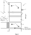
- Figure 1 shows a plan-view schematic of a bag-making production line comprising a web material feed station and a cutting section (16) and a bag forming/joining section (not shown).
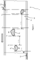
- a defects detection unit (4) comprising a light sensing unit (12) in the form of a sensor or a camera, an encoder, and a light emitting device (13) in the form of a backlight unit (refer to Figure 2 ) is mounted along the path of the traveling web material (1) in its web material feed/cutting section.
- the camera, the encoder, and the backlight unit are capable of communicating with a defects management control unit (5).
- a defects management control unit (5) processes the data received from the defects detection unit (4).
- Figure 5 shows the communication protocol between some of the various units of the defects management device (3). Upon detection of any defects (2) or irregularities in any area of the advancing web material (1), a signal is sent by the defect detection unit (4) to the control unit. The location of the defect (2) at the time of its detection is noted.
- the web material (1) As the web material (1) travels in the web material feed zone (14a) and if it is defect free, then the web material (1) gets cut into pieces for the purpose of product-making.
- the changing location of the defect (2) detected by the defects management device (3) on the advancing web material (1) is noted in the memory of the database (3a) of the defects management device (3), finally leading to identification of the piece of web material containing the defect, or defective cut pieces (1c).
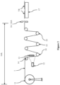
- rolls of final web material (1) or fabric are supplied to the conversion systems fitted with the web material defects management device (3) where a web material feed (1a) roller facilitates controlled entry of the web material (1) into the defects management device (3).
- Additional feed rollers facilitate movement of the web material (1) between various stations (not assigned numbers or shown) of the conversion line (6), such as an opening/folding station, a sealing station, of the conversion line.
- the provision of the defects detection unit (4) may be made between any two feed rollers depending on the requirement of the user.
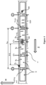
- Figure 3 shows a schematic of a web material (1) with a number of defects (2).
- the defects (2) within the main material (of width W M ) are denoted as D1, D2, D3, and so on.
- Defects (2) within the edge region are denoted as E0, E1, and so on.
- the defects (2) may be either from the main fabric or from the edge region.
- the feed roller (14) speed determines the speed of web material (1) advancing into the conversion line (6). This in turn determines the speed of the web material (1) travelling through the various parts of the conversion system. It is important to know the speed of web material (1) so that once the defective parts of web material (1) are detected and identified, the movement of the cutter that separates the defective sections (7) of web material from the defects-free sections (8) web material (1), can be controlled to make transverse cuts in the web material (1) at desired locations.
- the sensitivity or accuracy of the web defect management device (3) may be set to the individual customer requirement.
- a PLC logic of the conversion line control unit (15) diverts it onto a path leading to a rejects system located in rejects collection zone (10), where the defective cut pieces are rejected from the system.
- the device according to the invention has a completely separate cutting/feed unit which is controlled by a servo-drive unit and a bag forming/joining (sealing or seam making) unit. This enables one to drive the cutting/feed unit at a speed independent of that of the bag forming section.
- the defective pieces (1c) to be discarded or rejected are also called rejects.
- the rejects are ejected from the conversion line (6).
- the discharge system (not shown) for defective cut pieces may be a conveyor-belt-based system or one based on a clipper or using suitable pneumatic/suction system.
- the location of the discharge system may be upstream of the bag formation line.
- the activation of the discharge system is controlled on the basis of the error generated by web defect management device.
- the direction of travel of the web material (1) as it unrolls from the web material roll (1a) (defined as the longitudinal direction), and that of cut pieces immediately after the web material (1) is cut into pieces is substantially perpendicular to the direction of travel of web material (1) pieces in the bag manufacturing unit/line (defined as transverse direction).
- the defective cut pieces (1c) keep traveling in the original direction of the web material travel from the time of their being cut from the advancing web material (1) until they are collected in the rejects collection zone (10a).
- the normal/defects-free cut pieces (1b) enter the conversion line's downstream process flow or the production flow.
- a servo-driven roller facilitating a controlled actuation of the nip roller (not shown). This enables imparting motion to the defect-free web cut pieces (1b) along the transverse direction to facilitate their progress along the bag formation line while defective cut pieces are send to the rejects collection zone (10a).
- All automated systems to make bags or other products from cut pieces of web have a mechanism to 'pick up' cut pieces with the help of a nip roller.
- the actuation of the nip roller is controlled on the basis of an error signal generated by the web defect management device (3) indicating detection of a defect (2) in the web.
- the nip roller is controlled such that it does not 'pick up' the defective cut piece that is passing through the nip location.
- the nip roller is pressed down such that it grips the web material (1) cut piece that is traveling on a conveyor belt. If the nip roller doesn't get pressed down, the web cut piece doesn't get gripped and thus continues its travel into the rejects collection zone.
- the defective piece (1c) is taken out of the process flow.
- the frequency of the pieces being fed to the downstream process on the conversion line would change. This would possibly introduce undesirable irregularity in the conversion line processes depending on the number of defective sections (S D ) detected and separated.
- the speed of their feeding to the conversion line needs to vary depending on the number of defective pieces detected and separated.
- the defects (2) may include the following: holes, knots, breakages and overlaps, width (Wm) of web material (1) varying outside the accepted tolerance limit, structural defects in the edge zone (We).
- holes may be clubbed into clusters.
- Defects (2) may be point defects or defect-clusters - all termed as defects for the purpose of this disclosure.
- the actual identification of defects (2) using the defects detection unit (3) is carried out as follows.
- the defects detection unit (3) comprises a light emitting unit (13) and a light sensing unit (12), and a defects management control unit (5) that communicates with the light emitting unit (13) and the light sensing unit (12).
- the control unit (5) is also capable of communicating with the control unit (15) of the bag conversion line (6).
- the light emitting unit (13) emits light which passes through the travelling web material (1). The light that comes out of the travelling web material (1) is sensed by the light sensing unit (12).
- the web material is scanned through the combined steps of emitting and sensing of light, in other words, the term scanning in the sense of the present disclosure comprises the acts of emitting light and sensing the emitted light that passes through the web material (1).
- the light sensing unit (12) is capable of sensing the amount and uniformity of the intensity of light on the basis of which the defects identification unit (4) is able to make the determination of whether a defect actually exists.
- the light emitting unit (13) comprises at least two light emitters (13a). One that emits light of wavelengths suitable to detect defects within the width of main web material (Wm) and the other one that emits light of wavelengths suitable to detect the edge sections - that is the section that contains extension of the coating material. At any point in time, both light emitters are active. Depending on the nature of expected flaws to be detected, further lines of light emitters emitting light of intensity suitable for detecting specific types of flaws may be provided.
- the defect detection unit scans the entire width (W T ) of the web material (1) by an at least two-line scanning system - one line of light emitters for the defects in the main material and another line of lights for defects in the edge region.
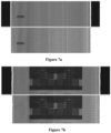
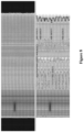
- Figures 7, 7A , 8 and 9 show, respectively, the images generated by the device of web material defect management showing defect-free and defective portions of web material.
- the light emitters (13a) may be in the form of a gas-based or a filament-based strip light emitting more or less continuous light and which are capable of emitting light over the entire width (Wm) of the main web material. Light emitters (13a) may also be made of discrete individual emitters that cover the entire width of the web material. It is important that emitted light reaches all parts of the web material (1) as the web material passes between the light emitting unit (13) and the light sensing unit (12).
- the web material (1) has mechanical and optical properties including opacity (termed as specified opacity) which depends on the raw material from which it is made.
- the light sensing unit (12) is activated depending on a predetermined speed of fabric feed rollers (14).
- the opacity varies within the acceptable range of the product specification. However, in the case a defect is present, the opacity of the material at the defect varies from the specified opacity of the material.
- the defects management device of the invention may be configured for individual web material properties so that the defects determination may be made during the scanning process.
- the light sensing unit/device (12) senses the light coming through web structure in form of small holes.
- the defect detection unit (3) evaluates the area of the set of holes and recognize it as normal or defective portion.
- the light passing through a defect-free portion (8) of a web material (1) is expected to be more or less uniform when it is detected by the sensing unit. Presence of defects (2) either creates opaqueness in the path of the travelling light or it reduces the opaqueness. It is by comparison of the sensed parameters of the received light with the expected values of the parameters that the presence of defects (2) is detected using the data and logic stored in the database (3a) of the defects management device (3).
- the tube type web material has at least two layers of material. Defects may be present on any or all layers.
- the defects management device detects defects on all layers. In reference to Figures 3 and 4 , if the web material (1) is in the form of a tube, the individual defects shown may be present on any of the layers of the material.
- defect detection unit One unique aspect of the defect detection unit is that entire width of the web material (1) is scanned in at one instance. However, in another aspect of the invention, scanning may be done in multiple instances or steps.
- the web material defects management device (3) of the invention is also capable of calculating the exact time and or location of the transverse cut that needs to be made in the web material to convert the web material into one or more pieces once a defective or indeed defect-free length is detected.
- One key object of the invention is to increase the productivity of the bag manufacturing line and minimise wastage. In the case of the web material that carries patterned printing (9), this aspect becomes particularly important.
- a cut in web material needs to be made by considering the defect location as well as the location of the next end of a printed pattern. If the bag is cut within a printed pattern, it will lead to waste of web material.
- the system of invention determines the end of defect or set of defects (see Figure 4 ) and also the location of the next end of printed pattern and ensures that the cut is made before the start of the next print pattern. In the case, there is no printed pattern, a cut is made after the last defect at a predetermined spacing.
- One aspect of the invention is that the movement of the cutter (16a) of the cutting station (16) is halted as soon as a first defect is detected.
- the cutter remains halted till the time a defect-free web material section has been identified and the location of the web material where the next cut needs to be made arrives in the cutting vicinity of the cutter (16a).
- the cutting vicinity is a predetermined first distance from the cutter which may depend on the processing speed of the bag making line, the web material type, and other parameters that a person skilled in the art may consider important.
- the coated material extends laterally beyond the edge of the uncoated or the main web material.
- the total width (W T ) of the coated web material is the distance between the edges of the coated web material.
- the defects in the edge region, where only the coating material exists, tend to be of different type than those in the main web material.
- the main web material comprises woven tapes, where the tapes are made typically from opaque or semi-opaque materials, whereas the coating material is much more transparent.
- Another difference arises from the fact that the coating is applied to the coated web material from a process that is entirely different from the process of making the woven web material from tapes.
- the light radiation suitable for efficient detection of defects in the edge region and those in the main web material may be different but will be known to a person skilled in the art.
- the system of invention provides separate light emission emitters (13a) within the light emitting device (13) for the edge region and the main web material.
- the defects (2), once identified and detected by the device (3) are also displayed on a monitor (not shown).
- the length of defect-free web material required to make a single bag of predetermined dimensions is termed as the predetermined web material bag piece length L.
- Defects (2) in a web material (1) may be located anywhere along the web material - they may be in the edge region (1e) where coating of the web material extends, or in the main material (1d) region (see Figure 6 ).
- the system or device (3) of invention is capable of registering the defects locations along the running web material and determining when a web material section (S DF ) suitable to make a defect-free cut piece is available.
- the system of invention is capable of determining the defective section(s) (S D ) of web material that should be removed from the production flow on the conversion line (6).
- the defect management device (3) registers it. It may assign it an identification number.
- the defects management device (3) has a co-ordinate frame of reference to determine planar co-ordinates of all points on the advancing web material (1) and also the time of registration of defects.
- the defects management device (3) may include the database (3a) information on identified/registered defect identification number, respective co-ordinates, and time of detection/registration.
- bags may be made from flat web material or tube type web material. If the starting material is a flat web material, it is converted into a continuous tube material. At some point during the process on the bag conversion line (1), tubes are cut into pieces of predetermined lengths, say L, depending on the bag size. Length L is such that it has sufficient margin for folding and stitching/sealing such that when a bag is made from the piece of length L, it is of the specified dimensions. It is important that entire length L of the piece, measured in the direction of advancement of web material, should be defect-free. As the location and number of defects cannot be controlled, it is important that the web material defects management device identifies defective web material portions that are at least of length L, and preferably integer multiples of L.
- Advancing web material (1) may contain a number of defects located randomly (see Figure 3 ). Any time - after the start of the defect identification process on a web material - a defect is determined, the defect management device registers it in its database as a first defect (D1). When the very next defect is identified, the system acknowledges it as the second defect (D2) and registers it in its database. All defects have finite dimensions. As an example, the positions of two defects along the travelling web material are identified as P1 and P2 in reference to the direction of travel of the web material. The clear length of the web material between the defects at the two positions P1 and P2 is denoted as l. The time of identification of the two defects is denoted as T1 and T2.
- the web monitoring system calculates the clear length l (in the direction of travel of web material) between the first and the second defects. If l is greater than or equal to L, the monitoring system recognises the section of the web material between the first and second defects as defect-free and registers it as suitable for making a bag. The very first instance of the occurrence of a defect-free length L is registered as the first defect-free length. Once the first defect-free length of the web material advances past the defects detection unit (4), it will, at some point in time, arrive at the cutting station (16) where the web material will be cut transversely to make a web material piece of length L. The locations where cuts would be made in an optimal situation are denoted as Co, C 1 , C 2 , C 3 in Figure 4 .
- Defects in the end region are denoted as En (n stands for n th defect).
- Figure 3 shows E 0 and E 4 .
- any defects - those from the end region as well as those from the main web material are considered.
- the second defect (D2) is reassigned as a first defect (D1).
- the next consecutive defect is acknowledged as a second defect (D2) and its planar co-ordinates and time of identification recorded.
- the defects management device (3) once again determines the length l between the new consecutive pair of defects (2) and determines if there exists length L between the two. If l is equal to or greater than L, then the defects management device (3) once again marks the section of the web material as defect-free and suitable for cutting for bag making purpose.
- the defects management device determines that the section between the defects D1 and D2 is not suitable for bag making purpose, that is to say it's a defective section (S D ) suitable for removing from the process flow of the bag conversion line (6).
- the defects management device (3) thus continues to look for the next section of defect-free web material of length L.
- the web material may come in two categories:
- locations of cuts are the ends of the section defined as having the defect-free length L.
- the time of their passage in front of the light emitting device (13) is noted.
- the expected time of arrival of the two ends of the defect-free length L at the cutting station (16) is calculated.
- the cutter (16a) is made operative to make a cut at both ends of the defect-free section.
- the defects management device (3) calculates the length L D of the defective web material - that is the web material between the trailing end of a defect-free section and the front end of the next consecutive defect-free section of length L.
- L D is greater than L, it means that the stretch L D carries equivalent of multiple pieces of bag lengths. However, since the entire stretch L D is defective, there do not need to be made intermediate cuts at length L, but only one cut needs to be made at the trailing end of the stretch of length L D .
- the defects management device (3) upon determination that L D is greater than L, send a signal to the controller of the conversion unit to make the cutter inoperative until such time that that the trailing end of the defective piece of length L D arrives at the cutting station (16).
- the length l suitable for cutting out a defective piece (1c) may be any length including a length less than L.
- the defects management device (3) In the case of a web material carrying a printed pattern of length L P , the defects management device (3) has to find not only a defect-free web material section of length L D which is at least equal to L, but it also needs check whether it coincides with the print pattern. If there is a mismatch between the two, i.e. the web material section of length L and the print pattern do not coincide, the defects management device (3) allows defect-free web material to be identified as defective until the point where L D equals some integer multiple of L. This is illustrated in Figure 4 where from the time the cut C1 is made, the system further encounters defects D1, D2, and D3, and determines the locations of cuts C2 and C3. The decision to make a cut at C2 is made only once the position C3 has passed under the light emitting device (13).
- the operator of the defects management device (3) may choose not to make the cutting tool inoperative at locations such as C' 1 , C" 1 .
- the defects management device (3) is capable of adjusting the calculation of travel time accordingly.
- the defects management device (3) is also capable of determining the length of web material within which not a single continuous defect-free portion of length L exists.
- the defects management device (3) allows such portions to pass through the web cutter station by making the cutter (16a) inoperative and thereby without making any cut.
- the cut locations are dependent only on the locations of defects.
- FIGS 7A, 7B , 8 , and 9 Examples of web materials as scanned by the device of defect management are seen from Figures 7A, 7B , 8 , and 9 .
- the images are produced by a two-line system of scanning herein one light emitter is used to produce the image of the main web material and another light emitter is used to produce the image of the edge region.
- Figures 7A and 7B show the computer images of the defect-free portions of web material as scanned by the device of invention for both web material with printed pattern and without it.. No defects are identified by the device of invention, as none exists
- Figures 8 shows the computer images of the defective portions of web material as scanned by the device of invention for web material without print pattern. As seen in the upper half of the image, the device of invention has detected defects in the edge region. As also seen in the lower half of the image, the device of invention has detected defects in the main web material.
- Figures 9 shows the computer images of the defective portions of web material as scanned by the device of invention for web material with print pattern. As seen in the upper half of the image, the device of invention has detected defects in the edge region. As also seen in the lower half of the image, the device of invention has detected defect in the main web material.
Landscapes
- Investigating Materials By The Use Of Optical Means Adapted For Particular Applications (AREA)
- Making Paper Articles (AREA)
- Treatment Of Fiber Materials (AREA)
- Controlling Rewinding, Feeding, Winding, Or Abnormalities Of Webs (AREA)
- General Factory Administration (AREA)
Claims (15)
- Vorrichtung zur Handhabung von Fehlern (2) in einem sich vorwärts bewegenden Bahnmaterial (1), das an einer Umwandlungslinie (6) vorgesehen ist, wobei die Umwandlungslinie (6) Verarbeitungsstationen zum Herstellen von Beuteln aus dem Bahnmaterial (1) aufweist, wobei die Verarbeitungsstationen Vorschneide-Verarbeitungsstationen, eine Schneidestation (16) und Nachschneide-Verarbeitungsstationen sowie eine Anzahl von Zufuhrwalzen (14) aufweisen, welche die Bewegung des Bahnmaterials (1) zwischen zwei beliebigen Stationen erleichtern,dadurch gekennzeichnet, dass die Vorrichtung eine Fehlererkennungseinheit (4) und eine Fehlermanagement-Steuereinheit (5) aufweist,wobei die Fehlererkennungseinheit (4) in der Lage ist zum:- Erkennen von Fehlern an einer sich vorwärts bewegenden Bahn, Bestimmen von Positionen von Schnitten, die an dem Bahnmaterial (1) vorgenommen werden sollen,- Kommunizieren mit der Fehlermanagement-Steuereinheit (5), um eine Datenbank von Fehlern (2), deren Positionen zum Zeitpunkt der Erkennung zu führen, und Überwachen des Fortschreitens von Fehlern entlang des sich vorwärts bewegenden Bahnmaterials (1);wobei die Fehlermanagement-Steuereinheit (5) in der Lage ist zum:- Kommunizieren mit einer Umwandlungslinien-Steuereinheit (15), um den Schneidevorgang der Schneidestation (16) und alle Vorschneidevorgänge der Umwandlungslinie (6) zu steuern, um Stücke aus fehlerhaftem (1c) und fehlerfreiem Bahnmaterial (1b) herzustellen, und- Steuern des Trennprozesses der fehlerhaften Stücke (1c) des Bahnmaterials (1) von dem stromabwärtigen Prozessfluss der Umwandlungslinie (6), ohne das sich vorwärts bewegende Bahnmaterial (1) zu stoppen.
- Vorrichtung nach Anspruch 1, wobei die Fehlererkennungseinheit (4) eine lichtemittierende Einheit (13), um Licht auf das Bahnmaterial (1) zu emittieren, eine Lichtsensoreinheit (12) zum Sensieren des emittierten Lichts, das aus dem Bahnmaterial (1) kommt, sowie eine Erkennungssteuereinheit aufweist, wobei die Lichtemissionseinheit (13) zumindest zwei Lichtemitter aufweist, die Licht emittieren, das durch das sich vorwärts bewegende Bahnmaterial (1) hindurchtritt, die Lichtsensoreinheit (12) in der Lage ist, Licht zu sensieren, das durch das sich vorwärts bewegende Bahnmaterial (1) hindurchtritt, oder das Bahnmaterial (1) abzutasten, und das Vorhandensein eines Fehlers zu bestimmen.
- Vorrichtung nach Anspruch 2, wobei das Bestimmen des Vorhandenseins eines Fehlers (2) erfolgt, wenn bestimmt wird, dass die auf Grundlage des Volumens und der Intensität von detektiertem Licht berechnete Schwankung der Opazität des Bahnmaterials (1) von einer vorgegebenen Opazität des Bahnmaterials (1) abweicht.
- Vorrichtung nach einem der Ansprüche 1 bis 3, wobei die Lichtemissionseinheit (13) Lichtemitter aufweist, die gasbasierte oder fadenbasierte Streifenlichter sind, die in der Lage sind, Licht über die gesamte Breite des Bahnmaterials (1) zu emittieren, oder diskrete einzelne Lichtemitter aufweist, welche die gesamte Breite des Bahnmaterials (1) abdecken, wobei die Lichtemissionseinheit (13) bevorzugte weitere Linien von Lichtemittern aufweist, die Licht mit einer Intensität emittieren, die zum Erkennen von bestimmten Arten von Mängeln geeignet ist.
- Vorrichtung nach einem der Ansprüche 2 bis 3, wobei das Abtasten des Bahnmaterials (1) auf einmal erfolgt.
- Vorrichtung nach einem der Ansprüche 1 bis 5, wobei die Fehlermanagement-Steuereinheit (5) in der Lage ist, die Zeit und/oder die Position des Querschnitts zu berechnen, der in dem Bahnmaterial (1) vorgenommen werden muss, um das Material in ein fehlerhaftes Stück (1c) oder ein fehlerfreies Stück (1b) umzuwandeln, und wobei die Fehlererkennungseinheit (4) bevorzugt zwischen zwei beliebigen aufeinanderfolgenden Zufuhrwalzen platziert ist.
- Vorrichtung nach einem der Ansprüche 1 bis 6, wobei das Bahnmaterial (1) glatt oder mit gemustertem Design (9) oder mit nicht gemustertem Design bedruckt ist.
- Vorrichtung nach einem der Ansprüche 1 bis 7, wobei nach Erkennen eines Fehlers (2) die Fehlermanagement-Steuereinheit (5) die Umwandlungslinien-Steuereinheit (15) anweist, die Schneidestation (16) der Umwandlungslinie (6) bis zu einer weiteren Anweisung außer Betrieb zu setzen.
- Vorrichtung nach den Ansprüchen 1 bis 8, wobei in dem Fall, dass das Bahnmaterial (1) einen gemusterten Druck (9) trägt, die Fehlermanagement-Steuereinheit (5) sicherstellt, dass die Schneidestation (16) keinen Schnitt innerhalb der Druckzone ausführt.
- Vorrichtung nach den Ansprüchen 1 bis 8, wobei im Fall eines glatten Bahnmaterials (1) oder des Bahnmaterials (1) mit nicht-gemustertem Druck die Fehlermanagement-Steuereinheit (5) eine lichte Länge l zwischen beliebigen zwei aufeinanderfolgenden Fehlern (l) berechnet, und falls l größer oder gleich der zur Herstellung eines Beutels erforderlichen Länge L des Bahnmaterials (1) ist, es den Abschnitt des Bahnmaterials (1) zwischen den beiden Fehlern (2) als fehlerfrei registriert und die Steuereinheit der Umwandlungslinie (15) benachrichtigt, die Schneideeinheit (16) zu betreiben, um ein fehlerfreies Stück (1b) herzustellen.
- Vorrichtung nach den Ansprüchen 1 bis 8, wobei im Falle eines glatten Bahnmaterials (1) die Fehlermanagement-Steuereinheit (5) die lichte Länge l zwischen zwei beliebigen aufeinanderfolgenden Fehlern berechnet und, falls l kleiner als die Länge L an Bahnmaterial ist, die benötigt wird, um einen Beutel herzustellen, die Fehlermanagement-Steuereinheit (5) damit fortfährt, das Bahnmaterial (1) abzutasten, bis ein Paar aufeinanderfolgender Fehler erkannt wird, deren lichte Länge größer als L ist, und diesen Abschnitt des Bahnmaterials (1) als einen weiteren fehlerfreien Abschnitt registriert, woraufhin sie die Steuereinheit der Umwandlungslinie (15) benachrichtigt, die Schneidestation (16) zu betreiben, um ein fehlerfreies Stück (1b) herzustellen.
- Vorrichtung nach einem der Ansprüche 10 bis 11, wobei, falls zwischen den zwei aufeinanderfolgenden fehlerfreien Abschnitten von Bahnmaterial (8) ein Abschnitt fehlerhaften Bahnmaterials (7) mit einer Länge größer als L existiert, die Fehlermanagement-Steuereinheit ( 5) die Umwandlungslinien-Steuereinheit (15) anweist, einen einzelnen Schnitt an dem hinteren Ende des Abschnitts fehlerhaften Bahnmaterials (7) und keine Schnitte dazwischen vorzunehmen.
- Vorrichtung nach den Ansprüchen 1 bis 12, wobei die Nachschneidegeschwindigkeit der fehlerfreien Stücke (1b), die der Umwandlungslinie (6) nach dem Schneidevorgang zugeführt werden, auf Grundlage der Anzahl von Fehlern (2) und deren Verteilung entlang der Länge des sich vorwärts bewegenden Bahnmaterials (1) gesteuert wird, wobei die Nachschneidegeschwindigkeit bevorzugt variabel ist und innerhalb eines vorbestimmten Bereichs gehalten wird.
- Vorrichtung nach einem der Ansprüche 1 bis 13, wobei, sobald ein Fehler (2) erkannt wird, falls Vorschneidevorgänge wie Bahnperforation oder Lochherstellung vorhanden sind, dann diese Vorgänge bei Erkennen eines fehlerhaften Abschnitts in der Bahn deaktiviert werden.
- Verfahren zum Handhaben von Fehlern in einem sich vorwärts bewegenden Bahnmaterial (1), das an einer Umwandlungslinie (6) vorgesehen ist, wobei die Umwandlungslinie (6) Verarbeitungsstationen zum Herstellen von Beuteln aus dem Bahnmaterial (1) aufweist, wobei die Verarbeitungsstationen Vorschneide-Verarbeitungsstationen, eine Schneidestation (16) und Nachschneide-Verarbeitungsstationen sowie eine Anzahl von Zufuhrwalzen aufweist, welche die Bewegung des Bahnmaterials (1) zwischen zwei Stationen erleichtern, dadurch gekennzeichnet, dass das Verfahren umfasst:- Bereitstellen einer Vorrichtung zum Handhaben von Fehlern in sich vorwärts bewegendem Bahnmaterial (1);- ohne Stoppen des sich vorwärts bewegenden Bahnmaterials (1):a. Detektieren von Fehlern (2) an einer sich vorwärts bewegenden Bahn, Bestimmen von Positionen von Schnitten, die an dem Bahnmaterial (1) vorzunehmen sind,b. Kommunizieren mit einer Fehlermanagement-Steuereinheit (5) der Vorrichtung, um eine Datenbank von Fehlern (2), deren Positionen zum Zeitpunkt des Erkennens zu führen, und Überwachen des Fortschreitens von Fehlern (2) entlang des sich vorwärts bewegenden Bahnmaterials (1);c. Kommunizieren mit einer Umwandlungslinien-Steuereinheit (15), um den Schneidevorgang und die Vorschneidevorgänge der Schneidestation (16) der Umwandlungslinie (6) zu steuern, um Stücke aus fehlerhaftem und fehlerfreiem Bahnmaterial (1c und 1b) herzustellen, undd. Steuern des Trennprozesses der fehlerhaften Stücke von Bahnmaterial (7) von dem stromabwärtigen Prozessfluss der Umwandlungslinie (6);e. Senden von fehlerfreien Stücken (1b) an stromabwärtige Verarbeitungsstationen (6a).
Applications Claiming Priority (2)
| Application Number | Priority Date | Filing Date | Title |
|---|---|---|---|
| IN201811020878 | 2018-07-08 | ||
| PCT/IB2019/055747 WO2020012311A2 (en) | 2018-07-08 | 2019-07-05 | Device and method for managing defects in a web material on conversion lines |
Publications (2)
| Publication Number | Publication Date |
|---|---|
| EP3678858A2 EP3678858A2 (de) | 2020-07-15 |
| EP3678858B1 true EP3678858B1 (de) | 2023-05-24 |
Family
ID=67957186
Family Applications (1)
| Application Number | Title | Priority Date | Filing Date |
|---|---|---|---|
| EP19769214.8A Active EP3678858B1 (de) | 2018-07-08 | 2019-07-05 | Verfahren und vorrichtung zur handhabung von fehlern in einer warenbahn einer verarbeitungsanlage |
Country Status (5)
| Country | Link |
|---|---|
| EP (1) | EP3678858B1 (de) |
| CN (1) | CN111788066B (de) |
| RU (1) | RU2757557C1 (de) |
| TW (1) | TWI716027B (de) |
| WO (1) | WO2020012311A2 (de) |
Families Citing this family (5)
| Publication number | Priority date | Publication date | Assignee | Title |
|---|---|---|---|---|
| WO2021152442A1 (en) * | 2020-01-29 | 2021-08-05 | Lohia Corp Limited | A semi-automated device and a method for cutting advancing web material |
| CN112590390A (zh) * | 2020-12-15 | 2021-04-02 | 广东新宏泽包装股份有限公司 | 一种凹印机在线质量检测设备及检测方法 |
| CN113145489B (zh) * | 2021-04-28 | 2022-05-20 | 凌云光技术股份有限公司 | 一种制袋过程中对缺陷产品进行剔除的系统、方法及设备 |
| CN113808108B (zh) * | 2021-09-17 | 2023-08-01 | 太仓中科信息技术研究院 | 一种印刷膜缺陷视觉检测方法和系统 |
| CN119164879B (zh) * | 2024-08-30 | 2026-02-06 | 浙江玻尔智造科技有限公司 | 一种多站点aoi资料关联缺陷检测方法及检测系统 |
Family Cites Families (21)
| Publication number | Priority date | Publication date | Assignee | Title |
|---|---|---|---|---|
| GB1010154A (en) * | 1963-03-12 | 1965-11-17 | Leonard Thomas Frank Bryan | Improvements in or relating to devices for detecting flaws in fabrics |
| SU734016A2 (ru) * | 1978-02-20 | 1980-05-15 | Научно-Производственное Объединение "Вымпел" Управления Местной Промышленности Исполкома Ленгорсовета | Устройство дл резки ленточного упаковочного материала на заготовки |
| CH660920A5 (de) | 1983-02-03 | 1987-05-29 | Zellweger Uster Ag | Verfahren und vorrichtung zur automatischen erkennung von fehlern in geweben und aehnlichen textilen flaechengebilden. |
| DE4312452A1 (de) | 1993-04-16 | 1994-10-20 | Erhardt & Leimer Gmbh | Verfahren zur berührungslosen optischen Messung von qualitätsbestimmenden Parametern textiler Oberflächen sowie Anordnung zur Durchführung des Verfahrens |
| RU32032U1 (ru) * | 2003-06-04 | 2003-09-10 | Общество с ограниченной ответственностью Научно-производственное предприятие "АВА" | Линия для изготовления заготовок многослойных бумажных мешков |
| JP2005114624A (ja) * | 2003-10-09 | 2005-04-28 | Nitto Denko Corp | シート状製品の検査方法及びシート状製品の検査システム及びシート状製品及び枚葉物 |
| RU40251U1 (ru) * | 2004-03-04 | 2004-09-10 | ООО фирма "НИТЕП" | Станок для продольной резки рулонных материалов |
| CN1930467A (zh) | 2004-03-05 | 2007-03-14 | 乌斯特技术股份公司 | 用于监控运动的物品轨道的装置 |
| JP4707632B2 (ja) * | 2005-09-21 | 2011-06-22 | 旭化成エンジニアリング株式会社 | 欠陥検査装置 |
| AU2005337594B2 (en) * | 2005-10-19 | 2010-06-17 | Orihiro Engineering Co., Ltd. | Film feeding device and packaging device with the same |
| DE102008017441B4 (de) * | 2008-04-03 | 2014-05-28 | Windmöller & Hölscher Kg | Verfahren und Anordnung zur Herstellung von Säcken aus Gewebematerial |
| AT508159B1 (de) | 2009-06-05 | 2010-11-15 | Starlinger & Co Gmbh | Fehlerstellenerkennung |
| CN203173571U (zh) * | 2013-04-16 | 2013-09-04 | 云南恩典科技产业发展有限公司 | 烟用接装纸复卷机 |
| CN106796184B (zh) * | 2014-10-10 | 2019-11-19 | 住友化学株式会社 | 隔膜及隔膜卷料的制造方法、隔膜卷料及其制造装置 |
| CZ306557B6 (cs) * | 2015-07-10 | 2017-03-08 | Pegas Nonwovens S.R.O. | Způsob detekce vad v pohybujícím se pásu poddajného vlákenného materiálu |
| CN105181655B (zh) * | 2015-10-16 | 2018-08-03 | 歌尔股份有限公司 | 用于透光率检测装置的光源模组及透光率检测装置 |
| CN105301008A (zh) * | 2015-11-24 | 2016-02-03 | 云南恩典科技产业发展有限公司 | 一种接装纸质量检测警示系统及质量在线检测方法 |
| CN105510333B (zh) * | 2015-12-16 | 2018-09-18 | 凌云光技术集团有限责任公司 | 一种塑料薄膜软包装印品中缺陷的定位方法及装置 |
| CN205633256U (zh) * | 2016-01-11 | 2016-10-12 | 深圳市麦克斯泰有限公司 | 自动化验布机 |
| KR101674353B1 (ko) * | 2016-05-30 | 2016-11-08 | 주식회사 엘지화학 | 디스플레이 유닛의 연속 제조방법 및 장치 |
| JP2018047655A (ja) * | 2016-09-23 | 2018-03-29 | 三菱重工機械システム株式会社 | シートの不良除去装置及び方法、シートの不良除去制御装置、段ボールシートの製造装置 |
-
2019
- 2019-07-05 CN CN201980015464.0A patent/CN111788066B/zh active Active
- 2019-07-05 WO PCT/IB2019/055747 patent/WO2020012311A2/en not_active Ceased
- 2019-07-05 EP EP19769214.8A patent/EP3678858B1/de active Active
- 2019-07-05 RU RU2020116861A patent/RU2757557C1/ru active
- 2019-07-08 TW TW108124008A patent/TWI716027B/zh active
Also Published As
| Publication number | Publication date |
|---|---|
| RU2757557C1 (ru) | 2021-10-18 |
| TWI716027B (zh) | 2021-01-11 |
| EP3678858A2 (de) | 2020-07-15 |
| CN111788066B (zh) | 2022-08-26 |
| CN111788066A (zh) | 2020-10-16 |
| BR112020022725A2 (pt) | 2021-02-02 |
| WO2020012311A2 (en) | 2020-01-16 |
| TW202006348A (zh) | 2020-02-01 |
| WO2020012311A3 (en) | 2020-04-02 |
Similar Documents
| Publication | Publication Date | Title |
|---|---|---|
| EP3678858B1 (de) | Verfahren und vorrichtung zur handhabung von fehlern in einer warenbahn einer verarbeitungsanlage | |
| JP3216622U (ja) | 製品を制御又は管理するためのユニット | |
| RU2532157C2 (ru) | Устройство и способ обнаружения дефектных мест в тканях и маркировка | |
| US9387131B2 (en) | Apparatus and method for minimizing waste and improving quality and production in web processing operations by automated threading and re-threading of web materials | |
| JP6653307B2 (ja) | 製品の製造方法及び製品の製造装置 | |
| CA2637549C (en) | Apparatus and method for minimizing waste and improving quality and production in web processing operations | |
| JP5479998B2 (ja) | ブランキングラインにおける表面不良ブランクの識別装置 | |
| JP5936870B2 (ja) | 物品検査システム | |
| CN107850553A (zh) | 检测柔性纤维材料移动片材的缺陷的方法 | |
| TWI766566B (zh) | 半自動化裝置和用於切割前進網材料的方法 | |
| JP6113190B2 (ja) | 清掃部材を製造する方法及びシステム | |
| CN105839381A (zh) | 用于由织物材料制造袋子的方法 | |
| WO2024231880A1 (en) | A deformity detection system and a method for detecting fabric deformities and management thereof | |
| US11981520B2 (en) | Apparatus and method for web twist defect correction | |
| CN110589122A (zh) | 检查装置、ptp包装机和ptp片的制造方法 | |
| BR112020022725B1 (pt) | Dispositivo e método para gestão de defeitos em um material de tecido em linhas de conversão | |
| US20100255973A1 (en) | Method of making and inspecting bags | |
| TR2021016828T (tr) | İlerleyen ağ malzemesinin kesilmesi için bir yarı otomatik cihaz ve bir yöntem. | |
| CN211196732U (zh) | 烟包封签检测装置 | |
| JP2004115113A (ja) | 充填包装方法および充填包装装置 | |
| JPS6183023A (ja) | ダイヤフラム製造における基布不良部位の検知方法 | |
| JPH0720797B2 (ja) | 枚葉シート選別装置 |
Legal Events
| Date | Code | Title | Description |
|---|---|---|---|
| STAA | Information on the status of an ep patent application or granted ep patent |
Free format text: STATUS: UNKNOWN |
|
| STAA | Information on the status of an ep patent application or granted ep patent |
Free format text: STATUS: THE INTERNATIONAL PUBLICATION HAS BEEN MADE |
|
| PUAI | Public reference made under article 153(3) epc to a published international application that has entered the european phase |
Free format text: ORIGINAL CODE: 0009012 |
|
| STAA | Information on the status of an ep patent application or granted ep patent |
Free format text: STATUS: REQUEST FOR EXAMINATION WAS MADE |
|
| 17P | Request for examination filed |
Effective date: 20200409 |
|
| AK | Designated contracting states |
Kind code of ref document: A2 Designated state(s): AL AT BE BG CH CY CZ DE DK EE ES FI FR GB GR HR HU IE IS IT LI LT LU LV MC MK MT NL NO PL PT RO RS SE SI SK SM TR |
|
| AX | Request for extension of the european patent |
Extension state: BA ME |
|
| DAV | Request for validation of the european patent (deleted) | ||
| DAX | Request for extension of the european patent (deleted) | ||
| GRAP | Despatch of communication of intention to grant a patent |
Free format text: ORIGINAL CODE: EPIDOSNIGR1 |
|
| STAA | Information on the status of an ep patent application or granted ep patent |
Free format text: STATUS: GRANT OF PATENT IS INTENDED |
|
| RAP3 | Party data changed (applicant data changed or rights of an application transferred) |
Owner name: LOHIA CORP LIMITED |
|
| INTG | Intention to grant announced |
Effective date: 20230120 |
|
| GRAS | Grant fee paid |
Free format text: ORIGINAL CODE: EPIDOSNIGR3 |
|
| GRAA | (expected) grant |
Free format text: ORIGINAL CODE: 0009210 |
|
| STAA | Information on the status of an ep patent application or granted ep patent |
Free format text: STATUS: THE PATENT HAS BEEN GRANTED |
|
| AK | Designated contracting states |
Kind code of ref document: B1 Designated state(s): AL AT BE BG CH CY CZ DE DK EE ES FI FR GB GR HR HU IE IS IT LI LT LU LV MC MK MT NL NO PL PT RO RS SE SI SK SM TR |
|
| REG | Reference to a national code |
Ref country code: GB Ref legal event code: FG4D |
|
| REG | Reference to a national code |
Ref country code: CH Ref legal event code: EP |
|
| REG | Reference to a national code |
Ref country code: DE Ref legal event code: R096 Ref document number: 602019029292 Country of ref document: DE |
|
| REG | Reference to a national code |
Ref country code: AT Ref legal event code: REF Ref document number: 1569282 Country of ref document: AT Kind code of ref document: T Effective date: 20230615 |
|
| REG | Reference to a national code |
Ref country code: IE Ref legal event code: FG4D |
|
| REG | Reference to a national code |
Ref country code: LT Ref legal event code: MG9D |
|
| REG | Reference to a national code |
Ref country code: NL Ref legal event code: MP Effective date: 20230524 |
|
| PG25 | Lapsed in a contracting state [announced via postgrant information from national office to epo] |
Ref country code: SE Free format text: LAPSE BECAUSE OF FAILURE TO SUBMIT A TRANSLATION OF THE DESCRIPTION OR TO PAY THE FEE WITHIN THE PRESCRIBED TIME-LIMIT Effective date: 20230524 Ref country code: PT Free format text: LAPSE BECAUSE OF FAILURE TO SUBMIT A TRANSLATION OF THE DESCRIPTION OR TO PAY THE FEE WITHIN THE PRESCRIBED TIME-LIMIT Effective date: 20230925 Ref country code: NO Free format text: LAPSE BECAUSE OF FAILURE TO SUBMIT A TRANSLATION OF THE DESCRIPTION OR TO PAY THE FEE WITHIN THE PRESCRIBED TIME-LIMIT Effective date: 20230824 Ref country code: NL Free format text: LAPSE BECAUSE OF FAILURE TO SUBMIT A TRANSLATION OF THE DESCRIPTION OR TO PAY THE FEE WITHIN THE PRESCRIBED TIME-LIMIT Effective date: 20230524 Ref country code: ES Free format text: LAPSE BECAUSE OF FAILURE TO SUBMIT A TRANSLATION OF THE DESCRIPTION OR TO PAY THE FEE WITHIN THE PRESCRIBED TIME-LIMIT Effective date: 20230524 |
|
| PG25 | Lapsed in a contracting state [announced via postgrant information from national office to epo] |
Ref country code: RS Free format text: LAPSE BECAUSE OF FAILURE TO SUBMIT A TRANSLATION OF THE DESCRIPTION OR TO PAY THE FEE WITHIN THE PRESCRIBED TIME-LIMIT Effective date: 20230524 Ref country code: PL Free format text: LAPSE BECAUSE OF FAILURE TO SUBMIT A TRANSLATION OF THE DESCRIPTION OR TO PAY THE FEE WITHIN THE PRESCRIBED TIME-LIMIT Effective date: 20230524 Ref country code: LV Free format text: LAPSE BECAUSE OF FAILURE TO SUBMIT A TRANSLATION OF THE DESCRIPTION OR TO PAY THE FEE WITHIN THE PRESCRIBED TIME-LIMIT Effective date: 20230524 Ref country code: LT Free format text: LAPSE BECAUSE OF FAILURE TO SUBMIT A TRANSLATION OF THE DESCRIPTION OR TO PAY THE FEE WITHIN THE PRESCRIBED TIME-LIMIT Effective date: 20230524 Ref country code: IS Free format text: LAPSE BECAUSE OF FAILURE TO SUBMIT A TRANSLATION OF THE DESCRIPTION OR TO PAY THE FEE WITHIN THE PRESCRIBED TIME-LIMIT Effective date: 20230924 Ref country code: HR Free format text: LAPSE BECAUSE OF FAILURE TO SUBMIT A TRANSLATION OF THE DESCRIPTION OR TO PAY THE FEE WITHIN THE PRESCRIBED TIME-LIMIT Effective date: 20230524 Ref country code: GR Free format text: LAPSE BECAUSE OF FAILURE TO SUBMIT A TRANSLATION OF THE DESCRIPTION OR TO PAY THE FEE WITHIN THE PRESCRIBED TIME-LIMIT Effective date: 20230825 |
|
| PG25 | Lapsed in a contracting state [announced via postgrant information from national office to epo] |
Ref country code: FI Free format text: LAPSE BECAUSE OF FAILURE TO SUBMIT A TRANSLATION OF THE DESCRIPTION OR TO PAY THE FEE WITHIN THE PRESCRIBED TIME-LIMIT Effective date: 20230524 |
|
| PG25 | Lapsed in a contracting state [announced via postgrant information from national office to epo] |
Ref country code: SK Free format text: LAPSE BECAUSE OF FAILURE TO SUBMIT A TRANSLATION OF THE DESCRIPTION OR TO PAY THE FEE WITHIN THE PRESCRIBED TIME-LIMIT Effective date: 20230524 |
|
| PG25 | Lapsed in a contracting state [announced via postgrant information from national office to epo] |
Ref country code: SM Free format text: LAPSE BECAUSE OF FAILURE TO SUBMIT A TRANSLATION OF THE DESCRIPTION OR TO PAY THE FEE WITHIN THE PRESCRIBED TIME-LIMIT Effective date: 20230524 Ref country code: SK Free format text: LAPSE BECAUSE OF FAILURE TO SUBMIT A TRANSLATION OF THE DESCRIPTION OR TO PAY THE FEE WITHIN THE PRESCRIBED TIME-LIMIT Effective date: 20230524 Ref country code: RO Free format text: LAPSE BECAUSE OF FAILURE TO SUBMIT A TRANSLATION OF THE DESCRIPTION OR TO PAY THE FEE WITHIN THE PRESCRIBED TIME-LIMIT Effective date: 20230524 Ref country code: EE Free format text: LAPSE BECAUSE OF FAILURE TO SUBMIT A TRANSLATION OF THE DESCRIPTION OR TO PAY THE FEE WITHIN THE PRESCRIBED TIME-LIMIT Effective date: 20230524 Ref country code: DK Free format text: LAPSE BECAUSE OF FAILURE TO SUBMIT A TRANSLATION OF THE DESCRIPTION OR TO PAY THE FEE WITHIN THE PRESCRIBED TIME-LIMIT Effective date: 20230524 |
|
| REG | Reference to a national code |
Ref country code: DE Ref legal event code: R097 Ref document number: 602019029292 Country of ref document: DE |
|
| PG25 | Lapsed in a contracting state [announced via postgrant information from national office to epo] |
Ref country code: MC Free format text: LAPSE BECAUSE OF FAILURE TO SUBMIT A TRANSLATION OF THE DESCRIPTION OR TO PAY THE FEE WITHIN THE PRESCRIBED TIME-LIMIT Effective date: 20230524 |
|
| PG25 | Lapsed in a contracting state [announced via postgrant information from national office to epo] |
Ref country code: MC Free format text: LAPSE BECAUSE OF FAILURE TO SUBMIT A TRANSLATION OF THE DESCRIPTION OR TO PAY THE FEE WITHIN THE PRESCRIBED TIME-LIMIT Effective date: 20230524 |
|
| REG | Reference to a national code |
Ref country code: CH Ref legal event code: PL |
|
| REG | Reference to a national code |
Ref country code: BE Ref legal event code: MM Effective date: 20230731 |
|
| PG25 | Lapsed in a contracting state [announced via postgrant information from national office to epo] |
Ref country code: LU Free format text: LAPSE BECAUSE OF NON-PAYMENT OF DUE FEES Effective date: 20230705 |
|
| PG25 | Lapsed in a contracting state [announced via postgrant information from national office to epo] |
Ref country code: LU Free format text: LAPSE BECAUSE OF NON-PAYMENT OF DUE FEES Effective date: 20230705 |
|
| PLBE | No opposition filed within time limit |
Free format text: ORIGINAL CODE: 0009261 |
|
| STAA | Information on the status of an ep patent application or granted ep patent |
Free format text: STATUS: NO OPPOSITION FILED WITHIN TIME LIMIT |
|
| GBPC | Gb: european patent ceased through non-payment of renewal fee |
Effective date: 20230824 |
|
| REG | Reference to a national code |
Ref country code: IE Ref legal event code: MM4A |
|
| PG25 | Lapsed in a contracting state [announced via postgrant information from national office to epo] |
Ref country code: CH Free format text: LAPSE BECAUSE OF NON-PAYMENT OF DUE FEES Effective date: 20230731 |
|
| 26N | No opposition filed |
Effective date: 20240227 |
|
| PG25 | Lapsed in a contracting state [announced via postgrant information from national office to epo] |
Ref country code: SI Free format text: LAPSE BECAUSE OF FAILURE TO SUBMIT A TRANSLATION OF THE DESCRIPTION OR TO PAY THE FEE WITHIN THE PRESCRIBED TIME-LIMIT Effective date: 20230524 |
|
| PG25 | Lapsed in a contracting state [announced via postgrant information from national office to epo] |
Ref country code: SI Free format text: LAPSE BECAUSE OF FAILURE TO SUBMIT A TRANSLATION OF THE DESCRIPTION OR TO PAY THE FEE WITHIN THE PRESCRIBED TIME-LIMIT Effective date: 20230524 Ref country code: IT Free format text: LAPSE BECAUSE OF FAILURE TO SUBMIT A TRANSLATION OF THE DESCRIPTION OR TO PAY THE FEE WITHIN THE PRESCRIBED TIME-LIMIT Effective date: 20230524 Ref country code: FR Free format text: LAPSE BECAUSE OF NON-PAYMENT OF DUE FEES Effective date: 20230724 Ref country code: BE Free format text: LAPSE BECAUSE OF NON-PAYMENT OF DUE FEES Effective date: 20230731 |
|
| PG25 | Lapsed in a contracting state [announced via postgrant information from national office to epo] |
Ref country code: IE Free format text: LAPSE BECAUSE OF NON-PAYMENT OF DUE FEES Effective date: 20230705 |
|
| PG25 | Lapsed in a contracting state [announced via postgrant information from national office to epo] |
Ref country code: GB Free format text: LAPSE BECAUSE OF NON-PAYMENT OF DUE FEES Effective date: 20230824 |
|
| PG25 | Lapsed in a contracting state [announced via postgrant information from national office to epo] |
Ref country code: IE Free format text: LAPSE BECAUSE OF NON-PAYMENT OF DUE FEES Effective date: 20230705 Ref country code: GB Free format text: LAPSE BECAUSE OF NON-PAYMENT OF DUE FEES Effective date: 20230824 |
|
| PG25 | Lapsed in a contracting state [announced via postgrant information from national office to epo] |
Ref country code: BG Free format text: LAPSE BECAUSE OF FAILURE TO SUBMIT A TRANSLATION OF THE DESCRIPTION OR TO PAY THE FEE WITHIN THE PRESCRIBED TIME-LIMIT Effective date: 20230524 |
|
| PG25 | Lapsed in a contracting state [announced via postgrant information from national office to epo] |
Ref country code: BG Free format text: LAPSE BECAUSE OF FAILURE TO SUBMIT A TRANSLATION OF THE DESCRIPTION OR TO PAY THE FEE WITHIN THE PRESCRIBED TIME-LIMIT Effective date: 20230524 |
|
| PG25 | Lapsed in a contracting state [announced via postgrant information from national office to epo] |
Ref country code: CY Free format text: LAPSE BECAUSE OF FAILURE TO SUBMIT A TRANSLATION OF THE DESCRIPTION OR TO PAY THE FEE WITHIN THE PRESCRIBED TIME-LIMIT; INVALID AB INITIO Effective date: 20190705 |
|
| PGFP | Annual fee paid to national office [announced via postgrant information from national office to epo] |
Ref country code: CZ Payment date: 20250619 Year of fee payment: 7 |
|
| PG25 | Lapsed in a contracting state [announced via postgrant information from national office to epo] |
Ref country code: HU Free format text: LAPSE BECAUSE OF FAILURE TO SUBMIT A TRANSLATION OF THE DESCRIPTION OR TO PAY THE FEE WITHIN THE PRESCRIBED TIME-LIMIT; INVALID AB INITIO Effective date: 20190705 |
|
| PGFP | Annual fee paid to national office [announced via postgrant information from national office to epo] |
Ref country code: DE Payment date: 20250729 Year of fee payment: 7 |
|
| PGFP | Annual fee paid to national office [announced via postgrant information from national office to epo] |
Ref country code: TR Payment date: 20250701 Year of fee payment: 7 |
|
| PGFP | Annual fee paid to national office [announced via postgrant information from national office to epo] |
Ref country code: AT Payment date: 20250721 Year of fee payment: 7 |