EP3678761B1 - Methods for preparing supported zeolite films - Google Patents
Methods for preparing supported zeolite films Download PDFInfo
- Publication number
- EP3678761B1 EP3678761B1 EP18773942.0A EP18773942A EP3678761B1 EP 3678761 B1 EP3678761 B1 EP 3678761B1 EP 18773942 A EP18773942 A EP 18773942A EP 3678761 B1 EP3678761 B1 EP 3678761B1
- Authority
- EP
- European Patent Office
- Prior art keywords
- support
- zeolite
- crystals
- porous
- solution
- Prior art date
- Legal status (The legal status is an assumption and is not a legal conclusion. Google has not performed a legal analysis and makes no representation as to the accuracy of the status listed.)
- Active
Links
Images


Classifications
-
- B—PERFORMING OPERATIONS; TRANSPORTING
- B01—PHYSICAL OR CHEMICAL PROCESSES OR APPARATUS IN GENERAL
- B01D—SEPARATION
- B01D63/00—Apparatus in general for separation processes using semi-permeable membranes
- B01D63/06—Tubular membrane modules
- B01D63/066—Tubular membrane modules with a porous block having membrane coated passages
-
- B—PERFORMING OPERATIONS; TRANSPORTING
- B01—PHYSICAL OR CHEMICAL PROCESSES OR APPARATUS IN GENERAL
- B01D—SEPARATION
- B01D67/00—Processes specially adapted for manufacturing semi-permeable membranes for separation processes or apparatus
- B01D67/0039—Inorganic membrane manufacture
- B01D67/0051—Inorganic membrane manufacture by controlled crystallisation, e,.g. hydrothermal growth
-
- B—PERFORMING OPERATIONS; TRANSPORTING
- B01—PHYSICAL OR CHEMICAL PROCESSES OR APPARATUS IN GENERAL
- B01D—SEPARATION
- B01D69/00—Semi-permeable membranes for separation processes or apparatus characterised by their form, structure or properties; Manufacturing processes specially adapted therefor
- B01D69/04—Tubular membranes
-
- B—PERFORMING OPERATIONS; TRANSPORTING
- B01—PHYSICAL OR CHEMICAL PROCESSES OR APPARATUS IN GENERAL
- B01D—SEPARATION
- B01D69/00—Semi-permeable membranes for separation processes or apparatus characterised by their form, structure or properties; Manufacturing processes specially adapted therefor
- B01D69/10—Supported membranes; Membrane supports
- B01D69/105—Support pretreatment
-
- B—PERFORMING OPERATIONS; TRANSPORTING
- B01—PHYSICAL OR CHEMICAL PROCESSES OR APPARATUS IN GENERAL
- B01D—SEPARATION
- B01D69/00—Semi-permeable membranes for separation processes or apparatus characterised by their form, structure or properties; Manufacturing processes specially adapted therefor
- B01D69/10—Supported membranes; Membrane supports
- B01D69/108—Inorganic support material
-
- B—PERFORMING OPERATIONS; TRANSPORTING
- B01—PHYSICAL OR CHEMICAL PROCESSES OR APPARATUS IN GENERAL
- B01D—SEPARATION
- B01D71/00—Semi-permeable membranes for separation processes or apparatus characterised by the material; Manufacturing processes specially adapted therefor
- B01D71/02—Inorganic material
- B01D71/028—Molecular sieves
- B01D71/0281—Zeolites
-
- B—PERFORMING OPERATIONS; TRANSPORTING
- B01—PHYSICAL OR CHEMICAL PROCESSES OR APPARATUS IN GENERAL
- B01D—SEPARATION
- B01D71/00—Semi-permeable membranes for separation processes or apparatus characterised by the material; Manufacturing processes specially adapted therefor
- B01D71/06—Organic material
- B01D71/58—Other polymers having nitrogen in the main chain, with or without oxygen or carbon only
- B01D71/60—Polyamines
- B01D71/601—Polyethylenimine
-
- B—PERFORMING OPERATIONS; TRANSPORTING
- B01—PHYSICAL OR CHEMICAL PROCESSES OR APPARATUS IN GENERAL
- B01J—CHEMICAL OR PHYSICAL PROCESSES, e.g. CATALYSIS OR COLLOID CHEMISTRY; THEIR RELEVANT APPARATUS
- B01J20/00—Solid sorbent compositions or filter aid compositions; Sorbents for chromatography; Processes for preparing, regenerating or reactivating thereof
- B01J20/02—Solid sorbent compositions or filter aid compositions; Sorbents for chromatography; Processes for preparing, regenerating or reactivating thereof comprising inorganic material
- B01J20/10—Solid sorbent compositions or filter aid compositions; Sorbents for chromatography; Processes for preparing, regenerating or reactivating thereof comprising inorganic material comprising silica or silicate
- B01J20/16—Alumino-silicates
- B01J20/18—Synthetic zeolitic molecular sieves
-
- B—PERFORMING OPERATIONS; TRANSPORTING
- B01—PHYSICAL OR CHEMICAL PROCESSES OR APPARATUS IN GENERAL
- B01J—CHEMICAL OR PHYSICAL PROCESSES, e.g. CATALYSIS OR COLLOID CHEMISTRY; THEIR RELEVANT APPARATUS
- B01J20/00—Solid sorbent compositions or filter aid compositions; Sorbents for chromatography; Processes for preparing, regenerating or reactivating thereof
- B01J20/28—Solid sorbent compositions or filter aid compositions; Sorbents for chromatography; Processes for preparing, regenerating or reactivating thereof characterised by their form or physical properties
- B01J20/28014—Solid sorbent compositions or filter aid compositions; Sorbents for chromatography; Processes for preparing, regenerating or reactivating thereof characterised by their form or physical properties characterised by their form
- B01J20/28033—Membrane, sheet, cloth, pad, lamellar or mat
-
- B—PERFORMING OPERATIONS; TRANSPORTING
- B01—PHYSICAL OR CHEMICAL PROCESSES OR APPARATUS IN GENERAL
- B01J—CHEMICAL OR PHYSICAL PROCESSES, e.g. CATALYSIS OR COLLOID CHEMISTRY; THEIR RELEVANT APPARATUS
- B01J29/00—Catalysts comprising molecular sieves
- B01J29/03—Catalysts comprising molecular sieves not having base-exchange properties
- B01J29/035—Microporous crystalline materials not having base exchange properties, such as silica polymorphs, e.g. silicalites
-
- B—PERFORMING OPERATIONS; TRANSPORTING
- B01—PHYSICAL OR CHEMICAL PROCESSES OR APPARATUS IN GENERAL
- B01J—CHEMICAL OR PHYSICAL PROCESSES, e.g. CATALYSIS OR COLLOID CHEMISTRY; THEIR RELEVANT APPARATUS
- B01J29/00—Catalysts comprising molecular sieves
- B01J29/04—Catalysts comprising molecular sieves having base-exchange properties, e.g. crystalline zeolites
- B01J29/06—Crystalline aluminosilicate zeolites; Isomorphous compounds thereof
- B01J29/08—Crystalline aluminosilicate zeolites; Isomorphous compounds thereof of the faujasite type, e.g. type X or Y
-
- B—PERFORMING OPERATIONS; TRANSPORTING
- B01—PHYSICAL OR CHEMICAL PROCESSES OR APPARATUS IN GENERAL
- B01J—CHEMICAL OR PHYSICAL PROCESSES, e.g. CATALYSIS OR COLLOID CHEMISTRY; THEIR RELEVANT APPARATUS
- B01J29/00—Catalysts comprising molecular sieves
- B01J29/04—Catalysts comprising molecular sieves having base-exchange properties, e.g. crystalline zeolites
- B01J29/06—Crystalline aluminosilicate zeolites; Isomorphous compounds thereof
- B01J29/18—Crystalline aluminosilicate zeolites; Isomorphous compounds thereof of the mordenite type
-
- B—PERFORMING OPERATIONS; TRANSPORTING
- B01—PHYSICAL OR CHEMICAL PROCESSES OR APPARATUS IN GENERAL
- B01J—CHEMICAL OR PHYSICAL PROCESSES, e.g. CATALYSIS OR COLLOID CHEMISTRY; THEIR RELEVANT APPARATUS
- B01J29/00—Catalysts comprising molecular sieves
- B01J29/04—Catalysts comprising molecular sieves having base-exchange properties, e.g. crystalline zeolites
- B01J29/06—Crystalline aluminosilicate zeolites; Isomorphous compounds thereof
- B01J29/40—Crystalline aluminosilicate zeolites; Isomorphous compounds thereof of the pentasil type, e.g. types ZSM-5, ZSM-8 or ZSM-11, as exemplified by patent documents US3702886, GB1334243 and US3709979, respectively
-
- B—PERFORMING OPERATIONS; TRANSPORTING
- B01—PHYSICAL OR CHEMICAL PROCESSES OR APPARATUS IN GENERAL
- B01J—CHEMICAL OR PHYSICAL PROCESSES, e.g. CATALYSIS OR COLLOID CHEMISTRY; THEIR RELEVANT APPARATUS
- B01J29/00—Catalysts comprising molecular sieves
- B01J29/04—Catalysts comprising molecular sieves having base-exchange properties, e.g. crystalline zeolites
- B01J29/06—Crystalline aluminosilicate zeolites; Isomorphous compounds thereof
- B01J29/60—Crystalline aluminosilicate zeolites; Isomorphous compounds thereof of the type L, as exemplified by patent document US3216789
-
- B—PERFORMING OPERATIONS; TRANSPORTING
- B01—PHYSICAL OR CHEMICAL PROCESSES OR APPARATUS IN GENERAL
- B01J—CHEMICAL OR PHYSICAL PROCESSES, e.g. CATALYSIS OR COLLOID CHEMISTRY; THEIR RELEVANT APPARATUS
- B01J29/00—Catalysts comprising molecular sieves
- B01J29/04—Catalysts comprising molecular sieves having base-exchange properties, e.g. crystalline zeolites
- B01J29/06—Crystalline aluminosilicate zeolites; Isomorphous compounds thereof
- B01J29/65—Crystalline aluminosilicate zeolites; Isomorphous compounds thereof of the ferrierite type, e.g. types ZSM-21, ZSM-35 or ZSM-38, as exemplified by patent documents US4046859, US4016245 and US4046859, respectively
-
- B—PERFORMING OPERATIONS; TRANSPORTING
- B01—PHYSICAL OR CHEMICAL PROCESSES OR APPARATUS IN GENERAL
- B01J—CHEMICAL OR PHYSICAL PROCESSES, e.g. CATALYSIS OR COLLOID CHEMISTRY; THEIR RELEVANT APPARATUS
- B01J29/00—Catalysts comprising molecular sieves
- B01J29/04—Catalysts comprising molecular sieves having base-exchange properties, e.g. crystalline zeolites
- B01J29/06—Crystalline aluminosilicate zeolites; Isomorphous compounds thereof
- B01J29/70—Crystalline aluminosilicate zeolites; Isomorphous compounds thereof of types characterised by their specific structure not provided for in groups B01J29/08 - B01J29/65
- B01J29/7003—A-type
-
- B—PERFORMING OPERATIONS; TRANSPORTING
- B01—PHYSICAL OR CHEMICAL PROCESSES OR APPARATUS IN GENERAL
- B01J—CHEMICAL OR PHYSICAL PROCESSES, e.g. CATALYSIS OR COLLOID CHEMISTRY; THEIR RELEVANT APPARATUS
- B01J29/00—Catalysts comprising molecular sieves
- B01J29/04—Catalysts comprising molecular sieves having base-exchange properties, e.g. crystalline zeolites
- B01J29/06—Crystalline aluminosilicate zeolites; Isomorphous compounds thereof
- B01J29/70—Crystalline aluminosilicate zeolites; Isomorphous compounds thereof of types characterised by their specific structure not provided for in groups B01J29/08 - B01J29/65
- B01J29/7007—Zeolite Beta
-
- B—PERFORMING OPERATIONS; TRANSPORTING
- B01—PHYSICAL OR CHEMICAL PROCESSES OR APPARATUS IN GENERAL
- B01J—CHEMICAL OR PHYSICAL PROCESSES, e.g. CATALYSIS OR COLLOID CHEMISTRY; THEIR RELEVANT APPARATUS
- B01J29/00—Catalysts comprising molecular sieves
- B01J29/04—Catalysts comprising molecular sieves having base-exchange properties, e.g. crystalline zeolites
- B01J29/06—Crystalline aluminosilicate zeolites; Isomorphous compounds thereof
- B01J29/70—Crystalline aluminosilicate zeolites; Isomorphous compounds thereof of types characterised by their specific structure not provided for in groups B01J29/08 - B01J29/65
- B01J29/7015—CHA-type, e.g. Chabazite, LZ-218
-
- B—PERFORMING OPERATIONS; TRANSPORTING
- B01—PHYSICAL OR CHEMICAL PROCESSES OR APPARATUS IN GENERAL
- B01J—CHEMICAL OR PHYSICAL PROCESSES, e.g. CATALYSIS OR COLLOID CHEMISTRY; THEIR RELEVANT APPARATUS
- B01J29/00—Catalysts comprising molecular sieves
- B01J29/04—Catalysts comprising molecular sieves having base-exchange properties, e.g. crystalline zeolites
- B01J29/06—Crystalline aluminosilicate zeolites; Isomorphous compounds thereof
- B01J29/70—Crystalline aluminosilicate zeolites; Isomorphous compounds thereof of types characterised by their specific structure not provided for in groups B01J29/08 - B01J29/65
- B01J29/7042—TON-type, e.g. Theta-1, ISI-1, KZ-2, NU-10 or ZSM-22
-
- B—PERFORMING OPERATIONS; TRANSPORTING
- B01—PHYSICAL OR CHEMICAL PROCESSES OR APPARATUS IN GENERAL
- B01J—CHEMICAL OR PHYSICAL PROCESSES, e.g. CATALYSIS OR COLLOID CHEMISTRY; THEIR RELEVANT APPARATUS
- B01J29/00—Catalysts comprising molecular sieves
- B01J29/82—Phosphates
- B01J29/84—Aluminophosphates containing other elements, e.g. metals, boron
- B01J29/85—Silicoaluminophosphates [SAPO compounds]
-
- B—PERFORMING OPERATIONS; TRANSPORTING
- B01—PHYSICAL OR CHEMICAL PROCESSES OR APPARATUS IN GENERAL
- B01J—CHEMICAL OR PHYSICAL PROCESSES, e.g. CATALYSIS OR COLLOID CHEMISTRY; THEIR RELEVANT APPARATUS
- B01J35/00—Catalysts, in general, characterised by their form or physical properties
- B01J35/19—Catalysts containing parts with different compositions
-
- B—PERFORMING OPERATIONS; TRANSPORTING
- B01—PHYSICAL OR CHEMICAL PROCESSES OR APPARATUS IN GENERAL
- B01J—CHEMICAL OR PHYSICAL PROCESSES, e.g. CATALYSIS OR COLLOID CHEMISTRY; THEIR RELEVANT APPARATUS
- B01J35/00—Catalysts, in general, characterised by their form or physical properties
- B01J35/50—Catalysts, in general, characterised by their form or physical properties characterised by their shape or configuration
- B01J35/58—Fabrics or filaments
- B01J35/59—Membranes
-
- B—PERFORMING OPERATIONS; TRANSPORTING
- B01—PHYSICAL OR CHEMICAL PROCESSES OR APPARATUS IN GENERAL
- B01J—CHEMICAL OR PHYSICAL PROCESSES, e.g. CATALYSIS OR COLLOID CHEMISTRY; THEIR RELEVANT APPARATUS
- B01J37/00—Processes, in general, for preparing catalysts; Processes, in general, for activation of catalysts
- B01J37/02—Impregnation, coating or precipitation
- B01J37/0215—Coating
- B01J37/0217—Pretreatment of the substrate before coating
-
- B—PERFORMING OPERATIONS; TRANSPORTING
- B01—PHYSICAL OR CHEMICAL PROCESSES OR APPARATUS IN GENERAL
- B01J—CHEMICAL OR PHYSICAL PROCESSES, e.g. CATALYSIS OR COLLOID CHEMISTRY; THEIR RELEVANT APPARATUS
- B01J37/00—Processes, in general, for preparing catalysts; Processes, in general, for activation of catalysts
- B01J37/02—Impregnation, coating or precipitation
- B01J37/0215—Coating
- B01J37/0219—Coating the coating containing organic compounds
-
- B—PERFORMING OPERATIONS; TRANSPORTING
- B01—PHYSICAL OR CHEMICAL PROCESSES OR APPARATUS IN GENERAL
- B01J—CHEMICAL OR PHYSICAL PROCESSES, e.g. CATALYSIS OR COLLOID CHEMISTRY; THEIR RELEVANT APPARATUS
- B01J37/00—Processes, in general, for preparing catalysts; Processes, in general, for activation of catalysts
- B01J37/02—Impregnation, coating or precipitation
- B01J37/0215—Coating
- B01J37/0221—Coating of particles
-
- B—PERFORMING OPERATIONS; TRANSPORTING
- B01—PHYSICAL OR CHEMICAL PROCESSES OR APPARATUS IN GENERAL
- B01J—CHEMICAL OR PHYSICAL PROCESSES, e.g. CATALYSIS OR COLLOID CHEMISTRY; THEIR RELEVANT APPARATUS
- B01J37/00—Processes, in general, for preparing catalysts; Processes, in general, for activation of catalysts
- B01J37/02—Impregnation, coating or precipitation
- B01J37/0215—Coating
- B01J37/0225—Coating of metal substrates
-
- B—PERFORMING OPERATIONS; TRANSPORTING
- B01—PHYSICAL OR CHEMICAL PROCESSES OR APPARATUS IN GENERAL
- B01J—CHEMICAL OR PHYSICAL PROCESSES, e.g. CATALYSIS OR COLLOID CHEMISTRY; THEIR RELEVANT APPARATUS
- B01J37/00—Processes, in general, for preparing catalysts; Processes, in general, for activation of catalysts
- B01J37/02—Impregnation, coating or precipitation
- B01J37/0215—Coating
- B01J37/0228—Coating in several steps
-
- B—PERFORMING OPERATIONS; TRANSPORTING
- B01—PHYSICAL OR CHEMICAL PROCESSES OR APPARATUS IN GENERAL
- B01J—CHEMICAL OR PHYSICAL PROCESSES, e.g. CATALYSIS OR COLLOID CHEMISTRY; THEIR RELEVANT APPARATUS
- B01J37/00—Processes, in general, for preparing catalysts; Processes, in general, for activation of catalysts
- B01J37/02—Impregnation, coating or precipitation
- B01J37/024—Multiple impregnation or coating
- B01J37/0246—Coatings comprising a zeolite
-
- B—PERFORMING OPERATIONS; TRANSPORTING
- B01—PHYSICAL OR CHEMICAL PROCESSES OR APPARATUS IN GENERAL
- B01D—SEPARATION
- B01D2323/00—Details relating to membrane preparation
- B01D2323/04—Hydrophobization
-
- B—PERFORMING OPERATIONS; TRANSPORTING
- B01—PHYSICAL OR CHEMICAL PROCESSES OR APPARATUS IN GENERAL
- B01D—SEPARATION
- B01D2323/00—Details relating to membrane preparation
- B01D2323/15—Use of additives
- B01D2323/218—Additive materials
- B01D2323/2182—Organic additives
- B01D2323/21827—Salts
- B01D2323/21828—Ammonium Salts
-
- B—PERFORMING OPERATIONS; TRANSPORTING
- B01—PHYSICAL OR CHEMICAL PROCESSES OR APPARATUS IN GENERAL
- B01D—SEPARATION
- B01D2323/00—Details relating to membrane preparation
- B01D2323/15—Use of additives
- B01D2323/218—Additive materials
- B01D2323/2182—Organic additives
- B01D2323/21839—Polymeric additives
-
- B—PERFORMING OPERATIONS; TRANSPORTING
- B01—PHYSICAL OR CHEMICAL PROCESSES OR APPARATUS IN GENERAL
- B01D—SEPARATION
- B01D2323/00—Details relating to membrane preparation
- B01D2323/24—Use of template or surface directing agents [SDA]
-
- B—PERFORMING OPERATIONS; TRANSPORTING
- B01—PHYSICAL OR CHEMICAL PROCESSES OR APPARATUS IN GENERAL
- B01D—SEPARATION
- B01D2323/00—Details relating to membrane preparation
- B01D2323/46—Impregnation
-
- B—PERFORMING OPERATIONS; TRANSPORTING
- B01—PHYSICAL OR CHEMICAL PROCESSES OR APPARATUS IN GENERAL
- B01D—SEPARATION
- B01D2323/00—Details relating to membrane preparation
- B01D2323/48—Influencing the pH
-
- B—PERFORMING OPERATIONS; TRANSPORTING
- B01—PHYSICAL OR CHEMICAL PROCESSES OR APPARATUS IN GENERAL
- B01D—SEPARATION
- B01D2323/00—Details relating to membrane preparation
- B01D2323/50—Control of the membrane preparation process
-
- B—PERFORMING OPERATIONS; TRANSPORTING
- B01—PHYSICAL OR CHEMICAL PROCESSES OR APPARATUS IN GENERAL
- B01D—SEPARATION
- B01D2323/00—Details relating to membrane preparation
- B01D2323/66—Avoiding penetration into pores of support of further porous layer with fluid or counter-pressure
-
- B—PERFORMING OPERATIONS; TRANSPORTING
- B01—PHYSICAL OR CHEMICAL PROCESSES OR APPARATUS IN GENERAL
- B01D—SEPARATION
- B01D2325/00—Details relating to properties of membranes
- B01D2325/02—Details relating to pores or porosity of the membranes
- B01D2325/0283—Pore size
- B01D2325/02833—Pore size more than 10 and up to 100 nm
-
- B—PERFORMING OPERATIONS; TRANSPORTING
- B01—PHYSICAL OR CHEMICAL PROCESSES OR APPARATUS IN GENERAL
- B01D—SEPARATION
- B01D2325/00—Details relating to properties of membranes
- B01D2325/16—Membrane materials having positively charged functional groups
-
- B—PERFORMING OPERATIONS; TRANSPORTING
- B01—PHYSICAL OR CHEMICAL PROCESSES OR APPARATUS IN GENERAL
- B01D—SEPARATION
- B01D67/00—Processes specially adapted for manufacturing semi-permeable membranes for separation processes or apparatus
- B01D67/0081—After-treatment of organic or inorganic membranes
- B01D67/0083—Thermal after-treatment
-
- B—PERFORMING OPERATIONS; TRANSPORTING
- B01—PHYSICAL OR CHEMICAL PROCESSES OR APPARATUS IN GENERAL
- B01J—CHEMICAL OR PHYSICAL PROCESSES, e.g. CATALYSIS OR COLLOID CHEMISTRY; THEIR RELEVANT APPARATUS
- B01J2229/00—Aspects of molecular sieve catalysts not covered by B01J29/00
- B01J2229/60—Synthesis on support
- B01J2229/64—Synthesis on support in or on refractory materials
-
- B—PERFORMING OPERATIONS; TRANSPORTING
- B01—PHYSICAL OR CHEMICAL PROCESSES OR APPARATUS IN GENERAL
- B01J—CHEMICAL OR PHYSICAL PROCESSES, e.g. CATALYSIS OR COLLOID CHEMISTRY; THEIR RELEVANT APPARATUS
- B01J2229/00—Aspects of molecular sieve catalysts not covered by B01J29/00
- B01J2229/60—Synthesis on support
- B01J2229/66—Synthesis on support on metal supports
Definitions
- the present invention relates to a method for the preparation of supported zeolite films and in particular to a method using a pretreatment of porous substrates onto which films of zeolite may be grown.
- Molecular sieves may be classified in various categories, for example according to their chemical composition and their structural properties.
- a group of molecular sieves of particular interest is the group comprising zeolites and zeolite-like materials. Zeolites and zeolite like materials may be prepared synthetically.
- a frequently prepared zeolite framework is the MFI framework, which has 10 T-atoms in the ring and thereby a suitable pore size for many applications.
- This framework can be prepared in pure silica form, i.e. the T-atoms are only silicon atoms. In this case, the structure is denoted silicalite-1. However, if some of the silicon atoms are replaced with aluminum atoms, the structure is denoted ZSM-5.
- US 3,702,886 (1972 ) discloses a method for preparing crystalline ZSM-5 zeolite with Si/AI ratios between 2.5 and 50. Since then, MFI zeolites with higher ratios have been claimed in the Patent literature. Higher Si/AI ratio implies a less hydrophilic structure whilst silicalite-1 has a hydrophobic characteristic ( US 4,061,724 (1977 )). Templates or structure directing agents are added to the reaction mixture in the synthesis of zeolites and zeolite like materials to direct the crystallization to the desired framework. For example, tetrapropyl ammonium hydroxide is often used as a template in the synthesis of MFI zeolite.
- Supports coated with thin zeolite films find their applications in for example the fields of membrane separation, sensor technology, catalysis, electrochemistry, and ion exchange.
- the invaded and deposited species in the support may lead to crack formation in the film and the support due to differences in thermal expansion properties of the zeolite film and the support.
- WO94/25151 and Gavalas et al. "Use of diffusion barriers in the preparation of supported zeolite ZSM-5 membranes", Journal of Membrane Science, 126 (1997), 53-65 ., describe the use of a barrier layer that prevents water in the aqueous coating suspension used from entering the pores of the support to an extent such that the silica and zeolite particles form a thick gel layer on the support.
- the barrier layer may be temporary or permanent; temporary barrier layers were fluids such as water or glycol.
- WO97/33684 discloses a method for producing a crystalline film comprising silicalite-1 crystals on a porous ⁇ -alumina substrate comprising modifying the surface of said substrate by reacting it with a water soluble cationic polymer (Berocell 6100), thereby rendering the surface of the support positively charged and consequently hydrophilic. Subsequently, microcrystals of silicalite-1 are attached onto the substrate having a surface charge opposite to the charge of the microcrystals, and eventually a crystalline film was allowed to grow on the support by hydrothermal crystallization. No measures to reduce invasion of zeolite into the pores of the substrate were disclosed.
- WO 2004/080889 discloses methods for producing crystalline membranes comprising zeolite MFI crystals on a porous ⁇ alumina ceramic substrate that has been modified by coating with mesoporous silica and subsequently with a silane coupling agent (3- chloropropyltrimethoxysilane), then coating the modified surface with MFI seed crystals, and eventually growing a crystalline film by hydrothermal crystallization. No measures to reduce invasion were disclosed.
- WO 00/53298 there is described a masking technique involving polymers such as polymethylmethacrylate (PMMA) and the filling of the support with paraffin wax, with removal of the PMMA and attachment of a cationic polymer onto the bare exposed substrate surface.
- PMMA polymethylmethacrylate
- a significant drawback with this masking procedure is not only the time required to mask a substrate, but also the depth precision and masking efficiency.
- the method is difficult to apply on supports with complex geometries, such as multi-channel tubes needed in practical applications. This method results in incomplete filling of the support with wax and subsequent invasion of species from the synthesis solution and/or film growth into the support pores during hydrothermal synthesis.
- a further problem associated the partial invasion of the synthesis solution in the support is the fact that the conditions required for synthesizing numerous zeolite framework films are so severe that the substrate is partly dissolved or etched. Accordingly, aluminum may be dissolved from the top layer of a non-masked or incompletely masked ⁇ -alumina substrate leading to a zeolite structure that was not intended to be produced.
- Another problem with this masking concept is the lack of control of the thickness of the synthesized membrane, since the invasion of species from synthesis solution may vary between different synthesized films/membranes as well as between different parts of the same film/membrane.
- WO2014140291 discloses a method for producing a crystalline film comprising zeolite and/or zeolite-like crystals on a porous ⁇ -alumina substrate comprising first making the porous support hydrophobic with hydrophobic agent(s) and then modifying the hydrophobic surface with amphiphiles and/or cationic polymers before deposition of microcrystals of silicalite-1 onto the support. Subsequently a crystalline film was grown on the support by hydrothermal treatment. Whilst generally satisfactory results may be obtained with this method, uneven coverage of amphiphiles and/or cationic polymers on the hydrophobic support will result in uneven coverage of silicalite-1 microcrystals on the support and cause membrane defects during membrane synthesis.
- the invention provides for a new and improved method of pretreating a support before deposition of seed crystals thereon.
- the key steps are that the support is charge modified preferably by treatment with a charge modifying agent such as for example a cationic polymer, before the support is made hydrophobic in advance of zeolite crystal deposition and subsequent hydrothermal crystalline zeolite film synthesis.
- a charge modifying agent such as for example a cationic polymer
- a new and improved method disclosed herein results in almost no defects, high permeability, high reproducibility, and negligible leaching of atoms from a support, properties of zeolite membranes that together surpass previously achieved results.
- High reproducibility is a necessity in the production of large numbers of membranes needed for industrial applications.
- the method also enables preparation of tubular membranes and membranes with a complex geometry, which are a necessity for industrial applications.
- the surface modification methods or pretreatment methods as provided in the present invention are particularly suitable for porous solid supports
- the present invention provides a method for producing a crystalline film comprising zeolite and/or zeolite-like crystals on a porous support, said method comprising the steps of:
- the substrate or porous support is charge modifed to have a positive charge.
- the substrate or porous support is charge modified through use of a chemcial treatment of the substrate or pororus support where the substrate or porous support is charge modifed by treatment with a composition comprising one or more cationic polymer(s).
- the charge modification of the substrate or porous support is controlled so that at least the top layer and/or top surface of the porous support is charge reversed.
- the top layer of the substrate or porous support is considered to be a defined region proximate to or at the surface upon which the zeolite crystals and subsequent zeolite film may be located. This may for example be at the outer surface of the fine pore top layer in an asymmetric porous support.
- the charge modified substrate or porous support is rendered hydrophobic by treatment with a composition comprising one or more chemicals that render the support hydrophobic such as for example hydrophobic agent(s).
- a composition comprising one or more chemicals that render the support hydrophobic such as for example hydrophobic agent(s).
- the rendering of the substrate or porous support hydrophobic may be referred to as hydrophobization.
- the hydrophobization of the substrate or porous support is as described in WO2014140291 , the discloser of which in so far as it relates to manufacture of a hydrophobic surface is incorporated by reference.
- the supports which may serve as substrates for the films, may be substances with any porosity or are porous supports with a well-defined and regular porosity as well as supports with natural or synthetic porosity.
- Films as produced herein find use in the fields of membrane separation, sensor technology, catalysis, electrochemistry, and/or ion exchange.
- a support used in a method as provided herein may be selected from a group comprising or consisting of glass, sintered metals, metal alloys, steel, nickel, silicon, noble metals, carbon, polymers, inorganic oxides, alpha-alumina, gamma-alumina, titania, zirconia, silica, alumina/zirconia mixture(s), aluminum silicates, cordierite, zeolite or zeolite-like materials, silicalite-1, zinc sulphide.
- a porous support may also be a fibrous material such as glass fibers, ceramic fibers, carbon fibers, graphite fibers, cellulose fibers, metal fibers, as well as various polymer fibers. All supports may be produced by methods known in the art.
- a support having layers of differing pore dimensions may be referred to as an asymmetric support.
- a method as provided herein is well suited for support materials with a complex geometry, such as tubular supports or multi-channel tubes or honeycombs.
- porous tubular support for use herein comprises a tube of porous ⁇ -alumina (100 mm in length, an outer diameter of 10 mm, and an inner diameter of 7 mm), comprising a 30 ⁇ m thick top layer of 100 nm pores and a 1.5 mm thick base layer with 3 ⁇ m pores.
- porous tubular support for use herein comprises a tube of porous ⁇ -alumina (500 mm in length, an outer diameter of 10 mm, and an inner diameter of 7 mm), comprising 30 ⁇ m layer of 600 nm pores in between a 30 ⁇ m thick top layer of 100 nm pores, and a 1.5 mm thick base layer with 3 ⁇ m pores.
- a porous support may comprise pore sizes from the nanometer to the micrometer range, such as from 0.9 nm to 10 ⁇ m.
- the support may be multilayered; for example, to improve the mass transfer characteristics of the support, only the surface region of the support in contact with the layer or monolayer of seed crystals may have small diameter pores, while the bulk of the support, toward the surface remote from the top-layer, may have large diameter pores.
- These may be referred to as asymmetric porous supports, where there is an asymmetry of pore diameter from the top surface or layer to the bottom surface or layer of the support.
- nonporous supports for coating with zeolite and/or zeolite-like films include solid silicon wafers, quartz, aluminum oxide, germanium, diamond, zinc sulphide, zinc selenide, zirconium dioxide, aluminum silicate and precious metals. Such supports may be used in the field of sensor technology.
- Said zeolite and/or zeolite-like crystal may be selected from the group comprising silicalite-1, zeolite A, zeolite Beta, the zeolites L, Y, X, ZSM-25, ZSM-22, ZSM-11, ZSM-5, ZSM-2, LTA, SAPO-34, DDR, mordenite, chabazite, sodalite, ferrierite and phillipsite but is not limited thereto. Further examples thereof are also provided herein.
- porous support When using the method of the present invention, and when using a porous support, said porous support will remain porous even after the surface of the support material has been rendered hydrophobic. This is different from other methods used in the art (except for WO2014140291 ), such as when a support is masked with wax. Further, in the present invention close to the entire support material is protected, and especially the most critical part of the support material i.e. the top layer or top surface of the material containing small pores which previously have been difficult to completely protect using prior masking methods. Without wishing to be bound by theory, this may be due to the fact that it is more difficult for viscous fluids used in masking procedures to enter very small pores than much larger pores and this difficulty should increase with decreasing pore size. In addition, a top layer of a support with an average pore size of e.g. 100 nm also contains pores much less than 100 nm.
- the deposition of seed crystals onto the hydrophobic surface associated with the support in the present invention is different from previous methods known in the art (except for WO2014140291 ), since the deposition presented herein is a deposition of hydrophilic seed crystals onto a hydrophobic surface associated with a support, which has already been charge modified in a step before the hydrophobization. It is surprising that the hydrophilic seed crystals are not only attracted towards the hydrophobic surface but that they also remain securely attached for subsequent use in hydrothermal synthesis. This behavior is counter intuitive.
- a substrate or support Before a substrate or support is used in the processes of the present invention it is preferred that it is calcined and/or washed with a suitable solvent such as for example acetone. This step is to ensure when desirable that the support is purified from possible contaminants.
- the support e.g. ⁇ -Al 2 O 3
- the support is slowly heated from room temperature to about 500°C. At such a temperature, the support is allowed to calcinate for about 6 h, where after it is cooled to room temperature. Heating and cooling takes about 6 h, respectively. This procedure is performed so that any organic residues will be removed from the support and is a procedure, which is used in the art.
- Calcination may also be performed at the end of the method of the present invention when there is a film of crystalline zeolite.
- step (c) it is preferred that these are the only instances of calcination that are used in the process of the present invention; thus at the completion of each of steps (a), (b) or (c) the product of each stage is moved to the next stage of the process without being calcined. This ensures that the final product of step (c), just before it is used in step (d) the growing a crystalline film, has retained its required hyrophobic properties. Calcination at any of stages (a) to (c) will destroy this required property.
- the porous support may be impregnated with solvent before charge modification; this may be achieved by filling the pores of a porous support with a solvent, or solution; such as water, an alcohol such as ethanol, propanol, iso-propanol or butanol, an aqueous ammonia solution or a combination thereof.
- a solvent or solution
- the methods of the present invention may alternatively also utilize a masking procedure using more viscous materials to mask the high porosity regions of the support prior to charge modification of the top-layer. Such masking materials are removed prior to the hydrophobization step. In this way with either impregnation or masking it is possible to localize the charge modification to just the top-layer and/or top surface of the support especially when an asymmetric support is utilized.
- charge modification of the substrate or porous support is achieved through the treatment of the substrate or pororus support with one or more cationic polymers, such as polymers with various charge densities and molecular weights.
- a cationic polymer may have a repeat unit such as a quaternary amine with hydroxyl groups in the main chain.
- An example of such a polymer is poly(dimethylamine-co-epichlorhydrin-co-ethylenediamine) with a repeat unit [CH 2 CH(OH)CH 2 N(CH 3 ) 2 ] n+ and a molecular weight of 75,000 g/mol, marketed by Sigma-Aldrich.
- suitable cationic polymers are: e.g. poly (diallyl dimethylammonium chloride) and polyethyleneimine.
- the cationic polymer is preferably deposited from a solution or dispersion of the cationic polymer in a suitable solvent.
- the surface tension of the solution or dispersion is such that it may wet at least the top surface of the porous support and when present impregnate and wet the top-layer of the porous support.
- An aqueous ammonia solution comprising cationic polymer(s) may be a solution with pH value of 7, 8, 9, 10, 11, 12 or any pH value inbetween these values, such as 7.4, 8.5, 9.4, 10.5, or 11.4.
- the charge modified support is preferably washed with a suitable solution, solvent or mixture to remove excess cationic material or cationic material containing solution or dispersion.
- a suitable and preferred washing agent is an ammonia solution. After washing it is preferred that the charge modified substrate or support is dried.
- the charge modified substrate or porous support is rendered hydrophobic by treatment with materials that are capable of making the surfaces of the substrate or porous support hydrophobic. It is preferred that the step of rendering a charge modified porous support hydrophobic is undertaken on a porous support with all of its pores open and unmasked or impregnated. Thus, the hydrophobization may and preferably does occur on all internal and external surfaces of the porous support.
- the hydrophobic agent(s) are selected which substantially remain at the support surface during subsequent process steps e.g. deposition of seed crystals or film growth under hydrothermal synthesis conditions, and which is substantially stable under such process conditions, preferably during the time of the process.
- the hydrophobic agent comprises one or more of the following: fluorinated alkyl silanes, perfluorinated alkyl silanes, chloro silanes, dialkyl dichlorosilanes, such as methyloctyl dichlorosilane, decylmethyl dichlorosilane, dodecyl methyl dichlorosilane, and octadecyl methyldichlorosilane; triethoxypropylsilane, phenyltrimethoxy silane; or the partially fluorinated or fluorinated alkyl silanes for example, 1H, 1H,2H,2H-Perfluorodecyltriethoxysilane, 1H, 1H,2H,2H-Perfluorodecyltrichlorosilane, 1H, 1H,2H,2H-Perfluorododecyltriethoxysilane, 1 H,1 H,2H,2H
- the hydrophobic agent may be dissolved in a non-aqueous solvent such as ethanol, propanol or any other alcohol, and the low viscosity of the solution makes it possible for the solution to enter into all or at least most of the pores of the support, which is thereby rendered hydrophobic. Hydrophobization is achieved by immersing the substrate or porous support into a solution or dispersion of the hydrophobic agent.
- a non-aqueous solvent such as ethanol, propanol or any other alcohol
- the hydrophobized substrate or porous support may be washed with a solution or solvent to remove excess hydrophobic agent or hydrophobic agent solution/dispersion. Subsequent to this washing stage, which may preferably be carried out with an alcohol such as for example ethanol, the treated substrate or porous support is dried.
- the charge modified, and hydrophobic support may be hydrophobic on any surface directly or indirectly facing zeolite. Still, some surfaces of the substrate or porous support may not be rendered as hydrophobic, such as a glazing covering both ends of a porous tubular support. Hence, when it is referred to "at least a part of a surface is rendered hydrophobic" or “rendering at least the outer surface of said porous support” or “rendering at least a part of said porous substrate hydrophobic", this still means that a surface of a porous support fulfills the criteria for being hydrophobic and not allowing virtually any invasion of pores of a support, as previously defined herein.
- this may also be referred to as rendering the surface of a support, i.e. a porous or non-porous support hydrophobic, to which surface zeolite crystals are to be directly or indirectly adhered.
- a support i.e. a porous or non-porous support hydrophobic
- Examples of rendering a surface hydrophobic are provided in the experimental section.
- seed crystals are deposited upon the charge modified and hydrophobic substrate or porous support. These are usually provided usually in dispersion to the substrate or porous substrate, to form a layer, such as a monolayer, or multilayer of crystals thereon.
- the layer or monolayer comprising seed crystals is in a second step brought in contact with a synthesis mixture containing all the raw materials or starting materials needed for growth of the seed crystals to a film of the desired framework structure. The seeding and growth of the crystals occurs on a hydrophobic substrate or porous support.
- a layer or monolayer or multilayer of zeolite crystals is formed, which may be seen as an intermediate product in the formation of the final crystalline zeolite film.
- This intermediate product may have utility in its own right as a catalytic layer and the present invention provides in one aspect for a treated support comprising such a layer and a process for making such a supported layer.
- the process of the present invention provides good quality monolayers, sub-monolayers, sub-bilayers, bilayers or multilayers of crystalline zeolite seeds, preferably good quality monolayers.
- this layer or monolayer or multilayer of zeolite seeds is then allowed to grow or used to grow into a film by hydrothermal treatment. Accordingly, the intermediate seed based product is then within the final supported crystalline zeolite film.
- the zeolite crystals used herein as seeds may refer to crystals with a length of less than 1000 nm, such as less than 500 nm, such as less than 200 nm, such as less than 100 nm, but is not limited thereto, the length of which can be identified by using Scanning Electron Microscopy.
- the crystals may be prepared by any suitable method known in the art, such as a method as disclosed in International Application PCT/SE93/00715 published as WO 94/05597 . This document describes a method whereby it is possible to synthesize colloidal suspensions of discrete molecular sieve microcrystals suitable for use in the preparation of monolayer structures.
- Molecular sieves such as zeolites or crystalline microporous metal silicates are generally synthesized by hydrothermal treatment of a silicate solution with a well-defined composition. This composition, as well as the synthesis parameters such as temperature, time and pressure, determines the type of product and the crystal shape obtained.
- Suitable seed crystals may be prepared in accordance with a method as presented in WO 93/08125 , or other methods known to those skilled in the art.
- molecular sieves zeolites
- zeolites include but are not limited to those of structure types AFI, AEL, BEA, CHA, SAPO-34, EUO, FAU (includes zeolite X and zeolite Y), FER, KFI, LTA, LTL, MAZ, MOR, MEL, MTN, MTT, DDR, MTW, OFF, TON zeolite beta, sodalite, ferrierite, phillipsite, and especially MFI zeolites.
- silicalite-1 MFI zeolites with Si/AI ratios greater than 200 are herein referred to as silicalite-1.
- a starting material for producing seeds of zeolite crystals and for subsequent growth of the seeds to a film may be selected from any compound(s) which is/are sufficiently reactive to produce a framework structure as previously mentioned herein.
- suitable silicon sources for producing a zeolite crystal are for example silicon alkoxides, hydrated silicates, precipitated silica powders, fumed silica, and colloidal silica sols.
- Suitable aluminum sources are aluminium alkoxides, such as aluminium isopropoxide, aluminium metal, and aluminates.
- Further examples of starting materials are monomeric forms of silicon such as tetraethyl orthosilicate and monomeric forms of aluminium such as aluminium isopropoxide.
- a synthesis mixture to form a zeolite and/or zeolite-like crystal is described in International Application WO93/08125 .
- a synthesis mixture is prepared by boiling an aqueous solution of a silica source and an organic structure directing agent in a proportion sufficient to cause substantially complete dissolution of the silica source.
- the organic structure directing agent if used, is advantageously introduced into the synthesis mixture in the form of a base, specifically in the form of a hydroxide, or in the form of a salt, e.g., a halide, especially a bromide or fluoride. Mixtures of a base and a salt thereof may be used, if desired or required, to adjust the pH of the mixture.
- the pH of the mixture may advantageously be adjusted to near neutral by the addition of HF.
- Other methods for producing crystals are e.g. described in PCT/EP96/03096 , PCT/EP96/03097 , and PCT/EP96/0309698 .
- the zeolite crystals may be produced by the hydroxide route or the fluoride route, or a combination thereof. Such methods are known in the art.
- the zeolite crystals may be present in a dispersion when deposited and attached to a surface of the treated substrate or porous support.
- this includes any kind of provision of the zeolite crystals or the dispersion contacting them to the support in question such as by immersing, dipping or the like of a support in crystals or a dispersion containing crystals, or the pouring of a dispersion containing said crystals onto said support.
- a support such as a porous support may be fully or partly immersed or dipped into a solution or dispersion in a method provided herein.
- synthesis mixture, dispersion or the like is used interchangeably.
- the process of the present invention provides for good quality zeolite seed layers on a substrate or porous support.
- a dense layer of microcrystals deposited on a substrate or porous support surface is important for the growth and inter-growth of a crystalline zeolite film such as a membrane film. If the microcrystals were deposited as a sparsely sub-monolayer, the growth and inter-growth of the crystalline zeolite would provide a thicker zeolite film. A thicker zeolite film would impair the permeation of gas and liquid molecules through for example a membrane. A thinner film would not be inter-grown and suffer from defects, such as grain boundary defects
- growth of crystalline zeolite film may be performed by bringing a support comprising a layer of zeolite crystals, into contact with a synthesis solution, gel, or a dispersion, or the like comprising starting material(s) for preparing zeolite crystals to produce the intended framework structure chemically, and any structure-directing agent needed for the synthesis. Thereafter, said zeolite crystals are allowed to grow into a structure, e.g. a crystalline film as provided herein.
- the treatment may be carried out in for instance a Teflon lined autoclave until an about 500 nm thick film is formed, which may require about 70 hours at 88° C for zeolite films based upon OH - as mineralizing agent.
- the synthesis solution will not penetrate at all, or at least only to a limited extent penetrate into the pores of the porous support and accordingly little or no invasion of dissolved species from synthesis solution will occur that form an amorphous and/or crystalline phase in the pores of the support. Invasion of the support will reduce the permeability of the material, since the porosity of the support is typically 40% or less.
- the method as provided herein facilitates the synthesis of well-defined thin zeolite films on support surfaces with little or no invasion, which facilitates the control of the film thickness as well as the performance of the synthesized membrane in all possible applications, such as in selective separation processes, catalytic membrane reactors, selective chemical sensors, selective electrochemistry, and in the preparation of membranes from zeolite and zeolite-like crystal.
- the method of the present invention provides that hydrothermal treatment of said crystals results in the growth of a thin zeolite film, with a thickness of for instance 500 nm on the support surface incorporating the (mono)layer of tightly packed zeolite crystals.
- the method provides an intergrown thin zeolite film firmly attached to a support via a layer or a monolayer of firmly attached zeolite crystals.
- the crystalline film comprising zeolite deposited on a porous support is characterized in that the pores of the porous support are free from invading species such as silica.
- the resulting supported crystalline zeolte film may be a composite anisotropic membrane comprising said crystalline film comprising a crystalline zeolite film deposited on a porous support.
- the method of the present invention are particularly useful to produce thin films with a controlled thickness and minimum invasion on porous supports.
- thin film is meant a film with an average thickness of less than about 10 ⁇ m, such as less than about 1 ⁇ m, such as about 0.5 ⁇ m.
- a "zeolite and/or zeolite-like crystal” as prepared and referred to herein, do not comprise an easily definable family of crystalline solids but may be a crystal of any of the framework types approved by the Structure Commission of the International Zeolite Association (http://www.iza-structure.org/).
- Such zeolites have the characteristics of large internal pore volume, molecular-size pores, regularity of crystal structure, and a diverse framework chemical composition making them highly active and selective catalysts, adsorbents, ion exchangers, and molecular sieves [ J. D. Sherman. Proc. Natl. Acad. Sci. USA.
- crystal as referred to herein also refers to all synthetic crystals of zeolites and zeolite-like materials of any of the framework types approved by the Structure Commission of the International Zeolite Association (http://www.iza-structure.org/).
- Representative of zeolite and/or zeolite-like crystals which may be produced by a method as disclosed herein include but are not limited to those of structure types AFI, AEL, BEA, CHA, EUO, FAU, FER, KFI, LTA, LTL, MAZ, MOR, MEL, MTN, MTT, MTW, OFF, SOD, TON, and especially MFI zeolites.
- Zeolites and zeolite-like materials are microporous solids with a very regular pore structure of molecular dimensions.
- the dimensions of the channels control the maximum size of the molecular or ionic species that can enter the pores of a zeolite.
- the aperture of the channels are conventionally defined by the ring size, where, for example, the term "8-ring" refers to a closed loop that is built from 8 T-atoms and 8 oxygen atoms.
- Zeolites and zeolite like materials have a porous structure that can accommodate a wide variety of cations, such as Na + , K + , Ca 2+ , Mg 2+ and others. These positive ions can readily be exchanged, which explains why zeolites can serve as ion exchangers.
- a support as used in the present invention is porous and may also be referred to as a substrate material and will typically, and preferably form part of the final product which is produced. There may be applications where the initial substrate used in the manufacture of the cryststalline zeolite film is removed after synthesis to provide a free-standing crystalline zeolite material.
- a “porous support” is a support used to provide mechanical stability for producing thin crystalline films as presented herein, wherein said support comprises a certain porosity.
- These porous supports usually comprise two or more distinct layers.
- the fine-grained thin top layer of a porous support usually exhibits pore sizes between about 1 to 1000 nm and supports the zeolite film, whereas the coarse-grained thick bottom or base layer has larger pores often in the micrometer range, such as 1 ⁇ m to 10 ⁇ m, such as 3 ⁇ m.
- the pore sizes of a support advantageously cause a low pressure drop while still providing mechanical stability to the membrane.
- Surface modification(s) of a support presented herein may be performed to any suitable porous or non-porous support(s).
- a "crystalline film” referred to herein is a crystalline structure characterized by exhibiting an X-ray diffraction pattern characteristic of the synthesized framework structure.
- a “hydrophobic surface” referred to herein is a support surface exhibiting a static contact angle of 90° or more at the three-phase contact line where a water droplet, support/substrate, and vapour phase meet.
- Static contact angle can be measured using a FibroDat 1121/1122 system equipped with a Charge Coupled Device (CCD) camera.
- CCD Charge Coupled Device
- the term "monolayer" in the present context refers to a one crystal thick layer comprising discrete crystals, which are deposited on a support.
- the crystals and other materials if present may be closely packed to provide a classical monolayer. Alternatively, the crystals and other materials if present are not closely packed and therefore are present as a sub-monolayer.
- the exact packing density required depends to a certain degree on the nature of the crystals and the desired film to be grown from these crystals.
- the packing density of crystals in the monolayer should in any event be such as to enable a thin layer of a zeolite film to be grown and intergrown from the crystals.
- the method as disclosed herein is not limited to deposition of only a sub-monolayer or monolayer, since films also can be grown from sub-bilayers, bilayers, or multilayers.
- attachment refers to an attractive interaction between a crystal and a charge modified hydrophobic substrate or porous support.
- top layer refers to the fine-grained layer of a porous support usually exhibiting pore sizes between about 1 nm to 1000 nm and supports the zeolite film.
- top surface refers to the substrate or porous support surface upon which zeolite crystals are deposited.
- the term "invasion” refers to unwanted depositon of material in the pores of the porous support.
- the material may be amorphous or crystalline material originating from the synthesis solution or originating from other sources.
- the seed crystals may grow into the pores of the support, which results in invasion of the support by crystalline and/or amorphous material.
- the film should only coat the outermost part of the support and the pores of the support should be fully open, i.e. the invasion of the support should be minimal.
- permeance referred to in the present context is defined by the unit: 10 -7 mol/(m 2 ⁇ s ⁇ Pa).
- defects may be intercrystalline pores between adjacent grains, pinholes, cracks, broken intracrystalline Si-O-Si bonds or a combination thereof. Defects were measured by permporometry as described in [ Permporometry analysis of zeolite membranes, Journal of Membrane Science 345 (2009) 276 ].
- dispersion refers to one or more compound(s), which are present in an aqueous or non-aqueous solution/mixture/dispersion.
- membrane and “film” as referred to herein, may be used interchangeably and refer to a barrier having separation properties, for separation of fluid mixtures such as mixtures of gases, liquids or mixtures thereof.
- nm stands for nanometer and mm stands for millimeter.
- a circular disc support of porous ⁇ -alumina (25 mm in diameter, 3 mm thick), provided with a 30 ⁇ m thick top layer of 100 nm pores and a 3 mm thick base layer with 3 ⁇ m pores was calcined in air at 500°C for 5 hours to remove any organic substances that might affect the interaction between ⁇ -alumina and chemicals used in subsequent steps.
- the porous support was filled with filtered distilled water by immersion and then the support was treated with filtered aqueous cationic polymer (poly(dimethylamine-co-epichlorohydrin-co-ethylenediamine), 1 wt.-% in water, pH 8) solution for 30 minutes.
- the support was rinsed 4 times with a 0.1 M aqueous ammonia solution and subsequently, after drying in oven for 2 hours at 105°C, the support was immersed into a 2.5 wt.-% ethanol solution of 1H, 1H, 2H, 2H - perfluorodecyltriethoxysilane for 1 hour. Subsequently, the support was dipped into ethanol (99.7 %) four times after which the ethanol was replaced by new ethanol. This procedure was repeated six times.
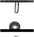
- the contact angle between a droplet (4 ⁇ L) of milliQ water and the disc support was measured with a FibroDat 1121/1122 system equipped with a CCD camera. According to the FibroDat software, the measured contact angle ( ⁇ ) was 116° ( Figure 1 ). Before treatment with 1H, 1H, 2H, 2H - perfluorodecyltriethoxysilane, the contact angle was too low to be measured by the FibroDat system ( ⁇ 10°) and the droplet was quickly disapering into the disc support.
- a porous ⁇ -alumina disc support as described in Example 1, was calcined in air at 500 °C for 5 hours. After filling the support with filtered distilled water by immersion, the support was immersed in an aqueous solution containing one wt.-% of a cationic polymer (Poly(dimethylamine-co-epichlorhydrin-co-ethylenediamine) with an average molecular weight of 75000, from Aldrich). The pH of the aqueous polymer solution had been adjusted to 8 using 25 wt.-% aqueous ammonia solution.
- a cationic polymer Poly(dimethylamine-co-epichlorhydrin-co-ethylenediamine
- the support was rinsed 4 times with a 0.1 M aqueous ammonia solution and subsequently, after drying in oven for 2 hours at 105 °C, the support was immersed into a 2.5 wt.-% ethanol solution of 1H, 1H, 2H, 2H - perfluorodecyltriethoxysilane for 1 hour. Thereafter, the support was dipped into ethanol (99.7 %) four times after which the ethanol was replaced by new ethanol. This procedure was repeated six times.
- the hydrophobic support was immersed in an aqueous dispersion containing 1 wt.-% silicalite-1 crystals with an average diameter of about 50 nm. Deposition of the crystals onto the support surface was allowed to proceed for 10 minutes. After rinsing with 0.1 M aqueous ammonia, the support was calcined in air at 500°C for 5 hours.
- a circular disc support of porous ⁇ -alumina (25 mm in diameter, 3 mm thick), provided with a 30 ⁇ m thick top layer of 100 nm pores and a 3 mm thick base layer with 3 ⁇ m pores was calcined in air at 500°C for 5 hours.
- the support was then treated by a masking procedure known in the art ( WO 00/53298 ) involving two steps; the first step implies that the top surface of the 100 nm pores was coated with a layer of poly (methyl methacrylate), in the second step the interior of the support was filled with molten hydrocarbon wax at elevetad temperature. The hydrocarbon wax solidified after cooling.
- the poly (methyl methacrylate) was dissolved in acetone and the surface rinsed with 0.1 M aqueous NH 3 before the contact angle between a droplet (4 ⁇ L) of milliQ water and the dry disc support was measured with a FibroDat 1121/1122 system equipped with a CCD camera.
- the support was treated with an aqueous solution adjusted to pH 8 containing 1 wt.-% cationic polymer (Poly(dimethylamine-co-epichlorhydrin-co-ethylenediamine) with an average molecular weight of 75000, from Aldrich) in order to reverse the charge of the support surface. Then the support was rinsed in 4 different 0.1 M aqueous ammonia solutions and dried on a laminar flow bench for 12 hours at ambient temperature.
- 1 wt.-% cationic polymer Poly(dimethylamine-co-epichlorhydrin-co-ethylenediamine) with an average molecular weight of 75000, from Aldrich
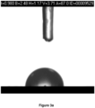
- the contact angle measured after treatment with cationic polymer was 87° ( Figure 3a ). This value shows that the support surface became hydrophilic after treatment with the cationic polymer solution.
- the treatment of the support with cationic polymer was repeated and excess polymer on the support surface rinsed away by dipping the support once into 0.1 M aqueous NH 3 before drying it on a laminar flow bench for 12 hours at ambient temperature. It is evident that less rinsing resulted in a contact angle of 64° and accordingly a more hydrophilic support surface due to higher concentration of cationic polymer on the support surface ( Figure 3b ).
- a circular disc support of porous ⁇ -alumina (25 mm in diameter, 3 mm thick), provided with a 30 ⁇ m thick top layer of 100 nm pores and a 3 mm thick base layer with 3 ⁇ m pores was calcined in air at 500°C for 5 hours.
- the calcined support was first immersed in 2.5 wt.-% of 1H, 1H, 2H, 2H - perfluoro decyltriethoxysilane in ethanol as solvent ( WO 2014140291 ). The immersion time was 1 hour. After this period of time, the support was rinsed with ethanol according to the procedure described in Example 1 and dried in oven at 105°C for 2 hours.
- the support was immersed in a 1 wt.-% aqueous dispersion containing silicalite-1 crystals with an average diameter of about 50 nm. Deposition of the crystals onto the support surface was allowed to proceed for 10 minutes. After rinsing with 0.1 M aqueous ammonia, the support was calcined in air at 500°C for 5 hours.
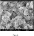
- the deposition of the molecular sieve crystals onto the support surface was examined with Scanning Electron Microscopy using a FEI Magellan 400 field emission instrument.
- the sample was not coated with any coating before the SEM image was recorded.
- the support surface was covered with a sub-monolayer of silicalite-1 crystals, a coverage not suitable to grow and intergrow a zeolite film.
- Some spots of the support were not covered with silicalite-1 crystals. These empty spots without seed crystals may result in pinholes in the synthesized membrane and/or prevent intergrowth of the crystals in the film.
- the tube was provided with a 30 ⁇ m thick inner layer with 100 nm pores and an outer layer with 3 ⁇ m pores.
- the calcined support was first immersed in 2.5 wt.-% of 1H, 1H, 2H, 2H - perfluoro decyltriethoxysilane in ethanol as solvent. The immersion time was 1 hour. After this period of time, the support was dipped into ethanol (99.7 %) four times after which the ethanol was replaced by new ethanol. This procedure was repeated six times.
- the hydrophobic tubular support was allowed to dry in oven at 105°C for 2 hours and then the support was immersed in an aqueous solution containing one wt.-% of a cationic polymer (Poly(dimethylamine-co-epichlorhydrin-co-ethylenediamine) with an average molecular weight of 75000, from Aldrich).
- the aqueous polymer solution was adjusted to pH 8 using 25 wt.-% aqueous ammonia solution.
- the support was rinsed with 0.1 M aqueous ammonia solution by dipping the support into the ammonia solution four times after which the solution was replaced by a fresh solution. This procedure was repeated four times.
- the tubular support was treated with wt.-% aqueous dispersion containing silicalite-1 crystals with an average diameter of about 50 nm. Deposition of the crystals onto the support surface was allowed to proceed for 10 minutes. After rinsing with 0.1 M aqueous ammonia, the support was immersed in a synthesis solution with the composition: 25 SiO 2 : 3 TPAOH: 100 EtOH: 1450 H 2 O and hydrothermally treated in an oil bath at 88°C for 71 hours. After cooling, the thin-film composite anisotropic membrane was rinsed with 0.1 M aqueous ammonia to remove loosely bound crystals and oligomers from the surface of the membrane.
- the support was then treated by a masking procedure known in the art ( WO 00/53298 ) involving two steps; the first step implies that the top surface of the 100 nm pores was coated with a thin layer of poly (methyl methacrylate), in the second step the remainder of the support was filled with hydrocarbon wax.
- the all of the poly(methyl methacrylate) was dissolved in acetone and the surface rinsed with 0.1 M aqueous NH 3 before the support was treated with an aqueous solution adjusted to pH 8 (using 25 wt.-% NH 3 (aq)) containing 1 wt.-% cationic polymer (Poly(dimethylamine-co-epichlorhydrin-co-ethylenediamine) with an average molecular weight of 75000, from Aldrich) in order to reverse the charge of the support surface.
- aqueous solution adjusted to pH 8 using 25 wt.-% NH 3 (aq)
- 1 wt.-% cationic polymer Poly(dimethylamine-co-epichlorhydrin-co-ethylenediamine) with an average molecular weight of 75000, from Aldrich
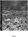
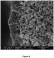
- a representative Scanning Electron Microscopy image of the cross section of the calcined film is shown in Figure 6 .
- Invasion from the synthesis solution could be detected; the pores between the alumina grains in the support are partially or completely filled with zeolite or silicates from the synthesis solution used for film growth. This is because poly (methyl methacrylate) penetrated into the 100 nm pores or the hydrocarbon wax did not reach completely up to the poly (methyl methacrylate) coating.
- the porosity of the alumina support typically is only about 40%, invasion will reduce the permeability of the membrane substantially. Also, invasion makes it difficult to optimize the thickness of the synthesized membrane and may also result in leaching of the support.
- the Si/AI ratio of the entire cross section of the film was measured using energy dispersive spectroscopy (EDS) with a method described in the art [ J. Membr. Sci. 360 (2010) 265-275 ]. Depending on the location, the Si/AI ratio varied in the range 45-133. This shows that the masking of the support was uneven. Althouh the synthesis mixture was free from aluminium, much aluminum was leached from the support and incorporated in the grown film due to the incomplete masking of the alumina support. Consequently, it is not possible to prepare MFI films with high Si/AI ratio on alumina supports by this prior art method.
- EDS energy dispersive spectroscopy
- a porous ⁇ -alumina disc support, as described in Example 1, was calcined in air at 500°C for 5 hours. After filling the support with distilled water, the support was immersed in a solution containing one wt.-% of a cationic polymer (Poly(dimethylamine-co-epichlorhydrin-co-ethylenediamine) with an average molecular weight of 75000, from Aldrich) dissolved in an aqueous ammonia (pH 8.5) solution.
- a cationic polymer Poly(dimethylamine-co-epichlorhydrin-co-ethylenediamine) with an average molecular weight of 75000, from Aldrich
- the support was rinsed in 0.1 M aqueous ammonia solution and subsequently, after drying for 2 hours on a hot plate (110 °C) placed in a laminar flow bench, the support was immersed completely in a 2.5 wt.-% ethanol solution of 1H, 1H, 2H, 2H - perfluorodecyltriethoxysilane for 1 hour. Thereafter, the support was dipped into ethanol (99.7 %) four times after which the ethanol was replaced by new ethanol. This procedure was repeated six times.
- the support was immersed completely in aqueous dispersion (pH 10) containing 1 wt.-% silicalite-1 crystals with an average diameter of about 50 nm. Deposition of the crystals onto the support surface was allowed to proceed for 10 minutes. After rinsing with a 0.1 M aqueous ammonia solution, the support was immersed completely in a synthesis solution with the molar composition: 25 SiO 2 : 3 TPAOH: 100 EtOH: 1500 H 2 O and hydrothermally treated in an oil bath at 100°C for 36 hours. After cooling, the sample was rinsed with 0.1 M aqueous NH 3 solution to remove loosely bound crystals and oligomers from the surface of the membrane.
- the Si/AI ratio of the entire cross section of the film was measured at various locations of the support using (EDS), a method described in the art [ J. Membr. Sci. 360 (2010) 265-275 ]. Depending on the location, the Si/AI ratio varied between 97 and 152.
- the Si/AI ratios measured with EDS in Example 6 are smaller than the Si/AI ratios measured with EDS in Example 7 and illustrates the possibility to prepare MFI films with higher Si/AI ratio (less hydrophilic characteristic) with the method disclosed herein as compared to prior art (Example 6).
- the support was provided with a 30 ⁇ m thick top-layer with 100 nm pores and an 1.5 mm thick base layer with 3 ⁇ m pores. In-between these layers, there is also a 30-40 ⁇ m thick layer of intermediate pore size.
- the porous support was filled with filtered distilled water and then immersed in an aqueous solution containing one wt.-% of cationic polymer (Poly(dimethylamine-co-epichlorhydrin-co-ethylenediamine) with an average molecular weight of 75000, from Aldrich) for 30 minutes.
- cationic polymer Poly(dimethylamine-co-epichlorhydrin-co-ethylenediamine
- the aqueous polymer solution was adjusted to pH 8 using 25 wt.-% aqueous ammonia solution.
- the tubular support was rinsed with filtered 0.1 M NH 3 solution, by dipping the ceramic tube 10 times in each of 6 Teflon tubes filled with filtered 0.1 M NH 3 solution, and then dried on a laminar flow bench for 12 hours. Thereafter the whole support was treated with filtered 2.5 wt.-% 1H, 1H, 2H, 2H - perfluoro decyltriethoxysilane in ethanol as solvent for 1 hour. After this treatment, the whole support was rinsed with filtered ethanol (99.7 %) for 1 hour (6 Teflon tubes with filtered ethanol x 10 min.
- the tubular support was treated with filtered one wt.-% aqueous dispersion containing silicalite-1 crystals (pH 10) with an average diameter of about 50 nm. Deposition of the crystals onto the substrate surface was allowed to proceed for 15 minutes. After rinsing with 0.1 M aqueous ammonia solution, the support was immersed in synthesis solution with the molar composition: 25 SiO 2 : 3 TPAOH: 100 EtOH: 1450 H 2 O and hydrothermally treated in an oil bath at 88°C for 71 hours.
- the sample was rinsed with filtered 0.1 M aqueous NH 3 to remove loosely bound crystals and oligomers from the surface of the membrane.
- the single gas helium permeance of the membrane before calcination was lower than 0.02 verifying that the membrane was essentially free from cracks and pinholes.
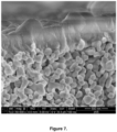
- FIG. 7 A representative Scanning Electron Microscopy image of the cross section of the calcined membrane is shown in Figure 7 .
- the pores of the support are fully open. No zeolite invasion of the support could be detected by recording numeros SEM images at various locations of the cross section, implying that synthesis solution could not penetrate through the hydrophobic barrier of the support.
- Figure 5b shows a plot of helium permeance vs. relative vapor pressure of n-hexane, as measured in a permporometry experiment, of the membrane prepared according to Example 8 in the present invention (lower trace).
- the tube was provided with a 30 ⁇ m thick inner layer with 100 nm pores and an 1.5 mm thick outer layer with 3 ⁇ m pores. In between these layers there is a 30-40 ⁇ m thick layer of intermediate pore size.
- the porous support was filled with filtered distilled water and then immersed in an aqueous solution containing one wt.-% of cationic polymer (Poly(dimethylamine-co-epichlorhydrin-co-ethylenediamine) with an average molecular weight of 75000, from Aldrich) for 30 minutes.
- cationic polymer Poly(dimethylamine-co-epichlorhydrin-co-ethylenediamine
- the aqueous polymer solution was adjusted to pH 8 using 25 wt.-% aqueous ammonia solution. Subsequently, the tubular support was rinsed with filtered 0.1 M NH 3 solution, by dipping the ceramic tube 10 times in each of 6 Teflon tubes filled with filtered 0.1 M NH 3 solution, and then dried on a laminar flow bench for 12 hours. Thereafter, the whole tube was treated with filtered 2.5 wt.-% 1H, 1H, 2H, 2H - perfluoro decyltriethoxysilane in ethanol as solvent for 1 hour.
- the whole support was rinsed with filtered ethanol (99.7 %) for 1 hour (6 Teflon tubes with filtered ethanol x 10 minutes in each tube) and dried on a laminar flow bench for 12 hours. Subsequently, the tubular support was treated with filtered one wt.-% aqueous dispersion containing silicalite-1 crystals (pH 10) with an average diameter of about 50 nm. Deposition of the crystals onto the substrate surface was allowed to proceed for 15 minutes.
- the support was immersed completely in synthesis solution with the molar composition: 25 SiO 2 : 3 TPAOH: 100 EtOH: 1450 H 2 O and hydrothermally treated in an autoclave at 88°C for 56 hours. After cooling, the sample was rinsed with filtered 0.1 M aqueous NH 3 to remove loosely bound crystals and oligomers from the surface of the membrane.
- the single gas helium permeance of the membrane before calcination was lower than 0.02, verifying that the membrane was free from large defects such as pinholes.
- FIG. 8 A representative Scanning Electron Microscopy image of the cross section of the calcined membrane is shown in Figure 8 .
- the pores of the support are fully open. No zeolite invasion of the support could be detected by recording numeros SEM images at various locations of the cross section, implying that synthesis solution could not penetrate through the hydrophobic barrier of the support. This illustrates that the method disclosed herein is suitable also for the preparation of large single channel membranes.
- the porous support was filled with filtered distilled water and then immersed in an aqueous solution containing one wt.-% of cationic polymer (Poly(dimethylamine-co-epichlorhydrin-co-ethylenediamine) with an average molecular weight of 75000, from Aldrich) for 30 minutes.
- cationic polymer Poly(dimethylamine-co-epichlorhydrin-co-ethylenediamine
- the aqueous polymer solution was adjusted to pH 8 using 25 wt.-% aqueous ammonia solution. Subsequently, the tubular support was rinsed with a filtered 0.1 M NH 3 solution, by dipping the ceramic tube 10 times in each of 6 Teflon tubes filled with filtered 0.1 M NH 3 solution, and then dried on a laminar flow bench for 12 hours. Thereafter, the support was imersed completely in filtered 2.5 wt.-% 1H, 1H, 2H, 2H - perfluoro decyltriethoxysilane in ethanol as solvent for 1 hour.
- the whole support was rinsed with filtered ethanol (99.7 %) for 1 hour (6 Teflon tubes with filtered ethanol x 10 minutes in each tube) and dried on a laminar flow bench for 12 hours. Subsequently, the tubular support was treated with filtered one wt.-% aqueous dispersion (pH 10) containing silicalite-1 crystals with an average diameter of about 50 nm. Deposition of the crystals onto the substrate surface was allowed to proceed for 15 minutes.
- the support After rinsing with 0.1 M aqueous ammonia solution, the support was immersed completely in a synthesis solution with the molar composition: 25 SiO 2 : 3 TPAOH: 100 EtOH: 1450 H 2 O and hydrothermally treated in an autoclave at 88°C for 56 hours. After cooling, the sample was rinsed with filtered 0.1 M aqueous NH 3 solution to remove loosely bound crystals and oligomers from the surface of the membrane and calcined in air at 500° C.
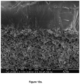
- FIG. 9 A representative Scanning Electron Microscopy image of the cross section of the calcined membrane is shown in Figure 9 .
- the pores of the support are fully open. No zeolite invasion of the support could be detected by recording numeros SEM images at various locations of the cross section, implying that synthesis solution could not penetrate through the hydrophobic barrier of the support. This illustrates that the method disclosed herein is suitable also for the preparation of large multi-channel membranes.
- a porous ⁇ -alumina disc support, as described in Example 1, was calcined in air at 500°C for 5 hours. After filling the support with distilled water, the support was immersed in a solution containing one wt.-% of a cationic polymer (Poly(dimethylamine-co-epichlorhydrin-co-ethylenediamine) with an average molecular weight of 75000, from Aldrich) dissolved in an aqueous ammonia (pH 8.5) solution.
- a cationic polymer Poly(dimethylamine-co-epichlorhydrin-co-ethylenediamine) with an average molecular weight of 75000, from Aldrich
- the support was rinsed in 0.1 M aqueous ammonia solution and subsequently, after drying for 2 hours on a hot plate (110 °C) placed in a laminar flow bench, the support was immersed completely in a 2.5 wt.-% ethanol solution of 1H, 1H, 2H, 2H - perfluorodecyltriethoxysilane for 1 hour. Thereafter, the support was dipped into ethanol (99.7 %) four times after which the ethanol was replaced by new ethanol. This procedure was repeated six times.
- the support After drying again for 2 hours on a hot plate (110 °C) placed in a laminar flow bench, the support was immersed completely in aqueous dispersion (pH 10) containing 1 wt.-% silicalite-1 crystals with an average diameter of about 50 nm. Deposition of the crystals onto the support surface was allowed to proceed for 10 minutes. After rinsing with 0.1 M aqueous ammonia, the support was immersed completely in a synthesis solution with the molar composition 25 SiO 2 : 0.25 Al 2 O 3 : 3 TPAOH: 1 Na 2 O: 100 EtOH: 1600 H 2 O: and hydrothermally treated in an oil bath at 100 °C for 22 hours.
- aqueous dispersion pH 10
- TPAOH 1 Na 2 O: 100 EtOH: 1600 H 2 O:
- Aluminum isopropoxide ( ⁇ 98.0%, Aldrich) was used as aluminum source to obtain a Si/AI ratio of 50 in the synthesis mixture and sodium hydroxide (NaOH, ⁇ 99.0, Merck) was used to increase the basicity of the solution.
- NaOH sodium hydroxide
- the membrane was rinsed with filtered 0.1 M aqueous NH 3 to remove loosely bound crystals and oligomers from the surface of the membrane and calcined in air at 500° C.
- FIG. 10a A representative Scanning Electron Microscopy image of the cross section of the resulting ZSM-5 membrane with an Si/AI ratio of 50 is shown in Figure 10a .
- the pores of the support are fully open, and no invasion of the support could be detected by recording numerous SEM images at various locations of the cross section, implying that synthesis solution could not penetrate through the hydrophobic barrier of the support.
- Figure 10 b shows the XRD pattern of the ZSM-5 membrane, measured with a PANalytical Empyrean X-ray Diffractometer.
- the membrane was prepared according to the present invention as described in Example 11.
- the diffraction pattern verifies the MFI structure and reflections from the MFI structure are labeled with the appropriate Miller indices, while reflections from the support are labelled with " ⁇ -Al 2 O 3 ".
- a porous ⁇ -alumina disc support, as described in Example 1, was calcined in air at 500°C for 5 hours. After filling the support with distilled water, the support was immersed in a solution containing one wt.-% of a cationic polymer (Poly(dimethylamine-co-epichlorhydrin-co-ethylenediamine) with an average molecular weight of 75000, from Aldrich) dissolved in aqueous ammonia (pH 8.5).
- a cationic polymer Poly(dimethylamine-co-epichlorhydrin-co-ethylenediamine) with an average molecular weight of 75000, from Aldrich
- the support was rinsed in 0.1 M aqueous ammonia solution and subsequently, after drying for 2 hours on a hot plate (110 °C) placed in a laminar flow bench, the support was immersed completely in a 2.5 wt.-% ethanol solution of 1H, 1H, 2H, 2H - perfluorodecyltriethoxysilane for 1 hour. Thereafter, the support was dipped into ethanol (99.7 %) four times after which the ethanol was replaced by new ethanol. This procedure was repeated six times.
- the support After drying again for 2 hours on a hot plate (110 °C) placed in a laminar flow bench, the support was immersed completely in aqueous dispersion (pH 10) containing 1 wt.-% silicalite-1 crystals with an average diameter of about 50 nm. Deposition of the crystals onto the support surface was allowed to proceed for 10 minutes. After rinsing with 0.1 M aqueous ammonia, the support was immersed completely in a synthesis solution with the molar composition 25 SiO 2 : 0.50 Al 2 O 3 : 3 TPAOH: 1 Na 2 O: 100 EtOH: 1600 H 2 O: and hydrothermally treated in an oil bath at 150 °C for 14 hours.
- Aluminum isopropoxide ( ⁇ 98.0%, Aldrich) was used as aluminum source to obtain a Si/AI ratio of 25 and sodium hydroxide (NaOH, ⁇ 99.0, Merck) was used to increase the basicity of the solution.
- NaOH sodium hydroxide
- the membrane was rinsed with filtered 0.1 M aqueous NH 3 to remove loosely bound crystals and oligomers from the surface of the membrane and calcined in air at 500° C.
- FIG. 11 A representative Scanning Electron Microscopy image of the cross section of the ZSM-5 membrane with an Si/AI ratio of 25 is shown in Figure 11 .
- the pores of the support are fully open, and no invasion of the support could be detected by recording numerous SEM images at various locations of the cross section, implying that synthesis solution could not penetrate through the hydrophobic barrier of the support.
- a cationic polymer Poly(dimethylamine-co-epichlorhydrin-co-ethylenediamine) with an average molecular weight of 75000, from Aldrich
- the support was rinsed in 0.1 M aqueous ammonia solution and subsequently, after drying in oven for 2 hours at 105 °C, the support was immersed into a 2.5 wt.-% ethanol solution of 1H, 1H, 2H, 2H - perfluoro decyltriethoxysilane for 1 hour. Thereafter, the support was dipped into ethanol (99.7 %) four times after which the ethanol was replaced by new ethanol. This procedure was repeated six times.
- the support was immersed in an aqueous dispersion containing 1 wt.-% chabazite crystals with an average diameter of about 178 nm according to dynamic light scattering.
- the chabazite crystals had been prepared from larger crystals by milling. Deposition of the crystals onto the support surface was allowed to proceed for 10 minutes.
- the support was immersed in a synthesis solution with the molar composition of 1 SiO 2 : 1,4 N, N, N-trimethyl-1-adamantyl ammonium fluoride: 8 H 2 O and hydrothermally treated in an oil bath at 160°C for 12 hours. After cooling, the sample was rinsed with a filtered 0.1 M aqueous NH 3 solution to remove loosely bound crystals and oligomers from the surface of the membrane.
- FIG. 12a A representative Scanning Electron Microscopy image of the cross section of the calcined CHA membrane is shown in Figure 12a .
- the pores of the support are fully open, and no invasion of the support could be detected.
- Numerous SEM images were recorded at various locations of the cross section, with similar results. This shows that the synthesis solution could not penetrate through the hydrophobic barrier of the support, even though the synthesis of the CHA zeolite membrane was carried out at high temperature and pressure in an autoclave.
- Figure 12b shows the XRD pattern of the CHA membrane, prepared according to the present invention as described in Example 13, verifying the CHA structure.
- the reflections from the CHA film are indexed by the appropriate Miller indices, while the reflection from the alumina support is indexed with " ⁇ -Al 2 O 3 ".
- a porous ⁇ -alumina disc substrate, as described in Example 1, was calcined in air at 500°C for 6 hours. After filling the support with distilled water, the support was immersed in a solution containing one wt.-% of a cationic polymer (Poly(dimethylamine-co-epichlorhydrin-co-ethylenediamine) with an average molecular weight of 75000, from Aldrich) dissolved in aqueous ammonia (pH 10).
- a cationic polymer Poly(dimethylamine-co-epichlorhydrin-co-ethylenediamine) with an average molecular weight of 75000, from Aldrich
- the support was rinsed in 0.1 M aqueous ammonia solution and subsequently, after drying in an oven for 2 hours at 105 °C, the support was immersed into a 2.5 wt.-% ethanol solution of 1H, 1H, 2H, 2H - perfluorodecyltriethoxysilane for 1 hour. Thereafter, the support was dipped into ethanol (99.7 %) four times after which the ethanol was replaced by new ethanol. This procedure was repeated six times. After drying in oven for 2 hours at 105°C, the support was immersed in an filtered (0.45 ⁇ m) acqueous dispersion of 0.5 wt.-% FAU crystals.
- the immersion time was 10 minutes. After the seeded support had been rinsed with filtered 0.1 M ammonia solution, it was immersed in a synthesis solution with the composition: 80 Na 2 O: 1 Al 2 O 3 : 9 SiO 2 : 5000 H 2 O and treated hydrothermally in an oil bath at 100°C for 3 hours. After cooling, the sample was rinsed with 0.1 M aqueous NH 3 to remove loosely bound crystals from the synthesis solution attached on the surface of the membrane.
- FIG. 13a shows the XRD pattern of the FAU membrane, synthesized according to Example 14, verifying the FAU structure. Reflections marked with "#" emanates from the FAU structure, while the reflection marked with "*" originates from the porous ⁇ -alumina support.
- a cationic polymer Poly(dimethylamine-co-epichlorhydrin-co-ethylenediamine) with an average molecular weight of 75000, from Aldrich
- the support was rinsed in 0.1 M aqueous ammonia solution and subsequently, after drying in oven for 2 hours at 105 °C, the support was immersed into a 2.5 wt.-% ethanol solution of 1H, 1H, 2H, 2H - perfluoro decyltriethoxysilane for 1 hour. Thereafter, the support was dipped into ethanol (99.7 %) four times after which the ethanol was replaced by new ethanol. This procedure was repeated six times.
- the support was immersed in an aqueous dispersion containing 1 wt.-% chabazite crystals with size between 20 and 300 nm according to dynamic light scattering. Deposition of the crystals onto the support surface was allowed to proceed for 10 minutes. After rinsing with a 0.1 M aqueous ammonia solution, the support was immersed in a synthesis solution with the molar composition of 1.0 SiO 2 : 0.35 N, N, N-trimethyl-1- adamantyl ammonium fluoride: 160.0 H 2 O and hydrothermally treated in an oil bath at 160°C for 36 hours. After cooling, the samples were rinsed with a filtered 0.1 M aqueous NH 3 solution to remove loosely bound crystals and oligomers from the surface of the membrane.
- a porous ⁇ -alumina tubular support according to Example 8 was prepared and seeded according to the method described in Example 8. After rinsing with 0.1 M aqueous ammonia solution, the support was immersed in a synthesis solution with the molar composition: 25 SiO 2 : 3 TPAOH: 100 EtOH: 1450 H 2 O and hydrothermally treated in an oil bath at 88°C for 71 hours. After cooling, the MFI membrane was rinsed with filtered 0.1 M aqueous NH 3 to remove loosely bound crystals and oligomers from the surface of the membrane. The single gas helium permeance of the MFI membrane before calcination was lower than 0.02 verifying that the membrane was essentially free from cracks and pinholes.
- Figure 15 shows a plot of helium permeance vs. relative vapor pressure of n-hexane as measured in a permporometry experiment of the MFI membrane prepared according to Example 16 is about 0.01 after calcination and a relative vapor pressure of 1, which is much lower than for a MFI membrane prepared according to prior art in Example 5.
Landscapes
- Chemical & Material Sciences (AREA)
- Chemical Kinetics & Catalysis (AREA)
- Organic Chemistry (AREA)
- Engineering & Computer Science (AREA)
- Materials Engineering (AREA)
- Crystallography & Structural Chemistry (AREA)
- Inorganic Chemistry (AREA)
- Analytical Chemistry (AREA)
- Manufacturing & Machinery (AREA)
- Geology (AREA)
- Life Sciences & Earth Sciences (AREA)
- Silicates, Zeolites, And Molecular Sieves (AREA)
- Separation Using Semi-Permeable Membranes (AREA)
- Solid-Sorbent Or Filter-Aiding Compositions (AREA)
Applications Claiming Priority (2)
| Application Number | Priority Date | Filing Date | Title |
|---|---|---|---|
| GBGB1714269.6A GB201714269D0 (en) | 2017-09-05 | 2017-09-05 | Methods for preparing supported zeolite films |
| PCT/EP2018/073913 WO2019048505A1 (en) | 2017-09-05 | 2018-09-05 | SUPPORTED ZEOLITE FILMS AND METHODS OF PREPARATION |
Publications (3)
| Publication Number | Publication Date |
|---|---|
| EP3678761A1 EP3678761A1 (en) | 2020-07-15 |
| EP3678761B1 true EP3678761B1 (en) | 2024-12-18 |
| EP3678761C0 EP3678761C0 (en) | 2024-12-18 |
Family
ID=60050609
Family Applications (1)
| Application Number | Title | Priority Date | Filing Date |
|---|---|---|---|
| EP18773942.0A Active EP3678761B1 (en) | 2017-09-05 | 2018-09-05 | Methods for preparing supported zeolite films |
Country Status (6)
| Country | Link |
|---|---|
| US (1) | US11554359B2 (enExample) |
| EP (1) | EP3678761B1 (enExample) |
| JP (1) | JP7247193B2 (enExample) |
| CN (1) | CN111065447B (enExample) |
| GB (1) | GB201714269D0 (enExample) |
| WO (1) | WO2019048505A1 (enExample) |
Families Citing this family (9)
| Publication number | Priority date | Publication date | Assignee | Title |
|---|---|---|---|---|
| KR102115301B1 (ko) * | 2019-03-18 | 2020-05-26 | 고려대학교 산학협력단 | 이종 제올라이트 분리막의 제조방법 |
| CN111924857B (zh) * | 2020-08-26 | 2023-02-21 | 威海太平洋新材料有限公司 | 一种球形ssz-13分子筛的合成方法 |
| CN113018905B (zh) * | 2021-03-03 | 2022-07-05 | 东阳市易源环保科技有限公司 | 一种基于硅胶和白土吸附回收的废油净化装置 |
| CN117083314A (zh) * | 2021-03-24 | 2023-11-17 | 科思创德国股份有限公司 | 一种用真空灌注工艺制备聚氨酯复合材料的方法 |
| EP4083101A1 (en) * | 2021-04-29 | 2022-11-02 | Covestro Deutschland AG | Method for preparing a polyurethane composite material by vacuum infusion process |
| CN116059844B (zh) * | 2021-10-31 | 2024-09-03 | 中国石油化工股份有限公司 | 一种全硅沸石分子筛膜的修饰方法及制备的膜和应用 |
| CN114479675B (zh) * | 2022-03-08 | 2023-05-16 | 昆山捷纳电子材料有限公司 | 一种用于光纤接头端面的抛光液组合物 |
| CN120882661A (zh) * | 2023-04-07 | 2025-10-31 | 东曹株式会社 | Mfi型沸石及其制造方法 |
| CN117190529B (zh) * | 2023-09-12 | 2025-01-17 | 中国科学院兰州化学物理研究所 | 一种辐射制冷装置及其在冰川保护中的应用 |
Family Cites Families (27)
| Publication number | Priority date | Publication date | Assignee | Title |
|---|---|---|---|---|
| US3702886A (en) | 1969-10-10 | 1972-11-14 | Mobil Oil Corp | Crystalline zeolite zsm-5 and method of preparing the same |
| US4061724A (en) | 1975-09-22 | 1977-12-06 | Union Carbide Corporation | Crystalline silica |
| WO1993001825A1 (fr) | 1991-07-19 | 1993-02-04 | Otsuka Pharmaceutical Co., Ltd. | Medicament antitumoral |
| SG49056A1 (en) | 1991-10-23 | 1998-05-18 | Exxon Chemical Patents Inc | Nanometer-sized molecular sieve crystals or agglomerates and processes for their production |
| SE9202518L (sv) | 1992-09-02 | 1994-03-03 | Jan Erik Otterstedt | Mikropartiklar |
| ATE168585T1 (de) | 1993-04-23 | 1998-08-15 | Exxon Chemical Patents Inc | Kristalline molekularsiebe enthaltende schichten und verfahren zu ihrer herstellung |
| EP0783457B1 (en) | 1995-07-10 | 2001-04-18 | Exxon Chemical Patents Inc. | Zeolites and processes for their manufacture |
| AU714585B2 (en) | 1995-07-10 | 2000-01-06 | Exxon Chemical Patents Inc. | Zeolites and processes for their manufacture |
| WO1997003021A1 (en) | 1995-07-10 | 1997-01-30 | Exxon Chemical Patents Inc. | Zeolites and processes for their manufacture |
| SE9600970D0 (sv) | 1996-03-14 | 1996-03-14 | Johan Sterte | Förfarande för framställning av mycket tunna filmer av molekylsiktar |
| US6183926B1 (en) | 1998-10-26 | 2001-02-06 | Ricoh Company, Ltd. | Toner and two-component developer for electrophotographic process and image formation method and image formation apparatus using the toner |
| GB9905561D0 (en) * | 1999-03-11 | 1999-05-05 | Exxon Chemical Patents Inc | Molecular sieve layers and process for their manufacture |
| GB9905560D0 (en) | 1999-03-11 | 1999-05-05 | Exxon Chemical Patents Inc | Process for the manufacture of supported materials |
| DE10056362A1 (de) * | 2000-11-14 | 2002-05-29 | Thomas Bein | Synthese und Stabilisierung von nanoskaligen Zeolithteilchen |
| JP2002214825A (ja) | 2001-01-17 | 2002-07-31 | Fuji Xerox Co Ltd | 電子写真用トナー、電子写真用現像剤、及び画像形成方法 |
| US20030228969A1 (en) * | 2002-06-11 | 2003-12-11 | Junhang Dong | Method for synthesizing zeolite membranes |
| US7357836B2 (en) * | 2003-03-06 | 2008-04-15 | University Of Massachusetts | Crystalline membranes |
| JP2009256592A (ja) | 2008-03-18 | 2009-11-05 | Fujifilm Corp | 多孔質膜 |
| KR100978490B1 (ko) * | 2008-05-21 | 2010-08-30 | 서강대학교산학협력단 | 다양한 두께를 갖는 모든 b-축이 기질에 대해서 수직으로배향된 MFI형 제올라이트 박막 및 그의 제조방법 |
| US8846558B2 (en) | 2008-07-18 | 2014-09-30 | Exxonmobil Research And Engineering Company | Functionalization of the internal surfaces of zeolites with alcohol compounds |
| US8702822B2 (en) | 2009-08-28 | 2014-04-22 | Regents Of The University Of Minnesota | Method and apparatus for producing a fuel from a biomass or bio-oil |
| JP5428014B2 (ja) * | 2009-12-25 | 2014-02-26 | 日本碍子株式会社 | ゼオライト膜の製造方法 |
| CN103084144B (zh) * | 2013-02-06 | 2014-11-05 | 中国科学院广州地球化学研究所 | 一种用于吸附挥发性有机污染物的硅藻土基多孔复合材料及其制备方法 |
| WO2014140296A1 (en) * | 2013-03-14 | 2014-09-18 | Jonas Hedlund | A method for producing zeolite crystals and/or zeolite-like crystals |
| WO2014140291A1 (en) | 2013-03-14 | 2014-09-18 | Jonas Hedlund | A method for producing a crystalline film of zeolite and/or zeolite like crystals on a porous substrate |
| US10173903B2 (en) * | 2014-06-16 | 2019-01-08 | University Of Houston System | Zeolite compositions and methods for tailoring zeolite crystal habits with growth modifiers |
| US20170056834A1 (en) * | 2015-08-24 | 2017-03-02 | Ohio State Innovation Foundation | Multilayer coatings and methods of making and using thereof |
-
2017
- 2017-09-05 GB GBGB1714269.6A patent/GB201714269D0/en not_active Ceased
-
2018
- 2018-09-05 US US16/644,019 patent/US11554359B2/en active Active
- 2018-09-05 CN CN201880057766.XA patent/CN111065447B/zh active Active
- 2018-09-05 WO PCT/EP2018/073913 patent/WO2019048505A1/en not_active Ceased
- 2018-09-05 JP JP2020533365A patent/JP7247193B2/ja active Active
- 2018-09-05 EP EP18773942.0A patent/EP3678761B1/en active Active
Also Published As
| Publication number | Publication date |
|---|---|
| US11554359B2 (en) | 2023-01-17 |
| US20200246775A1 (en) | 2020-08-06 |
| CN111065447A (zh) | 2020-04-24 |
| CN111065447B (zh) | 2022-10-21 |
| WO2019048505A1 (en) | 2019-03-14 |
| GB201714269D0 (en) | 2017-10-18 |
| JP2020532487A (ja) | 2020-11-12 |
| EP3678761A1 (en) | 2020-07-15 |
| JP7247193B2 (ja) | 2023-03-28 |
| EP3678761C0 (en) | 2024-12-18 |
Similar Documents
| Publication | Publication Date | Title |
|---|---|---|
| EP3678761B1 (en) | Methods for preparing supported zeolite films | |
| EP3001819B1 (en) | A method for producing a crystalline film of zeolite and/or zeolite like crystals on a porous substrate | |
| EP0481660B1 (en) | Zeo-type Membranes | |
| JP4511637B2 (ja) | モレキュラーシーブフィルムの調製方法 | |
| EP3225297B1 (en) | Use of a porous support-cha zeolite membrane composite for separation of a gas mixture | |
| JP5108525B2 (ja) | ゼオライト膜の製造方法 | |
| EP2066427A1 (en) | Zeolite membrane structures and methods of making zeolite membrane structures | |
| WO2015021099A1 (en) | Metal doped zeolite membrane for gas separation | |
| JP3128517B2 (ja) | ゼオライト分離膜及びその製造方法 | |
| JP5481075B2 (ja) | ゼオライト膜の製造方法 | |
| EP0481659A1 (en) | Deposition process | |
| JP6163719B2 (ja) | 硫化水素の分離方法 | |
| JP2003238147A (ja) | Mfi型ゼオライトの合成方法、mfi型ゼオライト結晶、mfi型ゼオライトが塗布された基材、ゼオライト膜の製造方法、および分離方法 | |
| EP1661616B1 (en) | Gas separating body and method for producing same | |
| JP2004002160A (ja) | ゼオライト結晶のコーティング方法、ゼオライト結晶がコーティングされた基材、ゼオライト膜の製造方法、ゼオライト膜、およびゼオライト膜を利用した分離方法 | |
| KR100903952B1 (ko) | 친수성 제올라이트 분리막의 제조방법 | |
| JP2004344755A (ja) | ゼオライト複合薄膜 | |
| JP2008018387A (ja) | 多孔質基材への種結晶塗布方法 |
Legal Events
| Date | Code | Title | Description |
|---|---|---|---|
| STAA | Information on the status of an ep patent application or granted ep patent |
Free format text: STATUS: UNKNOWN |
|
| STAA | Information on the status of an ep patent application or granted ep patent |
Free format text: STATUS: THE INTERNATIONAL PUBLICATION HAS BEEN MADE |
|
| PUAI | Public reference made under article 153(3) epc to a published international application that has entered the european phase |
Free format text: ORIGINAL CODE: 0009012 |
|
| STAA | Information on the status of an ep patent application or granted ep patent |
Free format text: STATUS: REQUEST FOR EXAMINATION WAS MADE |
|
| 17P | Request for examination filed |
Effective date: 20200331 |
|
| AK | Designated contracting states |
Kind code of ref document: A1 Designated state(s): AL AT BE BG CH CY CZ DE DK EE ES FI FR GB GR HR HU IE IS IT LI LT LU LV MC MK MT NL NO PL PT RO RS SE SI SK SM TR |
|
| AX | Request for extension of the european patent |
Extension state: BA ME |
|
| DAV | Request for validation of the european patent (deleted) | ||
| DAX | Request for extension of the european patent (deleted) | ||
| STAA | Information on the status of an ep patent application or granted ep patent |
Free format text: STATUS: EXAMINATION IS IN PROGRESS |
|
| 17Q | First examination report despatched |
Effective date: 20210419 |
|
| P01 | Opt-out of the competence of the unified patent court (upc) registered |
Effective date: 20230528 |
|
| REG | Reference to a national code |
Ref country code: DE Ref legal event code: R079 Free format text: PREVIOUS MAIN CLASS: B01D0069040000 Ipc: B01J0035590000 Ref document number: 602018077736 Country of ref document: DE |
|
| GRAP | Despatch of communication of intention to grant a patent |
Free format text: ORIGINAL CODE: EPIDOSNIGR1 |
|
| STAA | Information on the status of an ep patent application or granted ep patent |
Free format text: STATUS: GRANT OF PATENT IS INTENDED |
|
| INTG | Intention to grant announced |
Effective date: 20240503 |
|
| RIC1 | Information provided on ipc code assigned before grant |
Ipc: B01D 71/60 20060101ALI20240422BHEP Ipc: B01D 63/06 20060101ALI20240422BHEP Ipc: B01J 20/18 20060101ALI20240422BHEP Ipc: B01D 67/00 20060101ALI20240422BHEP Ipc: B01J 20/28 20060101ALI20240422BHEP Ipc: B01D 71/02 20060101ALI20240422BHEP Ipc: B01D 69/04 20060101ALI20240422BHEP Ipc: B01D 69/10 20060101ALI20240422BHEP Ipc: B01D 71/00 20060101ALI20240422BHEP Ipc: B01J 35/59 20240101AFI20240422BHEP |
|
| GRAS | Grant fee paid |
Free format text: ORIGINAL CODE: EPIDOSNIGR3 |
|
| GRAA | (expected) grant |
Free format text: ORIGINAL CODE: 0009210 |
|
| STAA | Information on the status of an ep patent application or granted ep patent |
Free format text: STATUS: THE PATENT HAS BEEN GRANTED |
|
| RAP1 | Party data changed (applicant data changed or rights of an application transferred) |
Owner name: ZEOMEM SWEDEN AB |
|
| RIN1 | Information on inventor provided before grant (corrected) |
Inventor name: YU, LIANG Inventor name: HOLMGREN, ALLAN Inventor name: HEDLUND, JONAS |
|
| AK | Designated contracting states |
Kind code of ref document: B1 Designated state(s): AL AT BE BG CH CY CZ DE DK EE ES FI FR GB GR HR HU IE IS IT LI LT LU LV MC MK MT NL NO PL PT RO RS SE SI SK SM TR |
|
| REG | Reference to a national code |
Ref country code: GB Ref legal event code: FG4D |
|
| REG | Reference to a national code |
Ref country code: CH Ref legal event code: EP |
|
| REG | Reference to a national code |
Ref country code: DE Ref legal event code: R096 Ref document number: 602018077736 Country of ref document: DE |
|
| REG | Reference to a national code |
Ref country code: IE Ref legal event code: FG4D |
|
| U01 | Request for unitary effect filed |
Effective date: 20250116 |
|
| P04 | Withdrawal of opt-out of the competence of the unified patent court (upc) registered |
Free format text: CASE NUMBER: APP_3002/2025 Effective date: 20250118 |
|
| U07 | Unitary effect registered |
Designated state(s): AT BE BG DE DK EE FI FR IT LT LU LV MT NL PT RO SE SI Effective date: 20250122 |
|
| PG25 | Lapsed in a contracting state [announced via postgrant information from national office to epo] |
Ref country code: HR Free format text: LAPSE BECAUSE OF FAILURE TO SUBMIT A TRANSLATION OF THE DESCRIPTION OR TO PAY THE FEE WITHIN THE PRESCRIBED TIME-LIMIT Effective date: 20241218 |
|
| PG25 | Lapsed in a contracting state [announced via postgrant information from national office to epo] |
Ref country code: GR Free format text: LAPSE BECAUSE OF FAILURE TO SUBMIT A TRANSLATION OF THE DESCRIPTION OR TO PAY THE FEE WITHIN THE PRESCRIBED TIME-LIMIT Effective date: 20250319 |
|
| PG25 | Lapsed in a contracting state [announced via postgrant information from national office to epo] |
Ref country code: RS Free format text: LAPSE BECAUSE OF FAILURE TO SUBMIT A TRANSLATION OF THE DESCRIPTION OR TO PAY THE FEE WITHIN THE PRESCRIBED TIME-LIMIT Effective date: 20250318 |
|
| PG25 | Lapsed in a contracting state [announced via postgrant information from national office to epo] |
Ref country code: SM Free format text: LAPSE BECAUSE OF FAILURE TO SUBMIT A TRANSLATION OF THE DESCRIPTION OR TO PAY THE FEE WITHIN THE PRESCRIBED TIME-LIMIT Effective date: 20241218 |
|
| PG25 | Lapsed in a contracting state [announced via postgrant information from national office to epo] |
Ref country code: PL Free format text: LAPSE BECAUSE OF FAILURE TO SUBMIT A TRANSLATION OF THE DESCRIPTION OR TO PAY THE FEE WITHIN THE PRESCRIBED TIME-LIMIT Effective date: 20241218 |
|
| PG25 | Lapsed in a contracting state [announced via postgrant information from national office to epo] |
Ref country code: ES Free format text: LAPSE BECAUSE OF FAILURE TO SUBMIT A TRANSLATION OF THE DESCRIPTION OR TO PAY THE FEE WITHIN THE PRESCRIBED TIME-LIMIT Effective date: 20241218 |
|
| PG25 | Lapsed in a contracting state [announced via postgrant information from national office to epo] |
Ref country code: IS Free format text: LAPSE BECAUSE OF FAILURE TO SUBMIT A TRANSLATION OF THE DESCRIPTION OR TO PAY THE FEE WITHIN THE PRESCRIBED TIME-LIMIT Effective date: 20250418 |
|
| PG25 | Lapsed in a contracting state [announced via postgrant information from national office to epo] |
Ref country code: SK Free format text: LAPSE BECAUSE OF FAILURE TO SUBMIT A TRANSLATION OF THE DESCRIPTION OR TO PAY THE FEE WITHIN THE PRESCRIBED TIME-LIMIT Effective date: 20241218 |
|
| PG25 | Lapsed in a contracting state [announced via postgrant information from national office to epo] |
Ref country code: CZ Free format text: LAPSE BECAUSE OF FAILURE TO SUBMIT A TRANSLATION OF THE DESCRIPTION OR TO PAY THE FEE WITHIN THE PRESCRIBED TIME-LIMIT Effective date: 20241218 |
|
| PGFP | Annual fee paid to national office [announced via postgrant information from national office to epo] |
Ref country code: NO Payment date: 20250917 Year of fee payment: 8 |
|
| PGFP | Annual fee paid to national office [announced via postgrant information from national office to epo] |
Ref country code: GB Payment date: 20250929 Year of fee payment: 8 |
|
| PGFP | Annual fee paid to national office [announced via postgrant information from national office to epo] |
Ref country code: IE Payment date: 20250917 Year of fee payment: 8 |
|
| PLBE | No opposition filed within time limit |
Free format text: ORIGINAL CODE: 0009261 |
|
| STAA | Information on the status of an ep patent application or granted ep patent |
Free format text: STATUS: NO OPPOSITION FILED WITHIN TIME LIMIT |
|
| U20 | Renewal fee for the european patent with unitary effect paid |
Year of fee payment: 8 Effective date: 20250930 |
|
| 26N | No opposition filed |
Effective date: 20250919 |