EP3001819B1 - A method for producing a crystalline film of zeolite and/or zeolite like crystals on a porous substrate - Google Patents
A method for producing a crystalline film of zeolite and/or zeolite like crystals on a porous substrate Download PDFInfo
- Publication number
- EP3001819B1 EP3001819B1 EP14711475.5A EP14711475A EP3001819B1 EP 3001819 B1 EP3001819 B1 EP 3001819B1 EP 14711475 A EP14711475 A EP 14711475A EP 3001819 B1 EP3001819 B1 EP 3001819B1
- Authority
- EP
- European Patent Office
- Prior art keywords
- zeolite
- substrate
- crystals
- hydrophobic
- porous
- Prior art date
- Legal status (The legal status is an assumption and is not a legal conclusion. Google has not performed a legal analysis and makes no representation as to the accuracy of the status listed.)
- Active
Links
- 239000000758 substrate Substances 0.000 title claims description 311
- 239000013078 crystal Substances 0.000 title claims description 159
- 239000010457 zeolite Substances 0.000 title claims description 146
- HNPSIPDUKPIQMN-UHFFFAOYSA-N dioxosilane;oxo(oxoalumanyloxy)alumane Chemical compound O=[Si]=O.O=[Al]O[Al]=O HNPSIPDUKPIQMN-UHFFFAOYSA-N 0.000 title claims description 118
- 229910021536 Zeolite Inorganic materials 0.000 title claims description 115
- 238000004519 manufacturing process Methods 0.000 title claims description 8
- 238000000034 method Methods 0.000 claims description 115
- 230000002209 hydrophobic effect Effects 0.000 claims description 88
- 239000000203 mixture Substances 0.000 claims description 42
- 239000000463 material Substances 0.000 claims description 33
- 239000003795 chemical substances by application Substances 0.000 claims description 27
- 238000000151 deposition Methods 0.000 claims description 26
- OGQYPPBGSLZBEG-UHFFFAOYSA-N dimethyl(dioctadecyl)azanium Chemical compound CCCCCCCCCCCCCCCCCC[N+](C)(C)CCCCCCCCCCCCCCCCCC OGQYPPBGSLZBEG-UHFFFAOYSA-N 0.000 claims description 19
- 229920006317 cationic polymer Polymers 0.000 claims description 16
- 229920000831 ionic polymer Polymers 0.000 claims description 13
- 150000001875 compounds Chemical class 0.000 claims description 12
- 238000001354 calcination Methods 0.000 claims description 10
- 238000009877 rendering Methods 0.000 claims description 10
- MLXDKRSDUJLNAB-UHFFFAOYSA-N triethoxy(3,3,4,4,5,5,6,6,7,7,8,8,9,9,10,10,10-heptadecafluorodecyl)silane Chemical compound CCO[Si](OCC)(OCC)CCC(F)(F)C(F)(F)C(F)(F)C(F)(F)C(F)(F)C(F)(F)C(F)(F)C(F)(F)F MLXDKRSDUJLNAB-UHFFFAOYSA-N 0.000 claims description 10
- UNYSKUBLZGJSLV-UHFFFAOYSA-L calcium;1,3,5,2,4,6$l^{2}-trioxadisilaluminane 2,4-dioxide;dihydroxide;hexahydrate Chemical compound O.O.O.O.O.O.[OH-].[OH-].[Ca+2].O=[Si]1O[Al]O[Si](=O)O1.O=[Si]1O[Al]O[Si](=O)O1 UNYSKUBLZGJSLV-UHFFFAOYSA-L 0.000 claims description 6
- 229910052676 chabazite Inorganic materials 0.000 claims description 6
- 125000000217 alkyl group Chemical class 0.000 claims description 5
- JEWHCPOELGJVCB-UHFFFAOYSA-N aluminum;calcium;oxido-[oxido(oxo)silyl]oxy-oxosilane;potassium;sodium;tridecahydrate Chemical compound O.O.O.O.O.O.O.O.O.O.O.O.O.[Na].[Al].[K].[Ca].[O-][Si](=O)O[Si]([O-])=O JEWHCPOELGJVCB-UHFFFAOYSA-N 0.000 claims description 5
- 229910001743 phillipsite Inorganic materials 0.000 claims description 5
- 150000001768 cations Chemical class 0.000 claims description 4
- 150000003839 salts Chemical class 0.000 claims description 4
- 229910052665 sodalite Inorganic materials 0.000 claims description 4
- 150000001450 anions Chemical class 0.000 claims description 3
- 229910001657 ferrierite group Inorganic materials 0.000 claims description 3
- VIFIHLXNOOCGLJ-UHFFFAOYSA-N trichloro(3,3,4,4,5,5,6,6,7,7,8,8,9,9,10,10,10-heptadecafluorodecyl)silane Chemical compound FC(F)(F)C(F)(F)C(F)(F)C(F)(F)C(F)(F)C(F)(F)C(F)(F)C(F)(F)CC[Si](Cl)(Cl)Cl VIFIHLXNOOCGLJ-UHFFFAOYSA-N 0.000 claims description 3
- NBXZNTLFQLUFES-UHFFFAOYSA-N triethoxy(propyl)silane Chemical compound CCC[Si](OCC)(OCC)OCC NBXZNTLFQLUFES-UHFFFAOYSA-N 0.000 claims description 3
- BVQYIDJXNYHKRK-UHFFFAOYSA-N trimethoxy(3,3,4,4,5,5,6,6,7,7,8,8,8-tridecafluorooctyl)silane Chemical compound CO[Si](OC)(OC)CCC(F)(F)C(F)(F)C(F)(F)C(F)(F)C(F)(F)C(F)(F)F BVQYIDJXNYHKRK-UHFFFAOYSA-N 0.000 claims description 3
- OYOGCAUNFUJOMO-UHFFFAOYSA-N trimethyl(octyl)silane Chemical compound CCCCCCCC[Si](C)(C)C OYOGCAUNFUJOMO-UHFFFAOYSA-N 0.000 claims description 3
- FGUUSXIOTUKUDN-IBGZPJMESA-N C1(=CC=CC=C1)N1C2=C(NC([C@H](C1)NC=1OC(=NN=1)C1=CC=CC=C1)=O)C=CC=C2 Chemical compound C1(=CC=CC=C1)N1C2=C(NC([C@H](C1)NC=1OC(=NN=1)C1=CC=CC=C1)=O)C=CC=C2 FGUUSXIOTUKUDN-IBGZPJMESA-N 0.000 claims description 2
- 125000005210 alkyl ammonium group Chemical group 0.000 claims description 2
- 125000005600 alkyl phosphonate group Chemical group 0.000 claims description 2
- 150000001735 carboxylic acids Chemical class 0.000 claims description 2
- 229910052680 mordenite Inorganic materials 0.000 claims description 2
- LFQSCWFLJHTTHZ-UHFFFAOYSA-N Ethanol Chemical compound CCO LFQSCWFLJHTTHZ-UHFFFAOYSA-N 0.000 description 80
- 239000010408 film Substances 0.000 description 75
- 239000000243 solution Substances 0.000 description 63
- 239000012528 membrane Substances 0.000 description 55
- 239000010410 layer Substances 0.000 description 51
- 239000011148 porous material Substances 0.000 description 50
- 230000015572 biosynthetic process Effects 0.000 description 42
- 239000002356 single layer Substances 0.000 description 42
- 238000003786 synthesis reaction Methods 0.000 description 40
- 230000009545 invasion Effects 0.000 description 29
- PNEYBMLMFCGWSK-UHFFFAOYSA-N Alumina Chemical compound [O-2].[O-2].[O-2].[Al+3].[Al+3] PNEYBMLMFCGWSK-UHFFFAOYSA-N 0.000 description 26
- 239000006185 dispersion Substances 0.000 description 26
- VYPSYNLAJGMNEJ-UHFFFAOYSA-N silicon dioxide Inorganic materials O=[Si]=O VYPSYNLAJGMNEJ-UHFFFAOYSA-N 0.000 description 23
- XLYOFNOQVPJJNP-UHFFFAOYSA-N water Substances O XLYOFNOQVPJJNP-UHFFFAOYSA-N 0.000 description 23
- 230000008021 deposition Effects 0.000 description 22
- 230000000873 masking effect Effects 0.000 description 21
- VHUUQVKOLVNVRT-UHFFFAOYSA-N Ammonium hydroxide Chemical compound [NH4+].[OH-] VHUUQVKOLVNVRT-UHFFFAOYSA-N 0.000 description 20
- 235000011114 ammonium hydroxide Nutrition 0.000 description 20
- 230000005661 hydrophobic surface Effects 0.000 description 17
- CSCPPACGZOOCGX-UHFFFAOYSA-N Acetone Chemical compound CC(C)=O CSCPPACGZOOCGX-UHFFFAOYSA-N 0.000 description 16
- 239000002808 molecular sieve Substances 0.000 description 16
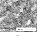
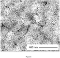
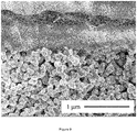
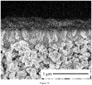
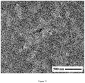
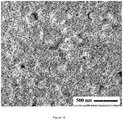
- 238000001878 scanning electron micrograph Methods 0.000 description 16
- URGAHOPLAPQHLN-UHFFFAOYSA-N sodium aluminosilicate Chemical compound [Na+].[Al+3].[O-][Si]([O-])=O.[O-][Si]([O-])=O URGAHOPLAPQHLN-UHFFFAOYSA-N 0.000 description 16
- QGZKDVFQNNGYKY-UHFFFAOYSA-N ammonia Natural products N QGZKDVFQNNGYKY-UHFFFAOYSA-N 0.000 description 14
- 241000894007 species Species 0.000 description 14
- 238000000926 separation method Methods 0.000 description 13
- NLXLAEXVIDQMFP-UHFFFAOYSA-N Ammonium chloride Substances [NH4+].[Cl-] NLXLAEXVIDQMFP-UHFFFAOYSA-N 0.000 description 12
- -1 Na+ Chemical class 0.000 description 12
- 230000004048 modification Effects 0.000 description 12
- 238000012986 modification Methods 0.000 description 12
- 229920000642 polymer Polymers 0.000 description 12
- 239000001993 wax Substances 0.000 description 11
- 238000004626 scanning electron microscopy Methods 0.000 description 10
- CURLTUGMZLYLDI-UHFFFAOYSA-N Carbon dioxide Chemical compound O=C=O CURLTUGMZLYLDI-UHFFFAOYSA-N 0.000 description 9
- HEMHJVSKTPXQMS-UHFFFAOYSA-M Sodium hydroxide Chemical compound [OH-].[Na+] HEMHJVSKTPXQMS-UHFFFAOYSA-M 0.000 description 9
- 238000007654 immersion Methods 0.000 description 9
- 239000000377 silicon dioxide Substances 0.000 description 9
- 239000000126 substance Substances 0.000 description 9
- 125000004429 atom Chemical group 0.000 description 8
- 239000007789 gas Substances 0.000 description 8
- 238000002360 preparation method Methods 0.000 description 8
- XUIMIQQOPSSXEZ-UHFFFAOYSA-N Silicon Chemical compound [Si] XUIMIQQOPSSXEZ-UHFFFAOYSA-N 0.000 description 7
- 229910052782 aluminium Inorganic materials 0.000 description 7
- 230000004888 barrier function Effects 0.000 description 7
- 230000003993 interaction Effects 0.000 description 7
- 239000013081 microcrystal Substances 0.000 description 7
- 229910000069 nitrogen hydride Inorganic materials 0.000 description 7
- 229910052710 silicon Inorganic materials 0.000 description 7
- 239000002904 solvent Substances 0.000 description 7
- 239000010409 thin film Substances 0.000 description 7
- 238000001816 cooling Methods 0.000 description 6
- 238000001035 drying Methods 0.000 description 6
- 238000010335 hydrothermal treatment Methods 0.000 description 6
- 229920003229 poly(methyl methacrylate) Polymers 0.000 description 6
- 239000004926 polymethyl methacrylate Substances 0.000 description 6
- 239000010703 silicon Substances 0.000 description 6
- OKTJSMMVPCPJKN-UHFFFAOYSA-N Carbon Chemical compound [C] OKTJSMMVPCPJKN-UHFFFAOYSA-N 0.000 description 5
- MCMNRKCIXSYSNV-UHFFFAOYSA-N Zirconium dioxide Chemical compound O=[Zr]=O MCMNRKCIXSYSNV-UHFFFAOYSA-N 0.000 description 5
- XAGFODPZIPBFFR-UHFFFAOYSA-N aluminium Chemical compound [Al] XAGFODPZIPBFFR-UHFFFAOYSA-N 0.000 description 5
- 239000004411 aluminium Substances 0.000 description 5
- 239000007864 aqueous solution Substances 0.000 description 5
- 229910002092 carbon dioxide Inorganic materials 0.000 description 5
- 238000005342 ion exchange Methods 0.000 description 5
- 239000007788 liquid Substances 0.000 description 5
- 238000010899 nucleation Methods 0.000 description 5
- 239000012466 permeate Substances 0.000 description 5
- 239000007787 solid Substances 0.000 description 5
- 238000006555 catalytic reaction Methods 0.000 description 4
- 239000011248 coating agent Substances 0.000 description 4
- 238000000576 coating method Methods 0.000 description 4
- 229910052681 coesite Inorganic materials 0.000 description 4
- 229910052906 cristobalite Inorganic materials 0.000 description 4
- 239000012153 distilled water Substances 0.000 description 4
- 230000005518 electrochemistry Effects 0.000 description 4
- 238000005516 engineering process Methods 0.000 description 4
- 230000004907 flux Effects 0.000 description 4
- 229910052751 metal Inorganic materials 0.000 description 4
- 239000002184 metal Substances 0.000 description 4
- 239000007858 starting material Substances 0.000 description 4
- 229910052682 stishovite Inorganic materials 0.000 description 4
- LPSKDVINWQNWFE-UHFFFAOYSA-M tetrapropylazanium;hydroxide Chemical compound [OH-].CCC[N+](CCC)(CCC)CCC LPSKDVINWQNWFE-UHFFFAOYSA-M 0.000 description 4
- 229910052905 tridymite Inorganic materials 0.000 description 4
- 239000004215 Carbon black (E152) Substances 0.000 description 3
- BOTDANWDWHJENH-UHFFFAOYSA-N Tetraethyl orthosilicate Chemical compound CCO[Si](OCC)(OCC)OCC BOTDANWDWHJENH-UHFFFAOYSA-N 0.000 description 3
- 150000001343 alkyl silanes Chemical class 0.000 description 3
- 229940077484 ammonium bromide Drugs 0.000 description 3
- 125000000129 anionic group Chemical group 0.000 description 3
- 229910052799 carbon Inorganic materials 0.000 description 3
- 239000001569 carbon dioxide Substances 0.000 description 3
- 239000003054 catalyst Substances 0.000 description 3
- 230000001186 cumulative effect Effects 0.000 description 3
- PLMFYJJFUUUCRZ-UHFFFAOYSA-M decyltrimethylammonium bromide Chemical compound [Br-].CCCCCCCCCC[N+](C)(C)C PLMFYJJFUUUCRZ-UHFFFAOYSA-M 0.000 description 3
- 239000000835 fiber Substances 0.000 description 3
- 238000011049 filling Methods 0.000 description 3
- 239000012530 fluid Substances 0.000 description 3
- XPFVYQJUAUNWIW-UHFFFAOYSA-N furfuryl alcohol Chemical compound OCC1=CC=CO1 XPFVYQJUAUNWIW-UHFFFAOYSA-N 0.000 description 3
- 229910052677 heulandite Inorganic materials 0.000 description 3
- 229930195733 hydrocarbon Natural products 0.000 description 3
- 150000002430 hydrocarbons Chemical class 0.000 description 3
- 229910052500 inorganic mineral Inorganic materials 0.000 description 3
- 150000002500 ions Chemical class 0.000 description 3
- 239000011707 mineral Substances 0.000 description 3
- 239000003921 oil Substances 0.000 description 3
- 235000012239 silicon dioxide Nutrition 0.000 description 3
- LYCAIKOWRPUZTN-UHFFFAOYSA-N Ethylene glycol Chemical compound OCCO LYCAIKOWRPUZTN-UHFFFAOYSA-N 0.000 description 2
- 241000264877 Hippospongia communis Species 0.000 description 2
- UFHFLCQGNIYNRP-UHFFFAOYSA-N Hydrogen Chemical compound [H][H] UFHFLCQGNIYNRP-UHFFFAOYSA-N 0.000 description 2
- KKCBUQHMOMHUOY-UHFFFAOYSA-N Na2O Inorganic materials [O-2].[Na+].[Na+] KKCBUQHMOMHUOY-UHFFFAOYSA-N 0.000 description 2
- PXHVJJICTQNCMI-UHFFFAOYSA-N Nickel Chemical compound [Ni] PXHVJJICTQNCMI-UHFFFAOYSA-N 0.000 description 2
- BPQQTUXANYXVAA-UHFFFAOYSA-N Orthosilicate Chemical compound [O-][Si]([O-])([O-])[O-] BPQQTUXANYXVAA-UHFFFAOYSA-N 0.000 description 2
- GWEVSGVZZGPLCZ-UHFFFAOYSA-N Titan oxide Chemical compound O=[Ti]=O GWEVSGVZZGPLCZ-UHFFFAOYSA-N 0.000 description 2
- 239000005083 Zinc sulfide Substances 0.000 description 2
- 239000003463 adsorbent Substances 0.000 description 2
- AZDRQVAHHNSJOQ-UHFFFAOYSA-N alumane Chemical group [AlH3] AZDRQVAHHNSJOQ-UHFFFAOYSA-N 0.000 description 2
- SMZOGRDCAXLAAR-UHFFFAOYSA-N aluminium isopropoxide Chemical compound [Al+3].CC(C)[O-].CC(C)[O-].CC(C)[O-] SMZOGRDCAXLAAR-UHFFFAOYSA-N 0.000 description 2
- 229910000323 aluminium silicate Inorganic materials 0.000 description 2
- SWLVFNYSXGMGBS-UHFFFAOYSA-N ammonium bromide Chemical compound [NH4+].[Br-] SWLVFNYSXGMGBS-UHFFFAOYSA-N 0.000 description 2
- 229960001040 ammonium chloride Drugs 0.000 description 2
- 235000019270 ammonium chloride Nutrition 0.000 description 2
- 229910052908 analcime Inorganic materials 0.000 description 2
- 125000002091 cationic group Chemical group 0.000 description 2
- 239000002178 crystalline material Substances 0.000 description 2
- 238000009792 diffusion process Methods 0.000 description 2
- 238000007598 dipping method Methods 0.000 description 2
- 238000004090 dissolution Methods 0.000 description 2
- 230000001747 exhibiting effect Effects 0.000 description 2
- NBVXSUQYWXRMNV-UHFFFAOYSA-N fluoromethane Chemical compound FC NBVXSUQYWXRMNV-UHFFFAOYSA-N 0.000 description 2
- 229910052732 germanium Inorganic materials 0.000 description 2
- 239000010439 graphite Substances 0.000 description 2
- 229910002804 graphite Inorganic materials 0.000 description 2
- 239000001257 hydrogen Substances 0.000 description 2
- 229910052739 hydrogen Inorganic materials 0.000 description 2
- 239000012535 impurity Substances 0.000 description 2
- 239000013067 intermediate product Substances 0.000 description 2
- 238000002386 leaching Methods 0.000 description 2
- 150000002739 metals Chemical class 0.000 description 2
- 238000002156 mixing Methods 0.000 description 2
- 229910052674 natrolite Inorganic materials 0.000 description 2
- 238000012856 packing Methods 0.000 description 2
- 239000012071 phase Substances 0.000 description 2
- 230000008569 process Effects 0.000 description 2
- 239000000047 product Substances 0.000 description 2
- BDERNNFJNOPAEC-UHFFFAOYSA-N propan-1-ol Chemical compound CCCO BDERNNFJNOPAEC-UHFFFAOYSA-N 0.000 description 2
- 239000010453 quartz Substances 0.000 description 2
- 230000003068 static effect Effects 0.000 description 2
- 229910052678 stilbite Inorganic materials 0.000 description 2
- 239000000725 suspension Substances 0.000 description 2
- JOXIMZWYDAKGHI-UHFFFAOYSA-N toluene-4-sulfonic acid Chemical compound CC1=CC=C(S(O)(=O)=O)C=C1 JOXIMZWYDAKGHI-UHFFFAOYSA-N 0.000 description 2
- NMEPHPOFYLLFTK-UHFFFAOYSA-N trimethoxy(octyl)silane Chemical compound CCCCCCCC[Si](OC)(OC)OC NMEPHPOFYLLFTK-UHFFFAOYSA-N 0.000 description 2
- DRDVZXDWVBGGMH-UHFFFAOYSA-N zinc;sulfide Chemical compound [S-2].[Zn+2] DRDVZXDWVBGGMH-UHFFFAOYSA-N 0.000 description 2
- PFNQVRZLDWYSCW-UHFFFAOYSA-N (fluoren-9-ylideneamino) n-naphthalen-1-ylcarbamate Chemical compound C12=CC=CC=C2C2=CC=CC=C2C1=NOC(=O)NC1=CC=CC2=CC=CC=C12 PFNQVRZLDWYSCW-UHFFFAOYSA-N 0.000 description 1
- QTRSWYWKHYAKEO-UHFFFAOYSA-N 1,1,2,2,3,3,4,4,5,5,6,6,7,7,8,8,9,9,10,10,10-henicosafluorodecyl-tris(1,1,2,2,2-pentafluoroethoxy)silane Chemical compound FC(F)(F)C(F)(F)O[Si](OC(F)(F)C(F)(F)F)(OC(F)(F)C(F)(F)F)C(F)(F)C(F)(F)C(F)(F)C(F)(F)C(F)(F)C(F)(F)C(F)(F)C(F)(F)C(F)(F)C(F)(F)F QTRSWYWKHYAKEO-UHFFFAOYSA-N 0.000 description 1
- DDFHBQSCUXNBSA-UHFFFAOYSA-N 5-(5-carboxythiophen-2-yl)thiophene-2-carboxylic acid Chemical compound S1C(C(=O)O)=CC=C1C1=CC=C(C(O)=O)S1 DDFHBQSCUXNBSA-UHFFFAOYSA-N 0.000 description 1
- CMUSFXMSPXHHLB-UHFFFAOYSA-N 8,8,8-trimethoxyoctylsilane Chemical compound COC(OC)(OC)CCCCCCC[SiH3] CMUSFXMSPXHHLB-UHFFFAOYSA-N 0.000 description 1
- 239000005995 Aluminium silicate Substances 0.000 description 1
- CPELXLSAUQHCOX-UHFFFAOYSA-M Bromide Chemical compound [Br-] CPELXLSAUQHCOX-UHFFFAOYSA-M 0.000 description 1
- 229920000049 Carbon (fiber) Polymers 0.000 description 1
- 229920003043 Cellulose fiber Polymers 0.000 description 1
- 239000005046 Chlorosilane Substances 0.000 description 1
- KRHYYFGTRYWZRS-UHFFFAOYSA-M Fluoride anion Chemical compound [F-] KRHYYFGTRYWZRS-UHFFFAOYSA-M 0.000 description 1
- PXGOKWXKJXAPGV-UHFFFAOYSA-N Fluorine Chemical compound FF PXGOKWXKJXAPGV-UHFFFAOYSA-N 0.000 description 1
- ZLMJMSJWJFRBEC-UHFFFAOYSA-N Potassium Chemical compound [K] ZLMJMSJWJFRBEC-UHFFFAOYSA-N 0.000 description 1
- 239000006087 Silane Coupling Agent Substances 0.000 description 1
- 229910000831 Steel Inorganic materials 0.000 description 1
- 239000004809 Teflon Substances 0.000 description 1
- 229920006362 Teflon® Polymers 0.000 description 1
- 238000002441 X-ray diffraction Methods 0.000 description 1
- 150000004645 aluminates Chemical class 0.000 description 1
- PZZYQPZGQPZBDN-UHFFFAOYSA-N aluminium silicate Chemical compound O=[Al]O[Si](=O)O[Al]=O PZZYQPZGQPZBDN-UHFFFAOYSA-N 0.000 description 1
- 235000012211 aluminium silicate Nutrition 0.000 description 1
- JYIBXUUINYLWLR-UHFFFAOYSA-N aluminum;calcium;potassium;silicon;sodium;trihydrate Chemical compound O.O.O.[Na].[Al].[Si].[K].[Ca] JYIBXUUINYLWLR-UHFFFAOYSA-N 0.000 description 1
- 150000001412 amines Chemical group 0.000 description 1
- 238000013459 approach Methods 0.000 description 1
- 239000003125 aqueous solvent Substances 0.000 description 1
- 229910052790 beryllium Inorganic materials 0.000 description 1
- 238000009835 boiling Methods 0.000 description 1
- 229910052796 boron Inorganic materials 0.000 description 1
- 125000004432 carbon atom Chemical group C* 0.000 description 1
- 239000004917 carbon fiber Substances 0.000 description 1
- 230000003197 catalytic effect Effects 0.000 description 1
- 239000000919 ceramic Substances 0.000 description 1
- 230000008859 change Effects 0.000 description 1
- 238000007385 chemical modification Methods 0.000 description 1
- KOPOQZFJUQMUML-UHFFFAOYSA-N chlorosilane Chemical class Cl[SiH3] KOPOQZFJUQMUML-UHFFFAOYSA-N 0.000 description 1
- 229910001603 clinoptilolite Inorganic materials 0.000 description 1
- 239000008119 colloidal silica Substances 0.000 description 1
- 230000000052 comparative effect Effects 0.000 description 1
- 239000002131 composite material Substances 0.000 description 1
- 238000011109 contamination Methods 0.000 description 1
- 229910052878 cordierite Inorganic materials 0.000 description 1
- 229910052593 corundum Inorganic materials 0.000 description 1
- 238000002425 crystallisation Methods 0.000 description 1
- 230000008025 crystallization Effects 0.000 description 1
- 230000007423 decrease Effects 0.000 description 1
- 230000003247 decreasing effect Effects 0.000 description 1
- 230000002950 deficient Effects 0.000 description 1
- 229910003460 diamond Inorganic materials 0.000 description 1
- 239000010432 diamond Substances 0.000 description 1
- JSKIRARMQDRGJZ-UHFFFAOYSA-N dimagnesium dioxido-bis[(1-oxido-3-oxo-2,4,6,8,9-pentaoxa-1,3-disila-5,7-dialuminabicyclo[3.3.1]nonan-7-yl)oxy]silane Chemical compound [Mg++].[Mg++].[O-][Si]([O-])(O[Al]1O[Al]2O[Si](=O)O[Si]([O-])(O1)O2)O[Al]1O[Al]2O[Si](=O)O[Si]([O-])(O1)O2 JSKIRARMQDRGJZ-UHFFFAOYSA-N 0.000 description 1
- 239000000428 dust Substances 0.000 description 1
- 230000009881 electrostatic interaction Effects 0.000 description 1
- 125000001301 ethoxy group Chemical group [H]C([H])([H])C([H])([H])O* 0.000 description 1
- 239000002657 fibrous material Substances 0.000 description 1
- 239000011737 fluorine Substances 0.000 description 1
- 229910052731 fluorine Inorganic materials 0.000 description 1
- 229910021485 fumed silica Inorganic materials 0.000 description 1
- 229910052733 gallium Inorganic materials 0.000 description 1
- GNPVGFCGXDBREM-UHFFFAOYSA-N germanium atom Chemical compound [Ge] GNPVGFCGXDBREM-UHFFFAOYSA-N 0.000 description 1
- 239000011521 glass Substances 0.000 description 1
- 239000003365 glass fiber Substances 0.000 description 1
- 239000003673 groundwater Substances 0.000 description 1
- 150000004820 halides Chemical class 0.000 description 1
- 238000010438 heat treatment Methods 0.000 description 1
- 239000001307 helium Substances 0.000 description 1
- 229910052734 helium Inorganic materials 0.000 description 1
- SWQJXJOGLNCZEY-UHFFFAOYSA-N helium atom Chemical compound [He] SWQJXJOGLNCZEY-UHFFFAOYSA-N 0.000 description 1
- KLHSDMQFUVANEB-MELZOAELSA-L hexadecyl-[(2r,3r)-4-[hexadecyl(dimethyl)azaniumyl]-2,3-dimethoxybutyl]-dimethylazanium;dibromide Chemical compound [Br-].[Br-].CCCCCCCCCCCCCCCC[N+](C)(C)C[C@@H](OC)[C@H](OC)C[N+](C)(C)CCCCCCCCCCCCCCCC KLHSDMQFUVANEB-MELZOAELSA-L 0.000 description 1
- 125000001183 hydrocarbyl group Chemical group 0.000 description 1
- 230000005660 hydrophilic surface Effects 0.000 description 1
- 238000005216 hydrothermal crystallization Methods 0.000 description 1
- 238000001027 hydrothermal synthesis Methods 0.000 description 1
- XLYOFNOQVPJJNP-UHFFFAOYSA-M hydroxide Chemical compound [OH-] XLYOFNOQVPJJNP-UHFFFAOYSA-M 0.000 description 1
- 150000004679 hydroxides Chemical class 0.000 description 1
- 125000002887 hydroxy group Chemical group [H]O* 0.000 description 1
- WGCNASOHLSPBMP-UHFFFAOYSA-N hydroxyacetaldehyde Natural products OCC=O WGCNASOHLSPBMP-UHFFFAOYSA-N 0.000 description 1
- 238000005470 impregnation Methods 0.000 description 1
- 229910052809 inorganic oxide Inorganic materials 0.000 description 1
- 229910052909 inorganic silicate Inorganic materials 0.000 description 1
- 229910052742 iron Inorganic materials 0.000 description 1
- 239000007791 liquid phase Substances 0.000 description 1
- 230000007246 mechanism Effects 0.000 description 1
- 229910001092 metal group alloy Inorganic materials 0.000 description 1
- 229910044991 metal oxide Inorganic materials 0.000 description 1
- 150000004706 metal oxides Chemical class 0.000 description 1
- 229910052914 metal silicate Inorganic materials 0.000 description 1
- 239000012229 microporous material Substances 0.000 description 1
- 230000001089 mineralizing effect Effects 0.000 description 1
- 238000002715 modification method Methods 0.000 description 1
- VMWJCFLUSKZZDX-UHFFFAOYSA-N n,n-dimethylmethanamine Chemical compound [CH2]N(C)C VMWJCFLUSKZZDX-UHFFFAOYSA-N 0.000 description 1
- 229910052759 nickel Inorganic materials 0.000 description 1
- 229910000510 noble metal Inorganic materials 0.000 description 1
- 125000004430 oxygen atom Chemical group O* 0.000 description 1
- RVTZCBVAJQQJTK-UHFFFAOYSA-N oxygen(2-);zirconium(4+) Chemical compound [O-2].[O-2].[Zr+4] RVTZCBVAJQQJTK-UHFFFAOYSA-N 0.000 description 1
- 239000012188 paraffin wax Substances 0.000 description 1
- 230000036961 partial effect Effects 0.000 description 1
- 230000035515 penetration Effects 0.000 description 1
- 125000004437 phosphorous atom Chemical group 0.000 description 1
- 229910052698 phosphorus Inorganic materials 0.000 description 1
- 239000004033 plastic Substances 0.000 description 1
- 229920003023 plastic Polymers 0.000 description 1
- 239000003880 polar aprotic solvent Substances 0.000 description 1
- 229920005594 polymer fiber Polymers 0.000 description 1
- 229910052700 potassium Inorganic materials 0.000 description 1
- 239000011591 potassium Substances 0.000 description 1
- 239000000843 powder Substances 0.000 description 1
- 239000010970 precious metal Substances 0.000 description 1
- 238000002203 pretreatment Methods 0.000 description 1
- 125000001453 quaternary ammonium group Chemical group 0.000 description 1
- 239000002994 raw material Substances 0.000 description 1
- 239000011541 reaction mixture Substances 0.000 description 1
- 230000009467 reduction Effects 0.000 description 1
- 230000002829 reductive effect Effects 0.000 description 1
- 239000012465 retentate Substances 0.000 description 1
- 230000002441 reversible effect Effects 0.000 description 1
- 239000011435 rock Substances 0.000 description 1
- 229910052594 sapphire Inorganic materials 0.000 description 1
- 150000004756 silanes Chemical class 0.000 description 1
- 150000004760 silicates Chemical class 0.000 description 1
- 238000001179 sorption measurement Methods 0.000 description 1
- 239000010935 stainless steel Substances 0.000 description 1
- 229910001220 stainless steel Inorganic materials 0.000 description 1
- 239000010959 steel Substances 0.000 description 1
- 238000003756 stirring Methods 0.000 description 1
- 238000001308 synthesis method Methods 0.000 description 1
- 230000002194 synthesizing effect Effects 0.000 description 1
- 229910052645 tectosilicate Inorganic materials 0.000 description 1
- 125000005207 tetraalkylammonium group Chemical group 0.000 description 1
- JRMUNVKIHCOMHV-UHFFFAOYSA-M tetrabutylammonium bromide Chemical compound [Br-].CCCC[N+](CCCC)(CCCC)CCCC JRMUNVKIHCOMHV-UHFFFAOYSA-M 0.000 description 1
- 229910052719 titanium Inorganic materials 0.000 description 1
- 238000012546 transfer Methods 0.000 description 1
- 239000012808 vapor phase Substances 0.000 description 1
- 235000012431 wafers Nutrition 0.000 description 1
- 238000005406 washing Methods 0.000 description 1
- 238000009736 wetting Methods 0.000 description 1
- 229910001845 yogo sapphire Inorganic materials 0.000 description 1
Images


Classifications
-
- B—PERFORMING OPERATIONS; TRANSPORTING
- B01—PHYSICAL OR CHEMICAL PROCESSES OR APPARATUS IN GENERAL
- B01J—CHEMICAL OR PHYSICAL PROCESSES, e.g. CATALYSIS OR COLLOID CHEMISTRY; THEIR RELEVANT APPARATUS
- B01J20/00—Solid sorbent compositions or filter aid compositions; Sorbents for chromatography; Processes for preparing, regenerating or reactivating thereof
- B01J20/30—Processes for preparing, regenerating, or reactivating
- B01J20/32—Impregnating or coating ; Solid sorbent compositions obtained from processes involving impregnating or coating
- B01J20/3231—Impregnating or coating ; Solid sorbent compositions obtained from processes involving impregnating or coating characterised by the coating or impregnating layer
- B01J20/3242—Layers with a functional group, e.g. an affinity material, a ligand, a reactant or a complexing group
- B01J20/3244—Non-macromolecular compounds
- B01J20/3246—Non-macromolecular compounds having a well defined chemical structure
-
- B—PERFORMING OPERATIONS; TRANSPORTING
- B01—PHYSICAL OR CHEMICAL PROCESSES OR APPARATUS IN GENERAL
- B01D—SEPARATION
- B01D53/00—Separation of gases or vapours; Recovering vapours of volatile solvents from gases; Chemical or biological purification of waste gases, e.g. engine exhaust gases, smoke, fumes, flue gases, aerosols
- B01D53/22—Separation of gases or vapours; Recovering vapours of volatile solvents from gases; Chemical or biological purification of waste gases, e.g. engine exhaust gases, smoke, fumes, flue gases, aerosols by diffusion
- B01D53/228—Separation of gases or vapours; Recovering vapours of volatile solvents from gases; Chemical or biological purification of waste gases, e.g. engine exhaust gases, smoke, fumes, flue gases, aerosols by diffusion characterised by specific membranes
-
- B—PERFORMING OPERATIONS; TRANSPORTING
- B01—PHYSICAL OR CHEMICAL PROCESSES OR APPARATUS IN GENERAL
- B01D—SEPARATION
- B01D67/00—Processes specially adapted for manufacturing semi-permeable membranes for separation processes or apparatus
- B01D67/0039—Inorganic membrane manufacture
- B01D67/0051—Inorganic membrane manufacture by controlled crystallisation, e,.g. hydrothermal growth
-
- B—PERFORMING OPERATIONS; TRANSPORTING
- B01—PHYSICAL OR CHEMICAL PROCESSES OR APPARATUS IN GENERAL
- B01D—SEPARATION
- B01D69/00—Semi-permeable membranes for separation processes or apparatus characterised by their form, structure or properties; Manufacturing processes specially adapted therefor
- B01D69/10—Supported membranes; Membrane supports
- B01D69/105—Support pretreatment
-
- B—PERFORMING OPERATIONS; TRANSPORTING
- B01—PHYSICAL OR CHEMICAL PROCESSES OR APPARATUS IN GENERAL
- B01D—SEPARATION
- B01D71/00—Semi-permeable membranes for separation processes or apparatus characterised by the material; Manufacturing processes specially adapted therefor
- B01D71/02—Inorganic material
- B01D71/028—Molecular sieves
- B01D71/0281—Zeolites
-
- B—PERFORMING OPERATIONS; TRANSPORTING
- B01—PHYSICAL OR CHEMICAL PROCESSES OR APPARATUS IN GENERAL
- B01J—CHEMICAL OR PHYSICAL PROCESSES, e.g. CATALYSIS OR COLLOID CHEMISTRY; THEIR RELEVANT APPARATUS
- B01J20/00—Solid sorbent compositions or filter aid compositions; Sorbents for chromatography; Processes for preparing, regenerating or reactivating thereof
- B01J20/02—Solid sorbent compositions or filter aid compositions; Sorbents for chromatography; Processes for preparing, regenerating or reactivating thereof comprising inorganic material
- B01J20/10—Solid sorbent compositions or filter aid compositions; Sorbents for chromatography; Processes for preparing, regenerating or reactivating thereof comprising inorganic material comprising silica or silicate
- B01J20/16—Alumino-silicates
- B01J20/165—Natural alumino-silicates, e.g. zeolites
-
- B—PERFORMING OPERATIONS; TRANSPORTING
- B01—PHYSICAL OR CHEMICAL PROCESSES OR APPARATUS IN GENERAL
- B01J—CHEMICAL OR PHYSICAL PROCESSES, e.g. CATALYSIS OR COLLOID CHEMISTRY; THEIR RELEVANT APPARATUS
- B01J21/00—Catalysts comprising the elements, oxides, or hydroxides of magnesium, boron, aluminium, carbon, silicon, titanium, zirconium, or hafnium
- B01J21/02—Boron or aluminium; Oxides or hydroxides thereof
- B01J21/04—Alumina
-
- B—PERFORMING OPERATIONS; TRANSPORTING
- B01—PHYSICAL OR CHEMICAL PROCESSES OR APPARATUS IN GENERAL
- B01J—CHEMICAL OR PHYSICAL PROCESSES, e.g. CATALYSIS OR COLLOID CHEMISTRY; THEIR RELEVANT APPARATUS
- B01J29/00—Catalysts comprising molecular sieves
- B01J29/03—Catalysts comprising molecular sieves not having base-exchange properties
- B01J29/035—Microporous crystalline materials not having base exchange properties, such as silica polymorphs, e.g. silicalites
-
- B—PERFORMING OPERATIONS; TRANSPORTING
- B01—PHYSICAL OR CHEMICAL PROCESSES OR APPARATUS IN GENERAL
- B01J—CHEMICAL OR PHYSICAL PROCESSES, e.g. CATALYSIS OR COLLOID CHEMISTRY; THEIR RELEVANT APPARATUS
- B01J29/00—Catalysts comprising molecular sieves
- B01J29/04—Catalysts comprising molecular sieves having base-exchange properties, e.g. crystalline zeolites
- B01J29/06—Crystalline aluminosilicate zeolites; Isomorphous compounds thereof
- B01J29/08—Crystalline aluminosilicate zeolites; Isomorphous compounds thereof of the faujasite type, e.g. type X or Y
- B01J29/084—Y-type faujasite
-
- B—PERFORMING OPERATIONS; TRANSPORTING
- B01—PHYSICAL OR CHEMICAL PROCESSES OR APPARATUS IN GENERAL
- B01J—CHEMICAL OR PHYSICAL PROCESSES, e.g. CATALYSIS OR COLLOID CHEMISTRY; THEIR RELEVANT APPARATUS
- B01J37/00—Processes, in general, for preparing catalysts; Processes, in general, for activation of catalysts
- B01J37/02—Impregnation, coating or precipitation
- B01J37/0201—Impregnation
- B01J37/0207—Pretreatment of the support
-
- B—PERFORMING OPERATIONS; TRANSPORTING
- B01—PHYSICAL OR CHEMICAL PROCESSES OR APPARATUS IN GENERAL
- B01D—SEPARATION
- B01D2323/00—Details relating to membrane preparation
- B01D2323/04—Hydrophobization
-
- B—PERFORMING OPERATIONS; TRANSPORTING
- B01—PHYSICAL OR CHEMICAL PROCESSES OR APPARATUS IN GENERAL
- B01D—SEPARATION
- B01D2323/00—Details relating to membrane preparation
- B01D2323/24—Use of template or surface directing agents [SDA]
-
- B—PERFORMING OPERATIONS; TRANSPORTING
- B01—PHYSICAL OR CHEMICAL PROCESSES OR APPARATUS IN GENERAL
- B01D—SEPARATION
- B01D2323/00—Details relating to membrane preparation
- B01D2323/40—Details relating to membrane preparation in-situ membrane formation
-
- B—PERFORMING OPERATIONS; TRANSPORTING
- B01—PHYSICAL OR CHEMICAL PROCESSES OR APPARATUS IN GENERAL
- B01D—SEPARATION
- B01D2323/00—Details relating to membrane preparation
- B01D2323/46—Impregnation
-
- B—PERFORMING OPERATIONS; TRANSPORTING
- B01—PHYSICAL OR CHEMICAL PROCESSES OR APPARATUS IN GENERAL
- B01D—SEPARATION
- B01D2323/00—Details relating to membrane preparation
- B01D2323/50—Control of the membrane preparation process
-
- B—PERFORMING OPERATIONS; TRANSPORTING
- B01—PHYSICAL OR CHEMICAL PROCESSES OR APPARATUS IN GENERAL
- B01J—CHEMICAL OR PHYSICAL PROCESSES, e.g. CATALYSIS OR COLLOID CHEMISTRY; THEIR RELEVANT APPARATUS
- B01J2229/00—Aspects of molecular sieve catalysts not covered by B01J29/00
- B01J2229/30—After treatment, characterised by the means used
- B01J2229/32—Reaction with silicon compounds, e.g. TEOS, siliconfluoride
-
- B—PERFORMING OPERATIONS; TRANSPORTING
- B01—PHYSICAL OR CHEMICAL PROCESSES OR APPARATUS IN GENERAL
- B01J—CHEMICAL OR PHYSICAL PROCESSES, e.g. CATALYSIS OR COLLOID CHEMISTRY; THEIR RELEVANT APPARATUS
- B01J2229/00—Aspects of molecular sieve catalysts not covered by B01J29/00
- B01J2229/60—Synthesis on support
- B01J2229/64—Synthesis on support in or on refractory materials
-
- B01J35/59—
-
- B—PERFORMING OPERATIONS; TRANSPORTING
- B01—PHYSICAL OR CHEMICAL PROCESSES OR APPARATUS IN GENERAL
- B01J—CHEMICAL OR PHYSICAL PROCESSES, e.g. CATALYSIS OR COLLOID CHEMISTRY; THEIR RELEVANT APPARATUS
- B01J37/00—Processes, in general, for preparing catalysts; Processes, in general, for activation of catalysts
- B01J37/02—Impregnation, coating or precipitation
- B01J37/0201—Impregnation
- B01J37/0209—Impregnation involving a reaction between the support and a fluid
Definitions
- the present invention relates to the field of films of zeolites and zeolite-like crystals, more specifically to the pretreatment of porous substrates onto which films can be grown and the deposition of seed crystals on the substrates, which is an essential step for the preparation of thin films.
- These materials find use in the fields of membrane separation, sensor technology, catalysis, ion exchange, and electrochemistry.
- Zeolites and zeolite-like materials are microporous materials with well-defined pores up to 13 ⁇ in diameter. Many molecules, whether in the gas or liquid phase, both inorganic and organic, have dimensions that fall within this range. Selecting a molecular sieve with a suitable pore size therefore allows separation of a molecule from a mixture based on the size of the molecule, which explains why zeolites and zeolite-like materials also are denoted "molecular sieves". In addition to this separation mechanism, where only molecules smaller than the pores of the molecular sieve can permeate, the pores within the material can separate molecular components having different adsorption and/or diffusion properties.
- the well-defined pore system of the molecular sieve enables selective ion exchange of charged species and selective catalysis.
- significant properties in addition to the micropore diameter are important, for instance, ion exchange capacity, specific surface area and acidity.
- Molecular sieves can be classified in various categories, for example according to their chemical composition and their structural properties.
- a group of molecular sieves of particular interest is the group comprising zeolites and zeolite-like materials.
- Zeolites and zeolite-like materials do not comprise an easily definable family of crystalline solids.
- the Structure Commission of the International Zeolite Association has presently approved more than 200 different zeolite framework types and assigned a 3-letter code to each framework.
- a criterion for distinguishing zeolites and zeolite-like materials from denser tectosilicates is based on the framework density, the number of tetrahedrally coordinated framework atoms per 1000 ⁇ 3 .
- the tetrahedrally coordinated framework atoms are also denoted T-atoms.
- the maximum framework density for zeolites and zeolite-like materials ranges from 19 to over 21 tetrahedrally coordinated framework atoms per 1000 ⁇ 3 , depending on the type of smallest ring present, whereas the minimum for denser structures ranges from 20 to 22.
- the Structure Commission maintains a zeolite structure database accessible via the internet [http://www.iza-structure.org/] and is also regularly revising and publishing the Atlas of Zeolite Framework Types. The 6th revised edition of the Atlas was published in 2007 [ Ch. Baerlocher, L. B. Mc Cusker, D. H. Olson. Atlas of Zeolite Framework Types, 6th Ed., 2007, Elsevier, ISBN 978-0-444-53064-6 ].
- Zeolite frameworks are built from TO 4 tetrahedra and the T-atoms are usually silicon and aluminium atoms, but zeolite frameworks can also be prepared from only SiO 4 thetrahedra.
- the T atoms are aluminium and phosphorous atoms.
- there are many more possibilities and atoms such as Si, Al, P, Ga, Ge, B, Be, Ti, Fe etc. can serve as T-atoms in zeolite frameworks.
- Zeolites and zeolite-like materials are microporous solids with a very regular pore structure of molecular dimensions.
- the dimensions of the channels control the maximum size of the molecular or ionic species that can enter the pores of a zeolite.
- the aperture of the channels are conventionally defined by the ring size, where, for example, the term "8-ring" refers to a closed loop that is built from 8 T-atoms and 8 oxygen atoms.
- Zeolites and zeolite like materials have a porous structure that can accommodate a wide variety of cations, such as Na + , K + , Ca 2+ , Mg 2+ and others. These positive ions can readily be exchanged, which explains why zeolites can serve as ion exchangers.
- Natural zeolite minerals are usually formed where volcanic rocks and ash layers react with alkaline groundwater. Naturally occurring zeolites are rarely pure and are contaminated to varying degrees by other minerals, metals, quartz, or other zeolites. For this reason, naturally occurring zeolites are excluded from many important commercial applications where uniformity and purity are essential. Some of the more common zeolites found as minerals in nature are (3-letter codes within brackets) analcime (ANA), chabazite (CHA), clinoptilolite (HEU), heulandite (HEU), natrolite (NAT), phillipsite (PHI), and stilbite (STI).
- ANA analcime
- CHA chabazite
- HEU clinoptilolite
- HEU heulandite
- NAT natrolite
- PHI phillipsite
- STI stilbite
- Zeolites and zeolite like materials can also be prepared synthetically.
- a frequently prepared zeolite framework is the MFI framework, which has 10 T-atoms in the ring and thereby a suitable pore size for many applications.
- This framework can be prepared in pure silica form, i.e. the T-atoms are only silicon atoms. In this case, the structure is denoted silicalite-1. However, if some of the silicon atoms are replaced with aluminium atoms, the structure is denoted ZSM-5.
- Templates or structure directing agents are added to the reaction mixture in the synthesis of zeolites and zeolite like materials to direct the crystallization to the desired framework. For example tetrapropyl ammonium hydroxide is often used as a template in the synthesis of MFI zeolite.
- Substrates coated with thin films find their applications in for example the fields of membrane separation, sensor technology, catalysis, electrochemistry, ion exchange.
- the film When the film is prepared on a porous substrate using hydrothermal synthesis techniques, a number of problems may arise. Firstly, species from synthesis solution used for growth of zeolites and zeolite-like materials may invade and be deposited within the porous substrate, resulting in reduction of the porosity of the substrate implying reduced permeation of gas or liquid molecules through the complete structure. Secondly, the substrate material may not be inert under the synthesis conditions used resulting in dissolution of atoms from the substrate to an unacceptable degree, atoms that may interfere with the intended structure of the zeolite. Thirdly, in cases where calcination is preferred to remove a structure-directing agent from the synthesized film, the invaded and deposited species in the substrate may lead to crack formation in the film and the substrate due to differences in thermal expansion properties between the species and the substrate.
- WO94/25151 describes the use of a barrier layer which prevents water in the aqueous coating suspension used from entering the pores of the support to an extent such that the silica and zeolite particles form a thick gel layer on the support.
- the barrier layer may be temporary or permanent; temporary barrier layers were fluids such as water or glycol.
- Thin continuous films of zeolite or zeolite-like crystals may be produced with techniques well known in the art. However, the preparation of the substrate upon which a continuous zeolite or zeolite-like film will be synthesized may vary. It is not always necessary to mask a porous substrate upon which a film of zeolite or zeolite-like crystals is grown. However, if masking of the substrate is preferred in order to prohibit the invasion of species from the synthesis solution into the substrate used as a support for the film, the masking procedure may involve filling the pores in the substrate with polymers or wax. Such a procedure is described in WO 00/53298 .
- the top layer of the substrate, where the zeolite film is to be synthesized is first covered with a thin layer of a polymer that is soluble in polar aprotic solvents, such as acetone.
- the polymer may be polymethylmetacrylate (PMMA) and the solvent might be acetone, as described in WO 00/53298 .
- the porous substrate may be filled with paraffin wax, which is not soluble in solvents such as acetone.
- the first layer (PMMA) was removed since the method described in WO 00/53298 relied on the attachment of a cationic polymer onto the bare substrate surface.
- the cationic polymer facilitates the deposition of seed crystals onto the substrate surface, because of the well-known electrostatic (Coulomb) attraction between oppositely charged sites. From these seed crystals, a membrane film could grow when the substrate with seed crystals was immersed into a suitable synthesis solution under hydrothermal conditions.
- a drawback with this masking procedure is not only the time required to mask a substrate, but also the depth precision and masking efficiency and in addition, the method is difficult to apply on supports with complex geometries, such as multi-channel tubes needed applications.
- the PMMA layer brought onto the top layer of the substrate from acetone solution, should coat the top layer of the porous substrate surface without invading (entering) the small pores of the top layer (e.g.
- Another problem with the masking concept described above is the lack of control of the thickness of the synthesized membrane, since the invasion of species from synthesis solution may vary between different synthesized films/membranes as well as between different parts of the same film/membrane.
- a further problem associated with the masking concept described above and the partial invasion of the synthesis solution in the support is the fact that the conditions required for synthesizing numerous zeolite framework films are so severe that the substrate is partly dissolved or etched. Accordingly, aluminium may be dissolved from the top layer of a non-masked or incompletely masked ⁇ -alumina substrate leading to a zeolite structure that was not intended to be produced.
- a further problem with the masking concept described above is that it is difficult to apply to supports with complex geometries, such as multichannel tubes, needed to create large membrane surfaces for practical application of the membranes.
- multichannel alumina tubes are those sold by Inopor GmbH. Such tubes may for instance comprise 19 channels with a diameter of only 3.5 mm and a length of 1.2 m. It is straightforward to realize that it will be difficult to coat these narrow and long channels with PMMA perfectly as required for membrane preparation. Incomplete coating with PMMA would lead to protrusion of wax inside the channels, which would result in incomplete coverage of the channels with film and thereby defective membranes.
- WO97/33684 discloses a procedure for preparing molecular sieve films, wherein microcrystals are attached on a substrate having a surface charge opposite to the charge of the microcrystals. Substrates with surface charge are hydrophilic. Subsequently, a molecular sieve film is allowed to grow on the substrate.
- the problems in the art have now been overcome or at least mitigated by the present invention by presenting a new method allowing to prepare thin films on porous or non-porous substrates which e.g. avoids invasion of a porous support, i.e. the deposition of material in the pores of the support, and which provides for an alternative and/or improved method of pretreating a support before deposition of seed crystals thereon.
- a porous support i.e. the deposition of material in the pores of the support
- the porous support hydrophobic, the leaching of atoms from the support is minimized also at severe synthesis conditions where the substrate may otherwise be partly dissolved or etched and invasion is minimized.
- a method for producing a crystalline film comprising zeolite and/or zeolite-like crystals on a porous substrate comprising the steps of:
- a "zeolite and/or zeolite-like crystal” as prepared and referred to herein, may be a crystal of any of the framework types approved by the Structure Commission of the International Zeolite Association (http://www.iza-structure.org/). Such zeolites have the characteristics of large internal pore volume, molecular-size pores, regularity of crystal structure, and a diverse framework chemical composition making them highly active and selective catalysts, adsorbents, ion exchangers, and molecular sieves [ J. D. Sherman. Proc Natl Acad Sci USA.
- crystal as referred to herein also refers to all synthetic crystals of zeolites and zeolite-like materials of any the framework types approved by the Structure Commission of the International Zeolite Association (http://www.iza-structure.org/ ).
- Representative of zeolite and/or zeolite-like crystals which may be produced by a method as disclosed herein include but are not limited to those of structure types AFI, AEL, BEA, CHA, EUO, FAU, FER, KFI, LTA, LTL, MAZ, MOR, MEL, MTN, MTT, MTW, OFF, TON, and especially MFI zeolites.
- a “substrate” as provided herein, is a porous substrate.
- a “porous substrate” is a substrate used as a support for producing crystalline films as presented herein, wherein said substrate comprises a certain porosity.
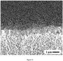
- the substrate usually comprises two distinct layers.
- the fine-grained thin top layer of a porous substrate usually exhibits pore sizes between about 1 to 1000 nm and supports the zeolite film, whereas the coarse-grained thick bottom or base layer has larger pores often in the micrometer range, such as 1 ⁇ m to 10 ⁇ m, such as 3 ⁇ m.
- the pore sizes of a substrate advantageously cause a low pressure drop while still providing mechanical stability to the membrane.
- Surface modification(s) of a substrate presented herein may be performed to any suitable porous substrate s.
- a "crystalline film” referred to herein is a crystalline structure characterized by exhibiting an X-ray diffraction pattern characteristic of the synthesized framework structure.
- a "hydrophobic surface” referred to herein is a substrate surface exhibiting a static contact angle of 90° or more at the three-phase contact line where a water droplet, substrate, and vapor phase meet.
- the term "monolayer" in the present context refers to a one crystal thick layer comprising discrete crystals, which are deposited on a substrate.
- the crystals and other materials if present may be closely packed to provide a classical monolayer. Alternatively the crystals and other materials if present are not closely packed and therefore are present as a sub-monolayer.
- the exact packing density required depends to a certain degree on the nature of the crystals and the desired film to be grown from these crystals.
- the packing density of crystals in the monolayer should in any event be such as to enable a thin layer of a zeolite film to be grown and intergrown from the crystals.
- the method as disclosed herein is not limited to deposition of only a monolayer, since films also can be grown from multilayers.
- amphiphile refers to a chemical compound which possesses both hydrophilic (polar) and lipophilic (unpolar) properties. Such a compound may also be referred to as an amphiphilic or amphipathic compound.
- a lipophilic group is typically a large hydrocarbon moiety, whereas a hydrophilic group falls into one of two groups; charged groups (anionic or cationic) or polar uncharged groups. Examples of amphiphiles suitable for use are further presented herein.
- the term "invasion” refers to unwanted depositon of material in the pores of the support.
- the material may be amorphous or crystalline material originating from the synthesis solution or originating from other sources.
- the seed crystals may grow into the pores of the support, which results in invasion of the support by crystalline material.
- the film should only coat the outermost part of the support and the pores of the support should be fully open, i.e. the invasion of the support shoud be minimal.
- a “masking procedure” as referred to herein, refers to a procedure wherein a substrate is treated to avoid invasion of crystals growing down in the pores of said substrate or ivasion of any species from the synthesis solution.
- dispersion refers to one or more compound(s), which are present in an aqueous or non-aqueous solution/mixture/dispersion.
- membrane and “film” as referred to herein, may be used interchangeably and refer to a barrier having separation properties, for separation of fluid mixtures such as mixtures of gases, liquids or mixtures thereof.
- nm stands for nanometer and mm stands for millimeter.
- a method for producing thin films comprising zeolites and/or zeolite-like crystals on a porous substrate wherein said film when synthesized on a porous substrate may be synthesized with minimal invasion and leaching of a porous substrate by rendering said substrate hydrophobic.
- This method comprises steps for pretreating substrates before the deposition and/or attachment of seed crystals thereon.
- the substrates which may also serve as a support for the film, may be substances with any porosity or are porous substrates with a well-defined and regular porosity as well as substrates with natural or synthetic porosity.
- Films as produced according to the method herein find use in the fields of membrane separation, sensor technology, catalysis, electrochemistry, ion exchange.
- a method for producing a crystalline film comprising zeolite and/or zeolite-like crystals on a porous substrate As defined in claim 1, the method comprises the steps of:
- the method comprises a step c) subsequent to step b) and prior to step d): c) treating the hydrophobic porous substrate obtained in step b) with a composition comprising one or more hydrophobicity adjusting agent(s), such as one or more amphiphile(s) and/or one or more ionic polymers.
- a composition comprising one or more hydrophobicity adjusting agent(s), such as one or more amphiphile(s) and/or one or more ionic polymers.
- amphiphiles and/or one or more ionic polymers may be as described herein.
- the one or more ionic polymer may be a cationic polymer.
- a thin film produced by a method provided herein refers to a film with a thickness of about less than 10 ⁇ m, such as less than about 1 ⁇ m, such as about 0.5 ⁇ m.
- the method as disclosed herein comprises a masking procedure, as said method aims at masking a porous substrate before zeolite and/or zeolite-like crystals are seeded and grown thereon to avoid invasion of the support by growth of zeolite and/or zeolite-crystals down into the pores of a porous substrate or invasion by species from the synthesis solution.
- An improved masking procedure implies shorter masking time and virtually no invasion of a porous substrate meaning that virtually no species from synthesis solution invades into the pores of the substrate and form an amorphous and/or crystalline phase, thereby substantially avoiding aforementioned drawbacks in the prior art.
- hydrophobic substrate which may be made hydrophobic throughout virtually all the substrate pores and up to the outermost surface of the substrate while keeping the substrate porous. Furthermore the method provided herein is fast and may easily be applied to supports with complex geometries.
- a substrate is masked and/or pretreated by rendering a porous substrate hydrophobic by treating said substrate with the one or more hydrophobic agent(s) recited in claim 1.
- a hydrophobic surface of said porous substrate is provided with zeolite and/or zeolite crystals (seed crystals), after one or more further surface modification(s) of said hydrophobic surface, and thereafter said crystals are allowed to grow on said hydrophobic surface or on said further modified hydrophobic surface to form a film.
- seed crystals zeolite and/or zeolite crystals
- said porous substrate When using the method as provided herein, and when using a porous substrate, said porous substrate will remain porous even after the substrate has been treated with one or more hydrophobicity adjusting agent(s). This is different from other methods used in the art, such as when a support is masked with wax. Further, close to the entire substrate material is protected, and especially the most critical part of the support material i.e. the upper part or top layer or outer surface of the material containing small pores which previously have been difficult to completely protect using prior masking methods. Without wishing to be bound by theory, this may be due to the fact that that it is more difficult for viscous fluids to enter very small pores than much larger pores and this difficulty should increase with decreasing pore size. Furthermore, the deposition of seed crystals on the hydrophobic substrate is different from previous methods known in the art, since the deposition presented herein relies on interactions between a hydrophobic substrate and hydrophilic or partly hydrophobic seed crystals.
- Preparation of hydrophobic surfaces may in principle be accomplished in two different ways; physically by optimizing the roughness of the substrate and chemically by deposition of hydrophobic molecules or entities onto the surface, or a combination of the two methods. It is well-known that fluorine in fluor-carbon compounds is efficient in lowering the surface free energy chemically because of its high electronegativity and accordingly strong covalent bonds with carbon atoms. ( Takashi Nishino et al., Langmuir 1999, 15, 4321-4323 ).
- the surface tension of most liquids decreases with increasing temperature in a nearly linear fashion and becomes very small in the region of the critical temperature, when the intermolecular cohesive forces approach zero.
- the surface tension of water is 72.72 mN/m at 20° C, but drops to 58.91 mN/m at 100° C [ Handbook of Chemistry and Physics, 71st Edition, 1990-1991, CRC Press, INC., ISBN: 0-8493-0471-7 ]. Consequently, the static contact angle between water and a substrate surface prepared according to a method as provided herein should be larger than 90°, preferably larger than 110° at 20°C, such as 125°. Such a high contact angle is facilitated by the roughness of the substrate surface. [ R. N. Wenzel, Ind. Eng. Chem. 1936, 28, 988-994 .]
- the method as provided herein is also simpler and cheaper to use than prior methods as all steps of said method may be carried out in e.g. a plastic beaker, e.g. no vacuum oven etc. is needed. Further, said method is fast and provides an attractive alternative within commercial timeframes.
- the masking through rendering a surface of said substrate hydrophobic may be performed in less than 1 h, as compared to masking using wax which usually require about 3 weeks.
- the method as provided herein is further well suited for substrate materials with a complex geometry, such as multi-channel tubes or honeycombs.
- ionic amphiphiles such as exemplified herein
- zeolite and/or zeolite-like crystals having an opposite charge to the surface sites formed after the attachment of said one or more amphiphile(s) to the hydrophobic surface, still keeping the surface hydrophobic.
- said amphiphile comprises a cation, to which thereafter negatively charged zeolite and/or zeolite-like crystals may attach.
- the surface charge of the substrate is not reversed from an initially negative to a positive value, as described in prior art such as for example in WO 97/33684 .
- a hydrophobic substrate provided by the method described herein is a prerequisite for seed crystals to remain attached to the substrate by hydrophobic interactions between the non-polar part of the amphiphiles and the hydrophobic substrate surface.
- the methods set forth in WO 97/33684 describe an initially negatively charged substrate surface and therefore a hydrophilic surface, which is charged reversed by treating the same surface with a cationic polymer.
- ionic amphiphiles to a hydrophobic surface of said substrate using hydrophobic interaction, followed by a further modification by providing one or more ionic polymer(s) to said amphiphilic surface to change the character of the ionic sites after the attachment of amphiphiles thereto, and thereafter in a suitable manner attach zeolite and/or zeolite-like crystals to this modified surface.
- ionic amphiphiles comprises an anion
- said amphiphilic surface is then provided with a cationic polymer to provide positively charged surface sites to which a negatively charged crystal may thereafter attach.
- Such modifications of the surface may be seen as a layer on layer principle, where the hydrophobic surface forms the bottom layer and wherein suitably additional surface modifications are provided for to attach the zeolite and/or zeolite-like crystals to a porous solid substrate.
- a surface modification method or pretreatment method as provided herein is particularly suitable for porous solid substrates.
- said J Z zeolite and/or zeolite-like crystals may be treated with one or more compositions comprising one or more amphiphile(s), e.g. by forming a dispersion comprising said crystals and one or more amphiphile(s), so that the crystals per se become at least partly hydrophobic by virtue of the treatment with said one or more amphiphiles, and wherein thereafter the formed at least partly hydrophobic crystals are directly attached onto a hydrophobic surface of a substrate as provided herein. Accordingly, said crystals are then attached to said substrate through hydrophobic interaction.
- one or more compositions comprising one or more amphiphile(s) e.g. by forming a dispersion comprising said crystals and one or more amphiphile(s), so that the crystals per se become at least partly hydrophobic by virtue of the treatment with said one or more amphiphiles, and wherein thereafter the formed at least partly hydrophobic crystals are directly attached onto a hydrophobic surface of a
- amphiphile and/or an ionic polymer which is provided to a surface herein, may be present in a dispersion which is suitable for the compound in question.
- the crystals may be referred to as seed crystals which are provided, usually in dispersion, to said porous substrate, either directly to said hydrophobic surface or to a further modified surface thereof, to form a layer, such as a monolayer, or multilayer of crystals thereon.
- the layer or monolayer comprising seed crystals is in a second step brought in contact with a synthesis mixture containing all the raw materials or starting materials needed for growth of the seed crystals to a film of the desired framework structure.
- the seeding and growth of the crystals occurs on a further modified surface of a porous substrate as presented herein.
- a layer or monolayer or multilayer of zeolite and/or zeolite crystals is formed, which may be seen as an intermediate product in the formation of the film.
- the layer or monolayer or multilayer is then allowed to grow into a film by hydrothermal treatment. Accordingly, an intermediate product is then comprised within the film.
- Growing crystals by hydrothermal treatment is a procedure known in the art.
- methods to provide said substrate with seed crystals known in prior art differs from the method provided herein.
- the zeolite and/or zeolite-like crystals used herein as seeds may refer to crystals with a length of less than 1000 nm, such as less than 500 nm, such as less than 200 nm, such as less than 100 nm, but is not limited thereto, the length of which can be identified by using Scanning Electron Microscopy.
- the crystals may be prepared by any suitable method known in the art, such as a method as disclosed in International Application PCT/SE93/00715 published as WO 94/05597 . This document describes a method whereby it is possible to synthesize colloidal suspensions of discrete molecular sieve microcrystals suitable for use in the preparation of monolayer structures.
- Molecular sieves such as zeolites or crystalline microporous metal silicates are generally synthesized by hydrothermal treatment of a silicate solution with a well-defined composition. This composition, as well as the synthesis parameters such as temperature, time and pressure, determines the type of product and the crystal shape obtained.
- Suitable seed crystals may be prepared in accordance with a method as presented in WO 93/08125 , or other methods known to those skilled in the art.
- molecular sieves zeolites
- zeolites include but are not limited to those of structure types AFI, AEL, BEA, CHA, EUO, FAU, FER, KFI, LTA, LTL, MAZ, MOR, MEL, MTN, MTT, DDR, MTW, OFF, TON (includes zeolite X and zeolite Y) zeolite beta, sodalite, ferrierite, phillipsite, and especially MFI zeolites.
- MFI zeolites with Si/AI ratios greater than 300 are herein referred to as silicalite.
- a starting material for producing seeds of zeolite and/or zeolite-like crystals and for subsequent growth of the seeds to a film may be selected from any compounds which is/are sufficiently reactive to produce a framework structure as previously mentioned herein.
- suitable silicon sources for producing a zeolite and/or zeolite-like crystal are for example silicon alkoxides, hydrated silicates, precipitated silica powders, fumed silica, and colloidal silica sols.
- Suitable aluminum sources are aluminium alkoxides, such as aluminium isopropoxide, aluminium metal, and aluminates.
- starting materials are monomeric forms of silicon such as tetraethyl orthosilicate and monomeric forms of aluminium such as aluminium isopropoxide.
- a synthesis mixture to form a zeolite and/or zeolite-like crystal is described in International Application WO93/08125 . In that process, a synthesis mixture is prepared by boiling an aqueous solution of a silica source and an organic structure directing agent in a proportion sufficient to cause substantially complete dissolution of the silica source.
- the organic structure directing agent if used, is advantageously introduced into the synthesis mixture in the form of a base, specifically in the form of a hydroxide, or in the form of a salt, e.g, a halide, especially a bromide.
- a base specifically in the form of a hydroxide
- a salt e.g, a halide, especially a bromide.
- Mixtures of a base and a salt thereof may be used, if desired or required, to adjust the pH of the mixture.
- Other methods for producing crystals are e.g. described in PCT/EP96/03096 , PCT/EP96/03097 , and PCT/EP96/0309698 .
- the zeolite and/or zeolite-like crystals may be produced by the hydroxide route or the fluoride route, or a combination thereof.
- Such methods are known in the art.
- the substrate is purified from possible contamination by washing with a suitable solvent such as acetone or a calcination procedure is performed.
- a suitable solvent such as acetone
- a calcination procedure is performed.
- the substrate e.g. ⁇ -Al 2 O 3
- the substrate is allowed to calcinate for about 6 h, where after it is cooled to room temperature. Heating and cooling takes about 6h, respectively. This procedure is performed so that any organic residues will be removed from the substrate and is a procedure which is used in the art.
- a surface of the substrate may be rendered hydrophobic in many different ways, such as by using the silanes (e.g. methoxy-, ethoxy, chloro-) with a perfluorated alkyl chain recited in claim 1 to thereby obtain a very hydrophobic substrate.
- the hydrophobic agent may be dissolved in a non-aqueous solvent such as ethanol, propanol or any other alcohol, and the low viscosity of the solution makes it possible for the solution to enter into all or at least most of the pores of the substrate, which is thereby rendered hydrophobic.
- a chemical modification of the surfaces of the substrate is performed by a method as provided herein, which is in sharp contrast to the previous methods known in the art relying on a simple pore filling by for instance wax.
- the hydrophobic and/or hydrophobicity adjusting agent may comprise one of more of the following: hydroxamate(s) and/or one or more silane coupling agent(s) such as alkyl silanes, fluorinated alkyl silanes, perfluorinated alkyl silanes, alkoxy silanes, hydro silanes, chloro silanes, or a combination thereof.
- silane coupling agent(s) such as alkyl silanes, fluorinated alkyl silanes, perfluorinated alkyl silanes, alkoxy silanes, hydro silanes, chloro silanes, or a combination thereof.
- the hydrophobic and/or hydrophobicity adjusting agent is selected from octylhydroxamate, decylhydroxamate, dodecylhydroxamate, octadecyltrihydrosilane, triethoxypropylsilane, 1H, 1H, 2H, 2H-perfluorodecyltriethoxysilane, 1H, 1H, 2H, 2H-perfluorodecyltrichlorosilane, trimethyloctylsilane, octyltrimethoxysilane, 1H, 1H, 2H, 2H-perfluorocetylmethyldichlorosilane, 1H, 1H, 2H, 2H-perfluorooctyltrimethoxysilane, or a combination thereof.
- the surface of the porous substrate is further modified.
- a further composition comprising one or more amphiphiles and/or a composition comprising one or more ionic polymers, is provided to the hydrophobic surface of a substrate, forming a second modified surface, which modified surface is thereafter used for attaching zeolite and/or zeolite-like crystals to the substrate.
- amphiphile attaches to the hydrophobic surface of said substrate by hydrophobic interaction. This is in sharp contrast the method described in patent WO97/33684 , where only electrostatic interactions are used and the surface is not hydrophobic. Accordingly, herein an amphiphile may be used in such a context wherein the hydrophobic part thereof will turn to a hydrophobic environment e.g. the hydrophobic substrate. Whether the amphiphile is anionic or cationic, the modified surface of the substrate will still be hydrophobic after this treatment. If the amphiphile is anionic, the surface may thereafter be treated with a cationic polymer to obtain surface sites with a positive charge to thereafter attach negatively charged zeolite and/or zeolite-like crystal seeds.
- compositions comprising one or more amphiphile(s) and a composition comprising one or more ionic polymers are used for the surface modification, these are deposited in separate subsequent steps meaning that said composition comprising one or more ionic polymer will attach to the newly formed surface comprising one or more amphiphile(s).
- a cationic polymer may have a repeat unit such as a quaternary amine with hydroxyl groups in the main chain.
- a repeat unit such as a quaternary amine with hydroxyl groups in the main chain.
- An example of such a polymer is poly(dimethylamine-co-epichlorhydrin-co-ethylenediamine with a repeat unit [CH 2 CH(OH)CH 2 N(CH 3 ) 2 ] n + and a molecular weight of 75,000 g/mol marketed by Sigma-Aldrich.
- Other suitable polymers are well known in the art.
- a cationic amphiphile may also be used thereby producing positively charged surface sites, which are possible to seed with negatively charged zeolite crystals. Thereby, it is not needed to provide a composition comprising one or more ionic polymer(s) to said substrate.
- methods provided herein are suitable to prepare substrates such as porous substrates for the deposition of a layer or a monolayer or multilayer of zeolite and/or zeolite-like crystals thereon from which a film or membrane will grow under hydrothermal crystallization conditions avoiding or at least minimizing invasion of the pores of a porous substrate.
- Invasion of dissolved species from synthesis solution or invasion by growth of zeolite crystals may result in a thicker film and hamper the gas or liquid permeation of the synthesized zeolite film/membrane and negatively affect its efficiency in applications, for example as adsorbent, membrane, or catalyst.
- the substrate may be exposed to a synthesis solution under hydrothermal treatment in for instance a Teflon bottle placed in an autoclave until an about 500 nm thick film is formed, which may require about 28 hours at 95° C for zeolite films based upon OH - as mineralizing agent. Because of said hydrophobicity of the porous substrate, the synthesis solution will not penetrate at all, or at least only to a limited extent penetrate into the pores of the porous substrate and accordingly little or no invasion of dissolved species from synthesis solution zeolite growth will occur.
- a method to prepare a layer or monolayer or multilayer structure comprising zeolite and/or zeolite-like crystals densely packed on the substrate surface.
- a dense layer of microcrystals deposited on a substrate surface is important for the growth and inter-growth of a membrane film at the substrate surface. If the microcrystals were deposited as a sparsely sub-monolayer, the growth and inter-growth of the zeolite film would provide a thicker zeolite film. A thicker zeolite film would impair the permeation of gas and liquid molecules through the membrane.
- the method as provided herein facilitates the synthesis of well-defined thin zeolite films on substrate surfaces with little or no invasion, which facilitates the control of the film thickness as well as the performance of the synthesized membrane in all possible applications, such as in selective separation processes, catalytic membrane reactors, chemical sensors, electrochemistry, and in the preparation of membranes from zeolite and zeolite-like crystals
- the synthesized crystalline zeolite film may be grown and inter-grown from zeolite and/or zeolite-like seed crystals forming a layer or monolayer or multilayer structure on the substrate surface using a synthesis method comprising; a) deposition of a monolayer or multilayer of zeolite or zeolite-like crystals on a substrate which crystals serves as nuclei for growth a film of zeolite and/or zeolite-like crystals, b) forming a zeolite and/or zeolite-like synthesis solution, c) contacting a) and b) and grow a zeolite film under hydrothermal conditions.
- a method for producing a crystalline film comprising zeolite and/or zeolite-like crystals on a substrate may also be referred to as a method for preparing a structure comprising a crystalline film comprising zeolite and/or zeolite-like crystals, wherein said structure produced by such a method comprises a substrate and zeolite and/or zeolite-like crystals.
- the substrate used is hydrophobic on any surface indirectly facing zeolite and/or zeolite-like crystals through a further surface modification of said hydrophobic surface of a porous or non-porous substrate. Still, all surface(s), or the entire surface, of a substrate as presented herein may not be hydrophobic, especially if a surface of a substrate is not used for seeding and growing crystals on.
- a substrate used in a method as provided herein may be selected from a group comprising or consisting of glass, sintered metals, metal alloys, steel, nickel, silicon, noble metals, carbon, polymers, inorganic oxides, alpha-alumina, gamma-alumina, titania, zirconia, silica, alumina/zirconia mixture(s), alumino silicates, cordierite, zeolite or zeolite-like materials, silicalite, zinc sulphide.
- a porous substrate may also be a fibrous material such as glass fibers, ceramic fibers, carbon fibers, graphite fibers, cellulose fibers, metal fibers, as well as various polymer fibers. All substrates may be produced by methods known in the art.
- a method as provided herein is well suited for substrate materials with a complex geometry, such as multi-channel tubes or honeycombs.
- a porous substrate may comprise pore sizes from the nanometer to the micrometer range, such as from 0.9 nm to 10 ⁇ m.
- the support may be multilayered; for example, to improve the mass transfer characteristics of the support, only the surface region of the support in contact with the layer or monolayer of seed crystals may have small diameter pores, while the bulk of the support, toward the surface remote from the layer, may have large diameter pores.
- nonporous substrates for coating with zeolite and/or zeolite-like films include solid silicon wafers, quartz, aliminium oxide, germanium, diamond, zinc sulphide, zinc selenide, zirconium dioxide, aluminium silicate and precious metals. Such substrates may be used in the field of sensor technology.
- Said zeolite and/or zeolite-like crystal may be selected from the group comprising silicalite, silicalite-1, zeolite A, zeolite Beta, the zeolites L, Y, X, ZSM-22, ZSM-11, ZSM-5, ZSM-2, LTA, SAPO-34, , DDR, mordenite, chabazite, sodalite, ferrierite and phillipsite but is not limited thereto. Further examples thereof are also provided herein.
- a zeolite and/or zeolite-like crystal may be silicalite-1.
- a hydrophobic substrate with a high contact angle is produced in order to assure that the porous substrate retains its hydrophobicity during the synthesis of the crystalline film from the layer of zeolite and/or zeolite-like crystals deposited on the substrate surface.
- Suitable chemicals to achieve high hydrophobicity of e.g. hydrophilic metal oxide substrates are the hydrophobic agents recited in claim 1.
- hydrophobic agent(s) or hydrophobicity adjusting agents when used for rendering a surface of a substrate hydrophobic.
- Said zeolite and/or zeolite-like crystals may be present in a dispersion when deposited and attached to a surface as presented in the above.
- this includes any kind of provision of the zeolite and/or zeolite-like zeolite crystals or the dispersion contacting them to the substrate in question such as by immersing, dipping or the like of a substrate in crystals or a dispersion containing crystals, or the pouring of a dispersion containing said crystals onto said substrate.
- a substrate such as a porous substrate may be fully or partly immersed or dipped into a solution or dispersion in a method provided herein.
- synthesis mixture, dispersion or the like is used interchangeably.
- a substrate such as a porous substrate is rendered hydrophobic in step b) said substrate may be calcined as previously described herein. Calcination is performed to remove any impurities from said substrate before it is treated in a method as provided herein. Calcination may also be performed at the end of the method.
- the method described herein may further comprise a step f) following step e): f) calcination.
- one or more amphiphile(s) may comprise an anion and/or a cation.
- Such one or more amphiphile(s) may be selected from the group comprising of alkyl ammonium ion(s) such as alkyl ammoniumfluoride, alkyl ammoniumchloride, and/or alkyl ammoniumbromide, salts of carboxylic acids, alkyl suphates, alkyl sulphonates, alkyl phospates, alkyl phosphonates or a combination thereof.
- Such one or more amphiphile(s) may also be selected from a group consisting of tetraalkyl ammonium ion(s) such as tetraalkyl ammoniumfluoride, tetraalkyl ammoniumchloride, and/or tetraalkyl ammoniumbromide, or a combination thereof.
- tetraalkyl ammonium ion(s) such as tetraalkyl ammoniumfluoride, tetraalkyl ammoniumchloride, and/or tetraalkyl ammoniumbromide, or a combination thereof.
- said ionic polymer may be a cationic polymer, such as polymers with various charge density and molecular weight.
- the growing in step e) may be performed by bringing a substrate comprising a layer of zeolite and/or zeolite-like crystals in contact with a synthesis solution, gel, or a dispersion, or the like comprising starting material(s) for preparing zeolites and/or zeolite-like crystals to produce the intended framework structure chemically, and any structure-directing agent needed for the synthesis. Thereafter, said zeolite and/or zeolite-like crystals are allowed to grow into a structure, e.g. a crystalline film as provided herein.
- step e said structure or film may be calcined to remove any organic molecules therefrom.
- said zeolite and/or zeolite-like crystals form a tightly packed and uniformly spread monolayer on the substrate surface.
- hydrothermal treatment of said crystals results in the growth of a thin zeolite film, with a thickness of for instance 500 nm on the substrate surface incorporating the (mono)layer of tightly packed zeolite crystals.
- an intergrown thin zeolite film firmly attached to a substrate via a layer or a monolayer of firmly attached zeolite crystals.
- a substrate such as a porous substrate used herein may also be referred to as a support material, despite forming a part of the product which is produced.
- the invention is further illustrated in the experimental section but is not intended to be limited thereto.
- said substrate Before a porous substrate is rendered hydrophobic in step b) said substrate may be calcined as previously described herein. Calcination is performed to remove any impurities from said substrate before it is treated in a method as provided herein.
- Step b) may further comprise the steps of:
- Step i) may be performed for about 0.1 to 5 hours, about 0.1 to 10 hours, or about 0.1 to 16 hours, such as for about 0.5, 1, 2, 3, 4, or 5 hours.
- Step ii) may be performed for about 0.5 to 3 hours, such as about 0.5 to 5 hours or about 0.5 to 10 hours, such as for about 0.5, 1, 2, 3, 4, or 5 hours.
- Rinsing is performed to remove substatially all of any non-reacting agents.
- Said solution may be an aqueous or non-aqueous solution.
- Step b) may further comprise the steps of:
- Step i) may be performed for about 0.1 to 5 hours, about 0.1 to 10 hours, or about 0.1 to 16 hours, such as for about 0.5, 1, 2, 3, 4, or 5 hours.
- Step ii) may be performed for about 0.5 to 3 hours, about 0.5 to 5 hours or about 0.5 to 10 hours.
- Said first hydrophobic agent may be the same or different from a second hydrophobic agent.
- Step a) and step b) of the method as disclosed herein may also be referred to as a method for producing a hydrophobic substrate or a masking method or procedure.
- a metod (step b) for producing a hydrophobic substrate or a masking method or procedure are provided in steps i) to iii) and i) to iv) herein.
- Said solution may be an alcohol, such as ethanol or propanol, but is not limited thereto.
- Example 1 (illustrative of steps a) and b))
- a circular disc of porous ⁇ -alumina(25 mm in diameter, 3 mm thick), provided with a 30 ⁇ m thick top layer of 100 nm pores and a 3 mm thick base layer with 3 ⁇ m pores was calcined in air at 500°C for 5 hours to remove any organic substances that might affect the interaction between ⁇ -aluminaand chemicals used in the subsequent steps.
- the substrate was immersed into a 2.5 weight per cent ethanol solution of 1H, 1H, 2H, 2H - perfluorodecyltriethoxysilane for 16 hours. Subsequently, the substrate was dipped into ethanol (99.9 %) and then placed in a beaker containing 99.9 % ethanol.
- the total time in ethanol was 5 hours and the ethanol was replaced by new ethanol every hour.
- the contact angle between a droplet (4 ⁇ L) of milliQ water and the substrate was measured with a FibroDat 1121/1122 system equipped with a CCD camera.
- the measured contact angle reached an equilibrium value after about 1 second of contact between the water droplet and the substrate.
- the value of the contact angle at equilibrium was larger than 125°, which implies that the surface modified substrate was hydrophobic.
- the contact angle of the calcined substrate, before surface modification was too low to be measured by the FibroDat system ( ⁇ 10°).
- the droplet was absorbed by the substrate.
- the substrate was exposed to an ethanol solution containing five weight per cent trimethoxyoctylsilane, for 30 minutes, rinsed with ethanol (99.9 %) for 10 minutes, and then exposed to a 5 weight per cent ethanol solution of of 1H, 1H, 2H, 2H - perfluoro cetylmethyldichlorosilane for 30 minutes and subsequently placed in a beaker containing -100 mL 99.9 % ethanol for 30 minutes.
- the contact angle between a droplet (4 ⁇ L) of milliQ water and the substrate was measured with a FibroDat 1121/1122 system equipped with a CCD camera. As shown in Figure 2 , the measured contact angle reached an equilibrium value after about 1 second of contact between the water droplet and the substrate. The contact angle at equilibrium was larger than 135°, whilst the contact angle of the calcined substrate was too low to be measured.
- the calcined substrate was surface modified using 1H, 1H, 2H, 2H - perfluoro decyltriethoxysilane by immersing the substrate in a solution containing 2.5 weight per cent of the carbonfluoro compound dissolved in ethanol. The immersion time was 1 hour. After keeping the substrate in 99.9 % ethanol for 8 hours, it was dried in a vacuum desiccator.
- the contact angle was measured with the FibroDat system described in Examples 1 and 2. The measured contact angle as function of time is shown in figure 3 .
- the calcined substrate was immersed in 2.5 weight per cent of 1H, 1H, 2H, 2H - perfluoro decyltriethoxysilane in ethanol as solvent.
- the immersion time was 1 hour.
- the substrate was dipped into 99.9 % ethanol and placed in a beaker with 100 mL ethanol (99.9 %) for 2 hours.
- the substrate was then dried for 60 minutes in an oven set to 60°C °C.
- the value of the equilibrium contact angle was larger than 125°, as shown in figure 4 .
- the surface of the porous substrate was made hydrophobic using 1H, 1H, 2H, 2H - perfluorodecyltriethoxysilane according to the method described in Example 1.
- the substrate was rinsed in 0.1 M aqueous ammonia solution and subsequently immersed in one weight per cent aqueous dispersion containing 1 wt.-% silicalite-1 crystals with an average diameter of about 50 nm. Deposition of the crystals onto the substrate surface was allowed to proceed for 10 minutes. After rinsing with 0.1 M aqueous ammonia, the substrate was calcined in air at 500°C for 3 hours. The monolayer deposition of the molecular sieve crystals onto the substrate surface was examined with Scanning Electron Microscopy (SEM) using a FEI Magellan 400 field emission instrument.
- SEM Scanning Electron Microscopy
- the sample was not coated in order to improve the conductivity before the SEM image was recorded.
- the substrate surface was covered with a monolayer of adsorbed silicalite-1 crystals except for a few very small spots where the crystals did not completely cover all parts of the surface.
- the substrate was made hydrophobic using a combination of trimethoxyloctylsilane and the fluorocarbon substance 1H, 1H, 2H, 2H - perfluorocetylmethyldichlorosilane, according to the method described in Example 2.
- the surface of the porous hydrophobic substrate was then further modified by immersing it for 20 minutes in 80 mM aqueous solution of decyltrimethylammonium bromide containing 5 weight per cent ethanol.
- the substrate was placed in a beaker with destilled water for 5 minutes and subsequently immersed in a 1 weight-percent aqueous dispersion containing silicalite-1 crystals with an average diameter of about 50 nm. Deposition of the crystals onto the substrate surface was allowed to proceed for 5 minutes. After rinsing with 0.1 M aqueous ammonia, the substrate was calcined in air at 500°C for 5 hours. The monolayer deposition of the molecular sieve crystals onto the substrate surface was examined with Scanning Electron Microscopy using a FEI Magellan 400 field emission instrument. The sample was not coated in order to improve the conductivity before the SEM image was recorded. As shown in Figure 6 , the substrate surface was covered with a monolayer of adsorbed silicalite-1 crystals.
- the substrate was made hydrophobic by immersing it in a 2.5 weigh percent ethanol solution of the fluorocarbon 1H, 1H, 2H, 2H - perfluorodecyltriethoxysilane according to the method described in Example 3.
- the surface of the porous hydrophobic substrate was now modified by immersing it for 20 minutes in 40 mM aqueous solution of decyltrimethylammonium bromide. The latter modification was preceded by dipping the substrate in ethanol (99.9 %) and letting the outermost part of the surface evaporate excess ethanol. The latter procedure improved the wetting properties of the hydrophobic surface.
- the substrate was rinsed with 0.01 M aqueous NH 3 solution and immersed in one weight-percent aqueous dispersion of silicalite-1 crystals with an average diameter of about 50 nm. Deposition of the crystals onto the substrate surface was allowed to proceed for 10 minutes. After rinsing with 0.01 M aqueous ammonia, the substrate was calcined in air at 500°C for 3 hours. The monolayer deposition of the molecular sieve crystals onto the substrate surface was examined with Scanning Electron Microscopy using a FEI Magellan 400 field emission instrument. The sample was not coated in order to improve the conductivity before the SEM image was recorded. As shown in Figure 7 , the substrate surface was covered with a monolayer of adsorbed silicalite-1 crystals.
- the substrate was made hydrophobic according to the method described in Example 3 and subsequently dipped into ethanol (99.9 %). After the ethanol had evaporated from the outermost part of the substrate surface, the substrate was immersed in one weight per cent silicalite-1 dispersion.
- the silicalite-1 dispersion was prepared by mixing 20 parts by volume of 5 weight per cent aqueous silicalite-1 dispersion with 70 parts by volume 0.1 M aqueous NH 3 and 10 parts by volume 40 mM aqueous decyltrimethylammonium bromide.
- the dispersion formed was allowed to equilibrate during 5 minutes with stirring and subsequently the substrate was brought in contact with the dispersion for 5 minutes. After rinsing with 0.01 M aqueous ammonia, the substrate was calcined in air at 500°C for 3 hours. The monolayer deposition of the molecular sieve crystals onto the substrate surface was examined with Scanning Electron Microscopy using a FEI Magellan 400 field emission instrument. The sample was not coated in order to improve the conductivity before the SEM image was recorded. As shown in Figure 8 , the substrate surface was covered with a monolayer of adsorbed silicalite-1crystals.
- the tube was provided with a 30 ⁇ m thick inner layer with100 nm pores and an outer layer with 3 ⁇ m pores.
- the tube was made hydrophobic according to Example 1, except that the immersion time in the ethanol solution containing 2.5 weight per cent 1H, 1H, 2H, 2H - perfluorodecyltriethoxysilane was 4 hours.
- a cationic polymer Poly(dimethylamine-co-epichlorhydrin-co-ethylenediamine) with an average molecular weight of 75000, from Aldrich
- the inner surface of the tube was rinsed with 0.1 M aqueous ammonia solution and subsequently treated with one weight per cent aqueous dispersion containing silicalite-1 crystals with an average diameter of about 50 nm. Deposition of the crystals onto the substrate surface was allowed to proceed for 10 minutes.
- FIG. 9 A representative Scanning Electron Microscopy image of the cross section of the calcined membrane is shown in Figure 9 . As illustrated by the Figure, the pores of the support are fully open and no invasion of the support has occured. No zeolite invasion of the support could be detected by recording numeros SEM images at various locations of the cross section , implying that synthesis solution could not penetrate through the hydrophobic barrier of the support.
- a porous ⁇ -alumina support as described in Example 1, was thoroughly rinsed with acetone, ethanol and 0.1 M aqueous ammonia to remove dust and any organic molecules attached to the surface of the substrate.
- the support was then treated by a masking procedure known in the art ( WO 00/53298 ) involving two steps; the first step implies that the top surface of the 100 nm pores was coated with a thin layer of poly (methyl methacrylate), in the second step the remainder of the support was filled with hydrocarbon wax.
- the entire poly (methyl methacrylate) was dissolved in acetone and the surface rinsed with 0.1 M aqueous NH 3 before the support was treated with 1 weight per cent aqueous cationic polymer (Poly(dimethylamine-co-epichlorhydrin-co-ethylenediamine) with an average molecular weight of 75000, from Aldrich) solution in order to reverse the charge of the support surface. Seeding of the support surface was accomplished by immersion of the support in 1 weight per cent silicalite-1 dispersion for 10 minutes. After seeding, the support was rinsed four times with 0.1 M aqueous NH 3 to remove excess seed crystals.
- 1 weight per cent aqueous cationic polymer Poly(dimethylamine-co-epichlorhydrin-co-ethylenediamine) with an average molecular weight of 75000, from Aldrich
- the seeded support was immersed in a synthesis solution with the composition: 25 SiO 2 : 3 TPAOH: 100 EtOH: 1500 H 2 O and hydrothermally treated in an oil bath at 100°C for 36 hours. After cooling, the sample was rinsed with 0.1 M aqueous NH 3 to remove loosely bound crystals and oligomers from the surface of the membrane.
- a representative Scanning Electron Microscopy image of the cross section of the calcined film is shown in Figure 10 . Invasion from the synthesis solution could be detected; implying that poly (methyl methacrylate) penetrated into the 100 nm pores or the hydrocarbon wax did not reach completely up to the poly (methyl methacrylate) coating. Invasion makes it difficult to optimize the thickness of the membrane and influences negatively the permeation through the membrane.
- the substrate was made hydrophobic according to the method described in Example 3 and subsequently dipped into ethanol (99.9 %).
- the substrate was then placed in a beaker containig about 50 mL ethanol for 1.5 hours. The ethanol was replaced once during this time.
- Ethanol was then evaporated from the substrate pores by drying in a vacuum desiccator for 2 hours.
- the top surface of the hydrophobic substrate was then further rinsed by immersing the substrate in a 0.001 M NaOH solution and placing this beaker in an oven set to 90°C for 1.5 hours.
- the substrate was subsequently dipped in water and then immersed in ethanol.
- a cationic polymer Eka ATC 4150, Eka Chemicals AB, Sweden
- the seeded substrate was then immmersed in a synthesis solution with the composition: 25 SiO 2 : 3 TPAOH: 100 EtOH: 1450 H 2 O and hydrothermally treated in an oil bath at 88°C for 71 hours.
- the thin-film composite anisotropic membrane was rinsed with 0.1 M aqueous ammonia to remove loosely bound crystals and oligomers from the surface of the membrane.
- the membrane was mounted in a stainless steel cell using graphite gaskets. Adsorbed components were then removed from the membrane by drying at 300°C in a flow of helium.
- the observed flux is as high as 635 kg m -2 h -1 at 21.5 °C and 550 kg m -2 h - 1 at 1.1°C at a feed pressure of 9 bar. These fluxes are much higher than for membranes masked with wax at comparable conditions [ Very high flux MFI membrane for CO2 separation, Sandström, L. , Sjöberg, E. & Hedlund, J. Journal of Membrane Science. 380, 232-240 (2011 )].
- the membrane is clearly selective towards carbon dioxide, with a separation factor of 14.5 at a feed pressure of 9 bar and a temperature of 1.1 °C.
- Example 12 (illustrative of steps a) and b))
- the calcined substrate was immersed in 34 mM ethanol solution of potassium dodecylhydroxamate for 1 hour. After this period of time, the substrate was rinsed with 99.7 % ethanol and placed in a beaker with 100 mL ethanol (99.7 %) for 1 hour. The substrate was then dried for 60 minutes in an oven set to 70 °C. The average value of the measured equilibrium contact angle was stable at 120° ⁇ 1°.
- the calcined substrate was surface modified using 1H, 1H, 2H, 2H - perfluoro decyltriethoxysilane by immersing the substrate in a solution containing 2.5 % by weight of the carbonfluoro compound dissolved in 99.7 % ethanol.
- the immersion time was 2 hours. After this immersion time, the substrate was rinsed with and then immersed in 99.7 % ethanol for 1 hour.
- the substrate was rinsed with filtered (0.1 ⁇ m) distilled water, immersed in 0.001 M acqueous solution of sodium hydroxide for 1 hour, rinsed with filtered distilled water, and finally with filtered 0.1 M ammonia solution.
- the substrate was immersed in filtered (0.8 ⁇ m) 1% by weight aqueous cationic polymer solution as hydrophobicity adjusting medium for 10 minutes followed by rinsing with filtered 0.1 M ammonia solution and immersion in filtered (0.2 ⁇ m) 1% by weight aqueous dispersion of silicalite-1 crystals for 10 minutes.
- the seeded substrate was rinsed with filtered 0.1 M ammonia solution and placed in a 60°C oven to dry.
- the deposition of the silicalite-1 crystals onto the substrate surface was examined with Scanning Electron Microscopy using a FEI Magellan 400 field emission instrument.
- the sample was not coated in order to improve the conductivity before the SEM image was recorded.
- the substrate surface was covered with a monolayer of silicalite-1 crystals with an average diameter of about 50 nm.
- the calcined substrate was surface modified using 1H, 1H, 2H, 2H - perfluoro decyltriethoxysilane by immersing the substrate in a solution containing filtered (0.1 ⁇ m) 2.5 % by weight of the carbonfluoro compound dissolved in 99.7 % ethanol. The immersion time was 1hour.
- the hydrophobic substrate was then rinsed with filtered (0.1 ⁇ m) ethanol, filtered (0.1 ⁇ m) distilled water and subsequently immersed in 0.001 M acqueous solution of sodium hydroxide for 1 hour.
- the substrate was rinsed with filtered distilled water, filtered 0.1 M ammonia solution, and then immersed in filtered (0.8 ⁇ m) 1 weight-percent acqueous cationic polymer solution for 10 minutes.
- the substrate was rinsed with filtered 0.1 M ammonia solution, dried on a laminar flow bench for an hour and a half and finally immersed in an filtered (0.45 ⁇ m) acqueous dispersion obtained by mixing a dispersion of 0.5 % by weight of FAU crystals with 32 % by weight acqueous tetrabutylammoniumbromide solution in the weight ratio 9:1.
- the immersion time was 10 minutes.
- the deposition of the FAU crystals onto the substrate surface was examined with Scanning Electron Microscopy using a FEI Magellan 400 field emission instrument.
- the sample was not coated in order to improve the conductivity before the SEM image was recorded.
- the substrate surface was covered with a monolayer of FAU crystals.
- a parallel sample was immersed in a synthesis solution with the composition: 80 Na 2 O: 1 Al 2 O 3 : 9 SiO 2 : 5000 H 2 O and treated hydrothermally in an oil bath at 100°C for 3 hours.
- a Scanning Electron Microscopy image of the cross section of the calcined zeolite-Y membrane showed a film thickness of about 700 nm, as shown in figure 13 ..
Description
- The present invention relates to the field of films of zeolites and zeolite-like crystals, more specifically to the pretreatment of porous substrates onto which films can be grown and the deposition of seed crystals on the substrates, which is an essential step for the preparation of thin films. These materials find use in the fields of membrane separation, sensor technology, catalysis, ion exchange, and electrochemistry.
- Zeolites and zeolite-like materials are microporous materials with well-defined pores up to 13 Å in diameter. Many molecules, whether in the gas or liquid phase, both inorganic and organic, have dimensions that fall within this range. Selecting a molecular sieve with a suitable pore size therefore allows separation of a molecule from a mixture based on the size of the molecule, which explains why zeolites and zeolite-like materials also are denoted "molecular sieves". In addition to this separation mechanism, where only molecules smaller than the pores of the molecular sieve can permeate, the pores within the material can separate molecular components having different adsorption and/or diffusion properties. Apart from the selective separation of uncharged species, the well-defined pore system of the molecular sieve enables selective ion exchange of charged species and selective catalysis. In the latter two cases, significant properties in addition to the micropore diameter are important, for instance, ion exchange capacity, specific surface area and acidity. Molecular sieves can be classified in various categories, for example according to their chemical composition and their structural properties. A group of molecular sieves of particular interest is the group comprising zeolites and zeolite-like materials.
- Zeolites and zeolite-like materials do not comprise an easily definable family of crystalline solids. However, the Structure Commission of the International Zeolite Association has presently approved more than 200 different zeolite framework types and assigned a 3-letter code to each framework. A criterion for distinguishing zeolites and zeolite-like materials from denser tectosilicates is based on the framework density, the number of tetrahedrally coordinated framework atoms per 1000 Å3. The tetrahedrally coordinated framework atoms are also denoted T-atoms. The maximum framework density for zeolites and zeolite-like materials ranges from 19 to over 21 tetrahedrally coordinated framework atoms per 1000 Å3, depending on the type of smallest ring present, whereas the minimum for denser structures ranges from 20 to 22. The Structure Commission maintains a zeolite structure database accessible via the internet [http://www.iza-structure.org/] and is also regularly revising and publishing the Atlas of Zeolite Framework Types. The 6th revised edition of the Atlas was published in 2007 [Ch. Baerlocher, L. B. Mc Cusker, D. H. Olson. Atlas of Zeolite Framework Types, 6th Ed., 2007, Elsevier, ISBN 978-0-444-53064-6]. Zeolite frameworks are built from TO4 tetrahedra and the T-atoms are usually silicon and aluminium atoms, but zeolite frameworks can also be prepared from only SiO4 thetrahedra. In the aluminophosphates (AlPO4), the T atoms are aluminium and phosphorous atoms. However, there are many more possibilities and atoms such as Si, Al, P, Ga, Ge, B, Be, Ti, Fe etc. can serve as T-atoms in zeolite frameworks.
- Zeolites and zeolite-like materials are microporous solids with a very regular pore structure of molecular dimensions. The dimensions of the channels control the maximum size of the molecular or ionic species that can enter the pores of a zeolite. The aperture of the channels are conventionally defined by the ring size, where, for example, the term "8-ring" refers to a closed loop that is built from 8 T-atoms and 8 oxygen atoms.
- Zeolites and zeolite like materials have a porous structure that can accommodate a wide variety of cations, such as Na+, K+, Ca2+, Mg2+ and others. These positive ions can readily be exchanged, which explains why zeolites can serve as ion exchangers.
- Natural zeolite minerals are usually formed where volcanic rocks and ash layers react with alkaline groundwater. Naturally occurring zeolites are rarely pure and are contaminated to varying degrees by other minerals, metals, quartz, or other zeolites. For this reason, naturally occurring zeolites are excluded from many important commercial applications where uniformity and purity are essential. Some of the more common zeolites found as minerals in nature are (3-letter codes within brackets) analcime (ANA), chabazite (CHA), clinoptilolite (HEU), heulandite (HEU), natrolite (NAT), phillipsite (PHI), and stilbite (STI).
- Zeolites and zeolite like materials can also be prepared synthetically. A frequently prepared zeolite framework is the MFI framework, which has 10 T-atoms in the ring and thereby a suitable pore size for many applications. This framework can be prepared in pure silica form, i.e. the T-atoms are only silicon atoms. In this case, the structure is denoted silicalite-1. However, if some of the silicon atoms are replaced with aluminium atoms, the structure is denoted ZSM-5. Templates or structure directing agents are added to the reaction mixture in the synthesis of zeolites and zeolite like materials to direct the crystallization to the desired framework. For example tetrapropyl ammonium hydroxide is often used as a template in the synthesis of MFI zeolite.
- There are numerous methods described in the art for the manufacture of substrate materials for inorganic catalysts and thin membranes, although there is still a need for improved substrate preparation, which is further explained herein. Substrates coated with thin films find their applications in for example the fields of membrane separation, sensor technology, catalysis, electrochemistry, ion exchange.
- When the film is prepared on a porous substrate using hydrothermal synthesis techniques, a number of problems may arise. Firstly, species from synthesis solution used for growth of zeolites and zeolite-like materials may invade and be deposited within the porous substrate, resulting in reduction of the porosity of the substrate implying reduced permeation of gas or liquid molecules through the complete structure. Secondly, the substrate material may not be inert under the synthesis conditions used resulting in dissolution of atoms from the substrate to an unacceptable degree, atoms that may interfere with the intended structure of the zeolite. Thirdly, in cases where calcination is preferred to remove a structure-directing agent from the synthesized film, the invaded and deposited species in the substrate may lead to crack formation in the film and the substrate due to differences in thermal expansion properties between the species and the substrate.
- Attempts to solve the first two problems have been described in the literature.
WO94/25151
Gavalas et al. describe the use of a specific barrier in zeolite membrane synthesis; "Use of diffusion barriers in the preparation of supported zeolite ZSM-5 membranes", Journal of Membrane Science, 126 (1997), 53-65. The authors describe a method implying that a mixture of furfuryl alcohol and tetraethylorthosilicate was impregnating a support. After impregnation, the mixture was polymerized by exposure to p-toluene sulfonic acid at elevated temperature and the resulting polymer was subsequently carbonized. Before the synthesis of the zeolite membrane, the carbonized polymer was removed from the top region of the support where the zeolite membrane was to be deposited. After synthesis of the zeolite membrane, all the carbon was removed by calcination. However, TEOS became converted to a silicate and deposited within the pores of the support not covered by carbon. - Thin continuous films of zeolite or zeolite-like crystals may be produced with techniques well known in the art. However, the preparation of the substrate upon which a continuous zeolite or zeolite-like film will be synthesized may vary. It is not always necessary to mask a porous substrate upon which a film of zeolite or zeolite-like crystals is grown. However, if masking of the substrate is preferred in order to prohibit the invasion of species from the synthesis solution into the substrate used as a support for the film, the masking procedure may involve filling the pores in the substrate with polymers or wax. Such a procedure is described in
WO 00/53298 WO 00/53298 WO 00/53298 - Another problem with the masking concept described above is the lack of control of the thickness of the synthesized membrane, since the invasion of species from synthesis solution may vary between different synthesized films/membranes as well as between different parts of the same film/membrane.
- A further problem associated with the masking concept described above and the partial invasion of the synthesis solution in the support is the fact that the conditions required for synthesizing numerous zeolite framework films are so severe that the substrate is partly dissolved or etched. Accordingly, aluminium may be dissolved from the top layer of a non-masked or incompletely masked α-alumina substrate leading to a zeolite structure that was not intended to be produced.
- A further problem with the masking concept described above is that it is difficult to apply to supports with complex geometries, such as multichannel tubes, needed to create large membrane surfaces for practical application of the membranes. Examples of commercially available multichannel alumina tubes are those sold by Inopor GmbH. Such tubes may for instance comprise 19 channels with a diameter of only 3.5 mm and a length of 1.2 m. It is straightforward to realize that it will be difficult to coat these narrow and long channels with PMMA perfectly as required for membrane preparation. Incomplete coating with PMMA would lead to protrusion of wax inside the channels, which would result in incomplete coverage of the channels with film and thereby defective membranes.
-
WO97/33684 - Accordingly, there is still a need in the art to produce films and membranes which avoid or minimizes the problems mentioned above, which are associated with known procedures for preparing films comprising zeolite and/or zeolite-like crystals on porous substrates. There is also a general need in the art to provide alternative measures for pretreatment of substrates or supports onto which subsequently seed crystals are to be deposited.
- The problems in the art have now been overcome or at least mitigated by the present invention by presenting a new method allowing to prepare thin films on porous or non-porous substrates which e.g. avoids invasion of a porous support, i.e. the deposition of material in the pores of the support, and which provides for an alternative and/or improved method of pretreating a support before deposition of seed crystals thereon. By making the porous support hydrophobic, the leaching of atoms from the support is minimized also at severe synthesis conditions where the substrate may otherwise be partly dissolved or etched and invasion is minimized.
- Accordingly, there is provided a method for producing a crystalline film comprising zeolite and/or zeolite-like crystals on a porous substrate, said method comprising the steps of:
- a) providing a porous substrate,
- b) rendering at least a part of said porous substrate hydrophobic by treatment with a composition comprising one or more hydrophobic agent(s) wherein the hydrophobic agent is selected from one or more of the following compounds: octylhydroxamate, decylhydroxamate, dodecylhydroxamate, octadecyltrihydrosilane, triethoxypropylsilane, 1H, 1H, 2H, 2H/perfluorodecyltriethoxysilane, 1H, 1H, 2H, 2H-perfluorodecyltrichlorosilane,trimethyloctylsilane, 1H, 1H, 2H, 2H- perfluorocetylmethyldichlorosilane, 1H, 1H,2H, 2H-perfluorooctyltrimethoxysilane, or a combination thereof,
- c) treating the hydrophobic porous substrate obtained in step b) with a composition comprising one or more amphiphile(s) and/or one or more ionic polymers,
- d) subjecting said treated porous substrate to a composition comprising zeolite and/or zeolite-like crystals thereby depositing and attaching zeolite and/or zeolite-like crystals on said treated porous substrate, and
- e) growing a crystalline film comprising zeolite and/or zeolite-like crystals on said treated porous substrate obtained in step d).
- A "zeolite and/or zeolite-like crystal" as prepared and referred to herein, may be a crystal of any of the framework types approved by the Structure Commission of the International Zeolite Association (http://www.iza-structure.org/). Such zeolites have the characteristics of large internal pore volume, molecular-size pores, regularity of crystal structure, and a diverse framework chemical composition making them highly active and selective catalysts, adsorbents, ion exchangers, and molecular sieves [J. D. Sherman. Proc Natl Acad Sci USA. 2000 May 23; 97(11); 6236.] The term crystal as referred to herein also refers to all synthetic crystals of zeolites and zeolite-like materials of any the framework types approved by the Structure Commission of the International Zeolite Association (http://www.iza-structure.org/). Representative of zeolite and/or zeolite-like crystals which may be produced by a method as disclosed herein include but are not limited to those of structure types AFI, AEL, BEA, CHA, EUO, FAU, FER, KFI, LTA, LTL, MAZ, MOR, MEL, MTN, MTT, MTW, OFF, TON, and especially MFI zeolites. Further examples falling within the above frameworks include silicalite, silicalite-1, TS-1, ZSM-5, and the zeolites sodalite, A, Beta, L, Y, X, ZSM-22, ZSM-11, ZSM-2, and SAPO-34. Some of the above materials, while not being true zeolites are frequently referred to in the literature as such, and the term zeolite will herein be used broadly to include such materials. Further, whenever a crystal, the crystals or the like is referred to herein, this is of course intended to refer also to a plurality of crystals of a framework type as defined herein. The crystals may also herein be referred to as microcrystals.
- A "substrate" as provided herein, is a porous substrate. A "porous substrate" is a substrate used as a support for producing crystalline films as presented herein, wherein said substrate comprises a certain porosity. The substrate usually comprises two distinct layers. The fine-grained thin top layer of a porous substrate usually exhibits pore sizes between about 1 to 1000 nm and supports the zeolite film, whereas the coarse-grained thick bottom or base layer has larger pores often in the micrometer range, such as 1µm to 10 µm, such as 3µm. The pore sizes of a substrate advantageously cause a low pressure drop while still providing mechanical stability to the membrane. Surface modification(s) of a substrate presented herein may be performed to any suitable porous substrate s.
- A "crystalline film" referred to herein, is a crystalline structure characterized by exhibiting an X-ray diffraction pattern characteristic of the synthesized framework structure.
- A "hydrophobic surface" referred to herein, is a substrate surface exhibiting a static contact angle of 90° or more at the three-phase contact line where a water droplet, substrate, and vapor phase meet.
- The term "monolayer" in the present context refers to a one crystal thick layer comprising discrete crystals, which are deposited on a substrate. The crystals and other materials if present may be closely packed to provide a classical monolayer. Alternatively the crystals and other materials if present are not closely packed and therefore are present as a sub-monolayer. The exact packing density required depends to a certain degree on the nature of the crystals and the desired film to be grown from these crystals. The packing density of crystals in the monolayer should in any event be such as to enable a thin layer of a zeolite film to be grown and intergrown from the crystals. However, the method as disclosed herein is not limited to deposition of only a monolayer, since films also can be grown from multilayers.
- An "amphiphile" refers to a chemical compound which possesses both hydrophilic (polar) and lipophilic (unpolar) properties. Such a compound may also be referred to as an amphiphilic or amphipathic compound. A lipophilic group is typically a large hydrocarbon moiety, whereas a hydrophilic group falls into one of two groups; charged groups (anionic or cationic) or polar uncharged groups. Examples of amphiphiles suitable for use are further presented herein.
- The term "invasion" refers to unwanted depositon of material in the pores of the support. The material may be amorphous or crystalline material originating from the synthesis solution or originating from other sources. The seed crystals may grow into the pores of the support, which results in invasion of the support by crystalline material. Ideally, the film should only coat the outermost part of the support and the pores of the support should be fully open, i.e. the invasion of the support shoud be minimal.
- A "masking procedure" as referred to herein, refers to a procedure wherein a substrate is treated to avoid invasion of crystals growing down in the pores of said substrate or ivasion of any species from the synthesis solution.
- Herein, the terms "dispersion", "solution" and "mixture" may be used interchangeably and refers to one or more compound(s), which are present in an aqueous or non-aqueous solution/mixture/dispersion.
- The terms "membrane" and "film" as referred to herein, may be used interchangeably and refer to a barrier having separation properties, for separation of fluid mixtures such as mixtures of gases, liquids or mixtures thereof.
- In this document, the terms "structure", "article" and "object" are used interchangeably.
- In this document, nm stands for nanometer and mm stands for millimeter.
-
-
Figure 1 . The time dependence of the contact angle between water and the porous α-alumina substrate according to Example 1. -
Figure 2 . The time dependence of the contact angle between water and the porous α-alumina substrate according to Example 2. -
Figure 3 . The time dependence of the contact angle between water and the porous α-alumina substrate according to Example 3. -
Figure 4 . The time dependence of the contact angle between water and the porous α-alumina substrate according to Example 4. -
Figure 5 . Scanning Electron Microscopy (SEM) image of silicalite-1 crystals forming a monolayer on a porous α-alumina substrate made hydrophobic according to Example 1. The method applied to deposit the monolayer onto the substrate was explained in Example 5.The cumulative average of the diameter of the silicalite-1 crystals was 51 nm. -
Figure 6 . SEM image of silicalite-1 crystals forming monolayer on a porous α-alumina substrate hydrophobized according to Example 2. The method applied to deposit the monolayer onto the substrate was explained in Example 6. The diameter of the silicalite-1 crystals was about 70 nm. -
Figure 7 . SEM image of silicalite-1 crystals forming monolayer on a porous α-alumina substrate made hydrophobic according to Example 3. The method applied to deposit the monolayer onto the substrate was explained in Example 7. The cumulative average of the diameter of the silicalite-1 crystals was 51 nm. -
Figure 8 . SEM image of silicalite-1 crystals forming monolayer on a porous α-alumina substrate made hydrophobic according to Example 3. The method applied to deposit the monolayer onto the substrate was explained in Example 8. The cumulative average of the diameter of the silicalite-1 crystals was 51 nm. -
Figure 9 . SEM image of a silicalite-1 membrane synthesized on the top layer of a porous α-aluminasubstrate made hydrophobic according to Example 1. A monolayer of silicalite-1 crystals was deposited according to the method explained in Example 5, before the membrane was synthesized according to the method described in Example 9. No support invasion was detected. -
Figure 10 . SEM image of a silicalite-1 membrane synthesized on the top layer of a porous α-aluminasubstrate according to a masking method well-known in the art (WO 00/53298 -
Figure 11 . SEM image of silicalite-1 crystals forming monolayer on a porous α-alumina substrate made hydrophobic according to Example 13. The method applied to deposit the monolayer onto the substrate was explained in Example 13. -
Figure 12 . SEM image of FAU crystals forming monolayer on a porous α-alumina substrate made hydrophobic according to Example 14. The method applied to deposit the monolayer onto the substrate was explained in Example 14. -
Figure 13 . SEM image of a zeolite-Y membrane synthesized on the top layer of a porous α-aluminasubstrate made hydrophobic and seeded according to Example 14. - There is provided herein a method for producing thin films comprising zeolites and/or zeolite-like crystals on a porous substrate wherein said film when synthesized on a porous substrate may be synthesized with minimal invasion and leaching of a porous substrate by rendering said substrate hydrophobic. This method comprises steps for pretreating substrates before the deposition and/or attachment of seed crystals thereon. The substrates, which may also serve as a support for the film, may be substances with any porosity or are porous substrates with a well-defined and regular porosity as well as substrates with natural or synthetic porosity. Films as produced according to the method herein find use in the fields of membrane separation, sensor technology, catalysis, electrochemistry, ion exchange.
- Accordingly, there is provided a method for producing a crystalline film comprising zeolite and/or zeolite-like crystals on a porous substrate As defined in
claim 1, the method comprises the steps of: - a) providing a porous substrate,
- b) rendering at least a part of said porous substrate hydrophobic by treatment with a composition comprising one or more hydrophobic agent(s),
- d) subjecting said treated porous substrate to a composition comprising zeolite and/or zeolite-like crystals thereby depositing and attaching zeolite and/or zeolite-like crystals on said treated porous substrate, and
- e) growing a crystalline film comprising zeolite and/or zeolite-like crystals on said treated porous substrate obtained in step d).
- The method comprises a step c) subsequent to step b) and prior to step d):
c) treating the hydrophobic porous substrate obtained in step b) with a composition comprising one or more hydrophobicity adjusting agent(s), such as one or more amphiphile(s) and/or one or more ionic polymers. - The amphiphiles and/or one or more ionic polymers may be as described herein. The one or more ionic polymer may be a cationic polymer.
- It is particularly useful to produce thin films with a controlled thickness and minimum invasion on porous substrates using a method as disclosed herein. A thin film produced by a method provided herein, refers to a film with a thickness of about less than 10 µm, such as less than about 1 µm, such as about 0.5 µm.
- The method as disclosed herein comprises a masking procedure, as said method aims at masking a porous substrate before zeolite and/or zeolite-like crystals are seeded and grown thereon to avoid invasion of the support by growth of zeolite and/or zeolite-crystals down into the pores of a porous substrate or invasion by species from the synthesis solution. An improved masking procedure implies shorter masking time and virtually no invasion of a porous substrate meaning that virtually no species from synthesis solution invades into the pores of the substrate and form an amorphous and/or crystalline phase, thereby substantially avoiding aforementioned drawbacks in the prior art. Hence, there is provided herein a hydrophobic substrate, which may be made hydrophobic throughout virtually all the substrate pores and up to the outermost surface of the substrate while keeping the substrate porous. Furthermore the method provided herein is fast and may easily be applied to supports with complex geometries.
- Accordingly, a substrate is masked and/or pretreated by rendering a porous substrate hydrophobic by treating said substrate with the one or more hydrophobic agent(s) recited in
claim 1. Thereafter, a hydrophobic surface of said porous substrate is provided with zeolite and/or zeolite crystals (seed crystals), after one or more further surface modification(s) of said hydrophobic surface, and thereafter said crystals are allowed to grow on said hydrophobic surface or on said further modified hydrophobic surface to form a film. The surface modifications are described in more detail herein, as well as the procedure for depositing the seed crystals onto said hydrophobic substrate. However, the procedure to grow a film from the seed crystals is well-known from prior art and is therefore only described briefly herein. - When using the method as provided herein, and when using a porous substrate, said porous substrate will remain porous even after the substrate has been treated with one or more hydrophobicity adjusting agent(s). This is different from other methods used in the art, such as when a support is masked with wax. Further, close to the entire substrate material is protected, and especially the most critical part of the support material i.e. the upper part or top layer or outer surface of the material containing small pores which previously have been difficult to completely protect using prior masking methods. Without wishing to be bound by theory, this may be due to the fact that that it is more difficult for viscous fluids to enter very small pores than much larger pores and this difficulty should increase with decreasing pore size. Furthermore, the deposition of seed crystals on the hydrophobic substrate is different from previous methods known in the art, since the deposition presented herein relies on interactions between a hydrophobic substrate and hydrophilic or partly hydrophobic seed crystals.
- Preparation of hydrophobic surfaces may in principle be accomplished in two different ways; physically by optimizing the roughness of the substrate and chemically by deposition of hydrophobic molecules or entities onto the surface, or a combination of the two methods. It is well-known that fluorine in fluor-carbon compounds is efficient in lowering the surface free energy chemically because of its high electronegativity and accordingly strong covalent bonds with carbon atoms. (Takashi Nishino et al., Langmuir 1999, 15, 4321-4323).
- It is well known that the surface tension of most liquids decreases with increasing temperature in a nearly linear fashion and becomes very small in the region of the critical temperature, when the intermolecular cohesive forces approach zero. The surface tension of water is 72.72 mN/m at 20° C, but drops to 58.91 mN/m at 100° C [Handbook of Chemistry and Physics, 71st Edition, 1990-1991, CRC Press, INC., ISBN: 0-8493-0471-7]. Consequently, the static contact angle between water and a substrate surface prepared according to a method as provided herein should be larger than 90°, preferably larger than 110° at 20°C, such as 125°. Such a high contact angle is facilitated by the roughness of the substrate surface. [R. N. Wenzel, Ind. Eng. Chem. 1936, 28, 988-994.]
- The method as provided herein is also simpler and cheaper to use than prior methods as all steps of said method may be carried out in e.g. a plastic beaker, e.g. no vacuum oven etc. is needed. Further, said method is fast and provides an attractive alternative within commercial timeframes.
- It further involves less work as its basis is only treating the substrate in different solutions. In addition, the masking through rendering a surface of said substrate hydrophobic may be performed in less than 1 h, as compared to masking using wax which usually require about 3 weeks. The method as provided herein is further well suited for substrate materials with a complex geometry, such as multi-channel tubes or honeycombs.
- As one alternative, it is possible to attach ionic amphiphiles, such as exemplified herein, directly to a hydrophobic surface of a substrate using hydrophobic interaction and thereafter attach zeolite and/or zeolite-like crystals having an opposite charge to the surface sites formed after the attachment of said one or more amphiphile(s) to the hydrophobic surface, still keeping the surface hydrophobic. This is for example suitable when said amphiphile comprises a cation, to which thereafter negatively charged zeolite and/or zeolite-like crystals may attach. By such a seeding alternative, the surface charge of the substrate is not reversed from an initially negative to a positive value, as described in prior art such as for example in
WO 97/33684 WO 97/33684 - It is also possible to e.g. attach ionic amphiphiles to a hydrophobic surface of said substrate using hydrophobic interaction, followed by a further modification by providing one or more ionic polymer(s) to said amphiphilic surface to change the character of the ionic sites after the attachment of amphiphiles thereto, and thereafter in a suitable manner attach zeolite and/or zeolite-like crystals to this modified surface. This is for example suitable when said amphiphile comprises an anion, and wherein said amphiphilic surface is then provided with a cationic polymer to provide positively charged surface sites to which a negatively charged crystal may thereafter attach.
- Such modifications of the surface may be seen as a layer on layer principle, where the hydrophobic surface forms the bottom layer and wherein suitably additional surface modifications are provided for to attach the zeolite and/or zeolite-like crystals to a porous solid substrate. A surface modification method or pretreatment method as provided herein is particularly suitable for porous solid substrates.
- In an alternate embodiment not according to the invention, said J Z zeolite and/or zeolite-like crystals may be treated with one or more compositions comprising one or more amphiphile(s), e.g. by forming a dispersion comprising said crystals and one or more amphiphile(s), so that the crystals per se become at least partly hydrophobic by virtue of the treatment with said one or more amphiphiles, and wherein thereafter the formed at least partly hydrophobic crystals are directly attached onto a hydrophobic surface of a substrate as provided herein. Accordingly, said crystals are then attached to said substrate through hydrophobic interaction.
- An amphiphile and/or an ionic polymer which is provided to a surface herein, may be present in a dispersion which is suitable for the compound in question.
- In the first step of the method of growing a crystalline film, the crystals may be referred to as seed crystals which are provided, usually in dispersion, to said porous substrate, either directly to said hydrophobic surface or to a further modified surface thereof, to form a layer, such as a monolayer, or multilayer of crystals thereon. The layer or monolayer comprising seed crystals is in a second step brought in contact with a synthesis mixture containing all the raw materials or starting materials needed for growth of the seed crystals to a film of the desired framework structure. The seeding and growth of the crystals occurs on a further modified surface of a porous substrate as presented herein. Hence, in a first step, a layer or monolayer or multilayer of zeolite and/or zeolite crystals is formed, which may be seen as an intermediate product in the formation of the film. The layer or monolayer or multilayer is then allowed to grow into a film by hydrothermal treatment. Accordingly, an intermediate product is then comprised within the film. Growing crystals by hydrothermal treatment is a procedure known in the art. However, methods to provide said substrate with seed crystals known in prior art differs from the method provided herein.
- The zeolite and/or zeolite-like crystals used herein as seeds may refer to crystals with a length of less than 1000 nm, such as less than 500 nm, such as less than 200 nm, such as less than 100 nm, but is not limited thereto, the length of which can be identified by using Scanning Electron Microscopy. The crystals may be prepared by any suitable method known in the art, such as a method as disclosed in International Application
PCT/SE93/00715 WO 94/05597 - Suitable seed crystals may be prepared in accordance with a method as presented in
WO 93/08125 - Further, a starting material for producing seeds of zeolite and/or zeolite-like crystals and for subsequent growth of the seeds to a film may be selected from any compounds which is/are sufficiently reactive to produce a framework structure as previously mentioned herein. Examples of suitable silicon sources for producing a zeolite and/or zeolite-like crystal are for example silicon alkoxides, hydrated silicates, precipitated silica powders, fumed silica, and colloidal silica sols. Suitable aluminum sources are aluminium alkoxides, such as aluminium isopropoxide, aluminium metal, and aluminates. Further examples of starting materials are monomeric forms of silicon such as tetraethyl orthosilicate and monomeric forms of aluminium such as aluminium isopropoxide. As an example, a synthesis mixture to form a zeolite and/or zeolite-like crystal is described in International Application
WO93/08125 PCT/EP96/03096 ,PCT/EP96/03097 , andPCT/EP96/0309698 - Accordingly, the zeolite and/or zeolite-like crystals may be produced by the hydroxide route or the fluoride route, or a combination thereof. Such methods are known in the art. Before the substrate is rendered hydrophobic, the substrate is purified from possible contamination by washing with a suitable solvent such as acetone or a calcination procedure is performed. During calcination the substrate, e.g. α-Al2O3, is slowly heated from room temperature to about 500°C. At such a temperature, the substrate is allowed to calcinate for about 6 h, where after it is cooled to room temperature. Heating and cooling takes about 6h, respectively. This procedure is performed so that any organic residues will be removed from the substrate and is a procedure which is used in the art.
- As mentioned in the above, a surface of the substrate may be rendered hydrophobic in many different ways, such as by using the silanes (e.g. methoxy-, ethoxy, chloro-) with a perfluorated alkyl chain recited in
claim 1 to thereby obtain a very hydrophobic substrate. The hydrophobic agent may be dissolved in a non-aqueous solvent such as ethanol, propanol or any other alcohol, and the low viscosity of the solution makes it possible for the solution to enter into all or at least most of the pores of the substrate, which is thereby rendered hydrophobic. - Accordingly, a chemical modification of the surfaces of the substrate is performed by a method as provided herein, which is in sharp contrast to the previous methods known in the art relying on a simple pore filling by for instance wax.
- The hydrophobic and/or hydrophobicity adjusting agent may comprise one of more of the following: hydroxamate(s) and/or one or more silane coupling agent(s) such as alkyl silanes, fluorinated alkyl silanes, perfluorinated alkyl silanes, alkoxy silanes, hydro silanes, chloro silanes, or a combination thereof.
- The hydrophobic and/or hydrophobicity adjusting agent is selected from octylhydroxamate, decylhydroxamate, dodecylhydroxamate, octadecyltrihydrosilane, triethoxypropylsilane, 1H, 1H, 2H, 2H-perfluorodecyltriethoxysilane, 1H, 1H, 2H, 2H-perfluorodecyltrichlorosilane, trimethyloctylsilane, octyltrimethoxysilane, 1H, 1H, 2H, 2H-perfluorocetylmethyldichlorosilane, 1H, 1H, 2H, 2H-perfluorooctyltrimethoxysilane, or a combination thereof.
- After the porous substrate has been rendered hydrophobic, or at least the part of the surface on which a crystalline film is to grow, the surface of the porous substrate is further modified. By such a procedure, the hydrophobic surface is still maintained but a further composition comprising one or more amphiphiles and/or a composition comprising one or more ionic polymers, is provided to the hydrophobic surface of a substrate, forming a second modified surface, which modified surface is thereafter used for attaching zeolite and/or zeolite-like crystals to the substrate.
- An amphiphile attaches to the hydrophobic surface of said substrate by hydrophobic interaction. This is in sharp contrast the method described in patent
WO97/33684 - A cationic polymer may have a repeat unit such as a quaternary amine with hydroxyl groups in the main chain. An example of such a polymer is poly(dimethylamine-co-epichlorhydrin-co-ethylenediamine with a repeat unit [CH2CH(OH)CH2N(CH3)2]n + and a molecular weight of 75,000 g/mol marketed by Sigma-Aldrich. Other suitable polymers are well known in the art.
- A cationic amphiphile may also be used thereby producing positively charged surface sites, which are possible to seed with negatively charged zeolite crystals. Thereby, it is not needed to provide a composition comprising one or more ionic polymer(s) to said substrate.
- Accordingly, methods provided herein are suitable to prepare substrates such as porous substrates for the deposition of a layer or a monolayer or multilayer of zeolite and/or zeolite-like crystals thereon from which a film or membrane will grow under hydrothermal crystallization conditions avoiding or at least minimizing invasion of the pores of a porous substrate. Invasion of dissolved species from synthesis solution or invasion by growth of zeolite crystals may result in a thicker film and hamper the gas or liquid permeation of the synthesized zeolite film/membrane and negatively affect its efficiency in applications, for example as adsorbent, membrane, or catalyst.
- As shown herein, for obtaining a zeolite film on a hydrophobic substrate with deposited microcrystals, the substrate may be exposed to a synthesis solution under hydrothermal treatment in for instance a Teflon bottle placed in an autoclave until an about 500 nm thick film is formed, which may require about 28 hours at 95° C for zeolite films based upon OH- as mineralizing agent. Because of said hydrophobicity of the porous substrate, the synthesis solution will not penetrate at all, or at least only to a limited extent penetrate into the pores of the porous substrate and accordingly little or no invasion of dissolved species from synthesis solution zeolite growth will occur.
- There is provided herein a method to prepare a layer or monolayer or multilayer structure comprising zeolite and/or zeolite-like crystals densely packed on the substrate surface. A dense layer of microcrystals deposited on a substrate surface is important for the growth and inter-growth of a membrane film at the substrate surface. If the microcrystals were deposited as a sparsely sub-monolayer, the growth and inter-growth of the zeolite film would provide a thicker zeolite film. A thicker zeolite film would impair the permeation of gas and liquid molecules through the membrane.
- The method as provided herein facilitates the synthesis of well-defined thin zeolite films on substrate surfaces with little or no invasion, which facilitates the control of the film thickness as well as the performance of the synthesized membrane in all possible applications, such as in selective separation processes, catalytic membrane reactors, chemical sensors, electrochemistry, and in the preparation of membranes from zeolite and zeolite-like crystals
- Thus, there is provided herein a method to prepare a substrate in such a way that hydrophobicity and/or masking of the substrate extends up to the outermost surface of the substrate, implying that e.g the invasion of species from solution is minimized when using a porous substrate. Hence, the synthesized crystalline zeolite film may be grown and inter-grown from zeolite and/or zeolite-like seed crystals forming a layer or monolayer or multilayer structure on the substrate surface using a synthesis method comprising; a) deposition of a monolayer or multilayer of zeolite or zeolite-like crystals on a substrate which crystals serves as nuclei for growth a film of zeolite and/or zeolite-like crystals, b) forming a zeolite and/or zeolite-like synthesis solution, c) contacting a) and b) and grow a zeolite film under hydrothermal conditions.
- A method for producing a crystalline film comprising zeolite and/or zeolite-like crystals on a substrate may also be referred to as a method for preparing a structure comprising a crystalline film comprising zeolite and/or zeolite-like crystals, wherein said structure produced by such a method comprises a substrate and zeolite and/or zeolite-like crystals.
- In a method as provided herein, the substrate used is hydrophobic on any surface indirectly facing zeolite and/or zeolite-like crystals through a further surface modification of said hydrophobic surface of a porous or non-porous substrate. Still, all surface(s), or the entire surface, of a substrate as presented herein may not be hydrophobic, especially if a surface of a substrate is not used for seeding and growing crystals on. Hence, when it is referred to "at least a part of a surface is rendered hydrophobic" or "rendering at least a part of said porous substrate hydrophobic", this still means that the part of the surface of a substrate to which a further surface modification is to be performed, fulfill the criteria for being hydrophobic and not allowing virtually any invasion of pores of a substrate, as previously defined herein. Hence, this may also be referred to as rendering the surface of a substrate, i.e. a porous or non-porous substrate hydrophobic, to which surface zeolite and/or zeolite-like crystals are to indirectly adhere. Examples of rendering a surface hydrophobic are provided in the experimental section.
- A substrate used in a method as provided herein may be selected from a group comprising or consisting of glass, sintered metals, metal alloys, steel, nickel, silicon, noble metals, carbon, polymers, inorganic oxides, alpha-alumina, gamma-alumina, titania, zirconia, silica, alumina/zirconia mixture(s), alumino silicates, cordierite, zeolite or zeolite-like materials, silicalite, zinc sulphide. A porous substrate may also be a fibrous material such as glass fibers, ceramic fibers, carbon fibers, graphite fibers, cellulose fibers, metal fibers, as well as various polymer fibers. All substrates may be produced by methods known in the art.
- An example of a porous substrate for use herein comprises circular discs of porous α-alumina (25 mm in diameter, 3 mm thick), comprising a 30 µm thick top layer of 100 nm pores and a 3 mm thick base layer with 3 µm pores. However, a method as provided herein is well suited for substrate materials with a complex geometry, such as multi-channel tubes or honeycombs.
- A porous substrate may comprise pore sizes from the nanometer to the micrometer range, such as from 0.9 nm to 10 µm. The support may be multilayered; for example, to improve the mass transfer characteristics of the support, only the surface region of the support in contact with the layer or monolayer of seed crystals may have small diameter pores, while the bulk of the support, toward the surface remote from the layer, may have large diameter pores.
- Examples of nonporous substrates for coating with zeolite and/or zeolite-like films include solid silicon wafers, quartz, aliminium oxide, germanium, diamond, zinc sulphide, zinc selenide, zirconium dioxide, aluminium silicate and precious metals. Such substrates may be used in the field of sensor technology.
- Said zeolite and/or zeolite-like crystal may be selected from the group comprising silicalite, silicalite-1, zeolite A, zeolite Beta, the zeolites L, Y, X, ZSM-22, ZSM-11, ZSM-5, ZSM-2, LTA, SAPO-34, , DDR, mordenite, chabazite, sodalite, ferrierite and phillipsite but is not limited thereto. Further examples thereof are also provided herein.
- A zeolite and/or zeolite-like crystal may be silicalite-1.
- A hydrophobic substrate with a high contact angle is produced in order to assure that the porous substrate retains its hydrophobicity during the synthesis of the crystalline film from the layer of zeolite and/or zeolite-like crystals deposited on the substrate surface. Suitable chemicals to achieve high hydrophobicity of e.g. hydrophilic metal oxide substrates are the hydrophobic agents recited in
claim 1. - Compounds or agents are referred to herein as hydrophobic agent(s) or hydrophobicity adjusting agents when used for rendering a surface of a substrate hydrophobic.
- Said zeolite and/or zeolite-like crystals may be present in a dispersion when deposited and attached to a surface as presented in the above. When deposited is referred to in the present context this includes any kind of provision of the zeolite and/or zeolite-like zeolite crystals or the dispersion contacting them to the substrate in question such as by immersing, dipping or the like of a substrate in crystals or a dispersion containing crystals, or the pouring of a dispersion containing said crystals onto said substrate. Further, a substrate such as a porous substrate may be fully or partly immersed or dipped into a solution or dispersion in a method provided herein. In the present context, synthesis mixture, dispersion or the like is used interchangeably.
- Before a substrate such as a porous substrate is rendered hydrophobic in step b) said substrate may be calcined as previously described herein. Calcination is performed to remove any impurities from said substrate before it is treated in a method as provided herein. Calcination may also be performed at the end of the method. Thus, the method described herein may further comprise a step f) following step e):
f) calcination. - In the method provided herein, one or more amphiphile(s) may comprise an anion and/or a cation. Such one or more amphiphile(s) may be selected from the group comprising of alkyl ammonium ion(s) such as alkyl ammoniumfluoride, alkyl ammoniumchloride, and/or alkyl ammoniumbromide, salts of carboxylic acids, alkyl suphates, alkyl sulphonates, alkyl phospates, alkyl phosphonates or a combination thereof. Such one or more amphiphile(s) may also be selected from a group consisting of tetraalkyl ammonium ion(s) such as tetraalkyl ammoniumfluoride, tetraalkyl ammoniumchloride, and/or tetraalkyl ammoniumbromide, or a combination thereof.
- In the method provided herein said ionic polymer may be a cationic polymer, such as polymers with various charge density and molecular weight.
- In the method as provided herein the growing in step e) may be performed by bringing a substrate comprising a layer of zeolite and/or zeolite-like crystals in contact with a synthesis solution, gel, or a dispersion, or the like comprising starting material(s) for preparing zeolites and/or zeolite-like crystals to produce the intended framework structure chemically, and any structure-directing agent needed for the synthesis. Thereafter, said zeolite and/or zeolite-like crystals are allowed to grow into a structure, e.g. a crystalline film as provided herein.
- Optionally, after step e) said structure or film may be calcined to remove any organic molecules therefrom.
- By a method as provided herein said zeolite and/or zeolite-like crystals form a tightly packed and uniformly spread monolayer on the substrate surface. However, it is also possible to deposit uniform multilayers on the surface.
- By a method as provided herein, hydrothermal treatment of said crystals results in the growth of a thin zeolite film, with a thickness of for
instance 500 nm on the substrate surface incorporating the (mono)layer of tightly packed zeolite crystals. - By a method as provided herein, there is provided an intergrown thin zeolite film firmly attached to a substrate via a layer or a monolayer of firmly attached zeolite crystals.
- A substrate such as a porous substrate used herein may also be referred to as a support material, despite forming a part of the product which is produced.
- The invention is further illustrated in the experimental section but is not intended to be limited thereto.
- Before a porous substrate is rendered hydrophobic in step b) said substrate may be calcined as previously described herein. Calcination is performed to remove any impurities from said substrate before it is treated in a method as provided herein.
- Step b) may further comprise the steps of:
- i) immersing said porous substrate in a solution comprising a hydrophobic agent recited in
claim 1, - ii) rinsing said substrate in a solution/solvent, and
- iii) drying said porous substrate.
- Step i) may be performed for about 0.1 to 5 hours, about 0.1 to 10 hours, or about 0.1 to 16 hours, such as for about 0.5, 1, 2, 3, 4, or 5 hours.
- Step ii) may be performed for about 0.5 to 3 hours, such as about 0.5 to 5 hours or about 0.5 to 10 hours, such as for about 0.5, 1, 2, 3, 4, or 5 hours.
- Rinsing is performed to remove substatially all of any non-reacting agents.
- Said solution may be an aqueous or non-aqueous solution.
- Step b) may further comprise the steps of:
- i) immersing said porous substrate in a solution comprising a first hydrophobic agent recited in
claim 1, - ii) rinsing said substrate in a solution/solvent,
- iii) immersing said porous substrate in a solution comprising a second hydrophobic agent recited in
claim 1, and - iv) rinsing and/or maintaining said porous substrate in a solvent/solution.
- Step i) may be performed for about 0.1 to 5 hours, about 0.1 to 10 hours, or about 0.1 to 16 hours, such as for about 0.5, 1, 2, 3, 4, or 5 hours.
- Step ii) may be performed for about 0.5 to 3 hours, about 0.5 to 5 hours or about 0.5 to 10 hours.
- Said first hydrophobic agent may be the same or different from a second hydrophobic agent.
- Step a) and step b) of the method as disclosed herein, may also be referred to as a method for producing a hydrophobic substrate or a masking method or procedure. Examples of such a metod (step b) for producing a hydrophobic substrate or a masking method or procedure are provided in steps i) to iii) and i) to iv) herein.
- Said solution may be an alcohol, such as ethanol or propanol, but is not limited thereto.
- A circular disc of porous α-alumina(25 mm in diameter, 3 mm thick), provided with a 30 µm thick top layer of 100 nm pores and a 3 mm thick base layer with 3 µm pores was calcined in air at 500°C for 5 hours to remove any organic substances that might affect the interaction between α-aluminaand chemicals used in the subsequent steps. The substrate was immersed into a 2.5 weight per cent ethanol solution of 1H, 1H, 2H, 2H - perfluorodecyltriethoxysilane for 16 hours. Subsequently, the substrate was dipped into ethanol (99.9 %) and then placed in a beaker containing 99.9 % ethanol. The total time in ethanol was 5 hours and the ethanol was replaced by new ethanol every hour. After drying for 1 hour at 105°C, the contact angle between a droplet (4 µL) of milliQ water and the substrate was measured with a FibroDat 1121/1122 system equipped with a CCD camera. As shown in
Figure 1 , the measured contact angle reached an equilibrium value after about 1 second of contact between the water droplet and the substrate. The value of the contact angle at equilibrium was larger than 125°, which implies that the surface modified substrate was hydrophobic. The contact angle of the calcined substrate, before surface modification, was too low to be measured by the FibroDat system (<10°). The droplet was absorbed by the substrate. - A porous α-aluminasubstrate, as described in Example 1, was calcined in air at 500°C for 5 hours. The substrate was exposed to an ethanol solution containing five weight per cent trimethoxyoctylsilane, for 30 minutes, rinsed with ethanol (99.9 %) for 10 minutes, and then exposed to a 5 weight per cent ethanol solution of of 1H, 1H, 2H, 2H - perfluoro cetylmethyldichlorosilane for 30 minutes and subsequently placed in a beaker containing -100 mL 99.9 % ethanol for 30 minutes. After drying for 1 hour at 105°C, the contact angle between a droplet (4 µL) of milliQ water and the substrate was measured with a FibroDat 1121/1122 system equipped with a CCD camera. As shown in
Figure 2 , the measured contact angle reached an equilibrium value after about 1 second of contact between the water droplet and the substrate. The contact angle at equilibrium was larger than 135°, whilst the contact angle of the calcined substrate was too low to be measured. - A porous α-aluminasubstrate, as described in Example 1, was calcined in air at 500°C for 5 hours. The calcined substrate was surface modified using 1H, 1H, 2H, 2H - perfluoro decyltriethoxysilane by immersing the substrate in a solution containing 2.5 weight per cent of the carbonfluoro compound dissolved in ethanol. The immersion time was 1 hour. After keeping the substrate in 99.9 % ethanol for 8 hours, it was dried in a vacuum desiccator. The contact angle was measured with the FibroDat system described in Examples 1 and 2. The measured contact angle as function of time is shown in
figure 3 . - A porous α-aluminasubstrate, as described in Example 1, was calcined in air at 500°C for 5 hours. The calcined substrate was immersed in 2.5 weight per cent of 1H, 1H, 2H, 2H - perfluoro decyltriethoxysilane in ethanol as solvent. The immersion time was 1 hour. After this period of time, the substrate was dipped into 99.9 % ethanol and placed in a beaker with 100 mL ethanol (99.9 %) for 2 hours. The substrate was then dried for 60 minutes in an oven set to 60°C °C. The value of the equilibrium contact angle was larger than 125°, as shown in
figure 4 . - A porous α-aluminasubstrate, as described in Example 1, was calcined in air at 500°C for 5 hours. The surface of the porous substrate was made hydrophobic using 1H, 1H, 2H, 2H - perfluorodecyltriethoxysilane according to the method described in Example 1. The hydrophobic substrate was immersed in a solution containing one weight per cent of a cationic polymer (Poly(dimethylamine-co-epichlorhydrin-co-ethylenediamine) with an average molecular weight of 75000, from Aldrich) dissolved in aqueous ammonia (pH = 10). After 10 minutes in the aqueous polymer solution, the substrate was rinsed in 0.1 M aqueous ammonia solution and subsequently immersed in one weight per cent aqueous dispersion containing 1 wt.-% silicalite-1 crystals with an average diameter of about 50 nm. Deposition of the crystals onto the substrate surface was allowed to proceed for 10 minutes. After rinsing with 0.1 M aqueous ammonia, the substrate was calcined in air at 500°C for 3 hours. The monolayer deposition of the molecular sieve crystals onto the substrate surface was examined with Scanning Electron Microscopy (SEM) using a
FEI Magellan 400 field emission instrument. The sample was not coated in order to improve the conductivity before the SEM image was recorded. As shown inFigure 5 , the substrate surface was covered with a monolayer of adsorbed silicalite-1 crystals except for a few very small spots where the crystals did not completely cover all parts of the surface. - A porous α-aluminasubstrate, described in Example 1, was calcined in air at 500°C for 5 hours. The substrate was made hydrophobic using a combination of trimethoxyloctylsilane and the fluorocarbon substance 1H, 1H, 2H, 2H - perfluorocetylmethyldichlorosilane, according to the method described in Example 2. The surface of the porous hydrophobic substrate was then further modified by immersing it for 20 minutes in 80 mM aqueous solution of decyltrimethylammonium bromide containing 5 weight per cent ethanol. After surface modification with the ammonium bromide, the substrate was placed in a beaker with destilled water for 5 minutes and subsequently immersed in a 1 weight-percent aqueous dispersion containing silicalite-1 crystals with an average diameter of about 50 nm. Deposition of the crystals onto the substrate surface was allowed to proceed for 5 minutes. After rinsing with 0.1 M aqueous ammonia, the substrate was calcined in air at 500°C for 5 hours. The monolayer deposition of the molecular sieve crystals onto the substrate surface was examined with Scanning Electron Microscopy using a
FEI Magellan 400 field emission instrument. The sample was not coated in order to improve the conductivity before the SEM image was recorded. As shown inFigure 6 , the substrate surface was covered with a monolayer of adsorbed silicalite-1 crystals. - A porous α-aluminasubstrate, described in Example 1, was calcined in air at 500°C for 5 hours. The substrate was made hydrophobic by immersing it in a 2.5 weigh percent ethanol solution of the fluorocarbon 1H, 1H, 2H, 2H - perfluorodecyltriethoxysilane according to the method described in Example 3. The surface of the porous hydrophobic substrate was now modified by immersing it for 20 minutes in 40 mM aqueous solution of decyltrimethylammonium bromide. The latter modification was preceded by dipping the substrate in ethanol (99.9 %) and letting the outermost part of the surface evaporate excess ethanol. The latter procedure improved the wetting properties of the hydrophobic surface. After treatment with the quaternary ammonium solution, the substrate was rinsed with 0.01 M aqueous NH3 solution and immersed in one weight-percent aqueous dispersion of silicalite-1 crystals with an average diameter of about 50 nm. Deposition of the crystals onto the substrate surface was allowed to proceed for 10 minutes. After rinsing with 0.01 M aqueous ammonia, the substrate was calcined in air at 500°C for 3 hours. The monolayer deposition of the molecular sieve crystals onto the substrate surface was examined with Scanning Electron Microscopy using a
FEI Magellan 400 field emission instrument. The sample was not coated in order to improve the conductivity before the SEM image was recorded. As shown inFigure 7 , the substrate surface was covered with a monolayer of adsorbed silicalite-1 crystals. - A porous α-alumina substrate, described in Example 1, was calcined in air at 500°C for 5 hours. The substrate was made hydrophobic according to the method described in Example 3 and subsequently dipped into ethanol (99.9 %). After the ethanol had evaporated from the outermost part of the substrate surface, the substrate was immersed in one weight per cent silicalite-1 dispersion. The silicalite-1 dispersion was prepared by mixing 20 parts by volume of 5 weight per cent aqueous silicalite-1 dispersion with 70 parts by volume 0.1 M aqueous NH3 and 10 parts by volume 40 mM aqueous decyltrimethylammonium bromide. The dispersion formed was allowed to equilibrate during 5 minutes with stirring and subsequently the substrate was brought in contact with the dispersion for 5 minutes. After rinsing with 0.01 M aqueous ammonia, the substrate was calcined in air at 500°C for 3 hours. The monolayer deposition of the molecular sieve crystals onto the substrate surface was examined with Scanning Electron Microscopy using a
FEI Magellan 400 field emission instrument. The sample was not coated in order to improve the conductivity before the SEM image was recorded. As shown inFigure 8 , the substrate surface was covered with a monolayer of adsorbed silicalite-1crystals. - A porous α-alumina tube with geometry; L = 100 mm, Douter = 10 mm, and Dinner = 7 mm, was calcined in air at 500° C. The tube was provided with a 30 µm thick inner layer with100 nm pores and an outer layer with 3 µm pores. The tube was made hydrophobic according to Example 1, except that the immersion time in the ethanol solution containing 2.5 weight per cent 1H, 1H, 2H, 2H - perfluorodecyltriethoxysilane was 4 hours. After drying, the inner surface of the hydrophobic tube was treated with a solution containing one weight per cent of a cationic polymer (Poly(dimethylamine-co-epichlorhydrin-co-ethylenediamine) with an average molecular weight of 75000, from Aldrich) dissolved in aqueous ammonia (pH = 11). After 10 minutes in the aqueous polymer solution, the inner surface of the tube was rinsed with 0.1 M aqueous ammonia solution and subsequently treated with one weight per cent aqueous dispersion containing silicalite-1 crystals with an average diameter of about 50 nm. Deposition of the crystals onto the substrate surface was allowed to proceed for 10 minutes. After rinsing with 0.1 M aqueous ammonia, the support was immersed in synthesis solution with the molar composition: 50 SiO2: 6 TPAOH: 1 Na2O: 3000 H2O. The silicalite-1 film was grown by hydrothermal treatment at 95°C for 28 hours. After cooling, the sample was rinsed with 0.1 M aqueous NH3 to remove loosely bound crystals and oligomers from the surface of the membrane. A representative Scanning Electron Microscopy image of the cross section of the calcined membrane is shown in
Figure 9 . As illustrated by the Figure, the pores of the support are fully open and no invasion of the support has occured. No zeolite invasion of the support could be detected by recording numeros SEM images at various locations of the cross section , implying that synthesis solution could not penetrate through the hydrophobic barrier of the support. - A porous α-alumina support, as described in Example 1, was thoroughly rinsed with acetone, ethanol and 0.1 M aqueous ammonia to remove dust and any organic molecules attached to the surface of the substrate. The support was then treated by a masking procedure known in the art (
WO 00/53298 Figure 10 . Invasion from the synthesis solution could be detected; implying that poly (methyl methacrylate) penetrated into the 100 nm pores or the hydrocarbon wax did not reach completely up to the poly (methyl methacrylate) coating. Invasion makes it difficult to optimize the thickness of the membrane and influences negatively the permeation through the membrane. - A porous α-alumina substrate, described in Example 1, was calcined in air at 500°C for 5 hours. The substrate was made hydrophobic according to the method described in Example 3 and subsequently dipped into ethanol (99.9 %). The substrate was then placed in a beaker containig about 50 mL ethanol for 1.5 hours. The ethanol was replaced once during this time. Ethanol was then evaporated from the substrate pores by drying in a vacuum desiccator for 2 hours. The top surface of the hydrophobic substrate was then further rinsed by immersing the substrate in a 0.001 M NaOH solution and placing this beaker in an oven set to 90°C for 1.5 hours. The substrate was subsequently dipped in water and then immersed in ethanol. After this, the substrate was immersed in a solution containing one weight per cent of a cationic polymer (Eka ATC 4150, Eka Chemicals AB, Sweden) dissolved in aqueous ammonia (pH = 10). After 10 minutes in the aqueous polymer solution, the substrate was rinsed with 0.1 M aqueous ammonia solution and subsequently treated with one weight per cent aqueous dispersion containing silicalite-1 crystals with an average diameter of about 50 nm. Deposition of the crystals onto the substrate surface was allowed to proceed for 10 minutes. After rinsing with 0.1 M aqueous ammonia, the substrate was left to dry over night. The seeded substrate was then immmersed in a synthesis solution with the composition: 25 SiO2: 3 TPAOH: 100 EtOH: 1450 H2O and hydrothermally treated in an oil bath at 88°C for 71 hours. After cooling, the thin-film composite anisotropic membrane was rinsed with 0.1 M aqueous ammonia to remove loosely bound crystals and oligomers from the surface of the membrane. After calcination at 500°C, the membrane was mounted in a stainless steel cell using graphite gaskets. Adsorbed components were then removed from the membrane by drying at 300°C in a flow of helium. After cooling to room temperature, an equimolar mixture of hydrogen and carbon dioxide with a total flow rate of 15 NL/min was fed to the membrane at varying feed pressures. The composition of the permeate stream was analyzed using a mass spectrometer (InProcess Instruments GmbH, GAM 400). The pressure of the permeate stream was atmoshperic, and the gas flow of the permeate stream was measured using a drum-type gas meter (Ritter Apparatebau GmbH). The separation properties of the membrane were investigated at two membrane temperatures; 21.5°C and 1.1 °C. Due to a low film thickness and a low amount of support invasion, the observed flux is as high as 635 kg m-2 h-1 at 21.5 °C and 550 kg m-2
h -1 at 1.1°C at a feed pressure of 9 bar. These fluxes are much higher than for membranes masked with wax at comparable conditions [Very high flux MFI membrane for CO2 separation, Sandström, L. , Sjöberg, E. & Hedlund, J. Journal of Membrane Science. 380, 232-240 (2011)]. The observed carbon dioxide/hydrogen separation factor, α, is defined as α = (yi/yj) / (xi/xj), where yi is the molar fraction of component i in the permeate stream and xi is the molar fraction of component i in the calculated average of the feed and retentate streams. The membrane is clearly selective towards carbon dioxide, with a separation factor of 14.5 at a feed pressure of 9 bar and a temperature of 1.1 °C. - A porous α-alumina substrate, as described in Example 1, was calcined in air at 500°C for 5 hours. The calcined substrate was immersed in 34 mM ethanol solution of potassium dodecylhydroxamate for 1 hour. After this period of time, the substrate was rinsed with 99.7 % ethanol and placed in a beaker with 100 mL ethanol (99.7 %) for 1 hour. The substrate was then dried for 60 minutes in an oven set to 70 °C. The average value of the measured equilibrium contact angle was stable at 120° ± 1°.
- A porous α-alumina substrate, as described in Example 1, was calcined in air at 500°C for 6 hours. The calcined substrate was surface modified using 1H, 1H, 2H, 2H - perfluoro decyltriethoxysilane by immersing the substrate in a solution containing 2.5 % by weight of the carbonfluoro compound dissolved in 99.7 % ethanol. The immersion time was 2 hours. After this immersion time, the substrate was rinsed with and then immersed in 99.7 % ethanol for 1 hour. Subsequently, the substrate was rinsed with filtered (0.1 µm) distilled water, immersed in 0.001 M acqueous solution of sodium hydroxide for 1 hour, rinsed with filtered distilled water, and finally with filtered 0.1 M ammonia solution. After this treatment, the substrate was immersed in filtered (0.8 µm) 1% by weight aqueous cationic polymer solution as hydrophobicity adjusting medium for 10 minutes followed by rinsing with filtered 0.1 M ammonia solution and immersion in filtered (0.2 µm) 1% by weight aqueous dispersion of silicalite-1 crystals for 10 minutes. The seeded substrate was rinsed with filtered 0.1 M ammonia solution and placed in a 60°C oven to dry. The deposition of the silicalite-1 crystals onto the substrate surface was examined with Scanning Electron Microscopy using a
FEI Magellan 400 field emission instrument. The sample was not coated in order to improve the conductivity before the SEM image was recorded. As shown inFigure 11 , the substrate surface was covered with a monolayer of silicalite-1 crystals with an average diameter of about 50 nm. - A porous α-alumina substrate, as described in Example 1, was calcined in air at 500°C for 6 hours. The calcined substrate was surface modified using 1H, 1H, 2H, 2H - perfluoro decyltriethoxysilane by immersing the substrate in a solution containing filtered (0.1 µm) 2.5 % by weight of the carbonfluoro compound dissolved in 99.7 % ethanol. The immersion time was 1hour. The hydrophobic substrate was then rinsed with filtered (0.1 µm) ethanol, filtered (0.1 µm) distilled water and subsequently immersed in 0.001 M acqueous solution of sodium hydroxide for 1 hour. Subsequently, the substrate was rinsed with filtered distilled water, filtered 0.1 M ammonia solution, and then immersed in filtered (0.8 µm) 1 weight-percent acqueous cationic polymer solution for 10 minutes. After this treatment, the substrate was rinsed with filtered 0.1 M ammonia solution, dried on a laminar flow bench for an hour and a half and finally immersed in an filtered (0.45 µm) acqueous dispersion obtained by mixing a dispersion of 0.5 % by weight of FAU crystals with 32 % by weight acqueous tetrabutylammoniumbromide solution in the weight ratio 9:1. The immersion time was 10 minutes. After the substrate was rinsed with filtered 0.1 M ammonia solution and dried in a 60°C oven, the deposition of the FAU crystals onto the substrate surface was examined with Scanning Electron Microscopy using a
FEI Magellan 400 field emission instrument. The sample was not coated in order to improve the conductivity before the SEM image was recorded. As shown inFigure 12 , the substrate surface was covered with a monolayer of FAU crystals. Subsequently, a parallel sample was immersed in a synthesis solution with the composition: 80 Na2O: 1 Al2O3: 9 SiO2: 5000 H2O and treated hydrothermally in an oil bath at 100°C for 3 hours. After cooling, the sample was rinsed with 0.1 M aqueous NH3 to remove loosely bound crystals from the synthesis solution attached on the surface of the membrane. A Scanning Electron Microscopy image of the cross section of the calcined zeolite-Y membrane showed a film thickness of about 700 nm, as shown infigure 13 ..
Claims (6)
- A method for producing a crystalline film comprising zeolite and/or zeolite-like crystals on a porous substrate, said method comprising the steps of:a) providing a porous substrate,b) rendering at least a part of said porous substrate hydrophobic by treatment with a composition comprising one or more hydrophobic agent(s), wherein the hydrophobic agent is selected from one or more of the following compounds: octylhydroxamate, decylhydroxamate, dodecylhydroxamate, , octadecyltrihydrosilane, triethoxypropylsilane, 1H, 1H, 2H, 2H-perfluorodecyltriethoxysilane, 1H, 1H, 2H, 2H-perfluorodecyltrichlorosilane, trimethyloctylsilane, 1H, 1H, 2H, 2H- perfluorocetylmethyldichlorosilane, 1H, 1H, 2H, 2H-perfluorooctyltrimethoxysilane, or a combination thereof.c) treating the hydrophobic porous substrate obtained in step b) with a composition comprising one or more amphiphile(s) and/or one or more ionic polymers,d) subjecting said treated porous substrate to a composition comprising zeolite and/or zeolite-like crystals thereby depositing and attaching zeolite and/or zeolite-like crystals on said treated porous substrate, ande) growing a crystalline film comprising zeolite and/or zeolite-like crystals on said treated porous substrate obtained in step d).
- A method according to claim 1 further comprising a step f) following step e):
f) calcination. - A method according to any one of the preceding claims, wherein the zeolite and/or zeolite-like material is selected from the group comprising silicalite, silicalite-1, zeolite A, zeolite Beta, the zeolites L, Y, X, ZSM-22, ZSM-11, ZSM-5, ZSM-2, LTA, SAPO-34, DDR, mordenite, chabazite, sodalite, ferrierite and phillipsite.
- A method according to any one of the preceding claims, wherein the one or more amphiphiles comprises an anion or a cation.
- A method according to claim 4, wherein the one or more amphiphiles are selected from the group comprising an alkyl ammonium ion, salts of carboxylic acids, alkyl suphates, alkyl sulphonates, alkyl phospates, alkyl phosphonates or a combination thereof.
- A method according to any one of the preceding claims wherein the ionic polymer is a cationic polymer.
Applications Claiming Priority (2)
| Application Number | Priority Date | Filing Date | Title |
|---|---|---|---|
| SE1350312 | 2013-03-14 | ||
| PCT/EP2014/055127 WO2014140291A1 (en) | 2013-03-14 | 2014-03-14 | A method for producing a crystalline film of zeolite and/or zeolite like crystals on a porous substrate |
Publications (2)
| Publication Number | Publication Date |
|---|---|
| EP3001819A1 EP3001819A1 (en) | 2016-04-06 |
| EP3001819B1 true EP3001819B1 (en) | 2021-06-23 |
Family
ID=50342293
Family Applications (1)
| Application Number | Title | Priority Date | Filing Date |
|---|---|---|---|
| EP14711475.5A Active EP3001819B1 (en) | 2013-03-14 | 2014-03-14 | A method for producing a crystalline film of zeolite and/or zeolite like crystals on a porous substrate |
Country Status (4)
| Country | Link |
|---|---|
| US (1) | US10682626B2 (en) |
| EP (1) | EP3001819B1 (en) |
| JP (1) | JP6446378B2 (en) |
| WO (1) | WO2014140291A1 (en) |
Families Citing this family (19)
| Publication number | Priority date | Publication date | Assignee | Title |
|---|---|---|---|---|
| US10079139B2 (en) * | 2011-03-17 | 2018-09-18 | Kent J. Voorhees | Metal oxide laser ionization-mass spectrometry |
| EP3001819B1 (en) | 2013-03-14 | 2021-06-23 | ZeoMem Sweden AB | A method for producing a crystalline film of zeolite and/or zeolite like crystals on a porous substrate |
| CN106255545B (en) * | 2014-04-18 | 2019-08-27 | 三菱化学株式会社 | Porous support-zeolite film composite and porous support-zeolite film composite manufacturing method |
| US10369511B2 (en) | 2014-12-17 | 2019-08-06 | Koninklijke Philips N.V. | Filter element and gas purification device comprising a filter element |
| US10591231B2 (en) | 2016-03-11 | 2020-03-17 | Molear, Inc | Compositions containing nano-bubbles in a liquid carrier |
| JP6757606B2 (en) | 2016-06-21 | 2020-09-23 | 日立造船株式会社 | Method for producing separation membrane using MFI type zeolite (silica light) |
| US11014020B2 (en) * | 2017-02-24 | 2021-05-25 | Board Of Trustees Of The University Of Arkansas | Composite for oil-water separation, synthesis methods and applications of same |
| US11179707B2 (en) * | 2017-03-31 | 2021-11-23 | Johnson Matthey Catalysts (Germany) Gmbh | Composite material |
| GB201714269D0 (en) * | 2017-09-05 | 2017-10-18 | Hedlund Jonas | Methods for preparing supported zeolite films |
| KR102096023B1 (en) * | 2017-12-01 | 2020-04-01 | 한국생산기술연구원 | Coating method for membrane contactor surface modification |
| CN108395115B (en) * | 2018-02-01 | 2022-05-13 | 阿尔特汽车技术股份有限公司 | Automobile rear-view mirror |
| WO2019181459A1 (en) * | 2018-03-23 | 2019-09-26 | 日本碍子株式会社 | Zeolite film complex, and method for producing zeolite film complex |
| CN110835115B (en) * | 2018-08-16 | 2023-02-03 | 中国石油化工股份有限公司 | Preparation method of mesoporous ZSM-5 zeolite |
| WO2020096768A1 (en) * | 2018-11-08 | 2020-05-14 | Exxonmobil Research And Engineering Company | Species extraction apparatus comprising an additively manufactured matrix structure for using an absorptive liquid on said matrix structure |
| CA3133245A1 (en) | 2019-03-14 | 2020-09-17 | Moleaer, Inc. | A submersible nano-bubble generating device and method |
| KR102115301B1 (en) * | 2019-03-18 | 2020-05-26 | 고려대학교 산학협력단 | Method of Preparing Heterogeneous Zeolite Membranes |
| JP7212109B2 (en) | 2020-07-07 | 2023-01-24 | ナブテスコ株式会社 | Automatic door device, notification control device, and automatic door notification method |
| US11653592B2 (en) * | 2020-10-26 | 2023-05-23 | Summit Nutrients, Llc | Liquid fertilizer composition containing nano-bubbles and method of use thereof |
| CN114479675B (en) * | 2022-03-08 | 2023-05-16 | 昆山捷纳电子材料有限公司 | Polishing solution composition for optical fiber connector end face |
Family Cites Families (16)
| Publication number | Priority date | Publication date | Assignee | Title |
|---|---|---|---|---|
| NL8702759A (en) * | 1987-11-19 | 1989-06-16 | Hoogovens Groep Bv | METHOD FOR MANUFACTURING A MICRO-PERMEABLE MEMBRANE AND APPARATUS FOR APPLYING THIS MEMBRANE TO A CARRIER |
| WO1993001825A1 (en) | 1991-07-19 | 1993-02-04 | Otsuka Pharmaceutical Co., Ltd. | Antitumor drug |
| SE9202518L (en) | 1992-09-02 | 1994-03-03 | Jan Erik Otterstedt | Microparticles |
| ATE205809T1 (en) | 1995-07-10 | 2001-10-15 | Exxonmobil Chem Patents Inc | ZEOLITES AND METHOD FOR THE PRODUCTION THEREOF |
| BR9606509A (en) | 1995-07-10 | 1997-12-23 | Exxon Chemical Patents Inc | Processes for the manufacture of a colloidal suspension of ophthalmite for the formation of ophthalmic colloidal suspension and uses of a synthetic mixture of a colloidal suspension of ophthalite from the concentration of colloidal pfretite seeds in the mixture and of alkali in the mixture of colloidal ophthalmic seeds and products |
| EP0783457B1 (en) | 1995-07-10 | 2001-04-18 | Exxon Chemical Patents Inc. | Zeolites and processes for their manufacture |
| SE9600970D0 (en) | 1996-03-14 | 1996-03-14 | Johan Sterte | Process for making very thin films of molecular sieves |
| US6183926B1 (en) * | 1998-10-26 | 2001-02-06 | Ricoh Company, Ltd. | Toner and two-component developer for electrophotographic process and image formation method and image formation apparatus using the toner |
| GB9905560D0 (en) * | 1999-03-11 | 1999-05-05 | Exxon Chemical Patents Inc | Process for the manufacture of supported materials |
| JP2002214825A (en) * | 2001-01-17 | 2002-07-31 | Fuji Xerox Co Ltd | Electrophotographic toner, electrophotographic developer and image forming method |
| US7357836B2 (en) * | 2003-03-06 | 2008-04-15 | University Of Massachusetts | Crystalline membranes |
| JP4893905B2 (en) * | 2004-08-31 | 2012-03-07 | 独立行政法人産業技術総合研究所 | Zeolite raw material liquid, zeolite crystal preparation method, zeolite raw material liquid preparation method, and zeolite thin film |
| JP2009256592A (en) * | 2008-03-18 | 2009-11-05 | Fujifilm Corp | Porous film |
| US8846558B2 (en) * | 2008-07-18 | 2014-09-30 | Exxonmobil Research And Engineering Company | Functionalization of the internal surfaces of zeolites with alcohol compounds |
| JP5925190B2 (en) * | 2011-04-11 | 2016-05-25 | 株式会社ノリタケカンパニーリミテド | Method for producing water-impermeable ceramic separation membrane and ceramic separation membrane obtained by the production method |
| EP3001819B1 (en) | 2013-03-14 | 2021-06-23 | ZeoMem Sweden AB | A method for producing a crystalline film of zeolite and/or zeolite like crystals on a porous substrate |
-
2014
- 2014-03-14 EP EP14711475.5A patent/EP3001819B1/en active Active
- 2014-03-14 US US14/774,437 patent/US10682626B2/en active Active
- 2014-03-14 WO PCT/EP2014/055127 patent/WO2014140291A1/en active Application Filing
- 2014-03-14 JP JP2015562205A patent/JP6446378B2/en active Active
Non-Patent Citations (1)
| Title |
|---|
| None * |
Also Published As
| Publication number | Publication date |
|---|---|
| US10682626B2 (en) | 2020-06-16 |
| WO2014140291A1 (en) | 2014-09-18 |
| EP3001819A1 (en) | 2016-04-06 |
| JP6446378B2 (en) | 2018-12-26 |
| US20160023187A1 (en) | 2016-01-28 |
| JP2016515921A (en) | 2016-06-02 |
Similar Documents
| Publication | Publication Date | Title |
|---|---|---|
| EP3001819B1 (en) | A method for producing a crystalline film of zeolite and/or zeolite like crystals on a porous substrate | |
| JP7060042B2 (en) | Method for Producing Porous Support-Zeolite Membrane Complex and Porous Support-Zeolite Membrane Complex | |
| US11554359B2 (en) | Supported zeolite films and methods for preparing | |
| Lovallo et al. | Preferentially oriented submicron silicalite membranes | |
| US5567664A (en) | Supported zeo-type membrane | |
| CA2629813C (en) | Process for production of zeolite film | |
| US5464798A (en) | Ceramic-zeolite composite membranes and use for separation of vapor/gas mixtures | |
| WO2015021099A1 (en) | Metal doped zeolite membrane for gas separation | |
| JP2000507909A (en) | Preparation method of molecular sieve film | |
| JP5051815B2 (en) | Marinoite-type zeolite composite membrane and method for producing the same | |
| JP2012045464A (en) | Dehydration-concentrating device for water-containing organic compound | |
| JP5857533B2 (en) | Method for recovering organic solvent from organic solvent-acid-water mixture | |
| JP5810750B2 (en) | Method for recovering acid from acid-water mixture | |
| JPH0543219A (en) | Method of crystallization | |
| JP6056310B2 (en) | Ammonia separation method | |
| JP7353017B2 (en) | Method for producing porous support-zeolite membrane composite | |
| Jansen et al. | Progress in zeolitic membranes | |
| WO2006059394A1 (en) | Method for manufacturing zeolite membrane | |
| JP2004344755A (en) | Thin zeolite composite film | |
| US20030228969A1 (en) | Method for synthesizing zeolite membranes | |
| JP2003238147A (en) | Method of synthesizing mfi-type zeolite, mfi-type zeolite crystal, substrate coated with mfi-type zeolite, method of manufacturing zeolite film, and method for separation | |
| JP6436207B2 (en) | Method for separating or concentrating gas, and method for producing high oxygen concentration mixed gas | |
| JP6476021B2 (en) | Zeolite membrane and method for producing zeolite powder | |
| Abakoumova | Modification of Silicalite-1 Membranes |
Legal Events
| Date | Code | Title | Description |
|---|---|---|---|
| PUAI | Public reference made under article 153(3) epc to a published international application that has entered the european phase |
Free format text: ORIGINAL CODE: 0009012 |
|
| 17P | Request for examination filed |
Effective date: 20160121 |
|
| AK | Designated contracting states |
Kind code of ref document: A1 Designated state(s): AL AT BE BG CH CY CZ DE DK EE ES FI FR GB GR HR HU IE IS IT LI LT LU LV MC MK MT NL NO PL PT RO RS SE SI SK SM TR |
|
| AX | Request for extension of the european patent |
Extension state: BA ME |
|
| DAX | Request for extension of the european patent (deleted) | ||
| STAA | Information on the status of an ep patent application or granted ep patent |
Free format text: STATUS: REQUEST FOR EXAMINATION WAS MADE |
|
| STAA | Information on the status of an ep patent application or granted ep patent |
Free format text: STATUS: EXAMINATION IS IN PROGRESS |
|
| 17Q | First examination report despatched |
Effective date: 20190701 |
|
| GRAP | Despatch of communication of intention to grant a patent |
Free format text: ORIGINAL CODE: EPIDOSNIGR1 |
|
| STAA | Information on the status of an ep patent application or granted ep patent |
Free format text: STATUS: GRANT OF PATENT IS INTENDED |
|
| INTG | Intention to grant announced |
Effective date: 20200429 |
|
| GRAS | Grant fee paid |
Free format text: ORIGINAL CODE: EPIDOSNIGR3 |
|
| GRAJ | Information related to disapproval of communication of intention to grant by the applicant or resumption of examination proceedings by the epo deleted |
Free format text: ORIGINAL CODE: EPIDOSDIGR1 |
|
| GRAL | Information related to payment of fee for publishing/printing deleted |
Free format text: ORIGINAL CODE: EPIDOSDIGR3 |
|
| STAA | Information on the status of an ep patent application or granted ep patent |
Free format text: STATUS: EXAMINATION IS IN PROGRESS |
|
| INTC | Intention to grant announced (deleted) | ||
| RAP1 | Party data changed (applicant data changed or rights of an application transferred) |
Owner name: ZEOMEM SWEDEN AB |
|
| RIN1 | Information on inventor provided before grant (corrected) |
Inventor name: SANDSTROEM LINDA Inventor name: HEDLUND JONAS Inventor name: HOLMGREN ALLAN |
|
| GRAP | Despatch of communication of intention to grant a patent |
Free format text: ORIGINAL CODE: EPIDOSNIGR1 |
|
| STAA | Information on the status of an ep patent application or granted ep patent |
Free format text: STATUS: GRANT OF PATENT IS INTENDED |
|
| INTG | Intention to grant announced |
Effective date: 20201117 |
|
| GRAA | (expected) grant |
Free format text: ORIGINAL CODE: 0009210 |
|
| STAA | Information on the status of an ep patent application or granted ep patent |
Free format text: STATUS: THE PATENT HAS BEEN GRANTED |
|
| AK | Designated contracting states |
Kind code of ref document: B1 Designated state(s): AL AT BE BG CH CY CZ DE DK EE ES FI FR GB GR HR HU IE IS IT LI LT LU LV MC MK MT NL NO PL PT RO RS SE SI SK SM TR |
|
| REG | Reference to a national code |
Ref country code: GB Ref legal event code: FG4D |
|
| REG | Reference to a national code |
Ref country code: CH Ref legal event code: EP |
|
| REG | Reference to a national code |
Ref country code: AT Ref legal event code: REF Ref document number: 1403808 Country of ref document: AT Kind code of ref document: T Effective date: 20210715 Ref country code: DE Ref legal event code: R096 Ref document number: 602014078250 Country of ref document: DE |
|
| REG | Reference to a national code |
Ref country code: IE Ref legal event code: FG4D |
|
| REG | Reference to a national code |
Ref country code: FI Ref legal event code: FGE |
|
| REG | Reference to a national code |
Ref country code: SE Ref legal event code: TRGR |
|
| REG | Reference to a national code |
Ref country code: NL Ref legal event code: FP |
|
| REG | Reference to a national code |
Ref country code: LT Ref legal event code: MG9D |
|
| PG25 | Lapsed in a contracting state [announced via postgrant information from national office to epo] |
Ref country code: HR Free format text: LAPSE BECAUSE OF FAILURE TO SUBMIT A TRANSLATION OF THE DESCRIPTION OR TO PAY THE FEE WITHIN THE PRESCRIBED TIME-LIMIT Effective date: 20210623 Ref country code: BG Free format text: LAPSE BECAUSE OF FAILURE TO SUBMIT A TRANSLATION OF THE DESCRIPTION OR TO PAY THE FEE WITHIN THE PRESCRIBED TIME-LIMIT Effective date: 20210923 Ref country code: LT Free format text: LAPSE BECAUSE OF FAILURE TO SUBMIT A TRANSLATION OF THE DESCRIPTION OR TO PAY THE FEE WITHIN THE PRESCRIBED TIME-LIMIT Effective date: 20210623 |
|
| REG | Reference to a national code |
Ref country code: AT Ref legal event code: MK05 Ref document number: 1403808 Country of ref document: AT Kind code of ref document: T Effective date: 20210623 |
|
| PG25 | Lapsed in a contracting state [announced via postgrant information from national office to epo] |
Ref country code: NO Free format text: LAPSE BECAUSE OF FAILURE TO SUBMIT A TRANSLATION OF THE DESCRIPTION OR TO PAY THE FEE WITHIN THE PRESCRIBED TIME-LIMIT Effective date: 20210923 Ref country code: RS Free format text: LAPSE BECAUSE OF FAILURE TO SUBMIT A TRANSLATION OF THE DESCRIPTION OR TO PAY THE FEE WITHIN THE PRESCRIBED TIME-LIMIT Effective date: 20210623 Ref country code: LV Free format text: LAPSE BECAUSE OF FAILURE TO SUBMIT A TRANSLATION OF THE DESCRIPTION OR TO PAY THE FEE WITHIN THE PRESCRIBED TIME-LIMIT Effective date: 20210623 Ref country code: GR Free format text: LAPSE BECAUSE OF FAILURE TO SUBMIT A TRANSLATION OF THE DESCRIPTION OR TO PAY THE FEE WITHIN THE PRESCRIBED TIME-LIMIT Effective date: 20210924 |
|
| PG25 | Lapsed in a contracting state [announced via postgrant information from national office to epo] |
Ref country code: ES Free format text: LAPSE BECAUSE OF FAILURE TO SUBMIT A TRANSLATION OF THE DESCRIPTION OR TO PAY THE FEE WITHIN THE PRESCRIBED TIME-LIMIT Effective date: 20210623 Ref country code: RO Free format text: LAPSE BECAUSE OF FAILURE TO SUBMIT A TRANSLATION OF THE DESCRIPTION OR TO PAY THE FEE WITHIN THE PRESCRIBED TIME-LIMIT Effective date: 20210623 Ref country code: PT Free format text: LAPSE BECAUSE OF FAILURE TO SUBMIT A TRANSLATION OF THE DESCRIPTION OR TO PAY THE FEE WITHIN THE PRESCRIBED TIME-LIMIT Effective date: 20211025 Ref country code: AT Free format text: LAPSE BECAUSE OF FAILURE TO SUBMIT A TRANSLATION OF THE DESCRIPTION OR TO PAY THE FEE WITHIN THE PRESCRIBED TIME-LIMIT Effective date: 20210623 Ref country code: CZ Free format text: LAPSE BECAUSE OF FAILURE TO SUBMIT A TRANSLATION OF THE DESCRIPTION OR TO PAY THE FEE WITHIN THE PRESCRIBED TIME-LIMIT Effective date: 20210623 Ref country code: EE Free format text: LAPSE BECAUSE OF FAILURE TO SUBMIT A TRANSLATION OF THE DESCRIPTION OR TO PAY THE FEE WITHIN THE PRESCRIBED TIME-LIMIT Effective date: 20210623 Ref country code: SK Free format text: LAPSE BECAUSE OF FAILURE TO SUBMIT A TRANSLATION OF THE DESCRIPTION OR TO PAY THE FEE WITHIN THE PRESCRIBED TIME-LIMIT Effective date: 20210623 Ref country code: SM Free format text: LAPSE BECAUSE OF FAILURE TO SUBMIT A TRANSLATION OF THE DESCRIPTION OR TO PAY THE FEE WITHIN THE PRESCRIBED TIME-LIMIT Effective date: 20210623 |
|
| PG25 | Lapsed in a contracting state [announced via postgrant information from national office to epo] |
Ref country code: PL Free format text: LAPSE BECAUSE OF FAILURE TO SUBMIT A TRANSLATION OF THE DESCRIPTION OR TO PAY THE FEE WITHIN THE PRESCRIBED TIME-LIMIT Effective date: 20210623 |
|
| REG | Reference to a national code |
Ref country code: DE Ref legal event code: R097 Ref document number: 602014078250 Country of ref document: DE |
|
| PG25 | Lapsed in a contracting state [announced via postgrant information from national office to epo] |
Ref country code: DK Free format text: LAPSE BECAUSE OF FAILURE TO SUBMIT A TRANSLATION OF THE DESCRIPTION OR TO PAY THE FEE WITHIN THE PRESCRIBED TIME-LIMIT Effective date: 20210623 |
|
| PLBE | No opposition filed within time limit |
Free format text: ORIGINAL CODE: 0009261 |
|
| STAA | Information on the status of an ep patent application or granted ep patent |
Free format text: STATUS: NO OPPOSITION FILED WITHIN TIME LIMIT |
|
| 26N | No opposition filed |
Effective date: 20220324 |
|
| PG25 | Lapsed in a contracting state [announced via postgrant information from national office to epo] |
Ref country code: AL Free format text: LAPSE BECAUSE OF FAILURE TO SUBMIT A TRANSLATION OF THE DESCRIPTION OR TO PAY THE FEE WITHIN THE PRESCRIBED TIME-LIMIT Effective date: 20210623 |
|
| PG25 | Lapsed in a contracting state [announced via postgrant information from national office to epo] |
Ref country code: IT Free format text: LAPSE BECAUSE OF FAILURE TO SUBMIT A TRANSLATION OF THE DESCRIPTION OR TO PAY THE FEE WITHIN THE PRESCRIBED TIME-LIMIT Effective date: 20210623 |
|
| PG25 | Lapsed in a contracting state [announced via postgrant information from national office to epo] |
Ref country code: MC Free format text: LAPSE BECAUSE OF FAILURE TO SUBMIT A TRANSLATION OF THE DESCRIPTION OR TO PAY THE FEE WITHIN THE PRESCRIBED TIME-LIMIT Effective date: 20210623 |
|
| REG | Reference to a national code |
Ref country code: CH Ref legal event code: PL |
|
| PG25 | Lapsed in a contracting state [announced via postgrant information from national office to epo] |
Ref country code: LU Free format text: LAPSE BECAUSE OF NON-PAYMENT OF DUE FEES Effective date: 20220314 Ref country code: LI Free format text: LAPSE BECAUSE OF NON-PAYMENT OF DUE FEES Effective date: 20220331 Ref country code: CH Free format text: LAPSE BECAUSE OF NON-PAYMENT OF DUE FEES Effective date: 20220331 |
|
| PGFP | Annual fee paid to national office [announced via postgrant information from national office to epo] |
Ref country code: IE Payment date: 20230328 Year of fee payment: 10 Ref country code: FR Payment date: 20230309 Year of fee payment: 10 Ref country code: FI Payment date: 20230328 Year of fee payment: 10 |
|
| PGFP | Annual fee paid to national office [announced via postgrant information from national office to epo] |
Ref country code: SE Payment date: 20230314 Year of fee payment: 10 Ref country code: GB Payment date: 20230313 Year of fee payment: 10 Ref country code: DE Payment date: 20230316 Year of fee payment: 10 Ref country code: BE Payment date: 20230310 Year of fee payment: 10 |
|
| PGFP | Annual fee paid to national office [announced via postgrant information from national office to epo] |
Ref country code: NL Payment date: 20230310 Year of fee payment: 10 |
|
| P01 | Opt-out of the competence of the unified patent court (upc) registered |
Effective date: 20230528 |
|
| PG25 | Lapsed in a contracting state [announced via postgrant information from national office to epo] |
Ref country code: HU Free format text: LAPSE BECAUSE OF FAILURE TO SUBMIT A TRANSLATION OF THE DESCRIPTION OR TO PAY THE FEE WITHIN THE PRESCRIBED TIME-LIMIT; INVALID AB INITIO Effective date: 20140314 |
|
| PGFP | Annual fee paid to national office [announced via postgrant information from national office to epo] |
Ref country code: NL Payment date: 20240311 Year of fee payment: 11 Ref country code: IE Payment date: 20240326 Year of fee payment: 11 |