EP3677882B1 - Work vehicle, system including work vehicle, and load weight calculation method for work vehicle - Google Patents
Work vehicle, system including work vehicle, and load weight calculation method for work vehicle Download PDFInfo
- Publication number
- EP3677882B1 EP3677882B1 EP19763381.1A EP19763381A EP3677882B1 EP 3677882 B1 EP3677882 B1 EP 3677882B1 EP 19763381 A EP19763381 A EP 19763381A EP 3677882 B1 EP3677882 B1 EP 3677882B1
- Authority
- EP
- European Patent Office
- Prior art keywords
- bucket
- sensor
- state
- work implement
- rearward movement
- Prior art date
- Legal status (The legal status is an assumption and is not a legal conclusion. Google has not performed a legal analysis and makes no representation as to the accuracy of the status listed.)
- Active
Links
- 238000004364 calculation method Methods 0.000 title claims description 18
- 238000001514 detection method Methods 0.000 claims description 91
- 239000002689 soil Substances 0.000 claims description 36
- 230000007935 neutral effect Effects 0.000 claims description 22
- 238000000034 method Methods 0.000 claims description 11
- 238000009412 basement excavation Methods 0.000 description 27
- 238000003860 storage Methods 0.000 description 14
- 238000012546 transfer Methods 0.000 description 9
- 230000006870 function Effects 0.000 description 7
- 239000010720 hydraulic oil Substances 0.000 description 6
- 238000005520 cutting process Methods 0.000 description 5
- 230000005540 biological transmission Effects 0.000 description 4
- 238000000605 extraction Methods 0.000 description 4
- 239000003921 oil Substances 0.000 description 4
- 238000005259 measurement Methods 0.000 description 3
- 238000004891 communication Methods 0.000 description 2
- 238000010586 diagram Methods 0.000 description 2
- 230000000694 effects Effects 0.000 description 2
- 239000000446 fuel Substances 0.000 description 2
- 238000004519 manufacturing process Methods 0.000 description 2
- 230000001186 cumulative effect Effects 0.000 description 1
- 238000012545 processing Methods 0.000 description 1
- 238000005070 sampling Methods 0.000 description 1
Images


Classifications
-
- E—FIXED CONSTRUCTIONS
- E02—HYDRAULIC ENGINEERING; FOUNDATIONS; SOIL SHIFTING
- E02F—DREDGING; SOIL-SHIFTING
- E02F9/00—Component parts of dredgers or soil-shifting machines, not restricted to one of the kinds covered by groups E02F3/00 - E02F7/00
- E02F9/26—Indicating devices
-
- E—FIXED CONSTRUCTIONS
- E02—HYDRAULIC ENGINEERING; FOUNDATIONS; SOIL SHIFTING
- E02F—DREDGING; SOIL-SHIFTING
- E02F9/00—Component parts of dredgers or soil-shifting machines, not restricted to one of the kinds covered by groups E02F3/00 - E02F7/00
- E02F9/26—Indicating devices
- E02F9/264—Sensors and their calibration for indicating the position of the work tool
-
- E—FIXED CONSTRUCTIONS
- E02—HYDRAULIC ENGINEERING; FOUNDATIONS; SOIL SHIFTING
- E02F—DREDGING; SOIL-SHIFTING
- E02F3/00—Dredgers; Soil-shifting machines
- E02F3/04—Dredgers; Soil-shifting machines mechanically-driven
- E02F3/28—Dredgers; Soil-shifting machines mechanically-driven with digging tools mounted on a dipper- or bucket-arm, i.e. there is either one arm or a pair of arms, e.g. dippers, buckets
- E02F3/36—Component parts
- E02F3/42—Drives for dippers, buckets, dipper-arms or bucket-arms
- E02F3/43—Control of dipper or bucket position; Control of sequence of drive operations
- E02F3/431—Control of dipper or bucket position; Control of sequence of drive operations for bucket-arms, front-end loaders, dumpers or the like
-
- E—FIXED CONSTRUCTIONS
- E02—HYDRAULIC ENGINEERING; FOUNDATIONS; SOIL SHIFTING
- E02F—DREDGING; SOIL-SHIFTING
- E02F9/00—Component parts of dredgers or soil-shifting machines, not restricted to one of the kinds covered by groups E02F3/00 - E02F7/00
- E02F9/20—Drives; Control devices
- E02F9/2058—Electric or electro-mechanical or mechanical control devices of vehicle sub-units
- E02F9/2083—Control of vehicle braking systems
-
- G—PHYSICS
- G01—MEASURING; TESTING
- G01G—WEIGHING
- G01G19/00—Weighing apparatus or methods adapted for special purposes not provided for in the preceding groups
- G01G19/08—Weighing apparatus or methods adapted for special purposes not provided for in the preceding groups for incorporation in vehicles
- G01G19/083—Weighing apparatus or methods adapted for special purposes not provided for in the preceding groups for incorporation in vehicles lift truck scale
-
- G—PHYSICS
- G01—MEASURING; TESTING
- G01G—WEIGHING
- G01G19/00—Weighing apparatus or methods adapted for special purposes not provided for in the preceding groups
- G01G19/08—Weighing apparatus or methods adapted for special purposes not provided for in the preceding groups for incorporation in vehicles
- G01G19/10—Weighing apparatus or methods adapted for special purposes not provided for in the preceding groups for incorporation in vehicles having fluid weight-sensitive devices
-
- G—PHYSICS
- G01—MEASURING; TESTING
- G01G—WEIGHING
- G01G19/00—Weighing apparatus or methods adapted for special purposes not provided for in the preceding groups
- G01G19/08—Weighing apparatus or methods adapted for special purposes not provided for in the preceding groups for incorporation in vehicles
- G01G19/12—Weighing apparatus or methods adapted for special purposes not provided for in the preceding groups for incorporation in vehicles having electrical weight-sensitive devices
-
- E—FIXED CONSTRUCTIONS
- E02—HYDRAULIC ENGINEERING; FOUNDATIONS; SOIL SHIFTING
- E02F—DREDGING; SOIL-SHIFTING
- E02F3/00—Dredgers; Soil-shifting machines
- E02F3/04—Dredgers; Soil-shifting machines mechanically-driven
- E02F3/28—Dredgers; Soil-shifting machines mechanically-driven with digging tools mounted on a dipper- or bucket-arm, i.e. there is either one arm or a pair of arms, e.g. dippers, buckets
- E02F3/283—Dredgers; Soil-shifting machines mechanically-driven with digging tools mounted on a dipper- or bucket-arm, i.e. there is either one arm or a pair of arms, e.g. dippers, buckets with a single arm pivoted directly on the chassis
-
- E—FIXED CONSTRUCTIONS
- E02—HYDRAULIC ENGINEERING; FOUNDATIONS; SOIL SHIFTING
- E02F—DREDGING; SOIL-SHIFTING
- E02F9/00—Component parts of dredgers or soil-shifting machines, not restricted to one of the kinds covered by groups E02F3/00 - E02F7/00
- E02F9/08—Superstructures; Supports for superstructures
- E02F9/0841—Articulated frame, i.e. having at least one pivot point between two travelling gear units
Definitions
- the present invention relates to a work vehicle, a system including the work vehicle, and a load weight calculation method for the work vehicle.
- EP 3 249 118 A1 which is considered to represent the closest prior art, discloses a wheel loader, comprising a travel distance measuring unit for measuring a travel distance, a state determining unit configured to determine a loaded state of a bucket, and an accumulating unit configured to automatically accumulate transport operation information about a load on the bucket when a predetermined distance or more is traveled under the loaded state. Furthermore, this known wheel loader is provided with a forward/reverse travel switching device for issuing an instruction for switching between forward travel and reverse travel. The accumulating unit accumulates the transport operation information when at least a predetermined distance is traveled after switching to the reverse travel under the loaded state.
- An amount of production is important in managing productivity and fuel efficiency of a wheel loader.
- a load weight (carrying load: load value in a bucket) is also important in knowing the amount of production.
- the technique of measuring the load weight in the wheel loader is disclosed in, for example, JP 2001 099701 A .
- JP 2001 099701 A a load weight from when a boom starts to rise to when the boom stops is obtained the predetermined number of times.
- a boom-raising operation may be performed even when loading is not performed as in a piling operation.
- a load weight may be cumulatively added by mistake, and thus, a cumulative or average load weight cannot be measured correctly.
- a boom cylinder pressure may be unstable during the boom-raising operation. Therefore, the load weight measured based on the boom cylinder pressure cannot be measured accurately in some cases.
- An object of the present invention is to provide a work vehicle capable of accurately measuring a load weight, a system including the work vehicle, and a load weight calculation method for the work vehicle.
- a work vehicle comprises: a vehicular body; a work implement; a traveling apparatus; a work implement sensor; a traveling sensor; and a controller.
- the work implement is attached to the vehicular body and includes a bucket.
- the traveling apparatus is attached to the vehicular body and causes the vehicular body to travel.
- the work implement sensor senses a state of the work implement.
- the traveling sensor senses a traveling state of the traveling apparatus.
- the controller determines a loaded state of the bucket, makes a determination that the traveling apparatus has performed an operation for shifting from a rearward movement state to a forward movement state in the loaded state, and calculates a load weight of the bucket from a detection value of the work implement sensor immediately after making said determination.
- the load weight of the bucket is calculated immediately after making the determination that the traveling apparatus has performed the operation for shifting from the rearward movement state to a state other than the rearward movement state. Therefore, a work vehicle capable of accurately measuring a load weight, a system including the work vehicle, and a load weight calculation method for the work vehicle can be achieved by the invention as defined in claims 1 and respectively.
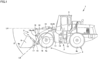
- a wheel loader 1 will be described by way of example of a work vehicle.
- Fig. 1 is a side view of wheel loader 1 which is one example of the work vehicle according to the embodiment.
- wheel loader 1 includes a vehicular body frame 2, a work implement 3, a traveling apparatus 4, and a cab 5.
- a vehicular body of wheel loader 1 is constituted of vehicular body frame 2, cab 5 and the like.
- Work implement 3 and traveling apparatus 4 are attached to the vehicular body of wheel loader 1.
- Traveling apparatus 4 causes the vehicular body of wheel loader 1 to travel, and includes running wheels 4a and 4b.
- Wheel loader 1 is movable as running wheels 4a and 4b are rotationally driven, and can perform a desired work using work implement 3.
- Vehicular body frame 2 includes a front frame 11 and a rear frame 12. Front frame 11 and rear frame 12 are attached to each other so as to be swingable in a left-right direction.
- a steering cylinder 13 is attached to front frame 11 and rear frame 12. Steering cylinder 13 is a hydraulic cylinder. When steering cylinder 13 extends and contracts by a hydraulic oil from a steering pump (not shown), a direction of travel of wheel loader 1 is laterally changed.
- a direction in which wheel loader 1 travels straightforward is referred to as a front-rear direction of wheel loader 1.
- a front-rear direction of wheel loader 1 a side where work implement 3 is arranged with respect to vehicular body frame 2 is referred to as a frontward direction, and a side opposite to the frontward direction is referred to as a rearward direction.
- a left-right direction of wheel loader 1 is a direction orthogonal to the front-rear direction as seen in a plan view.
- a right side and a left side in the left-right direction when facing front are defined as a right direction and a left direction, respectively.
- a top-bottom direction of wheel loader 1 is a direction orthogonal to a plane defined by the front-rear direction and the left-right direction.
- a ground side is defined as a lower side and a sky side is defined as an upper side.
- the front-rear direction refers to a front-rear direction with respect to an operator sitting on an operator's seat in cab 5.
- the left-right direction refers to a left-right direction with respect to the operator sitting on the operator's seat.
- the left-right direction refers to a vehicular width direction of wheel loader 1.
- the top-bottom direction refers to a top-bottom direction with respect to the operator sitting on the operator's seat.
- a direction in which the operator sitting on the operator's seat faces is defined as the frontward direction
- a backward direction with respect to the operator sitting on the operator's seat is defined as the rearward direction.
- a right side and a left side when the operator sitting on the operator's seat faces front are defined as the right direction and the left direction, respectively.
- a foot side and a head side of the operator sitting on the operator's seat are defined as the lower side and the upper side, respectively.
- Work implement 3 and running wheel (front wheel) 4a are attached to front frame 11.
- Work implement 3 includes a boom 14 and a bucket 6.
- a base end of boom 14 is rotatably attached to front frame 11 by a boom pin 10.
- Bucket 6 is rotatably attached to boom 14 by a bucket pin 17 located at a tip of boom 14.
- Front frame 11 and boom 14 are coupled to each other by a boom cylinder 16.
- Boom cylinder 16 is a hydraulic cylinder. When boom cylinder 16 extends and contracts by a hydraulic oil from a work implement pump 25 (see Fig. 2 ), boom 14 is raised and lowered.
- Boom cylinder 16 drives boom 14.
- Work implement 3 further includes a bell crank 18, a tilt cylinder 19 and a tilt rod 15.
- Bell crank 18 is rotatably supported on boom 14 by a support pin 18a located substantially in the center of boom 14.
- Tilt cylinder 19 couples a base end of bell crank 18 to front frame 11.
- Tilt rod 15 couples a tip of bell crank 18 to bucket 6.
- Tilt cylinder 19 is a hydraulic cylinder. When tilt cylinder 19 extends and contracts by the hydraulic oil from work implement pump 25 (see Fig. 2 ), bucket 6 pivots upward and downward. Tilt cylinder 19 drives bucket 6.
- Cab 5 and running wheel (rear wheel) 4b are attached to rear frame 12.
- Cab 5 is arranged behind boom 14.
- Cab 5 is placed on vehicular body frame 2.
- a seat on which the operator sits, an operation apparatus and the like are arranged in cab 5.
- FIG. 2 is a schematic block diagram showing a configuration of wheel loader 1.
- Wheel loader 1 includes an engine 20, a motive power extraction unit 22, a motive power transfer mechanism 23, a cylinder driving unit 24, a first angle detector 29, a second angle detector 48, and a first processor 30 (controller).
- Engine 20 is, for example, a diesel engine. An output of engine 20 is controlled by adjusting an amount of fuel injected into a cylinder of engine 20.
- Motive power extraction unit 22 is a device that divides the output of engine 20 into motive power transfer mechanism 23 and cylinder driving unit 24.
- Motive power transfer mechanism 23 is a mechanism that transfers the driving force from engine 20 to front wheel 4a and rear wheel 4b, and is a transmission, for example.
- Motive power transfer mechanism 23 changes a speed of rotation of an input shaft 21 and outputs the rotation to an output shaft 23a.
- a vehicle speed detection unit 27 that detects a vehicle speed of wheel loader 1 is attached to output shaft 23a of motive power transfer mechanism 23.
- Wheel loader 1 includes vehicle speed detection unit 27.
- Vehicle speed detection unit 27 is, for example, a vehicle speed sensor. Vehicle speed detection unit 27 detects a rotation speed of output shaft 23a, thereby detecting a movement speed of wheel loader 1 by traveling apparatus 4 ( Fig. 1 ). Vehicle speed detection unit 27 functions as a rotation sensor that detects the rotation speed of output shaft 23a. Vehicle speed detection unit 27 functions as a movement detector that detects the movement by traveling apparatus 4. Vehicle speed detection unit 27 outputs a detection signal indicating the vehicle speed of wheel loader 1 to first processor 30.
- Cylinder driving unit 24 includes work implement pump 25 and a control valve 26.
- the output of engine 20 is transferred to work implement pump 25 through motive power extraction unit 22.
- the hydraulic oil discharged from work implement pump 25 is supplied to boom cylinder 16 and tilt cylinder 19 through control valve 26.
- First hydraulic pressure detectors 28a and 28b that detect a hydraulic pressure in an oil chamber of boom cylinder 16 are attached to boom cylinder 16.
- Wheel loader 1 includes first hydraulic pressure detectors 28a and 28b.
- First hydraulic pressure detectors 28a and 28b include, for example, a pressure sensor 28a for detection of a head pressure, and a pressure sensor 28b for detection of a bottom pressure.
- Pressure sensor 28a is attached to the head side of boom cylinder 16. Pressure sensor 28a can detect a pressure (head pressure) of the hydraulic oil in the cylinder-head-side oil chamber of boom cylinder 16. Pressure sensor 28a outputs a detection signal indicating the head pressure of boom cylinder 16 to first processor 30.
- Pressure sensor 28b is attached to the bottom side of boom cylinder 16. Pressure sensor 28b can detect a pressure (bottom pressure) of the hydraulic oil in the cylinder-bottom-side oil chamber of boom cylinder 16. Pressure sensor 28b outputs a detection signal indicating the bottom pressure of boom cylinder 16 to first processor 30.
- First angle detector 29 is, for example, a potentiometer attached to boom pin 10. First angle detector 29 detects a boom angle indicating a lift angle (tilt angle) of boom 14. First angle detector 29 outputs a detection signal indicating the boom angle to first processor 30.
- a boom angle ⁇ refers to an angle of a straight line LB extending in a direction from a center of boom pin 10 toward a center of bucket pin 17, with respect to a horizontal line extending forward from the center of boom pin 10.
- a case in which straight line LB is located above the horizontal line is defined as positive boom angle ⁇ .
- a case in which straight line LB is located below the horizontal line is defined as negative boom angle ⁇ .
- First angle detector 29 may be a stroke sensor arranged in boom cylinder 16.
- Second angle detector 48 is, for example, a potentiometer attached to support pin 18a. Second angle detector 48 detects an angle (bell crank angle) of bell crank 18 with respect to boom 14, thereby detecting a bucket angle indicating a tilt angle of bucket 6 with respect to boom 14. Second angle detector 48 outputs a detection signal indicating the bucket angle to first processor 30.
- the bucket angle is, for example, an angle formed by straight line LB and a straight line that connects a center of bucket pin 17 and a cutting edge 6a of bucket 6.
- Second angle detector 48 may be a stroke sensor arranged in tilt cylinder 19.
- wheel loader 1 includes, in cab 5, an operation apparatus operated by the operator.
- the operation apparatus includes a forward and rearward movement switching apparatus 49, an accelerator operation apparatus 51, a boom operation apparatus 52, a speed change operation apparatus 53, a bucket operation apparatus 54, and a brake operation apparatus 58.
- Forward and rearward movement switching apparatus 49 includes a forward and rearward movement switching operation member 49a and a forward and rearward movement switching detection sensor 49b.
- Forward and rearward movement switching operation member 49a is operated by the operator to provide an instruction to switch between forward movement and rearward movement of the vehicle.
- Forward and rearward movement switching operation member 49a can be switched to each of a forward movement (F) position, a neutral (N) position and a rearward movement (R) position.
- Forward and rearward movement switching detection sensor 49b detects a position of forward and rearward movement switching operation member 49a.
- Forward and rearward movement switching detection sensor 49b outputs, to first processor 30, a detection signal (forward movement, neutral, rearward movement) about the forward and rearward movement instruction indicated by the position of forward and rearward movement switching operation member 49a.
- Forward and rearward movement switching apparatus 49 includes an FNR switching lever that can perform switching among forward movement (F), neutral (N) and rearward movement (R).
- Accelerator operation apparatus 51 includes an accelerator operation member 51a and an accelerator operation detection unit 51b. Accelerator operation member 51a is operated by the operator to set a target rotation speed of engine 20. Accelerator operation detection unit 51b detects an amount of operation (amount of accelerator operation) of accelerator operation member 51a. Accelerator operation detection unit 51b outputs a detection signal indicating the amount of accelerator operation to first processor 30.
- Brake operation apparatus 58 includes a brake operation member 58a and a brake operation detection unit 58b.
- Brake operation member 58a is operated by the operator to control the deceleration force of wheel loader 1.
- Brake operation detection unit 58b detects an amount of operation (amount of brake operation) of brake operation member 58a.
- Brake operation detection unit 58b outputs a detection signal indicating the amount of brake operation to first processor 30.
- a pressure of a brake oil may be used as the amount of brake operation.
- Boom operation apparatus 52 includes a boom operation member 52a and a boom operation detection unit 52b.
- Boom operation member 52a is operated by the operator to raise or lower boom 14.
- Boom operation detection unit 52b detects a position of boom operation member 52a.
- Boom operation detection unit 52b outputs, to first processor 30, a detection signal about the boom 14-raising instruction or the boom 14-lowering instruction indicated by the position of boom operation member 52a.
- Speed change operation apparatus 53 includes a speed change operation member 53a and a speed change operation detection unit 53b.
- Speed change operation member 53a is operated by the operator to control a speed change from input shaft 21 to output shaft 23a in motive power transfer mechanism 23.
- Speed change operation detection unit 53b detects a position of speed change operation member 53a.
- Speed change operation detection unit 53b outputs, to first processor 30, a detection instruction about the speed change indicated by the position of speed change operation member 53a.
- Bucket operation apparatus 54 includes a bucket operation member 54a and a bucket operation detection unit 54b.
- Bucket operation member 54a is operated by the operator to cause bucket 6 to perform an excavation operation or a dumping operation.
- Bucket operation detection unit 54b detects a position of bucket operation member 54a.
- Bucket operation detection unit 54b outputs, to first processor 30, a detection signal about the instruction to operate bucket 6 in a tilting back direction or a dumping direction, which is indicated by the position of bucket operation member 54a.
- First angle detector 29, second angle detector 48, first hydraulic pressure detectors 28a and 28b, boom operation detection unit 52b, and bucket operation detection unit 54b are included in a work implement sensor.
- the work implement sensor senses a state of work implement 3.
- a load weight W in bucket 6 can be calculated from a detection value of the work implement sensor.
- the work implement sensor includes at least one of a pressure sensor or a strain sensor.
- the work implement sensor includes a work implement position sensor.
- the work implement position sensor is, for example, constituted of first angle detector 29, second angle detector 48, boom operation detection unit 52b, and bucket operation detection unit 54b.
- forward and rearward movement switching apparatus 49 vehicle speed detection unit 27, accelerator operation detection unit 51b, and brake operation detection unit 58b are included in a traveling sensor.
- the traveling sensor senses a traveling state of traveling apparatus 4.
- First processor 30 is implemented by a microcomputer including a storage device such as a RAM (Random Access Memory) and a ROM (Read Only Memory), and a computing device such as a CPU (Central Processing Unit).
- First processor 30 may be implemented as a part of the function of the controller of wheel loader 1 that controls the operation of engine 20, work implement 3 (such as boom cylinder 16 and tilt cylinder 19), motive power transfer mechanism 23 and the like.
- the signal about the forward and rearward movement instruction detected by forward and rearward movement switching apparatus 49, the signal about the vehicle speed of wheel loader 1 detected by vehicle speed detection unit 27, the signal about the boom angle detected by first angle detector 29, the signal about the head pressure of boom cylinder 16 detected by pressure sensor 28a, and the signal about the bottom pressure of boom cylinder 16 detected by pressure sensor 28b are mainly input to first processor 30.
- first processor 30 Based on the above-described input signals, first processor 30 sums the transportation work information about a load in bucket 6.
- the transportation work information includes, for example, the load weight of the load in bucket 6.
- Wheel loader 1 further includes a display 40 and an output unit 45.
- Display 40 is implemented by a monitor arranged in cab 5 and viewed by the operator.
- Display 40 displays the transportation work information obtained by first processor 30.
- Output unit 45 outputs the transportation work information to a server (second processor 70) placed outside wheel loader 1.
- Output unit 45 may, for example, have a communication function such as wireless communication to communicate with an input unit 71 of second processor 70.
- output unit 45 may, for example, be an interface of a portable storage device (such as a memory card) that can be accessed by input unit 71 of second processor 70.
- Second processor 70 includes a display 75 corresponding to a monitor function, and can cause display 75 to display the transportation work information output from output unit 45.
- First processor 30 shown in Fig. 2 determines a loaded state of bucket 6, and when receiving, from the traveling sensor, a rearward movement state switching signal indicating that traveling apparatus 4 has performed an operation for shifting from a rearward movement state to a state other than the rearward movement state in the loaded state, calculates the load weight of bucket 6 from the detection value of the work implement sensor based on the rearward movement state switching signal.
- Functional blocks of first processor 30 having the above-described function will be described below.
- first processor 30 mainly includes, for example, a loaded state determination unit 30a, a rearward movement switching sensing unit 30b, a load weight calculation unit 30c, a soil ejection sensing unit 30d, a load weight output unit 30e, a load weight summation unit 30f, a summation value output unit 30g, a boom angle sensing unit 30h, a differential pressure sensing unit 30i, and a storage unit 30j.
- Loaded state determination unit 30a determines whether bucket 6 is in a loaded state or in an unloaded state. Based on the detection signal indicating the boom angle which is output from first angle detector 29 and the detection signal indicating the bucket angle which is output from second angle detector 48, loaded state determination unit 30a determines whether or not work implement 3 has performed the excavation operation or the piling operation. When work implement 3 has performed the excavation operation, bucket 6 is in the loaded state in which bucket 6 contains a load (excavated object) such as soil therein. In contrast, when work implement 3 has performed the piling operation, bucket 6 is in the unloaded state in which bucket 6 is empty. A determination signal from loaded state determination unit 30a is output to rearward movement switching sensing unit 30b.
- Rearward movement switching sensing unit 30b senses the traveling state of traveling apparatus 4, based on at least one of the detection signal (forward movement, neutral, rearward movement) about the forward and rearward movement instruction output from forward and rearward movement switching apparatus 49 and the detection signal indicating the vehicle speed of wheel loader 1 which is output from vehicle speed detection unit 27. After rearward movement switching sensing unit 30b receives the determination signal from loaded state determination unit 30a, rearward movement switching sensing unit 30b senses whether traveling apparatus 4 has been switched from the rearward movement state to a forward movement state or from the rearward movement state to a neutral state. A sensing signal about the traveling state from rearward movement switching sensing unit 30b is output to load weight calculation unit 30c.
- Load weight calculation unit 30c calculates load weight W in bucket 6, based on a boom angle signal output from boom angle sensing unit 30h and a differential pressure signal output from differential pressure sensing unit 30i.
- Boom angle sensing unit 30h receives the detection signal indicating the boom angle which is output from first angle detector 29, calculates a boom angle, and outputs a signal about the calculated boom angle to load weight calculation unit 30c.
- Differential pressure sensing unit 30i calculates a differential pressure between the head pressure and the bottom pressure of boom cylinder 16, based on the detection signal indicating the head pressure of boom cylinder 16 which is output from pressure sensor 28a and the detection signal indicating the bottom pressure of boom cylinder 16 which is output from pressure sensor 28b, and outputs a signal about the calculated differential pressure to load weight calculation unit 30c.
- a method for calculating load weight W in load weight calculation unit 30c will be described in detail below.
- a signal about load weight W in bucket 6 calculated by load weight calculation unit 30c is output to soil ejection sensing unit 30d.
- soil ejection sensing unit 30d determines whether or not the load (such as soil) in bucket 6 has been ejected from bucket 6. Soil ejection sensing unit 30d determines whether or not work implement 3 has performed a soil ejection operation, based on the detection signal indicating the boom angle which is output from first angle detector 29 and the detection signal indicating the bucket angle which is output from second angle detector 48. When work implement 3 has performed the soil ejection operation, bucket 6 is in the unloaded state in which bucket 6 is empty. In contrast, when work implement 3 has not performed the soil ejection operation, bucket 6 remains in the loaded state in which bucket 6 contains the load such as soil therein. A determination signal from soil ejection sensing unit 30d is output to load weight output unit 30e.
- Load weight output unit 30e receives the determination signal from soil ejection sensing unit 30d, and outputs the load weight signal calculated by load weight calculation unit 30c to load weight summation unit 30f, storage unit 30j and display 40.
- Storage unit 30j stores load weight W output from load weight output unit 30e.
- Display 40 displays load weight W on a screen and the like.
- Load weight output unit 30e may also output the load weight signal to output unit 45 ( Fig. 2 ).
- the load weight signal output to output unit 45 may be output to second processor 70 and displayed on display 75 of second processor 70.
- Load weight summation unit 30f receives the load weight signal from load weight output unit 30e, and adds the current load weight to the previous load weights stored in storage unit 30j. Load weight summation unit 30f outputs a signal about a summation value of the summed load weights to summation value output unit 30g.
- Summation value output unit 30g receives the summation value signal from load weight summation unit 30f, and outputs the summation value signal obtained by summation in load weight summation unit 30f to storage unit 30j and display 40.
- Storage unit 30j stores the summation value of load weights W output from summation value output unit 30g.
- Display 40 displays the summation value of load weights W on the screen and the like.
- Summation value output unit 30g may also output the summation value signal to output unit 45 ( Fig. 2 ).
- the summation value signal output to output unit 45 may be output to second processor 70 and displayed on display 75 of second processor 70.
- Fig. 4 shows one example of a relationship between a boom angle ⁇ and a differential pressure P ⁇ for each instantaneous load W.
- curves A, B and C represent a case in which bucket 6 is empty, a case in which bucket 6 is loaded half, and a case in which bucket 6 is fully loaded, respectively.
- a graph of a relationship between boom angle ⁇ and differential pressure P ⁇ at two or more instantaneous loads W measured preliminarily a graph of a relationship between instantaneous load W and differential pressure P ⁇ for each boom angle ⁇ as shown in Fig. 5 can be obtained. Therefore, when boom angle ⁇ and differential pressure P ⁇ are known, an instantaneous load WN in each differential pressure sampling can be obtained.
- instantaneous load WN is determined by linear interpolation.
- instantaneous load WN can also be obtained based on a numerical table that prestores the above-described relationship.
- Wheel loader 1 performs the excavation operation for scooping an excavated object such as soil into bucket 6, and the loading operation for loading the load (excavated object 100) in bucket 6 into a transportation machine such as a dump truck 200.
- Fig. 6 is a schematic view showing an example of a series of steps that form the excavation operation and the loading operation of wheel loader 1 based on the embodiment. By repeating the sequential execution of a plurality of steps described below, wheel loader 1 excavates excavated object 100 and loads excavated object 100 into the transportation machine such as dump truck 200.
- wheel loader 1 moves forward toward excavated object 100.
- the operator operates boom cylinder 16 and tilt cylinder 19 to cause work implement 3 to take an excavation posture in which the tip of boom 14 is located at a low position and bucket 6 faces horizontally, and causes wheel loader 1 to move forward toward excavated object 100.
- the scooping step may be completed simply by tilting back bucket 6 once.
- an operation for tilting back bucket 6 to bring bucket 6 into neutral, and then, tilting back bucket 6 again may be repeated in the scooping step.
- Fig. 6(D) after excavated object 100 is scooped into bucket 6, the operator causes wheel loader 1 to move rearward in a loaded rearward movement step.
- the operator may perform boom-raising during rearward movement, or may perform boom-raising during forward movement in Fig. 6(E) .
- the operator dumps bucket 6 at a prescribed position, and loads the load (excavated object) in bucket 6 onto the truck bed of dump truck 200.
- This step is a so-called soil ejection step.
- the operator lowers boom 14 while causing wheel loader 1 to move rearward, and returns bucket 6 to the excavation posture.
- Fig. 7 is a table showing a determination method in the series of steps that form the excavation work and the loading work of wheel loader 1.
- the uppermost line of "work step” shows the designation of the work step shown in each of Figs. 6(A) to 6(F) .
- the lines of "forward and rearward movement switching lever”, “work implement operation” and “work implement cylinder pressure” below the uppermost line show various determination criteria used by first processor 30 ( Figs. 2 and 3 ) to determine which step a current work step is.
- the line of "forward and rearward movement switching lever” shows a determination criterion about the forward and rearward movement switching lever, using a circle mark.
- the line of "work implement operation” shows a determination criterion about an operation performed on work implement 3 by the operator, using a circle mark. More specifically, the line of "boom” shows a determination criterion about an operation performed on boom 14, and the line of "bucket” shows a determination criterion about an operation performed on bucket 6.
- the line of "work implement cylinder pressure” shows a determination criterion about a current hydraulic pressure of a cylinder of work implement 3, e.g., a hydraulic pressure of the cylinder bottom chamber of boom cylinder 16.
- Four reference values A, B, C, and P are preset for the hydraulic pressure, and a plurality of pressure ranges (a range lower than reference value P, a range from reference values A to C, a range from reference values B to P, and a range lower than reference value C) are defined based on these reference values A, B, C, and P, and these pressure ranges are set as the above-described determination criterion.
- the magnitude of four reference values A, B, C, and P is defined as A>B>C>P.
- first processor 30 can determine which step a current step is.
- first processor 30 when performing the control shown in Fig. 7 will be described below.
- a combination of determination criteria for "forward and rearward movement switching lever", “boom”, “bucket”, and “work implement cylinder pressure” corresponding to each work step shown in Fig. 7 is prestored in storage unit 30j ( Fig. 2 ).
- First processor 30 recognizes the currently selected forward and rearward movement switching lever (F, N or R), based on a signal from forward and rearward movement switching apparatus 49.
- First processor 30 recognizes a type (lowering, neutral or raising) of a current operation performed on boom 14, based on a signal from boom operation detection unit 52b.
- First processor 30 recognizes a type (dumping, neutral or tilting back) of a current operation performed on bucket 6, based on a signal from bucket operation detection unit 54b.
- first processor 30 recognizes a current hydraulic pressure of the cylinder bottom chamber of boom cylinder 16, based on a signal from pressure sensor 28b shown in Fig. 2 .
- First processor 30 compares a combination of the recognized current forward and rearward movement switching lever, boom operation type, bucket operation type, and lift cylinder hydraulic pressure (i.e., a current work state) with the prestored combination of determination criteria for "forward and rearward movement switching lever", “boom”, “bucket”, and “work implement cylinder pressure” corresponding to each work step. As a result of this comparison process, first processor 30 determines which work step the combination of determination criteria matching the current work state best corresponds to.
- the forward and rearward movement switching lever is F
- the boom operation and the bucket operation are both neutral
- the work implement cylinder pressure is lower than reference value P.
- the forward and rearward movement switching lever is F
- the boom operation and the bucket operation are both neutral
- the work implement cylinder pressure is in the range from reference values A to C.
- the forward and rearward movement switching lever is F or R
- the boom operation is raising or neutral
- the bucket operation is tilting back
- the work implement cylinder pressure is in the range from reference values A to C.
- a determination criterion that tilting back and neutral are alternately repeated may be further added. This is because, depending on the state of the excavated object, the operation for tilting back bucket 6 to bring bucket 6 into neutral, and then, tilting back bucket 6 again may be repeated.
- the forward and rearward movement switching lever is R
- the boom operation is neutral or raising
- the bucket operation is neutral
- the work implement cylinder pressure is in the range from reference values B to P.
- the forward and rearward movement switching lever is F
- the boom operation is raising or neutral
- the bucket operation is neutral
- the work implement cylinder pressure is in the range from reference values B to P.
- the forward and rearward movement switching lever is F
- the boom operation is raising or neutral
- the bucket operation is dumping
- the work implement cylinder pressure is in the range from reference values B to P.
- the forward and rearward movement switching lever is R
- the boom operation is lowering
- the bucket operation is tilting back
- the work implement cylinder pressure is lower than reference value P.
- wheel loader 1 measures load weight W in bucket 6 and calculates the summation value of load weights W.
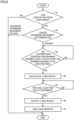
- Fig. 8 is a flowchart showing a method for controlling the work vehicle including a method for measuring the load weight in the above-described excavation and loading operation.
- wheel loader 1 moves forward toward the excavated object. As shown in Figs. 6(A) and 6(B) , wheel loader 1 moves forward toward excavated object 100 and until cutting edge 6a of bucket 6 bites into excavated object 100.
- step S1 it is determined whether or not excavation has been performed, as shown in Fig. 8 (step S1).
- a loaded rearward movement determination is then performed (step S2). Specifically, when bucket 6 is dumped after excavated object 100 is scooped into bucket 6 and before wheel loader 1 moves rearward, the piling operation or the like is performed and it is determined that wheel loader 1 is in the unloaded rearward movement state. In contrast, when wheel loader 1 moves rearward without dumping bucket 6 after excavated object 100 is scooped into bucket 6, the bucket loading operation is performed and it is determined that bucket 6 is in the loaded state.
- “Loaded” herein refers to a state in which bucket 6 contains the load therein, and “unloaded” refers to a state in which bucket 6 does not contain the load therein.
- This loaded rearward movement determination is performed in loaded state determination unit 30a and rearward movement switching sensing unit 30b of first processor 30 shown in Fig. 3 .
- a determination as to whether or not bucket 6 has been dumped is performed based on the detection signal (sensor signal) indicating the bucket angle which is output from second angle detector 48 included in the work implement sensor.
- detection signal sensor signal
- wheel loader 1 moves rearward without dumping bucket 6, it is determined that the bucket loaded rearward movement operation has been performed.
- step S3 when wheel loader 1 moves rearward to a prescribed position, it is determined whether or not the operator has shifted wheel loader 1 from the rearward movement state to a state other than the rearward movement state (step S3).
- a state other than the rearward movement state refers to the forward movement state or the neutral (stop) state.
- the shift from the rearward movement state to a state other than the rearward movement state is sensed by rearward movement switching sensing unit 30b shown in Fig. 3 .
- the shift from the rearward movement state to a state other than the rearward movement state is sensed based on, for example, whether or not the operator has operated forward and rearward movement switching operation member 49a of forward and rearward movement switching apparatus 49 shown in Fig. 2 from the rearward movement (R) position to the forward movement (F) position or the neutral (N) position.
- the rearward movement state switching signal (signal indicating forward movement or neutral) is output from forward and rearward movement switching apparatus 49 (forward and rearward movement switching detection sensor 49b) shown in Fig. 3 to rearward movement switching sensing unit 30b. Therefore, based on this rearward movement state switching signal, rearward movement switching sensing unit 30b can sense that the traveling state has been switched from the rearward movement state to the other state (forward movement or stop).
- the shift from the rearward movement state to a state other than the rearward movement state may be sensed based on, for example, the movement speed of wheel loader 1 sensed by vehicle speed detection unit 27 shown in Fig. 2 .
- vehicle speed detection unit 27 shows the movement speed of wheel loader 1 sensed by vehicle speed detection unit 27 shown in Fig. 2 .
- the traveling state has been switched from the rearward movement state to the other state
- the movement speed of wheel loader 1 sensed by vehicle speed detection unit 27 changes from a speed in a rearward movement direction to a speed in a forward movement direction, or changes to zero. Therefore, based on the signal (rearward movement state switching signal) about the movement speed of wheel loader 1 indicating forward movement or stop which is output from vehicle speed detection unit 27, rearward movement switching sensing unit 30b shown in Fig. 3 can sense that the traveling state has been switched from the rearward movement state to the other state (forward movement or stop).
- wheel loader 1 continues to move rearward.
- load weight W in bucket 6 is calculated (step S4).
- Load weight W is calculated by load weight calculation unit 30c shown in Fig. 3 .
- load weight calculation unit 30c calculates load weight W in bucket 6, based on the boom angle signal output from boom angle sensing unit 30h based on the detection value of first angle detector 29, and the differential pressure signal output from differential pressure sensing unit 30i based on the detection values of first hydraulic pressure detectors 28a and 28b.
- first processor 30 shown in Fig. 3 can calculate load weight W of bucket 6 from the detection value of the work implement sensor (first hydraulic pressure detectors 28a and 28b, and first angle detector 29) based on the rearward movement state switching signal, when first processor 30 receives the rearward movement state switching signal from the traveling sensor (forward and rearward movement switching detection sensor 49b and vehicle speed detection unit 27), the rearward movement state switching signal indicating that the operation for shifting from the rearward movement state to a state other than the rearward movement state has been performed.
- step S5 After a prescribed time period elapses since wheel loader 1 moves forward or stops, it is sensed whether or not work implement 3 has performed the soil ejection operation (step S5).
- This soil ejection operation by work implement 3 is performed by dumping bucket 6 as shown in Fig. 6(F) .
- a determination as to whether or not bucket 6 has been dumped is performed based on the detection signal indicating the bucket angle which is output from second angle detector 48 shown in Fig. 2 . Therefore, as shown in Fig. 3 , based on the signal about the bucket angle output from second angle detector 48, soil ejection sensing unit 30d can sense whether or not soil ejection has been performed.
- step S6 load weight W of the load in bucket 6 is output (step S6).
- Load weight W is output by load weight output unit 30e of first processor 30 shown in Fig. 3 outputting the signal about load weight W to storage unit 30j or display 40.
- the signal about load weight W is stored in storage unit 30j and displayed on display 40, or displayed on display 75 of second processor 70.
- load weight output unit 30e of first processor 30 outputs load weight W based on the soil ejection signal.
- load weights W are summed based on output load weight W (step S7).
- Load weights W are summed by load weight summation unit 30f of first processor 30 shown in Fig. 3 automatically adding the current load weight to the previous load weights stored in storage unit 30j (i.e., automatically summing a plurality of load weights).
- the summation value obtained by summation is output from load weight summation unit 30f and input to summation value output unit 30g.
- the summation value obtained by summation is stored in storage unit 30j by summation value output unit 30g and displayed on display 40, or displayed on display 75 of second processor 70.
- control of the work vehicle including measurement and summation of the load weight in the excavation and loading operation in the present embodiment is performed.
- the present inventor researched a change in boom angle, boom cylinder differential pressure, instantaneous load, and load weight in the series of steps of the excavation and loading operation of wheel loader 1 according to the present embodiment. The result is shown in Fig. 9 .
- each of the boom angle, the boom cylinder differential pressure and the instantaneous load changes significantly during excavation and during soil ejection. It can also be seen that each of the boom angle, the boom cylinder differential pressure and the instantaneous load also changes significantly in the first half of loaded rearward movement. In contrast, in the latter half of loaded rearward movement and during loaded forward movement, a change over time in each of boom angle, boom cylinder differential pressure and instantaneous load is small. Particularly, immediately before switching from loaded rearward movement to loaded forward movement, a change over time in each of boom cylinder differential pressure and instantaneous load is very small, and thus, it can be seen that each of the boom cylinder differential pressure and the instantaneous load is stable.
- a change over time in each of boom cylinder differential pressure and instantaneous load is very small around the time when the traveling state is switched from the rearward movement state (loaded rearward movement) to the forward movement state (loaded forward movement) in the loaded state.
- the load weight of bucket 6 is calculated based on the rearward movement state switching signal indicating that traveling apparatus 4 has performed the operation for shifting from the rearward movement state to a state other than the rearward movement state in the loaded state.
- load weight W is measured around the time when the traveling state is switched from the rearward movement state to the forward movement state.
- load weight W can be accurately measured. Therefore, the load weight may be calculated based on the instantaneous load immediately after the forward and rearward movement switching lever is switched from rearward movement to forward movement.
- the load weight may be calculated based on the actual vehicle speed reaching 0 km/h, or may be calculated based on the actual vehicle speed shifting to forward movement. Alternatively, the load weight may be calculated based on a combination of these.
- the load weight is preferably calculated by the time the vehicle speed reaches 0 km/h.
- the load weight may be calculated during a time period in which the vehicle speed is equal to or lower than a prescribed speed.
- a time region in which a change over time in boom cylinder differential pressure and instantaneous load is small may vary in some cases. Therefore, the timing of calculation of the load weight may be changeable.
- the loaded state of bucket 6 is determined by determining whether or not the work implement is in the piling state based on the sensor signal from the work implement sensor. Accordingly, summation of load weights W when bucket 6 is in the unloaded state can be prevented, and thus, the accurate summation value of load weights W can be obtained.
- the soil ejection signal indicating that work implement 3 has ejected soil is received from the work implement sensor (e.g., second angle detector 48) and load weight W is output based on the soil ejection signal. Accordingly, output of the load weight before soil ejection can be prevented, and thus, the summation value of load weights W after soil ejection can be accurately obtained.
- first processor 30 automatically sums a plurality of load weights W. Accordingly, the accurate summation value of load weights W can be obtained.
- the work implement sensor includes at least one of a pressure sensor or a strain sensor. Accordingly, the degree of freedom in sensor selection is increased.
- the work implement sensor further includes a work implement position sensor. Accordingly, the position of the work implement can also be detected.
- the traveling sensor includes at least one of forward and rearward movement switching detection sensor 49b and vehicle speed detection unit 27. Accordingly, the operation for shifting from the rearward movement state to a state other than the rearward movement state can be sensed based on at least one of the position of forward and rearward movement switching operation member 49a in forward and rearward movement switching apparatus 49 and the vehicle speed sensed by vehicle speed detection unit 27.
- Vehicle speed detection by a GPS (Global Positioning System), vehicle speed detection using a stereo camera, vehicle speed detection using a rotation sensor of a transmission output shaft, vehicle speed detection using a rotation sensor of a transmission input shaft and a transmission gear ratio, and the like may be used as the traveling sensor.
- the traveling sensor is not limited to the foregoing, and anything that can detect the traveling direction of the vehicular body may be used.
- load weight W may be calculated from the boom angle and the bottom pressure of boom cylinder 16. In this case, pressure sensor 28a in Fig. 2 is unnecessary.
- boom operation apparatus 52 and bucket operation apparatus 54 may be an integrated steering lever (single lever). In this case, one steering lever serves as both boom operation apparatus 52 and bucket operation apparatus 54.
- second processor 70 shown in Fig. 2 may receive and transmit an electric/radio signal to and from output unit 45 by a CAN (Controller Area Network), a LAN (Local Area Network), a wireless LAN and the like.
- CAN Controller Area Network
- LAN Local Area Network
- wireless LAN wireless LAN
- second processor 70 may receive the input information of first processor 30 and perform a computation.
- wheel loader 1 shown in Fig. 1 has been described by way of example of a work vehicle to which the configuration of the above-described embodiment is applied.
- the work vehicle to which the configuration of the above-described embodiment is applied may be a work vehicle including bucket 6 and being capable of moving forward and rearward, and may be, for example, a backhoe loader.
Landscapes
- Engineering & Computer Science (AREA)
- Mining & Mineral Resources (AREA)
- Civil Engineering (AREA)
- General Engineering & Computer Science (AREA)
- Structural Engineering (AREA)
- Physics & Mathematics (AREA)
- General Physics & Mathematics (AREA)
- Mechanical Engineering (AREA)
- Operation Control Of Excavators (AREA)
- Component Parts Of Construction Machinery (AREA)
Applications Claiming Priority (2)
| Application Number | Priority Date | Filing Date | Title |
|---|---|---|---|
| JP2018038576A JP6971888B2 (ja) | 2018-03-05 | 2018-03-05 | 作業車両、作業車両を含むシステムおよび作業車両の積載重量算出方法 |
| PCT/JP2019/004820 WO2019171885A1 (ja) | 2018-03-05 | 2019-02-12 | 作業車両、作業車両を含むシステムおよび作業車両の積載重量算出方法 |
Publications (3)
| Publication Number | Publication Date |
|---|---|
| EP3677882A1 EP3677882A1 (en) | 2020-07-08 |
| EP3677882A4 EP3677882A4 (en) | 2021-06-09 |
| EP3677882B1 true EP3677882B1 (en) | 2024-04-03 |
Family
ID=67846673
Family Applications (1)
| Application Number | Title | Priority Date | Filing Date |
|---|---|---|---|
| EP19763381.1A Active EP3677882B1 (en) | 2018-03-05 | 2019-02-12 | Work vehicle, system including work vehicle, and load weight calculation method for work vehicle |
Country Status (5)
| Country | Link |
|---|---|
| US (1) | US11536008B2 (ja) |
| EP (1) | EP3677882B1 (ja) |
| JP (1) | JP6971888B2 (ja) |
| CN (1) | CN111373228B (ja) |
| WO (1) | WO2019171885A1 (ja) |
Families Citing this family (4)
| Publication number | Priority date | Publication date | Assignee | Title |
|---|---|---|---|---|
| JP7123591B2 (ja) * | 2018-03-22 | 2022-08-23 | 株式会社小松製作所 | 作業機械、および作業機械を含むシステム |
| USD1020926S1 (en) * | 2018-12-12 | 2024-04-02 | Bruder Spielwaren Gmbh + Co. Kg | Toy |
| JP7374762B2 (ja) * | 2019-12-27 | 2023-11-07 | 株式会社小松製作所 | 作業機械、計量方法、および作業機械を含むシステム |
| JP7481983B2 (ja) * | 2020-09-30 | 2024-05-13 | 株式会社小松製作所 | 作業機械および作業機械の制御方法 |
Family Cites Families (23)
| Publication number | Priority date | Publication date | Assignee | Title |
|---|---|---|---|---|
| JPS6080721A (ja) * | 1983-10-11 | 1985-05-08 | Caterpillar Mitsubishi Ltd | 積荷重量計測装置 |
| JP2613456B2 (ja) * | 1988-11-11 | 1997-05-28 | 東洋運搬機株式会社 | ホイルローダの作業分析システム |
| US5067572A (en) * | 1990-08-20 | 1991-11-26 | Caterpillar Inc. | Dynamic payload monitor |
| US5850341A (en) * | 1994-06-30 | 1998-12-15 | Caterpillar Inc. | Method and apparatus for monitoring material removal using mobile machinery |
| JP2001099701A (ja) | 1999-09-30 | 2001-04-13 | Komatsu Ltd | 積込車両の積載重量計測装置 |
| US7395184B2 (en) | 2004-01-15 | 2008-07-01 | Komatsu, Ltd. | Loaded weight measurement method and loaded weight measurement device for dump truck |
| JP4583158B2 (ja) * | 2004-01-15 | 2010-11-17 | 株式会社小松製作所 | ダンプトラックの積載重量測定方法及び積載重量測定装置 |
| JP4338678B2 (ja) * | 2005-06-06 | 2009-10-07 | Tcm株式会社 | 作業用車両の荷重検出方法および装置 |
| JP5503955B2 (ja) * | 2009-12-14 | 2014-05-28 | 日立建機株式会社 | 作業車両の変速制御装置 |
| WO2011108550A1 (ja) * | 2010-03-05 | 2011-09-09 | 株式会社小松製作所 | 作業用車両のダンパ作動制御装置およびダンパ作動制御方法 |
| SE536031C2 (sv) | 2010-07-09 | 2013-04-09 | Scania Cv Ab | Metod och anordning för skattning av massa hos ett fordon |
| SE536124C2 (sv) | 2011-04-01 | 2013-05-14 | Scania Cv Ab | Skattning av vikt för ett fordon |
| JP5119349B2 (ja) * | 2011-04-27 | 2013-01-16 | 株式会社小松製作所 | 作業車両の制御装置およびその制御方法 |
| JP5959874B2 (ja) * | 2012-02-15 | 2016-08-02 | 日立建機株式会社 | ハイブリッド式作業車両 |
| JP5113949B1 (ja) * | 2012-05-09 | 2013-01-09 | 株式会社小松製作所 | ホイールローダ |
| US20140039772A1 (en) * | 2012-07-31 | 2014-02-06 | Caterpillar, Inc. | Work Machine Drive Train Torque Vectoring Based on Work Cycle Recognition |
| US9157215B2 (en) * | 2012-12-17 | 2015-10-13 | Caterpillar Inc. | Vehicle payload weight display method and system |
| KR102021612B1 (ko) * | 2012-12-24 | 2019-09-16 | 두산인프라코어 주식회사 | 건설기계의 화면 표시 방법 |
| US9529347B2 (en) * | 2014-08-28 | 2016-12-27 | Caterpillar Inc. | Operator assistance system for machine |
| JP6450268B2 (ja) * | 2015-06-24 | 2019-01-09 | 株式会社小松製作所 | ホイールローダと、当該ホイールローダの運搬作業情報の自動積算方法 |
| KR102479557B1 (ko) * | 2015-11-09 | 2022-12-20 | 현대두산인프라코어(주) | 휠로더의 적재 중량 측정 방법 및 측정 시스템 |
| CL2016003223A1 (es) * | 2015-12-15 | 2017-07-07 | Harnischfeger Tech Inc | Sistema y método para estimar una carga de una maquina industrial |
| JP7091167B2 (ja) * | 2018-06-29 | 2022-06-27 | 株式会社小松製作所 | 作業機械および作業機械を含むシステム |
-
2018
- 2018-03-05 JP JP2018038576A patent/JP6971888B2/ja active Active
-
2019
- 2019-02-12 WO PCT/JP2019/004820 patent/WO2019171885A1/ja unknown
- 2019-02-12 EP EP19763381.1A patent/EP3677882B1/en active Active
- 2019-02-12 US US16/652,798 patent/US11536008B2/en active Active
- 2019-02-12 CN CN201980005784.8A patent/CN111373228B/zh active Active
Also Published As
| Publication number | Publication date |
|---|---|
| JP6971888B2 (ja) | 2021-11-24 |
| JP2019152562A (ja) | 2019-09-12 |
| EP3677882A4 (en) | 2021-06-09 |
| CN111373228B (zh) | 2021-12-28 |
| WO2019171885A1 (ja) | 2019-09-12 |
| US20200232190A1 (en) | 2020-07-23 |
| EP3677882A1 (en) | 2020-07-08 |
| US11536008B2 (en) | 2022-12-27 |
| CN111373228A (zh) | 2020-07-03 |
Similar Documents
| Publication | Publication Date | Title |
|---|---|---|
| EP3677882B1 (en) | Work vehicle, system including work vehicle, and load weight calculation method for work vehicle | |
| US10597852B2 (en) | Wheel loader and method for automically accumulating transport operation information of wheel loader | |
| US11913196B2 (en) | Work machine and system including work machine | |
| WO2019188221A1 (ja) | 作業機械の制御装置及び作業機械の制御方法 | |
| CN111801490B (zh) | 作业车辆 | |
| JP7123591B2 (ja) | 作業機械、および作業機械を含むシステム | |
| EP3719224B1 (en) | Work machine and system including work machine | |
| CN111655940B (zh) | 作业机械及包括作业机械的系统 | |
| EP4030001A1 (en) | Work machine, weighing method, and system including work machine | |
| US20220389688A1 (en) | Work machine, weighing method, and system including work machine | |
| JP7266372B2 (ja) | 作業機械、および作業機械を含むシステム | |
| US20230080719A1 (en) | Manipulation system |
Legal Events
| Date | Code | Title | Description |
|---|---|---|---|
| STAA | Information on the status of an ep patent application or granted ep patent |
Free format text: STATUS: THE INTERNATIONAL PUBLICATION HAS BEEN MADE |
|
| PUAI | Public reference made under article 153(3) epc to a published international application that has entered the european phase |
Free format text: ORIGINAL CODE: 0009012 |
|
| STAA | Information on the status of an ep patent application or granted ep patent |
Free format text: STATUS: REQUEST FOR EXAMINATION WAS MADE |
|
| 17P | Request for examination filed |
Effective date: 20200403 |
|
| AK | Designated contracting states |
Kind code of ref document: A1 Designated state(s): AL AT BE BG CH CY CZ DE DK EE ES FI FR GB GR HR HU IE IS IT LI LT LU LV MC MK MT NL NO PL PT RO RS SE SI SK SM TR |
|
| AX | Request for extension of the european patent |
Extension state: BA ME |
|
| A4 | Supplementary search report drawn up and despatched |
Effective date: 20210510 |
|
| DAV | Request for validation of the european patent (deleted) | ||
| DAX | Request for extension of the european patent (deleted) | ||
| RIC1 | Information provided on ipc code assigned before grant |
Ipc: G01G 19/08 20060101AFI20210503BHEP Ipc: E02F 3/36 20060101ALI20210503BHEP Ipc: E02F 9/26 20060101ALI20210503BHEP Ipc: G01G 19/10 20060101ALI20210503BHEP Ipc: G01G 19/16 20060101ALI20210503BHEP |
|
| STAA | Information on the status of an ep patent application or granted ep patent |
Free format text: STATUS: EXAMINATION IS IN PROGRESS |
|
| 17Q | First examination report despatched |
Effective date: 20230615 |
|
| GRAP | Despatch of communication of intention to grant a patent |
Free format text: ORIGINAL CODE: EPIDOSNIGR1 |
|
| STAA | Information on the status of an ep patent application or granted ep patent |
Free format text: STATUS: GRANT OF PATENT IS INTENDED |
|
| INTG | Intention to grant announced |
Effective date: 20230914 |
|
| GRAS | Grant fee paid |
Free format text: ORIGINAL CODE: EPIDOSNIGR3 |
|
| GRAA | (expected) grant |
Free format text: ORIGINAL CODE: 0009210 |
|
| STAA | Information on the status of an ep patent application or granted ep patent |
Free format text: STATUS: THE PATENT HAS BEEN GRANTED |
|
| AK | Designated contracting states |
Kind code of ref document: B1 Designated state(s): AL AT BE BG CH CY CZ DE DK EE ES FI FR GB GR HR HU IE IS IT LI LT LU LV MC MK MT NL NO PL PT RO RS SE SI SK SM TR |
|
| REG | Reference to a national code |
Ref country code: CH Ref legal event code: EP |
|
| REG | Reference to a national code |
Ref country code: DE Ref legal event code: R096 Ref document number: 602019049561 Country of ref document: DE |
|
| REG | Reference to a national code |
Ref country code: IE Ref legal event code: FG4D |