WO2019188221A1 - 作業機械の制御装置及び作業機械の制御方法 - Google Patents
作業機械の制御装置及び作業機械の制御方法 Download PDFInfo
- Publication number
- WO2019188221A1 WO2019188221A1 PCT/JP2019/009799 JP2019009799W WO2019188221A1 WO 2019188221 A1 WO2019188221 A1 WO 2019188221A1 JP 2019009799 W JP2019009799 W JP 2019009799W WO 2019188221 A1 WO2019188221 A1 WO 2019188221A1
- Authority
- WO
- WIPO (PCT)
- Prior art keywords
- work
- algorithm
- target
- work machine
- measurement data
- Prior art date
Links
Images


Classifications
-
- E—FIXED CONSTRUCTIONS
- E02—HYDRAULIC ENGINEERING; FOUNDATIONS; SOIL SHIFTING
- E02F—DREDGING; SOIL-SHIFTING
- E02F3/00—Dredgers; Soil-shifting machines
- E02F3/04—Dredgers; Soil-shifting machines mechanically-driven
- E02F3/28—Dredgers; Soil-shifting machines mechanically-driven with digging tools mounted on a dipper- or bucket-arm, i.e. there is either one arm or a pair of arms, e.g. dippers, buckets
- E02F3/36—Component parts
- E02F3/42—Drives for dippers, buckets, dipper-arms or bucket-arms
- E02F3/43—Control of dipper or bucket position; Control of sequence of drive operations
- E02F3/431—Control of dipper or bucket position; Control of sequence of drive operations for bucket-arms, front-end loaders, dumpers or the like
-
- E—FIXED CONSTRUCTIONS
- E02—HYDRAULIC ENGINEERING; FOUNDATIONS; SOIL SHIFTING
- E02F—DREDGING; SOIL-SHIFTING
- E02F9/00—Component parts of dredgers or soil-shifting machines, not restricted to one of the kinds covered by groups E02F3/00 - E02F7/00
- E02F9/26—Indicating devices
- E02F9/261—Surveying the work-site to be treated
- E02F9/262—Surveying the work-site to be treated with follow-up actions to control the work tool, e.g. controller
-
- E—FIXED CONSTRUCTIONS
- E02—HYDRAULIC ENGINEERING; FOUNDATIONS; SOIL SHIFTING
- E02F—DREDGING; SOIL-SHIFTING
- E02F3/00—Dredgers; Soil-shifting machines
- E02F3/04—Dredgers; Soil-shifting machines mechanically-driven
- E02F3/28—Dredgers; Soil-shifting machines mechanically-driven with digging tools mounted on a dipper- or bucket-arm, i.e. there is either one arm or a pair of arms, e.g. dippers, buckets
- E02F3/283—Dredgers; Soil-shifting machines mechanically-driven with digging tools mounted on a dipper- or bucket-arm, i.e. there is either one arm or a pair of arms, e.g. dippers, buckets with a single arm pivoted directly on the chassis
-
- E—FIXED CONSTRUCTIONS
- E02—HYDRAULIC ENGINEERING; FOUNDATIONS; SOIL SHIFTING
- E02F—DREDGING; SOIL-SHIFTING
- E02F3/00—Dredgers; Soil-shifting machines
- E02F3/04—Dredgers; Soil-shifting machines mechanically-driven
- E02F3/28—Dredgers; Soil-shifting machines mechanically-driven with digging tools mounted on a dipper- or bucket-arm, i.e. there is either one arm or a pair of arms, e.g. dippers, buckets
- E02F3/36—Component parts
- E02F3/42—Drives for dippers, buckets, dipper-arms or bucket-arms
- E02F3/43—Control of dipper or bucket position; Control of sequence of drive operations
- E02F3/431—Control of dipper or bucket position; Control of sequence of drive operations for bucket-arms, front-end loaders, dumpers or the like
- E02F3/434—Control of dipper or bucket position; Control of sequence of drive operations for bucket-arms, front-end loaders, dumpers or the like providing automatic sequences of movements, e.g. automatic dumping or loading, automatic return-to-dig
-
- E—FIXED CONSTRUCTIONS
- E02—HYDRAULIC ENGINEERING; FOUNDATIONS; SOIL SHIFTING
- E02F—DREDGING; SOIL-SHIFTING
- E02F9/00—Component parts of dredgers or soil-shifting machines, not restricted to one of the kinds covered by groups E02F3/00 - E02F7/00
- E02F9/26—Indicating devices
- E02F9/264—Sensors and their calibration for indicating the position of the work tool
- E02F9/265—Sensors and their calibration for indicating the position of the work tool with follow-up actions (e.g. control signals sent to actuate the work tool)
Definitions
- the present invention relates to a work machine control device and a work machine control method.
- Patent Document 1 discloses an example of an automatic excavator including a measuring instrument for obtaining a distance to an excavation target and a loading target.
- An aspect of the present invention aims to acquire parameters related to a work target.
- a measurement data acquisition unit that acquires measurement data of a measurement device that is mounted on a work machine having a work machine and measures a work target, and processes the measurement data according to the work of the work machine.
- Control of a work machine comprising: an algorithm selection unit that selects a specific algorithm; and a calculation unit that processes the measurement data based on the algorithm selected by the algorithm selection unit and calculates a parameter related to the work target.
- FIG. 1 is a side view showing a work machine according to the present embodiment.
- FIG. 2 is a schematic diagram illustrating the operation of the work machine according to the present embodiment.
- FIG. 3 is a schematic diagram illustrating an excavation work mode of the work machine according to the present embodiment.
- FIG. 4 is a schematic diagram illustrating a loading operation mode of the work machine according to the present embodiment.
- FIG. 5 is a functional block diagram showing the control device for the work machine according to the present embodiment.
- FIG. 6 is a flowchart showing a method for controlling the work machine according to the present embodiment.
- FIG. 7 is a flowchart showing a method for controlling the work machine according to the present embodiment.
- FIG. 8 is a schematic diagram illustrating a method for controlling the work machine according to the present embodiment.
- FIG. 1 is a side view showing a work machine according to the present embodiment.
- FIG. 2 is a schematic diagram illustrating the operation of the work machine according to the present embodiment.
- FIG. 3 is a schematic diagram
- FIG. 9 is a flowchart showing a method for controlling the work machine according to the present embodiment.
- FIG. 10 is a schematic diagram illustrating a method for controlling the work machine according to the present embodiment.
- FIG. 11 is a schematic diagram illustrating a method for controlling the work machine according to the present embodiment.
- FIG. 12 is a block diagram illustrating an example of a computer system.
- FIG. 1 is a side view showing an example of a work machine 1 according to the present embodiment.
- the work machine 1 performs a predetermined work on a work target at a work site.
- the work machine 1 is a wheel loader 1 that is a kind of articulate work machine.
- the predetermined work includes excavation work and loading work.
- Work objects include excavation objects and loading objects.
- the wheel loader 1 performs excavation work for excavating an object to be excavated and loading work for loading the excavated material excavated by the excavation work onto the object to be loaded.
- the loading operation is a concept including a discharge operation for discharging excavated material to a discharge target.
- Examples of the excavation object include at least one of a natural ground, a rocky mountain, coal, and a wall surface.
- a natural mountain is a mountain composed of earth and sand
- a rocky mountain is a mountain composed of rocks or stones.
- Examples of the loading target include at least one of a transport vehicle, a predetermined area at a work site, a hopper, a belt conveyor, and a crusher.
- the wheel loader 1 includes a vehicle body 2, a cab 3 provided with a driver's seat, a traveling device 4 that supports the vehicle body 2, a working machine 10 that is supported by the vehicle body 2, and a transmission device 30. And a three-dimensional measuring device 20 that measures a work object ahead of the vehicle body 2 and a control device 80.
- the vehicle body 2 includes a vehicle body front portion 2F and a vehicle body rear portion 2R.
- the vehicle body front part 2F and the vehicle body rear part 2R are connected via a joint mechanism 9 so as to be bendable.
- the cab 3 is supported by the vehicle body 2. At least a part of the wheel loader 1 is operated by a driver who has boarded the cab 3.
- the traveling device 4 supports the vehicle body 2.
- the traveling device 4 has wheels 5.
- the wheel 5 is rotated by a driving force generated by an engine mounted on the vehicle body 2.
- a tire 6 is attached to the wheel 5.
- the wheel 5 includes two front wheels 5F mounted on the vehicle body front portion 2F and two rear wheels 5R mounted on the vehicle body rear portion 2R.
- the tire 6 includes a front tire 6F attached to the front wheel 5F and a rear tire 6R attached to the rear wheel 5R.
- the traveling device 4 can travel on the ground RS.
- a direction parallel to the rotation axis of the front wheel 5F is appropriately referred to as a vehicle width direction
- a direction orthogonal to the ground contact surface of the front tire 6F that contacts the ground RS is appropriately referred to as a vertical direction
- a direction orthogonal to both the width direction and the vertical direction is appropriately referred to as a front-rear direction.
- a position or direction close to the center of the vehicle body 2 in the vehicle width direction will be referred to as the inside or inward of the vehicle width direction as appropriate, and a position or direction far from the center of the vehicle body 2 will be appropriately Called the outside or the outside of the direction.
- the vehicle width direction one of the driver's seats of the cab 3 as a reference is appropriately referred to as the right side or the right side, and the right side or the right opposite side or the reverse direction is appropriately referred to as the left side or the left side.
- the position or direction close to the work implement 10 with respect to the driver's seat of the cab 3 is appropriately referred to as the front side or the front side, and the front side or the reverse side or the reverse direction is appropriately set to the rear side or the rear side.
- a position or direction close to the ground contact surface of the front tire 6F in the vertical direction is appropriately referred to as lower side or lower side, and a lower side or lower reverse side or reverse direction is appropriately referred to as upper side or upper side.
- the vehicle body front part 2F is arranged in front of the vehicle body rear part 2R.
- the front wheel 5F and the front tire 6F are disposed in front of the rear wheel 5R and the rear tire 6R.
- the front wheels 5F and the front tires 6F are disposed on both sides of the vehicle body 2 in the vehicle width direction.
- the rear wheel 5R and the rear tire 6R are disposed on both sides of the vehicle body 2 in the vehicle width direction.
- the vehicle body front portion 2F is bent to the left and right with respect to the vehicle body rear portion 2R.
- the traveling device 4 includes a drive device 4A, a brake device 4B, and a steering device 4C.
- the driving device 4 ⁇ / b> A generates a driving force for accelerating the wheel loader 1.
- the drive device 4A includes an internal combustion engine such as a diesel engine.
- the driving force generated by the driving device 4A is transmitted to the wheel 5 via the transmission device 30, and the wheel 5 rotates.
- the brake device 4B generates a braking force for decelerating or stopping the wheel loader 1.
- the steering device 4C can adjust the traveling direction of the wheel loader 1.
- the traveling direction of the wheel loader 1 includes the direction of the vehicle body front portion 2F.
- the steering device 4C adjusts the traveling direction of the wheel loader 1 by bending the vehicle body front portion 2F with a hydraulic cylinder.
- the traveling device 4 is operated by a driver who has boarded the cab 3.
- the work machine 10 is controlled by the control device 80.
- a travel operation device 40 for operating the travel device 4 is disposed on the cab 3.
- the driver operates the traveling operation device 40 to activate the traveling device 4.
- the travel operation device 40 includes an accelerator pedal, a brake pedal, a steering lever, and a shift lever 41 for switching between forward and backward travel.
- the transmission device 30 transmits the driving force generated by the driving device 4A to the wheels 5.
- the work implement 10 includes a boom 11 that is rotatably connected to the vehicle body front portion 2F, a bucket 12 that is rotatably connected to the boom 11, a bell crank 15, and a link 16.
- the boom 11 is operated by the power generated by the boom cylinder 13. As the boom cylinder 13 expands and contracts, the boom 11 moves up or down.
- the bucket 12 is a working member having a tip 12B including a cutting edge. Bucket 12 is arranged ahead of front wheel 5F. Bucket 12 is connected to the tip of boom 11. The bucket 12 is operated by the power generated by the bucket cylinder 14. As the bucket cylinder 14 expands and contracts, the bucket 12 performs a dumping operation or a tilting operation.
- the excavated material scooped up by the bucket 12 is discharged from the bucket 12. As the bucket 12 is tilted, the bucket 12 scoops up the excavated material.
- the three-dimensional measuring device 20 is mounted on the wheel loader 1.
- the three-dimensional measuring device 20 measures a work target ahead of the vehicle body front portion 2F.
- the work object includes an object to be excavated by the work machine 10 and an object to be loaded on which the excavated material excavated by the work machine 10 is loaded.
- the three-dimensional measuring apparatus 20 measures the relative position from the three-dimensional measuring apparatus 20 to each of a plurality of measurement points on the surface of the work target, and measures the three-dimensional shape of the work target.
- the control device 80 calculates a parameter related to the work target based on the measured three-dimensional shape of the work target.
- the parameters related to the work target include at least one of the distance to the excavation target, the distance to the loading target, the angle of repose of the excavation target, and the height of the loading target.
- the three-dimensional measuring apparatus 20 includes a laser radar 21 which is a kind of laser measuring apparatus and a stereo camera 22 which is a kind of photo measuring apparatus.
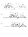
- FIG. 2 is a schematic diagram showing the operation of the wheel loader 1 according to the present embodiment.
- the wheel loader 1 works in a plurality of work modes.
- the work mode includes an excavation work mode in which the excavation target is excavated by the bucket 12 of the work machine 10 and a loading work mode in which the excavated material scooped up by the bucket 12 in the excavation work mode is loaded on the loading target.
- a natural ground DS placed on the ground RS is exemplified as an excavation target.
- a vessel BE (dump body) of a transport vehicle LS capable of traveling on the ground is exemplified.
- a dump truck is illustrated as the transport vehicle LS.
- the wheel loader 1 moves forward toward the natural ground DS in order to excavate the natural ground DS with the bucket 12 in a state where the excavated material is not held in the bucket 12.
- the driver of the wheel loader 1 operates the traveling operation device 40 to move the wheel loader 1 forward and approach the natural ground DS as indicated by an arrow M1 in FIG.
- the three-dimensional measuring device 20 mounted on the wheel loader 1 measures the three-dimensional shape of the natural ground DS.
- the control device 80 calculates the distance from the wheel loader 1 to the natural ground DS as a parameter related to the natural ground DS based on the measurement data of the three-dimensional measuring device 20 so that the natural ground DS is excavated by the bucket 12.
- the work machine 10 is controlled. That is, the control device 80 controls the work implement 10 so that the tip portion 12B and the bottom surface portion of the bucket 12 are in contact with the ground RS while the wheel loader 1 is moving forward so as to approach the natural ground DS. .
- the wheel loader 1 After the bucket 12 enters the natural ground DS and the natural ground DS is excavated by the bucket 12 and the excavated material is skimmed into the bucket 12, the wheel loader 1 is in a state where the excavated material is held in the bucket 12, Go backwards away from Jiyama DS.
- the driver of the wheel loader 1 operates the traveling operation device 40 to move the wheel loader 1 backward and away from the natural ground DS as indicated by an arrow M2 in FIG.
- the loading operation mode is performed.
- the wheel loader 1 moves forward toward the transport vehicle LS to load the excavated material excavated by the bucket 12 while the excavated material is held in the bucket 12.
- the driver of the wheel loader 1 operates the traveling operation device 40 to move the wheel loader 1 forward while turning and approach the transport vehicle LS as indicated by an arrow M3 in FIG.
- the three-dimensional measuring device 20 mounted on the wheel loader 1 measures the three-dimensional shape of the transport vehicle LS.
- the control device 80 calculates the distance from the wheel loader 1 to the transport vehicle LS as a parameter related to the transport vehicle LS based on the measurement data of the three-dimensional measurement device 20, and the excavated matter held in the bucket 12 is transported by the transport vehicle.
- the work machine 10 is controlled so as to be loaded on the LS vessel BE. That is, the control device 80 controls the work implement 10 so that the boom 11 is raised while the wheel loader 1 is moving forward so as to approach the transport vehicle LS. After the boom 11 is raised and the bucket 12 is disposed above the vessel BE, the control device 80 controls the work machine 10 so that the bucket 12 tilts. As a result, the excavated material is discharged from the bucket 12 and loaded onto the vessel BE.
- the wheel loader 1 moves backward away from the transport vehicle LS in a state where the excavated material is not held in the bucket 12.
- the driver operates the traveling operation device 40 to move the wheel loader 1 backward and away from the transport vehicle LS as indicated by an arrow M4 in FIG.
- the driver and the control device 80 repeat the above operation until the vessel BE is fully loaded with excavated material.
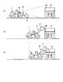
- FIG. 3 is a schematic diagram showing an excavation work mode of the wheel loader 1 according to the present embodiment.
- the driver of the wheel loader 1 operates the traveling operation device 40 to move the wheel loader 1 forward and approach the natural ground DS.
- the three-dimensional measuring device 20 mounted on the wheel loader 1 measures the three-dimensional shape of the natural ground DS.
- the control device 80 specifies the position of the boundary DP between the ground RS and the natural ground DS based on the measurement data of the three-dimensional measurement device 20.
- the control device 80 relates to the natural ground DS based on the measurement data of the three-dimensional measuring device 20 in a state where the wheel loader 1 is moving forward so as to approach the natural ground DS.
- the distance between the tip 12B of the bucket 12 and the boundary DP is calculated.
- the control device 80 lowers the boom 11 and controls the angle of the bucket 12 so that the tip end portion 12B of the bucket 12 approaches the boundary DP based on the measurement data of the three-dimensional measurement device 20.
- the tip 12B of the bucket 12 is inserted from the boundary DP into the natural ground DS.
- the natural ground DS is excavated by the bucket 12, and the bucket 12 can scoop up the excavated material.
- FIG. 4 is a schematic diagram showing a loading operation mode of the wheel loader 1 according to the present embodiment.
- the driver of the wheel loader 1 operates the travel operation device to advance the wheel loader 1 to approach the transport vehicle LS.
- the three-dimensional measuring device 20 mounted on the wheel loader 1 measures the three-dimensional shape of the front surface of the transport vehicle LS.
- the control device 80 detects the distance between the tip 12B of the bucket 12 and the transport vehicle LS and the height of the upper end of the vessel BE as parameters relating to the natural ground DS based on the measurement data of the three-dimensional measurement device 20.
- the height of the upper end portion of the vessel BE is a distance from the ground RS of the approximately horizontal upper end portion on the side wall surface when the vessel BE is viewed from the side as shown in FIG.
- the control device 80 is configured such that the bucket 12 is a vessel based on the measurement data of the three-dimensional measurement device 20 in a state where the wheel loader 1 is moving forward so as to approach the transport vehicle LS.
- the boom 11 is raised while controlling the angle of the bucket 12 so that the excavated matter held in the bucket 12 is not spilled from the bucket 12 so as to be disposed above the upper end of the BE.
- the control device 80 controls the work machine 10 so that the bucket 12 tilts. . As a result, the excavated material is discharged from the bucket 12 and loaded onto the vessel BE.
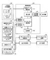
- FIG. 5 is a functional block diagram showing the control device 80 of the wheel loader 1 according to the present embodiment.
- the control device 80 includes a computer system.
- the work device 10 the three-dimensional measuring device 20, the excavated matter determination sensor 51, the rotation sensor 52, and the traveling operation device 40 are connected to the control device 80.
- the control device 80 includes a measurement data acquisition unit 81, a storage unit 82, an excavated matter determination unit 83, a forward / reverse determination unit 84, an algorithm selection unit 85, a calculation unit 86, and a work implement control unit 87. .
- the measurement data acquisition unit 81 acquires measurement data of the three-dimensional measurement apparatus 20.
- the storage unit 82 stores a plurality of algorithms for processing the measurement data acquired by the measurement data acquisition unit 81.
- the algorithm refers to a procedure, flowchart, technique, or program for outputting predetermined data using the measurement data acquired by the measurement data acquisition unit 81.
- the procedure, method, or program may be different, or the number or type of data to be output may be different.
- the storage unit 82 includes a first algorithm for processing the measurement data of the natural ground DS measured by the stereo camera 22 and a second algorithm for processing the measurement data of the transport vehicle LS measured by the stereo camera 22. Is stored.
- the storage unit 82 includes an algorithm for processing the measurement data of the natural ground DS measured by the laser radar 21 and an algorithm for processing the measurement data of the transport vehicle LS measured by the laser radar 21. It is remembered.
- the algorithm for processing the measurement data of the natural ground DS measured by the laser radar 21 is an example of a first algorithm, and the algorithm for processing the measurement data of the transport vehicle LS measured by the laser radar 21 is: It is an example of a 2nd algorithm.
- the excavated matter determination unit 83 determines whether or not the bucket 12 holds an excavated item.
- the excavated matter determination sensor 51 outputs detection data to the control device 80.
- the excavated matter determination sensor 51 includes at least one of a weight sensor, a boom cylinder pressure sensor, a boom angle sensor, and a bucket angle sensor.
- the weight sensor can detect at least one of the weight of the bucket 12, the presence / absence of excavated material in the bucket 12, and the weight of the excavated material held in the bucket 12.
- the boom cylinder pressure sensor can detect the pressure of hydraulic oil in the inner space of the boom cylinder 13.
- the boom angle sensor can detect the rotation angle of the boom 11 in the vehicle body coordinate system.
- the bucket angle sensor can detect the rotation angle of the bucket 12 in the vehicle body coordinate system.
- the excavated matter determination unit 83 determines whether or not the bucket 12 holds the excavated item based on the detection data of the excavated matter determination sensor 51.
- the excavated matter determination unit 83 determines whether the bucket 12 holds an excavated item based on at least one detection signal of the weight sensor, the boom cylinder pressure sensor, the boom angle sensor, and the bucket angle sensor. it can.
- the forward / reverse determination unit 84 determines whether the wheel loader 1 is moving forward based on the detection data of the rotation sensor 52.
- the rotation sensor 52 detects the rotation speed and rotation direction of the wheel 5. Note that the forward / reverse determination unit 84 may determine whether or not the wheel loader 1 is moving forward based on an operation signal of the shift lever 41 of the travel operation device 40.
- the algorithm selection unit 85 selects a specific algorithm for processing the measurement data acquired by the measurement data acquisition unit 81 from a plurality of algorithms stored in the storage unit 82 according to the work of the wheel loader 1.
- the work of the wheel loader 1 includes at least one of the work mode of the wheel loader 1 and the work target of the wheel loader 1.
- the algorithm selection unit 85 determines the work mode of the wheel loader 1 based on the determination data of the excavated matter determination unit 83 and the determination data of the forward / reverse determination unit 84, and according to the work mode of the wheel loader 1. Then, a specific algorithm for processing the measurement data acquired by the measurement data acquisition unit 81 is selected from a plurality of algorithms stored in the storage unit 82.
- the wheel loader 1 moves forward toward the natural ground DS in a state where the excavated material is not held in the bucket 12.
- the wheel loader 1 moves forward toward the transport vehicle LS while the excavated material is held in the bucket 12.
- the algorithm selection unit 85 moves forward toward the natural ground DS so that the wheel loader 1 excavates the natural ground DS with the bucket 12 based on the determination data of the excavated matter determination portion 83 and the determination data of the forward / reverse determination portion 84.
- the first algorithm is selected from a plurality of algorithms stored in the storage unit 82.
- the algorithm selection unit 85 determines that the wheel loader 1 is moving forward toward the transport vehicle LS in order to load the excavated material excavated by the bucket 12, the algorithm selection unit 85 stores a plurality of items stored in the storage unit 82. A second algorithm is selected from the algorithms.
- the algorithm selection unit 85 selects a specific algorithm from a plurality of algorithms based on the determination data of the excavated matter determination unit 83 and the determination data of the forward / reverse determination unit 84 without determining the work mode of the wheel loader 1. May be.
- the algorithm selection unit 85 may determine the work mode or select a specific algorithm based on at least the determination data of the excavated matter determination unit 83.
- the calculation unit 86 processes the measurement data based on the algorithm selected by the algorithm selection unit 85, and calculates parameters related to the work target.
- the calculating unit 86 calculates the distance from the wheel loader 1 to the natural ground DS as the parameter related to the natural ground DS.
- the calculation unit 86 processes the measurement data acquired by the measurement data acquisition unit 81 based on the first algorithm selected by the algorithm selection unit 85, and calculates the distance from the wheel loader 1 to the natural ground DS.
- the calculation part 86 calculates the distance from the wheel loader 1 to the conveyance vehicle LS as a parameter regarding the conveyance vehicle LS, when the 2nd algorithm for calculating the parameter regarding the conveyance vehicle LS is selected.
- the calculation unit 86 processes the measurement data acquired by the measurement data acquisition unit 81 based on the second algorithm selected by the algorithm selection unit 85, and calculates the distance from the wheel loader 1 to the transport vehicle LS.
- the calculation unit 86 may calculate the repose angle of the natural mountain DS as a parameter related to the natural mountain DS in addition to the distance from the wheel loader 1 to the natural mountain DS.
- the parameters relating to the natural mountain DS are the distance from the wheel loader 1 to the natural mountain DS, the angle of repose of the natural mountain DS, the quality of the rock of the natural mountain DS, the granularity of the rock soil constituting the natural mountain DS, It includes at least one of the height of the natural mountain DS, the shape of the natural mountain DS, and the volume of the natural mountain DS.
- the calculation unit 86 may calculate the height of the vessel BE of the transport vehicle LS as a parameter related to the transport vehicle LS.
- the parameters related to the transport vehicle LS include the distance from the wheel loader 1 to the transport vehicle LS, the height of the vessel BE of the transport vehicle LS, the total length of the transport vehicle LS, the total length of the inlet of the vessel BE, and the vessel BE. Including at least one of the heights of the rock that protrudes from the top of the rock.
- the calculation unit 86 processes the measurement data of the natural ground DS based on the first algorithm. Then, the distance from the wheel loader 1 to the natural ground DS is calculated.
- the calculation unit 86 processes the measurement data of the transport vehicle LS based on the second algorithm. Then, the distance from the wheel loader 1 to the transport vehicle LS is calculated.
- the distance from the wheel loader 1 to the natural ground DS is the distance from the wheel loader 1 to the boundary DP between the natural ground DS and the ground RS, and the distance between the tip 12B of the bucket 12 of the wheel loader 1 and the natural ground DS and the ground RS. Includes distance to boundary DP.
- the distance from the wheel loader 1 to the transport vehicle LS is the distance from the wheel loader 1 to the vessel BS, and the distance from the wheel loader 1 to the transport vehicle LS is from the tip 12B of the bucket 12 of the wheel loader 1 to the front of the vessel BS. Includes the distance to the side surface.
- the work machine control unit 87 controls the operation of the work machine 10 based on the distance to the work target calculated by the calculation unit 86.
- the work implement control unit 87 may control the operation of the work implement 10 based on the angle of repose of the natural ground DS calculated by the calculation unit 86 or the height of the vessel BE.
- the control of the operation of the work machine 10 includes the control of the operation of at least one of the boom cylinder 13 and the bucket cylinder 14.
- the wheel loader 1 includes a hydraulic pump (not shown), a boom control valve (not shown) that controls the flow rate and direction of hydraulic oil supplied from the hydraulic pump to the boom cylinder 13, and hydraulic oil supplied to the bucket cylinder 14 from the hydraulic pump.
- a bucket control valve (not shown) for controlling the flow rate and direction.
- the work implement control unit 87 outputs a control signal to the boom control valve to control the flow rate and direction of the hydraulic oil supplied to the boom cylinder 13, so that the boom 11 is raised, lowered, and raised.
- the speed and the operation speed of the lowering operation can be controlled.
- the work machine control unit 87 outputs a control signal to the bucket control valve, and controls the flow rate and direction of the hydraulic oil supplied to the bucket cylinder 14, so that the dump operation, tilt operation, and dump operation of the bucket 12 are performed. It is possible to control the operation speed and the tilt operation speed.
- the wheel loader 1 includes a transmission control unit 88 and a travel control unit 89.
- the transmission control unit 88 controls the operation of the transmission device 30 based on the operation of the traveling operation device 40 by the driver of the wheel loader 1. Control of the operation of the transmission device 30 includes shift change control.
- the traveling control unit 89 controls the operation of the traveling device 4 based on the operation of the traveling operation device 40 by the driver of the wheel loader 1.
- the travel control unit 89 outputs an operation command including an accelerator command for operating the drive device 4A, a brake command for operating the brake device 4B, and a steering command for operating the steering device 4C.
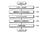
- FIG. 6 is a flowchart showing a method for controlling the wheel loader 1 according to the present embodiment, and shows a method for switching work modes.
- FIG. 6 shows a process in which the stereo camera 22 is used as the three-dimensional measurement apparatus 20.
- the wheel loader 1 is as indicated by the arrow M ⁇ b> 1 in FIG. 2 in a state where no excavated material is held in the bucket 12.
- the vehicle advances toward the natural ground DS.
- the excavated matter determination unit 83 can determine based on the detection data of the excavated matter determination sensor 51 that the bucket 12 does not hold the excavated item.
- the forward / reverse determination unit 84 can determine that the wheel loader 1 is moving forward based on the detection data of the rotation sensor 52.
- the algorithm selection unit 85 is configured so that the wheel loader 1 uses the bucket 12 and the natural ground DS in a state where no excavation is held in the bucket 12. It can be determined that the vehicle is moving forward toward the natural ground DS in order to excavate (step S1).
- the algorithm selection unit 85 determines that the wheel loader 1 is moving forward toward the natural ground DS in order to excavate the natural ground DS with the work machine 10.
- the algorithm selection unit 85 uses a plurality of algorithms stored in the storage unit 82.
- a first algorithm is selected (step S2).
- the calculation unit 86 processes the measurement data of the natural ground DS measured by the stereo camera 22 based on the first algorithm selected by the algorithm selection unit 85, and calculates the distance from the wheel loader 1 to the natural ground DS. To do.
- the wheel loader 1 After the natural ground DS is excavated by the bucket 12 and the excavated material is held in the bucket 12, the wheel loader 1 is in a state where the excavated material is held in the bucket 12, as indicated by the arrow M2 in FIG. Go backwards away from Jiyama DS.
- the loading operation mode is performed.
- the wheel loader 1 holds the excavated material in the bucket 12 and loads the excavated material excavated by the bucket 12 as indicated by an arrow M3 in FIG. Move forward toward.
- the excavated matter determination unit 83 can determine that the bucket 12 holds the excavated item based on the detection data of the excavated matter determination sensor 51.
- the forward / reverse determination unit 84 can determine that the wheel loader 1 is moving forward based on the detection data of the rotation sensor 52.
- the algorithm selection unit 85 Based on the determination data of the excavated matter determination unit 83 and the determination data of the forward / reverse determination unit 84, the algorithm selection unit 85 has excavated the wheel loader 1 by the bucket 12 while the excavated item is held in the bucket 12. It can be determined that the vehicle is moving forward toward the vessel BE of the transport vehicle LS to load the excavated material (step S3).
- the algorithm selection unit 85 is stored in the storage unit 82 when it is determined that the wheel loader 1 is moving forward toward the vessel BE of the transport vehicle LS in order to load the excavated material excavated by the work implement 10.
- a second algorithm is selected from a plurality of algorithms (step S4).
- the calculation unit 86 processes the measurement data of the transport vehicle LS measured by the three-dimensional measurement device 20 based on the second algorithm selected by the algorithm selection unit 85, and the distance from the wheel loader 1 to the transport vehicle LS. Is calculated.
- the wheel loader 1 is removed from the transport vehicle LS as indicated by an arrow M4 in FIG. Move backward to leave.
- the first algorithm when the laser radar 21 is used is selected at step S2
- the second algorithm when the laser radar 21 is used at step S5. Is selected.
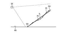
- FIG. 7 is a flowchart illustrating a method for controlling the wheel loader 1 according to the present embodiment, and illustrates a method for processing measurement data of the natural ground DS by the stereo camera 22 based on the first algorithm.
- the process shown in FIG. 7 corresponds to the subroutine of step S2 described with reference to FIG.
- the stereo camera 22 measures the natural ground DS.
- the measurement data acquisition unit 81 acquires measurement data of the stereo camera 22 that measured the natural ground DS from the stereo camera 22 (step S201).
- FIG. 8 is a schematic diagram illustrating a control method of the wheel loader 1 according to the present embodiment, and schematically illustrates a measurement method using the stereo camera 22. As shown in FIG. 8, the stereo camera 22 measures the distance from each of a plurality of measurement points PI on the surface of the natural ground DS.
- the position of the slope of the natural mountain DS is defined in the vehicle body coordinate system of the wheel loader 1.
- the installation position of the stereo camera 22 in the vehicle body coordinate system is known data derived from the design data of the wheel loader 1.
- the calculation unit 86 calculates distances from the stereo camera 22 in the vehicle body coordinate system to a plurality of measurement points PI on the slope of the natural mountain DS.
- the position of the slope of the natural ground DS is defined by the distance from the stereo camera 22 to the slope of the natural ground DS in the vehicle body coordinate system.
- the calculation unit 86 calculates the three-dimensional shape of the natural ground DS based on the distance to each of the plurality of measurement points PI on the surface of the natural ground DS (step S202).
- the calculation unit 86 calculates the distance from the wheel loader 1 to the natural ground DS based on the first algorithm.
- the calculation unit 86 performs straight line fitting on a plurality of measurement points PI and calculates a virtual straight line IL based on the plurality of measurement points PI.
- the straight line IL indicates the estimated shape of the slope of the natural mountain DS. That is, the calculation unit 86 performs straight line fitting on the plurality of measurement points PI, and calculates the position of the slope of the natural mountain DS (step S203).
- the calculating unit 86 calculates the position of the ground RS based on the ground contact surface of the tire 6 (step S204).
- the position of the contact surface of the tire 6 in the vehicle body coordinate system is known data derived from the design data of the wheel loader 1.
- the position of the ground RS in the vehicle body coordinate system is specified by the contact surfaces of at least three of the four tires 6.
- the calculation unit 86 may specify the position of the ground RS based on detection data of an inertial measurement device (IMU: Inertial Measurement Unit) or an inclination sensor. Further, when the ground RS is arranged in the measurement range by the stereo camera 22, the position of the ground RS may be calculated based on the measurement data of the stereo camera 22. Further, in the case where the ground RS is arranged in the measurement range by the stereo camera 22, when the position of the ground RS is specified based on the ground contact surface of the tire 6, the position data of the measurement point PI of the stereo camera 22 on the ground RS is removed. May be. In addition, when removing the position data of the measurement point PI, a height threshold value may be set, and the position data of the measurement point PI may be removed based on the height threshold value.
- IMU Inertial Measurement Unit
- the calculation unit 86 calculates the position of the boundary DP between the slope of the natural ground DS and the ground RS (step S205).
- the calculation unit 86 calculates the distance from the stereo camera 22 to the boundary DP or the distance from the distal end portion 12B of the work machine 10 to the boundary DP (step S206). In addition to the distance from the stereo camera 22 to the boundary DP, the calculation unit 86 uses the installation position of the stereo camera 22 in the vehicle body coordinate system, the installation position of the work machine 10, the dimensions of the work machine 10, the angle of the work machine 10, and the like. Thus, the distance from the tip 12B of the work machine 10 to the boundary DP is calculated.
- the work machine control unit 87 controls the work machine 10 based on the distance to the boundary DP calculated by the calculation unit 86 (step S207).
- the processing by the first algorithm specifies the three-dimensional shape of the natural mountain DS from the measurement data of the stereo camera 22, specifies the slope of the natural mountain DS, and specifies the position of the boundary DP. And calculating the distance from the wheel loader 1 to the boundary DP.
- the work implement control unit 87 reaches the boundary DP calculated by the calculation unit 86 in a state where the wheel loader 1 is moving forward so as to approach the natural ground DS. Based on this distance, the boom 11 can be lowered and the angle of the bucket 12 can be controlled so that the tip 12B of the bucket 12 approaches the boundary DP.
- the tip 12B of the bucket 12 is inserted from the boundary DP into the natural ground DS.
- the natural ground DS is excavated by the bucket 12, and the bucket 12 can scoop up the excavated material.
- FIG. 9 is a flowchart illustrating a method for controlling the wheel loader 1 according to the present embodiment, and illustrates a method for processing measurement data of the transport vehicle LS by the stereo camera 22 based on the second algorithm.
- the process shown in FIG. 9 corresponds to the subroutine of step S4 described with reference to FIG.
- the stereo camera 22 measures the transport vehicle LS.
- the measurement data acquisition unit 81 acquires measurement data of the stereo camera 22 that measures the transport vehicle LS from the stereo camera 22 (step S401).
- Stereo camera 22 measures the distance from each of a plurality of measurement points PI on the surface of transport vehicle LS.
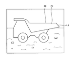
- FIG. 10 is a diagram illustrating an example of image data including the transport vehicle LS acquired by the stereo camera 22 according to the present embodiment.
- FIG. 10 only one measurement point PI (point data) is shown, but a measurement point PI is set for each pixel of the image data shown in FIG.
- the stereo camera 22 can obtain a distance image by performing stereo processing on the image data.
- the calculation unit 86 calculates the distances from the stereo camera 22 in the vehicle body coordinate system to the plurality of measurement points PI on the surface of the transport vehicle LS captured in each pixel based on the measurement data (image data) of the stereo camera 22.
- the position of the surface of the transport vehicle LS is defined by the distance from the stereo camera 22 to the surface of the transport vehicle LS in the vehicle body coordinate system.
- the calculation unit 86 calculates the three-dimensional shape of the transport vehicle LS based on the distance to each of the plurality of measurement points PI on the surface of the transport vehicle LS (Step S402).
- the calculation unit 86 creates a histogram indicating the relationship between the distance from the stereo camera 22 and the number of data of the measurement point PI indicating the distance (step S403).
- FIG. 11 is a schematic diagram showing a histogram showing the relationship between the distance from the stereo camera 22 to the measurement point PI and the number of data of the measurement point PI existing at each distance.
- the image data shown in FIG. 10 includes measurement objects other than the transport vehicle LS such as the ground, for example, as shown in FIG. 11, histogram data exists over a wide range.
- the ratio of the area of the transport vehicle LS is large. Therefore, in the histogram, a peak appears in the distance from the stereo camera 22 to the measurement point PI of the transport vehicle LS.
- the calculation unit 86 determines that the distance at which the peak stands is the distance from the stereo camera 22 to the transport vehicle LS.
- the calculation part 86 calculates the distance from the wheel loader 1 to the transport vehicle LS based on a histogram (step S404).
- the work machine control unit 87 controls the work machine 10 based on the distance to the transport vehicle LS calculated by the calculation unit 86 (step S405).
- the processing by the first algorithm creates a histogram indicating the relationship between the distance from the stereo camera 22 and the number of data of the measurement points PI from the measurement data of the stereo camera 22. It includes specifying the distance at which the peak stands as the distance to the transport vehicle LS, and calculating the distance from the wheel loader 1 to the transport vehicle LS.
- the work machine control unit 87 is the transport vehicle LS calculated by the calculation unit 86 in a state where the wheel loader 1 is moving forward so as to approach the transport vehicle LS.
- the angle of the bucket 12 is adjusted so that the excavated material held in the bucket 12 does not spill from the bucket 12 so that the bucket 12 is disposed above the upper end of the vessel BE.
- the boom 11 can be raised while being controlled. After the boom 11 is raised and the bucket 12 is disposed above the vessel BE, the work implement control unit 87 controls the work implement 10 so that the bucket 12 tilts. As a result, the excavated material is discharged from the bucket 12 and loaded onto the vessel BE.
- the stereo camera 22 was used as the three-dimensional measuring apparatus 20, and the example by which the process by a 1st algorithm and the process by a 2nd algorithm were selected according to work mode was demonstrated.
- the laser radar 21 is used as the three-dimensional measuring device 20.
- processing by the first algorithm that is adapted to the laser radar 21 and processing by the second algorithm that is adapted to the laser radar 21 are selected according to the work mode.
- the algorithm for processing the measurement data of the three-dimensional measurement apparatus 20 is switched based on the work mode of the wheel loader 1. Thereby, even if the work object changes according to the work mode, an appropriate algorithm is selected according to the work object, and the distance from the wheel loader 1 to the work object is calculated based on the selected algorithm.
- the measurement object of the three-dimensional measuring device 20 may have a large difference in shape, for example, a natural mountain DS and a transport vehicle LS. Further, information necessary for controlling the work machine 10 varies depending on the work target. For example, when the work target is the natural ground DS, the repose angle of the natural ground DS or the position of the boundary DP is required in the control of the work machine 10. When the work target is the transport vehicle LS, the distance to the vessel BE and the height of the vessel BE are required in the control of the work machine 10. At the work site, the three-dimensional measurement apparatus 20 sequentially measures work objects having different shapes or necessary information.
- the work mode of the wheel loader 1 is determined, and an algorithm for processing measurement data is selected according to the work mode. Therefore, even if the work target is switched, the distance DS to the measurement target can be calculated with high accuracy. That is, when a different algorithm is selected by the algorithm selection unit 85, the calculation unit 86 can calculate and output parameters related to different work targets.
- the wheel loader 1 moves forward in a state where the excavated material is not held in the bucket 12 (see arrow M ⁇ b> 1), and the excavated material is held in the bucket 12.
- Backward movement operation (see arrow M2), forward movement operation with the excavated object held in the bucket 12 (see arrow M3), and reverse movement with the excavation object not held in the bucket 12
- the operation (see arrow M4) is repeated. Therefore, the algorithm selection unit 85 selects an appropriate algorithm corresponding to the work mode from a plurality of algorithms stored in the storage unit 82 based on the determination data of the excavated matter determination unit 83 and the determination data of the forward / reverse determination unit 84. Can be selected.
- the distance from the wheel loader 1 to the natural ground DS includes the distance from the wheel loader 1 to the boundary DP between the natural ground DS and the ground RS.
- the control device 80 lowers the boom 11 based on the measurement data of the three-dimensional measurement device 20 so that the tip portion 12B of the bucket 12 approaches the boundary DP. While operating, the angle of the bucket 12 can be controlled.
- the distance from the wheel loader 1 to the transport vehicle LS includes the distance from the wheel loader 1 to the front surface of the transport vehicle LS.
- the control device 80 is configured so that the bucket 12 is disposed above the upper end portion of the vessel BE based on the measurement data of the three-dimensional measurement device 20, and The boom 11 can be raised while controlling the angle of the bucket 12 so that the excavated matter held in the bucket 12 does not spill from the bucket 12.
- the control device 80 can control the work implement 10 so that the bucket 12 tilts after the boom 11 is raised and the bucket 12 is disposed above the vessel BE.
- FIG. 12 is a block diagram illustrating an example of a computer system 1000.
- the control device 80 described above includes a computer system 1000.
- the computer system 1000 includes a processor 1001 such as a CPU (Central Processing Unit), a main memory 1002 including a nonvolatile memory such as a ROM (Read Only Memory) and a volatile memory such as a RAM (Random Access Memory), A storage 1003 and an interface 1004 including an input / output circuit are included.
- the functions of the control device 80 described above are stored in the storage 1003 as a program.
- the processor 1001 reads out the program from the storage 1003, expands it in the main memory 1002, and executes the above-described processing according to the program. Note that the program may be distributed to the computer system 1000 via a network.
- the computer system 1000 including the control device 80 acquires measurement data of the three-dimensional measurement device 20 that is mounted on the wheel loader 1 and measures the three-dimensional shape of the work target, and obtains measurement data according to the work of the wheel loader 1. It is possible to perform selection of a specific algorithm to be processed and processing of measurement data based on the selected algorithm to calculate a parameter relating to a work target.
- both the laser radar 21 and the stereo camera 22 are provided in the wheel loader 1 as the three-dimensional measuring device 20.
- One of the laser radar 21 and the stereo camera 22 may be provided in the wheel loader 1.
- the three-dimensional measuring device 20 is not limited to the laser radar 21 and the stereo camera 22 as long as it can measure the three-dimensional shape of the work target and the relative position with the work target. Even when an arbitrary three-dimensional measuring device 20 is used, an algorithm for processing the measurement data of the natural ground DS and an algorithm for processing the measurement data of the transport vehicle LS are selected, so that the work target is selected. Parameters can be calculated.
- the work site where the wheel loader 1 performs work may be a mining site, a construction site, or a construction site.
- the wheel loader 1 may be used for snow removal work, may be used for work in the agriculture and livestock industry, and may be used for work in forestry.
- the work target is not limited to the excavation target and the loading target, and may include a banking target, a leveling target, and a soil removal target, for example.
- the work modes are not limited to the excavation work mode and the loading work mode, and may include, for example, a banking work mode, a leveling work mode, a soil removal work mode, a snow removal work mode, and a standby mode.
- the calculation unit 86 calculates the distance from the wheel loader 1 to the natural mountain DS and the angle of repose of the natural mountain DS as parameters relating to the natural mountain DS.
- the calculation unit 86 may calculate another parameter related to the natural ground DS.
- the calculation unit 86 calculates the distance from the wheel loader 1 to the transport vehicle LS and the height of the vessel BE as parameters applied to the transport vehicle LS.
- the calculation unit 86 may calculate another parameter related to the transport vehicle LS.
- the bucket 12 may have a plurality of blades or a straight blade edge.
- the work member connected to the tip of the boom 11 may not be the bucket 12 but may be a snow plow or snow bucket used for snow removal work, or a bale grab or used for work in the agriculture and livestock industry. It may be a fork or a fork or bucket used in forestry operations.
- the work machine is not limited to a wheel loader, and the control device 80 and the control method described in the above embodiment can be applied to a work machine having a work machine such as a hydraulic excavator or a bulldozer.
- the first work mode is the excavation work mode
- the second work mode is the loading work mode.
- the work mode is not limited to the excavation work mode and the loading work mode.
- the work mode is the two work modes of the first work mode and the second work mode, but may be three or more work modes.
- the measurement device mounted on the wheel loader 1 is the three-dimensional measurement device 20, and the measurement data acquired by the measurement data acquisition unit 81 is three-dimensional data indicating the three-dimensional shape of the work target.
- the measuring device not only the three-dimensional measuring device 20 that measures a work target, but also a camera that is a photo measuring device that photographs the work target, and a position measuring device that measures the position of the work target are mounted on the wheel loader 1.
- the measuring device may include the above-described excavated matter determination sensor 51.
- the measurement data acquired by the measurement data acquisition unit 81 is not only the three-dimensional data of the work target, but also the image data of the work target photographed by the camera, the position data of the work target measured by the position measurement device, and It includes at least one of detection data of the excavated matter determination sensor 51.
- the calculation unit 86 calculates the distance from the tip 12B of the bucket 12 to the work target as the distance from the wheel loader 1 to the work target.
- the calculation unit 86 may calculate a distance from an arbitrary part (for example, a bottom surface part) of the bucket 12 to the work target, or may calculate a distance from an arbitrary part of the work machine 10 to the work target. The distance from an arbitrary part of the vehicle body 2 to the work target may be calculated.
- the algorithm selection unit 85 determines the work mode of the wheel loader 1 or selects a specific algorithm based on the determination data of the excavated matter determination unit 83 and the determination data of the forward / reverse determination unit 84. I decided to do it.
- the algorithm selection unit 85 may perform work mode determination or algorithm selection based on other data different from the determination data of the excavated matter determination unit 83 and the determination data of the forward / reverse determination unit 84.
- the three-dimensional data of the work object which is measurement data of the three-dimensional measuring device 20, the detection data of the excavated object determination sensor 51, the image data of the work object imaged by the camera mounted on the wheel loader 1 And at least one of the position data of the work object measured by the position measuring device mounted on the wheel loader 1 is exemplified.
- the algorithm selection unit 85 has determined the work mode.
- the algorithm selection unit 85 determines a work target by some method and selects an algorithm according to the determined work target. May be.
- a method for determining the work target the three-dimensional data of the work target that is measurement data of the three-dimensional measuring device 20, the detection data of the excavated object determination sensor 51, and the work target imaged by the camera mounted on the wheel loader 1
- a method for determining a work target using at least one of image data and position data of the work target measured by a position measurement device mounted on the wheel loader 1 is exemplified.
- the work of the wheel loader 1 is a concept including at least one of the work mode of the wheel loader 1 and the operation of the wheel loader 1 with respect to the work target.
- the algorithm selection unit 85 can select an algorithm according to the operation of the wheel loader 1.
- the algorithm selection unit 85 can select an algorithm according to the work mode of the wheel loader 1 and can select an algorithm according to the work target of the wheel loader 1.
- the work mode includes a state in which the wheel loader 1 performs a predetermined operation.
- the work mode includes a work mode including a plurality of work modes in addition to a single work mode such as the excavation work mode or the loading work mode as described above.
- the above-mentioned excavation work mode M1 As a work mode that includes a plurality of work modes, the above-mentioned excavation work mode M1, the mode M2 that leaves the natural ground DS, the loading work mode M3, and the mode M4 that leaves the transport vehicle LS include a series of work modes “V shape” “Working mode” is exemplified.
- the transmission device 30 and the travel operation device 40 of the wheel loader 1 are driven by a driver's operation.
- the transmission control unit 88 and the travel control unit 89 may automatically control the transmission device 30 and the travel device 4.
- the transmission control unit 88 and the travel control unit 89 can control the transmission device 30 and the travel device 4 based on the distance from the wheel loader 1 calculated by the calculation unit 86 to the work target.
- SYMBOLS 1 Wheel loader (work machine), 2 ... Vehicle body, 2F ... Vehicle body front part, 2R ... Vehicle body rear part, 3 ... Driver's cab, 4 ... Traveling device, 4A ... Drive device, 4B ... Brake device, 4C ... Steering device, 5 Wheel, 5F ... Front wheel, 5R ... Rear wheel, 6 ... Tire, 6F ... Front tire, 6R ... Rear tire, 9 ... Joint mechanism, 10 ... Work machine, 11 ... Boom, 12 ... Bucket, 12B ... Tip, 13 DESCRIPTION OF SYMBOLS ... Boom cylinder, 14 ... Bucket cylinder, 15 ... Bell crank, 16 ...
Landscapes
- Engineering & Computer Science (AREA)
- Mining & Mineral Resources (AREA)
- Civil Engineering (AREA)
- General Engineering & Computer Science (AREA)
- Structural Engineering (AREA)
- Mechanical Engineering (AREA)
- Operation Control Of Excavators (AREA)
Abstract
作業機械の制御装置は、作業機を有する作業機械に搭載され作業対象を計測する計測装置の計測データを取得する計測データ取得部と、作業機械の作業に応じて計測データを処理する特定のアルゴリズムを選択するアルゴリズム選択部と、アルゴリズム選択部により選択されたアルゴリズムに基づいて計測データを処理して、作業対象に関するパラメータを算出する算出部と、を備える。
Description
本発明は、作業機械の制御装置及び作業機械の制御方法に関する。
作業現場において作業機械が使用される。掘削対象及び積込対象までの距離を求めるための計測器を備える自動掘削機の一例が特許文献1に開示されている。
作業機械による作業の自動化を実現する場合、作業対象に関するパラメータを取得することが要望される。
本発明の態様は、作業対象に関するパラメータを取得することを目的とする。
本発明の態様に従えば、作業機を有する作業機械に搭載され作業対象を計測する計測装置の計測データを取得する計測データ取得部と、前記作業機械の作業に応じて前記計測データを処理する特定のアルゴリズムを選択するアルゴリズム選択部と、前記アルゴリズム選択部により選択された前記アルゴリズムに基づいて前記計測データを処理して、前記作業対象に関するパラメータを算出する算出部と、を備える作業機械の制御装置が提供される。
本発明の態様によれば、作業対象に関するパラメータを取得することができる。
以下、本発明に係る実施形態について図面を参照しながら説明するが、本発明はこれに限定されない。以下で説明する実施形態の構成要素は、適宜組み合わせることができる。また、一部の構成要素を用いない場合もある。
[ホイールローダ]
図1は、本実施形態に係る作業機械1の一例を示す側面図である。作業機械1は、作業現場において作業対象に対して所定の作業を実施する。本実施形態においては、作業機械1がアーティキュレート作業機械の一種であるホイールローダ1であることとする。所定の作業は、掘削作業及び積込作業を含む。作業対象は、掘削対象及び積込対象を含む。ホイールローダ1は、掘削対象を掘削する掘削作業、及び掘削作業により掘削した掘削物を積込対象に積み込む積込作業を実施する。積込作業は、掘削物を排出対象に排出する排出作業を含む概念である。掘削対象として、地山、岩山、石炭、及び壁面の少なくとも一つが例示される。地山は、土砂により構成される山であり、岩山は、岩又は石により構成される山である。積込対象として、運搬車両、作業現場の所定エリア、ホッパ、ベルトコンベヤ、及びクラッシャの少なくとも一つが例示される。
図1は、本実施形態に係る作業機械1の一例を示す側面図である。作業機械1は、作業現場において作業対象に対して所定の作業を実施する。本実施形態においては、作業機械1がアーティキュレート作業機械の一種であるホイールローダ1であることとする。所定の作業は、掘削作業及び積込作業を含む。作業対象は、掘削対象及び積込対象を含む。ホイールローダ1は、掘削対象を掘削する掘削作業、及び掘削作業により掘削した掘削物を積込対象に積み込む積込作業を実施する。積込作業は、掘削物を排出対象に排出する排出作業を含む概念である。掘削対象として、地山、岩山、石炭、及び壁面の少なくとも一つが例示される。地山は、土砂により構成される山であり、岩山は、岩又は石により構成される山である。積込対象として、運搬車両、作業現場の所定エリア、ホッパ、ベルトコンベヤ、及びクラッシャの少なくとも一つが例示される。
図1に示すように、ホイールローダ1は、車体2と、運転席が設けられる運転台3と、車体2を支持する走行装置4と、車体2に支持される作業機10と、トランスミッション装置30と、車体2よりも前方の作業対象を計測する三次元計測装置20と、制御装置80とを備える。
車体2は、車体前部2Fと車体後部2Rとを含む。車体前部2Fと車体後部2Rとは、関節機構9を介して屈曲可能に連結される。
運転台3は、車体2に支持される。ホイールローダ1の少なくとも一部は、運転台3に搭乗した運転者によって操作される。
走行装置4は、車体2を支持する。走行装置4は、車輪5を有する。車輪5は、車体2に搭載されているエンジンが発生する駆動力により回転する。タイヤ6が車輪5に装着される。車輪5は、車体前部2Fに装着される2つの前輪5Fと、車体後部2Rに装着される2つの後輪5Rとを含む。タイヤ6は、前輪5Fに装着される前タイヤ6Fと、後輪5Rに装着される後タイヤ6Rとを含む。走行装置4は、地面RSを走行可能である。
以下の説明においては、前輪5Fの回転軸と平行な方向を適宜、車幅方向、と称し、地面RSと接触する前タイヤ6Fの接地面と直交する方向を適宜、上下方向、と称し、車幅方向及び上下方向の両方と直交する方向を適宜、前後方向、と称する。ホイールローダ1の車体2が直進状態で走行するとき、前輪5Fの回転軸と後輪5Rの回転軸とは平行である。
また、以下の説明においては、車幅方向において車体2の中心に近い位置又は方向を適宜、車幅方向の内側又は内方、と称し、車体2の中心から遠い位置又は方向を適宜、車幅方向の外側又は外方、と称する。また、車幅方向において、運転台3の運転席を基準とする一方を適宜、右側又は右方、と称し、右側又は右方の逆側又は逆方向を適宜、左側又は左方、と称する。また、前後方向において、運転台3の運転席を基準として作業機10に近い位置又は方向を適宜、前側又は前方、と称し、前側又は前方の逆側又は逆方向を適宜、後側又は後方、と称する。また、上下方向において前タイヤ6Fの接地面に近い位置又は方向を適宜、下側又は下方、と称し、下側又は下方の逆側又は逆方向を適宜、上側又は上方、と称する。
車体前部2Fは、車体後部2Rよりも前方に配置される。前輪5F及び前タイヤ6Fは、後輪5R及び後タイヤ6Rよりも前方に配置される。前輪5F及び前タイヤ6Fは、車体2の車幅方向の両側に配置される。後輪5R及び後タイヤ6Rは、車体2の車幅方向の両側に配置される。車体前部2Fは、車体後部2Rに対して左右に屈曲する。
走行装置4は、駆動装置4Aと、ブレーキ装置4Bと、操舵装置4Cとを有する。駆動装置4Aは、ホイールローダ1を加速させるための駆動力を発生する。駆動装置4Aは、ディーゼルエンジンのような内燃機関を含む。駆動装置4Aで発生した駆動力がトランスミッション装置30を介して車輪5に伝達され、車輪5が回転する。ブレーキ装置4Bは、ホイールローダ1を減速又は停止させるための制動力を発生する。操舵装置4Cは、ホイールローダ1の走行方向を調整可能である。ホイールローダ1の走行方向は、車体前部2Fの向きを含む。操舵装置4Cは、油圧シリンダによって車体前部2Fを屈曲させることによって、ホイールローダ1の走行方向を調整する。
本実施形態において、走行装置4は、運転台3に搭乗した運転者によって操作される。作業機10は、制御装置80に制御される。走行装置4を操作する走行操作装置40が運転台3に配置される。運転者は、走行操作装置40を操作して、走行装置4を作動させる。走行操作装置40は、アクセルペダル、ブレーキペダル、ステアリングレバー、及び前後進を切り換えるためのシフトレバー41を含む。アクセルペダルが操作されることにより、ホイールローダ1の走行速度が増大する。ブレーキペダルが操作されることにより、ホイールローダ1の走行速度が減少したり走行が停止したりする。ステアリングレバーが操作されることにより、ホイールローダ1が旋回する。シフトレバー41が操作されることにより、ホイールローダ1の前進又は後進が切り換えられる。
トランスミッション装置30は、駆動装置4Aで発生した駆動力を車輪5に伝達する。
作業機10は、車体前部2Fに回動可能に連結されるブーム11と、ブーム11に回動可能に連結されるバケット12と、ベルクランク15と、リンク16とを有する。
ブーム11は、ブームシリンダ13が発生する動力によって作動する。ブームシリンダ13が伸縮することにより、ブーム11は上げ動作又は下げ動作する。
バケット12は、刃先を含む先端部12Bを有する作業部材である。バケット12は、前輪5Fよりも前方に配置される。バケット12は、ブーム11の先端部に連結される。バケット12は、バケットシリンダ14が発生する動力によって作動する。バケットシリンダ14が伸縮することにより、バケット12はダンプ動作又はチルト動作する。
バケット12のダンプ動作が実施されることにより、バケット12ですくい上げられた掘削物がバケット12から排出される。バケット12のチルト動作が実施されることにより、バケット12は掘削物をすくい取る。
[三次元計測装置]
三次元計測装置20は、ホイールローダ1に搭載される。三次元計測装置20は、車体前部2Fよりも前方の作業対象を計測する。作業対象は、作業機10による掘削対象、及び作業機10により掘削された掘削物が積み込まれる積込対象を含む。三次元計測装置20は、三次元計測装置20から作業対象の表面の複数の各計測点までの相対位置を計測して、作業対象の三次元形状を計測する。制御装置80は、計測された作業対象の三次元形状に基づいて、作業対象に関するパラメータを算出する。後述するように、作業対象に関するパラメータは、掘削対象までの距離、積込対象までの距離、掘削対象の安息角、及び積込対象の高さの少なくとも一つを含む。
三次元計測装置20は、ホイールローダ1に搭載される。三次元計測装置20は、車体前部2Fよりも前方の作業対象を計測する。作業対象は、作業機10による掘削対象、及び作業機10により掘削された掘削物が積み込まれる積込対象を含む。三次元計測装置20は、三次元計測装置20から作業対象の表面の複数の各計測点までの相対位置を計測して、作業対象の三次元形状を計測する。制御装置80は、計測された作業対象の三次元形状に基づいて、作業対象に関するパラメータを算出する。後述するように、作業対象に関するパラメータは、掘削対象までの距離、積込対象までの距離、掘削対象の安息角、及び積込対象の高さの少なくとも一つを含む。
三次元計測装置20は、レーザ計測装置の一種であるレーザレーダ21と、写真計測装置の一種であるステレオカメラ22とを含む。
[動作]
図2は、本実施形態に係るホイールローダ1の動作を示す模式図である。ホイールローダ1は、複数の作業モードで作業する。作業モードは、作業機10のバケット12で掘削対象を掘削する掘削作業モードと、掘削作業モードによりバケット12ですくい取った掘削物を積込対象に積み込む積込作業モードとを含む。掘削対象として、地面RSに置かれた地山DSが例示される。積込対象として、地面を走行可能な運搬車両LSのベッセルBE(ダンプボディ)が例示される。運搬車両LSとして、ダンプトラックが例示される。
図2は、本実施形態に係るホイールローダ1の動作を示す模式図である。ホイールローダ1は、複数の作業モードで作業する。作業モードは、作業機10のバケット12で掘削対象を掘削する掘削作業モードと、掘削作業モードによりバケット12ですくい取った掘削物を積込対象に積み込む積込作業モードとを含む。掘削対象として、地面RSに置かれた地山DSが例示される。積込対象として、地面を走行可能な運搬車両LSのベッセルBE(ダンプボディ)が例示される。運搬車両LSとして、ダンプトラックが例示される。
掘削作業モードにおいて、ホイールローダ1は、バケット12に掘削物が保持されていない状態で、バケット12で地山DSを掘削するために地山DSに向かって前進する。ホイールローダ1の運転者は、走行操作装置40を操作して、図2の矢印M1で示すように、ホイールローダ1を前進させて地山DSに接近させる。ホイールローダ1に搭載されている三次元計測装置20は、地山DSの三次元形状を計測する。制御装置80は、三次元計測装置20の計測データに基づいて、地山DSに関するパラメータとして、ホイールローダ1から地山DSまでの距離を算出し、バケット12で地山DSが掘削されるように、作業機10を制御する。すなわち、制御装置80は、ホイールローダ1が地山DSに接近するように前進している状態で、バケット12の先端部12B及び底面部が地面RSに接触するように、作業機10を制御する。
バケット12が地山DSに突入して地山DSがバケット12により掘削され、掘削物がバケット12にすくい取られた後、ホイールローダ1は、バケット12に掘削物が保持されている状態で、地山DSから離れるように後進する。ホイールローダ1の運転者は、走行操作装置40を操作して、図2の矢印M2で示すように、ホイールローダ1を後進させて地山DSから離間させる。
次に、積込作業モードが実施される。積込作業モードにおいて、ホイールローダ1は、バケット12に掘削物が保持されている状態で、バケット12により掘削された掘削物を積み込むために運搬車両LSに向かって前進する。ホイールローダ1の運転者は、走行操作装置40を操作して、図2の矢印M3で示すように、ホイールローダ1を旋回させながら前進させて運搬車両LSに接近させる。ホイールローダ1に搭載されている三次元計測装置20は、運搬車両LSの三次元形状を計測する。制御装置80は、三次元計測装置20の計測データに基づいて、運搬車両LSに関するパラメータとして、ホイールローダ1から運搬車両LSまでの距離を算出し、バケット12に保持されている掘削物が運搬車両LSのベッセルBEに積み込まれるように、作業機10を制御する。すなわち、制御装置80は、ホイールローダ1が運搬車両LSに接近するように前進している状態で、ブーム11が上げ動作するように、作業機10を制御する。ブーム11が上げ動作し、バケット12がベッセルBEの上方に配置された後、制御装置80は、バケット12がチルト動作するように、作業機10を制御する。これにより、バケット12から掘削物が排出され、ベッセルBEに積み込まれる。
バケット12から掘削物が排出され、ベッセルBEに積み込まれた後、ホイールローダ1は、バケット12に掘削物が保持されていない状態で、運搬車両LSから離れるように後進する。運転者は、走行操作装置40を操作して、図2の矢印M4で示すように、ホイールローダ1を後進させて運搬車両LSから離間させる。
運転者及び制御装置80は、ベッセルBEに掘削物が満載されるまで、上述の動作を繰り返す。
図3は、本実施形態に係るホイールローダ1の掘削作業モードを示す模式図である。ホイールローダ1の運転者は、走行操作装置40を操作して、ホイールローダ1を前進させて地山DSに接近させる。
図3(A)に示すように、ホイールローダ1に搭載されている三次元計測装置20は、地山DSの三次元形状を計測する。制御装置80は、三次元計測装置20の計測データに基づいて、地面RSと地山DSとの境界DPの位置を特定する。
図3(B)に示すように、制御装置80は、ホイールローダ1が地山DSに接近するように前進している状態で、三次元計測装置20の計測データに基づいて、地山DSに関するパラメータとして、バケット12の先端部12Bと境界DPとの距離を算出する。制御装置80は、三次元計測装置20の計測データに基づいて、バケット12の先端部12Bが境界DPに接近するように、ブーム11を下げ動作させるとともに、バケット12の角度を制御する。
図3(C)に示すように、ホイールローダ1がさらに前進することにより、バケット12の先端部12Bが境界DPから地山DSに挿入される。これにより、地山DSがバケット12により掘削され、バケット12は、掘削物をすくい取ることができる。
図4は、本実施形態に係るホイールローダ1の積込作業モードを示す模式図である。ホイールローダ1の運転者は、走行操作装置を操作して、ホイールローダ1を前進させて運搬車両LSに接近させる。図4(A)に示すように、ホイールローダ1に搭載されている三次元計測装置20は、運搬車両LSの手前側表面の三次元形状を計測する。制御装置80は、三次元計測装置20の計測データに基づいて、地山DSに関するパラメータとして、バケット12の先端部12Bと運搬車両LSとの距離及びベッセルBEの上端部の高さを検出する。ベッセルBEの上端部の高さは、例えば後述する図10のようにベッセルBEを側面視した際の側壁面におけるおよそ水平な上端部の地面RSからの距離である。
図4(B)に示すように、制御装置80は、ホイールローダ1が運搬車両LSに接近するように前進している状態で、三次元計測装置20の計測データに基づいて、バケット12がベッセルBEの上端部よりも上方に配置されるように、且つ、バケット12に保持されている掘削物がバケット12からこぼれないように、バケット12の角度を制御しながら、ブーム11を上げ動作させる。
図4(C)に示すように、ブーム11が上げ動作し、バケット12がベッセルBEの上方に配置された後、制御装置80は、バケット12がチルト動作するように、作業機10を制御する。これにより、バケット12から掘削物が排出され、ベッセルBEに積み込まれる。
[制御装置]
図5は、本実施形態に係るホイールローダ1の制御装置80を示す機能ブロック図である。制御装置80は、コンピュータシステムを含む。
図5は、本実施形態に係るホイールローダ1の制御装置80を示す機能ブロック図である。制御装置80は、コンピュータシステムを含む。
制御装置80に、作業機10、三次元計測装置20、掘削物判定用センサ51、回転センサ52、及び走行操作装置40が接続される。
制御装置80は、計測データ取得部81と、記憶部82と、掘削物判定部83と、前後進判定部84と、アルゴリズム選択部85と、算出部86と、作業機制御部87とを有する。
計測データ取得部81は、三次元計測装置20の計測データを取得する。
記憶部82は、計測データ取得部81により取得された計測データを処理する複数のアルゴリズムを記憶する。アルゴリズムとは、計測データ取得部81により取得された計測データを用いて、所定のデータを出力するための手順、フローチャート、手法、又はプログラムをいう。複数のアルゴリズムに応じて、手順、手法、又はプログラムを異ならせてもよいし、出力されるデータの数又は種類を異ならせてもよい。記憶部82には、ステレオカメラ22で計測された地山DSの計測データを処理するための第1アルゴリズムと、ステレオカメラ22で計測された運搬車両LSの計測データを処理するための第2アルゴリズムとが記憶されている。また、記憶部82には、レーザレーダ21で計測された地山DSの計測データを処理するためのアルゴリズムと、レーザレーダ21で計測された運搬車両LSの計測データを処理するためのアルゴリズムとが記憶されている。レーザレーダ21で計測された地山DSの計測データを処理するためのアルゴリズムは、第1アルゴリズムの一例であり、レーザレーダ21で計測された運搬車両LSの計測データを処理するためのアルゴリズムは、第2アルゴリズムの一例である。
掘削物判定部83は、バケット12が掘削物を保持しているか否かを判定する。掘削物判定用センサ51は、検出データを制御装置80に出力する。掘削物判定用センサ51は、重量センサ、ブームシリンダ圧力センサ、ブーム角度センサ、及びバケット角度センサの少なくとも一つを含む。重量センサは、バケット12の重量、バケット12における掘削物の有無、及びバケット12に保持された掘削物の重量の少なくとも一つを検出することができる。ブームシリンダ圧力センサは、ブームシリンダ13の内部空間の作動油の圧力を検出することができる。ブーム角度センサは、車体座標系におけるブーム11の回動角度を検出することができる。バケット角度センサは、車体座標系におけるバケット12の回動角度を検出することができる。掘削物判定部83は、掘削物判定用センサ51の検出データに基づいて、バケット12が掘削物を保持しているか否かを判定する。掘削物判定部83は、重量センサ、ブームシリンダ圧力センサ、ブーム角度センサ、及びバケット角度センサの少なくとも一つの検出信号に基づいて、バケット12が掘削物を保持しているか否かを判定することができる。
前後進判定部84は、回転センサ52の検出データに基づいて、ホイールローダ1が前進しているか否かを判定する。回転センサ52は、車輪5の回転速度及び回転方向を検出する。なお、前後進判定部84は、走行操作装置40のシフトレバー41の操作信号に基づいて、ホイールローダ1が前進しているか否かを判定してもよい。
アルゴリズム選択部85は、ホイールローダ1の作業に応じて、記憶部82に記憶されている複数のアルゴリズムから、計測データ取得部81により取得された計測データを処理する特定のアルゴリズムを選択する。ホイールローダ1の作業は、ホイールローダ1の作業モード、及びホイールローダ1の作業対象の少なくとも一方を含む。
本実施形態において、アルゴリズム選択部85は、掘削物判定部83の判定データ及び前後進判定部84の判定データに基づいて、ホイールローダ1の作業モードを判定し、ホイールローダ1の作業モードに応じて、記憶部82に記憶されている複数のアルゴリズムから、計測データ取得部81により取得された計測データを処理する特定のアルゴリズムを選択する。
掘削作業モードにおいて、ホイールローダ1は、バケット12に掘削物が保持されていない状態で、地山DSに向かって前進する。積込作業モードにおいて、ホイールローダ1は、バケット12に掘削物が保持されている状態で、運搬車両LSに向かって前進する。アルゴリズム選択部85は、掘削物判定部83の判定データ及び前後進判定部84の判定データに基づいて、ホイールローダ1がバケット12で地山DSを掘削するために地山DSに向かって前進していると判定したときに、記憶部82に記憶されている複数のアルゴリズムから第1アルゴリズムを選択する。また、アルゴリズム選択部85は、ホイールローダ1がバケット12により掘削された掘削物を積み込むために運搬車両LSに向かって前進していると判定したときに、記憶部82に記憶されている複数のアルゴリズムから第2アルゴリズムを選択する。
なお、アルゴリズム選択部85は、ホイールローダ1の作業モードを判定することなく、掘削物判定部83の判定データ及び前後進判定部84の判定データに基づいて、複数のアルゴリズムから特定のアルゴリズムを選択してもよい。アルゴリズム選択部85は、少なくとも掘削物判定部83の判定データに基づいて、作業モードを判定又は特定のアルゴリズムを選択してもよい。
算出部86は、アルゴリズム選択部85により選択されたアルゴリズムに基づいて計測データを処理して、作業対象に関するパラメータを算出する。算出部86は、地山DSに関するパラメータを算出するための第1アルゴリズムが選択されたとき、地山DSに関するパラメータとして、ホイールローダ1から地山DSまでの距離を算出する。算出部86は、アルゴリズム選択部85により選択された第1アルゴリズムに基づいて計測データ取得部81により取得された計測データを処理して、ホイールローダ1から地山DSまでの距離を算出する。また、算出部86は、運搬車両LSに関するパラメータを算出するための第2アルゴリズムが選択されたとき、運搬車両LSに関するパラメータとして、ホイールローダ1から運搬車両LSまでの距離を算出する。算出部86は、アルゴリズム選択部85により選択された第2アルゴリズムに基づいて計測データ取得部81により取得された計測データを処理して、ホイールローダ1から運搬車両LSまでの距離を算出する。
なお、算出部86は、ホイールローダ1から地山DSまでの距離に加え、地山DSに関するパラメータとして、地山DSの安息角を算出してもよい。本実施形態において、地山DSに関するパラメータは、ホイールローダ1から地山DSまでの距離、地山DSの安息角、地山DSの岩土の質、地山DSを構成する岩土の粒度、地山DSの高さ、地山DSの形状、及び地山DSの体積の少なくとも一つを含む。
なお、算出部86は、ホイールローダ1から運搬車両LSまでの距離に加え、運搬車両LSに関するパラメータとして、運搬車両LSのベッセルBEの高さを算出してもよい。本実施形態において、運搬車両LSに関するパラメータは、ホイールローダ1から運搬車両LSまでの距離、運搬車両LSのベッセルBEの高さ、運搬車両LSの全長、ベッセルBEの投入口の全長、及びベッセルBEの上端部から飛び出している岩土の高さの少なくとも一つを含む。
ホイールローダ1の作業モードが掘削作業モードであると判定され、アルゴリズム選択部85により第1アルゴリズムが選択された場合、算出部86は、第1アルゴリズムに基づいて地山DSの計測データを処理して、ホイールローダ1から地山DSまでの距離を算出する。ホイールローダ1の作業モードが積込作業モードであると判定され、アルゴリズム選択部85により第2アルゴリズムが選択された場合、算出部86は、第2アルゴリズムに基づいて運搬車両LSの計測データを処理して、ホイールローダ1から運搬車両LSまでの距離を算出する。
ホイールローダ1から地山DSまでの距離は、ホイールローダ1から地山DSと地面RSとの境界DPまでの距離、およびホイールローダ1のバケット12の先端部12Bから地山DSと地面RSとの境界DPまでの距離を含む。ホイールローダ1から運搬車両LSまでの距離は、ホイールローダ1からベッセルBSまでの距離、およびホイールローダ1から運搬車両LSまでの距離は、ホイールローダ1のバケット12の先端部12BからベッセルBSの手前側表面までの距離を含む。
作業機制御部87は、算出部86により算出された作業対象までの距離に基づいて、作業機10の動作を制御する。作業機制御部87は、算出部86により算出された地山DSの安息角、又はベッセルBEの高さに基づいて、作業機10の動作を制御してもよい。作業機10の動作の制御は、ブームシリンダ13及びバケットシリンダ14の少なくとも一方の動作の制御を含む。ホイールローダ1は、図示しない油圧ポンプと、油圧ポンプからブームシリンダ13に供給される作動油の流量及び方向を制御する図示しないブーム制御弁と、油圧ポンプからバケットシリンダ14に供給される作動油の流量及び方向を制御する図示しないバケット制御弁とを有する。作業機制御部87は、ブーム制御弁に制御信号を出力して、ブームシリンダ13に供給される作動油の流量及び方向を制御することによって、ブーム11の上げ動作、下げ動作、上げ動作の動作速度、及び下げ動作の動作速度を制御することができる。また、作業機制御部87は、バケット制御弁に制御信号を出力して、バケットシリンダ14に供給される作動油の流量及び方向を制御することによって、バケット12のダンプ動作、チルト動作、ダンプ動作の動作速度、及びチルト動作の動作速度を制御することができる。
本実施形態において、ホイールローダ1は、トランスミッション制御部88と、走行制御部89とを有する。
トランスミッション制御部88は、ホイールローダ1の運転者による走行操作装置40の操作に基づいて、トランスミッション装置30の動作を制御する。トランスミッション装置30の動作の制御は、シフトチェンジの制御を含む。
走行制御部89は、ホイールローダ1の運転者による走行操作装置40の操作に基づいて、走行装置4の動作を制御する。走行制御部89は、駆動装置4Aを作動するためのアクセル指令、ブレーキ装置4Bを作動するためのブレーキ指令、及び操舵装置4Cを作動するためのステアリング指令を含む運転指令を出力する。
[作業モードの切換]
図6は、本実施形態に係るホイールローダ1の制御方法を示すフローチャートであって、作業モードの切換方法を示す。なお、図6は、三次元計測装置20としてステレオカメラ22が用いられる処理を示す。
図6は、本実施形態に係るホイールローダ1の制御方法を示すフローチャートであって、作業モードの切換方法を示す。なお、図6は、三次元計測装置20としてステレオカメラ22が用いられる処理を示す。
図2、図3、及び図4を参照して説明したように、掘削作業モードにおいて、ホイールローダ1は、バケット12に掘削物が保持されていない状態で、図2の矢印M1で示したように、バケット12で地山DSを掘削するために地山DSに向かって前進する。
掘削物判定部83は、掘削物判定用センサ51の検出データに基づいて、バケット12が掘削物を保持していないと判定することができる。前後進判定部84は、回転センサ52の検出データに基づいて、ホイールローダ1が前進していると判定することができる。アルゴリズム選択部85は、掘削物判定部83の判定データ及び前後進判定部84の判定データに基づいて、バケット12に掘削物が保持されていない状態で、ホイールローダ1がバケット12で地山DSを掘削するために地山DSに向かって前進していると判定することができる(ステップS1)。
アルゴリズム選択部85は、ホイールローダ1が作業機10で地山DSを掘削するために地山DSに向かって前進していると判定したときに、記憶部82に記憶されている複数のアルゴリズムから第1アルゴリズムを選択する(ステップS2)。
算出部86は、アルゴリズム選択部85により選択された第1アルゴリズムに基づいて、ステレオカメラ22により計測された地山DSの計測データを処理して、ホイールローダ1から地山DSまでの距離を算出する。
地山DSがバケット12により掘削され、掘削物がバケット12に保持された後、ホイールローダ1は、バケット12に掘削物が保持されている状態で、図2の矢印M2で示したように、地山DSから離れるように後進する。
次に、積込作業モードが実施される。積込作業モードにおいて、ホイールローダ1は、バケット12に掘削物が保持されている状態で、図2の矢印M3で示したように、バケット12により掘削された掘削物を積み込むために運搬車両LSに向かって前進する。
掘削物判定部83は、掘削物判定用センサ51の検出データに基づいて、バケット12が掘削物を保持していると判定することができる。前後進判定部84は、回転センサ52の検出データに基づいて、ホイールローダ1が前進していると判定することができる。アルゴリズム選択部85は、掘削物判定部83の判定データ及び前後進判定部84の判定データに基づいて、バケット12に掘削物が保持されている状態で、ホイールローダ1がバケット12により掘削された掘削物を積み込むために運搬車両LSのベッセルBEに向かって前進していると判定することができる(ステップS3)。
アルゴリズム選択部85は、ホイールローダ1が作業機10により掘削された掘削物を積み込むために運搬車両LSのベッセルBEに向かって前進していると判定したときに、記憶部82に記憶されている複数のアルゴリズムから第2アルゴリズムを選択する(ステップS4)。
算出部86は、アルゴリズム選択部85により選択された第2アルゴリズムに基づいて、三次元計測装置20により計測された運搬車両LSの計測データを処理して、ホイールローダ1から運搬車両LSまでの距離を算出する。
バケット12から掘削物が排出され、ベッセルBEに積み込まれた後、ホイールローダ1は、バケット12に掘削物が保持されていない状態で、図2の矢印M4で示したように、運搬車両LSから離れるように後進する。
なお、三次元計測装置20としてレーザレーダ21が用いられる場合、ステップS2においてはレーザレーダ21を用いた場合における第1アルゴリズムが選択され、ステップS5においてはレーザレーダ21を用いた場合における第2アルゴリズムが選択される。
[第1アルゴリズムによる処理]
図7は、本実施形態に係るホイールローダ1の制御方法を示すフローチャートであって、ステレオカメラ22による地山DSの計測データを第1アルゴリズムに基づいて処理する方法を示す。図7に示す処理は、図6を参照して説明したステップS2のサブルーチンに相当する。
図7は、本実施形態に係るホイールローダ1の制御方法を示すフローチャートであって、ステレオカメラ22による地山DSの計測データを第1アルゴリズムに基づいて処理する方法を示す。図7に示す処理は、図6を参照して説明したステップS2のサブルーチンに相当する。
ホイールローダ1が作業機10で地山DSを掘削するために地山DSに向かって前進する掘削作業モードにおいて、ステレオカメラ22は、地山DSを計測する。計測データ取得部81は、ステレオカメラ22から、地山DSを計測したステレオカメラ22の計測データを取得する(ステップS201)。
図8は、本実施形態に係るホイールローダ1の制御方法を示す模式図であって、ステレオカメラ22による計測方法を模式的に示す。図8に示すように、ステレオカメラ22は、地山DSの表面の複数の計測点PIのそれぞれとの距離を計測する。
地山DSの斜面の位置は、ホイールローダ1の車体座標系において規定される。車体座標系におけるステレオカメラ22の設置位置は、ホイールローダ1の設計データから導出される既知データである。算出部86は、車体座標系におけるステレオカメラ22から地山DSの斜面における複数の計測点PIまでの距離を算出する。地山DSの斜面の位置は、車体座標系におけるステレオカメラ22から地山DSの斜面までの距離によって規定される。算出部86は、地山DSの表面の複数の計測点PIのそれぞれまでの距離に基づいて、地山DSの三次元形状を算出する(ステップS202)。
算出部86は、第1アルゴリズムに基づいて、ホイールローダ1から地山DSまでの距離を算出する。算出部86は、複数の計測点PIについて直線フィッティングを実施して、複数の計測点PIに基づいて仮想的な直線ILを算出する。直線ILは、地山DSの斜面の推定形状を示す。すなわち、算出部86は、複数の計測点PIについて直線フィッティングを実施して、地山DSの斜面の位置を算出する(ステップS203)。
算出部86は、例えばタイヤ6の接地面に基づいて、地面RSの位置を算出する(ステップS204)。車体座標系におけるタイヤ6の接地面の位置は、ホイールローダ1の設計データから導出される既知データである。4つのタイヤ6のうち少なくとも3つのタイヤ6の接地面によって、車体座標系における地面RSの位置が特定される。
なお、算出部86は、慣性計測装置(IMU:Inertial Measurement Unit)又は傾斜センサの検出データに基づいて、地面RSの位置を特定してもよい。また、ステレオカメラ22による計測範囲に地面RSが配置される場合、ステレオカメラ22の計測データに基づいて、地面RSの位置が算出されてもよい。また、ステレオカメラ22による計測範囲に地面RSが配置される場合において、タイヤ6の接地面に基づいて地面RSの位置を特定する場合、地面RSにおけるステレオカメラ22の計測点PIの位置データが除去されてもよい。また、計測点PIの位置データを除去する場合、高さ閾値が設定され、その高さ閾値に基づいて計測点PIの位置データが除去されてもよい。
地山DSの斜面の位置と地面RSの位置とが算出された後、算出部86は、地山DSの斜面と地面RSとの境界DPの位置を算出する(ステップS205)。
算出部86は、ステレオカメラ22から境界DPまでの距離又は作業機10の先端部12Bから境界DPまでの距離を算出する(ステップS206)。算出部86は、ステレオカメラ22から境界DPまでの距離に加え、車体座標系におけるステレオカメラ22の設置位置、作業機10の設置位置、作業機10の寸法、及び作業機10の角度等を用いて、作業機10の先端部12Bから境界DPまでの距離を算出する。
作業機制御部87は、算出部86により算出された境界DPまでの距離に基づいて、作業機10を制御する(ステップS207)。
以上のように、本実施形態において、第1アルゴリズムによる処理は、ステレオカメラ22の計測データから地山DSの三次元形状を特定し、地山DSの斜面を特定し、境界DPの位置を特定し、ホイールローダ1から境界DPまでの距離を算出することを含む。これにより、図3を参照して説明したように、作業機制御部87は、ホイールローダ1が地山DSに接近するように前進している状態で、算出部86により算出された境界DPまでの距離に基づいて、バケット12の先端部12Bが境界DPに接近するように、ブーム11を下げ動作させるとともに、バケット12の角度を制御することができる。ホイールローダ1がさらに前進することにより、バケット12の先端部12Bが境界DPから地山DSに挿入される。これにより、地山DSがバケット12により掘削され、バケット12は、掘削物をすくい取ることができる。
[第2アルゴリズムによる処理]
図9は、本実施形態に係るホイールローダ1の制御方法を示すフローチャートであって、ステレオカメラ22による運搬車両LSの計測データを第2アルゴリズムに基づいて処理する方法を示す。図9に示す処理は、図6を参照して説明したステップS4のサブルーチンに相当する。
図9は、本実施形態に係るホイールローダ1の制御方法を示すフローチャートであって、ステレオカメラ22による運搬車両LSの計測データを第2アルゴリズムに基づいて処理する方法を示す。図9に示す処理は、図6を参照して説明したステップS4のサブルーチンに相当する。
ホイールローダ1が作業機10による掘削された掘削物を積み込むために運搬車両LSに向かって前進する積込作業モードにおいて、ステレオカメラ22は、運搬車両LSを計測する。計測データ取得部81は、ステレオカメラ22から、運搬車両LSを計測したステレオカメラ22の計測データを取得する(ステップS401)。
ステレオカメラ22は、運搬車両LSの表面の複数の計測点PIのそれぞれとの距離を計測する。
図10は、本実施形態に係るステレオカメラ22により取得された運搬車両LSを含む画像データの一例を示す図である。なお、図10においては、計測点PI(点データ)を1つしか記載されていないが、図10に示す画像データの画素ごとに計測点PIが設定される。ステレオカメラ22は、画像データに対してステレオ処理を行うことにより距離画像を得ることができる。
算出部86は、ステレオカメラ22の計測データ(画像データ)に基づいて、車体座標系におけるステレオカメラ22から各画素に写る運搬車両LSの表面における複数の計測点PIまでの距離を算出する。運搬車両LSの表面の位置は、車体座標系におけるステレオカメラ22から運搬車両LSの表面までの距離によって規定される。算出部86は、運搬車両LSの表面の複数の計測点PIのそれぞれまでの距離に基づいて、運搬車両LSの三次元形状を算出する(ステップS402)。
次に、算出部86は、ステレオカメラ22からの距離と、その距離を示す計測点PIのデータ数との関係を示すヒストグラムを作成する(ステップS403)。
図11は、ステレオカメラ22から計測点PIまでの距離と、各距離に存在する計測点PIのデータ数との関係を示すヒストグラムを示す模式図である。
図10に示す画像データにおいては、例えば地面のような運搬車両LS以外の計測対象が含まれているため、図11に示すように、幅広い距離においてヒストグラムのデータが存在する。一方、図10に示す画像データにおいては、運搬車両LSの領域が占める割合が大きい。そのため、ヒストグラムにおいて、ステレオカメラ22から運搬車両LSの計測点PIまでの距離においてピークが立つ。算出部86は、ピークが立つ距離をステレオカメラ22から運搬車両LSまでの距離であると判定する。そして、算出部86は、ヒストグラムに基づいて、ホイールローダ1から運搬車両LSまでの距離を算出する(ステップS404)。
作業機制御部87は、算出部86により算出された運搬車両LSまでの距離に基づいて、作業機10を制御する(ステップS405)。
以上のように、本実施形態において、第1アルゴリズムによる処理は、ステレオカメラ22の計測データから、ステレオカメラ22からの距離と計測点PIのデータ数との関係を示すヒストグラムを作成し、ヒストグラムにおいてピークが立つ距離を運搬車両LSまでの距離であると特定し、ホイールローダ1から運搬車両LSまでの距離を算出することを含む。これにより、図4を参照して説明したように、作業機制御部87は、ホイールローダ1が運搬車両LSに接近するように前進している状態で、算出部86により算出された運搬車両LSまでの距離に基づいて、バケット12がベッセルBEの上端部よりも上方に配置されるように、且つ、バケット12に保持されている掘削物がバケット12からこぼれないように、バケット12の角度を制御しながら、ブーム11を上げ動作させることができる。ブーム11が上げ動作し、バケット12がベッセルBEの上方に配置された後、作業機制御部87は、バケット12がチルト動作するように、作業機10を制御する。これにより、バケット12から掘削物が排出され、ベッセルBEに積み込まれる。
なお、本実施形態においては、三次元計測装置20としてステレオカメラ22が使用され、作業モードに応じて、第1アルゴリズムによる処理と第2アルゴリズムによる処理とが選択される例について説明した。三次元計測装置20としてレーザレーダ21が使用される場合も同様である。レーザレーダ21を用いる場合、作業モードに応じて、レーザレーダ21に適応する第1アルゴリズムによる処理とレーザレーダ21に適応する第2アルゴリズムによる処理とが選択される。
[効果]
以上説明したように、本実施形態においては、三次元計測装置20の計測データを処理するアルゴリズムが、ホイールローダ1の作業モードに基づいて切り換えられる。これにより、作業モードに応じて作業対象が変化しても、作業対象に応じて適切なアルゴリズムが選択され、選択されたアルゴリズムに基づいてホイールローダ1から作業対象までの距離が算出される。
以上説明したように、本実施形態においては、三次元計測装置20の計測データを処理するアルゴリズムが、ホイールローダ1の作業モードに基づいて切り換えられる。これにより、作業モードに応じて作業対象が変化しても、作業対象に応じて適切なアルゴリズムが選択され、選択されたアルゴリズムに基づいてホイールローダ1から作業対象までの距離が算出される。
作業現場においては、三次元計測装置20の計測対象は、例えば地山DSと運搬車両LSといったように形状の差異が大きい場合がある。また、作業機10の制御において必要な情報が作業対象によって異なる。例えば、作業対象が地山DSである場合、作業機10の制御において地山DSの安息角又は境界DPの位置が必要となる。作業対象が運搬車両LSである場合、作業機10の制御においてベッセルBEまでの距離及びベッセルBEの高さが必要となる。作業現場においては、三次元計測装置20は、形状又は必要な情報が異なる作業対象を順次計測する。形状及び作業機10の制御において必要な情報が異なる作業対象までの距離を高精度に算出するためには、作業対象に応じて異なるアルゴリズムを利用することが有効である。三次元計測装置20の計測データを処理するアルゴリズムが1つである場合、作業機10の制御において十分な精度で作業対象までの距離を算出することが困難となる可能性がある。
本実施形態によれば、ホイールローダ1の作業モードが判定され、作業モードに応じて計測データを処理するアルゴリズムが選択される。そのため、作業対象が切り換わっても、その計測対象までの距離DSを高精度に算出することができる。すなわち、アルゴリズム選択部85によって異なるアルゴリズムが選択された場合、算出部86は、異なる作業対象に関するパラメータを算出し出力することができる。
本実施形態においては、図2を参照して説明したように、ホイールローダ1は、バケット12に掘削物が保持されていない状態で前進する動作(矢印M1参照)、バケット12に掘削物が保持されている状態で後進する動作(矢印M2参照)、バケット12に掘削物が保持されている状態で前進する動作(矢印M3参照)、及びバケット12に掘削物が保持されていない状態で後進する動作(矢印M4参照)を繰り返す。したがって、アルゴリズム選択部85は、掘削物判定部83の判定データ及び前後進判定部84の判定データに基づいて、記憶部82に記憶されている複数のアルゴリズムから、作業モードに応じた適切なアルゴリズムを選択することができる。
本実施形態において、ホイールローダ1から地山DSまでの距離は、ホイールローダ1から地山DSと地面RSとの境界DPまでの距離を含む。これにより、図3を参照して説明したように、制御装置80は、三次元計測装置20の計測データに基づいて、バケット12の先端部12Bが境界DPに接近するように、ブーム11を下げ動作させるとともに、バケット12の角度を制御することができる。
本実施形態において、ホイールローダ1から運搬車両LSまでの距離は、ホイールローダ1から運搬車両LSの手前側表面までの距離を含む。これにより、図4を参照して説明したように、制御装置80は、三次元計測装置20の計測データに基づいて、バケット12がベッセルBEの上端部よりも上方に配置されるように、且つ、バケット12に保持されている掘削物がバケット12からこぼれないように、バケット12の角度を制御しながら、ブーム11を上げ動作させることができる。また、制御装置80は、ブーム11が上げ動作し、バケット12がベッセルBEの上方に配置された後、バケット12がチルト動作するように、作業機10を制御することができる。
[コンピュータシステム]
図12は、コンピュータシステム1000の一例を示すブロック図である。上述の制御装置80は、コンピュータシステム1000を含む。コンピュータシステム1000は、CPU(Central Processing Unit)のようなプロセッサ1001と、ROM(Read Only Memory)のような不揮発性メモリ及びRAM(Random Access Memory)のような揮発性メモリを含むメインメモリ1002と、ストレージ1003と、入出力回路を含むインターフェース1004とを有する。上述の制御装置80の機能は、プログラムとしてストレージ1003に記憶されている。プロセッサ1001は、プログラムをストレージ1003から読み出してメインメモリ1002に展開し、プログラムに従って上述の処理を実行する。なお、プログラムは、ネットワークを介してコンピュータシステム1000に配信されてもよい。
図12は、コンピュータシステム1000の一例を示すブロック図である。上述の制御装置80は、コンピュータシステム1000を含む。コンピュータシステム1000は、CPU(Central Processing Unit)のようなプロセッサ1001と、ROM(Read Only Memory)のような不揮発性メモリ及びRAM(Random Access Memory)のような揮発性メモリを含むメインメモリ1002と、ストレージ1003と、入出力回路を含むインターフェース1004とを有する。上述の制御装置80の機能は、プログラムとしてストレージ1003に記憶されている。プロセッサ1001は、プログラムをストレージ1003から読み出してメインメモリ1002に展開し、プログラムに従って上述の処理を実行する。なお、プログラムは、ネットワークを介してコンピュータシステム1000に配信されてもよい。
制御装置80を含むコンピュータシステム1000は、ホイールローダ1に搭載され作業対象の三次元形状を計測する三次元計測装置20の計測データを取得することと、ホイールローダ1の作業に応じて計測データを処理する特定のアルゴリズムを選択することと、選択されたアルゴリズムに基づいて計測データを処理して、作業対象に関するパラメータを算出することと、を実行することができる。
[その他の実施形態]
なお、上述の実施形態においては、三次元計測装置20としてレーザレーダ21及びステレオカメラ22の両方がホイールローダ1に設けられることとした。レーザレーダ21及びステレオカメラ22の一方がホイールローダ1に設けられてもよい。また、三次元計測装置20は、作業対象の三次元形状及び作業対象との相対位置を計測できればよく、レーザレーダ21及びステレオカメラ22に限定されない。任意の三次元計測装置20を使用した場合においても、地山DSの計測データを処理するためのアルゴリズムと、運搬車両LSの計測データを処理するためのアルゴリズムとが選択されることにより、作業対象に関するパラメータ算出することができる。
なお、上述の実施形態においては、三次元計測装置20としてレーザレーダ21及びステレオカメラ22の両方がホイールローダ1に設けられることとした。レーザレーダ21及びステレオカメラ22の一方がホイールローダ1に設けられてもよい。また、三次元計測装置20は、作業対象の三次元形状及び作業対象との相対位置を計測できればよく、レーザレーダ21及びステレオカメラ22に限定されない。任意の三次元計測装置20を使用した場合においても、地山DSの計測データを処理するためのアルゴリズムと、運搬車両LSの計測データを処理するためのアルゴリズムとが選択されることにより、作業対象に関するパラメータ算出することができる。
なお、上述の各実施形態において、ホイールローダ1が作業を実施する作業現場は、鉱山の採掘現場でもよいし、施工現場又は建設現場でもよい。
なお、ホイールローダ1は、除雪作業に使用されてもよいし、農畜産業における作業に使用されてもよいし、林業における作業に使用されてもよい。
なお、上述の各実施形態において、作業対象は、掘削対象及び積込対象に限られず、例えば盛土対象、整地対象、及び排土対象が含まれてもよい。また、作業モードは、掘削作業モードおよび積込作業モードに限られず、例えば盛土作業モード、整地作業モード、排土作業モード、除雪作業モード、待機モードが含まれてもよい。
なお、上述の各実施形態において、算出部86は、地山DSに関するパラメータとして、ホイールローダ1から地山DSまでの距離、及び地山DSの安息角を算出することとした。算出部86は、地山DSに関する別のパラメータを算出してもよい。また、算出部86は、運搬車両LSにかするパラメータとして、ホイールローダ1から運搬車両LSまでの距離、及びベッセルBEの高さを算出することとした。算出部86は、運搬車両LSに関する別のパラメータを算出してもよい。
なお、上述の実施形態において、バケット12は、複数の刃を有してもよいし、ストレート状の刃先を有してもよい。
なお、ブーム11の先端部に連結される作業部材は、バケット12でなくてもよく、除雪作業に使用されるスノープラウ又はスノーバケットでもよいし、農畜産業の作業において使用されるベールグラブ又はフォークでもよいし、林業の作業において使用されるフォーク又はバケットでもよい。
なお、作業機械は、ホイールローダに限定されず、例えば油圧ショベル又はブルドーザのような作業機を有する作業機械に上述の実施形態で説明した制御装置80及び制御方法を適用することができる。
なお、上述の実施形態においては、第1作業モードが掘削作業モードであり、第2作業モードが積込作業モードであることとした。作業モードは、掘削作業モード及び積込作業モードに限定されない。また、上述の実施形態においては、作業モードは第1作業モード及び第2作業モードの2種類の作業モードであることとしたが、3種類以上の作業モードでもよい。
上述の実施形態においては、ホイールローダ1に搭載される計測装置が三次元計測装置20であり、計測データ取得部81が取得する計測データが作業対象の三次元形状を示す三次元データであることとしたが、これに限定されない。計測装置として、作業対象を計測する三次元計測装置20のみならず、作業対象を撮影する写真計測装置であるカメラ、及び作業対象の位置を計測する位置計測装置がホイールローダ1に搭載されてもよい。また、計測装置が、上述の掘削物判定用センサ51を含んでもよい。この場合、計測データ取得部81が取得する計測データは、作業対象の三次元データのみならず、カメラによって撮影された作業対象の画像データ、位置計測装置によって計測された作業対象の位置データ、及び掘削物判定用センサ51の検出データの少なくとも一つを含む。
なお、上述の実施形態においては、算出部86は、ホイールローダ1から作業対象までの距離として、バケット12の先端部12Bから作業対象までの距離を算出することとした。算出部86は、バケット12の任意の部位(例えば底面部)から作業対象までの距離を算出してもよいし、作業機10の任意の部位から作業対象までの距離を算出してもよいし、車体2の任意の部位から作業対象までの距離を算出してもよい。
上述の実施形態においては、アルゴリズム選択部85は、掘削物判定部83の判定データ及び前後進判定部84の判定データに基づいて、ホイールローダ1の作業モードを判定したり、特定のアルゴリズムを選択したりすることとした。アルゴリズム選択部85は、掘削物判定部83の判定データ及び前後進判定部84の判定データとは異なるその他のデータに基づいて、作業モードの判定又はアルゴリズムの選択を行ってもよい。その他のデータとして、例えば三次元計測装置20の計測データである作業対象の三次元データ、掘削物判定用センサ51の検出データ、ホイールローダ1に搭載されたカメラによって撮像された作業対象の画像データ、及びホイールローダ1に搭載された位置計測装置によって計測された作業対象の位置データの少なくとも一つが例示される。
上述の実施形態において、アルゴリズム選択部85は、作業モードを判定していたが、その形態に限られず、例えば、作業対象を何らかの手法により判定し、判定された作業対象に応じてアルゴリズムを選択してもよい。作業対象を判定する手法として、三次元計測装置20の計測データである作業対象の三次元データ、掘削物判定用センサ51の検出データ、ホイールローダ1に搭載されたカメラによって撮像された作業対象の画像データ、及びホイールローダ1に搭載された位置計測装置によって計測された作業対象の位置データの少なくとも一つを用いて作業対象を判定する手法が例示される。
上述したように、ホイールローダ1の作業は、ホイールローダ1の作業モード及びホイールローダ1の作業対象に対する動作の少なくとも一方を含む概念である。アルゴリズム選択部85は、ホイールローダ1の作業に応じて、アルゴリズムを選択することができる。アルゴリズム選択部85は、ホイールローダ1の作業モードに応じてアルゴリズムを選択したり、及びホイールローダ1の作業対象に応じてアルゴリズムを選択したりすることができる。作業モードとは、ホイールローダ1が所定の動作を行う状態を含む。作業モードは、上述したような掘削作業モード又は積込作業モードのような単一の作業モードに加え、複数の作業モードを包括した作業モードも含む。複数の作業モードを包括した作業モードとして、上述の掘削作業モードM1、地山DSから離れるモードM2、積込作業モードM3、及び運搬車両LSから離れるモードM4の一連の作業モードを含む「Vシェープ作業モード」が例示される。
なお、上述の実施形態においては、ホイールローダ1のトランスミッション装置30及び走行操作装置40は、運転者の操作により駆動されることした。トランスミッション制御部88及び走行制御部89が、トランスミッション装置30及び走行装置4を自動制御してもよい。トランスミッション制御部88及び走行制御部89は、算出部86により算出されたホイールローダ1から作業対象までの距離に基づいて、トランスミッション装置30及び走行装置4を制御することができる。
1…ホイールローダ(作業機械)、2…車体、2F…車体前部、2R…車体後部、3…運転台、4…走行装置、4A…駆動装置、4B…ブレーキ装置、4C…操舵装置、5…車輪、5F…前輪、5R…後輪、6…タイヤ、6F…前タイヤ、6R…後タイヤ、9…関節機構、10…作業機、11…ブーム、12…バケット、12B…先端部、13…ブームシリンダ、14…バケットシリンダ、15…ベルクランク、16…リンク、20…三次元計測装置、21…レーザレーダ、22…ステレオカメラ、30…トランスミッション装置、40…走行操作装置、41…シフトレバー、51…掘削物判定用センサ、52…回転センサ、80…制御装置、81…計測データ取得部、82…記憶部、83…掘削物判定部、84…前後進判定部、85…アルゴリズム選択部、86…算出部、87…作業機制御部、88…トランスミッション制御部、89…走行制御部、BE…ベッセル(積込対象、作業対象)、DS…地山(掘削対象、作業対象)、LS…運搬車両、RS…地面。
Claims (9)
- 作業機を有する作業機械に搭載され作業対象を計測する計測装置の計測データを取得する計測データ取得部と、
前記作業機械の作業に応じて前記計測データを処理する特定のアルゴリズムを選択するアルゴリズム選択部と、
前記アルゴリズム選択部により選択された前記アルゴリズムに基づいて前記計測データを処理して、前記作業対象に関するパラメータを算出する算出部と、
を備える作業機械の制御装置。 - 前記アルゴリズム選択部は、前記作業機械の作業モードに応じて前記計測データを処理する特定のアルゴリズムを選択する、
請求項1に記載の作業機械の制御装置。 - 前記作業対象は、掘削対象及び積込対象を含み、
前記アルゴリズム選択部は、前記作業機械が掘削作業モードのときに第1アルゴリズムを選択し、前記作業機械が積込作業モードのときに第2アルゴリズムを選択し、
前記算出部は、前記第1アルゴリズムに基づいて前記掘削対象までの距離を算出し、前記第2アルゴリズムに基づいて前記積込対象までの距離を算出する、
請求項2に記載の作業機械の制御装置。 - 前記算出部により算出された前記作業対象までの距離に基づいて、前記作業機を制御する作業機制御部を備える、
請求項1から請求項3のいずれか一項に記載の作業機械の制御装置。 - 前記アルゴリズム選択部は、前記作業対象に応じて前記計測データを処理する特定のアルゴリズムを選択する、
請求項1に記載の作業機械の制御装置。 - 前記作業対象は、掘削対象及び積込対象を含み、
前記アルゴリズム選択部は、前記作業対象が掘削対象のときに第1アルゴリズムを選択し、前記作業対象が積込対象のときに第2アルゴリズムを選択し、
前記算出部は、前記第1アルゴリズムに基づいて前記掘削対象までの距離を算出し、前記第2アルゴリズムに基づいて前記積込対象までの距離を算出する、
請求項5に記載の作業機械の制御装置。 - 作業機を有する作業機械に搭載され掘削対象及び積込対象の三次元形状を計測する三次元計測装置の計測データを取得する計測データ取得部と、
前記作業機械が前記掘削対象に対して作業するときに前記掘削対象に関するパラメータを算出するための第1アルゴリズムを選択し、前記作業機械が前記積込対象に対して作業するときに前記積込対象に関するパラメータを算出するための第2アルゴリズムを選択するアルゴリズム選択部と、
前記第1アルゴリズムが選択されたときと前記第2アルゴリズムが選択されたときとで異なるパラメータを算出する算出部と、
を備える作業機械の制御装置。 - 前記算出部は、前記第1アルゴリズムが選択されたときに前記掘削対象までの距離及び前記掘削対象の安息角を算出し、前記第2アルゴリズムが選択されたときに前記積込対象までの距離及び前記積込対象の高さを算出する、
請求項7に記載の作業機械の制御装置。 - 作業対象を計測する計測装置の計測データを取得することと、
作業機械の作業に応じて前記計測データを処理する特定のアルゴリズムを選択することと、
選択された前記アルゴリズムに基づいて前記計測データを処理して、前記作業対象に関するパラメータを算出することと、
を含む作業機械の制御方法。
Priority Applications (3)
| Application Number | Priority Date | Filing Date | Title |
|---|---|---|---|
| US16/966,590 US20200362530A1 (en) | 2018-03-30 | 2019-03-11 | Work machine control device and work machine control method |
| EP19775283.5A EP3733981B1 (en) | 2018-03-30 | 2019-03-11 | Control device of working machine and control method of working machine |
| CN201980011844.7A CN111684136A (zh) | 2018-03-30 | 2019-03-11 | 作业机械的控制装置及作业机械的控制方法 |
Applications Claiming Priority (2)
| Application Number | Priority Date | Filing Date | Title |
|---|---|---|---|
| JP2018-070207 | 2018-03-30 | ||
| JP2018070207A JP7141843B2 (ja) | 2018-03-30 | 2018-03-30 | 作業機械の制御装置及び作業機械の制御方法 |
Publications (1)
| Publication Number | Publication Date |
|---|---|
| WO2019188221A1 true WO2019188221A1 (ja) | 2019-10-03 |
Family
ID=68061533
Family Applications (1)
| Application Number | Title | Priority Date | Filing Date |
|---|---|---|---|
| PCT/JP2019/009799 WO2019188221A1 (ja) | 2018-03-30 | 2019-03-11 | 作業機械の制御装置及び作業機械の制御方法 |
Country Status (5)
| Country | Link |
|---|---|
| US (1) | US20200362530A1 (ja) |
| EP (1) | EP3733981B1 (ja) |
| JP (1) | JP7141843B2 (ja) |
| CN (1) | CN111684136A (ja) |
| WO (1) | WO2019188221A1 (ja) |
Families Citing this family (6)
| Publication number | Priority date | Publication date | Assignee | Title |
|---|---|---|---|---|
| JP6995687B2 (ja) * | 2018-04-27 | 2022-01-17 | 株式会社小松製作所 | 積込機械の制御装置及び積込機械の制御方法 |
| US11624171B2 (en) | 2020-07-31 | 2023-04-11 | Baidu Usa Llc | Engineering machinery equipment, and method, system, and storage medium for operation trajectory planning thereof |
| JP6996012B1 (ja) * | 2021-01-14 | 2022-01-17 | オリエンタル白石株式会社 | 三次元形状推定システム |
| JP2022145209A (ja) * | 2021-03-19 | 2022-10-03 | 株式会社小松製作所 | 作業機械の制御システム及び作業機械の制御方法 |
| US20220403622A1 (en) * | 2021-06-22 | 2022-12-22 | Cnh Industrial America Llc | System and method for automatically controlling a work vehicle during the performance of an earthmoving operation |
| DE102022203960A1 (de) * | 2022-04-25 | 2023-10-26 | Robert Bosch Gesellschaft mit beschränkter Haftung | Verfahren zur Verbesserung der Planierwinkelregelung einer Arbeitsmaschine |
Citations (4)
| Publication number | Priority date | Publication date | Assignee | Title |
|---|---|---|---|---|
| JPH05297942A (ja) * | 1992-04-20 | 1993-11-12 | Fujita Corp | 土工事の自動搬送システム |
| JPH1088625A (ja) | 1996-09-13 | 1998-04-07 | Komatsu Ltd | 自動掘削機、自動掘削方法および自動積み込み方法 |
| JP2000136549A (ja) * | 1998-10-09 | 2000-05-16 | Carnegie Mellon Univ | 自律掘削及びトラック載荷システム |
| JP2017043885A (ja) * | 2015-08-24 | 2017-03-02 | 株式会社小松製作所 | ホイールローダ |
Family Cites Families (6)
| Publication number | Priority date | Publication date | Assignee | Title |
|---|---|---|---|---|
| EP2758605B1 (en) * | 2011-09-23 | 2016-12-14 | Volvo Construction Equipment AB | Method for selecting an attack pose for a working machine having a bucket |
| US20160281323A1 (en) * | 2015-03-25 | 2016-09-29 | Komatsu Ltd. | Wheel Loader |
| US9938688B2 (en) * | 2015-07-02 | 2018-04-10 | Caterpillar Inc. | Excavation system providing impact detection |
| JP6096988B2 (ja) * | 2016-03-29 | 2017-03-15 | 株式会社小松製作所 | 作業機械の制御装置、作業機械及び作業機械の制御方法 |
| US10106951B2 (en) * | 2016-09-21 | 2018-10-23 | Deere & Company | System and method for automatic dump control |
| EP3572590B1 (en) * | 2018-03-14 | 2022-02-09 | Hitachi Construction Machinery Co., Ltd. | Work machine |
-
2018
- 2018-03-30 JP JP2018070207A patent/JP7141843B2/ja active Active
-
2019
- 2019-03-11 CN CN201980011844.7A patent/CN111684136A/zh active Pending
- 2019-03-11 WO PCT/JP2019/009799 patent/WO2019188221A1/ja unknown
- 2019-03-11 EP EP19775283.5A patent/EP3733981B1/en active Active
- 2019-03-11 US US16/966,590 patent/US20200362530A1/en active Pending
Patent Citations (4)
| Publication number | Priority date | Publication date | Assignee | Title |
|---|---|---|---|---|
| JPH05297942A (ja) * | 1992-04-20 | 1993-11-12 | Fujita Corp | 土工事の自動搬送システム |
| JPH1088625A (ja) | 1996-09-13 | 1998-04-07 | Komatsu Ltd | 自動掘削機、自動掘削方法および自動積み込み方法 |
| JP2000136549A (ja) * | 1998-10-09 | 2000-05-16 | Carnegie Mellon Univ | 自律掘削及びトラック載荷システム |
| JP2017043885A (ja) * | 2015-08-24 | 2017-03-02 | 株式会社小松製作所 | ホイールローダ |
Non-Patent Citations (1)
| Title |
|---|
| See also references of EP3733981A4 |
Also Published As
| Publication number | Publication date |
|---|---|
| CN111684136A (zh) | 2020-09-18 |
| EP3733981A4 (en) | 2021-11-03 |
| EP3733981B1 (en) | 2024-06-05 |
| JP2019178598A (ja) | 2019-10-17 |
| EP3733981A1 (en) | 2020-11-04 |
| JP7141843B2 (ja) | 2022-09-26 |
| US20200362530A1 (en) | 2020-11-19 |
Similar Documents
| Publication | Publication Date | Title |
|---|---|---|
| WO2019188221A1 (ja) | 作業機械の制御装置及び作業機械の制御方法 | |
| JP7368536B2 (ja) | 作業機械 | |
| CN111771032B (zh) | 作业机械的控制装置及控制方法、挖掘机械的控制装置 | |
| CN111954739B (zh) | 装载机械的控制装置及装载机械的控制方法 | |
| US11536008B2 (en) | Work vehicle, system including work vehicle, and load weight calculation method for work vehicle | |
| WO2019207981A1 (ja) | 積込機械の制御装置及び積込機械の制御方法 | |
| WO2022070843A1 (ja) | 積込機械の制御システム、積込機械、及び積込機械の制御方法 | |
| CN108779620B (zh) | 作业车辆的控制系统、控制方法及作业车辆 | |
| WO2022080334A1 (ja) | 作業車両の制御システム、作業車両の制御方法、および作業車両 | |
| JP2022096211A (ja) | 作業車両 | |
| WO2023163091A1 (ja) | 制御システム、積込機械、及び制御方法 | |
| WO2022196639A1 (ja) | 作業機械の異常判定システム及び作業機械の異常判定方法 | |
| WO2022196641A1 (ja) | 作業機械の制御システム及び作業機械の制御方法 |
Legal Events
| Date | Code | Title | Description |
|---|---|---|---|
| 121 | Ep: the epo has been informed by wipo that ep was designated in this application |
Ref document number: 19775283 Country of ref document: EP Kind code of ref document: A1 |
|
| ENP | Entry into the national phase |
Ref document number: 2019775283 Country of ref document: EP Effective date: 20200731 |