EP3677872B1 - Vermessungsinstrument - Google Patents
Vermessungsinstrument Download PDFInfo
- Publication number
- EP3677872B1 EP3677872B1 EP20159851.3A EP20159851A EP3677872B1 EP 3677872 B1 EP3677872 B1 EP 3677872B1 EP 20159851 A EP20159851 A EP 20159851A EP 3677872 B1 EP3677872 B1 EP 3677872B1
- Authority
- EP
- European Patent Office
- Prior art keywords
- laser pointer
- unit
- tracking
- optical axis
- target
- Prior art date
- Legal status (The legal status is an assumption and is not a legal conclusion. Google has not performed a legal analysis and makes no representation as to the accuracy of the status listed.)
- Active
Links
- 230000003287 optical effect Effects 0.000 claims description 73
- 238000005259 measurement Methods 0.000 claims description 47
- 238000000034 method Methods 0.000 description 17
- 238000004891 communication Methods 0.000 description 13
- 230000000007 visual effect Effects 0.000 description 4
- 238000011179 visual inspection Methods 0.000 description 3
- 230000000737 periodic effect Effects 0.000 description 2
- 238000001514 detection method Methods 0.000 description 1
- 238000010586 diagram Methods 0.000 description 1
- 230000000149 penetrating effect Effects 0.000 description 1
- 230000002093 peripheral effect Effects 0.000 description 1
Images


Classifications
-
- G—PHYSICS
- G01—MEASURING; TESTING
- G01S—RADIO DIRECTION-FINDING; RADIO NAVIGATION; DETERMINING DISTANCE OR VELOCITY BY USE OF RADIO WAVES; LOCATING OR PRESENCE-DETECTING BY USE OF THE REFLECTION OR RERADIATION OF RADIO WAVES; ANALOGOUS ARRANGEMENTS USING OTHER WAVES
- G01S17/00—Systems using the reflection or reradiation of electromagnetic waves other than radio waves, e.g. lidar systems
- G01S17/02—Systems using the reflection of electromagnetic waves other than radio waves
- G01S17/06—Systems determining position data of a target
- G01S17/08—Systems determining position data of a target for measuring distance only
-
- G—PHYSICS
- G01—MEASURING; TESTING
- G01C—MEASURING DISTANCES, LEVELS OR BEARINGS; SURVEYING; NAVIGATION; GYROSCOPIC INSTRUMENTS; PHOTOGRAMMETRY OR VIDEOGRAMMETRY
- G01C15/00—Surveying instruments or accessories not provided for in groups G01C1/00 - G01C13/00
- G01C15/002—Active optical surveying means
-
- G—PHYSICS
- G01—MEASURING; TESTING
- G01C—MEASURING DISTANCES, LEVELS OR BEARINGS; SURVEYING; NAVIGATION; GYROSCOPIC INSTRUMENTS; PHOTOGRAMMETRY OR VIDEOGRAMMETRY
- G01C15/00—Surveying instruments or accessories not provided for in groups G01C1/00 - G01C13/00
- G01C15/02—Means for marking measuring points
-
- G—PHYSICS
- G01—MEASURING; TESTING
- G01S—RADIO DIRECTION-FINDING; RADIO NAVIGATION; DETERMINING DISTANCE OR VELOCITY BY USE OF RADIO WAVES; LOCATING OR PRESENCE-DETECTING BY USE OF THE REFLECTION OR RERADIATION OF RADIO WAVES; ANALOGOUS ARRANGEMENTS USING OTHER WAVES
- G01S17/00—Systems using the reflection or reradiation of electromagnetic waves other than radio waves, e.g. lidar systems
- G01S17/02—Systems using the reflection of electromagnetic waves other than radio waves
- G01S17/06—Systems determining position data of a target
-
- G—PHYSICS
- G01—MEASURING; TESTING
- G01S—RADIO DIRECTION-FINDING; RADIO NAVIGATION; DETERMINING DISTANCE OR VELOCITY BY USE OF RADIO WAVES; LOCATING OR PRESENCE-DETECTING BY USE OF THE REFLECTION OR RERADIATION OF RADIO WAVES; ANALOGOUS ARRANGEMENTS USING OTHER WAVES
- G01S17/00—Systems using the reflection or reradiation of electromagnetic waves other than radio waves, e.g. lidar systems
- G01S17/66—Tracking systems using electromagnetic waves other than radio waves
-
- G—PHYSICS
- G01—MEASURING; TESTING
- G01C—MEASURING DISTANCES, LEVELS OR BEARINGS; SURVEYING; NAVIGATION; GYROSCOPIC INSTRUMENTS; PHOTOGRAMMETRY OR VIDEOGRAMMETRY
- G01C15/00—Surveying instruments or accessories not provided for in groups G01C1/00 - G01C13/00
- G01C15/002—Active optical surveying means
- G01C15/004—Reference lines, planes or sectors
- G01C15/006—Detectors therefor
-
- G—PHYSICS
- G01—MEASURING; TESTING
- G01C—MEASURING DISTANCES, LEVELS OR BEARINGS; SURVEYING; NAVIGATION; GYROSCOPIC INSTRUMENTS; PHOTOGRAMMETRY OR VIDEOGRAMMETRY
- G01C15/00—Surveying instruments or accessories not provided for in groups G01C1/00 - G01C13/00
- G01C15/02—Means for marking measuring points
- G01C15/06—Surveyors' staffs; Movable markers
-
- G—PHYSICS
- G01—MEASURING; TESTING
- G01C—MEASURING DISTANCES, LEVELS OR BEARINGS; SURVEYING; NAVIGATION; GYROSCOPIC INSTRUMENTS; PHOTOGRAMMETRY OR VIDEOGRAMMETRY
- G01C9/00—Measuring inclination, e.g. by clinometers, by levels
- G01C9/02—Details
Definitions
- the present invention relates to a surveying instrument, which has a laser pointer.
- a method to perform visual inspection for sighting on a measuring point by manually operating a telescope while watching into the telescope a method to acquire an image by a camera built in a telescope and to sight by selecting the measuring point in the image acquired, a method to guide a surveying instrument to the measuring point by using the surveying instrument integrated with a laser pointer and by manually operating the surveying instrument while looking to a projecting point of a laser pointer, a method to control a projecting point of the laser pointer while watching the image and to guide the laser pointer to the measuring point, and other methods.
- a method is also known. According to this method, the operator moves himself with a prism to a point near the measuring point, using a surveying instrument which has a laser pointer and is capable of tracking the prism and the laser pointer beam projected from the laser pointer is guided to the measuring point.
- a tracking optical axis, a laser pointer optical axis and a distance measuring optical axis all coincide with respect to a visual axis, and the laser pointer beam is reflected by the prism without being projected to a wall surface or the like.
- a reflection light of the laser pointer beam cannot be visually inspected, and it is difficult to accurately guide according to the laser pointer.
- EP2103905 A2 relates to surveying instrument, surveying system, method for detecting measured object, and computer-readable recording medium for detecting measured object.
- EP2503284 A2 relates to guide light device, survey apparatus having the guide light device, survey system using the survey apparatus, survey pole used in the survey system, and mobile wireless transceiver used in the survey system.
- US 2006/066836 A1 relates to an absolute distance meter that measures a moving retroreflector.
- US 2012/057174 A1 relates to a laser scanner and laser tracker having a projector.
- EP 0716288 A1 relates to a surveying instrument.
- a surveying instrument capable of performing a non-prism measurement is provided according to claim 1.
- the laser pointer beam is projected without being reflected by the target, and the operator can guide the laser pointer beam to the measuring point in easy and reliable manner by visually inspecting the projecting point of the laser pointer beam and the measuring point, and this contributes to the improvement of working efficiency.
- the laser pointer beam is projected without being reflected by the target and the operator can guide the laser pointer beam to the measuring point in easy and reliable manner while visually inspecting the projecting point of the laser pointer beam and the measuring point, and this makes it possible to contribute to the improvement of working efficiency.
- reference numeral 1 denotes a surveying instrument such as a total station
- reference numeral 2 denotes a target having a reflection member
- reference numeral 3 denotes a controller, which is a portable terminal.
- Each of the surveying instrument 1 and the controller 3 has a communication unit respectively so that the controller 3 is capable of giving an instruction to the surveying instrument 1.
- the target 2 has a rod-like support member 4 and a reflection member is provided at a forward end of the support member 4.
- a reflection member is provided at a forward end of the support member 4.
- an omnidirectional prism 5 configured by a plurality of prisms in a triangular pyramid shape combined in radial arrangement is used.
- the controller 3 may be designed as portable or handheld or may be integrated with the target 2.
- the surveying instrument 1 has a surveying instrument main unit 7 and a horizontal rotary unit 8 and is installed at a known point via a supporting unit such as a tripod 6.
- the horizontal rotary unit 8 is adapted to rotate the surveying instrument main unit 7 in a horizontal direction over a total circumference of 360° around a vertical axis and a horizontal angle detector 10 is adapted to detect the amount of rotation, i.e. horizontal angle of the surveying instrument main unit 7.
- the surveying instrument main unit 7 has a display unit 9 to display a measurement result, a condition of progress of the measurement, etc., and an operation unit 11 for setting up a measurement condition or a display operation of measurement result, or the like.
- the display unit 9 is configured as a touch panel, and the touch panel may be used as both a display unit and an operation unit.
- the surveying instrument main unit 7 has a telescope unit 12 and the telescope unit 12 is supported by a casing 14 via a horizontal shaft 13 (see FIG.8A ).
- the telescope unit 12 is designed to rotate in a vertical direction.
- the horizontal rotary unit 8 and the horizontal shaft motor make up together a driving unit, which rotates the telescope unit 12 in a horizontal direction and in a vertical direction.
- the telescope unit 12 is provided with a sighting telescope (not shown).
- the sighting telescope has a visual field angle of about 5° and is capable of sighting the measuring point.
- An image pickup unit 29 is incorporated in the telescope unit 12 and the image pickup unit 29 is capable of picking up an image through the sighting telescope. Further, the image pickup unit 29 has a CCD, a CMOS sensor, etc. as an image pickup element 31 (to be described later; See FIG.3 ) and is configured to output a digital image data.
- an electro-optical distance meter (EDM) 32, a tracking unit 20, a laser pointer projecting unit 30 and an offset unit 40 are incorporated in the telescope unit 12.
- the electro-optical distance meter 32 is adapted to carry out a prism measurement and a non-prism measurement, or at least the prism measurement.
- the electro-optical distance meter 32 projects a distance measuring light (invisible light) to an object to be measured via a distance measuring optical axis 33, a reflection light from the object to be measured is received by the image pickup element 31 and a distance measurement to the object to be measured is carried out based on the photodetection result.
- the tracking unit 20 has a tracking optical axis 49, a tracking light (invisible light) is projected on the tracking optical axis 49, a reflection light from an object to be tracked is received by the image pickup element 31, and configured so as to track the object to be tracked based on the photodetection result.
- the laser pointer projecting unit 30 has a laser pointer optical axis 34 and is configured so as to project a visible laser beam (a laser pointer beam) on the laser pointer optical axis 34 and the laser beam is projected to the measuring point or to a point near the measuring point.
- a visible laser beam a laser pointer beam
- the offset unit 40 is capable of setting up the tracking optical axis 49 with an offset angle as required with respect to the distance measuring optical axis 33 and the laser pointer optical axis 34. It is to be noted that in a case where the offset angle is fixed, the offset unit 40 may be omitted.
- the electro-optical distance meter 32, the tracking unit 20 and the laser pointer beam projecting unit 30 commonly use the telescope unit 12 as an optical system and it is so configured that a distance measuring light, a tracking light and a laser pointer beam are projected from the telescope unit 12.
- the first embodiment relates to a non-prism measurement.
- the distance measuring optical axis 33 and the laser pointer optical axis 34 coincide with each other and the tracking optical axis 49 is offset by an angle as required with respect to the distance measuring optical axis 33 and the laser pointer optical axis 34 by using the offset unit 40.
- the control device 35 comprises an arithmetic part 36, a storage part 37, a communication unit 38, a motor driving unit 39, the display unit 9 and the operation unit 11.
- the arithmetic part 36 controls a horizontal rotation of the horizontal rotary unit 8 and controls a vertical rotation of the telescope unit 12, and is configured so as to carry out distance measurement by the electro-optical distance meter 32, to measure a horizontal angle and a vertical angle based on the detection results of the horizontal angle detector 10 and a vertical angle detector 18, and to acquire an image by the image pickup unit 29.
- a coordinate system having an origin point at a point coincident with the distance measuring optical axis 33 is set up and a position of each of pixels to make up the image pickup element 31 is specified by the coordinate system.
- the electro-optical distance meter 32, the horizontal angle detector 10 and the vertical angle detector 18 make up together a measuring unit.
- various types of programs are stored. These programs include: a distance measuring program for carrying out distance measurement by controlling the electro-optical distance meter 32, an offset program for setting up an offset angle of the laser pointer optical axis 34 by driving and controlling the offset unit 40, a drive control program for driving the horizontal rotary unit 8 and a horizontal shaft motor, not shown, based on an operation input from the operation unit 11 or the controller 3, a tracking program for tracking the target 2 under a condition where an offset angle as set up is maintained, an image processing program for carrying out image processing on the images acquired by the image pickup unit 29, a communication program for controlling transmitting and receiving, and the like.
- the communication unit 38 performs data communication of an operation command signal (command), a distance measurement data, an image data, etc. to and from a communication unit 43 (to be described later) as provided in the controller 3.
- the motor driving unit 39 Based on the command from the arithmetic part 36, the motor driving unit 39 carries out driving and controlling of driving motors of the horizontal rotary unit 8 and the telescope unit 12, and an offset amount (offset angle) is set up by driving the offset unit 40.
- controller 3 primarily comprises an arithmetic part 41, a storage part 42, the communication unit 43, a display unit 44 and an operation unit 45.
- coordinates of the measuring points inputted in advance and programs such as a guiding information display program to display a guiding information up to the measuring point on the display unit 44 by comparing a position of the laser pointer optical axis 34 in the image sent from the surveying instrument 1 with the coordinate of the measuring point are stored.
- the center of the image displayed on the display unit 44 is an origin point, which corresponds to the origin point of the image pickup element 31. Further, on the display unit 44, an image is displayed based on the image data from the image pickup element 31, and a photodetecting condition of the image pickup element 31 is displayed at a ratio of 1 : 1.
- FIG.3 shows a photodetecting condition of the image pickup element 31, and in FIG.3 , for convenience purpose, a mark 46 in form of a cross is shown to indicate the origin point of the image pickup element 31.
- An intersection point of the mark 46 is the origin point of the image pickup element 31, and the origin point coincides with the distance measuring optical axis 33 and the laser pointer optical axis 34.
- the reflection light of the laser pointer beam 26 is received at the center (the origin point) of the image pickup element 31, and the tracking light reflected by the target 2 is received at a position separated by an amount of offset angle as set up, from the origin point of the image pickup element 31.
- ⁇ in horizontal direction x-axis direction
- ⁇ in vertical direction y-axis direction
- a mark 48 in form of a cross is shown at a position separated from the origin point by an amount of offset angle for convenience purpose and an intersection of the mark 48 coincides with the tracking optical axis 49.
- the surveying instrument main unit 7 tracks the target 2 so that the target 2 is positioned (so that the reflected tracking light is received) within a predetermined distance on the image pickup element 31 from the tracking optical axis 49.
- a reflection light of the laser pointer beam 26 is shown in FIG.3 for convenience purpose, in fact, processing is carried out such as invalidating of the signal from pixels out of the pixels of the image pickup element 31, included in the predetermined range where reflection light of the laser pointer beam 26 is received, and the like.
- a mask processing to apply a mask 47 on the reflection light is carried out so that a reflection light of the laser pointer beam 26 is not detected by the image pickup element 31. Since the reflection light of the laser pointer beam 26 is not detected, it is possible to prevent the surveying instrument main unit 7 from tracking of the reflection light of the laser pointer beam 26 due to erroneous operation, and to stabilize a tracking operation.
- a wavelength selection filter to cut the wavelength of the laser pointer beam 26 is provided on the tracking unit 20 so that the reflection light of the laser pointer beam 26 is not received by the image pickup element 31.
- Images or the like acquired by the surveying instrument 1 are transmitted via the communication unit 38 and are received by the controller 3 via the communication unit 43 and are displayed on the display unit 44. Further, when instructions (commands) such as tracking start and tracking stopped and starting of distance measurement are inputted via the operation unit 45, each of the commands is transmitted to the communication unit 38 via the communication unit 43 and inputted to the surveying instrument 1 via the communication unit 38.
- commands such as tracking start and tracking stopped and starting of distance measurement
- the operator When a guidance is carried out by the laser pointer beam 26, the operator carries the target 2 and moves to a point near the measuring point under the condition that the laser pointer beam 26 is projected, the tracking light is emitted and the tracking of the target 2 is started.
- the reflection light from the target 2 (hereinafter referred as "tracking reflection light") is received at a position (a position indicated by the mark 48) offset from the origin point (the distance measuring optical axis 33).
- the surveying instrument main unit 7 tracks the target 2 so that the photodetecting position of the tracking reflection light from the target 2 on the image pickup element 31 will be within a predetermined range on the tracking optical axis 49 as the center.
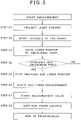
- Step 01 The surveying instrument 1 is set up at a known position.
- the tracking optical axis 49 is offset at a known value from the distance measuring optical axis 33 and the laser pointer optical axis 34. It is to be noted that in a case where the offset amount is fixed, this procedure may be omitted.
- the laser pointer projecting unit 30 is driven, and the laser pointer beam 26 is projected.
- Step 02 Next, by inputting the starting of tracking of the target 2 by the controller 3, a tracking light is projected from the tracking unit 20.
- the tracking is started.
- the surveying instrument main unit 7 is rotated and moved in a horizontal direction via the horizontal rotary unit 8 so that the tracking reflection light is received by the image pickup element 31, and the telescope unit 12 is rotated in a vertical direction via the horizontal shaft 13.
- Step 03 After the tracking is started, the operator moves the target 2 to a point near the measuring point and the laser pointer beam 26 is guided to the measuring point while visually inspecting the measuring point and the projecting point of the laser pointer beam 26.
- Step 04 and Step 05 After guiding the laser pointer beam 26 to the measuring point, it is judged whether or not the projecting point of the laser pointer beam 26 coincides with the measuring point. In a case where it is judged that the projecting point of the laser pointer beam 26 does not coincide with the measuring point, guiding of the laser pointer beam 26 is performed again. Further, in a case where it is judged that the projecting point of the laser pointer beam 26 coincides with the measuring point, the tracking and the projection of the laser pointer beam 26 are stopped via the controller 3.
- Step 06 After the tracking and the projecting of the laser pointer beam 26 has stopped, by inputting the starting of measurement via the controller 3, a command to start the measurement is transmitted to the surveying instrument 1 from the controller 3.
- the surveying instrument 1 starts the measurement of the measuring point and a non-prism distance measurement and an angle measurement are carried out.
- the distance measuring optical axis 33 coincides with the laser pointer optical axis 34, there is no need to correct a horizontal angle and a vertical angle when the measurement of the measuring point is performed.
- Step 07 After measuring the measuring point, a distance to the measuring point and an angle of the measuring point (horizontal angle and vertical angle) are stored in the storage part 37.
- Step 08 After the measurement result is stored, the surveying instrument main unit 7 is driven so that the reflection light (i.e. tracking reflection light) from the target 2 is positioned within the predetermined range with the tracking optical axis 49 as the center. Prism lock processing is performed in order to prepare a condition capable of tracking the target 2, and a condition capable of performing the next measurement is prepared.
- the reflection light i.e. tracking reflection light
- Step 08 may be omitted.
- Step 01 and Step 02 is carried out again, and after the projection of the laser pointer beam 26 and the tracking have been started, the operator moves the target 2 and guides the laser pointer beam 26, and the process of Step 05 to Step 08 is performed.
- Step 01 to Step 08 may be carried out again.
- the laser pointer optical axis 34 of the laser pointer beam 26 is offset from the tracking optical axis 49 for tracking the target 2, and the laser pointer beam 26 is projected without being reflected by the target 2. Therefore, the operator can manually guide the laser pointer beam 26 to the measuring point while visually watching the projecting point of the laser pointer beam 26.
- the laser pointer beam 26 is to be guided to the measuring point near the measuring point and there is no need to perform sighting of the measuring point from the direction of the surveying instrument 1, even in a case where the distance between the measuring point and the surveying instrument 1 is distant from each other, it is possible to guide the laser pointer beam 26 to the measuring point in a quick and an assured manner.
- the laser pointer beam 26 is guided to the measuring point by visual inspection while moving the target 2 manually and not via the controller 3, even when guiding is difficult to perform sensually while visually watching the display unit 44 such as the case where point group to be measured is tilted, or the like, a guiding is accomplished in an easy manner by visual inspection.
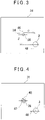
- FIG.6 description will be given on a first example of the present disclosure not falling under the scope of the present invention. It is to be noted that in FIG.6 , the same component as shown in FIG.3 is referred by the same symbol, and detailed description is omitted.
- the tracking optical axis 49 coincides with the distance measuring optical axis 33 (see FIG.1 ), and the laser pointer optical axis 34 (see FIG.1 ) is offset by an amount of the predetermined offset angle from the tracking optical axis 49 and the distance measuring optical axis 33.
- the tracking optical axis 49 is positioned at the center of the image pickup element 31 and the laser pointer optical axis 34 is offset from the tracking optical axis 49 by an amount of the offset angle as set up.
- the laser pointer optical axis 34 is offset only in the direction of Y-axis from the tracking optical axis 49 (shown by " ⁇ " in FIG. 6 ), and the laser pointer optical axis 34 is positioned out of the photodetection range of the image pickup element 31.
- an offset angle of the laser pointer optical axis 34 is set up. It is to be noted that similarly to the first embodiment, in a case where the offset angle is set in a fixed manner, the set up procedure of the offset angle may be omitted.
- a tracking light is projected from the tracking unit 20, the tracking reflection light is received by the image pickup element 31 and the tracking is started.
- the operator moves the target 2 to the measuring point and by making the surveying instrument 1 track the target 2, the laser pointer beam 26 is guided to the measuring point.
- a guiding completion signal is transmitted to the surveying instrument 1.
- the arithmetic part 36 is configured so as to rotate the telescope unit 12 by the amount of the offset angle as set up, to move the distance measuring optical axis 33 to the measuring point and to perform distance measurement and angle measurement.
- the laser pointer optical axis 34 of the laser point beam 26 in the tracking process it is not necessary for the laser pointer optical axis 34 of the laser point beam 26 in the tracking process to be within the image pickup range, and as shown in FIG.6 , if the offset angle is set up so that the reflection light of the laser pointer beam 26 is deviated from the image pickup range, the reflection light of the laser pointer beam 26 is not reflected in the image pickup element 31. As a result, it is possible to prevent an erroneous operation in which the surveying instrument 1 tracks the reflection light of the laser pointer beam 26 and it is possible to improve the stability of the tracking. Further, unlike the first embodiment, performing of mask processing and cutting of the laser pointer beam 26 by filter and the like will not be necessary.
- a mechanism capable of changing the tilting of the laser pointer optical axis 34, is added to the laser pointer projecting unit 30 (see FIG.2 ), and the mechanism is capable of setting up in an arbitrary manner, the offset angle between the laser pointer optical axis 34 and the tracking optical axis 49, even at a place where the guiding is difficult to perform near the measuring point such as a case where the measuring point is on the ceiling, or the like, it is possible to easily guide to the measuring point manually while visually watching the projecting point of the laser pointer beam 26, which contributes to the improvement of workability and to the improvement of working efficiency.
- the laser pointer optical axis 34 of the laser pointer beam 26 is designed as being offset only in Y-axis direction, but similarly to the first embodiment, the offset may be in two directions, i.e. X-axis direction and Y-axis direction.
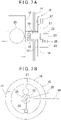
- FIG.7A and FIG.7B a description will be given on a second example of the present disclosure not falling under the scope of the present invention.
- a laser pointer 25 is provided outside the telescope unit 12, and further, it is so arranged that the offset angle of the laser pointer optical axis 34 is capable of being freely set with respect to the optical axis of the telescope unit 12.
- FIG.7A and FIG.7B the same component as shown in FIG.1 is referred by the same symbol.
- the telescope unit 12 is provided on a casing 14 via a horizontal shaft 13, and the telescope unit 12 is adapted to rotate integrally with the horizontal shaft 13.
- reference numeral 28 denotes a sighting telescope.
- a circular plate 15 On an end surface of the horizontal shaft 13, a circular plate 15 is fixed concentrically with the horizontal shaft 13. On a peripheral portion of the circular plate 15, an encoder pattern 16 such as an absolute encoder pattern or the like is formed. Further, a reading unit 17 is provided on the casing 14 and by detecting a rotation amount of the encoder pattern 16 by the reading unit 17, a rotation amount of the telescope unit 12, i.e. the vertical angle, is detected. The encoder pattern 16 and the reading unit 17 make up together a vertical angle detector 18.
- an offset shaft 19 concentric with the horizontal shaft 13 and penetrating the circular plate 15 is provided in such a manner that the offset shaft 19 is capable of being relatively rotatable in the horizontal shaft 13.
- an auxiliary shaft 22 is provided via a joint 21 and the auxiliary shaft 22 is protruded from the end surface of the horizontal shaft 13.
- the auxiliary shaft 22 is adapted to be rotatable and tiltable via the joint 21 with the horizontal shaft 13 as a center.
- a mirror 23 is provided on an end surface of the offset shaft 19 and a reflection surface of the mirror 23 is set so as to include an axial center of the offset shaft 19.
- a laser pointer supporting member 24 is protruded.
- the laser pointer 25 is provided on the laser pointer supporting member 24.
- the laser pointer optical axis 34 of the laser pointer 25 is set so as to perpendicularly cross the axial center of the offset shaft 19 and to enter a reflection surface of the mirror 23.
- the laser pointer beam 26 projected from the laser pointer 25 is arranged so as to be reflected in the direction of a measuring point by the mirror 23.
- an offset shaft motor 27 is provided, which is an offset driving unit where a motor and an encoder are integrated together.
- the offset shaft motor 27 is capable of being rotated and driven in two axial directions.
- the offset shaft motor 27 is arranged so as to relatively rotate the offset shaft 19 in the direction of Y-axis with respect to the horizontal shaft 13 and tilts the auxiliary shaft 22 in the direction of X-axis (i.e. a perpendicular direction with respect to Y-axis) around the joint 21.
- the offset shaft motor 27 is capable of detecting rotation amount of the offset shaft 19 in X-axis direction and in Y-axis direction respectively.
- the offset shaft 19 and the offset shaft motor 27 make up together an offset unit 40 (see FIG.2 ).
- the offset shaft 19 When the offset shaft 19 is rotated in Y-axis direction and the auxiliary shaft 22 is tilted in X-axis direction by the offset shaft motor 27, the mirror 23 is rotated and tilted integrally with the joint 21 in two directions, and thereby it becomes possible to change the projecting direction, i.e. offset angle, of the laser pointer beam 26 reflected by the mirror 23.
- the offset shaft 19 rotates integrally with the horizontal shaft 13 and the offset angle is fixed.
- the offset shaft 19 is not provided and the laser pointer 25 may be mounted on the horizontal shaft 13 directly, as shown in FIG.8A and FIG.8B .
- Step 11 First, the laser pointer 25 is driven and the laser pointer beam 26 is projected.
- Step 12 an offset angle of the laser pointer optical axis 34 is set up at a known value via the operation unit 45 (see FIG.2 ) of the controller 3 and an optical axis of the laser pointer beam 26 is offset.
- Step 13 After the offset of the optical axis of the laser pointer beam 26, a tracking light is emitted from the surveying instrument main unit 7 via the controller 3 and a tracking of the target 2 is started.
- Step 14 After starting the tracking, the operator moves the target 2 to a point near the measuring point and guides the laser pointer beam 26 to the measuring point while visually watching the projecting point of the laser pointer beam 26.
- Step 15 and Step 16 After the laser pointer beam 26 is guided to the measuring point, it is judged whether or not the projecting point of the laser pointer beam 26 is coincided with the measuring point. In a case where it is judged that the projecting point of the laser pointer beam 26 does not coincide with the measuring point, the guiding of the laser pointer beam 26 is performed again. Further, in a case where it is judged that the projecting point of the laser pointer beam 26 coincides with the measuring point, the tracking and the projection of the laser pointer beam 26 are stopped via the controller 3 and the completion of the guiding is inputted. It is to be noted that the projection of the laser pointer beam 26 may be stopped by inputting the completion of the guiding.
- Step 17 After the stopping of projection of the laser pointer beam 26 and the tracking, when the completion of the guiding is inputted, a signal of the completion of the guiding is transmitted to the communication unit 38 (see FIG.2 ) of the surveying instrument 1 from the communication unit 43 (see FIG.2 ).
- the arithmetic part 36 (see FIG.2 ) rotates the horizontal shaft 13 in a direction reverse to the offset by an amount of the offset angle as set up in Step 12 based on the signal of the completion of the guiding, and the distance measuring optical axis 33 is sighted to the measuring point.
- Step 18 Next, by inputting the starting of measurement via the controller 3, the measurement of the measuring point is started by the surveying instrument 1 and non-prism distance measurement and angle measurement are carried out.
- Step 19 After the measuring of the measuring point, distance to the measuring point and angle of the measuring point are stored in the storage part 37 (see FIG.2 ).
- Step 20 After storing the measurement result, the surveying instrument main unit 7 is driven so that the target 2 is positioned within a predetermined range with the tracking optical axis 49 as the center. Prism lock processing is performed in order to prepare a condition capable of tracking the target 2, and a condition capable of performing the next measurement is prepared.
- Step 20 may be omitted.
- an omnidirectional prism 5 (see FIG.1 ) is used as the target 2 in the first embodiment and the first example, it is needless to say that other reflection member such as a reflection tape, etc. may be used.
Claims (1)
- Vermessungsinstrument, umfassend einen Laserzeiger (25), der ausgelegt ist zum Projizieren eines sichtbaren Laserzeigerstrahls (26), eine Messeinheit (10, 18, 32), die ausgelegt ist zum Emittieren eines Distanzmesslichts über eine Teleskopeinheit (12), ausgelegt zum Durchführen einer Distanzmessung auf einem Messpunkt durch Empfangen eines reflektierten Lichts und ausgelegt zum Messen eines Winkels des Messpunkts, eine Bildempfangseinheit (29), ausgelegt zum Erfassen eines ein Ziel (2) enthaltenden Bilds über die Teleskopeinheit, wobei das Ziel ein Reflexionsglied (5) umfasst, das Vermessungsinstrument weiter eine Verfolgungseinheit (20) umfasst, ausgelegt zum Emittieren eines Verfolgungslichts über die Teleskopeinheit und ausgelegt zum Verfolgen des Ziels durch Empfangen eines Reflexionslichts von dem Ziel, eine Ansteuereinheit (39), ausgelegt zum Drehen der Teleskopeinheit in einer horizontalen Richtung und in einer vertikalen Richtung, und eine Steuereinheit (35), ausgelegt zum Steuern der Ansteuereinheit, so dass das Reflexionslicht der Verfolgungseinheit von dem Ziel an einer vorbestimmten Position auf einem Bildaufnahmeelement (31) der Bildaufnahmeeinheit positioniert sein wird, und ausgelegt zum Durchführen einer Verfolgung des Ziels, wobei eine optische Achse (33) des Distanzmesslichts und eine optische Achse (49) des Verfolgungslichts in einer bekannten Beziehung bestehen, eine optische Achse (34) des Laserzeigerstrahls von einer optischen Achse des Verfolgungslichts um einen vorbestimmten Offsetwinkel eingestellt ist, der Laserzeigerstrahl dadurch eingerichtet ist zum Projizieren auf eine Position wie versetzt durch den vorbestimmten Offsetwinkel bezüglich der optischen Achse des Verfolgungslichts,wobei die optische Achse (33) des Distanzmesslichts der Messeinheit (32) koaxial mit der optischen Achse (34) des Laserzeigerstrahls (26) verläuft und die optische Achse des Laserzeigerstrahls in einer Mitte auf dem Bildaufnahmeelement (31) positioniert ist, ein Wellenlängenwahlfilter auf der Verfolgungseinheit (20) vorgesehen ist und ausgelegt ist zum Beschneiden einer Wellenlänge des Laserzeigerstrahls, so dass ein Reflexionslicht des Laserzeigerstrahls (26) durch das Bildaufnahmeelement (31) nicht empfangen wird,und die Steuereinrichtung so ausgelegt ist, um zu bewirken, dass die Verfolgungseinheit das Ziel verfolgt, wenn Reflexionslicht von dem Ziel (2) empfangen wird,wobei das Vermessungsinstrument so ausgelegt ist, dass, wenn der Laserzeigerstrahl (26) projiziert wird, das Verfolgungslicht emittiert wird und die Verfolgung des Ziels gestartet wird.
Applications Claiming Priority (2)
| Application Number | Priority Date | Filing Date | Title |
|---|---|---|---|
| JP2013271153A JP6253973B2 (ja) | 2013-12-27 | 2013-12-27 | 測量装置 |
| EP14198605.9A EP2889576A1 (de) | 2013-12-27 | 2014-12-17 | Vermessungsinstrument |
Related Parent Applications (1)
| Application Number | Title | Priority Date | Filing Date |
|---|---|---|---|
| EP14198605.9A Division EP2889576A1 (de) | 2013-12-27 | 2014-12-17 | Vermessungsinstrument |
Publications (2)
| Publication Number | Publication Date |
|---|---|
| EP3677872A1 EP3677872A1 (de) | 2020-07-08 |
| EP3677872B1 true EP3677872B1 (de) | 2023-01-25 |
Family
ID=52102595
Family Applications (2)
| Application Number | Title | Priority Date | Filing Date |
|---|---|---|---|
| EP20159851.3A Active EP3677872B1 (de) | 2013-12-27 | 2014-12-17 | Vermessungsinstrument |
| EP14198605.9A Ceased EP2889576A1 (de) | 2013-12-27 | 2014-12-17 | Vermessungsinstrument |
Family Applications After (1)
| Application Number | Title | Priority Date | Filing Date |
|---|---|---|---|
| EP14198605.9A Ceased EP2889576A1 (de) | 2013-12-27 | 2014-12-17 | Vermessungsinstrument |
Country Status (4)
| Country | Link |
|---|---|
| US (1) | US9581442B2 (de) |
| EP (2) | EP3677872B1 (de) |
| JP (1) | JP6253973B2 (de) |
| CN (1) | CN104749578A (de) |
Families Citing this family (26)
| Publication number | Priority date | Publication date | Assignee | Title |
|---|---|---|---|---|
| EP2557392A1 (de) * | 2011-08-11 | 2013-02-13 | Leica Geosystems AG | Vermessungsgerät und Verfahren mit einer auf der Ausrichtung einer Fernbedieneinheit basierenden und skalierbaren Anzielfunktionalität |
| JP6118518B2 (ja) * | 2012-07-26 | 2017-04-19 | 株式会社ニコン・トリンブル | 測量装置及びプログラム |
| DE102012223929A1 (de) * | 2012-12-20 | 2014-06-26 | Hilti Aktiengesellschaft | Verfahren und Vorrichtung zum Bestimmen der zweidimensionalen Ortskoordinaten eines Zielobjektes |
| JP6141659B2 (ja) * | 2013-03-15 | 2017-06-07 | 株式会社トプコン | 測量装置 |
| EP2781879B1 (de) * | 2013-03-19 | 2015-09-30 | Leica Geosystems AG | Konstruktionslasersystem aus Rotationslaser und Laserreceiver, mit Funktionalität zur automatischen Bestimmung der Laserreceiver-Richtung |
| CN107076551B (zh) * | 2014-09-19 | 2021-02-02 | 海克斯康测量技术有限公司 | 多模式便携式坐标测量机 |
| US9354057B2 (en) * | 2014-09-26 | 2016-05-31 | Trimble Navigation Limited | Electronic rod reader and field notebook |
| US20160356889A1 (en) * | 2015-06-05 | 2016-12-08 | Magenium Solutions LLC | Laser Measuring System and Method |
| JP6246168B2 (ja) * | 2015-09-10 | 2017-12-13 | アジア建設工業株式会社 | 水中捨石均し方法 |
| CN106624764B (zh) * | 2015-10-30 | 2023-06-06 | 深圳中集天达空港设备有限公司 | 一种设备安装姿态的校正装置及方法 |
| JP6713847B2 (ja) | 2016-06-14 | 2020-06-24 | 株式会社トプコン | 測量システム |
| JP6680628B2 (ja) * | 2016-06-15 | 2020-04-15 | 株式会社トプコン | レーザスキャナ |
| JP6966184B2 (ja) * | 2016-06-15 | 2021-11-10 | 株式会社トプコン | 測量システム |
| CN105910575B (zh) * | 2016-06-22 | 2019-01-29 | 北京林业大学 | 一种新型测高方法及测高仪 |
| JP6770876B2 (ja) * | 2016-11-15 | 2020-10-21 | 株式会社トプコン | 測量機 |
| JP6864653B2 (ja) * | 2018-06-21 | 2021-04-28 | 株式会社トプコン | 鉛直測定システム及び基準点のトレース方法 |
| EP3640677B1 (de) | 2018-10-17 | 2023-08-02 | Trimble Jena GmbH | Verfolger einer vermessungsvorrichtung zur verfolgung eines ziels |
| EP3640590B1 (de) | 2018-10-17 | 2021-12-01 | Trimble Jena GmbH | Vermessungsvorrichtung zur vermessung eines objekts |
| CN109917432B (zh) * | 2019-01-31 | 2020-05-08 | 北京讯腾智慧科技股份有限公司 | 一种受限空间内的rtk测量系统和测量方法 |
| EP3696498A1 (de) | 2019-02-15 | 2020-08-19 | Trimble Jena GmbH | Vermessungsinstrument und verfahren zur kalibrierung eines vermessungsinstruments |
| CN110398748B (zh) * | 2019-07-19 | 2022-05-31 | Oppo广东移动通信有限公司 | 距离测量装置及设备、方法 |
| JP7299669B2 (ja) * | 2019-08-28 | 2023-06-28 | 株式会社トプコン | ガイド光照射部を備えた測量機 |
| CN112815929B (zh) * | 2020-12-31 | 2022-03-29 | 美国西北仪器公司 | 使用激光扫平仪追踪探测器的方法及激光追踪系统 |
| CN113447942A (zh) * | 2021-08-31 | 2021-09-28 | 深圳市众安邦智能科技有限公司 | 一种可追踪目标的无线测距装置 |
| JP7133078B1 (ja) | 2021-10-14 | 2022-09-07 | 株式会社インフォマティクス | 計測システム、計測方法及びプログラム |
| CN114942014B (zh) * | 2022-04-15 | 2023-10-31 | 中国科学院微电子研究所 | 直射式激光跟踪仪、目标跟踪恢复方法、设备及存储介质 |
Citations (1)
| Publication number | Priority date | Publication date | Assignee | Title |
|---|---|---|---|---|
| EP0716288B1 (de) * | 1994-12-09 | 2000-04-19 | Kabushiki Kaisha Topcon | Vermessungsinstrument |
Family Cites Families (25)
| Publication number | Priority date | Publication date | Assignee | Title |
|---|---|---|---|---|
| US4023908A (en) * | 1974-07-29 | 1977-05-17 | Sanders Associates, Inc. | Direction determining method and apparatus |
| US3970391A (en) * | 1974-07-29 | 1976-07-20 | Sanders Associates, Inc. | Direction determining method and apparatus |
| US4030832A (en) * | 1975-02-10 | 1977-06-21 | Spectra-Physics, Inc. | Automatic grade rod and method of operation |
| JP3621123B2 (ja) | 1993-12-28 | 2005-02-16 | 株式会社トプコン | 測量機 |
| JP4458530B2 (ja) * | 2004-09-13 | 2010-04-28 | 株式会社 ソキア・トプコン | トータルステーション |
| CN101031817B (zh) * | 2004-09-30 | 2011-02-09 | Faro科技有限公司 | 测量移动后向反射器的绝对测距仪 |
| TWI261107B (en) * | 2005-02-03 | 2006-09-01 | Asia Optical Co Inc | Laser tilt apparatus and the method thereof |
| JP4819522B2 (ja) * | 2006-02-21 | 2011-11-24 | 株式会社トプコン | 整準方法及び整準装置 |
| JP5056362B2 (ja) * | 2007-02-06 | 2012-10-24 | 株式会社デンソーウェーブ | レーザレーダ装置 |
| JP4246258B2 (ja) * | 2007-07-23 | 2009-04-02 | パナソニック株式会社 | 測距機能を有する複眼方式の撮像装置 |
| US7627448B2 (en) * | 2007-10-23 | 2009-12-01 | Los Alamost National Security, LLC | Apparatus and method for mapping an area of interest |
| JP5124319B2 (ja) | 2008-03-21 | 2013-01-23 | 株式会社トプコン | 測量機、測量システム、測定対象の検出方法、および測定対象の検出プログラム |
| JP5150329B2 (ja) * | 2008-03-26 | 2013-02-20 | 株式会社トプコン | 測量装置及び測量システム |
| JP5384512B2 (ja) * | 2008-10-21 | 2014-01-08 | 株式会社 ソキア・トプコン | 視準アシスト装置を備えた手動式測量機 |
| US7841094B2 (en) * | 2009-01-27 | 2010-11-30 | Trimble Kaiserslautern Gmbh | Optical instrument with angle indicator and method for operating the same |
| GB2501390B (en) | 2010-09-08 | 2014-08-06 | Faro Tech Inc | A laser scanner or laser tracker having a projector |
| JP5725922B2 (ja) | 2011-03-25 | 2015-05-27 | 株式会社トプコン | 測量システム及びこの測量システムに用いる測量用ポール及びこの測量システムに用いる携帯型無線送受信装置 |
| JP5796998B2 (ja) * | 2011-04-28 | 2015-10-21 | 株式会社トプコン | 測設点指示装置及び測量システム |
| EP2620745A1 (de) * | 2012-01-30 | 2013-07-31 | Hexagon Technology Center GmbH | Vermessungssystem mit einem Vermessungsgerät und einem Scanmodul |
| EP2639548A1 (de) * | 2012-03-15 | 2013-09-18 | Leica Geosystems AG | Laserempfänger mit Funktion zur Erkennung der eigenen Bewegungen |
| US8826553B2 (en) * | 2012-04-20 | 2014-09-09 | Trimble Navigation Limited | Layout equipment and layout method |
| EP2789973B1 (de) * | 2013-04-12 | 2017-11-22 | Hexagon Technology Center GmbH | Rotationslaser mit durch Aktuatoren gezielt verformbarer Linse |
| US9255798B2 (en) * | 2013-06-10 | 2016-02-09 | Keith Kahlow | Survey device |
| CN103412312A (zh) * | 2013-07-03 | 2013-11-27 | 王振兴 | 激光测距方法及装置 |
| JP6282074B2 (ja) * | 2013-09-30 | 2018-02-21 | 株式会社トプコン | レーザ測量システム |
-
2013
- 2013-12-27 JP JP2013271153A patent/JP6253973B2/ja active Active
-
2014
- 2014-12-04 US US14/560,429 patent/US9581442B2/en active Active
- 2014-12-17 EP EP20159851.3A patent/EP3677872B1/de active Active
- 2014-12-17 EP EP14198605.9A patent/EP2889576A1/de not_active Ceased
- 2014-12-26 CN CN201410823295.2A patent/CN104749578A/zh active Pending
Patent Citations (1)
| Publication number | Priority date | Publication date | Assignee | Title |
|---|---|---|---|---|
| EP0716288B1 (de) * | 1994-12-09 | 2000-04-19 | Kabushiki Kaisha Topcon | Vermessungsinstrument |
Also Published As
| Publication number | Publication date |
|---|---|
| US20150185008A1 (en) | 2015-07-02 |
| JP6253973B2 (ja) | 2017-12-27 |
| CN104749578A (zh) | 2015-07-01 |
| US9581442B2 (en) | 2017-02-28 |
| EP2889576A1 (de) | 2015-07-01 |
| EP3677872A1 (de) | 2020-07-08 |
| JP2015125099A (ja) | 2015-07-06 |
Similar Documents
| Publication | Publication Date | Title |
|---|---|---|
| EP3677872B1 (de) | Vermessungsinstrument | |
| EP3450917B1 (de) | Vermessungssystem | |
| US10469754B2 (en) | Position guiding device, position guiding method, and position guiding program | |
| US10921430B2 (en) | Surveying system | |
| US10895632B2 (en) | Surveying system | |
| EP2068116B1 (de) | Erfassungssystem | |
| EP3136050B1 (de) | Totalstation | |
| US7081606B2 (en) | Position measuring system | |
| CA2867562A1 (en) | Three-dimensional measuring method and surveying system | |
| US20150354954A1 (en) | Surveying Instrument | |
| EP2788715B1 (de) | Robotisches nivellierungsinstrument | |
| JP7313955B2 (ja) | 測量装置、測量方法および測量用プログラム | |
| US20130269195A1 (en) | Electronic Level | |
| US20210302162A1 (en) | Surveying Instrument And Surveying System | |
| US20220099443A1 (en) | Marking system and marking method | |
| JP7289252B2 (ja) | スキャナシステムおよびスキャン方法 | |
| JP2016206130A (ja) | 三次元位置計測システム | |
| US11598637B2 (en) | Surveying instrument |
Legal Events
| Date | Code | Title | Description |
|---|---|---|---|
| PUAI | Public reference made under article 153(3) epc to a published international application that has entered the european phase |
Free format text: ORIGINAL CODE: 0009012 |
|
| STAA | Information on the status of an ep patent application or granted ep patent |
Free format text: STATUS: THE APPLICATION HAS BEEN PUBLISHED |
|
| AC | Divisional application: reference to earlier application |
Ref document number: 2889576 Country of ref document: EP Kind code of ref document: P |
|
| AK | Designated contracting states |
Kind code of ref document: A1 Designated state(s): AL AT BE BG CH CY CZ DE DK EE ES FI FR GB GR HR HU IE IS IT LI LT LU LV MC MK MT NL NO PL PT RO RS SE SI SK SM TR |
|
| STAA | Information on the status of an ep patent application or granted ep patent |
Free format text: STATUS: REQUEST FOR EXAMINATION WAS MADE |
|
| 17P | Request for examination filed |
Effective date: 20200721 |
|
| RBV | Designated contracting states (corrected) |
Designated state(s): AL AT BE BG CH CY CZ DE DK EE ES FI FR GB GR HR HU IE IS IT LI LT LU LV MC MK MT NL NO PL PT RO RS SE SI SK SM TR |
|
| GRAP | Despatch of communication of intention to grant a patent |
Free format text: ORIGINAL CODE: EPIDOSNIGR1 |
|
| STAA | Information on the status of an ep patent application or granted ep patent |
Free format text: STATUS: GRANT OF PATENT IS INTENDED |
|
| INTG | Intention to grant announced |
Effective date: 20221103 |
|
| GRAS | Grant fee paid |
Free format text: ORIGINAL CODE: EPIDOSNIGR3 |
|
| GRAA | (expected) grant |
Free format text: ORIGINAL CODE: 0009210 |
|
| STAA | Information on the status of an ep patent application or granted ep patent |
Free format text: STATUS: THE PATENT HAS BEEN GRANTED |
|
| AC | Divisional application: reference to earlier application |
Ref document number: 2889576 Country of ref document: EP Kind code of ref document: P |
|
| AK | Designated contracting states |
Kind code of ref document: B1 Designated state(s): AL AT BE BG CH CY CZ DE DK EE ES FI FR GB GR HR HU IE IS IT LI LT LU LV MC MK MT NL NO PL PT RO RS SE SI SK SM TR |
|
| REG | Reference to a national code |
Ref country code: GB Ref legal event code: FG4D |
|
| REG | Reference to a national code |
Ref country code: CH Ref legal event code: EP |
|
| REG | Reference to a national code |
Ref country code: AT Ref legal event code: REF Ref document number: 1546185 Country of ref document: AT Kind code of ref document: T Effective date: 20230215 Ref country code: IE Ref legal event code: FG4D |
|
| REG | Reference to a national code |
Ref country code: DE Ref legal event code: R096 Ref document number: 602014086172 Country of ref document: DE |
|
| REG | Reference to a national code |
Ref country code: LT Ref legal event code: MG9D |
|
| REG | Reference to a national code |
Ref country code: NL Ref legal event code: MP Effective date: 20230125 |
|
| REG | Reference to a national code |
Ref country code: AT Ref legal event code: MK05 Ref document number: 1546185 Country of ref document: AT Kind code of ref document: T Effective date: 20230125 |
|
| PG25 | Lapsed in a contracting state [announced via postgrant information from national office to epo] |
Ref country code: NL Free format text: LAPSE BECAUSE OF FAILURE TO SUBMIT A TRANSLATION OF THE DESCRIPTION OR TO PAY THE FEE WITHIN THE PRESCRIBED TIME-LIMIT Effective date: 20230125 |
|
| PG25 | Lapsed in a contracting state [announced via postgrant information from national office to epo] |
Ref country code: RS Free format text: LAPSE BECAUSE OF FAILURE TO SUBMIT A TRANSLATION OF THE DESCRIPTION OR TO PAY THE FEE WITHIN THE PRESCRIBED TIME-LIMIT Effective date: 20230125 Ref country code: PT Free format text: LAPSE BECAUSE OF FAILURE TO SUBMIT A TRANSLATION OF THE DESCRIPTION OR TO PAY THE FEE WITHIN THE PRESCRIBED TIME-LIMIT Effective date: 20230525 Ref country code: NO Free format text: LAPSE BECAUSE OF FAILURE TO SUBMIT A TRANSLATION OF THE DESCRIPTION OR TO PAY THE FEE WITHIN THE PRESCRIBED TIME-LIMIT Effective date: 20230425 Ref country code: LV Free format text: LAPSE BECAUSE OF FAILURE TO SUBMIT A TRANSLATION OF THE DESCRIPTION OR TO PAY THE FEE WITHIN THE PRESCRIBED TIME-LIMIT Effective date: 20230125 Ref country code: LT Free format text: LAPSE BECAUSE OF FAILURE TO SUBMIT A TRANSLATION OF THE DESCRIPTION OR TO PAY THE FEE WITHIN THE PRESCRIBED TIME-LIMIT Effective date: 20230125 Ref country code: HR Free format text: LAPSE BECAUSE OF FAILURE TO SUBMIT A TRANSLATION OF THE DESCRIPTION OR TO PAY THE FEE WITHIN THE PRESCRIBED TIME-LIMIT Effective date: 20230125 Ref country code: ES Free format text: LAPSE BECAUSE OF FAILURE TO SUBMIT A TRANSLATION OF THE DESCRIPTION OR TO PAY THE FEE WITHIN THE PRESCRIBED TIME-LIMIT Effective date: 20230125 Ref country code: AT Free format text: LAPSE BECAUSE OF FAILURE TO SUBMIT A TRANSLATION OF THE DESCRIPTION OR TO PAY THE FEE WITHIN THE PRESCRIBED TIME-LIMIT Effective date: 20230125 |
|
| PG25 | Lapsed in a contracting state [announced via postgrant information from national office to epo] |
Ref country code: SE Free format text: LAPSE BECAUSE OF FAILURE TO SUBMIT A TRANSLATION OF THE DESCRIPTION OR TO PAY THE FEE WITHIN THE PRESCRIBED TIME-LIMIT Effective date: 20230125 Ref country code: PL Free format text: LAPSE BECAUSE OF FAILURE TO SUBMIT A TRANSLATION OF THE DESCRIPTION OR TO PAY THE FEE WITHIN THE PRESCRIBED TIME-LIMIT Effective date: 20230125 Ref country code: IS Free format text: LAPSE BECAUSE OF FAILURE TO SUBMIT A TRANSLATION OF THE DESCRIPTION OR TO PAY THE FEE WITHIN THE PRESCRIBED TIME-LIMIT Effective date: 20230525 Ref country code: GR Free format text: LAPSE BECAUSE OF FAILURE TO SUBMIT A TRANSLATION OF THE DESCRIPTION OR TO PAY THE FEE WITHIN THE PRESCRIBED TIME-LIMIT Effective date: 20230426 Ref country code: FI Free format text: LAPSE BECAUSE OF FAILURE TO SUBMIT A TRANSLATION OF THE DESCRIPTION OR TO PAY THE FEE WITHIN THE PRESCRIBED TIME-LIMIT Effective date: 20230125 |
|
| REG | Reference to a national code |
Ref country code: DE Ref legal event code: R097 Ref document number: 602014086172 Country of ref document: DE |
|
| PG25 | Lapsed in a contracting state [announced via postgrant information from national office to epo] |
Ref country code: SM Free format text: LAPSE BECAUSE OF FAILURE TO SUBMIT A TRANSLATION OF THE DESCRIPTION OR TO PAY THE FEE WITHIN THE PRESCRIBED TIME-LIMIT Effective date: 20230125 Ref country code: RO Free format text: LAPSE BECAUSE OF FAILURE TO SUBMIT A TRANSLATION OF THE DESCRIPTION OR TO PAY THE FEE WITHIN THE PRESCRIBED TIME-LIMIT Effective date: 20230125 Ref country code: EE Free format text: LAPSE BECAUSE OF FAILURE TO SUBMIT A TRANSLATION OF THE DESCRIPTION OR TO PAY THE FEE WITHIN THE PRESCRIBED TIME-LIMIT Effective date: 20230125 Ref country code: DK Free format text: LAPSE BECAUSE OF FAILURE TO SUBMIT A TRANSLATION OF THE DESCRIPTION OR TO PAY THE FEE WITHIN THE PRESCRIBED TIME-LIMIT Effective date: 20230125 Ref country code: CZ Free format text: LAPSE BECAUSE OF FAILURE TO SUBMIT A TRANSLATION OF THE DESCRIPTION OR TO PAY THE FEE WITHIN THE PRESCRIBED TIME-LIMIT Effective date: 20230125 |
|
| PG25 | Lapsed in a contracting state [announced via postgrant information from national office to epo] |
Ref country code: SK Free format text: LAPSE BECAUSE OF FAILURE TO SUBMIT A TRANSLATION OF THE DESCRIPTION OR TO PAY THE FEE WITHIN THE PRESCRIBED TIME-LIMIT Effective date: 20230125 |
|
| PLBE | No opposition filed within time limit |
Free format text: ORIGINAL CODE: 0009261 |
|
| STAA | Information on the status of an ep patent application or granted ep patent |
Free format text: STATUS: NO OPPOSITION FILED WITHIN TIME LIMIT |
|
| 26N | No opposition filed |
Effective date: 20231026 |
|
| PG25 | Lapsed in a contracting state [announced via postgrant information from national office to epo] |
Ref country code: SI Free format text: LAPSE BECAUSE OF FAILURE TO SUBMIT A TRANSLATION OF THE DESCRIPTION OR TO PAY THE FEE WITHIN THE PRESCRIBED TIME-LIMIT Effective date: 20230125 |
|
| PGFP | Annual fee paid to national office [announced via postgrant information from national office to epo] |
Ref country code: DE Payment date: 20231031 Year of fee payment: 10 |