EP3677096B1 - Beleuchtungssteuerschaltung, beleuchtungsanlage und verfahren - Google Patents
Beleuchtungssteuerschaltung, beleuchtungsanlage und verfahren Download PDFInfo
- Publication number
- EP3677096B1 EP3677096B1 EP18849793.7A EP18849793A EP3677096B1 EP 3677096 B1 EP3677096 B1 EP 3677096B1 EP 18849793 A EP18849793 A EP 18849793A EP 3677096 B1 EP3677096 B1 EP 3677096B1
- Authority
- EP
- European Patent Office
- Prior art keywords
- control circuit
- circuit
- current
- supply
- led lamp
- Prior art date
- Legal status (The legal status is an assumption and is not a legal conclusion. Google has not performed a legal analysis and makes no representation as to the accuracy of the status listed.)
- Active
Links
Images


Classifications
-
- F—MECHANICAL ENGINEERING; LIGHTING; HEATING; WEAPONS; BLASTING
- F21—LIGHTING
- F21V—FUNCTIONAL FEATURES OR DETAILS OF LIGHTING DEVICES OR SYSTEMS THEREOF; STRUCTURAL COMBINATIONS OF LIGHTING DEVICES WITH OTHER ARTICLES, NOT OTHERWISE PROVIDED FOR
- F21V23/00—Arrangement of electric circuit elements in or on lighting devices
- F21V23/003—Arrangement of electric circuit elements in or on lighting devices the elements being electronics drivers or controllers for operating the light source, e.g. for a LED array
-
- F—MECHANICAL ENGINEERING; LIGHTING; HEATING; WEAPONS; BLASTING
- F21—LIGHTING
- F21V—FUNCTIONAL FEATURES OR DETAILS OF LIGHTING DEVICES OR SYSTEMS THEREOF; STRUCTURAL COMBINATIONS OF LIGHTING DEVICES WITH OTHER ARTICLES, NOT OTHERWISE PROVIDED FOR
- F21V23/00—Arrangement of electric circuit elements in or on lighting devices
- F21V23/02—Arrangement of electric circuit elements in or on lighting devices the elements being transformers, impedances or power supply units, e.g. a transformer with a rectifier
-
- H—ELECTRICITY
- H02—GENERATION; CONVERSION OR DISTRIBUTION OF ELECTRIC POWER
- H02M—APPARATUS FOR CONVERSION BETWEEN AC AND AC, BETWEEN AC AND DC, OR BETWEEN DC AND DC, AND FOR USE WITH MAINS OR SIMILAR POWER SUPPLY SYSTEMS; CONVERSION OF DC OR AC INPUT POWER INTO SURGE OUTPUT POWER; CONTROL OR REGULATION THEREOF
- H02M1/00—Details of apparatus for conversion
- H02M1/12—Arrangements for reducing harmonics from AC input or output
-
- H—ELECTRICITY
- H02—GENERATION; CONVERSION OR DISTRIBUTION OF ELECTRIC POWER
- H02M—APPARATUS FOR CONVERSION BETWEEN AC AND AC, BETWEEN AC AND DC, OR BETWEEN DC AND DC, AND FOR USE WITH MAINS OR SIMILAR POWER SUPPLY SYSTEMS; CONVERSION OF DC OR AC INPUT POWER INTO SURGE OUTPUT POWER; CONTROL OR REGULATION THEREOF
- H02M1/00—Details of apparatus for conversion
- H02M1/14—Arrangements for reducing ripples from DC input or output
-
- H—ELECTRICITY
- H02—GENERATION; CONVERSION OR DISTRIBUTION OF ELECTRIC POWER
- H02M—APPARATUS FOR CONVERSION BETWEEN AC AND AC, BETWEEN AC AND DC, OR BETWEEN DC AND DC, AND FOR USE WITH MAINS OR SIMILAR POWER SUPPLY SYSTEMS; CONVERSION OF DC OR AC INPUT POWER INTO SURGE OUTPUT POWER; CONTROL OR REGULATION THEREOF
- H02M1/00—Details of apparatus for conversion
- H02M1/42—Circuits or arrangements for compensating for or adjusting power factor in converters or inverters
- H02M1/4208—Arrangements for improving power factor of AC input
- H02M1/4266—Arrangements for improving power factor of AC input using passive elements
-
- H—ELECTRICITY
- H02—GENERATION; CONVERSION OR DISTRIBUTION OF ELECTRIC POWER
- H02M—APPARATUS FOR CONVERSION BETWEEN AC AND AC, BETWEEN AC AND DC, OR BETWEEN DC AND DC, AND FOR USE WITH MAINS OR SIMILAR POWER SUPPLY SYSTEMS; CONVERSION OF DC OR AC INPUT POWER INTO SURGE OUTPUT POWER; CONTROL OR REGULATION THEREOF
- H02M5/00—Conversion of AC power input into AC power output, e.g. for change of voltage, for change of frequency, for change of number of phases
- H02M5/02—Conversion of AC power input into AC power output, e.g. for change of voltage, for change of frequency, for change of number of phases without intermediate conversion into DC
- H02M5/04—Conversion of AC power input into AC power output, e.g. for change of voltage, for change of frequency, for change of number of phases without intermediate conversion into DC by static converters
- H02M5/10—Conversion of AC power input into AC power output, e.g. for change of voltage, for change of frequency, for change of number of phases without intermediate conversion into DC by static converters using transformers
- H02M5/18—Conversion of AC power input into AC power output, e.g. for change of voltage, for change of frequency, for change of number of phases without intermediate conversion into DC by static converters using transformers for conversion of waveform
-
- H—ELECTRICITY
- H02—GENERATION; CONVERSION OR DISTRIBUTION OF ELECTRIC POWER
- H02M—APPARATUS FOR CONVERSION BETWEEN AC AND AC, BETWEEN AC AND DC, OR BETWEEN DC AND DC, AND FOR USE WITH MAINS OR SIMILAR POWER SUPPLY SYSTEMS; CONVERSION OF DC OR AC INPUT POWER INTO SURGE OUTPUT POWER; CONTROL OR REGULATION THEREOF
- H02M7/00—Conversion of AC power input into DC power output; Conversion of DC power input into AC power output
- H02M7/02—Conversion of AC power input into DC power output without possibility of reversal
- H02M7/04—Conversion of AC power input into DC power output without possibility of reversal by static converters
- H02M7/06—Conversion of AC power input into DC power output without possibility of reversal by static converters using discharge tubes without control electrode or semiconductor devices without control electrode
-
- H—ELECTRICITY
- H05—ELECTRIC TECHNIQUES NOT OTHERWISE PROVIDED FOR
- H05B—ELECTRIC HEATING; ELECTRIC LIGHT SOURCES NOT OTHERWISE PROVIDED FOR; CIRCUIT ARRANGEMENTS FOR ELECTRIC LIGHT SOURCES, IN GENERAL
- H05B39/00—Circuit arrangements or apparatus for operating incandescent light sources
- H05B39/04—Controlling
-
- H—ELECTRICITY
- H05—ELECTRIC TECHNIQUES NOT OTHERWISE PROVIDED FOR
- H05B—ELECTRIC HEATING; ELECTRIC LIGHT SOURCES NOT OTHERWISE PROVIDED FOR; CIRCUIT ARRANGEMENTS FOR ELECTRIC LIGHT SOURCES, IN GENERAL
- H05B45/00—Circuit arrangements for operating light-emitting diodes [LED]
- H05B45/30—Driver circuits
- H05B45/345—Current stabilisation; Maintaining constant current
-
- H—ELECTRICITY
- H05—ELECTRIC TECHNIQUES NOT OTHERWISE PROVIDED FOR
- H05B—ELECTRIC HEATING; ELECTRIC LIGHT SOURCES NOT OTHERWISE PROVIDED FOR; CIRCUIT ARRANGEMENTS FOR ELECTRIC LIGHT SOURCES, IN GENERAL
- H05B45/00—Circuit arrangements for operating light-emitting diodes [LED]
- H05B45/30—Driver circuits
- H05B45/355—Power factor correction [PFC]; Reactive power compensation
-
- H—ELECTRICITY
- H05—ELECTRIC TECHNIQUES NOT OTHERWISE PROVIDED FOR
- H05B—ELECTRIC HEATING; ELECTRIC LIGHT SOURCES NOT OTHERWISE PROVIDED FOR; CIRCUIT ARRANGEMENTS FOR ELECTRIC LIGHT SOURCES, IN GENERAL
- H05B45/00—Circuit arrangements for operating light-emitting diodes [LED]
- H05B45/30—Driver circuits
- H05B45/357—Driver circuits specially adapted for retrofit LED light sources
- H05B45/3578—Emulating the electrical or functional characteristics of discharge lamps
-
- H—ELECTRICITY
- H05—ELECTRIC TECHNIQUES NOT OTHERWISE PROVIDED FOR
- H05B—ELECTRIC HEATING; ELECTRIC LIGHT SOURCES NOT OTHERWISE PROVIDED FOR; CIRCUIT ARRANGEMENTS FOR ELECTRIC LIGHT SOURCES, IN GENERAL
- H05B45/00—Circuit arrangements for operating light-emitting diodes [LED]
- H05B45/30—Driver circuits
- H05B45/37—Converter circuits
-
- H—ELECTRICITY
- H01—ELECTRIC ELEMENTS
- H01F—MAGNETS; INDUCTANCES; TRANSFORMERS; SELECTION OF MATERIALS FOR THEIR MAGNETIC PROPERTIES
- H01F38/00—Adaptations of transformers or inductances for specific applications or functions
- H01F38/02—Adaptations of transformers or inductances for specific applications or functions for non-linear operation
- H01F38/023—Adaptations of transformers or inductances for specific applications or functions for non-linear operation of inductances
-
- H—ELECTRICITY
- H02—GENERATION; CONVERSION OR DISTRIBUTION OF ELECTRIC POWER
- H02M—APPARATUS FOR CONVERSION BETWEEN AC AND AC, BETWEEN AC AND DC, OR BETWEEN DC AND DC, AND FOR USE WITH MAINS OR SIMILAR POWER SUPPLY SYSTEMS; CONVERSION OF DC OR AC INPUT POWER INTO SURGE OUTPUT POWER; CONTROL OR REGULATION THEREOF
- H02M7/00—Conversion of AC power input into DC power output; Conversion of DC power input into AC power output
- H02M7/02—Conversion of AC power input into DC power output without possibility of reversal
- H02M7/04—Conversion of AC power input into DC power output without possibility of reversal by static converters
- H02M7/05—Capacitor coupled rectifiers
-
- Y—GENERAL TAGGING OF NEW TECHNOLOGICAL DEVELOPMENTS; GENERAL TAGGING OF CROSS-SECTIONAL TECHNOLOGIES SPANNING OVER SEVERAL SECTIONS OF THE IPC; TECHNICAL SUBJECTS COVERED BY FORMER USPC CROSS-REFERENCE ART COLLECTIONS [XRACs] AND DIGESTS
- Y02—TECHNOLOGIES OR APPLICATIONS FOR MITIGATION OR ADAPTATION AGAINST CLIMATE CHANGE
- Y02B—CLIMATE CHANGE MITIGATION TECHNOLOGIES RELATED TO BUILDINGS, e.g. HOUSING, HOUSE APPLIANCES OR RELATED END-USER APPLICATIONS
- Y02B70/00—Technologies for an efficient end-user side electric power management and consumption
- Y02B70/10—Technologies improving the efficiency by using switched-mode power supplies [SMPS], i.e. efficient power electronics conversion e.g. power factor correction or reduction of losses in power supplies or efficient standby modes
Definitions
- the present invention relates to lighting and, in particular, to outdoor lighting such as street lighting or stadium lighting.
- the present invention also relates to indoor lighting (such as highbays). Hitherto such lighting has been supplied by means of High Intensity Discharge (HID) lamps.
- HID High Intensity Discharge
- HID lamps are essentially AC devices and have a negative resistance characteristic. As a consequence, power is supplied by an AC mains supply and a ballast or choke is connected in series with the lamp so as to prevent damage to the lamp from excessive currents.
- a typical HID lamp such as a 1000W Metal Halide has an ignition voltage of 750 V peak, an operating voltage of 260V and an operating current of 4A giving a lamp power of approximately 1000W and a light output of 100,000 Lumens.
- LEDs light emitting diodes
- LEDs are DC (or unidirectional current) devices.
- a LED has a positive resistance characteristic (in which the resistance varies with the current flowing through the LED).
- DC devices where LEDs are supplied from the AC mains, there is normally a rectifier of some description supplied by the mains and the LEDs (together with their drivers or control circuits) are powered by the output of the rectifier.
- the DC control circuits for LED lamps are completely different from the AC control circuits for HID lamps.
- a high powered LED has a nominal voltage of 6V and draws a nominal current of 2.1A. However, the LED can have a current of up to 4.8A.
- a LED lamp fixture may typically include 24 such LEDs connected in series. Such a LED lamp fixture has an operating voltage of 150V and a nominal operating current of 2.1A giving a lamp power of approximately 315W and a light output of 30,000 Lumens. In some cases matched LEDs are connected in parallel, in which case the total current is shared.
- Another example of a high powered LED has 36 LEDs in one string, has a nominal voltage of 225V, a nominal current of 2.1A, a nominal wattage of 475W and a light output of 45,000 Lumens.
- a control circuit in the form of an electronic driver of some kind is required to maintain the LED current within its rated limits.
- This control circuit is connected between the rectifier and the LEDs and in its simplest form comprises a single resistor.
- the output of the rectifier may have an unacceptable ripple and therefore a filter including one or more capacitors can be connected between the rectifier and the LED.
- a control circuit connected between the rectifier and the LEDs.
- PWM pulse width modulation
- a control circuit in the form of a PWM modulator is connected between the rectifier and the LEDs.
- the drivers or control circuits normally include one or more electrolytic capacitors having high levels of capacitance. This has the consequence of very high initial transient currents at starting since the capacitor(s) require large amounts of charge in order to reach their operating voltage.
- Prior art novelty searches carried out after the conception of the present invention have disclosed US Patent No 9, 497, 811 (Schijffelen ) which is illustrative of this prior art. All control is carried out between the rectifier and the string of LEDs.
- D1 US 2005/0030192 Weaver discloses a power supply system for LED airfield lighting where the LEDs are supplied with a pulse width modulated DC current which is controlled by a DC control circuit (Switching Current Regulators 430A and 430B) to vary the intensity of the LEDs.
- An AC circuit including a ferro-resonant transformer 415 is used to supply an AC voltage to a full wave rectifier 420.
- the ferro-resonant transformer acts a power supply for the Switching Current Regulators.
- the ferro-resonant capacitor 419 does not carry the current flowing through the rectifying circuit and the LED light sources 465A and 465B. The ferro-resonant activity occurs irrespective of whether current flows through the rectifier 420.
- the prior art circuit monitors the magnitude of current in a current loop 405 and a CPU processor 450 interprets the loop current and uses an algorithm to change the duty cycle of the Switching Current Regulators 430Aand 430B to make the intensity of the LEDs equivalent to the intensity of an incandescent lamp connected to the same current loop.
- the ferro-resonant transformer arrangement 415-419 is a constant voltage transformer with a conventional "tank" circuit (418-419) and supplies a constant AC voltage to the rectifier 420.
- the rectifier 420 and filtering capacitor 425 supply a constant DC voltage to the Switching Current Regulators 430A and 430B.
- the Genesis of the present invention is a desire to avoid such problems by adopting an alternative control arrangement for LED lamps.
- a control circuit for supplying a substantially constant DC current to an LED lamp unit which constitutes a load
- said control circuit comprising AC inputs for connection to an AC supply which is subject to variations including supply voltage fluctuations and transients, a pair of lamp outputs for connection to said LED lamp unit, a full wave rectifying circuit supplying a DC voltage and said substantially constant DC current to said pair of lamp outputs, and an AC control circuit, wherein said AC control circuit is connected between said AC inputs (A, N) and said rectifying circuit to reduce variations in the magnitude of an AC current supplied to said rectifying circuit from said AC control circuit to thereby reduce corresponding variations in said substantially constant DC current, said AC control circuit including a capacitor in series with an inductive winding of a magnetic component having a magnetically permeable core that at least part of which in operation is at least partially saturated by ferro-resonance, wherein said capacitor, said rectifying circuit and said LED lamp unit are electrically connectable in series to conduct a load current therethrough which
- a lighting installation comprising the above control circuit and an LED lamp fixture supplied with said substantially constant DC current via said LED lamp unit.
- a method of converting a High Intensity Discharge (HID) lamp installation supplied by an AC mains supply subject to variations including supply voltage variations and transients, and including an HID lamp fitting, a ballast and associated control gear, to an LED lamp installation including a LED lamp fitting supplied with a substantially constant DC current said method comprising the steps of:
- a particular advantage of the above method is that it enables the use of existing cabling and control gear housings that were previously used for the HID installation resulting in a simple and cost effective conversion process.
- control circuit Various forms of control circuit are disclosed as are variants of the above where the AC mains supply is a three-phase supply.
- circuits illustrated in Figs. 2 , 4 , 7 , 8 , 12 , 14 , 15 , 19-22 , and 25 do not form part of the invention but represent background art that is useful for understanding the invention.
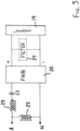
- a prior art LED lamp circuit takes the form of a transformer 11 supplied by an AC mains supply, and a full wave bridge rectifier 20 which supplies the necessary DC voltage.
- the rectifier 20 includes four regular diodes 21.
- the LED lamp 19 takes the form of a string of light emitting diodes 18.
- a control circuit in the form of resistors R1 and R2, a transistor Q1 and a controlled voltage, is provided.
- the controlled voltage where no dimming is required can take the form of a reverse biased Zener diode.
- the controlled voltage is equal to the base-emitter voltage of the transistor Q1 and the voltage across the resistor R1. Since the base emitter voltage does not vary in any significant fashion with the collector-emitter current flowing through the transistor, this means that the voltage across the resistor R1 is substantially constant. This in turn renders the current through the lamp 19 substantially constant.
- the controlled voltage itself is adjustable by a further dimmer setting circuit which enables the controlled voltage to be adjusted.
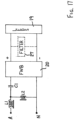
- the lamp 19 and its associated circuitry which are positioned at the top of a pole or tower, are connected to the remainder of the circuit by four wires.
- the lamp 19 is as before consisting of a sequence of series connected light emitting diodes 18.
- the lamp 19 is directly connected to a full wave bridge (FWB) rectifier 20 composed of four regular diodes 21 connected in the traditional manner for a full wave rectification.
- the rectifier 20 is supplied by an AC mains supply having an active terminal A and a neutral terminal N.
- An iron cored inductor 23 is interposed between the mains supply and the rectifier 20, preferably in the active lead as illustrated.
- the inductor 23 operates as a control circuit.
- the current supplied by the bridge rectifier 20 to the LED lamp 19 is maintained within the upper and lower limits of LED current conduction by the impedance of the inductor 23.
- the inductor 23 provides a phase shift in the mains current so that the mains current is continuous and essentially sinusoidal in shape.
- Two capacitors Ci and C27 are drawn in Fig. 2 in broken lines in order to indicate that they are optional and can be provided if desired.
- the function of capacitor C27 is to smooth out the ripple voltage provided by the Full Wave Bridge rectifier 20.
- the function of the capacitor Ci is to improve the power factor of the mains current.
- the lamp 19 can be located at the top of a tower or pole (not illustrated) and the operating circuitry in the form of the inductor 23 and rectifier 20 can be located at the base of the tower or pole. This enables an easy retrofit in order to replace existing HID lighting installations.
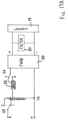
- a capacitor C1 is added in series with the inductor 23 to convert the lagging low power factor circuit of Fig. 2 (without capacitor Ci) into a leading low power factor circuit.
- the inclusion of the capacitor C1 also reduces the variation in the current supplied to the LEDs 19 due to mains voltage variations. Further reductions in current variation due to mains voltage variations can be achieved by introducing a degree of non-linearity into the inductor 23.
- an optional shunt inductor 25 (illustrated by broken lines in Fig. 3 ) can be connected across the mains terminals to improve the power factor.
- a further optional addition is the connection of a filter 27 across the output of the rectifier 20. The provision of the filter 27 attenuates the ripple in the current through the LEDs 19.
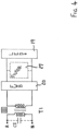
- an isolated leakage reactance transformer T1 incorporating magnetic shunts, may be connected across the mains and to substitute for the inductor 23.
- the bridge rectifier 20 and LED lamp 19 are as before.
- the optional filter 27 is also as before.
- An optional capacitor C2 can be connected across the mains terminals to improve the power factor.
- the high leakage reactance of the transformer T1 provides essentially the same phase shift in the output current as provided by the inductor 23 of Fig. 2 . As a result, there is a continuous and essentially sinusoidal current flow in both the primary and secondary windings of the isolated leakage reactance transformer T1.
- FIG. 5 An embodiment based on Fig. 4 is illustrated in Fig. 5 .
- An isolated leakage reactance transformer T2 of Fig. 5 has a capacitor C1 connected in series with its secondary winding.
- the magnetic circuit associated with the secondary winding permits partial saturation. Preferably, this is achieved by modifying the magnetic circuit.
- This non-linear nature of the secondary winding inductance in conjunction with the capacitor C1 results in a relatively constant current through the LEDs 19 irrespective of variations in the mains supply voltage.
- An alternative technique to achieve dimming is to substitute parallel capacitors for the capacitor C1. Full light output is achieved when both capacitors are in circuit but a dimmed light output is achieved when one of the two parallel capacitors is switched out of the circuit. More than one dimming level of light output can be achieved by using various combinations of series and/or parallel switched capacitors.
- Fig. 6 the circuits of Figs. 2 and 3 are combined to produce a high power factor circuit which can operate two lamps 19 in a lead-lag configuration. This is very beneficial for the mains supply network.
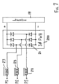
- Fig. 7 illustrates a simple three-phase modification of the circuit of Fig. 2 .
- a conventional three-phase full wave bridge rectifier 200 utilising six regular diodes 21 replaces the rectifier 20 of Fig. 2 .
- An inductor 23 is provided for each of the 3 phases P1-P3.
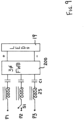
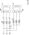
- Fig. 8 illustrates a modification of the circuit diagram of Fig. 7 in that an input shunt capacitor C2 is added for each phase. This improves the power factor of the circuit of Fig. 7 .
- the shunt capacitors C2 can be connected in Wye configuration to an optional Neutral terminal N as shown which results in a 4 wire supply.
- the shunt capacitors can be connected in Wye configuration to a floating star point.
- a Delta connection between the phases can be used for these power factor correcting capacitors C2, thereby again resulting in a 3 wire supply.
- Fig. 9 illustrates a further embodiment in which the three-phase circuit of Fig. 7 is modified by the provision of a switch S1 which enables a single phase to be turned off. This has the consequence of dropping the current supplied via the three-phase rectifier 200 to the LED lamp 19. The reduced current through the lamp 19 is, however, still within the specified current range of the lamp 19 but results in the lamp being dimmed. Such dimming is particularly useful in introducing lighting at sporting fixtures during the onset of evening. In addition to a saving in power, the eyes of the spectators and players are allowed to adjust to the artificial lighting environment. Alternatively, such dimming is an acceptable lower lighting level for training activities, as opposed to match competition. The identical dimming function is also available by switching power off to one of the phases of the circuits of Figs. 7 and 8 . In the particular embodiment of Fig. 9 , a series capacitor C1 is provided for each phase.
- Fig. 10 is a combination of the circuits of Figs. 7 and 9 which permits two LED lamps 19 to be operated in a high power factor lead-lag arrangement.
- the switch S1 enables one of the phases to be dropped to dim both lamps 19.
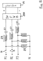
- Fig. 11 represents a three-phase version of the circuit of Fig. 3 utilising shunt inductors 25, one for each phase.
- the switch S1 can be open to provide a first level of dimming of the LEDs 19.
- an optional second switch S2 (illustrated in broken lines in Fig. 11 ) can be provided in another phase. If both switches S1 and S2 are opened, a second lower dimming level can be achieved (provided the available voltage is adequate to provide the LEDs forward voltage drop and drive sufficient current through the LEDs).
- Fig. 12 represents a three-phase version of the circuit of Fig. 4 utilising three isolated leakage reactance transformers T1, again one for each phase.
- the switch S1 enables a dimming function to be achieved.
- the three primary windings are connected in star or Wye configuration and preferably the star point is floating so as to form a 3 wire supply.
- the star point can be connected to a mains neutral terminal N so as to form a 4 wire supply.
- power factor correction capacitors C2 can be connected to the power supply terminals in either Delta or star configurations.
- Fig. 13 represents a three-phase version of the circuit of Fig. 5 utilising three isolated constant current transformers T2, again one for each phase.
- a series capacitor C1 is provided for each phase.
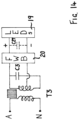
- a ferro-regulating transformer T3 has a capacitor C3 connected across its secondary winding to form a tank circuit.
- the secondary winding is tapped to provide the appropriate input voltage to the full wave bridge rectifier 20.
- the lamp 19 is as before.
- an optional filtering capacitor C27 can be connected across the output of the rectifier 20.
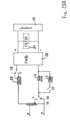
- Fig. 15 illustrates a three-phase version of the circuit of Fig. 14 utilising three ferro-regulating transformers T3.
- the three primary windings are connected in star or Wye configuration and preferably the star point is floating so as to form a 3 wire supply.
- the star point can be connected to a mains neutral terminal N so as to form a 4 wire supply.
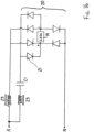
- Fig. 16 illustrates a further single phase embodiment which is a similar to Fig. 6 .
- Six diodes 21 constitute a double full wave bridge rectifier 20 which is fed via an inductor 23 on the one hand and a series connected inductor 23 and capacitor C1 on the other hand.
- both leading and lagging currents are supplied to the LEDs 19 simultaneously.
- the resultant LED current has very little ripple (approximately 5%) without any filter capacitor.
- the circuit has a very high power factor (almost unity) and low total harmonic distortion of the mains current.
- inductor L1 is a relatively linear inductor whereas inductor L2 has at least partial saturation of its core, so that the voltage across inductor L2 remains relatively constant.
- inductor L2 has at least partial saturation of its core, so that the voltage across inductor L2 remains relatively constant.
- Fig. 18 illustrates a three-phase version of Fig. 17 .
- the common connection point of inductors L2 can be either a floating star point with a 3 wire mains supply or can be connected to a neutral terminal N of a 4 wire mains supply.
- Figs. 19 and 20 each show an arrangement with an autotransformer T5 supplying the rectifier 20 from a tapped winding.
- An inductor 23 is connected in series with the autotransformer T5.
- the tapping can be selected to enable a match between the supply voltage and the reflected load voltage X-Y (being the voltage across the LEDs 19 reflected into the mains supply circuit).
- the reflected LED voltage is increased.
- the reflected LED voltage is decreased.
- power factor correction can be added by connecting a capacitor across the supply terminals.
- Figs. 19A and 20A illustrate variations able to be made to the autotransformer T5 in order to dim the LEDs 19.
- a switch S5 is connected between some of the primary winding turns of the autotransformer T5. With the switch S5 in position 2, a lower voltage is applied to the inductor 23 and thus the LEDs 19 are dimmed. With the switch S5 in position 1, the mains voltage is applied across a small number of turns of the primary winding and thus the voltage applied to the inductor 23 and rectifier 20 is increased and thus the LEDs 19 are not dimmed.
- Fig. 20A illustrates a similar arrangement but with the switch S5 connected to the secondary side of the autotransformer T5.
- the switch S5 With the switch S5 in position 1, a maximum voltage is applied to the inductor 23 and rectifier 20 and so the LEDs 19 are not dimmed. However, when the switch S5 is in position 2, a smaller voltage is applied to the inductor 23 and rectifier 20 and so the LEDs are dimmed.
- Figs. 19A and 20A also illustrate switched dimming techniques applicable to impedances located in the mains supply to the rectifiers 20, 200.
- inductor 23 has a tapping in the winding. With switch S8 in position 1, there is a lower impedance and the LEDs 19 are not dimmed. With switch S8 in position 2, the inductor 23 has a higher impedance and the LEDs 19 are dimmed.
- FIG. 20A A similar arrangement is illustrated in Fig. 20A .
- an inductor L8 is connected in series with the rectifier 20.
- a switch S7 connected in series with a further inductor L9 can be operated to connect the inductor L9 in parallel with the inductor L8, thereby increasing the current to the rectifier 20.
- the switch S7 open the LEDs 19 are dimmed and with the switch S7 closed, the LEDs 19 are un-dimmed.
- the switch S8 can be provided as in Fig. 19A to change the effective number of turns of the inductor 23. With the switch S8 in position 1, the impedance of the inductor 23 is reduced, the current to the rectifier 20 is at a maximum and the LEDs 19 are un-dimmed. However, with the switch S8 in position 2, the impedance of the inductor 23 is at a maximum, and so the current to the rectifier 20 is reduced and the LEDs are dimmed. It will be apparent to those skilled in the art that in some circuit arrangements switching of capacitors can be used as an alternative form of impedance change. Other forms of switchable series and/or parallel interconnections to alter the level of current will also be apparent to those skilled in the art.
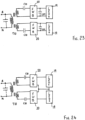
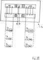
- Figs. 21-24 each illustrate a single phase circuit with an isolated high leakage transformer T10 having dual output windings. These are used to supply a pair of LED lamps 19 at an appropriate and acceptable voltage, especially in cases where a 2 wire LED voltage circuit would necessitate the use of unacceptably high voltages. Dimming can be achieved by the inclusion of additional series or parallel capacitors in the dual output windings which are switched in or out of circuit. Power factor correction can be achieved with an optional capacitor connected between the active and neutral terminals.
- the two full wave bridge rectifiers 20 are completely isolated from each other thus creating a 4 wire feed to the LED lamp modules 19.
- the two full wave bridge rectifiers 20 can have a common connection, thereby creating a 3 wire feed to the LED lamp modules 19.
- the dual output windings of the isolated high leakage transformer T10 each have a capacitor C10 connected in series.
- This arrangement provides essentially the same benefits as those associated with Fig. 5 in that the current through the LED lamp modules 19 will be relatively constant irrespective of changes in the supply voltage.
- the circuits of Figs. 21 and 22 there is the additional benefit of a reduced voltage applied to the individual LED lamp modules 19.
- Fig. 25 illustrates a single phase circuit similar to Fig. 2 save that the rectifier 20 is replaced by a transformer T4 and voltage doubler unit formed by a pair of regular diodes 21 and a pair of capacitors C4.
- An advantage of the circuit of Fig. 25 is that the voltage across the LED lamp 19 is much increased and thus can accommodate an increased number of series connected LED diodes 18.
- the lamp 19 of Fig. 25 can have an increased wattage relative to the lamps 19 of the other circuits.
- a filter 27 can be located between the rectifier 20, 200 and the LED module(s) 19. This filter can take the form of either a shunt capacitor C27, or a series inductor, or a combination of series inductor(s) and a shunt capacitor.
- the magnetic component of the control circuit can take the form of various transformers including leakage reactance transformers, ferro-resonant transformers and constant current transformers. These can be realised by either an autotransformer or by a conventional isolation transformer.
- the control circuit can also take the form of a constant current transformer as illustrated in Figs. 26 and 27 .
- the constant current transformer Tr is drawn with its primary magnetic circuit illustrated with the laminations parallel to the plane of the paper and its leakage magnetic circuit drawn with the laminations perpendicular to the plane of the paper.
- a primary winding WP is supplied with AC mains power and a secondary winding WS provides an output voltage to the load circuit(s).
- the shunts of the leakage magnetic circuit provides substantial leakage inductance, thereby magnetically de-coupling the output of the secondary winding from variations in the mains voltage.
- the magnetic circuit associated with the secondary winding WS is arranged so that at least a substantial portion thereof goes into magnetic saturation during normal operation. Preferably, this is achieved by modifying the magnetic circuit.
- the load consists of 4 regular diodes forming a full wave bridge rectifier with the LEDs module 19 forming the load.
- an optional filtering capacitor C27 can be connected in parallel with the LEDs 19.
- the secondary circuit has a very high immunity to transient voltages in the mains supply, and this immunity is applicable to both transverse mode transient voltages and common mode transient voltages.
- a small bucking winding (not illustrated but conventional) can be wound over the primary winding WP and connected in series with the secondary winding WS but in an inductively opposing sense.
- a constant current transformer Tr having a single primary winding WP and two totally independent secondary windings WS 1 and WS2.
- the single primary winding WP is located in between a pair of magnetic shunts and results in substantial saturation of the magnetic circuit of each of the secondary windings WS1 and WS2.
- Each of the secondary windings is capable of supplying a number of parallel load circuits in the manner of Fig. 26 .
- the AC mains supply can be either single phase or poly phase (normally three-phases).
- the primary windings of the transformer can be connected either in Wye configuration or in Delta configuration.
- a power factor correction circuit can be used to improve the power factor of the overall circuit.
- a typical power factor correction circuit is a shunt capacitor connected between the phases of the supply or between each phase and a star point or neutral connection.
- Power factor correction can also be implemented by duplicating the overall circuit and operating two sets of LED modules 19 in a lead-lag configuration.
- Dimming is possible by switching off one of the duplicate circuits in a lead-lag configuration, or switching off one or more of the phases of a poly phase circuit. Dimming is also possible by switching impedance(s) into and out of the supply circuit to the rectifier 20, 200. Similarly, dimming is also possible by switching turns into and out of transformer arrangements applying the rectifier 20, 200.
- a 3 wire supply or 4 wire supply is possible.
- the 3 wire supply can be delta connected, or have a floating star point.
- the 4 wire supply can have the star point connected to a neutral terminal.
Landscapes
- Engineering & Computer Science (AREA)
- Power Engineering (AREA)
- General Engineering & Computer Science (AREA)
- Microelectronics & Electronic Packaging (AREA)
- Circuit Arrangement For Electric Light Sources In General (AREA)
- Discharge-Lamp Control Circuits And Pulse- Feed Circuits (AREA)
- Dc-Dc Converters (AREA)
- Circuit Arrangements For Discharge Lamps (AREA)
Claims (15)
- Steuerschaltung zum Zuführen einer im Wesentlichen konstanten Gleichstromstärke an eine LED-Lampeneinheit (19), die eine Last darstellt, wobei die Steuerschaltung Folgendes umfasst: Wechselstromeingänge (A, N) zum Verbinden mit einer Wechselstromversorgung, die Schwankungen, einschließlich Versorgungsspannungsschwankungen und Transienten, unterliegt, ein Paar von Lampenausgängen (+, -) zum Verbinden mit der LED-Lampeneinheit, eine Vollwellen-Gleichrichterschaltung (20, 200), die so ausgelegt ist, dass sie dem Paar von Lampenausgängen eine Gleichspannung und die im Wesentlichen konstante Gleichstromstärke zuführt, und eine Wechselstromsteuerschaltung; dadurch gekennzeichnet, dass die Wechselstromsteuerschaltung zwischen den Wechselstromeingängen (A, N) und der Gleichrichterschaltung (20, 200) geschaltet ist, um Schwankungen in der Größe einer der Gleichrichterschaltung von der Wechselstromsteuerschaltung zugeführten Wechselstromstärke zu verringern, um dadurch entsprechende Schwankungen in der im Wesentlichen konstanten Gleichstromstärke zu verringern, wobei die Wechselstromsteuerschaltung einen Kondensator (C1, C10, Cr) in Reihe mit einer Induktionswicklung (L2, Ws) eines magnetischen Bauteils (L2, T2, T10, Tr) mit einem magnetisch permeablen Kern aufweist, von dem zumindest ein Teil im Betrieb zumindest teilweise durch Ferroresonanz gesättigt ist, wobei der Kondensator (C1, C10, Cr), die Gleichrichterschaltung (20, 200) und die LED-Lampeneinheit (19) elektrisch in Reihe geschaltet werden können, um einen Laststrom durch sie hindurch zu leiten, der durch die Ferroresonanz gesteuert wird, und die Ferroresonanz durch den Laststrom erzeugt wird.
- Steuerschaltung nach Anspruch 1, wobei der Kondensator (C1, C10, Cr) sowohl eine Resonanzreaktanz für die Ferroresonanz als auch eine Stromstärkebegrenzungsimpedanz für die im Wesentlichen konstante Gleichstromstärke umfasst.
- Steuerschaltung nach Anspruch 1 oder 2, wobei eine Filterschaltung (C27) mit dem Ausgang der Gleichrichterschaltung verbunden ist.
- Steuerschaltung nach Anspruch 3, wobei die Filterschaltung einen Nebenschlusskondensator (C27) umfasst.
- Steuerschaltung nach einem der Ansprüche 1 bis 4, wobei das magnetische Bauteil einen Induktor, einen Spartransformator oder einen Trenntransformator umfasst.
- Steuerschaltung nach einem der Ansprüche 1 bis 5, wobei das Dimmen der LED durch Schalten (S5, S8) von Windungen in oder aus einer Wicklung des magnetischen Bauteils erreicht wird.
- Steuerschaltung nach einem der Ansprüche 1 bis 6, wobei die Wechselstromversorgung eine dreiphasige Versorgung (P1, P2, P3) umfasst und die Wechselstromeingänge zum Verbinden mit der dreiphasigen Versorgung vorgesehen sind.
- Steuerschaltung nach Anspruch 7, die mindestens einen Dimmschalter (S1) einschließt, der so ausgelegt ist, dass er eine entsprechende Phase der dreiphasigen Versorgung sperrt.
- Steuerschaltung nach einem der Ansprüche 1 bis 8, die mindestens einen Dimmschalter (S7) einschließt, der so ausgelegt ist, dass er eine oder mehrere Impedanzen in die oder aus der Wechselstromversorgung schaltet.
- Steuerschaltung nach Anspruch 9, wobei die Impedanzen aus der Klasse ausgewählt sind, die aus Induktoren und Kondensatoren besteht.
- Steuerschaltung nach einem der Ansprüche 1 bis 10, wobei die geschalteten Impedanzen in Reihe oder parallel zu dem Kondensator (C1, C10, Cr) geschaltet sind.
- Steuerschaltung nach einem der Ansprüche 1 bis 11, die eine Leistungsfaktorkorrekturschaltung (C2) einschließt.
- Steuerschaltung nach einem der vorhergehenden Ansprüche, wobei es sich bei der Gleichrichterschaltung um eine Vollwellenbrücken-Gleichrichterschaltung (FWB-Gleichrichterschaltung, Full Wave Bridge) handelt.
- Beleuchtungsanlage, umfassend die Steuerschaltung nach einem der vorhergehenden Ansprüche und eine LED-Lampenanlage, die über die LED-Lampeneinheit mit der im Wesentlichen konstanten Gleichstromstärke versorgt wird.
- Verfahren zur Umwandlung einer HID-Lampenanlage (High Intensity Discharge), die von einer Wechselstromversorgung (A, N) versorgt wird, die Schwankungen, einschließlich Versorgungsspannungsschwankungen und Transienten, unterliegt, und die eine HID-Lampenfassung, ein Vorschaltgerät und ein verknüpftes Steuergerät enthält, in eine LED-Lampeninstallation, die eine LED-Lampenfassung enthält, die mit einer im Wesentlichen konstanten Gleichstromstärke versorgt wird, wobei das Verfahren die folgenden Schritte umfasst:Ersetzen der HID-Lampenfassung durch die LED-Lampenfassung (19),Ersetzen des Vorschaltgeräts und des damit verknüpften Steuergeräts durch eine Steuerschaltung, wie sie in einem der Ansprüche 1 bis 13 beansprucht wird,Verbinden der Wechselstromeingänge mit der Wechselstromversorgung, undVerbinden des Paares von Lampenausgängen mit der LED-Lampenfassung.
Applications Claiming Priority (3)
| Application Number | Priority Date | Filing Date | Title |
|---|---|---|---|
| AU2017903526A AU2017903526A0 (en) | 2017-09-01 | A Lighting Control Circuit, Lighting Installation and Method | |
| AU2017904960A AU2017904960A0 (en) | 2017-12-11 | A Lighting Control Circuit, Lighting Installation and Method | |
| PCT/AU2018/050915 WO2019040978A1 (en) | 2017-09-01 | 2018-08-28 | LIGHTING CONTROL CIRCUIT, LIGHTING INSTALLATION, AND METHOD |
Publications (4)
| Publication Number | Publication Date |
|---|---|
| EP3677096A1 EP3677096A1 (de) | 2020-07-08 |
| EP3677096A4 EP3677096A4 (de) | 2021-05-05 |
| EP3677096B1 true EP3677096B1 (de) | 2025-01-08 |
| EP3677096C0 EP3677096C0 (de) | 2025-01-08 |
Family
ID=65524606
Family Applications (1)
| Application Number | Title | Priority Date | Filing Date |
|---|---|---|---|
| EP18849793.7A Active EP3677096B1 (de) | 2017-09-01 | 2018-08-28 | Beleuchtungssteuerschaltung, beleuchtungsanlage und verfahren |
Country Status (15)
| Country | Link |
|---|---|
| US (1) | US11206722B2 (de) |
| EP (1) | EP3677096B1 (de) |
| JP (1) | JP7333322B2 (de) |
| KR (1) | KR20200083966A (de) |
| CN (1) | CN111096076A (de) |
| AU (2) | AU2018326288B2 (de) |
| CA (1) | CA3074242A1 (de) |
| CO (1) | CO2020001996A2 (de) |
| ES (1) | ES3015678T3 (de) |
| MX (1) | MX2020002129A (de) |
| MY (1) | MY202500A (de) |
| PE (1) | PE20200671A1 (de) |
| PH (1) | PH12020500401A1 (de) |
| PL (1) | PL3677096T3 (de) |
| WO (1) | WO2019040978A1 (de) |
Families Citing this family (7)
| Publication number | Priority date | Publication date | Assignee | Title |
|---|---|---|---|---|
| CN110149052B (zh) * | 2019-05-10 | 2020-07-10 | 常熟理工学院 | 一种用于电池充电的谐振电路拓扑结构 |
| EP4038309A4 (de) * | 2019-10-04 | 2024-04-03 | Versitech Limited | Strombegrenzende treiberschaltung und verfahren |
| US11399422B2 (en) * | 2019-11-25 | 2022-07-26 | Ideal Industries Lighting Llc | LED fixtures for constant current network |
| WO2021213676A1 (en) * | 2020-04-24 | 2021-10-28 | Huawei Technologies Co., Ltd. | Bridgeless single-phase pfc multi-level totem-pole power converter |
| CN113260117B (zh) * | 2021-06-21 | 2024-12-13 | 江苏帝奥微电子股份有限公司 | 一种深度led调光控制电路及调光方法 |
| CN114189959B (zh) * | 2021-12-15 | 2025-02-25 | 欧普照明股份有限公司 | 用于非隔离led恒流驱动电源的调光电路及照明控制装置 |
| EP4642167A1 (de) * | 2024-04-22 | 2025-10-29 | Seaborough Electronics IP B.V. | Gesteuerte induktivität |
Family Cites Families (101)
| Publication number | Priority date | Publication date | Assignee | Title |
|---|---|---|---|---|
| US1893251A (en) | 1930-08-07 | 1933-01-03 | Sola Corp | Voltage compensator |
| US1841685A (en) | 1930-08-27 | 1932-01-19 | Joseph G Sola | Transformer |
| US1895231A (en) | 1931-02-19 | 1933-01-24 | Thordarson Electric Mfg Compan | Constant current transformer |
| US2095294A (en) | 1935-04-17 | 1937-10-12 | Sola Electric Co | Transformer and the like |
| US2085060A (en) | 1935-07-29 | 1937-06-29 | Hugh E Young | Constant current system |
| US2136895A (en) | 1935-08-27 | 1938-11-15 | Joseph G Sola | Reactance transformer |
| US2179795A (en) | 1937-03-10 | 1939-11-14 | Specialty Engineering Company | Transformer |
| BE435925A (de) | 1938-08-31 | |||
| US2183228A (en) | 1939-03-10 | 1939-12-12 | Sola Electric Co | System for starting and operating gaseous discharge devices |
| US2236039A (en) | 1940-01-15 | 1941-03-25 | Joseph G Sola | Starting and operating means for gaseous discharge devices |
| US2212198A (en) | 1940-03-25 | 1940-08-20 | Sola Electric Co | Transformer of the constant or limited current type |
| US2346621A (en) | 1943-11-13 | 1944-04-11 | Sola Electric Co | Alternating current supply system |
| US2535169A (en) | 1948-02-26 | 1950-12-26 | Sola Electric Company | Alternating current supply system |
| US2470460A (en) | 1948-06-05 | 1949-05-17 | Hanovia Chemical & Mfg Co | Wattage controlling system |
| US2694163A (en) | 1951-03-16 | 1954-11-09 | Joseph G Sola | Voltage sensitive apparatus |
| US2694177A (en) | 1951-03-16 | 1954-11-09 | Joseph G Sola | Transformer having constant and harmonic free output voltage |
| US2787732A (en) | 1953-02-16 | 1957-04-02 | Hevi Duty Electric Co | Constant current regulator system |
| US2806199A (en) | 1953-07-09 | 1957-09-10 | Sola Electric Company | Transformer |
| US2753513A (en) | 1953-11-06 | 1956-07-03 | Joseph G Sola | Transformers |
| US2858479A (en) | 1956-05-21 | 1958-10-28 | Basic Products Corp | Alternating current power supply apparatus |
| US2870398A (en) | 1957-05-20 | 1959-01-20 | Basic Products Corp | Transformer for starting and operating metallic vapor discharge devices |
| US3054939A (en) | 1958-12-24 | 1962-09-18 | Ibm | Regulated power supply |
| US2996656A (en) | 1959-02-02 | 1961-08-15 | Basic Products Corp | Voltage regulating apparatus |
| US3022458A (en) | 1959-05-29 | 1962-02-20 | Joseph G Sola | Voltage regulating apparatus |
| US3059143A (en) | 1960-05-09 | 1962-10-16 | Basic Products Corp | Ballast for discharge devices |
| US3172031A (en) | 1961-06-01 | 1965-03-02 | Basic Products Corp | Saturable power modulator |
| DE1251421B (de) | 1961-10-05 | 1967-10-05 | ||
| US3205425A (en) | 1962-01-08 | 1965-09-07 | Eltra Corp | Voltage stabilized converter devices |
| US3278823A (en) | 1963-07-12 | 1966-10-11 | Mine Safety Appliances Co | Self-controlled, solid state, two-step battery charger |
| US3361956A (en) | 1963-12-16 | 1968-01-02 | Basic Products Corp | Voltage regulating transformer systems |
| US3293537A (en) | 1965-02-01 | 1966-12-20 | Basic Products Corp | High leakage reactance static constant current regulator |
| US3435330A (en) | 1965-12-08 | 1969-03-25 | Sola Basic Ind Inc | Inductive voltage divider-autotransformer automatic voltage regulating system |
| DE1613656B1 (de) | 1967-03-22 | 1970-08-27 | Frako Kondensatoren Und Appbau | Stabilisierte Netzgleichrichterschaltung |
| US3500128A (en) | 1967-12-21 | 1970-03-10 | Sola Basic Ind Inc | High pressure metallic vapor lamp circuit |
| US3612988A (en) | 1969-09-15 | 1971-10-12 | Wanlass Cravens Lamar | Flux-gated voltage regulator |
| US3573606A (en) | 1969-10-01 | 1971-04-06 | Bell Telephone Labor Inc | Closed-loop ferroresonant voltage regulator which simulates core saturation |
| DE2000727A1 (de) | 1970-01-08 | 1971-09-23 | Balian Roblen Chorenowitsch | Ferroresonanzspannungsstabilisator |
| US3611021A (en) | 1970-04-06 | 1971-10-05 | North Electric Co | Control circuit for providing regulated current to lamp load |
| US3772565A (en) | 1972-07-28 | 1973-11-13 | Gen Electric | Lamp ballast device |
| US3812415A (en) | 1972-09-27 | 1974-05-21 | Eltra Corp | Ferroresonant battery charger circuit |
| US3771068A (en) | 1973-01-02 | 1973-11-06 | Gte Sylvania Inc | Constant wattage autotransformer ballast for high pressure sodium lamp |
| US3843918A (en) | 1973-11-15 | 1974-10-22 | Gould Inc | Ferroresonant transformer battery charger circuit |
| CA1038033A (en) | 1975-09-11 | 1978-09-05 | Alfred M. Hase | Ferroresonant voltage regulating circuit |
| US4130790A (en) | 1977-04-25 | 1978-12-19 | Hobart Brothers Company | Ferroresonant transformer power supply |
| GB1603140A (en) | 1978-03-23 | 1981-11-18 | Walz Alfred | Constant-current transformer |
| US4399391A (en) * | 1981-06-10 | 1983-08-16 | General Electric Company | Circuit for starting and operating fluorescent lamps |
| US4558229A (en) | 1984-04-30 | 1985-12-10 | At&T Bell Laboratories | Series ferroresonant regulated rectifier with added capacitor shunting the saturating reactor winding |
| US4656412A (en) | 1985-07-08 | 1987-04-07 | California Institute Of Technology | Ferroresonant flux coupled battery charger |
| US4766352A (en) * | 1985-08-27 | 1988-08-23 | Widmayer Don F | Method and apparatus for starting and operating fluorescent lamp and auxiliary ballast systems at reduced power levels |
| US4943763A (en) | 1988-09-08 | 1990-07-24 | Albar, Inc. | Ferroresonant transformer with dual outputs |
| JPH04169342A (ja) * | 1990-10-31 | 1992-06-17 | Suzuki Motor Corp | 車輌用ヘッドランプの点灯装置 |
| US5497052A (en) | 1994-06-09 | 1996-03-05 | Magnetek, Inc. | Isolated constant wattage lamp ballast |
| US5729120A (en) * | 1996-12-30 | 1998-03-17 | General Signal Corporation | Dynamic voltage regulation stabilization for AC power supply systems |
| US5939838A (en) | 1997-05-30 | 1999-08-17 | Shape Electronics, Inc. | Ferroresonant transformer ballast for maintaining the current of gas discharge lamps at a predetermined value |
| US5886507A (en) | 1997-08-20 | 1999-03-23 | Shape Electronics, Inc. | Controlled ferroresonant transformer |
| JPH11307278A (ja) * | 1998-04-23 | 1999-11-05 | Koichi Mori | 水銀灯 |
| US6388393B1 (en) | 2000-03-16 | 2002-05-14 | Avionic Instruments Inc. | Ballasts for operating light emitting diodes in AC circuits |
| WO2002023956A2 (en) | 2000-09-15 | 2002-03-21 | Teledyne Lighting And Display Products, Inc. | Power supply for light emitting diodes |
| US6426610B1 (en) | 2001-07-13 | 2002-07-30 | Shape Electronics, Inc. | Controlled ferroresonant constant current source |
| US6782513B1 (en) | 2002-02-15 | 2004-08-24 | Shape Electronics, Inc. | High power factor integrated controlled ferroresonant constant current source |
| US6860628B2 (en) * | 2002-07-17 | 2005-03-01 | Jonas J. Robertson | LED replacement for fluorescent lighting |
| US7507001B2 (en) | 2002-11-19 | 2009-03-24 | Denovo Lighting, Llc | Retrofit LED lamp for fluorescent fixtures without ballast |
| US20050030192A1 (en) | 2003-08-08 | 2005-02-10 | Weaver James T. | Power supply for LED airfield lighting |
| US20050122062A1 (en) | 2003-12-09 | 2005-06-09 | Yung-Hsiang Hsu | Light emitting diode driving circuit |
| US7196483B2 (en) | 2005-06-16 | 2007-03-27 | Au Optronics Corporation | Balanced circuit for multi-LED driver |
| EP1835606A2 (de) * | 2006-03-13 | 2007-09-19 | Sony Corporation | Schaltnetzteilschaltung |
| US20090159677A1 (en) | 2007-12-20 | 2009-06-25 | General Electric Company | Contactless power and data transfer system and method |
| JP2010218949A (ja) | 2009-03-18 | 2010-09-30 | Sanken Electric Co Ltd | 電流均衡化装置及びその方法、led照明器具、lcdb/lモジュール、lcd表示機器 |
| US9717120B2 (en) | 2009-04-24 | 2017-07-25 | City University Of Hong Kong | Apparatus and methods of operation of passive LED lighting equipment |
| US20100270930A1 (en) | 2009-04-24 | 2010-10-28 | City University Of Hong Kong | Apparatus and methods of operation of passive led lighting equipment |
| DE102010003799A1 (de) | 2010-04-09 | 2011-12-15 | Tridonic Ag | Modulares LED-Beleuchtungssystem mit Notlichtfunktion |
| US20120146536A1 (en) | 2010-12-13 | 2012-06-14 | Nate Mullen | Led lighting system |
| US20120194094A1 (en) | 2011-02-01 | 2012-08-02 | Liu Hsin-Mao | Light-emitting device |
| US9137866B2 (en) * | 2011-12-12 | 2015-09-15 | Cree, Inc. | Emergency lighting conversion for LED strings |
| EP2654374A1 (de) | 2012-04-20 | 2013-10-23 | Koninklijke Philips N.V. | Gleichrichterschaltung mit Kondensatoren zur Versorgung von LEDs |
| JP2014002967A (ja) | 2012-06-20 | 2014-01-09 | Toshiba Lighting & Technology Corp | 照明装置 |
| JP6145980B2 (ja) | 2012-09-14 | 2017-06-14 | 東芝ライテック株式会社 | 照明装置 |
| CN104938027B (zh) * | 2013-01-17 | 2017-03-22 | 皇家飞利浦有限公司 | 用于向线电压上插入信令跃迁的控制器 |
| EP2779791A1 (de) | 2013-03-12 | 2014-09-17 | Power Research Electronics B.v. | LED-Treiberschaltung |
| US9192001B2 (en) | 2013-03-15 | 2015-11-17 | Ambionce Systems Llc. | Reactive power balancing current limited power supply for driving floating DC loads |
| WO2014173723A1 (en) | 2013-04-26 | 2014-10-30 | Koninklijke Philips N.V. | Lighting device suitable for multiple voltage sources |
| US8963556B2 (en) * | 2013-04-30 | 2015-02-24 | Eaton Corporation | System and method for detecting excess voltage drop in three-phase AC circuits |
| JP6177079B2 (ja) * | 2013-09-30 | 2017-08-09 | 株式会社アイ・ライティング・システム | 磁気回路式led電源及びled照明装置 |
| US9491815B2 (en) * | 2013-10-02 | 2016-11-08 | Microsemi Corporation | LED luminaire driving circuit and method |
| US20170105265A1 (en) * | 2014-05-27 | 2017-04-13 | Laurence P. Sadwick | Lighting Systems |
| CN104180230B (zh) | 2014-08-28 | 2017-01-18 | 北京铨富光电科技有限公司 | 一种用于替换金卤灯的微槽群复合相变led灯 |
| CN105472832A (zh) * | 2014-09-10 | 2016-04-06 | 欧司朗股份有限公司 | Led灯具 |
| CA2960663C (en) | 2014-09-12 | 2022-01-18 | Queen's University At Kingston | High-power single-stage led driver with bipolar ripple cancellation |
| JP6126061B2 (ja) * | 2014-10-15 | 2017-05-10 | 学校法人玉川学園 | 分散型植物栽培システム及び方法 |
| US9462648B2 (en) * | 2014-10-20 | 2016-10-04 | Huizhou Light Engine Limited | Method and arrangement for remotely driving light emitting diodes from a three-phase power source via a single phase cable system |
| JP6429148B2 (ja) | 2014-11-20 | 2018-11-28 | パナソニックIpマネジメント株式会社 | 点灯装置およびそれを用いた照明器具 |
| US9565731B2 (en) | 2015-05-01 | 2017-02-07 | Lutron Electronics Co., Inc. | Load control device for a light-emitting diode light source |
| US9655174B2 (en) | 2015-07-14 | 2017-05-16 | The Hong Kong Polytechnic University | Multi-string LED driver with current balancing |
| JP6604814B2 (ja) * | 2015-10-27 | 2019-11-13 | 株式会社アイ・ライティング・システム | 磁気回路式led電源回路、led電源装置及びled照明装置 |
| BR102015032288A2 (pt) | 2015-12-22 | 2017-06-27 | Gslight Materiais Eletricos Ltda Me | Driver for led type lamps with electromagnetic current voltage conversion system |
| WO2017156434A1 (en) * | 2016-03-10 | 2017-09-14 | Cooper Technologies Company | Light fixture with ferroresonant transformer power source |
| CN206251388U (zh) * | 2016-11-29 | 2017-06-13 | 迈迪克(上海)照明科技有限公司 | Led灯替换高强度气体放电灯的驱动电路 |
| US10337693B1 (en) | 2017-02-10 | 2019-07-02 | Musco Corporation | Apparatus method, and system for cost-effective lighting system retrofits including LED luminaires |
| CN108934101B (zh) * | 2017-05-25 | 2021-01-19 | 卡任特照明解决方案有限公司 | Led灯 |
| CN109089343B (zh) * | 2017-06-14 | 2020-10-30 | 台达电子工业股份有限公司 | 发光二极管电源供应器 |
| CN108200679A (zh) | 2017-12-18 | 2018-06-22 | 迈迪克(上海)照明科技有限公司 | 用于led照明系统的电源输出控制电路 |
-
2018
- 2018-08-28 US US16/642,941 patent/US11206722B2/en active Active
- 2018-08-28 KR KR1020207006024A patent/KR20200083966A/ko active Pending
- 2018-08-28 PL PL18849793.7T patent/PL3677096T3/pl unknown
- 2018-08-28 WO PCT/AU2018/050915 patent/WO2019040978A1/en not_active Ceased
- 2018-08-28 CA CA3074242A patent/CA3074242A1/en active Pending
- 2018-08-28 MX MX2020002129A patent/MX2020002129A/es unknown
- 2018-08-28 AU AU2018326288A patent/AU2018326288B2/en active Active
- 2018-08-28 CN CN201880056498.XA patent/CN111096076A/zh active Pending
- 2018-08-28 ES ES18849793T patent/ES3015678T3/es active Active
- 2018-08-28 EP EP18849793.7A patent/EP3677096B1/de active Active
- 2018-08-28 MY MYPI2020000972A patent/MY202500A/en unknown
- 2018-08-28 JP JP2020533328A patent/JP7333322B2/ja active Active
- 2018-08-28 PE PE2020000282A patent/PE20200671A1/es unknown
-
2020
- 2020-02-25 CO CONC2020/0001996A patent/CO2020001996A2/es unknown
- 2020-02-28 PH PH12020500401A patent/PH12020500401A1/en unknown
- 2020-03-18 AU AU2020201944A patent/AU2020201944A1/en not_active Abandoned
Also Published As
| Publication number | Publication date |
|---|---|
| AU2018326288A1 (en) | 2020-01-16 |
| CN111096076A (zh) | 2020-05-01 |
| PL3677096T3 (pl) | 2025-05-05 |
| MX2020002129A (es) | 2020-09-18 |
| ES3015678T3 (en) | 2025-05-07 |
| CO2020001996A2 (es) | 2020-04-01 |
| BR112020004214A2 (pt) | 2020-09-01 |
| PH12020500401A1 (en) | 2021-03-01 |
| AU2020201944A1 (en) | 2020-04-02 |
| JP7333322B2 (ja) | 2023-08-24 |
| EP3677096A1 (de) | 2020-07-08 |
| EP3677096A4 (de) | 2021-05-05 |
| WO2019040978A1 (en) | 2019-03-07 |
| US11206722B2 (en) | 2021-12-21 |
| JP2020533774A (ja) | 2020-11-19 |
| KR20200083966A (ko) | 2020-07-09 |
| CA3074242A1 (en) | 2019-03-07 |
| MY202500A (en) | 2024-05-01 |
| AU2018326288B2 (en) | 2020-02-06 |
| PE20200671A1 (es) | 2020-06-11 |
| US20200292161A1 (en) | 2020-09-17 |
| EP3677096C0 (de) | 2025-01-08 |
Similar Documents
| Publication | Publication Date | Title |
|---|---|---|
| EP3677096B1 (de) | Beleuchtungssteuerschaltung, beleuchtungsanlage und verfahren | |
| Arias et al. | High-efficiency LED driver without electrolytic capacitor for street lighting | |
| US8384295B2 (en) | Ballast circuit for LED-based lamp including power factor correction with protective isolation | |
| US10874008B2 (en) | Dim to warm controller for LEDs | |
| US20090295300A1 (en) | Methods and apparatus for a dimmable ballast for use with led based light sources | |
| JP5264765B2 (ja) | 光源の電気負荷などに給電するためのセル、その回路構成、及び、その設計方法 | |
| US20150061536A1 (en) | Systems and methods for low-power lamp compatibility with a trailing-edge dimmer and an electronic transformer | |
| JP2014059992A (ja) | 照明装置 | |
| CN109716862B (zh) | 用于led的调暗变暖控制器 | |
| JP2020107434A (ja) | 電源装置及び照明システム | |
| CN102647077A (zh) | Rcd吸收电路、可调光led电源系统及调光方法 | |
| EA040866B1 (ru) | Управляющая цепь освещения, осветительная установка и способ | |
| Naraharisetti et al. | Primary side regulated flyback AC-DC converter for LED's | |
| CN219761375U (zh) | 灯泡控制电路与电子设备 | |
| JP2013206710A (ja) | 点灯制御装置および照明制御装置 | |
| BR112020004214B1 (pt) | Circuito de controle de iluminação, instação de iluminação e método | |
| CN108235486A (zh) | 离线式照明驱动系统 | |
| KR20190138011A (ko) | 노이즈값의 위상차를 감소시킬 수 있는 임피던스 매칭 필터 | |
| CN120937500A (zh) | 超高效可调光led驱动器 | |
| JP2018037136A (ja) | チョークトランスを備えた調光点灯装置 | |
| Balasubramanian et al. | Programmable LED drivers | |
| NZ761928B2 (en) | A lighting control circuit, lighting installation and method | |
| NZ761928A (en) | A lighting control circuit, lighting installation and method |
Legal Events
| Date | Code | Title | Description |
|---|---|---|---|
| STAA | Information on the status of an ep patent application or granted ep patent |
Free format text: STATUS: THE INTERNATIONAL PUBLICATION HAS BEEN MADE |
|
| PUAI | Public reference made under article 153(3) epc to a published international application that has entered the european phase |
Free format text: ORIGINAL CODE: 0009012 |
|
| STAA | Information on the status of an ep patent application or granted ep patent |
Free format text: STATUS: REQUEST FOR EXAMINATION WAS MADE |
|
| 17P | Request for examination filed |
Effective date: 20200228 |
|
| AK | Designated contracting states |
Kind code of ref document: A1 Designated state(s): AL AT BE BG CH CY CZ DE DK EE ES FI FR GB GR HR HU IE IS IT LI LT LU LV MC MK MT NL NO PL PT RO RS SE SI SK SM TR |
|
| AX | Request for extension of the european patent |
Extension state: BA ME |
|
| DAV | Request for validation of the european patent (deleted) | ||
| DAX | Request for extension of the european patent (deleted) | ||
| A4 | Supplementary search report drawn up and despatched |
Effective date: 20210407 |
|
| RIC1 | Information provided on ipc code assigned before grant |
Ipc: H05B 45/37 20200101AFI20210330BHEP Ipc: H02M 5/18 20060101ALI20210330BHEP Ipc: G05F 3/06 20060101ALI20210330BHEP Ipc: H01F 38/02 20060101ALN20210330BHEP |
|
| STAA | Information on the status of an ep patent application or granted ep patent |
Free format text: STATUS: EXAMINATION IS IN PROGRESS |
|
| 17Q | First examination report despatched |
Effective date: 20221214 |
|
| REG | Reference to a national code |
Ref country code: DE Ref legal event code: R079 Free format text: PREVIOUS MAIN CLASS: H05B0033080000 Ipc: H05B0045370000 Ref document number: 602018078412 Country of ref document: DE |
|
| GRAP | Despatch of communication of intention to grant a patent |
Free format text: ORIGINAL CODE: EPIDOSNIGR1 |
|
| STAA | Information on the status of an ep patent application or granted ep patent |
Free format text: STATUS: GRANT OF PATENT IS INTENDED |
|
| RIC1 | Information provided on ipc code assigned before grant |
Ipc: H02M 7/04 20060101ALN20240412BHEP Ipc: H01F 38/02 20060101ALN20240412BHEP Ipc: H02M 7/06 20060101ALI20240412BHEP Ipc: H02M 1/42 20070101ALI20240412BHEP Ipc: H02M 1/14 20060101ALI20240412BHEP Ipc: H02M 1/12 20060101ALI20240412BHEP Ipc: G05F 3/06 20060101ALI20240412BHEP Ipc: H02M 5/18 20060101ALI20240412BHEP Ipc: H05B 45/37 20200101AFI20240412BHEP |
|
| INTG | Intention to grant announced |
Effective date: 20240507 |
|
| RIC1 | Information provided on ipc code assigned before grant |
Ipc: H02M 7/04 20060101ALN20240419BHEP Ipc: H01F 38/02 20060101ALN20240419BHEP Ipc: H02M 7/06 20060101ALI20240419BHEP Ipc: H02M 1/42 20070101ALI20240419BHEP Ipc: H02M 1/14 20060101ALI20240419BHEP Ipc: H02M 1/12 20060101ALI20240419BHEP Ipc: G05F 3/06 20060101ALI20240419BHEP Ipc: H02M 5/18 20060101ALI20240419BHEP Ipc: H05B 45/37 20200101AFI20240419BHEP |
|
| GRAJ | Information related to disapproval of communication of intention to grant by the applicant or resumption of examination proceedings by the epo deleted |
Free format text: ORIGINAL CODE: EPIDOSDIGR1 |
|
| STAA | Information on the status of an ep patent application or granted ep patent |
Free format text: STATUS: EXAMINATION IS IN PROGRESS |
|
| GRAS | Grant fee paid |
Free format text: ORIGINAL CODE: EPIDOSNIGR3 |
|
| STAA | Information on the status of an ep patent application or granted ep patent |
Free format text: STATUS: GRANT OF PATENT IS INTENDED |
|
| GRAP | Despatch of communication of intention to grant a patent |
Free format text: ORIGINAL CODE: EPIDOSNIGR1 |
|
| INTC | Intention to grant announced (deleted) | ||
| RIC1 | Information provided on ipc code assigned before grant |
Ipc: H02M 7/04 20060101ALN20240906BHEP Ipc: H01F 38/02 20060101ALN20240906BHEP Ipc: H02M 7/06 20060101ALI20240906BHEP Ipc: H02M 1/42 20070101ALI20240906BHEP Ipc: H02M 1/14 20060101ALI20240906BHEP Ipc: H02M 1/12 20060101ALI20240906BHEP Ipc: G05F 3/06 20060101ALI20240906BHEP Ipc: H02M 5/18 20060101ALI20240906BHEP Ipc: H05B 45/37 20200101AFI20240906BHEP |
|
| INTG | Intention to grant announced |
Effective date: 20240924 |
|
| GRAA | (expected) grant |
Free format text: ORIGINAL CODE: 0009210 |
|
| STAA | Information on the status of an ep patent application or granted ep patent |
Free format text: STATUS: THE PATENT HAS BEEN GRANTED |
|
| REG | Reference to a national code |
Ref country code: DE Ref legal event code: R081 Ref document number: 602018078412 Country of ref document: DE Owner name: TRESTOTO PTY LTD., BRAEMAR, AU Free format text: FORMER OWNER: TRESTOTO PTY LTD., BRAEMAR, NSW, AU |
|
| AK | Designated contracting states |
Kind code of ref document: B1 Designated state(s): AL AT BE BG CH CY CZ DE DK EE ES FI FR GB GR HR HU IE IS IT LI LT LU LV MC MK MT NL NO PL PT RO RS SE SI SK SM TR |
|
| REG | Reference to a national code |
Ref country code: GB Ref legal event code: FG4D |
|
| REG | Reference to a national code |
Ref country code: CH Ref legal event code: EP |
|
| REG | Reference to a national code |
Ref country code: DE Ref legal event code: R096 Ref document number: 602018078412 Country of ref document: DE |
|
| REG | Reference to a national code |
Ref country code: IE Ref legal event code: FG4D |
|
| U01 | Request for unitary effect filed |
Effective date: 20250127 |
|
| U07 | Unitary effect registered |
Designated state(s): AT BE BG DE DK EE FI FR IT LT LU LV MT NL PT RO SE SI Effective date: 20250131 |
|
| PG25 | Lapsed in a contracting state [announced via postgrant information from national office to epo] |
Ref country code: RS Free format text: LAPSE BECAUSE OF FAILURE TO SUBMIT A TRANSLATION OF THE DESCRIPTION OR TO PAY THE FEE WITHIN THE PRESCRIBED TIME-LIMIT Effective date: 20250408 |
|
| PG25 | Lapsed in a contracting state [announced via postgrant information from national office to epo] |
Ref country code: NO Free format text: LAPSE BECAUSE OF FAILURE TO SUBMIT A TRANSLATION OF THE DESCRIPTION OR TO PAY THE FEE WITHIN THE PRESCRIBED TIME-LIMIT Effective date: 20250408 Ref country code: IS Free format text: LAPSE BECAUSE OF FAILURE TO SUBMIT A TRANSLATION OF THE DESCRIPTION OR TO PAY THE FEE WITHIN THE PRESCRIBED TIME-LIMIT Effective date: 20250508 |
|
| PG25 | Lapsed in a contracting state [announced via postgrant information from national office to epo] |
Ref country code: HR Free format text: LAPSE BECAUSE OF FAILURE TO SUBMIT A TRANSLATION OF THE DESCRIPTION OR TO PAY THE FEE WITHIN THE PRESCRIBED TIME-LIMIT Effective date: 20250108 |
|
| PG25 | Lapsed in a contracting state [announced via postgrant information from national office to epo] |
Ref country code: GR Free format text: LAPSE BECAUSE OF FAILURE TO SUBMIT A TRANSLATION OF THE DESCRIPTION OR TO PAY THE FEE WITHIN THE PRESCRIBED TIME-LIMIT Effective date: 20250409 |
|
| U20 | Renewal fee for the european patent with unitary effect paid |
Year of fee payment: 8 Effective date: 20250827 |
|
| PG25 | Lapsed in a contracting state [announced via postgrant information from national office to epo] |
Ref country code: SM Free format text: LAPSE BECAUSE OF FAILURE TO SUBMIT A TRANSLATION OF THE DESCRIPTION OR TO PAY THE FEE WITHIN THE PRESCRIBED TIME-LIMIT Effective date: 20250108 |
|
| PGFP | Annual fee paid to national office [announced via postgrant information from national office to epo] |
Ref country code: ES Payment date: 20250926 Year of fee payment: 8 |
|
| PGFP | Annual fee paid to national office [announced via postgrant information from national office to epo] |
Ref country code: PL Payment date: 20250816 Year of fee payment: 8 Ref country code: TR Payment date: 20250819 Year of fee payment: 8 |
|
| PGFP | Annual fee paid to national office [announced via postgrant information from national office to epo] |
Ref country code: GB Payment date: 20250820 Year of fee payment: 8 |
|
| PG25 | Lapsed in a contracting state [announced via postgrant information from national office to epo] |
Ref country code: CZ Free format text: LAPSE BECAUSE OF FAILURE TO SUBMIT A TRANSLATION OF THE DESCRIPTION OR TO PAY THE FEE WITHIN THE PRESCRIBED TIME-LIMIT Effective date: 20250108 |
|
| PG25 | Lapsed in a contracting state [announced via postgrant information from national office to epo] |
Ref country code: SK Free format text: LAPSE BECAUSE OF FAILURE TO SUBMIT A TRANSLATION OF THE DESCRIPTION OR TO PAY THE FEE WITHIN THE PRESCRIBED TIME-LIMIT Effective date: 20250108 |
|
| PLBE | No opposition filed within time limit |
Free format text: ORIGINAL CODE: 0009261 |
|
| STAA | Information on the status of an ep patent application or granted ep patent |
Free format text: STATUS: NO OPPOSITION FILED WITHIN TIME LIMIT |