EP3677053B1 - Système de haut-parleurs pour son ambiophonique avec suppression des bruits directs non souhaités - Google Patents
Système de haut-parleurs pour son ambiophonique avec suppression des bruits directs non souhaités Download PDFInfo
- Publication number
- EP3677053B1 EP3677053B1 EP18762485.3A EP18762485A EP3677053B1 EP 3677053 B1 EP3677053 B1 EP 3677053B1 EP 18762485 A EP18762485 A EP 18762485A EP 3677053 B1 EP3677053 B1 EP 3677053B1
- Authority
- EP
- European Patent Office
- Prior art keywords
- loudspeaker
- sound
- frontally
- channel
- emitting
- Prior art date
- Legal status (The legal status is an assumption and is not a legal conclusion. Google has not performed a legal analysis and makes no representation as to the accuracy of the status listed.)
- Active
Links
- 238000011144 upstream manufacturing Methods 0.000 claims description 19
- 230000004044 response Effects 0.000 claims description 17
- 238000000034 method Methods 0.000 claims description 13
- 230000001066 destructive effect Effects 0.000 claims description 12
- 230000000694 effects Effects 0.000 description 16
- 235000009508 confectionery Nutrition 0.000 description 15
- 230000005236 sound signal Effects 0.000 description 15
- 238000012545 processing Methods 0.000 description 7
- 230000002238 attenuated effect Effects 0.000 description 6
- 230000006870 function Effects 0.000 description 5
- 238000004519 manufacturing process Methods 0.000 description 4
- 238000005259 measurement Methods 0.000 description 4
- 239000012528 membrane Substances 0.000 description 4
- 238000012546 transfer Methods 0.000 description 4
- 230000006978 adaptation Effects 0.000 description 3
- 230000008901 benefit Effects 0.000 description 3
- 230000001419 dependent effect Effects 0.000 description 3
- 230000005855 radiation Effects 0.000 description 3
- 230000002123 temporal effect Effects 0.000 description 3
- 230000003313 weakening effect Effects 0.000 description 3
- 238000001914 filtration Methods 0.000 description 2
- 238000010304 firing Methods 0.000 description 2
- 230000003595 spectral effect Effects 0.000 description 2
- 230000009471 action Effects 0.000 description 1
- 230000008033 biological extinction Effects 0.000 description 1
- 230000001427 coherent effect Effects 0.000 description 1
- 230000001934 delay Effects 0.000 description 1
- 230000003111 delayed effect Effects 0.000 description 1
- 238000013461 design Methods 0.000 description 1
- 238000011161 development Methods 0.000 description 1
- 210000005069 ears Anatomy 0.000 description 1
- 238000011156 evaluation Methods 0.000 description 1
- 238000002474 experimental method Methods 0.000 description 1
- 230000003760 hair shine Effects 0.000 description 1
- 230000006872 improvement Effects 0.000 description 1
- 230000004807 localization Effects 0.000 description 1
- 239000011159 matrix material Substances 0.000 description 1
- 230000010355 oscillation Effects 0.000 description 1
- 230000008447 perception Effects 0.000 description 1
- 230000008092 positive effect Effects 0.000 description 1
- 230000002195 synergetic effect Effects 0.000 description 1
- 230000000007 visual effect Effects 0.000 description 1
Images

Classifications
-
- H—ELECTRICITY
- H04—ELECTRIC COMMUNICATION TECHNIQUE
- H04S—STEREOPHONIC SYSTEMS
- H04S7/00—Indicating arrangements; Control arrangements, e.g. balance control
- H04S7/30—Control circuits for electronic adaptation of the sound field
- H04S7/301—Automatic calibration of stereophonic sound system, e.g. with test microphone
-
- H—ELECTRICITY
- H04—ELECTRIC COMMUNICATION TECHNIQUE
- H04S—STEREOPHONIC SYSTEMS
- H04S7/00—Indicating arrangements; Control arrangements, e.g. balance control
- H04S7/30—Control circuits for electronic adaptation of the sound field
- H04S7/302—Electronic adaptation of stereophonic sound system to listener position or orientation
-
- G—PHYSICS
- G10—MUSICAL INSTRUMENTS; ACOUSTICS
- G10K—SOUND-PRODUCING DEVICES; METHODS OR DEVICES FOR PROTECTING AGAINST, OR FOR DAMPING, NOISE OR OTHER ACOUSTIC WAVES IN GENERAL; ACOUSTICS NOT OTHERWISE PROVIDED FOR
- G10K11/00—Methods or devices for transmitting, conducting or directing sound in general; Methods or devices for protecting against, or for damping, noise or other acoustic waves in general
- G10K11/16—Methods or devices for protecting against, or for damping, noise or other acoustic waves in general
- G10K11/175—Methods or devices for protecting against, or for damping, noise or other acoustic waves in general using interference effects; Masking sound
- G10K11/178—Methods or devices for protecting against, or for damping, noise or other acoustic waves in general using interference effects; Masking sound by electro-acoustically regenerating the original acoustic waves in anti-phase
- G10K11/1781—Methods or devices for protecting against, or for damping, noise or other acoustic waves in general using interference effects; Masking sound by electro-acoustically regenerating the original acoustic waves in anti-phase characterised by the analysis of input or output signals, e.g. frequency range, modes, transfer functions
- G10K11/17821—Methods or devices for protecting against, or for damping, noise or other acoustic waves in general using interference effects; Masking sound by electro-acoustically regenerating the original acoustic waves in anti-phase characterised by the analysis of input or output signals, e.g. frequency range, modes, transfer functions characterised by the analysis of the input signals only
- G10K11/17823—Reference signals, e.g. ambient acoustic environment
-
- H—ELECTRICITY
- H04—ELECTRIC COMMUNICATION TECHNIQUE
- H04R—LOUDSPEAKERS, MICROPHONES, GRAMOPHONE PICK-UPS OR LIKE ACOUSTIC ELECTROMECHANICAL TRANSDUCERS; DEAF-AID SETS; PUBLIC ADDRESS SYSTEMS
- H04R3/00—Circuits for transducers, loudspeakers or microphones
- H04R3/12—Circuits for transducers, loudspeakers or microphones for distributing signals to two or more loudspeakers
Definitions
- the invention relates to a loudspeaker system in which a channel or multiple channels are used that are emitted laterally and/or towards the ceiling, in order to ensure a spatial sound experience in the listening area through reflection on walls and/or ceilings.
- These are the so-called surround sound channels, which are generated by loudspeakers that do not radiate from the front.
- Undesirable output signals are also generated, so-called direct sound, which reaches the listening area directly without reflections and disturbs the spatial sound experience.
- a signal that has been appropriately adjusted by an FIR filter is sent out through at least one front speaker for each surround sound channel.
- the temporal generation of a surround sound signal is adjusted by at least one delay element.
- the direct sound and the adjusted signal now meet in a listening area, so that the direct sound is weakened.
- the invention also relates to a method for attenuating direct sound.
- Surround sound systems can give the listener the experience that they are surrounded by sound sources on all sides and are therefore "in the middle of the action”. This is particularly interesting for feature films, in which sound and visual information can be reconciled by generating sounds behind the viewer that match or anticipate the current events on the screen. Very realistic impressions can be conveyed in this way. This technique is also relevant for concert recordings. Spatial sound experiences are often described as much more "enthralling" compared to normal stereo broadcasts. In surround sound systems is exploited that a listener z. B. can determine the direction from which a sound or a noise comes by determining the runtime differences between the two ears and the evaluation of different sound levels.
- a disadvantage of surround sound systems is the increased number of loudspeakers required. At least two additional speakers are typically required, placed in an area behind the listening area, to produce the additional sounds coming from further afield.
- the costs of such a system are often very high, and due to the large number of loudspeakers, the space requirement is higher. Such a system is simply not suitable for small rooms.
- Loudspeakers which are conventionally placed in front of the listener, are aligned in such a way that the sound they generate is reflected on walls and/or ceilings. The reflected sound no longer shines for a listener come directly from the speaker emitting it, but from the point or area on the wall where the sound bounces off and from there reaches the listener.
- the loudspeakers used can be aligned in such a way that the desired sound pattern can be generated regardless of the precise arrangement of the walls and ceilings of the auditorium.
- sound waves can be generated from the side or even from behind and/or above the listener, which can intensify the sound experience. Not only can sound be produced with more than two channels, but the experience of an ordinary two-channel signal or even mono-channel can also be "broadened".
- Direct sound can be minimized by using so-called directive loudspeakers.
- So-called waveguides which are small elements for conducting sound, are placed in front of the loudspeaker, which have a positive effect on emission that is true to the direction.
- Larger loudspeakers can also preferably be used, since they have a higher directivity.
- larger loudspeakers are less suitable for producing high tones and reduce the compactness of the system. These systems also have the disadvantage that the sweet spot is relatively small.
- Loudspeakers are used that radiate to the side and/or upwards, as well as front loudspeakers.
- the signals sent from the side and top speakers arrive at the listener as signals reflected off walls and ceilings.
- the signals from the front speakers can reach the listener directly, weakening or eliminating signals from the other speakers.
- filters with a finite impulse response are integrated, so-called FIR filters (finite impulse response filters), in order to adapt the signal from the front loudspeakers accordingly.
- FIR filters finite impulse response filters
- U.S. 5,815,578 discloses a system for generating virtual surround sound.
- One side and one front speaker are used on each side, ie left and right.
- the side speaker reflects signals to broaden the sound, while the front speaker generates standard signals that go directly to the listener.
- the front speaker audio signals to eliminate unwanted, non-reflected signals of the generate side speakers.
- a digital filter is used for this, which converts a desired transfer function.
- a possible transfer function is described in detail. This can be calculated by dividing the transfer function of the unwanted direct sound by the transfer function of the front speaker and the required order of the filter.
- One filter option is described by combining a minimum phase filter with a time delay element. A use of FIR filters is not suggested.
- US2007/0263888 a method and system for surround sound beamforming
- US2015/0304791 shows a method and a system with virtual height filtering.
- the prior art therefore lacks inexpensive, flexible, compact and simple systems for generating surround sound which do not require any directive loudspeakers, do not require additional loudspeakers behind the listener and at the same time have a wide sweet spot.
- the object of the invention is to provide a loudspeaker system and a method for attenuating direct sound without the disadvantages of the prior art.
- a sweet spot should be as large as possible.
- a channel or several channels emitted laterally and/or towards the ceiling are used in order to ensure a spatial sound experience in the listening area through reflection on walls and/or ceilings.
- Undesirable output signals are also generated, so-called direct sound, which reaches the listening area directly, without reflections, and disturbs the spatial sound experience.
- a signal adapted by a finite impulse response filter (FIR filter) is sent through at least one front speaker for each surround sound channel.
- the temporal generation of a surround sound signal is adjusted by at least one delay element.
- Direct sound from the surround sound channel and the adjusted signal now meet in a listening area, so that the direct sound is weakened.
- Unwanted direct sound is effectively and easily attenuated by using an FIR filter per surround sound channel and at least one delay element per surround sound channel, with the inventive loudspeaker system being characterized in comparison to the systems known from the prior art in that a high-pass filter is connected upstream of the FIR filter.
- a loudspeaker system has at least one channel. Then the loudspeaker system is suitable for the production of monophony (mono) and monophonic surround sound channel. At least 2 channels are preferred.
- the reproduction of at least 2 channels preferably means the reproduction of at least two separately encoded channels whose sound information can be independent.
- the playback of 2 separate channels in stereo has been around for a long time known.
- One audio channel contains audio information intended for the left ear of at least one listener and the other audio information intended for the right ear, with the information being assigned to a single playback. This information can be different, e.g. B. to play back the different spatial positions of members of a recorded orchestral concert or to correspond to "spatially" differently positioned sound sources of a film played on a screen.
- a loudspeaker system typically consists of at least two side loudspeakers and one front loudspeaker, especially if it is a two-channel (stereo) system.
- an electrical (audio) signal is translated into sound waves, which are referred to as the output signal(s).
- the membrane is made to vibrate accordingly, e.g. B. by electromagnets.
- the output signals are to be differentiated into the output signals of a front loudspeaker and those of a loudspeaker that does not radiate from the front.
- multi-channel systems in which, in addition to the sound information for left and right, further spatial sound information such as e.g. B. middle channel (center) and surround channels for rear sounds (either one channel or in turn divided into left and right) and a low-frequency channel can be encoded on the sound source medium and can be reproduced by a suitable system.
- a surround sound channel preferably designates a channel that is not a center and/or low-frequency channel.
- the coding can be carried out both on a corresponding number of discrete channels of a playback medium and via a so-called matrix coding on the two standard stereo channels, so that the playback medium does not have to be particularly suitable for multi-channel playback.
- Multi-channel systems can thus preferably include 3 channels, 4 channels, 5 channels, 6 channels, 7 channels, 8 channels, 9 channels, 10 channels and more than 10 channels as standard.
- the loudspeaker system is preferably such a multi-channel system.
- the number of channels does not have to match the number of speakers.
- a person skilled in the art knows what number of channels are common in multi-channel systems.
- a person skilled in the art knows that not all channels use the full available frequency bandwidth. For example, it is known to use one or more channels only for low frequencies (low-frequency channel or bass).
- the number of channels can also be used in the usual notation, e.g. B.
- the number before the dot designates the number of channels that have the full frequency range and the number after the dot the number of bandwidth-limited channels, preferably low-frequency channels.
- the number of channels of the inventive loudspeaker system can preferably include all the usual channel combinations that produce surround sound.
- the coding can be analog or in a digital format.
- the coding is performed in a standard format, the format being selected from the group comprising Dolby Stereo, Dolby Surround, Dolby Pro Logic, Dolby Pro Logic II, Dolby Pro Logic IIx, Dolby Pro Logic IIz, Dolby Digital, Dolby Digital Plus, Dolby Atmos, Dolby TrueHD, Dolby Virtual Speaker, DTS Coherent Acoustics, DTS-ES, DTS Neo:6, DTS Neo:X, DTS-HD Master Audio and/or DTS:X.
- a standard format the format being selected from the group comprising Dolby Stereo, Dolby Surround, Dolby Pro Logic, Dolby Pro Logic II, Dolby Pro Logic IIx, Dolby Pro Logic IIz, Dolby Digital, Dolby Digital Plus, Dolby Atmos, Dolby TrueHD, Dolby Virtual Speaker, DTS Coherent Acoustics, DTS-ES, DTS Neo:6, DTS Neo:X, DTS-HD Master Audio and/or DTS
- a channel preferably includes all of the sound information that can be assigned to at least one loudspeaker during playback. In this case, both the electrical signal and the output signal of at least one loudspeaker are included.
- the loudspeaker system is preferably equipped with a suitable decoder that can read out the multi-channel information of the playback medium.
- the multi-channel information is adapted to the number of loudspeakers connected to the system in such a way that the multi-channel information is reproduced as sensibly as possible in terms of the best possible surround sound that can be achieved with the existing number of loudspeakers.
- Suitable decoders are known to those skilled in the art and are available as standard.
- the playback medium is preferably a medium that can be read by one of the following playback devices: a CD player, a DVD player, an MP3 playback device, a media player or network player, a tuner for radio reception, a minidisc player, a record player, a television, a computer and other devices known to those skilled in the art for reproducing audio signals.
- the medium itself can then have the appropriate form, e.g. B. be a compact disc (CD).
- the playback device is preferably connected to the loudspeaker system by cable or wirelessly and transmits the information specified by the playback medium.
- the loudspeaker system is also preferably equipped with an amplifier which amplifies the information in the signal transmitted by the playback device and decoded by the decoder and passes it on to the loudspeaker(s) connected.
- At least one amplifier is preferably present for each channel, insofar as the number of loudspeakers allows this and the respective multi-channel signal is supported.
- Signal processing in particular digital signal processing (DSP), can preferably be connected upstream of one or more amplifiers in order to influence and adjust a sound image through processing.
- DSP digital signal processing
- an amplifier can B be a class AB, D or E amplifier.
- the loudspeaker system is preferably constructed in such a way that it has at least one input to which the playback device can be connected.
- the input signal can preferably be analog and/or digital. Since digital circuits are preferably integrated within the loudspeaker system, e.g. B. for implementing DSP or as a digital FIR filter, it may be preferable to use at least one suitable analog-to-digital converter (A/D converter) upstream of these circuits in order to convert at least one analog input signal into a digital signal. After such a circuit and before at least one amplifier, there is preferably at least one suitable digital-to-analog converter at a suitable point, which converts the digital signal back into an analog signal in order to feed an analog signal to the amplifier.
- A/D converter analog-to-digital converter
- the speaker system has at least one non-frontally radiating speaker for each surround sound channel.
- frontal refers to a loudspeaker oriented directly towards the listening area, which essentially radiates the sound generated in this direction.
- the speaker that does not radiate frontally is preferably not a directional (or synonymously: "directive") speaker.
- each loudspeaker has a preferred direction in which the sound is essentially emitted or in which an acoustic emission cone is oriented.
- a directive or directional loudspeaker preferably means a loudspeaker that has no edges, horns or sound guides or waveguides to reduce an acoustic emission cone.
- loudspeakers can preferably be used for the loudspeakers that do not radiate frontally, since these have a higher directivity and this can reduce direct sound, which is disadvantageous for surround sound effects.
- larger loudspeakers are less suitable for producing high tones and reduce the compactness of the system.
- a compromise with regard to the size is therefore preferably used for the properties desired in each case (eg size of the sweet spot, frequency level).
- the "sweet spot” is preferably the area in which the sound image to be achieved by the loudspeaker system is essentially best achieved, e.g. B. the attenuation of the direct sound. This area is determined when setting up and configuring the loudspeaker system and preferably corresponds to the listening area.
- the audience area can be e.g. B. in the middle between two side speakers positioned on different sides, for example in front of a front-radiating speaker.
- lateral loudspeakers are preferably used synonymously for loudspeakers that do not radiate from the front.
- a typical configuration of the loudspeaker system is as follows: There are at least two side loudspeakers positioned at a certain distance from each other, one on the left and one on the right.
- Left and right are preferably defined from the point of view of the listening area, which is preferably located in the middle in front of the loudspeakers. If you look at the imaginary connecting line, which runs through both side loudspeakers, as the boundary between the front and the back, then the front is the area in which the sound waves of the loudspeakers essentially radiate.
- At least one central loudspeaker, which emits sound waves essentially frontally in the direction of the listening area is preferably positioned approximately in the middle between the left and right lateral loudspeakers.
- the loudspeakers on the side do not radiate frontally, but at a certain angle ⁇ in relation to the frontal direction of radiation.
- This angle ⁇ is essentially selected in such a way that the sound waves are reflected on the walls of the room in which the loudspeaker system is located and in this way essentially reach the listening area after a reflection.
- a left, lateral loudspeaker would radiate in the direction of a left wall of the room from the listening area, so that the emitted sound waves are essentially reflected on this wall and thus essentially reach a listener in the listening area.
- a right side speaker is similarly oriented toward a right wall of the room.
- a sound wave emitted by a loudspeaker does not run in a line, but occupies a certain spatial area in front of the loudspeaker at a certain spatial angle, the so-called sound emission cone, and that this sound emission cone diverges as the distance from the loudspeaker increases. Accordingly, a sound direction and a reflection never only affects one direction and one point on the wall, but a larger area. Nevertheless, the sound propagation of a directed sound wave at a not too great distance can preferably be approximately described by a straight line, whose point of intersection and angle of intersection with the wall can then be used approximately to describe the direction of a reflection.
- the non-front radiating speakers are associated with channels that are surround channels.
- the listening area is preferably where a listener is in front of the speaker system. This can preferably be in front of the at least one front speaker. It can also be preferred that the listener (his head) and/or the listening area forms an approximately equilateral triangle with the respective outer or outermost loudspeakers.
- the audience area is preferably so large that at least one listener is standing or sitting or his head is surrounded by it. This particularly preferably applies to two listeners standing or sitting next to each other or their heads, more preferably 3, 4, 5, 6, 7, 8 or 9 listeners and in particular 10 listeners. However, at least 10, 15, 20, 50, 100, 300 or 1,000 or 10,000 listeners may also be preferred.
- the audience area is at least 0.5 m 2 , at least 1 m 2 , at least 2 m 2 , at least 3 m 2 , at least 5 m 2 , at least 10 m 2 , at least 20 m 2 , at least 30 m 2 , at least 50 m 2 , at least 100 m 2 , at least 200 m 2 , at least 500 m 2 , at least 1,000 m 2 or at least 10,000 m 2 .
- the loudspeaker system would preferably be sized and/or configured according to the size of the listening area, however the inventive principle would remain. Likewise, the loudspeaker system would continue to be described as compact in relation to a large number of known loudspeaker systems from the prior art with a comparable spatial sound functionality and a comparable listener area.
- Terms such as essentially, approximately, about, approx. etc. preferably describe a tolerance range of less than ⁇ 40%, preferably less than ⁇ 20%, particularly preferably less than ⁇ 10%, even more preferably less than ⁇ 5% and in particular less than ⁇ 1%. Similarly, preferred describes sizes that are approximately the same. Partially describes preferably at least 5%, more preferably at least 10%, and especially at least 20%, in some cases at least 40%.
- a loudspeaker that does not radiate frontally can also preferably be a so-called ceiling loudspeaker directed towards the ceiling. These terms can preferably also be used synonymously.
- a loudspeaker that does not radiate frontally can thus comprise at least one loudspeaker on the side and/or at least one loudspeaker in the ceiling.
- a ceiling-directed speaker emits sound waves generally in an upward direction toward a ceiling of a room so that sound waves reflect off it and reach at least one listener in the listening area from above. In this way, additional spatial sound effects can be created.
- the deviation of the ceiling loudspeaker from a loudspeaker radiating from the front can preferably be described by a vertical angle ⁇ .
- the deflection of the loudspeakers of the loudspeaker system that do not radiate frontally in particular the angles ⁇ and/or ⁇ , are fixed ex works during manufacture and are based on the dimensions and geometries of average rooms, e.g. B. average living room of consumers. It can also be preferred that these angles can be changed by a specialist and/or a consumer and can therefore be adapted to individually different spaces. Such an adjustment can also take place automatically.
- the speaker system also includes at least one front speaker.
- This essentially emits the sound waves in the direction of the listening area.
- the at least one front speaker can preferably fulfill various functionalities of the surround sound system. He can e.g. B. map a separate channel within the surround sound system, the so-called center loudspeaker, on whose channel, for example, dialogues are often encoded in films.
- a front speaker for at least one channel that is also emitted via a non-front radiating speaker, e.g. B.
- a non-front radiating speaker e.g. B.
- the at least one front loudspeaker forms a low-frequency channel.
- the front speaker can be adapted in terms of its dimensions; in particular, it can be larger than e.g. B. smaller, more suitable for higher frequencies non-frontal speakers.
- the low-frequency channel can preferably not be encoded as a separate channel, but rather be generated from at least one, preferably a plurality of channels, which are filtered by a low-pass filter. It can also be preferred that a low-frequency channel is reproduced by at least one additional loudspeaker, a so-called subwoofer, the location and/or orientation of which is essentially arbitrary.
- the low-frequency channel is reproduced on a number of channels and/or loudspeakers or even on all channels.
- the front loudspeaker is preferably used in addition to the above-mentioned tasks or also exclusively for emitting an output signal which attenuates undesired direct sound from a loudspeaker which is not radiating from the front.
- the output signal can therefore only be a signal for attenuation and/or contain the sound information of (at least one) channel.
- the signal for attenuation is preferably referred to as an attenuation signal, which alone or together with an audio channel forms the output signal of the front speaker.
- a person skilled in the art knows how a sound signal can be weakened and/or canceled by interference by a second sound signal brought into spatial overlap. In particular, this requires essentially destructive interference between these two signals.
- the front-radiating loudspeaker emits the second sound signal in order to weaken the undesired sound signal of the direct sound.
- a signal for attenuation is sent out for each channel of a loudspeaker that does not radiate from the front. This can preferably be sent out from a single front loudspeaker or at least one front loudspeaker per channel. This attenuation signal can be sent out simultaneously with a channel from a front speaker or as the only output signal from the front speaker.
- Sound signals, sound waves or also output signals emitted by a loudspeaker are preferably spatially spread sound waves with a spectral distribution, with each emitted frequency at any location at any time being able to be assigned an amplitude and a phase relative to every other emitted frequency as well as an absolute phase.
- a person skilled in the art knows which quantities are required to completely describe a sound wave.
- a sound wave is preferably a superimposition of a large number of individual vibrations.
- a weakening of the direct sound should preferably be achieved in the listening area.
- the sweet spot is preferred where the attenuation is particularly good with a good spatial sound experience at the same time due to reflected signals. This preferably corresponds to the audience area.
- attenuation preferably means that the direct sound becomes measurably smaller.
- an attenuation preferably relates to a sound intensity.
- a preferred magnitude of the attenuation is dependent, for example, on the rooms in which the loudspeaker system is present and on the exact configuration of the system (eg alignment and/or type of the non-frontally radiating loudspeakers). These factors have an influence on the direct sound.
- this direct sound should be at least 10 dB lower than the reflected sound of the surround sound channel so that the Haas effect does not occur. Therefore, an attenuation that ensures this ratio between undesired direct sound and reflected surround sound signal is preferred. Since the intensity of the direct sound is initially lower than the reflected signal due to the non-frontal radiation with proper configuration of the system and with walls not too far away from the loudspeakers (on which the sound is reflected), lower attenuations than 10 dB are preferred sufficient. An attenuation can preferably amount to at least a factor of 2 at least in at least one area of the audience area, in particular in the entire audience area.
- Attenuations of at least a factor of 3, 4, 5, 6, 7, 8, 9, 10, 15, 20, 25, 30, 40, 50, 100, 200, 300, 400, 500 or 1000 are also possible.
- An attenuation can also be expressed in dB, extinction ratios of at least 3 dB, at least 10 dB, at least 20 dB, at least 30 dB or at least 40 dB being preferred.
- the attenuation is preferably so strong that perception of the attenuated, undesired direct sound is essentially prevented by the human ear and there is essentially no clouding of the room sound by the Haas effect. In this case, it can be preferable to only attenuate certain frequency ranges of the signal. For example, low frequency ranges, for example approx.
- 0 Hz - 300 Hz preferably 50 Hz - 200 Hz, particularly preferably between 100 Hz and 150 Hz can be excluded from the attenuation.
- a reason for this can e.g. B. lie in the difficult localization of such deep tones.
- Higher frequencies can also be excluded from the attenuation and/but not be generated as output signals, since they e.g. B. are essentially not perceived by the human ear and/or can only be generated with difficulty by loudspeakers of a certain minimum size. It has been shown, inter alia, in experiments that the inventive loudspeaker system can achieve sufficient attenuation in a listening area to essentially prevent the Haas effect.
- At least one filter is connected in front of a front loudspeaker of the loudspeaker system.
- One filter is used for each surround sound channel. This is also preceded by the amplifier that precedes the loudspeaker.
- the filter is a finite impulse response (FIR) filter. This filter has a finite impulse response and is well known in the art.
- the filter is preferably a digital filter. Digital filters can be implemented in a particularly simple and cost-effective manner.
- FIR filters are easy to implement, inexpensive and are particularly stable in terms of their signal response and less susceptible to oscillations compared to infinite impulse response filters (IIR filters), i.e. filters with an infinite impulse response.
- IIR filters infinite impulse response filters
- a FIR filter is preferably implemented by an integrated circuit, e.g. B. a microprocessor. Other integrated circuits that can be used in digital electronics for fast data processing can also be used.
- an FIR filter can be implemented by a DSP processor chip.
- An integrated circuit can also include a number of FIR filters. Digital FIR filters in particular are particularly easy to program. It was surprising that an FIR filter could be used to attenuate a direct sound of a surround sound channel, which can also be implemented using an inexpensive standard DSP chip that can be programmed easily and quickly. In this way, costs can be saved and the development times of the loudspeaker system can be kept short.
- a delay element is connected in front of a loudspeaker that does not radiate frontally, with which the runtime of an electronic signal can be changed. This is preferably connected upstream of the amplifier.
- This delay element preferably works on a digital basis. With the delay element, a specific electronic signal, which is to become an output signal generated by the non-radiating loudspeaker, can be delayed within the time setting range of the delay element.
- This delay can preferably be a few nanoseconds (ns), a few microseconds ( ⁇ s), a few milliseconds (ms) and/or up to 0.5 seconds (s) and can be set with a suitable resolution.
- a delay of between 1 ⁇ s and 10 ms with a resolution of less than 10 ⁇ s is particularly preferred.
- a delay element is preferably implemented by an integrated circuit, e.g. B. a microprocessor.
- Other integrated circuits that can be used in digital electronics for fast data processing can also be used.
- a delay element can be implemented by a DSP processor chip.
- An integrated The circuit can also include a number of delay elements.
- FIR filter and delay element(s) can be on the same integrated circuit, e.g. B. a DSP chip can be realized. A particularly simple, cost-effective and efficient system can thus be provided.
- a delay element and a filter are configured for a relative adaptation of the output signals of the front loudspeaker and at least one non-front-radiating loudspeaker of a surround sound channel to an attenuation of an undesired direct sound of this non-front-radiating loudspeaker in a listening area.
- the attenuation of an undesired direct sound described above can preferably be achieved by adapting the filter and the delay element, in that the FIR filter has an adequate impulse response and the delay element causes a suitable delay in the electronic signal.
- an FIR filter can be configured in such a way that an electronic signal of a surround sound channel is (phase) inverted and at the same time (preferably frequency-dependent) is adjusted in terms of level. This signal is then fed to the front speaker. In this way it can be made possible that the output signal of a front speaker connected downstream of the filter in the listening area is inverted and otherwise has the same strength as an undesired direct sound of a non-frontally radiating speaker of the surround sound channel.
- the delay element is therefore used to ensure that the direct sound and the signal that is inverted and level-adjusted thereto arrive essentially at the same time in an audience area.
- the delay element preferably essentially compensates for the signal delay of an FIR filter.
- a preferred electronic structure is as follows: An electronic signal from a surround sound channel is divided at an electronic signal splitter and fed to an FIR filter in a signal arm, which is connected in front of a front speaker. The electronic signal of the surround sound channel is adjusted by the FIR filter in such a way that the front speaker generates an output signal which is used to attenuate the direct sound. At the same time, the electronic signal of the surround sound channel in the other signal arm is time-adjusted by a delay element before it is fed to a loudspeaker that does not radiate frontally.
- the interference is essentially destructive and that the desired attenuation is achieved in the listener area in the desired spectral range. That means the Matching of the attenuating signals does not have to be perfect, it is sufficient that the preferred attenuation is achieved that leads to an improvement in the surround sound experience.
- the loudspeaker system is a particularly simple system for generating surround sound, in which the sweet spot can be relatively large. Due to the preferred use of non-directional, non-frontal speakers, the listening area is surprisingly large.
- the runtime differences of the direct sound of the different non-frontally radiating loudspeakers can e.g. B. can be individually adjusted via respective delay songs connected upstream of the non-frontally radiating loudspeakers. In this way, a single FIR filter can be used to attenuate the direct sound per surround sound channel, even if several non-frontally radiating loudspeakers are used. It was surprising that a very wide audience area can be generated by effectively canceling out the direct sound without having to use multiple FIR filters.
- the front speaker can preferably play back its own channel as an output signal in addition to the signal from at least one FIR filter that has been explicitly processed to attenuate a surround sound signal, e.g. B. a classic stereo channel (left or right) or a center channel.
- a surround sound signal e.g. B. a classic stereo channel (left or right) or a center channel.
- These signals can be present as an output signal at the same time, since the energy of the attenuation signal is consumed in the generation of the at least partially destructive interference and is therefore no longer perceived by a listener, with the energy of the own channel being able to reach the ear of a listener and perceived unclouded can be.
- the configuration of the at least one FIR filter and the delay of a delay element are factory-set during manufacture and are based on the dimensions and geometries of average rooms z. B. average living room of consumers. It can also be preferred that the configuration for the attenuation of a direct sound can be adapted automatically or manually to individually different premises, situations and/or audience areas.
- a compact loudspeaker system for generating surround sound can thus be provided, which can be kept particularly inexpensive, compact and easy to manufacture by using fewer, simpler and more economical components.
- the at least one non-frontal speaker and the at least one front speaker are positioned at a small spatial distance from one another.
- the distance between two loudspeakers is preferably smaller than the size of the loudspeakers used.
- the distance between the loudspeakers preferably means the spatial area between the outer boundaries of two adjacent loudspeakers.
- small, non-frontal loudspeakers are used, which are particularly non-directional. In this way, a particularly wide radiation range of the reflected surround sound channel can be achieved, while the cancellation of the direct sound works very well at the same time.
- non-front radiating loudspeakers can have a membrane diameter (preferably indicates the size of the loudspeaker) of 50 millimeters (mm) or less, preferably 40 mm or less, more preferably 30 mm or less and in particular 20 mm or less.
- the distance between the front speaker and adjacent speakers that do not radiate frontally could preferably also be smaller than the size of the speaker that does not radiate frontally.
- the front speaker is not particularly large and therefore not particularly directive and/or directed (preferably based on the divergence of the sound emission cone).
- the front speaker can have a membrane diameter of 70 mm or less, preferably 60 mm or less, particularly preferably 50 mm or less, more preferably 40 mm or less and in particular 30 mm or less.
- a front speaker does not have to be as large as a speaker that does not radiate frontally.
- variable can also be preferable for the above-mentioned variable to be scaled in relation to the size of the audience area and/or the sound pressure to be generated accordingly.
- At least one FIR filter and/or at least one delay element is implemented by a DSP chip.
- a single DSP chip can preferably be used for the loudspeaker system. This makes it particularly compact and inexpensive. Multiple DSP chips can also preferably be used. As a result, a particularly good adjustability and/or configurability of the loudspeaker system can be achieved.
- Such a system is particularly simple, inexpensive and quick to implement.
- Standard components can be used.
- DSP chips are also particularly energy-efficient.
- DSP chips also offer the advantage that other standard sound effects and adjustments are possible at the same time.
- the relative adjustment of the output signals of the front speaker and the non-frontally radiating speaker is carried out with regard to the amplitude, the phase response and the frequency response.
- an essentially destructive interference between the direct sound and the attenuation signal can preferably be achieved in the listener's area.
- the attenuation signal transmitted by the at least one front loudspeaker is preferably adapted accordingly, since this signal contains no information for a listener.
- a (fine) adjustment, in particular of the phase, can then also be achieved via the delay element by the at least one non-frontally radiating loudspeaker.
- the delay element is configured for a delay to compensate for a latency of the output signal of the front speaker caused by the FIR filter.
- An FIR filter has a certain electronic signal propagation time, which is preferably referred to as latency and must be compensated for so that the attenuation signal and the direct sound in the listening area essentially destructively interfere with one another.
- the propagation time differences between the attenuation signal and the direct sound are preferably also taken into account, which can exist due to different spatial distances between the loudspeakers involved and the listening area.
- the output signals of the front loudspeaker can be adjusted in a particularly simple manner, which leads to the weakening of the direct sound.
- the relative matching of the front speaker and non-front-radiating speaker outputs to attenuate the unwanted direct sound causes partially destructive interference between the front speaker output and the unwanted direct sound of the non-front-radiating speaker in the listening area.
- the destructive interference is preferably only partial here, since preferably only the attenuation signal of the output signal interferes essentially destructively with the direct sound and any part of the output signal of the front speaker, which is used to reproduce its own channel information, essentially does not interact with the direct sound through interference. In this way, a particularly effective attenuation can be achieved, in which the front loudspeaker preferably reproduces its own channel information at the same time. In this way, resources can be saved.
- the relative adjustment of the output signals of the front speaker and the non-frontally radiating speaker to attenuate the undesired direct sound in the listening area relates to those output signals whose frequencies include the mid-range and high-frequency range.
- An expert in the audio field knows what is meant by the middle and high-frequency range, in particular in contrast to the low-frequency range. It has been shown that lower frequencies are difficult for the human ear to localize anyway. Therefore, the Haas effect plays essentially little or no role at lower frequencies. This preferably affects frequencies between approximately 0 Hz and 800 Hz, more preferably up to 300 Hz, particularly preferably between 50 Hz and 200 Hz and in particular between 100 Hz and 150 Hz. This can also depend on a woofer used.
- a maximum frequency results from the fact that above a certain pitch the membrane of the speaker has to be very small. Therefore, depending on the specific loudspeakers used, there can be a maximum frequency, preferably related to the loudspeakers that do not radiate frontally. This can e.g. B. at 12 kilohertz (kHz).
- Frontal and non-frontal loudspeakers can preferably also be so-called multi-way loudspeakers, which include mid-range speakers and tweeters (in the sense of the frequency ranges that are preferably emitted).
- the use of additional tweeters can preferably provide improved sound quality, increase the maximum frequency and decrease the directivity, thereby achieving a wider sweet spot.
- a channel is assigned to the front loudspeaker, with a signal from an FIR filter being added to a channel signal in order to generate the output signal from the front loudspeaker.
- the signal of an audio channel and the attenuation signal can be contained simultaneously as an output signal through the front speaker.
- Suitable circuits for adding an electrical audio signal are known to those skilled in the art.
- the circuit is preferably digital.
- the circuit can preferably be integrated in a DSP chip. In this case, the DSP chip can be the same chip on which there is also (at least) one FIR filter and/or a delay element. In this way, the signal processing can be kept particularly simple and compact.
- a high-pass filter precedes the FIR filter.
- low frequencies which do not have to be attenuated because they are difficult for the listener to localize from the outset, are not fed to the filter.
- the computing power of the FIR filter can be reduced, latency can be reduced, power consumption is lower, and the filter can be designed more simply.
- the limitation of excluding low frequencies from the attenuation of the FIR filter further reduces the required computing power of the DSP chip, so even cheaper chips can be used. It is particularly advantageous that FIR filters generally require more computing power the lower they are to act in the frequency range. This results in a synergistic effect.
- the at least one front speaker can also be made smaller, making the system more compact and improving the sound quality of the front speaker at high frequencies.
- the high-pass filter can preferably be controlled using a DSP chip, be realized in particular by the same chip on which there is (at least) one FIR filter and/or a delay element.
- the high-pass filter has a cut-off frequency of between 50 Hz and 200 Hz, preferably between 100 Hz and 150 Hz. These frequencies have proven particularly effective in achieving the above objectives. Filters for these frequencies can also be implemented particularly easily.
- the non-radiating speakers include side speakers and/or ceiling speakers. This creates a comprehensive surround sound experience.
- the relative adjustment of the output signals of the front speaker and the non-frontally radiating speaker is carried out in relation to the amplitude, the phase response and the frequency response.
- the relative adjustment of the output signals of the front speaker and the non-frontally radiating speaker causes the undesired direct sound to be attenuated by partially destructive interference between the output signal of the front speaker and the unwanted direct sound of the non-frontally radiating speaker in the listening area.
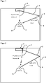
- FIG 1 shows a schematic representation of a speaker system 1 of the prior art for generating surround sound.
- An output signal 5 is generated by a non-frontally radiating loudspeaker, which is reflected on a wall 8 6 and is intended to give a listener 9 in the listening area 11 the feeling that the sound source is at the point of reflection.
- an undesired direct sound 7 is also generated by the non-frontally radiating loudspeaker, which reaches a listener 9 in the listening area 11 because of the shorter path in front of the reflected sound 6 . Due to the Haas effect, the listener 9 will locate the sound source based on the direct sound. The spatial sound experience to be generated by the reflected sound 6 is thus marred.
- FIG 2 shows an identical prior art speaker system 1 .
- a loudspeaker 3 oriented in the direction of the wall 8 and not radiating frontally is also shown here.
- figure 3 shows the basic principle of the attenuation of undesired direct sound 7.
- the constellation known from the prior art for generating surround sound is shown once again, in which undesired direct sound 7 also arises.
- the loudspeaker system 1 on the right-hand side also has a front loudspeaker 13 , the output signal 15 of which contains an attenuation signal which, through appropriate adjustment, attenuates the undesired direct sound 7 so that only a heavily attenuated sound signal 17 from this arrives at a listener 9 in the listener area 11 .
- the listener essentially only reaches the desired, reflected sound 6 from a surround sound channel of a loudspeaker 3 that does not radiate from the front.
- FIG 4 shows schematically the structure of the loudspeaker system, the high-pass filter connected upstream of the FIR filter according to the invention not being shown.
- An electronic signal 19 of a surround sound channel is divided at a signal splitter 21 and fed to an FIR filter 23 in a signal arm, which is connected upstream of a front speaker 13 .
- the electronic signal 19 of the surround sound channel is adjusted by the FIR filter following filtering by the high-pass filter (not shown) in such a way that the front loudspeaker 13 generates an output signal which is used to attenuate the direct sound.
- the electronic signal 19 of the surround sound channel in the other signal arm is time-adjusted by a delay element 25 before it is fed to a loudspeaker 3 that does not radiate frontally.
- a delay element 25 This allows the output signal of the non-frontally radiating loudspeaker 3 to be adjusted over time, which takes into account the latency of the FIR filter 23 and the different propagation times of the direct sound and the output signal of the non-frontally radiating loudspeaker 3 .
- the direct sound and the associated attenuation signal can be brought into a temporal correspondence required for the destructive interference.
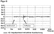
- figure 5 shows a measurement in a listening area of reflected sound and direct sound as a function of time with a pulse-like output signal from the non-frontally radiating loudspeaker. It can be seen that a considerable direct sound signal occurred before the reflected signal reaches the listening area. The resulting psychoacoustic Haas effect causes a listener to use the direction of the direct sound to locate the sound source. The spatial sound effect to be achieved by the reflected signal fizzles out.
- figure 6 shows the same measurement with simultaneous attenuation of the direct sound according to the invention. You can see that essentially no more direct sound is measured. The spatial sound effect is created.
Claims (12)
- Système de haut-parleurs (1) pour la reproduction d'au moins un canal, comprenantau moins un haut-parleur à rayonnement non frontal (3) et un canal associé au haut-parleur à rayonnement non frontal, qui est un canal de son ambiophonique,au moins un haut-parleur frontal (13),pour chaque canal de son ambiophonique, un filtre placé en amont du haut-parleur frontal (13) etpour chaque canal de son ambiophonique, au moins un élément de temporisation (25) placé en amont du haut-parleur à rayonnement non frontal (3),dans lequel le filtre est un filtre FIR (23) et l'élément de temporisation (25) et le filtre FIR (23) sont configurés pour un ajustement relatif des signaux de sortie (15, 5) du haut-parleur frontal (13) et du haut-parleur à rayonnement non frontal (3) du canal de son ambiophonique pour atténuer des bruits directs non souhaités (7) du haut-parleur à rayonnement non frontal (3) dans une zone d'écoute (11),caractérisé en ce queun filtre passe-haut est placé en amont du filtre FIR (23).
- Système de haut-parleurs (1) selon la revendication 1,
dans lequel au moins un filtre FIR (23) et/ou au moins un élément de temporisation (25) sont mis en œuvre par une puce DSP. - Système de haut-parleurs (1) selon une ou plusieurs des revendications précédentes,
dans lequel l'ajustement relatif des signaux de sortie (15, 5) du haut-parleur frontal (13) et du haut-parleur à rayonnement non frontal (3) est effectuée en ce qui concerne l'amplitude, la réponse en phase et la réponse en fréquence. - Système de haut-parleurs (1) selon une ou plusieurs des revendications précédentes,
dans lequel l'élément de temporisation (25) est configuré pour un retard pour compenser une latence du signal de sortie (15) du haut-parleur frontal (13) causée par le filtre FIR (23). - Système de haut-parleurs (1) selon une ou plusieurs des revendications précédentes,
dans lequel l'ajustement relatif des signaux de sortie (15, 5) du haut-parleur frontal (13) et du haut-parleur à rayonnement non frontal (3) pour atténuer les bruits directs non souhaités (7) provoque une interférence partiellement destructive entre le signal de sortie (15) du haut-parleur frontal (13) et les bruits directs non souhaités (7) du haut-parleur à rayonnement non frontal (3) dans la zone d'écoute (11). - Système de haut-parleurs (1) selon une ou plusieurs des revendications précédentes,
dans lequel l'ajustement relatif des signaux de sortie (15, 5) du haut-parleur frontal (13) et du haut-parleur à rayonnement non frontal (3) pour atténuer les bruits directs non souhaités (7) dans la zone d'écoute (11) concerne lesdits signaux de sortie (15, 5) dont les fréquences comprennent la plage des moyennes et hautes fréquences. - Système de haut-parleurs (1) selon une ou plusieurs des revendications précédentes,
dans lequel un canal est associé au haut-parleur frontal (13), dans lequel un signal d'un filtre FIR (23) est ajouté à un signal de canal pour produire le signal de sortie (15) du haut-parleur frontal. - Système de haut-parleur (1) selon une ou plusieurs des revendications précédentes,
dans lequel le filtre passe-haut présente de préférence une fréquence de coupure comprise entre 50 Hz et 200 Hz, en particulier entre 100 Hz et 150 Hz. - Système de haut-parleurs (1) selon une ou plusieurs des revendications précédentes,
dans lequel les haut-parleurs (3) à rayonnement non frontal comprennent des haut-parleurs latéraux et/ou des haut-parleurs de plafond. - Procédé d'atténuation de bruits directs non souhaités (7) d'au moins un haut-parleur à rayonnement non frontal (3) dans une zone d'écoute (11) pour un système de haut-parleurs (1) destiné à reproduire au moins un canal, de préférence selon une ou plusieurs des revendications 1 à 9,comprenantla fourniture d'au moins un haut-parleur à rayonnement non frontal (3) et un canal associé au haut-parleur à rayonnement non frontal (3), qui est un canal de son ambiophonique ;la fourniture d'au moins un haut-parleur frontal (13) ;la fourniture d'un filtre placé en amont du haut-parleur frontal (13) pour chaque canal de son ambiophonique ;la fourniture d'au moins un élément de temporisation (25) placé en amont du haut-parleur à rayonnement non frontal (3) pour chaque canal de son ambiophonique,dans lequel le filtre est un filtre FIR (23) et l'élément de temporisation (25) et le filtre FIR (23) sont configurés pour un ajustement relatif des signaux de sortie (15, 5) du haut-parleur frontal (13) et d'au moins un haut-parleur à rayonnement non frontal (3) d'un canal de son ambiophonique pour atténuer des bruits directs non souhaités (7) du haut-parleur à rayonnement non frontal (3) dans une zone d'écoute (11),caractérisé en ce queun filtre passe-haut est placé en amont du filtre FIR (23).
- Procédé d'atténuation d'un signal de sortie non souhaité selon la revendication précédente,
dans lequel l'ajustement relatif des signaux de sortie (15, 5) du haut-parleur frontal (13) et du haut-parleur à rayonnement non frontal (3) est effectuée en ce qui concerne l'amplitude, la réponse en phase et la réponse en fréquence. - Procédé d'atténuation d'un signal de sortie non souhaité selon une ou plusieurs des revendications précédentes,
dans lequel l'ajustement relatif des signaux de sortie (15, 5) du haut-parleur frontal (13) et du haut-parleur à rayonnement non frontal (3) pour atténuer les bruits directs non souhaités (7) provoque une interférence partiellement destructive entre le signal de sortie (15) du haut-parleur frontal (13) et les bruits directs non souhaités (7) du haut-parleur à rayonnement non frontal (3) dans la zone d'écoute (11).
Applications Claiming Priority (2)
| Application Number | Priority Date | Filing Date | Title |
|---|---|---|---|
| DE102017119650 | 2017-08-28 | ||
| PCT/EP2018/073100 WO2019042978A1 (fr) | 2017-08-28 | 2018-08-28 | Système de haut-parleurs pour son ambiophonique avec suppression des bruits directs non souhaités |
Publications (2)
| Publication Number | Publication Date |
|---|---|
| EP3677053A1 EP3677053A1 (fr) | 2020-07-08 |
| EP3677053B1 true EP3677053B1 (fr) | 2022-07-13 |
Family
ID=63449452
Family Applications (1)
| Application Number | Title | Priority Date | Filing Date |
|---|---|---|---|
| EP18762485.3A Active EP3677053B1 (fr) | 2017-08-28 | 2018-08-28 | Système de haut-parleurs pour son ambiophonique avec suppression des bruits directs non souhaités |
Country Status (4)
| Country | Link |
|---|---|
| EP (1) | EP3677053B1 (fr) |
| DE (1) | DE102018120958A1 (fr) |
| PL (1) | PL3677053T3 (fr) |
| WO (1) | WO2019042978A1 (fr) |
Families Citing this family (4)
| Publication number | Priority date | Publication date | Assignee | Title |
|---|---|---|---|---|
| CN112672084A (zh) * | 2019-10-15 | 2021-04-16 | 海信视像科技股份有限公司 | 显示装置及扬声器音效调整方法 |
| US11271607B2 (en) | 2019-11-06 | 2022-03-08 | Rohde & Schwarz Gmbh & Co. Kg | Test system and method for testing a transmission path of a cable connection between a first and a second position |
| US11741093B1 (en) | 2021-07-21 | 2023-08-29 | T-Mobile Usa, Inc. | Intermediate communication layer to translate a request between a user of a database and the database |
| US11924711B1 (en) | 2021-08-20 | 2024-03-05 | T-Mobile Usa, Inc. | Self-mapping listeners for location tracking in wireless personal area networks |
Family Cites Families (4)
| Publication number | Priority date | Publication date | Assignee | Title |
|---|---|---|---|---|
| US5815578A (en) * | 1997-01-17 | 1998-09-29 | Aureal Semiconductor, Inc. | Method and apparatus for canceling leakage from a speaker |
| US7606377B2 (en) * | 2006-05-12 | 2009-10-20 | Cirrus Logic, Inc. | Method and system for surround sound beam-forming using vertically displaced drivers |
| TWI635753B (zh) * | 2013-01-07 | 2018-09-11 | 美商杜比實驗室特許公司 | 使用向上發聲驅動器之用於反射聲音呈現的虛擬高度濾波器 |
| CN108141687B (zh) * | 2015-08-21 | 2021-06-29 | Dts(英属维尔京群岛)有限公司 | 用于泄漏消除的多扬声器方法和装置 |
-
2018
- 2018-08-28 PL PL18762485.3T patent/PL3677053T3/pl unknown
- 2018-08-28 WO PCT/EP2018/073100 patent/WO2019042978A1/fr active Search and Examination
- 2018-08-28 DE DE102018120958.4A patent/DE102018120958A1/de not_active Ceased
- 2018-08-28 EP EP18762485.3A patent/EP3677053B1/fr active Active
Also Published As
| Publication number | Publication date |
|---|---|
| WO2019042978A1 (fr) | 2019-03-07 |
| PL3677053T3 (pl) | 2022-10-10 |
| DE102018120958A1 (de) | 2019-02-28 |
| EP3677053A1 (fr) | 2020-07-08 |
Similar Documents
| Publication | Publication Date | Title |
|---|---|---|
| EP3677053B1 (fr) | Système de haut-parleurs pour son ambiophonique avec suppression des bruits directs non souhaités | |
| EP3152925B1 (fr) | Système de haut-parleur | |
| DE2910117C2 (de) | Lautsprecherkombination zur Wiedergabe eines zwei- oder mehrkanalig übertragenen Schallereignisses | |
| DE1812596C3 (de) | Lautsprechersystem für Stereoübertragung in geschlossenen Räumen | |
| EP3005732B1 (fr) | Dispositif et procédé de restitution audio à sélectivité spatiale | |
| DE102005003431B4 (de) | Anordnung zum Wiedergeben von binauralen Signalen (Kunstkopfsignalen) durch mehrere Lautsprecher | |
| DE3839702A1 (de) | Vorrichtung zur stereofonen, elektroakustischen signalwandlung | |
| DE102005001395A1 (de) | Transformation des frühen Schallfeldes | |
| EP0040739B1 (fr) | Dispositif pour la reproduction par écouteurs d'un enregistrement sonore | |
| DE4033068C2 (de) | Fernsehempfangsgerät mit Stereotonwiedergabe | |
| DE2941692A1 (de) | Verfahren und vorrichtung zur tonwiedergabe | |
| EP3314915A1 (fr) | Procédé de reproduction sonore dans des environnements réfléchissants, en particulier dans des salles d'écoute | |
| WO1995030323A1 (fr) | Procede et dispositif pour la compensation de falsifications acoustiques | |
| DE19639159C2 (de) | Lautsprecherbox | |
| DE3041429A1 (en) | Dimensional sound producing apparatus and method | |
| EP0025118A1 (fr) | Dispositif pour la reproduction acoustique de signaux qui sont représentables au moyen de canaux stéréophoniques de droite et de gauche | |
| DE102011108788B4 (de) | Verfahren zur Verarbeitung eines Audiosignals, Audiowiedergabesystem und Verarbeitungseinheit zur Bearbeitung von Audiosignalen | |
| WO2007110087A1 (fr) | Dispositif pour la reproduction de signaux binauraux (signaux de casque d'ecouteur) par plusieurs haut-parleurs | |
| DE102018108852B3 (de) | Verfahren zur Beeinflussung einer auditiven Richtungswahrnehmung eines Hörers | |
| DE3132250A1 (de) | "lautsprecherbox" | |
| EP1900250B1 (fr) | Procede electro-acoustique | |
| AT391389B (de) | Elektroakustische anordnung zur darbietung von audiosignalen fuer das richtungsorientierte raeumliche hoeren bei binauraler wiedergabe | |
| AT357208B (de) | Anordnung zur wiedergabe wenigstens zweikanalig uebertragener schallereignisse in geschlossenen raeumen | |
| DE2933842A1 (de) | Elektroakustisches wiedergabesystem | |
| DE19514105A1 (de) | Kopfhörer-Raumklanganpassungsschaltung |
Legal Events
| Date | Code | Title | Description |
|---|---|---|---|
| STAA | Information on the status of an ep patent application or granted ep patent |
Free format text: STATUS: UNKNOWN |
|
| STAA | Information on the status of an ep patent application or granted ep patent |
Free format text: STATUS: THE INTERNATIONAL PUBLICATION HAS BEEN MADE |
|
| PUAI | Public reference made under article 153(3) epc to a published international application that has entered the european phase |
Free format text: ORIGINAL CODE: 0009012 |
|
| STAA | Information on the status of an ep patent application or granted ep patent |
Free format text: STATUS: REQUEST FOR EXAMINATION WAS MADE |
|
| 17P | Request for examination filed |
Effective date: 20200218 |
|
| AK | Designated contracting states |
Kind code of ref document: A1 Designated state(s): AL AT BE BG CH CY CZ DE DK EE ES FI FR GB GR HR HU IE IS IT LI LT LU LV MC MK MT NL NO PL PT RO RS SE SI SK SM TR |
|
| AX | Request for extension of the european patent |
Extension state: BA ME |
|
| DAV | Request for validation of the european patent (deleted) | ||
| DAX | Request for extension of the european patent (deleted) | ||
| STAA | Information on the status of an ep patent application or granted ep patent |
Free format text: STATUS: EXAMINATION IS IN PROGRESS |
|
| 17Q | First examination report despatched |
Effective date: 20210701 |
|
| GRAP | Despatch of communication of intention to grant a patent |
Free format text: ORIGINAL CODE: EPIDOSNIGR1 |
|
| STAA | Information on the status of an ep patent application or granted ep patent |
Free format text: STATUS: GRANT OF PATENT IS INTENDED |
|
| INTG | Intention to grant announced |
Effective date: 20220209 |
|
| GRAS | Grant fee paid |
Free format text: ORIGINAL CODE: EPIDOSNIGR3 |
|
| GRAA | (expected) grant |
Free format text: ORIGINAL CODE: 0009210 |
|
| STAA | Information on the status of an ep patent application or granted ep patent |
Free format text: STATUS: THE PATENT HAS BEEN GRANTED |
|
| AK | Designated contracting states |
Kind code of ref document: B1 Designated state(s): AL AT BE BG CH CY CZ DE DK EE ES FI FR GB GR HR HU IE IS IT LI LT LU LV MC MK MT NL NO PL PT RO RS SE SI SK SM TR |
|
| REG | Reference to a national code |
Ref country code: CH Ref legal event code: EP |
|
| REG | Reference to a national code |
Ref country code: DE Ref legal event code: R096 Ref document number: 502018010152 Country of ref document: DE |
|
| REG | Reference to a national code |
Ref country code: AT Ref legal event code: REF Ref document number: 1504888 Country of ref document: AT Kind code of ref document: T Effective date: 20220815 |
|
| REG | Reference to a national code |
Ref country code: IE Ref legal event code: FG4D Free format text: LANGUAGE OF EP DOCUMENT: GERMAN |
|
| REG | Reference to a national code |
Ref country code: NL Ref legal event code: FP |
|
| REG | Reference to a national code |
Ref country code: LT Ref legal event code: MG9D |
|
| PG25 | Lapsed in a contracting state [announced via postgrant information from national office to epo] |
Ref country code: SE Free format text: LAPSE BECAUSE OF FAILURE TO SUBMIT A TRANSLATION OF THE DESCRIPTION OR TO PAY THE FEE WITHIN THE PRESCRIBED TIME-LIMIT Effective date: 20220713 Ref country code: RS Free format text: LAPSE BECAUSE OF FAILURE TO SUBMIT A TRANSLATION OF THE DESCRIPTION OR TO PAY THE FEE WITHIN THE PRESCRIBED TIME-LIMIT Effective date: 20220713 Ref country code: PT Free format text: LAPSE BECAUSE OF FAILURE TO SUBMIT A TRANSLATION OF THE DESCRIPTION OR TO PAY THE FEE WITHIN THE PRESCRIBED TIME-LIMIT Effective date: 20221114 Ref country code: NO Free format text: LAPSE BECAUSE OF FAILURE TO SUBMIT A TRANSLATION OF THE DESCRIPTION OR TO PAY THE FEE WITHIN THE PRESCRIBED TIME-LIMIT Effective date: 20221013 Ref country code: LV Free format text: LAPSE BECAUSE OF FAILURE TO SUBMIT A TRANSLATION OF THE DESCRIPTION OR TO PAY THE FEE WITHIN THE PRESCRIBED TIME-LIMIT Effective date: 20220713 Ref country code: LT Free format text: LAPSE BECAUSE OF FAILURE TO SUBMIT A TRANSLATION OF THE DESCRIPTION OR TO PAY THE FEE WITHIN THE PRESCRIBED TIME-LIMIT Effective date: 20220713 Ref country code: FI Free format text: LAPSE BECAUSE OF FAILURE TO SUBMIT A TRANSLATION OF THE DESCRIPTION OR TO PAY THE FEE WITHIN THE PRESCRIBED TIME-LIMIT Effective date: 20220713 Ref country code: ES Free format text: LAPSE BECAUSE OF FAILURE TO SUBMIT A TRANSLATION OF THE DESCRIPTION OR TO PAY THE FEE WITHIN THE PRESCRIBED TIME-LIMIT Effective date: 20220713 |
|
| PG25 | Lapsed in a contracting state [announced via postgrant information from national office to epo] |
Ref country code: IS Free format text: LAPSE BECAUSE OF FAILURE TO SUBMIT A TRANSLATION OF THE DESCRIPTION OR TO PAY THE FEE WITHIN THE PRESCRIBED TIME-LIMIT Effective date: 20221113 Ref country code: HR Free format text: LAPSE BECAUSE OF FAILURE TO SUBMIT A TRANSLATION OF THE DESCRIPTION OR TO PAY THE FEE WITHIN THE PRESCRIBED TIME-LIMIT Effective date: 20220713 Ref country code: GR Free format text: LAPSE BECAUSE OF FAILURE TO SUBMIT A TRANSLATION OF THE DESCRIPTION OR TO PAY THE FEE WITHIN THE PRESCRIBED TIME-LIMIT Effective date: 20221014 |
|
| REG | Reference to a national code |
Ref country code: DE Ref legal event code: R097 Ref document number: 502018010152 Country of ref document: DE |
|
| PG25 | Lapsed in a contracting state [announced via postgrant information from national office to epo] |
Ref country code: SM Free format text: LAPSE BECAUSE OF FAILURE TO SUBMIT A TRANSLATION OF THE DESCRIPTION OR TO PAY THE FEE WITHIN THE PRESCRIBED TIME-LIMIT Effective date: 20220713 Ref country code: RO Free format text: LAPSE BECAUSE OF FAILURE TO SUBMIT A TRANSLATION OF THE DESCRIPTION OR TO PAY THE FEE WITHIN THE PRESCRIBED TIME-LIMIT Effective date: 20220713 Ref country code: MC Free format text: LAPSE BECAUSE OF FAILURE TO SUBMIT A TRANSLATION OF THE DESCRIPTION OR TO PAY THE FEE WITHIN THE PRESCRIBED TIME-LIMIT Effective date: 20220713 Ref country code: LU Free format text: LAPSE BECAUSE OF NON-PAYMENT OF DUE FEES Effective date: 20220828 Ref country code: DK Free format text: LAPSE BECAUSE OF FAILURE TO SUBMIT A TRANSLATION OF THE DESCRIPTION OR TO PAY THE FEE WITHIN THE PRESCRIBED TIME-LIMIT Effective date: 20220713 Ref country code: CZ Free format text: LAPSE BECAUSE OF FAILURE TO SUBMIT A TRANSLATION OF THE DESCRIPTION OR TO PAY THE FEE WITHIN THE PRESCRIBED TIME-LIMIT Effective date: 20220713 |
|
| REG | Reference to a national code |
Ref country code: BE Ref legal event code: MM Effective date: 20220831 |
|
| PLBE | No opposition filed within time limit |
Free format text: ORIGINAL CODE: 0009261 |
|
| STAA | Information on the status of an ep patent application or granted ep patent |
Free format text: STATUS: NO OPPOSITION FILED WITHIN TIME LIMIT |
|
| PG25 | Lapsed in a contracting state [announced via postgrant information from national office to epo] |
Ref country code: SK Free format text: LAPSE BECAUSE OF FAILURE TO SUBMIT A TRANSLATION OF THE DESCRIPTION OR TO PAY THE FEE WITHIN THE PRESCRIBED TIME-LIMIT Effective date: 20220713 Ref country code: EE Free format text: LAPSE BECAUSE OF FAILURE TO SUBMIT A TRANSLATION OF THE DESCRIPTION OR TO PAY THE FEE WITHIN THE PRESCRIBED TIME-LIMIT Effective date: 20220713 |
|
| 26N | No opposition filed |
Effective date: 20230414 |
|
| P01 | Opt-out of the competence of the unified patent court (upc) registered |
Effective date: 20230515 |
|
| GBPC | Gb: european patent ceased through non-payment of renewal fee |
Effective date: 20221013 |
|
| PG25 | Lapsed in a contracting state [announced via postgrant information from national office to epo] |
Ref country code: AL Free format text: LAPSE BECAUSE OF FAILURE TO SUBMIT A TRANSLATION OF THE DESCRIPTION OR TO PAY THE FEE WITHIN THE PRESCRIBED TIME-LIMIT Effective date: 20220713 |
|
| PG25 | Lapsed in a contracting state [announced via postgrant information from national office to epo] |
Ref country code: IE Free format text: LAPSE BECAUSE OF NON-PAYMENT OF DUE FEES Effective date: 20220828 |
|
| PG25 | Lapsed in a contracting state [announced via postgrant information from national office to epo] |
Ref country code: SI Free format text: LAPSE BECAUSE OF FAILURE TO SUBMIT A TRANSLATION OF THE DESCRIPTION OR TO PAY THE FEE WITHIN THE PRESCRIBED TIME-LIMIT Effective date: 20220713 |
|
| PG25 | Lapsed in a contracting state [announced via postgrant information from national office to epo] |
Ref country code: BE Free format text: LAPSE BECAUSE OF NON-PAYMENT OF DUE FEES Effective date: 20220831 |
|
| PGFP | Annual fee paid to national office [announced via postgrant information from national office to epo] |
Ref country code: NL Payment date: 20230823 Year of fee payment: 6 |
|
| PG25 | Lapsed in a contracting state [announced via postgrant information from national office to epo] |
Ref country code: GB Free format text: LAPSE BECAUSE OF NON-PAYMENT OF DUE FEES Effective date: 20221013 |
|
| PGFP | Annual fee paid to national office [announced via postgrant information from national office to epo] |
Ref country code: CH Payment date: 20230902 Year of fee payment: 6 Ref country code: AT Payment date: 20230818 Year of fee payment: 6 |
|
| PGFP | Annual fee paid to national office [announced via postgrant information from national office to epo] |
Ref country code: PL Payment date: 20230817 Year of fee payment: 6 Ref country code: FR Payment date: 20230821 Year of fee payment: 6 Ref country code: DE Payment date: 20230801 Year of fee payment: 6 |
|
| PG25 | Lapsed in a contracting state [announced via postgrant information from national office to epo] |
Ref country code: IT Free format text: LAPSE BECAUSE OF FAILURE TO SUBMIT A TRANSLATION OF THE DESCRIPTION OR TO PAY THE FEE WITHIN THE PRESCRIBED TIME-LIMIT Effective date: 20220713 |
|
| PG25 | Lapsed in a contracting state [announced via postgrant information from national office to epo] |
Ref country code: CY Free format text: LAPSE BECAUSE OF FAILURE TO SUBMIT A TRANSLATION OF THE DESCRIPTION OR TO PAY THE FEE WITHIN THE PRESCRIBED TIME-LIMIT Effective date: 20220713 |