EP3676010B1 - An injection molded microfluidic/fluidic cartridge integrated with silicon-based sensor - Google Patents
An injection molded microfluidic/fluidic cartridge integrated with silicon-based sensor Download PDFInfo
- Publication number
- EP3676010B1 EP3676010B1 EP18852532.3A EP18852532A EP3676010B1 EP 3676010 B1 EP3676010 B1 EP 3676010B1 EP 18852532 A EP18852532 A EP 18852532A EP 3676010 B1 EP3676010 B1 EP 3676010B1
- Authority
- EP
- European Patent Office
- Prior art keywords
- channel
- input
- output
- sensor
- microfluidic device
- Prior art date
- Legal status (The legal status is an assumption and is not a legal conclusion. Google has not performed a legal analysis and makes no representation as to the accuracy of the status listed.)
- Active
Links
Images


Classifications
-
- B—PERFORMING OPERATIONS; TRANSPORTING
- B01—PHYSICAL OR CHEMICAL PROCESSES OR APPARATUS IN GENERAL
- B01L—CHEMICAL OR PHYSICAL LABORATORY APPARATUS FOR GENERAL USE
- B01L3/00—Containers or dishes for laboratory use, e.g. laboratory glassware; Droppers
- B01L3/50—Containers for the purpose of retaining a material to be analysed, e.g. test tubes
- B01L3/502—Containers for the purpose of retaining a material to be analysed, e.g. test tubes with fluid transport, e.g. in multi-compartment structures
- B01L3/5027—Containers for the purpose of retaining a material to be analysed, e.g. test tubes with fluid transport, e.g. in multi-compartment structures by integrated microfluidic structures, i.e. dimensions of channels and chambers are such that surface tension forces are important, e.g. lab-on-a-chip
- B01L3/502715—Containers for the purpose of retaining a material to be analysed, e.g. test tubes with fluid transport, e.g. in multi-compartment structures by integrated microfluidic structures, i.e. dimensions of channels and chambers are such that surface tension forces are important, e.g. lab-on-a-chip characterised by interfacing components, e.g. fluidic, electrical, optical or mechanical interfaces
-
- B—PERFORMING OPERATIONS; TRANSPORTING
- B01—PHYSICAL OR CHEMICAL PROCESSES OR APPARATUS IN GENERAL
- B01L—CHEMICAL OR PHYSICAL LABORATORY APPARATUS FOR GENERAL USE
- B01L3/00—Containers or dishes for laboratory use, e.g. laboratory glassware; Droppers
- B01L3/50—Containers for the purpose of retaining a material to be analysed, e.g. test tubes
- B01L3/502—Containers for the purpose of retaining a material to be analysed, e.g. test tubes with fluid transport, e.g. in multi-compartment structures
- B01L3/5027—Containers for the purpose of retaining a material to be analysed, e.g. test tubes with fluid transport, e.g. in multi-compartment structures by integrated microfluidic structures, i.e. dimensions of channels and chambers are such that surface tension forces are important, e.g. lab-on-a-chip
- B01L3/502738—Containers for the purpose of retaining a material to be analysed, e.g. test tubes with fluid transport, e.g. in multi-compartment structures by integrated microfluidic structures, i.e. dimensions of channels and chambers are such that surface tension forces are important, e.g. lab-on-a-chip characterised by integrated valves
-
- B—PERFORMING OPERATIONS; TRANSPORTING
- B01—PHYSICAL OR CHEMICAL PROCESSES OR APPARATUS IN GENERAL
- B01L—CHEMICAL OR PHYSICAL LABORATORY APPARATUS FOR GENERAL USE
- B01L2200/00—Solutions for specific problems relating to chemical or physical laboratory apparatus
- B01L2200/02—Adapting objects or devices to another
- B01L2200/026—Fluid interfacing between devices or objects, e.g. connectors, inlet details
- B01L2200/027—Fluid interfacing between devices or objects, e.g. connectors, inlet details for microfluidic devices
-
- B—PERFORMING OPERATIONS; TRANSPORTING
- B01—PHYSICAL OR CHEMICAL PROCESSES OR APPARATUS IN GENERAL
- B01L—CHEMICAL OR PHYSICAL LABORATORY APPARATUS FOR GENERAL USE
- B01L2200/00—Solutions for specific problems relating to chemical or physical laboratory apparatus
- B01L2200/06—Fluid handling related problems
- B01L2200/0689—Sealing
-
- B—PERFORMING OPERATIONS; TRANSPORTING
- B01—PHYSICAL OR CHEMICAL PROCESSES OR APPARATUS IN GENERAL
- B01L—CHEMICAL OR PHYSICAL LABORATORY APPARATUS FOR GENERAL USE
- B01L2300/00—Additional constructional details
- B01L2300/06—Auxiliary integrated devices, integrated components
- B01L2300/0627—Sensor or part of a sensor is integrated
- B01L2300/0663—Whole sensors
-
- B—PERFORMING OPERATIONS; TRANSPORTING
- B01—PHYSICAL OR CHEMICAL PROCESSES OR APPARATUS IN GENERAL
- B01L—CHEMICAL OR PHYSICAL LABORATORY APPARATUS FOR GENERAL USE
- B01L2300/00—Additional constructional details
- B01L2300/08—Geometry, shape and general structure
- B01L2300/0861—Configuration of multiple channels and/or chambers in a single devices
- B01L2300/0877—Flow chambers
-
- B—PERFORMING OPERATIONS; TRANSPORTING
- B01—PHYSICAL OR CHEMICAL PROCESSES OR APPARATUS IN GENERAL
- B01L—CHEMICAL OR PHYSICAL LABORATORY APPARATUS FOR GENERAL USE
- B01L2300/00—Additional constructional details
- B01L2300/08—Geometry, shape and general structure
- B01L2300/0887—Laminated structure
-
- B—PERFORMING OPERATIONS; TRANSPORTING
- B01—PHYSICAL OR CHEMICAL PROCESSES OR APPARATUS IN GENERAL
- B01L—CHEMICAL OR PHYSICAL LABORATORY APPARATUS FOR GENERAL USE
- B01L2300/00—Additional constructional details
- B01L2300/12—Specific details about materials
- B01L2300/123—Flexible; Elastomeric
-
- B—PERFORMING OPERATIONS; TRANSPORTING
- B01—PHYSICAL OR CHEMICAL PROCESSES OR APPARATUS IN GENERAL
- B01L—CHEMICAL OR PHYSICAL LABORATORY APPARATUS FOR GENERAL USE
- B01L2400/00—Moving or stopping fluids
- B01L2400/02—Drop detachment mechanisms of single droplets from nozzles or pins
- B01L2400/027—Drop detachment mechanisms of single droplets from nozzles or pins electrostatic forces between substrate and tip
-
- B—PERFORMING OPERATIONS; TRANSPORTING
- B01—PHYSICAL OR CHEMICAL PROCESSES OR APPARATUS IN GENERAL
- B01L—CHEMICAL OR PHYSICAL LABORATORY APPARATUS FOR GENERAL USE
- B01L2400/00—Moving or stopping fluids
- B01L2400/04—Moving fluids with specific forces or mechanical means
- B01L2400/0475—Moving fluids with specific forces or mechanical means specific mechanical means and fluid pressure
- B01L2400/0487—Moving fluids with specific forces or mechanical means specific mechanical means and fluid pressure fluid pressure, pneumatics
- B01L2400/049—Moving fluids with specific forces or mechanical means specific mechanical means and fluid pressure fluid pressure, pneumatics vacuum
-
- B—PERFORMING OPERATIONS; TRANSPORTING
- B01—PHYSICAL OR CHEMICAL PROCESSES OR APPARATUS IN GENERAL
- B01L—CHEMICAL OR PHYSICAL LABORATORY APPARATUS FOR GENERAL USE
- B01L2400/00—Moving or stopping fluids
- B01L2400/06—Valves, specific forms thereof
-
- B—PERFORMING OPERATIONS; TRANSPORTING
- B01—PHYSICAL OR CHEMICAL PROCESSES OR APPARATUS IN GENERAL
- B01L—CHEMICAL OR PHYSICAL LABORATORY APPARATUS FOR GENERAL USE
- B01L2400/00—Moving or stopping fluids
- B01L2400/06—Valves, specific forms thereof
- B01L2400/0633—Valves, specific forms thereof with moving parts
- B01L2400/0655—Valves, specific forms thereof with moving parts pinch valves
Definitions
- WO 2015/138648 A1 describes a complementary metal-oxide-semiconductor biosensor device comprising a flow cell lid made from cyclic olefin polymer with a recessed cavity on one side which is closed with a laminate film including the complementary metal-oxide-semiconductor biosensor device to form a flow cell, where input and output ports are formed as holes in the lid.
- US 2012/315191 A1 describes a microchannel chip.
- microfluidic device as specified by claim 1.
- the invention provides a method of flowing a sample through a microfluidic device, as specified by claim 23. Further features of the invention are defined in the dependent claims.
- Exemplary microfluidic device include a substrate, a sensor, and one or more lamination films.
- the top surface of the substrate can include first recessed grooves forming first open channels and the bottom surface of the plastic substrate can include a first recessed cavity and second recessed groves forming second open channels.
- a first lamination film can be adhered with the top surface of the plastic substrate to form first closed channels.
- a second lamination film can be adhered to the bottom surface of the plastic substrate to form second closed channels.
- microfluidic devices that include a plastic substrate having a first surface and a second surface, where the first and second surfaces are disposed on opposite sides of the plastic substrate.
- a microfluidic device can also include a sensor having a first surface and a second surface, where the first surface has an electronic circuit layer.
- a microfluidic device can further include a lamination film.
- the first surface of the plastic substrate can have an input recessed groove and an output recessed groove.
- the second surface of the plastic substrate can have a recessed cavity.
- the lamination film can be adhered to the first surface of the plastic substrate and can cover the input recessed groove and the output recessed groove, such that an input closed channel is formed by the lamination film and the input recessed groove and an output closed channel is formed by the lamination film and the output recessed groove.
- the sensor can cover the recessed cavity, such that a flow cell is formed by the first surface of the sensor and the recessed cavity.
- the input closed channel can be fluidly connected with the flow cell
- the output closed channel can be fluidly connected with the flow cell.
- a device can include an elastomer spacer disposed in the recessed cavity between the substrate and the sensor, such that the flow cell is formed by the first surface of the sensor, the recessed cavity, and the elastomer spacer.
- an elastomer spacer can provide space between the first surface of the sensor and the second surface of the substrate.
- the depth of the flow cell can be defined by the thickness of the elastomer spacer after assembling.
- a microfluidic device can further include a valve assembly that controls flow through the input closed channel and the output closed channel.
- the valve assembly can include a manifold having an input control aperture and an output control aperture, an elastomeric sheet disposed between the manifold and the upper surface of the plastic substrate, and a raised structure extending from the upper surface of the plastic substrate toward the elastomeric sheet.
- the raised structure can have an input proximal ridge, an input distal ridge, an input stem positioned between the input proximal ridge and the input distal ridge, an output proximal ridge, an output distal ridge, and an output stem positioned between the output proximal ridge and the output distal ridge.
- the elastomeric sheet contacts the input and output stems when the elastomeric sheet is in a default sealing configuration, thereby preventing fluid communication between the input distal channel and the input proximal channel and between the output distal channel and the output proximal channel.
- the contact sheet is separated from the input stem when a negative pressure is present in the input control aperture, thereby allowing fluid communication between the input distal channel and the input proximal channel.
- the contact sheets is separated from the output stem when a negative pressure is present in the output control aperture, thereby allowing fluid communication between the output distal channel and the output proximal channel.
- An exemplary valve assembly includes a raise structure, a manifold, and an elastomeric sheet.
- the raised structure can have a floor, a proximal ridge extending from the floor, a distal ridge extending from the floor, and a stem extending from the floor.
- the stem can be positioned between the proximal ridge and the distal ridge.
- the manifold can have a control aperture.
- the elastomeric sheet can be disposed between the raised structure and the manifold.
- a valve assembly can further include a pressure source in fluid communication with the control aperture.
- the pressure source can be a positive pressure source.
- a valve assembly can further include a bolt, the manifold can have an aperture that receives the bolt, and the bolt can operate to compress the elastomeric sheet between the manifold and the proximal and distal ridges.
- a valve assembly can further include a snap clamp, and the snap clamp can operate to compress the elastomeric sheet between the manifold and the proximal and distal ridges.
- the distal channel is in fluid communication with a channel of the microfluidic device.
- Sequencing of the target DNA sequences occurs through multiple cycles, each cycle involving flowing sequencing reagents from the input channel into the flow cell, detecting a signal resulting from an interaction of the sequencing reagents and the target DNAs, and flowing reaction and waste products out of the flow cell through the output channel.
- a set of secondary channels can each supply different reagents to a common channel, such as to perform different assays in a single flow cell or to provide different combinations of reagents to a single flow cell.
- Each secondary channel can be coupled to the common channel by a membrane valve, thus permitting easy control over which secondary channel or combination of secondary channels is fluidically coupled to the common channel at any given time.
- Fluid driving pressure can be applied to convey fluid through the microfluidic device.
- Such fluid driving pressure can be positive pressure or negative pressure.
- positive pressure generators can include pumps (e.g., liquid pump, pneumatic pump), gravity-fed devices, or other such devices.
- negative pressure generators can include vacuums, pumps, or other such devices.
- the flow cell can be bounded at least in part by the sensor. In some cases, the flow cell can rest entirely within the boundary of the sensor. In some cases, the flow cell can extend beyond the boundary of the sensor, which can help maximize the available sensor surface area usable to detect data. In some cases, the flow cell can be bounded at least in part by two or more sensors. In such cases, the additional sensors can provide more resolution, can provide more throughput, can enable different types of assays, and/or can permit the use of smaller, cheaper sensors to achieve the same result. In some cases, the ability to use multiple sensors in a flow cell can be inherent to the design of the substrate, with only changes to the printed circuit board necessary to achieve different numbers of sensors. Thus, manufacturing of different types of microfluidic devices (e.g., single-sensor, multi-sensor, high-resolution) can be achieved using the same substrate and different printed circuit boards.
- microfluidic devices e.g., single-sensor, multi-sensor, high-resolution
- FIG. 1 is a cross-sectional view depicting aspects of an injection molded microfluidic cartridge integrated with a silicon-based sensor according to certain aspects of the present disclosure.
- a microfluidic device 100 includes a substrate 110, a sensor 120, and a lamination film 130.
- a lamination film can include a material such as cyclo olefin polymer (COP), polymethyl methacrylate (PMMA), polycarbonate (PC), polypropylene (PP), cyclic olefin copolymer (COC) and the like.
- COP cyclo olefin polymer
- PMMA polymethyl methacrylate
- PC polycarbonate
- PP polypropylene
- COC cyclic olefin copolymer
- a lamination method can be performed by thermal lamination by providing heat to a certain temperature (usually above the glass transition point of the lamination material chosen).
- the microfluidic device 100 can operate in a manner whereby sensor data transfer speeds are not compromised.
- the attachment process does not operate to interfere with an electric connection between a sensor and a printed circuit board (PCB).
- PCB printed circuit board
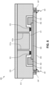
- a printed circuit board (PCB) 340 can be coupled with the substrate 310 and/or the sensor 320.
- sensor 320 can be wire bonded (e.g. with one or more wire bonds 342) with the PCB 340 to provide an electronic connection there between.
- the substrate 310 can include a recess 318 that receives or houses the wire bond 342. This feature can operate to help protect the wire bond 342 from damage during assembly of the microfluidic cartridge substrate 310 and the silicon-based sensor 320.
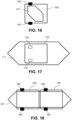
- Device 500 also includes a lamination film 530 that can function to provide one or more microfluidic channels 512 on the lower surface of the substrate 510.
- a microfluidic channel 512 disposed on the lower surface of the substrate 510 can be in fluid communication with a microfluidic channel associated with the raised structure 550 via an aperture 514.
- a valve assembly 580 can include a raised structure 582 having a floor 583, a proximal ridge 584 extending from the floor, a distal ridge 586 extending from the floor, and a stem 588 extending from the floor.
- the stem 588 is positioned between the proximal ridge 584 and the distal ridge 586.
- the valve assembly 580 can also include the manifold 570, and the manifold includes a control aperture 572 extending there through.
- the valve assembly 580 can also include the elastomeric sheet 560, and the elastomeric sheet 560 can be disposed between the raised structure 582 and the manifold 570.
- the secondary channel 954 is described as coupling a valve 966 with an inlet 953. In such cases, fluid flow may pass from the inlet 953, through the secondary channel 954, and out into the common channel 956. However, in some cases, the secondary channel 954 can instead couple the valve 966 with an outlet, in which case the fluid flow may pass from the common channel 956 into the secondary channel 954 and out the outlet.
- An array 900 can include only secondary channel groups 955 associated with inlets 953, only secondary channel groups 955 associated with outlets, or a combination of secondary channel groups 955 associated with inlets 953 and secondary channel groups associated with outlets.
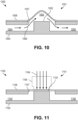
- a passage 1062 can be defined between the flexible membrane 1058 and the valve seat 1052.
- the passage 1062 can couple the first channel 1054 with the second channel 1056, permitting fluid flow 1060 between the channels.
- the flexible membrane 1058 naturally rests above the valve seat 1052 in a concave shape, although that need not always be the case (e.g., the flexible membrane 1058 can remain flat when the valve seat does not extend all the way to the top of the substrate 1050).
- the flexible membrane 1158 When the membrane valve 1100 is in a closed state, the flexible membrane 1158 can be compressed against the valve seat 1152, thus forming a fluidic seal between the first channel 1154 and the second channel 1156.
- the fluidic seal can completely block fluid flow between the channels or can be configured to reduce fluid flow between the channels.
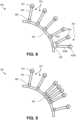
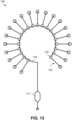
- FIG. 14 is a linear array 1400 of membrane valves 1466 for providing reagents to a flow cell 1417 according to certain aspects of the present disclosure.
- the linear array 1400 comprises a common channel 1456 that extends linearly or substantially linearly (e.g. along one or multiple straight lines or along nearly straight lines) along which a number of secondary channel groups 1455 can be located.
- the common channel 1456 can feed into a flow cell 1417, such as flow cell 117 of FIG. 1 , or any other suitable flow cell.
- common channel 1456 can be fluidically coupled with other elements instead of or in addition to a flow cell 1417.
- Each secondary channel group 1455 can be coupled to one or more reagents, which can be provided to the common channel 1456, and thus the flow cell 1417, individually or in any suitable combination or sequence.
- an ordered array of DNA binding regions is produced on or above a sensor, such as a CMOS sensor, that detects optical signals such as a fluorescence or luminescence signal.
- any reference to a series of examples is to be understood as a reference to each of those examples disjunctively (e.g., "Examples 1-4" is to be understood as “Examples 1, 2, 3, or 4").
- Example 1 is a microfluidic device comprising: a plastic substrate having a first surface and a second surface, the first and second surfaces disposed on opposite sides of the plastic substrate; a sensor having a first surface and a second surface, the first surface comprising an electronic circuit layer; and a lamination film; wherein the first surface of the plastic substrate comprises an input recessed groove and an output recessed groove, wherein the second surface of the plastic substrate comprises a recessed cavity, wherein the lamination film is adhered to the first surface of the plastic substrate and covers the input recessed groove and the output recessed groove, such that an input closed channel is formed by the lamination film and the input recessed groove and an output closed channel is formed by the lamination film and the output recessed groove, wherein the sensor covers the recessed cavity, such that a flow cell is formed by the first surface of the sensor and the recessed cavity, wherein the input closed channel is fluidly connected with the flow cell, and wherein the output closed channel is fluidly connected with the flow cell.
- Example 2 is the microfluidic device of example(s) 1, further comprising a second lamination film, wherein the second surface of the plastic substrate comprises a second input recessed groove and a second output recessed groove, wherein the second lamination film is adhered to the second surface of the plastic substrate and covers the input recessed groove and the output recessed groove, such that a second input closed channel is formed by the second lamination film and the second input recessed groove and a second output closed channel is formed by the second lamination film and the second output recessed groove, and wherein the input closed channel is fluidly connected with the second input closed channel and the output closed channel is fluidly connected with the second output closed channel, such that the input closed channel provides fluid communication between the second input closed channel and the flow cell and the output closed channel provides fluid communication between the second output closed channel and the flow cell.
- Example 4 is the microfluidic device of example(s) 1-3, wherein the plastic substrate comprises an injection molded plastic.
- Example 5 is the microfluidic device of example(s) 1-4, wherein the plastic substrate comprises a member selected from the group consisting of cyclic olefin polymer (COP), polymethyl methacrylate (PMMA), polycarbonate (PC), and polypropylene (PP).
- COP cyclic olefin polymer
- PMMA polymethyl methacrylate
- PC polycarbonate
- PP polypropylene
- Example 7 is the microfluidic device of example(s) 1-6, further comprising a printed circuit board coupled with the second surface of the sensor.
- Example 9 is the microfluidic device of example(s) 1-8, further comprising a valve assembly that controls flow through the input closed channel and the output closed channel, the valve assembly comprising: a manifold comprising an input control aperture and an output control aperture; an elastomeric sheet disposed between the manifold and the upper surface of the plastic substrate; and a raised structure extending from the upper surface of the plastic substrate toward the elastomeric sheet, the raised structure comprising an input proximal ridge, an input distal ridge, an input stem positioned between the input proximal ridge and the input distal ridge, an output proximal ridge, an output distal ridge, and an output stem positioned between the output proximal ridge and the output distal ridge, wherein the elastomeric sheet is compressed by the manifold against the input proximal and distal ridges and the output proximal and distal ridges, thereby forming an input proximal channel between the input proximal ridge and
- Example 11 is the microfluidic device of example(s) 10, wherein at least one of the set of secondary channel groups comprises an additional secondary channel fluidically coupling an additional reagent inlet to the valve.
- Example 13 is the microfluidic device of example(s) 10-12, wherein the set of secondary channel groups comprises a first subset of secondary channel groups and a second subset of secondary channel groups, wherein the first subset is distinct from the second subset, wherein the first subset of secondary channel groups is fluidically coupled to a common channel through a first branch channel, wherein the second subset of secondary channel groups is fluidically coupled to the common channel through a second branch channel, and wherein the common channel is fluidically coupled to the input closed channel.
- Example 14 is the microfluidic device of example(s) 1-13, further comprising a membrane valve that controls fluid flow through the input closed channel, the membrane valve comprising: an aperture in a surface of the substrate selected from the group consisting of the first surface and the second surface, wherein a flexible membrane is secured to the surface over the aperture; a valve seat positioned within the aperture; a first channel of the plastic substrate and a second channel of the plastic substrate fluidically coupled through the aperture by a passage defined at least in part by a space between the flexible membrane and the valve seat, wherein the flexible membrane is compressible against the valve seat to seal the passage and restrict fluid flow between the first channel and the second channel, and wherein one of the first channel and the second channel is fluidically coupled to the input closed channel.
- a membrane valve that controls fluid flow through the input closed channel
- the membrane valve comprising: an aperture in a surface of the substrate selected from the group consisting of the first surface and the second surface, wherein a flexible membrane is secured to the surface over the aperture; a valve seat positioned within
- Example 15 is the microfluidic device of example(s) 1-14, wherein the plastic substrate is secured to the sensor by an adhesive.
- Example 16 is the microfluidic device of example(s) 1-15, wherein the plastic substrate further comprises an elastomeric spacer positioned to engage the sensor covering the recessed cavity such that the flow cell is further formed by the elastomeric spacer.
- Example 17 is the microfluidic device of example(s) 1-16, wherein the sensor is supported on a substrate, and wherein the flow cell is further formed by the substrate such that the entire first surface of the sensor is disposed within a boundary of the flow cell.
- Example 18 is the microfluidic device of example(s) 1-17, further comprising an additional sensor, wherein recessed cavity is further covered by the additional sensor such that the flow cell is further formed by a first surface of the additional sensor.
- Example 19 is a valve assembly for a microfluidic device, comprising: a raised structure having a floor, a proximal ridge extending from the floor, a distal ridge extending from the floor, and a stem extending from the floor, the stem positioned between the proximal ridge and the distal ridge; a manifold having a control aperture; an elastomeric sheet disposed between the raised structure and the manifold; wherein the elastomeric sheet is compressed by the manifold against the proximal and distal ridges, thereby forming a proximal channel between the proximal ridge and the stem, and a distal channel between the stem and the distal ridge, wherein the input stem is aligned with the input control aperture, wherein the elastomeric sheet contacts the stem when the elastomeric sheet is in a sealing configuration, thereby preventing fluid communication between the distal channel and the proximal channel, and wherein the elastomeric sheet is separated
- Example 20 is the valve assembly of example(s) 19, further comprising a pressure source in fluid communication with the control aperture.
- Example 21 is the valve assembly of example(s) 20, wherein the pressure source is a positive pressure source.
- Example 22 is the valve assembly of example(s) 19-21, further comprising a bolt, wherein the manifold comprises an aperture that receives the bolt, and wherein the bolt operates to compress the elastomeric sheet between the manifold and the proximal and distal ridges.
- Example 23 is the valve assembly of example(s) 19-22, further comprising a snap clamp, wherein the snap clamp operates to compress the elastomeric sheet between the manifold and the proximal and distal ridges.
- Example 24 is the valve assembly of example(s) 19-23, wherein the distal channel is in fluid communication with a channel of the microfluidic device.
- Example 25 is a method of flowing a sample through a microfluidic device, comprising: flowing the sample to an input closed channel of the microfluidic device; flowing the sample from the input closed channel to a flow cell of the microfluidic device; and flowing the sample from the flow cell to an output closed channel of the microfluidic device, wherein the input closed channel is formed by a lamination film and an input recessed groove of a plastic substrate, wherein the flow cell is formed by a sensor and a recessed cavity of the plastic substrate, and wherein the output closed channel is formed by the lamination film and an output recessed groove of the plastic substrate.
- Example 26 is the method of example(s) 25, wherein the input recessed groove and the output recessed groove are disposed at a first surface of the plastic substrate.
- Example 27 is the method of example(s) 26, wherein the recessed cavity is disposed at a second surface of the plastic substrate, the first and second surfaces disposed on opposing sides of the plastic substrate.
- Example 28 is the method of example(s) 25-27, wherein the sensor comprises an electronic circuit layer, and the electronic circuit layer faces toward an interior of the flow cell.
- Example 29 is a method of controlling sample flow in a microfluidic device, comprising: flowing a sample into a proximal channel of the microfluidic device, the proximal channel formed between a proximal ridge and a stem, the proximal ridge and the stem extending from a floor of a raised structure; preventing flow of the sample from the proximal channel to a distal channel with a valve in a sealed configuration, the sealed configuration defined by an elastomeric sheet in contact with the stem, the distal channel formed between a distal ridge and the stem, the distal ridge extending from a floor of a raised structure, the elastomeric sheet disposed between a manifold and a raised structure, the raised structure comprising the floor, the proximal ridge, the distal ridge, and the stem; and allowing flow of the sample from the proximal channel to the distal channel with the valve in an open configuration, the open configuration defined by the elastomeric sheet separated from the
- Example 30 is the method of example(s) 29, wherein the manifold comprises a control aperture aligned with the stem, and wherein the open configuration is achieved by applying a negative pressure to the control aperture.
- Example 31 is a microfluidic device comprising: a plastic substrate having a first surface and a second surface, the first and second surfaces disposed on opposite sides of the plastic substrate; a sensor having a first surface and a second surface, the first surface comprising an electronic circuit layer; an elastomer spacer; and a lamination film; wherein the first surface of the plastic substrate comprises an input recessed groove and an output recessed groove, wherein the second surface of the plastic substrate comprises a recessed cavity, wherein the lamination film is adhered to the first surface of the plastic substrate and covers the input recessed groove and the output recessed groove, such that an input closed channel is formed by the lamination film and the input recessed groove and an output closed channel is formed by the lamination film and the output recessed groove, wherein the sensor covers the recessed cavity, wherein the input closed channel is fluidly connected with the flow cell, wherein the output closed channel is fluidly connected with the flow cell, and wherein the elastomer spacer is disposed in the recessed cavity between the substrate and the
- Example 32 is the microfluidic device of example(s) 31, wherein the plastic substrate further comprises a snap click feature for applying compressive force between the plastic substrate and the sensor to compress the elastomeric spacer.
- Example 33 is the microfluidic device of example(s) 31 or 32, further comprising an adhesive positionable between the elastomer spacer and the sensor for securing the elastomer spacer to the sensor.
Landscapes
- Chemical & Material Sciences (AREA)
- Health & Medical Sciences (AREA)
- Dispersion Chemistry (AREA)
- Analytical Chemistry (AREA)
- General Health & Medical Sciences (AREA)
- Hematology (AREA)
- Clinical Laboratory Science (AREA)
- Chemical Kinetics & Catalysis (AREA)
- Automatic Analysis And Handling Materials Therefor (AREA)
- Physical Or Chemical Processes And Apparatus (AREA)
Priority Applications (1)
| Application Number | Priority Date | Filing Date | Title |
|---|---|---|---|
| EP24163961.6A EP4382474A3 (en) | 2017-09-01 | 2018-08-31 | An injection molded microfluidic/fluidic cartridge integrated with silicon-based sensor |
Applications Claiming Priority (2)
| Application Number | Priority Date | Filing Date | Title |
|---|---|---|---|
| US201762553614P | 2017-09-01 | 2017-09-01 | |
| PCT/US2018/049039 WO2019046690A1 (en) | 2017-09-01 | 2018-08-31 | INTEGRATED INJECTION MICROFLUIDIC / FLUID CARTRIDGE WITH SILICON-BASED SENSOR |
Related Child Applications (2)
| Application Number | Title | Priority Date | Filing Date |
|---|---|---|---|
| EP24163961.6A Division-Into EP4382474A3 (en) | 2017-09-01 | 2018-08-31 | An injection molded microfluidic/fluidic cartridge integrated with silicon-based sensor |
| EP24163961.6A Division EP4382474A3 (en) | 2017-09-01 | 2018-08-31 | An injection molded microfluidic/fluidic cartridge integrated with silicon-based sensor |
Publications (3)
| Publication Number | Publication Date |
|---|---|
| EP3676010A1 EP3676010A1 (en) | 2020-07-08 |
| EP3676010A4 EP3676010A4 (en) | 2021-09-08 |
| EP3676010B1 true EP3676010B1 (en) | 2024-07-03 |
Family
ID=65517621
Family Applications (2)
| Application Number | Title | Priority Date | Filing Date |
|---|---|---|---|
| EP18852532.3A Active EP3676010B1 (en) | 2017-09-01 | 2018-08-31 | An injection molded microfluidic/fluidic cartridge integrated with silicon-based sensor |
| EP24163961.6A Pending EP4382474A3 (en) | 2017-09-01 | 2018-08-31 | An injection molded microfluidic/fluidic cartridge integrated with silicon-based sensor |
Family Applications After (1)
| Application Number | Title | Priority Date | Filing Date |
|---|---|---|---|
| EP24163961.6A Pending EP4382474A3 (en) | 2017-09-01 | 2018-08-31 | An injection molded microfluidic/fluidic cartridge integrated with silicon-based sensor |
Country Status (9)
| Country | Link |
|---|---|
| US (1) | US11007523B2 (enExample) |
| EP (2) | EP3676010B1 (enExample) |
| JP (2) | JP7169345B2 (enExample) |
| KR (1) | KR102387367B1 (enExample) |
| CN (1) | CN111050913B (enExample) |
| AU (1) | AU2018325527B2 (enExample) |
| CA (1) | CA3072484C (enExample) |
| TW (1) | TWI758537B (enExample) |
| WO (1) | WO2019046690A1 (enExample) |
Families Citing this family (14)
| Publication number | Priority date | Publication date | Assignee | Title |
|---|---|---|---|---|
| WO2019055007A1 (en) * | 2017-09-14 | 2019-03-21 | Hewlett-Packard Development Company, L.P. | MICROFLUIDIC HOUSING |
| CN111855083B (zh) * | 2019-04-19 | 2021-10-22 | 厦门大学 | 具有液流控制阀的微流控芯片的模拟检测装置及方法 |
| DE102019112254A1 (de) * | 2019-05-10 | 2020-11-12 | Leonhard Kurz Stiftung & Co. Kg | Mikrofluidische Anordnung, Verfahren zu deren Herstellung und Messsystem umfassend die mikrofluidische Anordnung sowie Verwendung |
| EP3965930A1 (de) | 2019-05-10 | 2022-03-16 | LEONHARD KURZ Stiftung & Co. KG | Mikrofluidische anordnung, verfahren zu deren herstellung und messsystem umfassend die mikrofluidische anordnung sowie verwendung |
| SG11202012495YA (en) * | 2019-05-21 | 2021-01-28 | Illumina Inc | Sensors having an active surface |
| CN111013676A (zh) * | 2019-12-17 | 2020-04-17 | 江苏圣极基因科技有限公司 | 一种液滴制备方法及微流控芯片 |
| US11808569B2 (en) * | 2020-03-22 | 2023-11-07 | Strike Photonics, Inc. | Waveguide enhanced analyte detection apparatus |
| FR3114092B1 (fr) * | 2020-09-17 | 2022-08-26 | Commissariat Energie Atomique | Procédé de fabrication d'un dispositif micro-fluidique et dispositif fabriqué par ledit procédé |
| TW202231156A (zh) | 2021-01-15 | 2022-08-01 | 美商伊路米納有限公司 | 實現感測器頂側打線接合 |
| CA3223107A1 (en) * | 2021-11-05 | 2023-05-11 | Ravi Billa | Sensor having an active surface |
| WO2024173811A1 (en) * | 2023-02-17 | 2024-08-22 | Twist Bioscience Corporation | Vertical flow cell for biomolecule extraction |
| KR20240177093A (ko) | 2023-06-19 | 2024-12-27 | (주)페블아이 | 현장검사를 위한 휴대용 바이오칩 |
| DE102023126573A1 (de) * | 2023-09-28 | 2025-04-03 | Bürkert Werke GmbH & Co. KG | Einweg-Fluidführungsbaugruppe, Verfahren zur Herstellung der Einweg-Fluidführungsbaugruppe, mikrofluidische Vorrichtung mit Einweg-Fluidführungsbaugruppe sowie Proteindefektdiagnosevorrichtung |
| WO2025242595A1 (en) * | 2024-05-21 | 2025-11-27 | Lex diagnostics Ltd. | Fluidic cartridges with component-free valves |
Family Cites Families (46)
| Publication number | Priority date | Publication date | Assignee | Title |
|---|---|---|---|---|
| CN1192097C (zh) * | 1995-03-10 | 2005-03-09 | 梅索磅秤技术有限公司 | 多阵列、多特异性的电化学发光检验 |
| JP2002543403A (ja) * | 1999-05-03 | 2002-12-17 | カンション アクティーゼルスカブ | 液体中において物質の存在を検出するための方法及びセンサ、並びにセンサの製造方法 |
| EP1065378B1 (en) * | 1999-06-28 | 2002-04-03 | California Institute of Technology | Microfabricated elastomeric valve and pump systems |
| US6790599B1 (en) * | 1999-07-15 | 2004-09-14 | Microbionics, Inc. | Microfluidic devices and manufacture thereof |
| AU2002230524A1 (en) * | 2000-11-16 | 2002-05-27 | California Institute Of Technology | Apparatus and methods for conducting assays and high throughput screening |
| NL1016779C2 (nl) * | 2000-12-02 | 2002-06-04 | Cornelis Johannes Maria V Rijn | Matrijs, werkwijze voor het vervaardigen van precisieproducten met behulp van een matrijs, alsmede precisieproducten, in het bijzonder microzeven en membraanfilters, vervaardigd met een dergelijke matrijs. |
| JP3990909B2 (ja) * | 2001-12-26 | 2007-10-17 | 旭化成株式会社 | 化学反応用カートリッジ |
| US6878271B2 (en) * | 2002-09-09 | 2005-04-12 | Cytonome, Inc. | Implementation of microfluidic components in a microfluidic system |
| US7455770B2 (en) * | 2002-09-09 | 2008-11-25 | Cytonome, Inc. | Implementation of microfluidic components in a microfluidic system |
| US7842234B2 (en) * | 2002-12-02 | 2010-11-30 | Epocal Inc. | Diagnostic devices incorporating fluidics and methods of manufacture |
| KR101216828B1 (ko) * | 2002-12-30 | 2013-01-04 | 더 리전트 오브 더 유니버시티 오브 캘리포니아 | 병원균 검출과 분석을 위한 방법과 기구 |
| CN1867795B (zh) * | 2003-08-11 | 2010-12-08 | 加州理工学院 | 微流体的大规模集成 |
| NL1024578C2 (nl) * | 2003-10-21 | 2005-04-22 | Univ Delft Tech | Inrichting voor het uitvoeren van een reactie. |
| US20060002817A1 (en) * | 2004-06-30 | 2006-01-05 | Sebastian Bohm | Flow modulation devices |
| US7832429B2 (en) * | 2004-10-13 | 2010-11-16 | Rheonix, Inc. | Microfluidic pump and valve structures and fabrication methods |
| KR20080044263A (ko) * | 2005-09-09 | 2008-05-20 | 코닌클리케 필립스 일렉트로닉스 엔.브이. | 마이크로시스템 제작 방법, 그러한 마이크로시스템, 그러한마이크로시스템을 포함하는 포일의 스택, 그러한마이크로시스템을 포함하는 전자 디바이스, 및 그러한 전자디바이스의 사용 |
| NZ567587A (en) * | 2005-10-26 | 2010-11-26 | Gen Electric | Methods and systems for delivery of fluidic samples to sensor arrays |
| WO2008127269A2 (en) * | 2006-08-15 | 2008-10-23 | The Government Of The United States Of America, As Represented By The Secretary Of The Navy | A method and apparatus for attaching a fluid cell to a planar substrate |
| EP2091646A1 (en) * | 2006-11-09 | 2009-08-26 | The Board of Trustees for the University of Illinois | Photonic crystal sensors with integrated fluid containment structure |
| DK2215209T3 (en) * | 2007-10-30 | 2018-09-03 | Complete Genomics Inc | DEVICE FOR HIGH-THROUGHPUT SEQUENCE OF NUCLEIC ACIDS |
| CN101580222B (zh) * | 2008-05-15 | 2011-11-16 | 原相科技股份有限公司 | 微机电元件与制作方法 |
| JP2011030522A (ja) * | 2009-08-04 | 2011-02-17 | Aida Engineering Ltd | マイクロ流体デバイス |
| US9651568B2 (en) * | 2009-11-23 | 2017-05-16 | Cyvek, Inc. | Methods and systems for epi-fluorescent monitoring and scanning for microfluidic assays |
| DE102010002915B4 (de) * | 2010-03-16 | 2012-10-18 | Senslab-Gesellschaft Zur Entwicklung Und Herstellung Bioelektrochemischer Sensoren Mbh | Mikrofluidischer Sensor |
| JP5497587B2 (ja) * | 2010-03-23 | 2014-05-21 | 株式会社日立ハイテクノロジーズ | マイクロ流路チップ及びマイクロアレイチップ |
| WO2012024658A2 (en) * | 2010-08-20 | 2012-02-23 | IntegenX, Inc. | Integrated analysis system |
| US8828332B2 (en) * | 2010-09-10 | 2014-09-09 | Gradientech Ab | Microfluidic capsule |
| US9387476B2 (en) * | 2010-10-27 | 2016-07-12 | Illumina, Inc. | Flow cells for biological or chemical analysis |
| EP2718465B1 (en) | 2011-06-09 | 2022-04-13 | Illumina, Inc. | Method of making an analyte array |
| EP2776165A2 (en) * | 2011-11-07 | 2014-09-17 | Illumina, Inc. | Integrated sequencing apparatuses and methods of use |
| TW201319563A (zh) * | 2011-11-08 | 2013-05-16 | 黃榮堂 | 整合ic晶片與塑膠微流體基板的檢測系統 |
| CN103157523A (zh) * | 2011-12-15 | 2013-06-19 | 三星电子株式会社 | 微流器件及其制造方法 |
| US8895249B2 (en) | 2012-06-15 | 2014-11-25 | Illumina, Inc. | Kinetic exclusion amplification of nucleic acid libraries |
| US9592507B2 (en) * | 2012-06-22 | 2017-03-14 | Abbott Point Of Care Inc. | Integrated cartridge housings for sample analysis |
| GB2516669B (en) * | 2013-07-29 | 2015-09-09 | Atlas Genetics Ltd | A method for processing a liquid sample in a fluidic cartridge |
| CN110982689A (zh) * | 2014-03-11 | 2020-04-10 | 伊鲁米那股份有限公司 | 一次性的集成微流体盒及其制备和使用的方法 |
| US10596569B2 (en) * | 2014-06-05 | 2020-03-24 | Illumina, Inc. | Systems and methods including a rotary valve for at least one of sample preparation or sample analysis |
| CN105624020B (zh) * | 2014-11-07 | 2017-11-03 | 深圳华大基因研究院 | 用于检测dna片段的碱基序列的微流控芯片 |
| CN105013550B (zh) * | 2015-07-09 | 2016-08-24 | 清华大学深圳研究生院 | 微流控芯片夹具和微流控芯片 |
| EP3325964A1 (en) * | 2015-07-17 | 2018-05-30 | Lawrence M. Boyd | Apparatus and method for sorting of cells |
| EP3854884A1 (en) | 2015-08-14 | 2021-07-28 | Illumina, Inc. | Systems and methods using magnetically-responsive sensors for determining a genetic characteristic |
| CN105293428B (zh) * | 2015-10-19 | 2017-04-19 | 北京航天控制仪器研究所 | 一种mems器件的全硅化圆片级真空封装方法及封装器件 |
| TWI611185B (zh) * | 2015-12-19 | 2018-01-11 | National Taipei University Of Technology | 檢測裝置 |
| US20170182493A1 (en) * | 2015-12-28 | 2017-06-29 | QIAGEN Waltham | Thin-film flowcells |
| CN105891285B (zh) * | 2016-04-28 | 2018-08-10 | 中国科学院电子学研究所 | 高选择性富集和检测四溴双酚a的集成芯片及其应用 |
| CN206184464U (zh) * | 2016-11-25 | 2017-05-24 | 黑龙江东方学院 | 自动化的微流控接收装置 |
-
2018
- 2018-08-31 US US16/119,450 patent/US11007523B2/en active Active
- 2018-08-31 EP EP18852532.3A patent/EP3676010B1/en active Active
- 2018-08-31 WO PCT/US2018/049039 patent/WO2019046690A1/en not_active Ceased
- 2018-08-31 JP JP2020512513A patent/JP7169345B2/ja active Active
- 2018-08-31 CN CN201880056178.4A patent/CN111050913B/zh active Active
- 2018-08-31 EP EP24163961.6A patent/EP4382474A3/en active Pending
- 2018-08-31 KR KR1020207009151A patent/KR102387367B1/ko active Active
- 2018-08-31 TW TW107130619A patent/TWI758537B/zh active
- 2018-08-31 AU AU2018325527A patent/AU2018325527B2/en active Active
- 2018-08-31 CA CA3072484A patent/CA3072484C/en active Active
-
2022
- 2022-10-28 JP JP2022173324A patent/JP2023002784A/ja active Pending
Also Published As
| Publication number | Publication date |
|---|---|
| EP4382474A3 (en) | 2024-09-25 |
| US11007523B2 (en) | 2021-05-18 |
| EP3676010A1 (en) | 2020-07-08 |
| KR102387367B1 (ko) | 2022-04-14 |
| EP4382474A2 (en) | 2024-06-12 |
| CA3072484C (en) | 2022-05-24 |
| CN111050913B (zh) | 2022-04-12 |
| WO2019046690A1 (en) | 2019-03-07 |
| AU2018325527A1 (en) | 2020-02-27 |
| JP7169345B2 (ja) | 2022-11-10 |
| US20190070606A1 (en) | 2019-03-07 |
| CN111050913A (zh) | 2020-04-21 |
| EP3676010A4 (en) | 2021-09-08 |
| TWI758537B (zh) | 2022-03-21 |
| TW201928331A (zh) | 2019-07-16 |
| JP2023002784A (ja) | 2023-01-10 |
| JP2020532722A (ja) | 2020-11-12 |
| KR20200042534A (ko) | 2020-04-23 |
| CA3072484A1 (en) | 2019-03-07 |
| AU2018325527B2 (en) | 2021-09-16 |
Similar Documents
| Publication | Publication Date | Title |
|---|---|---|
| EP3676010B1 (en) | An injection molded microfluidic/fluidic cartridge integrated with silicon-based sensor | |
| US20240131511A1 (en) | Microfluidic cartridge | |
| US7241421B2 (en) | Miniaturized fluid delivery and analysis system | |
| US8778280B2 (en) | Microfluidic chips and assay systems | |
| US7794611B2 (en) | Micropump for integrated device for biological analyses | |
| US20050233440A1 (en) | Apparatus for biochemical analysis | |
| CN101500709A (zh) | 用于加工、控制和/或检测流体样品并有减小的死体积的流体样品输送装置 | |
| US20120067433A1 (en) | Device and method for controlling fluid flows in lab-on-a-chip systems and method for producing said device | |
| US20110268832A1 (en) | System and Method for Making Lab Card by Embossing | |
| WO2011090801A1 (en) | Modular cartridge for liquid transport | |
| US11740256B2 (en) | System, device and methods of sample processing using semiconductor detection chips | |
| KR100579831B1 (ko) | 조립 가능한 미세유동형 바이오시료 처리장치 | |
| CN113396016B (zh) | 诊断检测芯片装置以及制造和组装方法 | |
| HK40021810B (en) | An injection molded microfluidic/fluidic cartridge integrated with silicon-based sensor | |
| HK40021810A (en) | An injection molded microfluidic/fluidic cartridge integrated with silicon-based sensor | |
| HK40018418A (en) | An injection molded microfluidic/fluidic cartridge integrated with silicon-based sensor |
Legal Events
| Date | Code | Title | Description |
|---|---|---|---|
| STAA | Information on the status of an ep patent application or granted ep patent |
Free format text: STATUS: THE INTERNATIONAL PUBLICATION HAS BEEN MADE |
|
| PUAI | Public reference made under article 153(3) epc to a published international application that has entered the european phase |
Free format text: ORIGINAL CODE: 0009012 |
|
| STAA | Information on the status of an ep patent application or granted ep patent |
Free format text: STATUS: REQUEST FOR EXAMINATION WAS MADE |
|
| 17P | Request for examination filed |
Effective date: 20200325 |
|
| AK | Designated contracting states |
Kind code of ref document: A1 Designated state(s): AL AT BE BG CH CY CZ DE DK EE ES FI FR GB GR HR HU IE IS IT LI LT LU LV MC MK MT NL NO PL PT RO RS SE SI SK SM TR |
|
| AX | Request for extension of the european patent |
Extension state: BA ME |
|
| DAV | Request for validation of the european patent (deleted) | ||
| DAX | Request for extension of the european patent (deleted) | ||
| RIC1 | Information provided on ipc code assigned before grant |
Ipc: B01L 3/00 20060101AFI20210503BHEP Ipc: B81C 1/00 20060101ALI20210503BHEP Ipc: B81B 1/00 20060101ALI20210503BHEP Ipc: B81B 3/00 20060101ALI20210503BHEP Ipc: B81B 7/00 20060101ALI20210503BHEP Ipc: B81C 3/00 20060101ALI20210503BHEP Ipc: B81C 99/00 20100101ALI20210503BHEP |
|
| A4 | Supplementary search report drawn up and despatched |
Effective date: 20210810 |
|
| RIC1 | Information provided on ipc code assigned before grant |
Ipc: B81C 99/00 20100101ALI20210804BHEP Ipc: B81C 3/00 20060101ALI20210804BHEP Ipc: B81B 7/00 20060101ALI20210804BHEP Ipc: B81B 3/00 20060101ALI20210804BHEP Ipc: B81B 1/00 20060101ALI20210804BHEP Ipc: B81C 1/00 20060101ALI20210804BHEP Ipc: B01L 3/00 20060101AFI20210804BHEP |
|
| STAA | Information on the status of an ep patent application or granted ep patent |
Free format text: STATUS: EXAMINATION IS IN PROGRESS |
|
| 17Q | First examination report despatched |
Effective date: 20220921 |
|
| STAA | Information on the status of an ep patent application or granted ep patent |
Free format text: STATUS: REQUEST FOR EXAMINATION WAS MADE |
|
| GRAP | Despatch of communication of intention to grant a patent |
Free format text: ORIGINAL CODE: EPIDOSNIGR1 |
|
| STAA | Information on the status of an ep patent application or granted ep patent |
Free format text: STATUS: GRANT OF PATENT IS INTENDED |
|
| INTG | Intention to grant announced |
Effective date: 20230908 |
|
| GRAJ | Information related to disapproval of communication of intention to grant by the applicant or resumption of examination proceedings by the epo deleted |
Free format text: ORIGINAL CODE: EPIDOSDIGR1 |
|
| STAA | Information on the status of an ep patent application or granted ep patent |
Free format text: STATUS: REQUEST FOR EXAMINATION WAS MADE |
|
| INTC | Intention to grant announced (deleted) | ||
| GRAP | Despatch of communication of intention to grant a patent |
Free format text: ORIGINAL CODE: EPIDOSNIGR1 |
|
| STAA | Information on the status of an ep patent application or granted ep patent |
Free format text: STATUS: GRANT OF PATENT IS INTENDED |
|
| INTG | Intention to grant announced |
Effective date: 20231115 |
|
| GRAJ | Information related to disapproval of communication of intention to grant by the applicant or resumption of examination proceedings by the epo deleted |
Free format text: ORIGINAL CODE: EPIDOSDIGR1 |
|
| STAA | Information on the status of an ep patent application or granted ep patent |
Free format text: STATUS: REQUEST FOR EXAMINATION WAS MADE |
|
| P01 | Opt-out of the competence of the unified patent court (upc) registered |
Effective date: 20240118 |
|
| GRAP | Despatch of communication of intention to grant a patent |
Free format text: ORIGINAL CODE: EPIDOSNIGR1 |
|
| STAA | Information on the status of an ep patent application or granted ep patent |
Free format text: STATUS: GRANT OF PATENT IS INTENDED |
|
| INTC | Intention to grant announced (deleted) | ||
| INTG | Intention to grant announced |
Effective date: 20240306 |
|
| GRAS | Grant fee paid |
Free format text: ORIGINAL CODE: EPIDOSNIGR3 |
|
| GRAA | (expected) grant |
Free format text: ORIGINAL CODE: 0009210 |
|
| STAA | Information on the status of an ep patent application or granted ep patent |
Free format text: STATUS: THE PATENT HAS BEEN GRANTED |
|
| AK | Designated contracting states |
Kind code of ref document: B1 Designated state(s): AL AT BE BG CH CY CZ DE DK EE ES FI FR GB GR HR HU IE IS IT LI LT LU LV MC MK MT NL NO PL PT RO RS SE SI SK SM TR |
|
| REG | Reference to a national code |
Ref country code: CH Ref legal event code: EP |
|
| REG | Reference to a national code |
Ref country code: DE Ref legal event code: R096 Ref document number: 602018071400 Country of ref document: DE |
|
| REG | Reference to a national code |
Ref country code: LT Ref legal event code: MG9D |
|
| REG | Reference to a national code |
Ref country code: NL Ref legal event code: MP Effective date: 20240703 |
|
| PG25 | Lapsed in a contracting state [announced via postgrant information from national office to epo] |
Ref country code: PT Free format text: LAPSE BECAUSE OF FAILURE TO SUBMIT A TRANSLATION OF THE DESCRIPTION OR TO PAY THE FEE WITHIN THE PRESCRIBED TIME-LIMIT Effective date: 20241104 |
|
| REG | Reference to a national code |
Ref country code: AT Ref legal event code: MK05 Ref document number: 1699267 Country of ref document: AT Kind code of ref document: T Effective date: 20240703 |
|
| PG25 | Lapsed in a contracting state [announced via postgrant information from national office to epo] |
Ref country code: NL Free format text: LAPSE BECAUSE OF FAILURE TO SUBMIT A TRANSLATION OF THE DESCRIPTION OR TO PAY THE FEE WITHIN THE PRESCRIBED TIME-LIMIT Effective date: 20240703 |
|
| PG25 | Lapsed in a contracting state [announced via postgrant information from national office to epo] |
Ref country code: PT Free format text: LAPSE BECAUSE OF FAILURE TO SUBMIT A TRANSLATION OF THE DESCRIPTION OR TO PAY THE FEE WITHIN THE PRESCRIBED TIME-LIMIT Effective date: 20241104 Ref country code: NL Free format text: LAPSE BECAUSE OF FAILURE TO SUBMIT A TRANSLATION OF THE DESCRIPTION OR TO PAY THE FEE WITHIN THE PRESCRIBED TIME-LIMIT Effective date: 20240703 |
|
| PG25 | Lapsed in a contracting state [announced via postgrant information from national office to epo] |
Ref country code: NO Free format text: LAPSE BECAUSE OF FAILURE TO SUBMIT A TRANSLATION OF THE DESCRIPTION OR TO PAY THE FEE WITHIN THE PRESCRIBED TIME-LIMIT Effective date: 20241003 |
|
| PG25 | Lapsed in a contracting state [announced via postgrant information from national office to epo] |
Ref country code: GR Free format text: LAPSE BECAUSE OF FAILURE TO SUBMIT A TRANSLATION OF THE DESCRIPTION OR TO PAY THE FEE WITHIN THE PRESCRIBED TIME-LIMIT Effective date: 20241004 Ref country code: FI Free format text: LAPSE BECAUSE OF FAILURE TO SUBMIT A TRANSLATION OF THE DESCRIPTION OR TO PAY THE FEE WITHIN THE PRESCRIBED TIME-LIMIT Effective date: 20240703 Ref country code: PL Free format text: LAPSE BECAUSE OF FAILURE TO SUBMIT A TRANSLATION OF THE DESCRIPTION OR TO PAY THE FEE WITHIN THE PRESCRIBED TIME-LIMIT Effective date: 20240703 |
|
| PG25 | Lapsed in a contracting state [announced via postgrant information from national office to epo] |
Ref country code: BG Free format text: LAPSE BECAUSE OF FAILURE TO SUBMIT A TRANSLATION OF THE DESCRIPTION OR TO PAY THE FEE WITHIN THE PRESCRIBED TIME-LIMIT Effective date: 20240703 |
|
| PG25 | Lapsed in a contracting state [announced via postgrant information from national office to epo] |
Ref country code: LV Free format text: LAPSE BECAUSE OF FAILURE TO SUBMIT A TRANSLATION OF THE DESCRIPTION OR TO PAY THE FEE WITHIN THE PRESCRIBED TIME-LIMIT Effective date: 20240703 |
|
| PG25 | Lapsed in a contracting state [announced via postgrant information from national office to epo] |
Ref country code: IS Free format text: LAPSE BECAUSE OF FAILURE TO SUBMIT A TRANSLATION OF THE DESCRIPTION OR TO PAY THE FEE WITHIN THE PRESCRIBED TIME-LIMIT Effective date: 20241103 Ref country code: AT Free format text: LAPSE BECAUSE OF FAILURE TO SUBMIT A TRANSLATION OF THE DESCRIPTION OR TO PAY THE FEE WITHIN THE PRESCRIBED TIME-LIMIT Effective date: 20240703 |
|
| PG25 | Lapsed in a contracting state [announced via postgrant information from national office to epo] |
Ref country code: CZ Free format text: LAPSE BECAUSE OF FAILURE TO SUBMIT A TRANSLATION OF THE DESCRIPTION OR TO PAY THE FEE WITHIN THE PRESCRIBED TIME-LIMIT Effective date: 20240703 Ref country code: HR Free format text: LAPSE BECAUSE OF FAILURE TO SUBMIT A TRANSLATION OF THE DESCRIPTION OR TO PAY THE FEE WITHIN THE PRESCRIBED TIME-LIMIT Effective date: 20240703 |
|
| PG25 | Lapsed in a contracting state [announced via postgrant information from national office to epo] |
Ref country code: ES Free format text: LAPSE BECAUSE OF FAILURE TO SUBMIT A TRANSLATION OF THE DESCRIPTION OR TO PAY THE FEE WITHIN THE PRESCRIBED TIME-LIMIT Effective date: 20240703 Ref country code: RS Free format text: LAPSE BECAUSE OF FAILURE TO SUBMIT A TRANSLATION OF THE DESCRIPTION OR TO PAY THE FEE WITHIN THE PRESCRIBED TIME-LIMIT Effective date: 20241003 |
|
| PG25 | Lapsed in a contracting state [announced via postgrant information from national office to epo] |
Ref country code: RS Free format text: LAPSE BECAUSE OF FAILURE TO SUBMIT A TRANSLATION OF THE DESCRIPTION OR TO PAY THE FEE WITHIN THE PRESCRIBED TIME-LIMIT Effective date: 20241003 Ref country code: PL Free format text: LAPSE BECAUSE OF FAILURE TO SUBMIT A TRANSLATION OF THE DESCRIPTION OR TO PAY THE FEE WITHIN THE PRESCRIBED TIME-LIMIT Effective date: 20240703 Ref country code: NO Free format text: LAPSE BECAUSE OF FAILURE TO SUBMIT A TRANSLATION OF THE DESCRIPTION OR TO PAY THE FEE WITHIN THE PRESCRIBED TIME-LIMIT Effective date: 20241003 Ref country code: LV Free format text: LAPSE BECAUSE OF FAILURE TO SUBMIT A TRANSLATION OF THE DESCRIPTION OR TO PAY THE FEE WITHIN THE PRESCRIBED TIME-LIMIT Effective date: 20240703 Ref country code: IS Free format text: LAPSE BECAUSE OF FAILURE TO SUBMIT A TRANSLATION OF THE DESCRIPTION OR TO PAY THE FEE WITHIN THE PRESCRIBED TIME-LIMIT Effective date: 20241103 Ref country code: HR Free format text: LAPSE BECAUSE OF FAILURE TO SUBMIT A TRANSLATION OF THE DESCRIPTION OR TO PAY THE FEE WITHIN THE PRESCRIBED TIME-LIMIT Effective date: 20240703 Ref country code: GR Free format text: LAPSE BECAUSE OF FAILURE TO SUBMIT A TRANSLATION OF THE DESCRIPTION OR TO PAY THE FEE WITHIN THE PRESCRIBED TIME-LIMIT Effective date: 20241004 Ref country code: FI Free format text: LAPSE BECAUSE OF FAILURE TO SUBMIT A TRANSLATION OF THE DESCRIPTION OR TO PAY THE FEE WITHIN THE PRESCRIBED TIME-LIMIT Effective date: 20240703 Ref country code: ES Free format text: LAPSE BECAUSE OF FAILURE TO SUBMIT A TRANSLATION OF THE DESCRIPTION OR TO PAY THE FEE WITHIN THE PRESCRIBED TIME-LIMIT Effective date: 20240703 Ref country code: CZ Free format text: LAPSE BECAUSE OF FAILURE TO SUBMIT A TRANSLATION OF THE DESCRIPTION OR TO PAY THE FEE WITHIN THE PRESCRIBED TIME-LIMIT Effective date: 20240703 Ref country code: BG Free format text: LAPSE BECAUSE OF FAILURE TO SUBMIT A TRANSLATION OF THE DESCRIPTION OR TO PAY THE FEE WITHIN THE PRESCRIBED TIME-LIMIT Effective date: 20240703 Ref country code: AT Free format text: LAPSE BECAUSE OF FAILURE TO SUBMIT A TRANSLATION OF THE DESCRIPTION OR TO PAY THE FEE WITHIN THE PRESCRIBED TIME-LIMIT Effective date: 20240703 |
|
| REG | Reference to a national code |
Ref country code: CH Ref legal event code: PL |
|
| REG | Reference to a national code |
Ref country code: DE Ref legal event code: R097 Ref document number: 602018071400 Country of ref document: DE |
|
| PG25 | Lapsed in a contracting state [announced via postgrant information from national office to epo] |
Ref country code: DK Free format text: LAPSE BECAUSE OF FAILURE TO SUBMIT A TRANSLATION OF THE DESCRIPTION OR TO PAY THE FEE WITHIN THE PRESCRIBED TIME-LIMIT Effective date: 20240703 Ref country code: RO Free format text: LAPSE BECAUSE OF FAILURE TO SUBMIT A TRANSLATION OF THE DESCRIPTION OR TO PAY THE FEE WITHIN THE PRESCRIBED TIME-LIMIT Effective date: 20240703 Ref country code: SM Free format text: LAPSE BECAUSE OF FAILURE TO SUBMIT A TRANSLATION OF THE DESCRIPTION OR TO PAY THE FEE WITHIN THE PRESCRIBED TIME-LIMIT Effective date: 20240703 |
|
| PG25 | Lapsed in a contracting state [announced via postgrant information from national office to epo] |
Ref country code: LU Free format text: LAPSE BECAUSE OF NON-PAYMENT OF DUE FEES Effective date: 20240831 |
|
| PG25 | Lapsed in a contracting state [announced via postgrant information from national office to epo] |
Ref country code: MC Free format text: LAPSE BECAUSE OF FAILURE TO SUBMIT A TRANSLATION OF THE DESCRIPTION OR TO PAY THE FEE WITHIN THE PRESCRIBED TIME-LIMIT Effective date: 20240703 Ref country code: CH Free format text: LAPSE BECAUSE OF NON-PAYMENT OF DUE FEES Effective date: 20240831 Ref country code: EE Free format text: LAPSE BECAUSE OF FAILURE TO SUBMIT A TRANSLATION OF THE DESCRIPTION OR TO PAY THE FEE WITHIN THE PRESCRIBED TIME-LIMIT Effective date: 20240703 |
|
| PG25 | Lapsed in a contracting state [announced via postgrant information from national office to epo] |
Ref country code: SK Free format text: LAPSE BECAUSE OF FAILURE TO SUBMIT A TRANSLATION OF THE DESCRIPTION OR TO PAY THE FEE WITHIN THE PRESCRIBED TIME-LIMIT Effective date: 20240703 Ref country code: IT Free format text: LAPSE BECAUSE OF FAILURE TO SUBMIT A TRANSLATION OF THE DESCRIPTION OR TO PAY THE FEE WITHIN THE PRESCRIBED TIME-LIMIT Effective date: 20240703 |
|
| PLBE | No opposition filed within time limit |
Free format text: ORIGINAL CODE: 0009261 |
|
| STAA | Information on the status of an ep patent application or granted ep patent |
Free format text: STATUS: NO OPPOSITION FILED WITHIN TIME LIMIT |
|
| 26N | No opposition filed |
Effective date: 20250404 |
|
| REG | Reference to a national code |
Ref country code: BE Ref legal event code: MM Effective date: 20240831 |
|
| PG25 | Lapsed in a contracting state [announced via postgrant information from national office to epo] |
Ref country code: BE Free format text: LAPSE BECAUSE OF NON-PAYMENT OF DUE FEES Effective date: 20240831 |
|
| PG25 | Lapsed in a contracting state [announced via postgrant information from national office to epo] |
Ref country code: IE Free format text: LAPSE BECAUSE OF NON-PAYMENT OF DUE FEES Effective date: 20240831 |
|
| PG25 | Lapsed in a contracting state [announced via postgrant information from national office to epo] |
Ref country code: SE Free format text: LAPSE BECAUSE OF FAILURE TO SUBMIT A TRANSLATION OF THE DESCRIPTION OR TO PAY THE FEE WITHIN THE PRESCRIBED TIME-LIMIT Effective date: 20240703 |
|
| PGFP | Annual fee paid to national office [announced via postgrant information from national office to epo] |
Ref country code: DE Payment date: 20250812 Year of fee payment: 8 |
|
| PGFP | Annual fee paid to national office [announced via postgrant information from national office to epo] |
Ref country code: GB Payment date: 20250826 Year of fee payment: 8 |
|
| PGFP | Annual fee paid to national office [announced via postgrant information from national office to epo] |
Ref country code: FR Payment date: 20250828 Year of fee payment: 8 |