EP3675769B1 - Dentalschraube - Google Patents
Dentalschraube Download PDFInfo
- Publication number
- EP3675769B1 EP3675769B1 EP18773079.1A EP18773079A EP3675769B1 EP 3675769 B1 EP3675769 B1 EP 3675769B1 EP 18773079 A EP18773079 A EP 18773079A EP 3675769 B1 EP3675769 B1 EP 3675769B1
- Authority
- EP
- European Patent Office
- Prior art keywords
- screw
- thread
- cap
- diameter
- designed
- Prior art date
- Legal status (The legal status is an assumption and is not a legal conclusion. Google has not performed a legal analysis and makes no representation as to the accuracy of the status listed.)
- Active
Links
Images


Classifications
-
- A—HUMAN NECESSITIES
- A61—MEDICAL OR VETERINARY SCIENCE; HYGIENE
- A61C—DENTISTRY; APPARATUS OR METHODS FOR ORAL OR DENTAL HYGIENE
- A61C8/00—Means to be fixed to the jaw-bone for consolidating natural teeth or for fixing dental prostheses thereon; Dental implants; Implanting tools
- A61C8/0018—Means to be fixed to the jaw-bone for consolidating natural teeth or for fixing dental prostheses thereon; Dental implants; Implanting tools characterised by the shape
- A61C8/0022—Self-screwing
-
- A—HUMAN NECESSITIES
- A61—MEDICAL OR VETERINARY SCIENCE; HYGIENE
- A61F—FILTERS IMPLANTABLE INTO BLOOD VESSELS; PROSTHESES; DEVICES PROVIDING PATENCY TO, OR PREVENTING COLLAPSING OF, TUBULAR STRUCTURES OF THE BODY, e.g. STENTS; ORTHOPAEDIC, NURSING OR CONTRACEPTIVE DEVICES; FOMENTATION; TREATMENT OR PROTECTION OF EYES OR EARS; BANDAGES, DRESSINGS OR ABSORBENT PADS; FIRST-AID KITS
- A61F2/00—Filters implantable into blood vessels; Prostheses, i.e. artificial substitutes or replacements for parts of the body; Appliances for connecting them with the body; Devices providing patency to, or preventing collapsing of, tubular structures of the body, e.g. stents
- A61F2/02—Prostheses implantable into the body
- A61F2/30—Joints
- A61F2/30721—Accessories
- A61F2/30749—Fixation appliances for connecting prostheses to the body
-
- A—HUMAN NECESSITIES
- A61—MEDICAL OR VETERINARY SCIENCE; HYGIENE
- A61B—DIAGNOSIS; SURGERY; IDENTIFICATION
- A61B17/00—Surgical instruments, devices or methods
- A61B17/56—Surgical instruments or methods for treatment of bones or joints; Devices specially adapted therefor
- A61B17/58—Surgical instruments or methods for treatment of bones or joints; Devices specially adapted therefor for osteosynthesis, e.g. bone plates, screws or setting implements
- A61B17/68—Internal fixation devices, including fasteners and spinal fixators, even if a part thereof projects from the skin
- A61B17/84—Fasteners therefor or fasteners being internal fixation devices
- A61B17/86—Pins or screws or threaded wires; nuts therefor
- A61B17/8605—Heads, i.e. proximal ends projecting from bone
-
- A—HUMAN NECESSITIES
- A61—MEDICAL OR VETERINARY SCIENCE; HYGIENE
- A61B—DIAGNOSIS; SURGERY; IDENTIFICATION
- A61B17/00—Surgical instruments, devices or methods
- A61B17/56—Surgical instruments or methods for treatment of bones or joints; Devices specially adapted therefor
- A61B17/58—Surgical instruments or methods for treatment of bones or joints; Devices specially adapted therefor for osteosynthesis, e.g. bone plates, screws or setting implements
- A61B17/68—Internal fixation devices, including fasteners and spinal fixators, even if a part thereof projects from the skin
- A61B17/84—Fasteners therefor or fasteners being internal fixation devices
- A61B17/86—Pins or screws or threaded wires; nuts therefor
- A61B17/8625—Shanks, i.e. parts contacting bone tissue
- A61B17/8635—Tips of screws
-
- A—HUMAN NECESSITIES
- A61—MEDICAL OR VETERINARY SCIENCE; HYGIENE
- A61B—DIAGNOSIS; SURGERY; IDENTIFICATION
- A61B17/00—Surgical instruments, devices or methods
- A61B17/56—Surgical instruments or methods for treatment of bones or joints; Devices specially adapted therefor
- A61B17/58—Surgical instruments or methods for treatment of bones or joints; Devices specially adapted therefor for osteosynthesis, e.g. bone plates, screws or setting implements
- A61B17/88—Osteosynthesis instruments; Methods or means for implanting or extracting internal or external fixation devices
- A61B17/8863—Apparatus for shaping or cutting osteosynthesis equipment by medical personnel
-
- A—HUMAN NECESSITIES
- A61—MEDICAL OR VETERINARY SCIENCE; HYGIENE
- A61C—DENTISTRY; APPARATUS OR METHODS FOR ORAL OR DENTAL HYGIENE
- A61C3/00—Dental tools or instruments
- A61C3/02—Tooth drilling or cutting instruments; Instruments acting like a sandblast machine
-
- A—HUMAN NECESSITIES
- A61—MEDICAL OR VETERINARY SCIENCE; HYGIENE
- A61C—DENTISTRY; APPARATUS OR METHODS FOR ORAL OR DENTAL HYGIENE
- A61C8/00—Means to be fixed to the jaw-bone for consolidating natural teeth or for fixing dental prostheses thereon; Dental implants; Implanting tools
- A61C8/0003—Not used, see subgroups
- A61C8/0004—Consolidating natural teeth
- A61C8/0006—Periodontal tissue or bone regeneration
-
- A—HUMAN NECESSITIES
- A61—MEDICAL OR VETERINARY SCIENCE; HYGIENE
- A61C—DENTISTRY; APPARATUS OR METHODS FOR ORAL OR DENTAL HYGIENE
- A61C8/00—Means to be fixed to the jaw-bone for consolidating natural teeth or for fixing dental prostheses thereon; Dental implants; Implanting tools
- A61C8/0012—Means to be fixed to the jaw-bone for consolidating natural teeth or for fixing dental prostheses thereon; Dental implants; Implanting tools characterised by the material or composition, e.g. ceramics, surface layer, metal alloy
-
- A—HUMAN NECESSITIES
- A61—MEDICAL OR VETERINARY SCIENCE; HYGIENE
- A61C—DENTISTRY; APPARATUS OR METHODS FOR ORAL OR DENTAL HYGIENE
- A61C8/00—Means to be fixed to the jaw-bone for consolidating natural teeth or for fixing dental prostheses thereon; Dental implants; Implanting tools
- A61C8/0012—Means to be fixed to the jaw-bone for consolidating natural teeth or for fixing dental prostheses thereon; Dental implants; Implanting tools characterised by the material or composition, e.g. ceramics, surface layer, metal alloy
- A61C8/0013—Means to be fixed to the jaw-bone for consolidating natural teeth or for fixing dental prostheses thereon; Dental implants; Implanting tools characterised by the material or composition, e.g. ceramics, surface layer, metal alloy with a surface layer, coating
-
- A—HUMAN NECESSITIES
- A61—MEDICAL OR VETERINARY SCIENCE; HYGIENE
- A61C—DENTISTRY; APPARATUS OR METHODS FOR ORAL OR DENTAL HYGIENE
- A61C8/00—Means to be fixed to the jaw-bone for consolidating natural teeth or for fixing dental prostheses thereon; Dental implants; Implanting tools
- A61C8/0012—Means to be fixed to the jaw-bone for consolidating natural teeth or for fixing dental prostheses thereon; Dental implants; Implanting tools characterised by the material or composition, e.g. ceramics, surface layer, metal alloy
- A61C8/0016—Means to be fixed to the jaw-bone for consolidating natural teeth or for fixing dental prostheses thereon; Dental implants; Implanting tools characterised by the material or composition, e.g. ceramics, surface layer, metal alloy polymeric material
-
- A—HUMAN NECESSITIES
- A61—MEDICAL OR VETERINARY SCIENCE; HYGIENE
- A61C—DENTISTRY; APPARATUS OR METHODS FOR ORAL OR DENTAL HYGIENE
- A61C8/00—Means to be fixed to the jaw-bone for consolidating natural teeth or for fixing dental prostheses thereon; Dental implants; Implanting tools
- A61C8/0089—Implanting tools or instruments
-
- A—HUMAN NECESSITIES
- A61—MEDICAL OR VETERINARY SCIENCE; HYGIENE
- A61F—FILTERS IMPLANTABLE INTO BLOOD VESSELS; PROSTHESES; DEVICES PROVIDING PATENCY TO, OR PREVENTING COLLAPSING OF, TUBULAR STRUCTURES OF THE BODY, e.g. STENTS; ORTHOPAEDIC, NURSING OR CONTRACEPTIVE DEVICES; FOMENTATION; TREATMENT OR PROTECTION OF EYES OR EARS; BANDAGES, DRESSINGS OR ABSORBENT PADS; FIRST-AID KITS
- A61F2/00—Filters implantable into blood vessels; Prostheses, i.e. artificial substitutes or replacements for parts of the body; Appliances for connecting them with the body; Devices providing patency to, or preventing collapsing of, tubular structures of the body, e.g. stents
- A61F2/02—Prostheses implantable into the body
- A61F2/28—Bones
- A61F2/2803—Bones for mandibular reconstruction
-
- A—HUMAN NECESSITIES
- A61—MEDICAL OR VETERINARY SCIENCE; HYGIENE
- A61F—FILTERS IMPLANTABLE INTO BLOOD VESSELS; PROSTHESES; DEVICES PROVIDING PATENCY TO, OR PREVENTING COLLAPSING OF, TUBULAR STRUCTURES OF THE BODY, e.g. STENTS; ORTHOPAEDIC, NURSING OR CONTRACEPTIVE DEVICES; FOMENTATION; TREATMENT OR PROTECTION OF EYES OR EARS; BANDAGES, DRESSINGS OR ABSORBENT PADS; FIRST-AID KITS
- A61F2/00—Filters implantable into blood vessels; Prostheses, i.e. artificial substitutes or replacements for parts of the body; Appliances for connecting them with the body; Devices providing patency to, or preventing collapsing of, tubular structures of the body, e.g. stents
- A61F2/02—Prostheses implantable into the body
- A61F2/28—Bones
- A61F2/2846—Support means for bone substitute or for bone graft implants, e.g. membranes or plates for covering bone defects
-
- A—HUMAN NECESSITIES
- A61—MEDICAL OR VETERINARY SCIENCE; HYGIENE
- A61L—METHODS OR APPARATUS FOR STERILISING MATERIALS OR OBJECTS IN GENERAL; DISINFECTION, STERILISATION OR DEODORISATION OF AIR; CHEMICAL ASPECTS OF BANDAGES, DRESSINGS, ABSORBENT PADS OR SURGICAL ARTICLES; MATERIALS FOR BANDAGES, DRESSINGS, ABSORBENT PADS OR SURGICAL ARTICLES
- A61L31/00—Materials for other surgical articles, e.g. stents, stent-grafts, shunts, surgical drapes, guide wires, materials for adhesion prevention, occluding devices, surgical gloves, tissue fixation devices
- A61L31/02—Inorganic materials
- A61L31/022—Metals or alloys
-
- A—HUMAN NECESSITIES
- A61—MEDICAL OR VETERINARY SCIENCE; HYGIENE
- A61L—METHODS OR APPARATUS FOR STERILISING MATERIALS OR OBJECTS IN GENERAL; DISINFECTION, STERILISATION OR DEODORISATION OF AIR; CHEMICAL ASPECTS OF BANDAGES, DRESSINGS, ABSORBENT PADS OR SURGICAL ARTICLES; MATERIALS FOR BANDAGES, DRESSINGS, ABSORBENT PADS OR SURGICAL ARTICLES
- A61L31/00—Materials for other surgical articles, e.g. stents, stent-grafts, shunts, surgical drapes, guide wires, materials for adhesion prevention, occluding devices, surgical gloves, tissue fixation devices
- A61L31/14—Materials characterised by their function or physical properties, e.g. injectable or lubricating compositions, shape-memory materials, surface modified materials
- A61L31/148—Materials at least partially resorbable by the body
-
- A—HUMAN NECESSITIES
- A61—MEDICAL OR VETERINARY SCIENCE; HYGIENE
- A61B—DIAGNOSIS; SURGERY; IDENTIFICATION
- A61B17/00—Surgical instruments, devices or methods
- A61B17/16—Instruments for performing osteoclasis; Drills or chisels for bones; Trepans
- A61B17/1662—Instruments for performing osteoclasis; Drills or chisels for bones; Trepans for particular parts of the body
- A61B17/1673—Instruments for performing osteoclasis; Drills or chisels for bones; Trepans for particular parts of the body for the jaw
-
- A—HUMAN NECESSITIES
- A61—MEDICAL OR VETERINARY SCIENCE; HYGIENE
- A61B—DIAGNOSIS; SURGERY; IDENTIFICATION
- A61B17/00—Surgical instruments, devices or methods
- A61B17/56—Surgical instruments or methods for treatment of bones or joints; Devices specially adapted therefor
- A61B17/58—Surgical instruments or methods for treatment of bones or joints; Devices specially adapted therefor for osteosynthesis, e.g. bone plates, screws or setting implements
- A61B17/68—Internal fixation devices, including fasteners and spinal fixators, even if a part thereof projects from the skin
- A61B17/84—Fasteners therefor or fasteners being internal fixation devices
- A61B17/86—Pins or screws or threaded wires; nuts therefor
- A61B17/8605—Heads, i.e. proximal ends projecting from bone
- A61B17/861—Heads, i.e. proximal ends projecting from bone specially shaped for gripping driver
- A61B17/862—Heads, i.e. proximal ends projecting from bone specially shaped for gripping driver at the periphery of the screw head
-
- A—HUMAN NECESSITIES
- A61—MEDICAL OR VETERINARY SCIENCE; HYGIENE
- A61B—DIAGNOSIS; SURGERY; IDENTIFICATION
- A61B17/00—Surgical instruments, devices or methods
- A61B17/56—Surgical instruments or methods for treatment of bones or joints; Devices specially adapted therefor
- A61B17/58—Surgical instruments or methods for treatment of bones or joints; Devices specially adapted therefor for osteosynthesis, e.g. bone plates, screws or setting implements
- A61B17/68—Internal fixation devices, including fasteners and spinal fixators, even if a part thereof projects from the skin
- A61B17/84—Fasteners therefor or fasteners being internal fixation devices
- A61B17/86—Pins or screws or threaded wires; nuts therefor
- A61B17/866—Material or manufacture
-
- A—HUMAN NECESSITIES
- A61—MEDICAL OR VETERINARY SCIENCE; HYGIENE
- A61B—DIAGNOSIS; SURGERY; IDENTIFICATION
- A61B17/00—Surgical instruments, devices or methods
- A61B2017/00004—(bio)absorbable, (bio)resorbable or resorptive
-
- A—HUMAN NECESSITIES
- A61—MEDICAL OR VETERINARY SCIENCE; HYGIENE
- A61F—FILTERS IMPLANTABLE INTO BLOOD VESSELS; PROSTHESES; DEVICES PROVIDING PATENCY TO, OR PREVENTING COLLAPSING OF, TUBULAR STRUCTURES OF THE BODY, e.g. STENTS; ORTHOPAEDIC, NURSING OR CONTRACEPTIVE DEVICES; FOMENTATION; TREATMENT OR PROTECTION OF EYES OR EARS; BANDAGES, DRESSINGS OR ABSORBENT PADS; FIRST-AID KITS
- A61F2/00—Filters implantable into blood vessels; Prostheses, i.e. artificial substitutes or replacements for parts of the body; Appliances for connecting them with the body; Devices providing patency to, or preventing collapsing of, tubular structures of the body, e.g. stents
- A61F2/02—Prostheses implantable into the body
- A61F2/08—Muscles; Tendons; Ligaments
- A61F2/0811—Fixation devices for tendons or ligaments
-
- A—HUMAN NECESSITIES
- A61—MEDICAL OR VETERINARY SCIENCE; HYGIENE
- A61F—FILTERS IMPLANTABLE INTO BLOOD VESSELS; PROSTHESES; DEVICES PROVIDING PATENCY TO, OR PREVENTING COLLAPSING OF, TUBULAR STRUCTURES OF THE BODY, e.g. STENTS; ORTHOPAEDIC, NURSING OR CONTRACEPTIVE DEVICES; FOMENTATION; TREATMENT OR PROTECTION OF EYES OR EARS; BANDAGES, DRESSINGS OR ABSORBENT PADS; FIRST-AID KITS
- A61F2/00—Filters implantable into blood vessels; Prostheses, i.e. artificial substitutes or replacements for parts of the body; Appliances for connecting them with the body; Devices providing patency to, or preventing collapsing of, tubular structures of the body, e.g. stents
- A61F2/02—Prostheses implantable into the body
- A61F2/08—Muscles; Tendons; Ligaments
- A61F2/0811—Fixation devices for tendons or ligaments
- A61F2002/0847—Mode of fixation of anchor to tendon or ligament
- A61F2002/0858—Fixation of tendon or ligament between anchor and bone, e.g. interference screws, wedges
-
- A—HUMAN NECESSITIES
- A61—MEDICAL OR VETERINARY SCIENCE; HYGIENE
- A61F—FILTERS IMPLANTABLE INTO BLOOD VESSELS; PROSTHESES; DEVICES PROVIDING PATENCY TO, OR PREVENTING COLLAPSING OF, TUBULAR STRUCTURES OF THE BODY, e.g. STENTS; ORTHOPAEDIC, NURSING OR CONTRACEPTIVE DEVICES; FOMENTATION; TREATMENT OR PROTECTION OF EYES OR EARS; BANDAGES, DRESSINGS OR ABSORBENT PADS; FIRST-AID KITS
- A61F2/00—Filters implantable into blood vessels; Prostheses, i.e. artificial substitutes or replacements for parts of the body; Appliances for connecting them with the body; Devices providing patency to, or preventing collapsing of, tubular structures of the body, e.g. stents
- A61F2/02—Prostheses implantable into the body
- A61F2/08—Muscles; Tendons; Ligaments
- A61F2/0811—Fixation devices for tendons or ligaments
- A61F2002/0876—Position of anchor in respect to the bone
- A61F2002/0888—Anchor in or on a blind hole or on the bone surface without formation of a tunnel
-
- A—HUMAN NECESSITIES
- A61—MEDICAL OR VETERINARY SCIENCE; HYGIENE
- A61F—FILTERS IMPLANTABLE INTO BLOOD VESSELS; PROSTHESES; DEVICES PROVIDING PATENCY TO, OR PREVENTING COLLAPSING OF, TUBULAR STRUCTURES OF THE BODY, e.g. STENTS; ORTHOPAEDIC, NURSING OR CONTRACEPTIVE DEVICES; FOMENTATION; TREATMENT OR PROTECTION OF EYES OR EARS; BANDAGES, DRESSINGS OR ABSORBENT PADS; FIRST-AID KITS
- A61F2/00—Filters implantable into blood vessels; Prostheses, i.e. artificial substitutes or replacements for parts of the body; Appliances for connecting them with the body; Devices providing patency to, or preventing collapsing of, tubular structures of the body, e.g. stents
- A61F2/02—Prostheses implantable into the body
- A61F2/30—Joints
- A61F2002/30001—Additional features of subject-matter classified in A61F2/28, A61F2/30 and subgroups thereof
- A61F2002/30003—Material related properties of the prosthesis or of a coating on the prosthesis
- A61F2002/3006—Properties of materials and coating materials
- A61F2002/30062—(bio)absorbable, biodegradable, bioerodable, (bio)resorbable, resorptive
-
- A—HUMAN NECESSITIES
- A61—MEDICAL OR VETERINARY SCIENCE; HYGIENE
- A61F—FILTERS IMPLANTABLE INTO BLOOD VESSELS; PROSTHESES; DEVICES PROVIDING PATENCY TO, OR PREVENTING COLLAPSING OF, TUBULAR STRUCTURES OF THE BODY, e.g. STENTS; ORTHOPAEDIC, NURSING OR CONTRACEPTIVE DEVICES; FOMENTATION; TREATMENT OR PROTECTION OF EYES OR EARS; BANDAGES, DRESSINGS OR ABSORBENT PADS; FIRST-AID KITS
- A61F2310/00—Prostheses classified in A61F2/28 or A61F2/30 - A61F2/44 being constructed from or coated with a particular material
- A61F2310/00005—The prosthesis being constructed from a particular material
- A61F2310/00011—Metals or alloys
- A61F2310/00035—Other metals or alloys
- A61F2310/00041—Magnesium or Mg-based alloys
-
- A—HUMAN NECESSITIES
- A61—MEDICAL OR VETERINARY SCIENCE; HYGIENE
- A61F—FILTERS IMPLANTABLE INTO BLOOD VESSELS; PROSTHESES; DEVICES PROVIDING PATENCY TO, OR PREVENTING COLLAPSING OF, TUBULAR STRUCTURES OF THE BODY, e.g. STENTS; ORTHOPAEDIC, NURSING OR CONTRACEPTIVE DEVICES; FOMENTATION; TREATMENT OR PROTECTION OF EYES OR EARS; BANDAGES, DRESSINGS OR ABSORBENT PADS; FIRST-AID KITS
- A61F2310/00—Prostheses classified in A61F2/28 or A61F2/30 - A61F2/44 being constructed from or coated with a particular material
- A61F2310/00005—The prosthesis being constructed from a particular material
- A61F2310/00011—Metals or alloys
- A61F2310/00035—Other metals or alloys
- A61F2310/00065—Manganese or Mn-based alloys
-
- A—HUMAN NECESSITIES
- A61—MEDICAL OR VETERINARY SCIENCE; HYGIENE
- A61F—FILTERS IMPLANTABLE INTO BLOOD VESSELS; PROSTHESES; DEVICES PROVIDING PATENCY TO, OR PREVENTING COLLAPSING OF, TUBULAR STRUCTURES OF THE BODY, e.g. STENTS; ORTHOPAEDIC, NURSING OR CONTRACEPTIVE DEVICES; FOMENTATION; TREATMENT OR PROTECTION OF EYES OR EARS; BANDAGES, DRESSINGS OR ABSORBENT PADS; FIRST-AID KITS
- A61F2310/00—Prostheses classified in A61F2/28 or A61F2/30 - A61F2/44 being constructed from or coated with a particular material
- A61F2310/00005—The prosthesis being constructed from a particular material
- A61F2310/00011—Metals or alloys
- A61F2310/00035—Other metals or alloys
- A61F2310/00083—Zinc or Zn-based alloys
-
- A—HUMAN NECESSITIES
- A61—MEDICAL OR VETERINARY SCIENCE; HYGIENE
- A61F—FILTERS IMPLANTABLE INTO BLOOD VESSELS; PROSTHESES; DEVICES PROVIDING PATENCY TO, OR PREVENTING COLLAPSING OF, TUBULAR STRUCTURES OF THE BODY, e.g. STENTS; ORTHOPAEDIC, NURSING OR CONTRACEPTIVE DEVICES; FOMENTATION; TREATMENT OR PROTECTION OF EYES OR EARS; BANDAGES, DRESSINGS OR ABSORBENT PADS; FIRST-AID KITS
- A61F2310/00—Prostheses classified in A61F2/28 or A61F2/30 - A61F2/44 being constructed from or coated with a particular material
- A61F2310/00389—The prosthesis being coated or covered with a particular material
- A61F2310/00592—Coating or prosthesis-covering structure made of ceramics or of ceramic-like compounds
-
- A—HUMAN NECESSITIES
- A61—MEDICAL OR VETERINARY SCIENCE; HYGIENE
- A61L—METHODS OR APPARATUS FOR STERILISING MATERIALS OR OBJECTS IN GENERAL; DISINFECTION, STERILISATION OR DEODORISATION OF AIR; CHEMICAL ASPECTS OF BANDAGES, DRESSINGS, ABSORBENT PADS OR SURGICAL ARTICLES; MATERIALS FOR BANDAGES, DRESSINGS, ABSORBENT PADS OR SURGICAL ARTICLES
- A61L2430/00—Materials or treatment for tissue regeneration
- A61L2430/02—Materials or treatment for tissue regeneration for reconstruction of bones; weight-bearing implants
Definitions
- the invention relates to a bioresorbable screw for fixing an implant, which is used in particular in the dental field.
- the invention relates to screws for fixing bioresorbable membranes and implants with which bone defects are filled.
- the invention also relates to a set with an implant and at least one bioresorbable screw.
- bioresorbable implants such as collagen foils in particular, are usually attached with nails or wires, which have to be laboriously explanted after the implant has been dissolved.
- Bioresorbable screws available on the market are mostly unsuitable for anchoring implants in the jaw area.
- most of the screws available on the market are designed to fasten a solid and rigid component and are therefore not very suitable for fastening thin, flexible flat structures, such as collagen foils or membranes, or for porous molded bodies.
- a bone screw with a breakaway drive is from the document US2007/0218750A1 known.
- the invention is based on the object of providing a screw which, on the one hand, is designed to be bioresorbable and, on the other hand, enables implants that are not made of a solid, rigid material to be securely fastened in a manner that is easy to handle.
- the object of the invention is already achieved by a screw for fixing an implant according to claim 1.
- the invention relates to a screw for fixing an implant.
- the invention relates to a screw which is used in the dental field, in particular in the field of oral surgery.
- the screw it is also entirely possible to use the screw to fix tendons or ligaments or to fix small bone fragments, in particular also in hand and foot surgery. It can also be used for ruptured bony tendons, for fixation of the capsule in the case of arthrosis or when inserting a spacer.
- the screw could also be used on the hip or shoulder or for arthroscopy on the knee.
- blocks made of bone replacement material or blocks made of sintered Magnesium particles and/or sintered magnesium fibers which can be introduced into defect sites and which are intended to promote bone growth.
- the screw consists of a bioresorbable material, namely magnesium or a magnesium alloy.
- the screw consists of a magnesium alloy with yttrium, zinc, manganese and/or calcium, in particular as the main alloy components.
- Magnesium alloys containing yttrium have improved properties in terms of corrosion, i.e. the screws corrode more slowly compared to pure magnesium.
- the screw has a thread for screwing into the bone and a head with a drive and a cap.
- the cap has a substantially flat contact surface for the implant. According to the invention, there is a predetermined breaking point between the drive and the cap.
- the drive is connected to a handling tool such as an electrically or pneumatically operated screwdriver (e.g. also a slowly rotating dentist's drill) or a mechanical screwdriver.
- a handling tool such as an electrically or pneumatically operated screwdriver (e.g. also a slowly rotating dentist's drill) or a mechanical screwdriver.
- Drive and tool are preferably designed in such a way that the drive is locked in the tool holder, in particular clamped or latched.
- the screw can be screwed in using the handling tool and the drive is screwed in after screwing in Snap off at the breaking point removed without risk of falling out.
- the predetermined breaking point is designed in such a way that as soon as the contact surface of the cap comes into contact with the implant and thus blocks further screwing in, the drive through the torsional moment breaks off during further screwing in.
- Another possibility is the drive breaking off due to the handling tool tilting. If, for example, the bone structure of a patient is very soft and there is a risk of the screw breaking out, the drive can also be snapped off using a tool.
- the preferably mushroom-shaped cap sits flat on the implant, so that even fragile or thin implants are fixed relatively securely.
- flexible surface materials such as magnesium and/or collagen foils can also be securely fixed.
- the predetermined breaking point is designed as a constriction, preferably as a constriction whose smallest diameter is smaller than the smallest diameter of a shank and/or a thread core.
- the constriction has 0.70 to 0.99 times the diameter.
- the cap is preferably plate-shaped.
- the cap preferably had a maximum height up to the predetermined breaking point of less than 2 mm, particularly preferably less than 1 mm and very particularly preferably less than 0.8 mm.
- a cap with a low height can be provided by the breakable drive, since it does not have to be provided with form-fitting elements for engaging a tool.
- the smallest diameter of a shank of the screw is at most as large as the core diameter of the thread.
- the smallest diameter of the shank is approximately as large as the core diameter of the thread.
- shank and thread core form a circular cylinder at least in sections.
- the teeth of the threads protrude from this circular cylinder.
- Bone screws usually find a secure hold only in the cortical bone. If the cortical bone is thin, as is often the case in older patients in particular, it can happen that when the screw is screwed in completely, only the shaft but not the thread is anchored in the cortical bone. The thread is thus twisted through to the spongiosa and has no hold there.
- the screw is at least secured against axial displacement, even if it is "spun", so it does not fall out even without the thread being jammed in the cortical bone.
- the thread has a self-tapping point.
- the screw is designed in such a way that it can be driven in.
- a tip of the screw has a cone angle of less than 60°, preferably less than 40°.
- the thread is formed in one piece.
- a multiple thread in particular a double thread, in particular in an embodiment in which the screw can also be hammered in instead of being screwed in.
- the screw has a self-tapping tip, which cuts threads into the bone tissue when the screw is screwed in.
- pre-drill before screwing in the screw, in particular with a drill whose diameter differs from the core diameter of the thread by a maximum of 25%.
- the self-tapping tip is designed in such a way that a cutting edge is present only in an edge region but not in a center of the tip.
- the at least one cutting edge of the self-tapping tip extends over a range of 10 to 80%, preferably 20 to 60%, of the outside diameter of the thread.
- the entire drilling activity does not have to be done through the self-tapping thread of the screw, which reduces the torque that occurs when screwing in.
- the screw can be provided with a centering cone in the area of which there is no cutting edge.
- the screw can be easily inserted and centered in the drill hole.
- the self-tapping tip extends to the front end of the screw.
- This embodiment is particularly suitable for a knock-in screw.
- the cap has a diameter of 1 to 6 mm, preferably 2 to 4 mm.
- the cap preferably has 1.5 to 5 times, particularly preferably 2 to 4 times the diameter of the shank and/or the thread core.
- the pitch of the thread is preferably 0.5 to 1.6 mm. In an embodiment in which the screw can be driven in, the pitch is preferably more than 1.6 mm, in particular 1.6 to 2.5 mm.
- the teeth of the thread are flat or rounded on the outside.
- the teeth of the thread are designed in such a way that the base of the tooth merges into the flanks of the tooth in a rounded manner.
- the thread is designed as a single or double trapezoidal thread with a rounded tooth base.
- the teeth have at least 0.5 times, preferably 0.7 times the width of the tooth base.
- the screw has a coating.
- the screw has a coating of magnesium fluoride.
- Such a passivating coating which inhibits corrosion in the initial period after insertion, can be provided in a simple manner by immersing a screw made of magnesium or a magnesium alloy in hydrofluoric acid.
- the cap has a preferably substantially flat contact surface for the implant, with the shank thickening toward the cap, which optionally forms the head of the screw together with the drive.
- the shank is therefore thicker in an area directly below the cap than in the adjacent area in the direction of the thread.
- the thickened area is in particular designed in such a way that the shank has a conical section adjacent to the head. This results in the screw jamming at the end of the screwing-in process, the cap of the screw still being at a distance from the cortical bone and therefore the implant being punched out through the cap is avoided.
- a cone-shaped section In contrast to a step, a cone-shaped section usually causes the drill hole in the implant to widen until the screw clamps. As a result, the torques when screwing in the screw on the contact surface in the sense of a Friction clutch can be transferred to the implant and can lead to a punching reduced.
- the cone-shaped section can in particular be designed in the shape of a truncated cone.
- the angle of the cone-shaped section becomes steeper in a transition area of the cap, relative to a central axis.
- the transition area between the conical section and the adjacent cap is designed as a radius.
- the diameter of the shank increases sharply directly in front of the contact surface, so that the screw becomes stuck when this area comes into contact with the implant at the latest.
- the transition area preferably has a length of 0.5 to 2 mm (along the central axis of the screw).
- the screw is particularly well suited for fixing planar structures as implants.
- the cone-shaped section can have a surface line, based on a central axis, which runs at an (average) angle of 20 to 40°, preferably 35 to 45°, to the central axis of the screw.
- the cone-shaped section preferably has an axial length of 0.2 to 10 mm, preferably 0.4 to 0.6 mm.
- the cone-shaped area preferably has a largest diameter which is 1.1 to 2.5, particularly preferably 1.3 to 1.8 times larger than the smallest diameter of the shank.
- the invention also relates to a set with at least one screw as described above and an implant.
- the implant is designed as a flexible flat structure, in particular as a collagen membrane and/or magnesium foil.
- the set can comprise a pilot drill, which preferably has approximately the diameter of the shank and/or the core diameter of the thread of the screw.
- a pre-drill can be used that has a smaller diameter than the core diameter of the thread, or pre-drilling can even be dispensed with, particularly in the drive-in embodiment of the screw.
- the set can also include a holder for a number of screws and/or a template for positioning the pilot drill.
- the holder is used for the intermediate storage of the screws and is preferably sterilizable.
- the holder consists of a metal-free sterilizable material, e.g. a polysiloxane. In this way, the screws can be picked up sterile without touching them.
- the set can also include an adapter for a screw, which has a coupling for connecting to a handpiece for manually screwing in the screws or to a dental drill.
- 1 12 is a side view of a screw 1 according to a first embodiment of the invention.
- the screws generally preferably have an overall length (including head 2 with drive 7) of 3 to 20 mm.
- the one opposite 5 and 6 The shorter version shown preferably has an overall length of 5 to 10 mm.
- the screw 1 includes a head 2 which consists of the cap 5 and the drive 7 .
- a shank 4 adjoins the head 2 and, in this exemplary embodiment, merges directly into the thread 3 .
- the cap 5 is designed in the form of a plate and is rounded off on the upper side 9 in this exemplary embodiment.
- the underside forms a preferably flat contact surface 6, which secures the implant when used as intended.
- the drive 7 adjoins the cap 9 .
- the screw 1 can be used in a handling tool (not shown).
- the drive 7 is preferably secured by the handling tool in such a way that it cannot fall out.
- the diameter of the screw 1 is at its smallest in the area of the predetermined breaking point 8 .
- the predetermined breaking point 8 can have a diameter that is 5 to 10% smaller than the thinnest point of the shank 4 or the core diameter of the thread 3 .
- the predetermined breaking point 8 is located directly adjacent to the cap 5, so that when the drive 7 breaks off, only the then flat cap 5 remains.
- the diameter of the screw 1 increases in the direction of the drive 7, in this exemplary embodiment in the form of a truncated cone in the area 21 with a point angle of, for example, 40 to 80°.
- the thread 3 is designed in one piece.
- the thread 16 preferably runs less than 10, more preferably less than 6 times around the core.
- the screw 1 can thus be screwed in with a few turns.
- the tip 17 of the screw 1 is designed to be self-tapping and is provided with the cutting edge 14 .
- the threads are introduced into the bone via the cutting edge 14 .
- the tip 17 has a centering cone 13, which in this exemplary embodiment has a generatrix that assumes a steeper angle to the central axis 23 of the screw 1 than the cutting edge 22 of the cutting edge 14.
- the cutting edge 22 can in particular assume an angle of 10 to 30° to the central axis 23 .
- the thread 3 extends in this embodiment almost to the head 2 of the screw 1.
- the conical Section 10 of the shank 4 is directly adjacent to the thread 3 in this exemplary embodiment of a screw 1 .
- the diameter of the shank 4 increases, starting from the thread 3 in the direction of the cap 5.
- a conical section 10 is provided, which preferably has a surface line at an angle of 20 to 40° to the central axis 23 .
- the diameter of the shank 4 preferably increases to 1.2 to 1.7 times the smallest diameter of the shank 4 and/or the core diameter of the thread 3.
- transition region 11 from the conical section 10 of the shank to the head 2 is designed as a radius in this exemplary embodiment.
- the transition area 11 which can in particular have a radius of 0.1 to 0.5 mm, the diameter increases suddenly, so that the screw 1 is stopped when it is screwed in by this transition area 11 at the latest.
- the thread-side transition region 12 of the conical section 10 is preferably rounded.
- the diameter of the cap 5 is preferably 2 to 4 mm, the diameter of the shaft is preferably 0.6 to 1.5 mm.
- the centering cone 13 can have an apex angle of 70 to 110°.
- the thread of the bone screw according to the invention preferably has a length of 2 to 18 mm, in this embodiment of a short screw preferably 2 to 5 mm.
- the thread 16 preferably runs around the screw 1 less than five, particularly preferably less than four times.
- the screw can thus be screwed in with only a few turns.
- FIG 3 is a detailed view of a section along the line AA of FIG 2 .
- the threads 16 are designed as rounded indentations, the flanks 18 of which preferably assume a flank angle ⁇ of 90 to 150°.
- the thread teeth 15 are preferably flat, in particular they have an axial length of 0.2 to 0.5 mm.
- the thread 3 is designed as a single-track trapezoidal thread with a rounded tooth base.
- the width b1 of a thread tooth 15 can be at least 0.5 times the width b2 of the tooth base (including tooth flanks).
- the thread teeth 15 do not form a point, since a point would initially be exposed to a high level of corrosion and the strength of the screw connection would thus deteriorate too quickly.
- FIG 4 is a sectional view taken along line BB of FIG 1 .
- the drive 7 has a triangular cross section with rounded tips.
- the geometry of the drive 7 is quite arbitrary. This only has to ensure the transmission of sufficient torque.
- a hexagonal or star-shaped design is also conceivable (not shown).
- figure 5 12 is a side view of an alternative embodiment of a screw that is longer than that in FIG Figures 1 to 4 shown screw. This has an overall length of preferably more than 8, particularly preferably more than 12 mm.
- the screw 1 comprises a head 2 which comprises the drive 7 and the flat cap 5 .
- the non-threaded shank 4 of the screw 1 is at least twice as long, preferably at least three times as long as the thread 3 in this exemplary embodiment.
- the shank 4 and thread 3 together are preferably between 8 and 18 mm long.
- the screw is similar to the one referred to Figures 1 to 4 formed screw shown and includes in particular the conical portion 10 at head end of the shaft 4 and the tip 17 with a cutting edge 14.
- FIG. 6 is a detailed view of the figure 5 , in which it can be seen that the long version of a screw 1 shown here has the configuration essentially of the shorter version according to the drawings Figures 1 to 4 is equivalent to.
- the shank 4 of the screw 1 and the core diameter of the thread 3 is preferably somewhat thicker. In particular, this has a diameter of 1.0 to 1.3 mm.
- the tip 17 is according to the 1 formed and includes a cutting edge 14 for introducing the threads and a centering cone 13 without a cutting edge.
- FIG. 7 12 is a schematic view of an implant 19 designed as a flat structure, for example as a collagen film. This is placed on the wound to cover a bone defect, for example. A drill is then used to drill holes 20 which essentially correspond to the diameter of the shank of the screw and/or the diameter of the core of the thread.
- the implant 19 is then fastened with at least one screw.
- the screw is screwed into the drilled hole 20 until the end of the cone-shaped section (10 in 1 and 6 ) the rotation is stopped.
- the drive then breaks off either due to the torque when screwing in when the head of the screw comes into contact with the implant or the bone.
- the user can also cancel the drive by snapping it off.
- the screws are preferably made of a magnesium alloy. If a magnesium foil is used as the implant 19, there is no increased corrosion due to the at most low voltage difference, so that both the implant 19 and the screw only degrade after healing.
- the self-tapping tip 17 extends to the front end of the screw 1.
- the self-tapping tip 17 has a cone angle of less than 45°, preferably less than 40°.
- a separate centering cone with a different cone angle (13 in 1 ) is not scheduled.
- the thread 8 is designed with several strands, in particular two strands, and has a higher pitch than the thread of the embodiments according to FIG Figures 1 to 6 .
- Fig. 13 is a sectional view taken along line BB 8 .
- the drive 7 has a different geometry than the drive shown in FIG Figures 1 to 6 , namely that of a circular cylinder cut on one side. But it goes without saying that the drive as well as the the 4 may have geometry shown.
- Fig. 12 is a sectional view of a screw adapter 24 which can be fitted to a dental drill or hand screwdriver (not shown).
- the intermediate piece 24 comprises a coupling 26 which can be connected to the dental drill or hand screwdriver and which can be of any desired design, matched to the drill or screwdriver used.
- the intermediate piece in particular similar to a bit holder, includes a receptacle 25 for driving a screw.
- the geometry of the receptacle 25 in this exemplary embodiment is based on the 4 shown geometry of the drive of the screw matched.
- the drive of the screw can preferably be clamped or latched in the receptacle 25 . After the screw has been screwed in completely, the broken drive remains in the mount 25.
- the drive can then be ejected via a handling element, for example via a pin which can be displaced axially in the intermediate piece 24 and which pushes out the drive or by releasing a latch.
- a handling element for example via a pin which can be displaced axially in the intermediate piece 24 and which pushes out the drive or by releasing a latch.
Landscapes
- Health & Medical Sciences (AREA)
- Life Sciences & Earth Sciences (AREA)
- Orthopedic Medicine & Surgery (AREA)
- General Health & Medical Sciences (AREA)
- Animal Behavior & Ethology (AREA)
- Public Health (AREA)
- Veterinary Medicine (AREA)
- Epidemiology (AREA)
- Oral & Maxillofacial Surgery (AREA)
- Engineering & Computer Science (AREA)
- Dentistry (AREA)
- Surgery (AREA)
- Heart & Thoracic Surgery (AREA)
- Biomedical Technology (AREA)
- Vascular Medicine (AREA)
- Ceramic Engineering (AREA)
- Transplantation (AREA)
- Nuclear Medicine, Radiotherapy & Molecular Imaging (AREA)
- Medical Informatics (AREA)
- Molecular Biology (AREA)
- Cardiology (AREA)
- Neurology (AREA)
- Chemical & Material Sciences (AREA)
- Inorganic Chemistry (AREA)
- Developmental Biology & Embryology (AREA)
- Plastic & Reconstructive Surgery (AREA)
- Surgical Instruments (AREA)
- Dental Prosthetics (AREA)
- Dental Preparations (AREA)
Description
- Die Erfindung betrifft eine bioresorbierbare Schraube zur Fixierung eines Implantats, welche insbesondere im Dentalbereich Verwendung findet. Insbesondere betrifft die Erfindung Schrauben zur Fixierung von bioresorbierbaren Membranen und Implantaten, mit denen Knochendefekte aufgefüllt werden. Die Erfindung betrifft des Weiteren ein Set mit einem Implantat und zumindest einer bioresorbierbaren Schraube.
- Bioresorbierbare Implantate, wie insbesondere Kollagenfolien, werden in der Praxis in der Regel mit Nägeln oder Drähten befestigt, welche nach dem Auflösen des Implantats aufwendig explantiert werden müssen.
- Auf dem Markt angebotene bioresorbierbare Schrauben, wie sie beispielsweise für Knochenplatten verwendet werden, sind zumeist wenig geeignet, um Implantate im Kieferbereich zu verankern. Insbesondere sind die meisten auf dem Markt verfügbaren Schrauben dafür ausgelegt, ein massives und rigides Bauteil zu befestigen und eignen sich daher wenig zur Fixierung von dünnen biegsamen Flächengebilden, wie beispielsweise Folien oder Membranen aus Kollagen oder für poröse Formkörper.
- Eine Knochenschraube mit einem abbrechbaren Antrieb ist aus dem Dokument
US 2007/0218750 A1 bekannt. - Vor diesem Hintergrund liegt der Erfindung die Aufgabe zugrunde, eine Schraube bereitzustellen, welche zum einen bioresorbierbar ausgebildet ist und welche zum anderen eine gut handhabbare, sichere Befestigung von Implantaten ermöglicht, welche nicht aus einem massiven, rigiden Material bestehen.
- Die Aufgabe der Erfindung wird bereits durch eine Schraube zur Fixierung eines Implantats nach Anspruch 1 gelöst.
- Bevorzugte Ausführungsformen und Weiterbildungen der Erfindung sind dem Gegenstand der abhängigen Ansprüche, der Beschreibung sowie den Zeichnungen zu entnehmen.
- Die Erfindung betrifft eine Schraube zur Fixierung eines Implantats. Insbesondere betrifft die Erfindung eine Schraube, welche im Dentalbereich, insbesondere im Bereich der oralen Chirurgie, Verwendung findet.
- Im Sinne der Erfindung ist aber durchaus auch möglich, die Schraube zur Fixation von Sehnen oder Bändern oder zur Fixation kleiner Knochenfragmente, insbesondere auch in der Hand- und Fußchirurgie, einzusetzen. Denkbar ist auch eine Verwendung bei knöchernen Sehnenabrissen, bei der Fixation der Kapsel bei Ritzarthrose oder beim Einsetzen eines Spacers. Auch an der Hüfte oder Schulter oder bei der Arthroskopie am Knie könnte die Schraube Verwendung finden.
- Weitere Verwendungsbereiche sind die Befestigung von Blöcken aus Knochenersatzmaterial oder von Blöcken aus gesinterten Magnesiumpartikeln und/oder gesinterten Magnesiumfasern, welche in Defektstellen eingebracht werden können und welche das Knochenwachstum fördern sollen.
- Auch bei der Knochenaugmentation ist eine Verwendung denkbar. Die Schraube besteht aus einem bioresorbierbaren Material, nämlich aus Magnesium oder aus einer Magnesiumlegierung.
- Bei einer bevorzugten Ausführungsform besteht die Schraube aus einer Magnesiumlegierung mit Yttrium, Zink, Mangan und/oder Kalzium, insbesondere als Hauptlegierungsbestandteile. Yttriumhaltige Magnesiumlegierungen haben verbesserte Eigenschaften, was die Korrosion angeht, d.h. die Schrauben korrodieren, verglichen mit reinem Magnesium, langsamer.
- Die Schraube weist ein Gewinde zum Eindrehen in den Knochen sowie einen Kopf mit einem Antrieb und mit einer Kappe auf. Die Kappe weist eine im Wesentlichen flache Anlagefläche für das Implantat auf. Gemäß der Erfindung ist zwischen dem Antrieb und der Kappe eine Sollbruchstelle vorhanden.
- Um ein einfaches Einbringen der Schraube zu ermöglichen, wird also der Antrieb mit einem Handhabungswerkzeug, wie einem elektrisch oder pneumatisch betriebenen Schraubendreher (z.B. auch einem langsam drehenden Zahnarztbohrer) oder einem mechanischen Schraubendreher, verbunden.
- Antrieb und Werkzeug sind vorzugsweise derart ausgebildet, dass der Antrieb in der Werkzeugaufnahme verriegelt wird, insbesondere klemmt oder verrastet.
- Die Schraube kann so über das Handhabungswerkzeug eingedreht werden und es wird nach dem Eindrehen der Antrieb durch Abbrechen an der Sollbruchstelle entfernt, ohne dass die Gefahr des Herausfallens besteht.
- Gemäß einer Ausführungsform ist die Sollbruchstelle derart ausgebildet, dass, sobald die Anlagefläche der Kappe am Implantat zur Anlage kommt und so ein weiteres Eindrehen blockiert, der Antrieb durch das Torsionsmoment beim weiteren Eindrehen abbricht.
- Eine weitere Möglichkeit ist ein Abbrechen des Antriebs durch ein Verkippen des Handhabungswerkzeugs. Sofern etwa die Knochenstruktur bei einem Patenten sehr weich ist und ein Ausbrechen der Schraube droht, kann der Antrieb auch mittels eines Werkzeugs abgeknipst werden.
- Nach dem Abbrechen des Antriebs sitzt die vorzugsweise pilzkopfförmige Kappe flächig auf dem Implantat auf, so dass auch fragile oder dünne Implantate relativ sicher befestigt sind.
- Insbesondere können auch biegsame Flächenmaterialien, wie beispielsweise Magnesium- und/oder Kollagenfolien sicher fixiert werden.
- Die Sollbruchstelle ist gemäß einer bevorzugten Ausführungsform der Erfindung als Einschnürung ausgebildet, vorzugsweise als eine Einschnürung, deren kleinster Durchmesser kleiner als der kleinste Durchmesser eines Schaftes und/oder eines Gewindekerns ist. Insbesondere hat die Einschnürung den 0,70 bis 0,99fachen Durchmesser.
- Es hat sich herausgestellt, dass bereits der 0,90 bis 0,99fache Durchmesser der Einschnürung gegenüber dem kleinsten Durchmesser des Schaftes oder Gewindekerns ausreichend ist, um in jedem Fall ein Abbrechen an der Sollbruchstelle zu gewährleisten, ohne dass die Gefahr besteht, dass die Schraube an einer anderen Stelle, insbesondere im Bereich eines Schaftes oder des Gewindes, bricht.
- Die Kappe ist vorzugsweise plattenförmig ausgebildet. Vorzugsweise hatte die Kappe eine maximale Höhe bis zur Sollbruchstelle von weniger als 2 mm, besonders bevorzugt von weniger als 1 mm und ganz besonders bevorzugt von weniger als 0,8 mm.
- Durch den abbrechbaren Antrieb kann eine Kappe mit geringer Höhe bereitgestellt werden, da diese nicht mit Formschlusselementen zum Eingriff eines Werkzeugs versehen sein muss.
- Bei einer Ausführungsform der Erfindung ist der kleinste Durchmesser eines Schaftes der Schraube maximal so groß wie der Kerndurchmesser des Gewindes. Insbesondere ist der kleinste Durchmesser des Schaftes in etwa so groß wie der Kerndurchmesser des Gewindes.
- Dies hat zur Folge, dass Schaft und Gewindekern zumindest abschnittweise einen Kreiszylinder bilden. Aus diesem Kreiszylinder ragen die Zähne der Gewindezüge hervor.
- Knochenschrauben finden in der Regel sicheren Halt nur in der Kortikalis des Knochens. Ist nun die Kortikalis dünn ausgebildet, wie dies insbesondere bei älteren Patienten häufig vorkommt, kann es dazu kommen, dass beim vollständigen Eindrehen der Schraube nur noch der Schaft, nicht aber das Gewinde in der Kortikalis verankert ist. Das Gewinde ist also bis in die Spongiosa durchgedreht und hat dort keinen Halt.
- Dadurch, dass nunmehr aber ein Loch in der Kortikalis ist, dessen Durchmesser in etwa dem Kerndurchmesser des Gewindes entspricht und welches also lediglich mit dem Gewinde der Schraube korrespondierende Gewindezüge aufweist, ist die Schraube, auch wenn sie "durchgedreht" ist, zumindest gegen axiales Verschieben gesichert, fällt also auch ohne, dass das Gewinde in der Kortikalis verklemmt ist, nicht heraus.
- Gemäß der Erfindung hat das Gewinde eine selbstschneidende Spitze.
- Bei einer weiteren Ausführungsform der Erfindung ist die Schraube derart ausgebildet, dass diese eingeschlagen werden kann. Insbesondere hat eine Spitze der Schraube einen Kegelwinkel von unter 60°, bevorzugt von unter 40°.
- Das Gewinde ist gemäß einer Ausführungsform einzügig ausgebildet. Denkbar ist aber auch die Ausgestaltung mit einem mehrzügigen, insbesondere zweizügigen, Gewinde, insbesondere bei einer Ausführungsform, bei welcher die Schraube auch eingeschlagen werden kann, statt eingeschraubt zu werden.
- Erfindungsgemäß hat die Schraube zwar eine selbstschneidende Spitze, welche beim Eindrehen der Schraube in das Knochengewebe Gewindezüge einschneidet.
- Dennoch wird vorzugsweise vor dem Eindrehen der Schraube vorgebohrt, insbesondere mit einem Bohrer, dessen Durchmesser sich maximal um 25 % vom Kerndurchmesser des Gewindes unterscheidet.
- Die selbstschneidende Spitze ist aber gemäß einer Ausführungsform derart ausgebildet, dass nur in einem Randbereich, nicht aber in einem Zentrum der Spitze eine Schneide vorhanden ist.
- Insbesondere erstreckt sich die zumindest eine Schneide der selbstschneidenden Spitze über einen Bereich von 10 bis 80 %, vorzugsweise von 20 bis 60 % des Außendurchmessers des Gewindes.
- Es muss so nicht die gesamte Bohrtätigkeit durch das selbstschneidende Gewinde der Schraube geleistet werden, was die auftretenden Drehmomente beim Eindrehen reduziert.
- Weiter kann, wie es bei einer Ausführungsform vorgesehen ist, die Schraube mit einem Zentrierkegel versehen sein, in dessen Bereich keine Schneide angeordnet ist. Die Schraube lässt sich so gut ins Bohrloch einbringen und zentrieren.
- Bei einer anderen Ausführungsform erstreckt sich die selbstschneidende Spitze bis zum vorderen Ende der Schraube. Diese Ausführungsform ist besonders für eine einschlagbare Schraube geeignet.
- Die Kappe hat gemäß einer Ausführungsform einen Durchmesser von 1 bis 6 mm, vorzugsweise von 2 bis 4 mm.
- Die Kappe hat vorzugsweise den 1,5 bis 5fachen, besonders bevorzugt den 2 bis 4fachen Durchmesser des Schaftes und/oder des Gewindekerns.
- Die Steigung des Gewindes beträgt vorzugsweise 0,5 bis 1,6 mm. Bei einer Ausführungsform, bei welcher die Schraube eingeschlagen werden kann, beträgt die Steigung vorzugsweise über 1,6 mm, insbesondere 1,6 bis 2,5 mm.
- Erfindungsgemäß sind die Zähne des Gewindes außen flach oder abgerundet ausgebildet.
- Die Zähne des Gewindes sind derart gestaltet, dass der Zahngrund abgerundet in die Zahnflanken übergeht.
- Insbesondere ist das Gewinde als ein- oder zweigängiges Trapezgewinde mit abgerundetem Zahngrund ausgebildet.
- Vorzugsweise gegen die Zahnflanken abgerundet in die Zahnspitzen über.
- So werden scharfe Kanten des Gewindes vermieden, die nach der Implantation schneller korrodieren.
- Insbesondere haben die Zähne mindestens die 0,5fache, vorzugsweise die 0,7fache Breite des Zahngrundes.
- Bei einer Weiterbildung der Erfindung weist die Schraube eine Beschichtung auf. Insbesondere weist die Schraube eine Beschichtung aus Magnesiumfluorid auf. Eine derartige passivierende Beschichtung, die in der Initialzeit nach dem Einsetzen die Korrosion hemmt, lässt sich auf einfache Weise durch Eintauchen einer Schraube aus Magnesium oder einer Magnesiumlegierung in Flusssäure bereitstellen.
- Insbesondere wird eine verstärkte Korrosion aufgrund einer höheren Chloridkonzentration einer in Kochsalzlösung gequollenen Kollagenmembran, welche mit der Schraube befestigt wird, reduziert.
- Auch kann die Bildung von galvanischen Zellen aufgrund angrenzender Metalle und die damit einhergehende erhöhte initiale Korrosion verringert werden.
- Gemäß der Erfindung hat die Kappe eine vorzugsweise im Wesentlichen flache Anlagefläche für das Implantat, wobei sich der Schaft zur Kappe hin, welche ggf. zusammen mit dem Antrieb den Kopf der Schraube bildet, verdickt.
- Der Schaft ist also in einem Bereich direkt unterhalb der Kappe dicker als im daran angrenzenden Bereich in Richtung Gewinde ausgebildet.
- Dies führt dazu, dass am Ende des Eindrehvorgangs der verdickte Bereich an der Oberseite des Implantats zur Anlage kommt, so dass das notwendige Drehmoment für ein weiteres Hineindrehen sprunghaft größer wird und die Schraube vom Benutzer nicht weiter eingedreht wird.
- So ist sichergestellt, dass die Anlagefläche der Kappe nicht derart stark beim Eindrehen auf das Implantat bedrückt wird, dass dieses beschädigt wird.
- Dies gilt insbesondere für Implantate, welche als biegsame Flächengebilde ausgebildet sind.
- Durch die Verdickung unterhalb der Kappe wird gleichsam zwischen dem Knochen und der Anlagefläche ein Spalt geschaffen, in welchem das Flächengebilde sitzt.
- Der verdickte Bereich ist insbesondere derart ausgebildet, dass der Schaft angrenzend zum Kopf einen konusförmigen Abschnitt aufweist. Hierdurch kommt es zu einem Verklemmen der Schraube am Ende des Einschraubvorgangs, wobei die Kappe der Schraube noch von der Kortikalis beabstandet ist und daher eine Ausstanzung des Implantats durch die Kappe vermieden wird.
- Durch einen konusförmigen Abschnitt kommt es also im Unterschied zu einer Stufe in der Regel beim Implantat zu einer Aufweitung des Bohrlochs bis sich die Schraube festklemmt. Hierdurch werden die Drehmomente, die beim Eindrehen der Schraube über die Anlagefläche im Sinne einer Reibkupplung an das Implantat übertragen werden können und so zu einer Ausstanzung führen können, reduziert.
- Der konusförmige Abschnitt kann insbesondere kegelstumpfförmig ausgebildet sein.
- Bei einer Weiterbildung der Erfindung wird der Winkel des konusförmigen Abschnitts in einen Übergangsbereich der Kappe hin, bezogen auf eine Mittelachse, steiler. Insbesondere ist der Übergangsbereich zwischen konusförmigem Abschnitt und angrenzender Kappe als Radius ausgebildet.
- Hierdurch steigt der Durchmesser des Schaftes direkt vor der Anlagefläche stark an, so dass es, spätestens wenn dieser Bereich mit dem Implantat in Kontakt kommt, zu einem Festsetzen der Schraube kommt.
- Der Übergangsbereich hat vorzugsweise eine Länge von 0,5 bis 2 mm (entlang der Mittelachse der Schraube). So ist die Schraube besonders gut zum Festlegen von Flächengebilden als Implantate geeignet.
- Der konusförmige Abschnitt kann gemäß einer Ausführungsform der Erfindung, bezogen auf eine Mittelachse, eine Mantellinie aufweisen, die in einem (gemittelten) Winkel von 20 bis 40°, vorzugsweise von 35 bis 45° zur Mittelachse der Schraube verläuft. Vorzugsweise hat der konusförmige Abschnitt eine axiale Länge von 0,2 bis 10 mm, vorzugsweise von 0,4 bis 0,6 mm.
- Vorzugsweise hat der konusförmige Bereich einen größten Durchmesser, der 1,1 bis 2,5, besonders bevorzugt 1,3 bis 1,8 mal größer ist als der kleinste Durchmesser des Schaftes.
- Die Erfindung betrifft des Weiteren ein Set mit zumindest einer Schraube, wie sie vorstehend beschrieben wurde und einem Implantat.
- Insbesondere ist das Implantat als biegsames Flächengebilde, insbesondere als Kollagenmembran und/oder Magnesiumfolie ausgebildet.
- Das Set kann des Weiteren, wie es gemäß einer Ausführungsform vorgesehen ist, einen Vorbohrer umfassen, welcher vorzugsweise in etwa den Durchmesser des Schafts und/oder des Kerndurchmessers des Gewindes der Schraube aufweist.
- Je nach Zustand der Knochensubstanz kann mit einem Vorbohrer vorgebohrt werden, der einen kleineren Durchmesser als der Kerndurchmesser des Gewindes hat oder es kann auf ein Vorbohren sogar verzichtet werden, insbesondere bei der einschlagbaren Ausführungsform der Schraube.
- Zu dem Set kann des Weiteren noch ein Halter für eine Mehrzahl von Schrauben und/oder eine Schablone zum Positionieren des Vorbohrers gehören. Der Halter dient der Zwischenlagerung der Schrauben und ist vorzugsweise sterilisierbar. Insbesondere besteht der Halter aus einem metallfreien sterilisierbaren Material, z.B. aus einem Polysiloxan. So können die Schrauben steril aufgenommen werden, ohne diese anzufassen.
- Weiter kann das Set ein Zwischenstück für eine Schraube umfassen, des eine Kupplung zum Verbinden mit einem Handstück zum manuellen Eindrehen der Schrauben oder mit einem Dentalbohrer aufweist.
- Die Erfindung soll im Folgenden bezugnehmend auf Ausführungsbeispiele anhand der Zeichnungen
Fig. 1 bis Fig. 9 näher erläutert werden. -
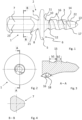
Fig. 1 ist eine Seitenansicht einer ersten Ausführungsform einer Schraube, welche insbesondere für die orale Chirurgie, und zwar insbesondere zum Befestigen von Flächengebilden, wie Kollagenmembranen oder Magnesiumfolien, vorgesehen ist. -
Fig. 2 ist eine Draufsicht auf die Spitze der Schraube. -
Fig. 3 ist eine Schnittansicht entlang A-A gemäßFig. 2 . -
Fig. 4 ist eine Schnittansicht entlang B-B derFig. 1 . -
Fig. 5 ist eine Seitenansicht eines anderen Ausführungsbeispiels einer Schraube. Diese ist länger ausgebildet und insbesondere zur Befestigung von Blöcken, mit denen Knochendefekte aufgefüllt werden, vorgesehen. -
Fig. 6 ist eine vergrößerte Ansicht derFig. 5 . -
Fig. 7 zeigt, schematisch dargestellt, wie ein Implantat mit einer der Schrauben befestigt werden kann. -
Fig. 8 und Fig. 9 zeigen eine einschlagbare Ausführungsform einer Schraube. -
Fig. 10 und Fig. 11 zeigen ein mit einem Dentalbohrer oder Handschraubendreher koppelbares Zwischenstück für eine der Schrauben. -
Fig. 1 ist eine Seitenansicht einer Schraube 1 gemäß eines ersten Ausführungsbeispiels der Erfindung. - Die Schrauben haben generell vorzugsweise eine Gesamtlänge (einschließlich Kopf 2 mit Antrieb 7) von 3 bis 20 mm. Die hier gegenüber
Fig. 5 und Fig. 6 dargestellte kürzere Version hat vorzugsweise eine Gesamtlänge von 5 bis 10 mm. - Die Schraube 1 umfasst einen Kopf 2, welcher aus der Kappe 5 und dem Antrieb 7 besteht. An den Kopf 2 grenzt ein Schaft 4, der in diesem Ausführungsbeispiel unmittelbar in das Gewinde 3 übergeht.
- Die Kappe 5 ist plattenförmig ausgestaltet und in diesem Ausführungsbeispiel an der Oberseite 9 abgerundet.
- Die Unterseite bildet eine vorzugsweise ebene Anlagefläche 6, die bei bestimmungsgemäßer Verwendung das Implantat sichert.
- An die Kappe 9 grenzt der Antrieb 7 an.
- Mit dem Antrieb 7 kann die Schraube 1 in ein Handhabungswerkzeug (nicht dargestellt) eingesetzt werden. Der Antrieb 7 wird dabei vorzugsweise von dem Handhabungswerkzeug so gesichert, dass er nicht herausfallen kann.
- Zwischen der Oberseite 9 der Kappe 5 und dem Antrieb 7 befindet sich eine Einschnürung, welche eine Sollbruchstelle 8 bildet.
- Im Bereich der Sollbruchstelle 8 ist der Durchmesser der Schraube 1 am kleinsten.
- Insbesondere kann die Sollbruchstelle 8 einen 5 bis 10 % kleineren Durchmesser als die dünnste Stelle des Schaftes 4 oder des Kerndurchmessers des Gewindes 3 aufweisen.
- Die Sollbruchstelle 8 befindet sich direkt angrenzend zur Kappe 5, so dass beim Abbrechen des Antriebs 7 nur noch die dann flache Kappe 5 verbleibt.
- Von der Sollbruchstelle 8, welche insbesondere als Radius ausgebildet sein kann, vergrößert sich in Richtung Antrieb 7 der Durchmesser der Schraube 1, in diesem Ausführungsbeispiel in Form eines Kegelstumpfes in dem Bereich 21 mit einem Spitzenwinkel von beispielsweise 40 bis 80°.
- Das Gewinde 3 ist einzügig ausgebildet. Der Gewindezug 16 läuft vorzugsweise weniger als 10, besonders bevorzugt weniger als 6 Mal um den Kern. So kann die Schraube 1 mit weinigen Umdrehungen eingedreht werden.
- Die Spitze 17 der Schraube 1 ist zum einen selbstschneidend ausgebildet und mit der Schneide 14 versehen. Über die Schneide 14 werden beim Eindrehen der Schraube 1 in ein vorgebohrtes Bohrloch die Gewindezüge in den Knochen eingebracht.
- Weiter hat die Spitze 17 einen Zentrierkegel 13, welcher in diesem Ausführungsbeispiel eine Mantellinie hat, die einen steileren Winkel zur Mittelachse 23 der Schraube 1 einnimmt als die Schneidkante 22 der Schneide 14.
- Die Schneidkante 22 kann insbesondere einen Winkel zur Mittelachse 23 von 10 bis 30° einnehmen.
- Das Gewinde 3 erstreckt sich bei diesem Ausführungsbeispiel nahezu bis zum Kopf 2 der Schraube 1. Der konusförmige Abschnitt 10 des Schaftes 4 grenzt bei diesem Ausführungsbeispiel einer Schraube 1 direkt an das Gewinde 3 an.
- Angrenzend zur Unterseite, also der Anlagefläche 6 der Kappe 5, vergrößert sich der Durchmesser des Schaftes 4 vom Gewinde 3 ausgehend in Richtung der Kappe 5.
- Es ist in diesem Ausführungsbeispiel ein konusförmiger Abschnitt 10 vorgesehen, welcher vorzugsweise zur Mittelachse 23 eine Mantellinie mit einem Winkel von 20 bis 40° hat.
- Im Bereich des konusförmigen Abschnitts 10 vergrößert sich der Durchmesser des Schaftes 4 vorzugsweise auf das 1,2 bis 1,7fache des kleinsten Durchmessers des Schaftes 4 und/oder des Kerndurchmessers des Gewindes 3.
- Der Übergangsbereich 11 vom konusförmigen Abschnitt 10 des Schaftes zum Kopf 2 hin ist in diesem Ausführungsbeispiel als Radius ausgebildet.
- In dem Übergangsbereich 11, welcher insbesondere einen Radius von 0,1 bis 0,5 mm haben kann, vergrößert sich der Durchmesser sprunghaft, so dass die Schraube 1 beim Eindrehen spätestens durch diesen Übergangsbereich 11 gestoppt wird.
- Der gewindeseitige Übergangsbereich 12 des konusförmigen Abschnitts 10 ist vorzugsweise abgerundet ausgebildet.
- Es wird so insbesondere bei der Befestigung von biegsamen Flächengebilden wie Kollagenmembranen oder Folien verhindert, dass die Anlagefläche 6 derart auf das Implantat gepresst wird, dass es zu einer Ausstanzung kommt.
- Der Durchmesser der Kappe 5 beträgt vorzugsweise 2 bis 4 mm, der Durchmesser des Schaftes beträgt vorzugsweise 0,6 bis 1,5 mm.
- Der Zentrierkegel 13 kann einen Spitzenwinkel von 70 bis 110° aufweisen.
- Das Gewinde der erfindungsgemäßen Knochenschraube hat vorzugsweise eine Länge von 2 bis 18 mm, bei dieser Ausführungsform einer kurzen Schraube vorzugsweise von 2 bis 5 mm.
- Vorzugsweise läuft der Gewindezug 16 weniger als fünf, besonders bevorzugt weniger als vier Mal um die Schraube 1. So kann die Schraube mit nur wenigen Umdrehungen eingedreht werden.
-
Fig. 2 zeigt eine Draufsicht auf die Spitze der Schraube 1. -
Fig. 3 ist eine Detailansicht eines Schnittes entlang der Linie A-A derFig. 2 . - Hier ist zu erkennen, dass die Gewindezüge 16 als abgerundete Einsenkungen ausgebildet sind, deren Flanken 18 vorzugsweise in einen Flankenwinkel α von 90 bis 150° einnehmen. Die Gewindezähne 15 sind vorzugsweise flach ausgebildet, insbesondere haben diese eine axiale Länge von 0,2 bis 0,5 mm.
- Das Gewinde 3 ist in diesem Ausführungsbeispiel als einzügiges Trapezgewinde mit abgerundetem Zahngrund ausgebildet.
- Die Breite b1 eines Gewindezahns 15 kann mindestens das 0,5fach der Breite b2 des Zahngrundes (einschließlich Zahnflanken) betragen.
- Die Gewindezähne 15 bilden keine Spitze, da eine Spitze initial einer hohen Korrosion ausgesetzt wäre und so die Festigkeit der Schaubverbindung zu schnell nachlassen würde.
-
Fig. 4 ist eine Schnittansicht entlang der Linie B-B derFig. 1 . - Der Antrieb 7 ist bei diesem Ausführungsbeispiel im Querschnitt dreieckig mit abgerundeten Spitzen ausgebildet. Es versteht sich aber, dass die Geometrie des Antriebs 7 recht beliebig ist. Diese muss nur die Übertragung eines ausreichenden Drehmoments sicherstellen. So ist beispielsweise auch eine sechskant- oder eine sternförmige Ausgestaltung denkbar (nicht dargestellt).
-
Fig. 5 ist eine Seitenansicht einer alternativen Ausführungsform einer Schraube, welche länger ist als die inFig. 1 bis Fig. 4 dargestellte Schraube. Diese hat eine Gesamtlänge von vorzugsweise mehr als 8, besonders bevorzugt mehr als 12 mm. - Die Schraube 1 umfasst auch in diesem Ausführungsbeispiel einen Kopf 2, welcher den Antrieb 7 und die flache Kappe 5 umfasst.
- Der nicht mit einem Gewinde versehene Schaft 4 der Schraube 1 ist in diesem Ausführungsbeispiel mindestens doppelt, vorzugsweise mindestens dreimal so lang wie das Gewinde 3. Schaft 4 und Gewinde 3 sind vorzugsweise zusammen zwischen 8 und 18 mm lang.
- Ansonsten ist die Schraube ähnlich der bezugnehmend auf
Fig. 1 bis Fig. 4 dargestellten Schraube ausgebildet und umfasst insbesondere auch den konusförmigen Abschnitt 10 am kopfseitigen Ende des Schaftes 4 sowie die Spitze 17 mit einer Schneide 14. -
Fig. 6 ist eine Detailansicht derFig. 5 , in welcher zu erkennen ist, dass die hier dargestellte lange Version einer Schraube 1 von der Ausgestaltung im Wesentlichen der kürzeren Version entsprechend der ZeichnungenFig. 1 bis Fig. 4 entspricht. - Der Schaft 4 der Schraube 1 sowie der Kerndurchmesser des Gewindes 3 ist aber vorzugsweise etwas dicker. Insbesondere hat dieser einen Durchmesser von 1,0 bis 1,3 mm.
- Es hat sich herausgestellt, dass bereits eine Einschnürung mit nur geringfügig kleinerem Durchmesser als der Schaft 4, insbesondere mit 0,01 bis 0,05 mm kleinerem Durchmesser, zu einer hinreichend sicheren Sollbruchstelle 8 führt.
- Auch die Spitze 17 ist entsprechend der
Fig. 1 ausgebildet und umfasst eine Schneide 14 zum Einbringen der Gewindezüge sowie einen Zentrierkegel 13 ohne Schneide. -
Fig. 7 ist eine schematische Ansicht eines als Flächengebilde, beispielsweise als Kollagenfolie ausgebildeten Implantats 19. Dieses wird zum Abdecken beispielsweise eines Knochendefekts auf die Wunde gelegt. Sodann werden mittels eines Bohrers Bohrlöcher 20 eingebracht, welche im Wesentlichen dem Durchmesser des Schaftes der Schraube und/oder dem Durchmesser des Gewindekerns entsprechen. - Anschließend wird das Implantat 19 mit zumindest einer Schraube befestigt.
- Dabei wird die Schraube in das Bohrloch 20 hineingedreht, bis am Ende des konusförmigen Abschnitts (10 in
Fig. 1 undFig. 6 ) die Drehung gestoppt wird. - Der Antrieb bricht sodann entweder durch das Drehmoment beim Eindrehen ab, wenn der Kopf der Schraube mit dem Implantat bzw. dem Knochen in Kontakt kommt. Der Benutzer kann den Antrieb aber auch durch Abknicken abbrechen.
- Die Schrauben bestehen vorzugsweise aus einer Magnesiumlegierung. Im Falle der Verwendung einer Magnesiumfolie als Implantat 19 kommt es aufgrund der allenfalls geringen Spannungsdifferenz nicht zu einer erhöhten Korrosion, so dass sowohl Implantat 19 als auch Schraube erst nach Heilung degradieren.
-
Fig. 8 und Fig. 9 zeigt eine alternative Ausführungsform einer Schraube 1, welche auch eingeschlagen werden kann. - Wie in
Fig. 8 dargestellt, verläuft die selbstschneidende Spitze 17 bis zum vorderen Ende der Schraube 1. Die selbstschneidende Spitze 17 hat einen Kegelwinkel von unter 45°, vorzugsweise von unter 40°. Ein separater Zentrierkegel mit einem anderen Kegelwinkel (13 inFig. 1 ) ist nicht vorgesehen. - Weiter ist das Gewinde 8 mehrzügig, insbesondere zweizügig, ausgebildet und hat eine höhere Steigung als das Gewinde der Ausführungsformen gemäß
Fig. 1 bis Fig. 6 . -
Fig. 9 ist eine Schnittansicht entlang der Linie B-B ausFig. 8 . Der Antrieb 7 hat eine andere Geometrie als der Antrieb gemäßFig. 1 bis Fig. 6 , nämlich die eines auf einer Seite angeschnittenen Kreiszylinders. Es versteht sich aber, dass der Antrieb ebenso die dieFig. 4 dargestellte Geometrie aufweisen kann. - Ansonsten entspricht die in
Fig. 8 und Fig. 9 dargestellte Schraube im Wesentlichen dem Ausführungsbeispiel gemäßFig. 1 . -
Fig. 10 ist eine Schnittansicht eines Zwischenstücks 24 für eine Schraube, welcher auf einen Dentalbohrer oder Handschraubendreher (nicht dargestellt) aufgesetzt werden kann. - Das Zwischenstück 24 umfasst hierzu eine mit dem Dentalbohrer oder Handschraubendreher verbindbare Kupplung 26, die, abgestimmt auf den verwendeten Bohrer oder Schraubendreher, beliebig ausgebildet sein kann.
- Weiter umfasst das Zwischenstück, insbesondere ähnlich wie ein Bit-Halter, eine auf Aufnahme 25 für den Antrieb einer Schraube.
- Wie in der Draufsicht auf die Stirnseite gemäß
Fig. 11 zu erkennen ist, ist die Geometrie der Aufnahme 25 in diesem Ausführungsbeispiel auf die inFig. 4 dargestellte Geometrie des Antriebs der Schraube abgestimmt. - Vorzugsweise kann der Antrieb der Schraube in der Aufnahme 25 verklemmt oder verrastet werden. Nach vollständigem Eindrehen der Schraube verbleibt der abgebrochene Antrieb in der Aufnahme 25.
- Gemäß einer Ausführungsform (nicht dargestellt) kann der Antrieb sodann über ein Handhabungsorgan ausgeworfen werden, z.B. über einen in dem Zwischenstück 24 axial verschiebbaren Stift, der den Antrieb herausdrückt oder durch Freigabe einer Verrastung.
- Durch die Erfindung wurde eine einfache und zuverlässige Befestigung, insbesondere von Dentalimplantaten, bereitgestellt.
-
- 1
- Schraube
- 2
- Kopf
- 3
- Gewinde
- 4
- Schaft
- 5
- Kappe
- 6
- Anlagefläche
- 7
- Antrieb
- 8
- Sollbruchstelle
- 9
- Oberseite
- 10
- konusförmiger Abschnitt
- 11
- Übergangsbereich
- 12
- Übergangsbereich
- 13
- Zentrierkegel
- 14
- Schneide
- 15
- Gewindezahn
- 16
- Gewindezug
- 17
- Spitze
- 18
- Flanke
- 19
- Implantat
- 20
- Bohrung
- 21
- Bereich
- 22
- Schneidkante
- 23
- Mittelachse
- 24
- Zwischenstück
- 25
- Aufnahme
- 26
- Kupplung
Claims (13)
- Schraube (1) zur Fixierung eines Implantats (19), wobei die Schraube (1) aus
einem bioresorbierbaren Material, nämlich aus Magnesium oder aus einer Magnesiumlegierung besteht, wobei die Schraube (1) ein Gewinde (3) zum Eindrehen in den Knochen aufweist, wobei die Schraube (1) einen Kopf (2) mit einer Kappe (5) und einem Antrieb (7) umfasst, wobei die Kappe (5) eine im wesentlichen flache Anlagefläche für das Implantat (19) aufweist, wobei zwischen dem Antrieb (7) und der Kappe (5) eine Sollbruchstelle (8) vorhanden ist, welche als Einschnürung zwischen einer Oberseite der Kappe (5) und dem Antrieb (7) ausgebildet ist, wobei sich ein Schaft (4) der Schraube (1) zur Kappe (5) hin verdickt, wobei das Gewinde (3) derart ausgebildet ist, dass die Zähne des Gewindes (3) außen flach oder abgerundet ausgebildet sind und der Zahngrund des Gewindes (3) abgerundet in die Zahnflanken (18) übergeht, und wobei die Schraube (1) eine selbstschneidende Spitze (17) hat. - Schraube (1) nach dem vorstehenden Anspruch, dadurch gekennzeichnet, dass die Sollbruchstelle (8) als Einschnürung ausgebildet ist.
- Schraube (1)nach einem der vorstehenden Ansprüche, dadurch gekennzeichnet, dass die Kappe (5) plattenförmig ausgebildet ist, vorzugsweise dass die Kappe (5) eine maximale Höhe bis zur Sollbruchstelle (8) von weniger als 2 mm, bevorzugt von weniger als 1 mm und besonders bevorzugt von weniger als 0,8 mm aufweist.
- Schraube (1) nach einem der vorstehenden Ansprüche, dadurch gekennzeichnet, dass der kleinste Durchmesser des Schaftes (4) maximal so groß ist wie der Kerndurchmesser des Gewindes (3), insbesondere dass der kleinste Durchmesser des Schaftes (4) dem Kerndurchmesser des Gewindes (3) entspricht.
- Schraube (1) nach einem der vorstehenden Ansprüche, dadurch gekennzeichnet, dass die Kappe (5) einen Durchmesser von 1 bis 6 mm, vorzugsweise von 2 bis 4 mm hatund/oder dass die Kappe (5) den 1,5 bis 5fachen, vorzugsweise den 2 bis 4fachen Durchmesser des Schaftes (4)und/oder Kerns des Gewindes (3) hatund/oder dass die Steigung des Gewindes (3) 0,5 bis 1,6 mm beträgtund/oder dass die Schraube (1) eine Zentrierspitze aufweist.
- Schraube (1)nach einem der vorstehenden Ansprüche, dadurch gekennzeichnet, dass die Schraube (1) aus einer Magnesiumlegierung besteht, insbesondere einer Magnesiumlegierung mit Yttrium, Zink, Mangan und/oder Calcium.
- Schraube (1) nach einem der vorstehenden Ansprüche, dadurch gekennzeichnet, dass die Schraube (1) eine Beschichtung aufweist, insbesondere eine Beschichtung aus Magnesiumfluorid.
- Schraube (1) nach einem der vorstehenden Ansprüche, dadurch gekennzeichnet, dass der Schaft (4)angrenzend zum Kopf (2) einen konusförmigen, insbesondere kegelstumpfförmigen, Abschnitt aufweist.
- Schraube (1)nach dem vorstehenden Anspruch, dadurch gekennzeichnet, dass der Winkel des konusförmigen Abschnitt in einem Übergangsbereich zur Kappe (5)hin bezogen auf eine Mittelachse steiler wird, insbesondere dass der Übergangsbereich (11) als Radius ausgebildet ist.
- Schraube (1) nach dem vorstehenden Anspruch, dadurch gekennzeichnet, dass der Übergangsbereich (11) eine Länge von 0,5 bis 2 mm hat.
- Schraube (1) nach einem der vorstehenden Ansprüche, dadurch gekennzeichnet, dass die Schraube (1) unterhalb der Kappe (5)einen konusförmigen Abschnitt aufweist, welcher einen Winkel bezogen auf die Mittelachse der Schraube (1) von 20 bis 40°, vorzugsweise von 35 bis 45° einnimmt und/oder welcher eine Länge von 0,2 bis 10 mm, vorzugsweise von 0,4 bis 0,6 mm, hat.
- Set mit zumindest einer Schraube (1) nach einem der vorstehenden Ansprüche und einem Implantat (19), welches als Flächengebilde ausgebildet ist.
- Set nach dem vorstehenden Anspruch, weiter umfassend einen Vorbohrer, welcher vorzugsweise in etwa den Durchmesser des Schafts (4) der Schraube (1) aufweist, und/oder ein Zwischenstück zur Aufnahme einer Schraube (1), wobei das Zwischenstück eine Kupplung (26)zur Verbindung mit einem Handstück oder mit einem Dentalbohrer aufweist, und/oder einen Halter für eine Mehrzahl von Schrauben.
Applications Claiming Priority (2)
| Application Number | Priority Date | Filing Date | Title |
|---|---|---|---|
| DE102017119657.9A DE102017119657B4 (de) | 2017-08-28 | 2017-08-28 | Dentalschraube |
| PCT/EP2018/073094 WO2019042974A2 (de) | 2017-08-28 | 2018-08-28 | Dentalschraube |
Publications (2)
| Publication Number | Publication Date |
|---|---|
| EP3675769A2 EP3675769A2 (de) | 2020-07-08 |
| EP3675769B1 true EP3675769B1 (de) | 2023-04-26 |
Family
ID=63642936
Family Applications (1)
| Application Number | Title | Priority Date | Filing Date |
|---|---|---|---|
| EP18773079.1A Active EP3675769B1 (de) | 2017-08-28 | 2018-08-28 | Dentalschraube |
Country Status (10)
| Country | Link |
|---|---|
| US (1) | US11291548B2 (de) |
| EP (1) | EP3675769B1 (de) |
| JP (1) | JP7305619B2 (de) |
| KR (1) | KR102625759B1 (de) |
| CN (1) | CN111050692A (de) |
| BR (1) | BR112020003858B1 (de) |
| DE (1) | DE102017119657B4 (de) |
| ES (1) | ES2946273T3 (de) |
| FI (1) | FI3675769T3 (de) |
| WO (1) | WO2019042974A2 (de) |
Families Citing this family (26)
| Publication number | Priority date | Publication date | Assignee | Title |
|---|---|---|---|---|
| US11806250B2 (en) | 2018-02-22 | 2023-11-07 | Warsaw Orthopedic, Inc. | Expandable spinal implant system and method of using same |
| US12622692B2 (en) | 2020-05-14 | 2026-05-12 | Inovedis Gmbh | Tendon fixation plate |
| CN116234503B (zh) * | 2020-05-14 | 2024-06-28 | 伊诺维迪斯公司 | 肌腱固定板 |
| US12239544B2 (en) | 2020-11-05 | 2025-03-04 | Warsaw Orthopedic, Inc. | Rhomboid shaped implants |
| US11564724B2 (en) | 2020-11-05 | 2023-01-31 | Warsaw Orthopedic, Inc. | Expandable inter-body device, system and method |
| US11963881B2 (en) | 2020-11-05 | 2024-04-23 | Warsaw Orthopedic, Inc. | Expandable inter-body device, system, and method |
| US12318308B2 (en) | 2020-11-05 | 2025-06-03 | Warsaw Orthopedic, Inc. | Dual expandable inter-body device |
| US11376134B1 (en) | 2020-11-05 | 2022-07-05 | Warsaw Orthopedic, Inc. | Dual expanding spinal implant, system, and method of use |
| US11517443B2 (en) | 2020-11-05 | 2022-12-06 | Warsaw Orthopedic, Inc. | Dual wedge expandable implant, system and method of use |
| US12121453B2 (en) | 2020-11-05 | 2024-10-22 | Warsaw Orthopedic, Inc. | Dual wedge expandable implant with eyelets, system, and method of use |
| US11395743B1 (en) | 2021-05-04 | 2022-07-26 | Warsaw Orthopedic, Inc. | Externally driven expandable interbody and related methods |
| US11833059B2 (en) | 2020-11-05 | 2023-12-05 | Warsaw Orthopedic, Inc. | Expandable inter-body device, expandable plate system, and associated methods |
| US11638653B2 (en) | 2020-11-05 | 2023-05-02 | Warsaw Orthopedic, Inc. | Surgery instruments with a movable handle |
| US12171439B2 (en) | 2020-11-05 | 2024-12-24 | Warsaw Orthopedic, Inc. | Protected drill |
| US11612499B2 (en) | 2021-06-24 | 2023-03-28 | Warsaw Orthopedic, Inc. | Expandable interbody implant |
| US12485019B2 (en) | 2021-06-24 | 2025-12-02 | Warsaw Orthopedic, Inc. | Parallel jaw inserter |
| US12295865B2 (en) | 2021-06-24 | 2025-05-13 | Warsaw Orthopedic, Inc. | Expandable interbody implant and corresponding inserter |
| US12268614B2 (en) | 2021-06-24 | 2025-04-08 | Warsaw Orthopedic, Inc. | Interbody implant with adjusting shims |
| US12440349B2 (en) | 2021-11-01 | 2025-10-14 | Warsaw Orthopedic, Inc. | Expandable interbody implant and breakoff screw |
| WO2022271280A1 (en) | 2021-06-24 | 2022-12-29 | Warsaw Orthopedic, Inc. | Expandable interbody implant and corresponding surgical tool |
| WO2023003808A1 (en) * | 2021-07-20 | 2023-01-26 | University Of Pittsburgh - Of The Commonwealth System Of Higher Education | Magnesium mesh with features designed to bioabsorb progressively to improve dental bone regeneration |
| CN113730000A (zh) * | 2021-09-29 | 2021-12-03 | 北京大学口腔医学院 | 一种锌基合金可降解牵张成骨器 |
| US11850163B2 (en) | 2022-02-01 | 2023-12-26 | Warsaw Orthopedic, Inc. | Interbody implant with adjusting shims |
| US20230372067A1 (en) * | 2022-05-20 | 2023-11-23 | Dustin Shin | Dental implant for preserving bone and improving osseointegration |
| WO2024237814A1 (ru) * | 2023-05-12 | 2024-11-21 | Елизавета Михайловна ЧЕРНОВОЛ | Винтовой эндостальный имплантат и способ его изготовления |
| US12533241B2 (en) | 2023-05-16 | 2026-01-27 | Warsaw Orthopedic, Inc. | Distracting and angling expandable interbody device |
Citations (2)
| Publication number | Priority date | Publication date | Assignee | Title |
|---|---|---|---|---|
| DE69528501T2 (de) * | 1994-07-04 | 2003-07-10 | Depuy France, Villeurbanne | Osteosynthetische Stiftvorrichtung |
| US6723099B1 (en) * | 2001-11-08 | 2004-04-20 | Biomet, Inc. | Three sided tack for bone fixation |
Family Cites Families (40)
| Publication number | Priority date | Publication date | Assignee | Title |
|---|---|---|---|---|
| DE3630863A1 (de) | 1986-09-08 | 1988-03-17 | Mecron Med Prod Gmbh | Knochenschraube |
| DE3701765C1 (de) | 1987-01-22 | 1988-06-09 | Ethicon Gmbh | Knochenschraube |
| FR2625430A1 (fr) * | 1987-12-30 | 1989-07-07 | Guinounet Alain | Vis de blocage d'une plaque d'osteosynthese et procede de fabrication d'une telle vis |
| CA2063159C (en) * | 1991-03-22 | 1999-06-15 | Thomas W. Sander | Orthopedic fastener |
| CA2158443C (en) * | 1993-03-16 | 2003-11-25 | Stephen E. Hughes | Method for preparation and transplantation of volute grafts and surgical instrument therefor |
| DE19601477C2 (de) * | 1996-01-17 | 1999-12-16 | Axel Kirsch | Befestigungsnagel |
| US6117162A (en) * | 1996-08-05 | 2000-09-12 | Arthrex, Inc. | Corkscrew suture anchor |
| US5876435A (en) * | 1996-08-20 | 1999-03-02 | Porex Surgical Inc. | Coupling for porous resin orbital implant and ocular prosthesis |
| FR2770126B1 (fr) * | 1997-10-28 | 2000-02-18 | Groupe Grion Soc Civ | Vis chirurgicale pour le repositionnement de la tuberosite tibiale |
| US5971987A (en) | 1998-09-18 | 1999-10-26 | Ethicon, Inc. | Biocompatible absorbable polymer fastener and driver for use in surgical procedures |
| US6096060A (en) * | 1999-05-20 | 2000-08-01 | Linvatec Corporation | Bioabsorbable threaded soft tissue anchor system |
| EP1267733A4 (de) * | 2000-02-03 | 2005-06-01 | Alphatec Mfg Inc | Intramodulare vebindungsschraube |
| DE10065799C1 (de) * | 2000-12-30 | 2002-04-25 | Rehau Ag & Co | Schädelschraube |
| US20080140118A1 (en) * | 2001-09-13 | 2008-06-12 | United States Surgical Corporation | Knotless tissue anchor |
| US7077864B2 (en) * | 2002-02-12 | 2006-07-18 | Cross Medical Products, Inc. | Vertebral interbody cage with translatable locking screw |
| EP1485626B1 (de) * | 2002-02-26 | 2007-06-06 | Degima Medizinprodukte GmbH | Gewindevorrichtung mit verbessertem widerstand gegen durch torsion verursachtes brechen |
| US7670142B2 (en) * | 2003-06-03 | 2010-03-02 | Intra-Lock International, Inc. | Prosthesis mounting device and assembly |
| CA2527778C (en) * | 2003-06-13 | 2011-11-08 | Tyco Healthcare Group Lp | Multiple member interconnect for surgical instrument and absorbable screw fastener |
| CN1565389A (zh) * | 2003-06-13 | 2005-01-19 | 比阿特丽斯·阿尔达马博伦布鲁 | 牙科植入物 |
| US20060058796A1 (en) * | 2004-09-14 | 2006-03-16 | Hartdegen Vernon R | Compression brace |
| US8535357B2 (en) * | 2004-12-09 | 2013-09-17 | Biomet Sports Medicine, Llc | Continuous phase compositions for ACL repair |
| DE202006006920U1 (de) | 2006-04-25 | 2007-08-30 | Biomed Est. | Dentalimplantat |
| US20070218750A1 (en) * | 2006-03-17 | 2007-09-20 | Nexa Orthopedics, Inc. | Snap-off screw with recessed breakoff area |
| US20070270859A1 (en) | 2006-04-28 | 2007-11-22 | Sdgi Holdings, Inc. | Orthopedic screw with break away drive |
| KR20100021529A (ko) * | 2007-06-20 | 2010-02-24 | 유니스틸 테크놀로지 인터내셔널 리미티드 | 스레드 형성 스크류 스레드 및 대응하는 스레드 롤 다이 |
| DE102008037200B4 (de) * | 2008-08-11 | 2015-07-09 | Aap Implantate Ag | Verwendung eines Druckgussverfahrens zur Herstellung eines Implantats aus Magnesium sowie Magnesiumlegierung |
| CN101732098B (zh) * | 2009-11-10 | 2012-02-01 | 四川大学 | 一种抗微动损伤的骨内牙种植体 |
| CN105877829B (zh) * | 2010-06-07 | 2018-06-22 | 卡波菲克斯整形有限公司 | 复合材料骨植入物 |
| DE102010055433B4 (de) | 2010-12-10 | 2014-07-24 | Celgen Ag | Knochenschraube und Vorrichtung zur Knochendistraktion |
| US20120214127A1 (en) | 2011-02-22 | 2012-08-23 | Warsaw Orthopedic, Inc. | Dental implant system with separable drive and method |
| CN202477833U (zh) * | 2011-12-28 | 2012-10-10 | 广州莱德尔生物科技有限公司 | 一种可降解镁合金矫形内固定拉力螺丝钉 |
| KR102069592B1 (ko) * | 2012-01-31 | 2020-01-23 | 더유니버시티오브톨레도 | 생체 활성 융합 장치 |
| JP2015536176A (ja) * | 2012-11-15 | 2015-12-21 | 何 志忠HO, Chih−Chung | 第一メネジ及び第二メネジを有する歯科インプラント |
| JP2014136008A (ja) | 2013-01-16 | 2014-07-28 | Olympus Corp | インプラント |
| WO2014169058A1 (en) * | 2013-04-09 | 2014-10-16 | Smith & Nephew, Inc | Open-architecture interference screw |
| DE102014008449A1 (de) * | 2014-06-04 | 2015-12-31 | Celgen Ag | Distraktionsmembran auf Magnesiumbasis |
| CN203988332U (zh) * | 2014-08-21 | 2014-12-10 | 赵德伟 | 一种前置螺纹可降解纯镁螺钉 |
| DE102015009932A1 (de) | 2015-07-28 | 2017-02-02 | Celgen Ag | Implantat mit Distraktionsmembran zur Kallusdistraktion |
| KR101822255B1 (ko) * | 2016-02-15 | 2018-01-26 | 서울대학교산학협력단 | 생체적합성 불소계 세라믹 코팅층을 포함하는 금속 임플란트의 제조방법 |
| CN106730043B (zh) * | 2016-12-19 | 2022-09-20 | 苏州西脉新诚生物科技有限公司 | 一种高强度可吸收骨折内固定骨螺钉 |
-
2017
- 2017-08-28 DE DE102017119657.9A patent/DE102017119657B4/de active Active
-
2018
- 2018-08-28 BR BR112020003858-0A patent/BR112020003858B1/pt active IP Right Grant
- 2018-08-28 FI FIEP18773079.1T patent/FI3675769T3/en active
- 2018-08-28 EP EP18773079.1A patent/EP3675769B1/de active Active
- 2018-08-28 KR KR1020207007697A patent/KR102625759B1/ko active Active
- 2018-08-28 ES ES18773079T patent/ES2946273T3/es active Active
- 2018-08-28 US US16/642,109 patent/US11291548B2/en active Active
- 2018-08-28 WO PCT/EP2018/073094 patent/WO2019042974A2/de not_active Ceased
- 2018-08-28 JP JP2020512596A patent/JP7305619B2/ja active Active
- 2018-08-28 CN CN201880055904.0A patent/CN111050692A/zh active Pending
Patent Citations (2)
| Publication number | Priority date | Publication date | Assignee | Title |
|---|---|---|---|---|
| DE69528501T2 (de) * | 1994-07-04 | 2003-07-10 | Depuy France, Villeurbanne | Osteosynthetische Stiftvorrichtung |
| US6723099B1 (en) * | 2001-11-08 | 2004-04-20 | Biomet, Inc. | Three sided tack for bone fixation |
Also Published As
| Publication number | Publication date |
|---|---|
| CN111050692A (zh) | 2020-04-21 |
| DE102017119657A1 (de) | 2019-02-28 |
| RU2020111387A (ru) | 2021-10-04 |
| JP7305619B2 (ja) | 2023-07-10 |
| WO2019042974A2 (de) | 2019-03-07 |
| US20200179120A1 (en) | 2020-06-11 |
| KR102625759B1 (ko) | 2024-01-17 |
| EP3675769A2 (de) | 2020-07-08 |
| US11291548B2 (en) | 2022-04-05 |
| ES2946273T3 (es) | 2023-07-14 |
| JP2020531209A (ja) | 2020-11-05 |
| KR20200049787A (ko) | 2020-05-08 |
| WO2019042974A3 (de) | 2019-06-06 |
| BR112020003858B1 (pt) | 2022-12-20 |
| DE102017119657B4 (de) | 2019-03-14 |
| FI3675769T3 (en) | 2023-06-20 |
| BR112020003858A2 (pt) | 2020-09-08 |
Similar Documents
| Publication | Publication Date | Title |
|---|---|---|
| DE102017119657B4 (de) | Dentalschraube | |
| EP1096892B1 (de) | Knochenschraube, insbesondere für den einsatz bei translaminärer wirbelverschraubung | |
| EP0317688B1 (de) | Kieferimplantat | |
| EP2440147B1 (de) | Chirurgieinstrument mit knochenschraube | |
| EP0513943B1 (de) | Implantat mit Pressfläche | |
| DE69011373T2 (de) | Absorbierbare chirurgische Klammer mit knochendurchdringenden Elementen. | |
| DE3789973T2 (de) | Zahnimplantat zur Befestigung von Zahnersatz-Suprakonstruktionen. | |
| EP0967926A1 (de) | Implantat für die osteosynthese | |
| DE3027138A1 (de) | Einrichtung mit einem implantat und zu dessen befestigung an einem knochen dienenden schrauben und einrichtung zum verbinden zweier durch einen zwischenraum getrennter knochenstuecke | |
| DE4339804A1 (de) | Kraftübertragungsglied für Osteosynthesearbeiten | |
| DE102009032034A1 (de) | Chirurgische Knochenverankerungsvorrichtung und Wirbelsäulenfixationssystem | |
| EP1626670A2 (de) | Zahnimplantat mit grundkörper und implantatpfosten sowie grundkörper und implantatpfosten für ein zahnimplantat | |
| DE102010042930A1 (de) | Osteosynthesevorrichtung | |
| EP3542750A1 (de) | Dentalimplantatsystem | |
| DE29716883U1 (de) | Kieferimplantat und Suprastruktur für zahnmedizinische Zwecke zur Halterung eines Zahnersatzes am menschlichen Kiefer | |
| DE102005014546B4 (de) | Großfragmentplatte und Adapter für eine Großfragmentplatte | |
| EP3995102B1 (de) | Knochenaufbau-schraube sowie system zur modifikation eines menschlichen oder tierischen knochens | |
| EP1915969A1 (de) | Dentalimplantat zur Abstützung einer Dentalprothese | |
| DE202010015755U1 (de) | Dentalimplantatsystem | |
| EP0047436A1 (de) | Verankerungsvorrichtung für die Befestigung von Zähnen oder Zahnprothesen | |
| CH707433A2 (de) | Zahnimplantat, Support mit einem Zahnimplantat und Einrichtung zur Bildung eines Lochs in einem Knochen. | |
| DE102006007541A1 (de) | Implantat für Zahnersatzbefestigung | |
| RU2782108C2 (ru) | Биорезорбируемый винт | |
| EP1563802A2 (de) | Wurzelförmiges Kieferimplantat | |
| DE68903568T2 (de) | Implantat. |
Legal Events
| Date | Code | Title | Description |
|---|---|---|---|
| STAA | Information on the status of an ep patent application or granted ep patent |
Free format text: STATUS: UNKNOWN |
|
| STAA | Information on the status of an ep patent application or granted ep patent |
Free format text: STATUS: THE INTERNATIONAL PUBLICATION HAS BEEN MADE |
|
| PUAI | Public reference made under article 153(3) epc to a published international application that has entered the european phase |
Free format text: ORIGINAL CODE: 0009012 |
|
| STAA | Information on the status of an ep patent application or granted ep patent |
Free format text: STATUS: REQUEST FOR EXAMINATION WAS MADE |
|
| 17P | Request for examination filed |
Effective date: 20200221 |
|
| AK | Designated contracting states |
Kind code of ref document: A2 Designated state(s): AL AT BE BG CH CY CZ DE DK EE ES FI FR GB GR HR HU IE IS IT LI LT LU LV MC MK MT NL NO PL PT RO RS SE SI SK SM TR |
|
| AX | Request for extension of the european patent |
Extension state: BA ME |
|
| DAV | Request for validation of the european patent (deleted) | ||
| DAX | Request for extension of the european patent (deleted) | ||
| STAA | Information on the status of an ep patent application or granted ep patent |
Free format text: STATUS: EXAMINATION IS IN PROGRESS |
|
| 17Q | First examination report despatched |
Effective date: 20210607 |
|
| GRAP | Despatch of communication of intention to grant a patent |
Free format text: ORIGINAL CODE: EPIDOSNIGR1 |
|
| STAA | Information on the status of an ep patent application or granted ep patent |
Free format text: STATUS: GRANT OF PATENT IS INTENDED |
|
| GRAS | Grant fee paid |
Free format text: ORIGINAL CODE: EPIDOSNIGR3 |
|
| INTG | Intention to grant announced |
Effective date: 20230221 |
|
| GRAA | (expected) grant |
Free format text: ORIGINAL CODE: 0009210 |
|
| STAA | Information on the status of an ep patent application or granted ep patent |
Free format text: STATUS: THE PATENT HAS BEEN GRANTED |
|
| AK | Designated contracting states |
Kind code of ref document: B1 Designated state(s): AL AT BE BG CH CY CZ DE DK EE ES FI FR GB GR HR HU IE IS IT LI LT LU LV MC MK MT NL NO PL PT RO RS SE SI SK SM TR |
|
| REG | Reference to a national code |
Ref country code: GB Ref legal event code: FG4D Free format text: NOT ENGLISH |
|
| REG | Reference to a national code |
Ref country code: CH Ref legal event code: EP |
|
| REG | Reference to a national code |
Ref country code: DE Ref legal event code: R096 Ref document number: 502018012044 Country of ref document: DE |
|
| REG | Reference to a national code |
Ref country code: AT Ref legal event code: REF Ref document number: 1562299 Country of ref document: AT Kind code of ref document: T Effective date: 20230515 |
|
| REG | Reference to a national code |
Ref country code: IE Ref legal event code: FG4D Free format text: LANGUAGE OF EP DOCUMENT: GERMAN |
|
| REG | Reference to a national code |
Ref country code: FI Ref legal event code: FGE |
|
| P01 | Opt-out of the competence of the unified patent court (upc) registered |
Effective date: 20230525 |
|
| REG | Reference to a national code |
Ref country code: ES Ref legal event code: FG2A Ref document number: 2946273 Country of ref document: ES Kind code of ref document: T3 Effective date: 20230714 |
|
| REG | Reference to a national code |
Ref country code: LT Ref legal event code: MG9D |
|
| REG | Reference to a national code |
Ref country code: NL Ref legal event code: MP Effective date: 20230426 |
|
| PG25 | Lapsed in a contracting state [announced via postgrant information from national office to epo] |
Ref country code: NL Free format text: LAPSE BECAUSE OF FAILURE TO SUBMIT A TRANSLATION OF THE DESCRIPTION OR TO PAY THE FEE WITHIN THE PRESCRIBED TIME-LIMIT Effective date: 20230426 |
|
| PG25 | Lapsed in a contracting state [announced via postgrant information from national office to epo] |
Ref country code: SE Free format text: LAPSE BECAUSE OF FAILURE TO SUBMIT A TRANSLATION OF THE DESCRIPTION OR TO PAY THE FEE WITHIN THE PRESCRIBED TIME-LIMIT Effective date: 20230426 Ref country code: PT Free format text: LAPSE BECAUSE OF FAILURE TO SUBMIT A TRANSLATION OF THE DESCRIPTION OR TO PAY THE FEE WITHIN THE PRESCRIBED TIME-LIMIT Effective date: 20230828 Ref country code: NO Free format text: LAPSE BECAUSE OF FAILURE TO SUBMIT A TRANSLATION OF THE DESCRIPTION OR TO PAY THE FEE WITHIN THE PRESCRIBED TIME-LIMIT Effective date: 20230726 |
|
| PG25 | Lapsed in a contracting state [announced via postgrant information from national office to epo] |
Ref country code: RS Free format text: LAPSE BECAUSE OF FAILURE TO SUBMIT A TRANSLATION OF THE DESCRIPTION OR TO PAY THE FEE WITHIN THE PRESCRIBED TIME-LIMIT Effective date: 20230426 Ref country code: PL Free format text: LAPSE BECAUSE OF FAILURE TO SUBMIT A TRANSLATION OF THE DESCRIPTION OR TO PAY THE FEE WITHIN THE PRESCRIBED TIME-LIMIT Effective date: 20230426 Ref country code: LV Free format text: LAPSE BECAUSE OF FAILURE TO SUBMIT A TRANSLATION OF THE DESCRIPTION OR TO PAY THE FEE WITHIN THE PRESCRIBED TIME-LIMIT Effective date: 20230426 Ref country code: LT Free format text: LAPSE BECAUSE OF FAILURE TO SUBMIT A TRANSLATION OF THE DESCRIPTION OR TO PAY THE FEE WITHIN THE PRESCRIBED TIME-LIMIT Effective date: 20230426 Ref country code: IS Free format text: LAPSE BECAUSE OF FAILURE TO SUBMIT A TRANSLATION OF THE DESCRIPTION OR TO PAY THE FEE WITHIN THE PRESCRIBED TIME-LIMIT Effective date: 20230826 Ref country code: HR Free format text: LAPSE BECAUSE OF FAILURE TO SUBMIT A TRANSLATION OF THE DESCRIPTION OR TO PAY THE FEE WITHIN THE PRESCRIBED TIME-LIMIT Effective date: 20230426 Ref country code: GR Free format text: LAPSE BECAUSE OF FAILURE TO SUBMIT A TRANSLATION OF THE DESCRIPTION OR TO PAY THE FEE WITHIN THE PRESCRIBED TIME-LIMIT Effective date: 20230727 |
|
| PG25 | Lapsed in a contracting state [announced via postgrant information from national office to epo] |
Ref country code: SK Free format text: LAPSE BECAUSE OF FAILURE TO SUBMIT A TRANSLATION OF THE DESCRIPTION OR TO PAY THE FEE WITHIN THE PRESCRIBED TIME-LIMIT Effective date: 20230426 |
|
| REG | Reference to a national code |
Ref country code: DE Ref legal event code: R097 Ref document number: 502018012044 Country of ref document: DE |
|
| PG25 | Lapsed in a contracting state [announced via postgrant information from national office to epo] |
Ref country code: SM Free format text: LAPSE BECAUSE OF FAILURE TO SUBMIT A TRANSLATION OF THE DESCRIPTION OR TO PAY THE FEE WITHIN THE PRESCRIBED TIME-LIMIT Effective date: 20230426 Ref country code: SK Free format text: LAPSE BECAUSE OF FAILURE TO SUBMIT A TRANSLATION OF THE DESCRIPTION OR TO PAY THE FEE WITHIN THE PRESCRIBED TIME-LIMIT Effective date: 20230426 Ref country code: RO Free format text: LAPSE BECAUSE OF FAILURE TO SUBMIT A TRANSLATION OF THE DESCRIPTION OR TO PAY THE FEE WITHIN THE PRESCRIBED TIME-LIMIT Effective date: 20230426 Ref country code: EE Free format text: LAPSE BECAUSE OF FAILURE TO SUBMIT A TRANSLATION OF THE DESCRIPTION OR TO PAY THE FEE WITHIN THE PRESCRIBED TIME-LIMIT Effective date: 20230426 Ref country code: DK Free format text: LAPSE BECAUSE OF FAILURE TO SUBMIT A TRANSLATION OF THE DESCRIPTION OR TO PAY THE FEE WITHIN THE PRESCRIBED TIME-LIMIT Effective date: 20230426 Ref country code: CZ Free format text: LAPSE BECAUSE OF FAILURE TO SUBMIT A TRANSLATION OF THE DESCRIPTION OR TO PAY THE FEE WITHIN THE PRESCRIBED TIME-LIMIT Effective date: 20230426 |
|
| PLBE | No opposition filed within time limit |
Free format text: ORIGINAL CODE: 0009261 |
|
| STAA | Information on the status of an ep patent application or granted ep patent |
Free format text: STATUS: NO OPPOSITION FILED WITHIN TIME LIMIT |
|
| PG25 | Lapsed in a contracting state [announced via postgrant information from national office to epo] |
Ref country code: MC Free format text: LAPSE BECAUSE OF FAILURE TO SUBMIT A TRANSLATION OF THE DESCRIPTION OR TO PAY THE FEE WITHIN THE PRESCRIBED TIME-LIMIT Effective date: 20230426 |
|
| PG25 | Lapsed in a contracting state [announced via postgrant information from national office to epo] |
Ref country code: MC Free format text: LAPSE BECAUSE OF FAILURE TO SUBMIT A TRANSLATION OF THE DESCRIPTION OR TO PAY THE FEE WITHIN THE PRESCRIBED TIME-LIMIT Effective date: 20230426 |
|
| 26N | No opposition filed |
Effective date: 20240129 |
|
| PG25 | Lapsed in a contracting state [announced via postgrant information from national office to epo] |
Ref country code: LU Free format text: LAPSE BECAUSE OF NON-PAYMENT OF DUE FEES Effective date: 20230828 |
|
| PG25 | Lapsed in a contracting state [announced via postgrant information from national office to epo] |
Ref country code: LU Free format text: LAPSE BECAUSE OF NON-PAYMENT OF DUE FEES Effective date: 20230828 |
|
| PG25 | Lapsed in a contracting state [announced via postgrant information from national office to epo] |
Ref country code: SI Free format text: LAPSE BECAUSE OF FAILURE TO SUBMIT A TRANSLATION OF THE DESCRIPTION OR TO PAY THE FEE WITHIN THE PRESCRIBED TIME-LIMIT Effective date: 20230426 |
|
| REG | Reference to a national code |
Ref country code: BE Ref legal event code: MM Effective date: 20230831 |
|
| REG | Reference to a national code |
Ref country code: IE Ref legal event code: MM4A |
|
| PG25 | Lapsed in a contracting state [announced via postgrant information from national office to epo] |
Ref country code: SI Free format text: LAPSE BECAUSE OF FAILURE TO SUBMIT A TRANSLATION OF THE DESCRIPTION OR TO PAY THE FEE WITHIN THE PRESCRIBED TIME-LIMIT Effective date: 20230426 |
|
| PG25 | Lapsed in a contracting state [announced via postgrant information from national office to epo] |
Ref country code: IE Free format text: LAPSE BECAUSE OF NON-PAYMENT OF DUE FEES Effective date: 20230828 |
|
| PG25 | Lapsed in a contracting state [announced via postgrant information from national office to epo] |
Ref country code: IE Free format text: LAPSE BECAUSE OF NON-PAYMENT OF DUE FEES Effective date: 20230828 |
|
| PG25 | Lapsed in a contracting state [announced via postgrant information from national office to epo] |
Ref country code: BE Free format text: LAPSE BECAUSE OF NON-PAYMENT OF DUE FEES Effective date: 20230831 |
|
| PG25 | Lapsed in a contracting state [announced via postgrant information from national office to epo] |
Ref country code: BG Free format text: LAPSE BECAUSE OF FAILURE TO SUBMIT A TRANSLATION OF THE DESCRIPTION OR TO PAY THE FEE WITHIN THE PRESCRIBED TIME-LIMIT Effective date: 20230426 |
|
| PG25 | Lapsed in a contracting state [announced via postgrant information from national office to epo] |
Ref country code: BG Free format text: LAPSE BECAUSE OF FAILURE TO SUBMIT A TRANSLATION OF THE DESCRIPTION OR TO PAY THE FEE WITHIN THE PRESCRIBED TIME-LIMIT Effective date: 20230426 |
|
| PG25 | Lapsed in a contracting state [announced via postgrant information from national office to epo] |
Ref country code: CY Free format text: LAPSE BECAUSE OF FAILURE TO SUBMIT A TRANSLATION OF THE DESCRIPTION OR TO PAY THE FEE WITHIN THE PRESCRIBED TIME-LIMIT; INVALID AB INITIO Effective date: 20180828 |
|
| PG25 | Lapsed in a contracting state [announced via postgrant information from national office to epo] |
Ref country code: HU Free format text: LAPSE BECAUSE OF FAILURE TO SUBMIT A TRANSLATION OF THE DESCRIPTION OR TO PAY THE FEE WITHIN THE PRESCRIBED TIME-LIMIT; INVALID AB INITIO Effective date: 20180828 |
|
| PGFP | Annual fee paid to national office [announced via postgrant information from national office to epo] |
Ref country code: FI Payment date: 20250820 Year of fee payment: 8 Ref country code: ES Payment date: 20250917 Year of fee payment: 8 |
|
| PGFP | Annual fee paid to national office [announced via postgrant information from national office to epo] |
Ref country code: DE Payment date: 20250819 Year of fee payment: 8 |
|
| PGFP | Annual fee paid to national office [announced via postgrant information from national office to epo] |
Ref country code: IT Payment date: 20250829 Year of fee payment: 8 |
|
| PGFP | Annual fee paid to national office [announced via postgrant information from national office to epo] |
Ref country code: GB Payment date: 20250822 Year of fee payment: 8 |
|
| PGFP | Annual fee paid to national office [announced via postgrant information from national office to epo] |
Ref country code: FR Payment date: 20250821 Year of fee payment: 8 Ref country code: AT Payment date: 20250819 Year of fee payment: 8 |
|
| PGFP | Annual fee paid to national office [announced via postgrant information from national office to epo] |
Ref country code: CH Payment date: 20250901 Year of fee payment: 8 |
|
| PG25 | Lapsed in a contracting state [announced via postgrant information from national office to epo] |
Ref country code: TR Free format text: LAPSE BECAUSE OF FAILURE TO SUBMIT A TRANSLATION OF THE DESCRIPTION OR TO PAY THE FEE WITHIN THE PRESCRIBED TIME-LIMIT Effective date: 20230426 |