EP3675207B1 - Batteriekasten - Google Patents
Batteriekasten Download PDFInfo
- Publication number
- EP3675207B1 EP3675207B1 EP19215093.6A EP19215093A EP3675207B1 EP 3675207 B1 EP3675207 B1 EP 3675207B1 EP 19215093 A EP19215093 A EP 19215093A EP 3675207 B1 EP3675207 B1 EP 3675207B1
- Authority
- EP
- European Patent Office
- Prior art keywords
- lower frame
- riveting
- pulling
- plate
- heat exchanging
- Prior art date
- Legal status (The legal status is an assumption and is not a legal conclusion. Google has not performed a legal analysis and makes no representation as to the accuracy of the status listed.)
- Active
Links
Images




Classifications
-
- H—ELECTRICITY
- H01—ELECTRIC ELEMENTS
- H01M—PROCESSES OR MEANS, e.g. BATTERIES, FOR THE DIRECT CONVERSION OF CHEMICAL ENERGY INTO ELECTRICAL ENERGY
- H01M10/00—Secondary cells; Manufacture thereof
- H01M10/60—Heating or cooling; Temperature control
- H01M10/65—Means for temperature control structurally associated with the cells
- H01M10/655—Solid structures for heat exchange or heat conduction
- H01M10/6556—Solid parts with flow channel passages or pipes for heat exchange
-
- H—ELECTRICITY
- H01—ELECTRIC ELEMENTS
- H01M—PROCESSES OR MEANS, e.g. BATTERIES, FOR THE DIRECT CONVERSION OF CHEMICAL ENERGY INTO ELECTRICAL ENERGY
- H01M50/00—Constructional details or processes of manufacture of the non-active parts of electrochemical cells other than fuel cells, e.g. hybrid cells
- H01M50/20—Mountings; Secondary casings or frames; Racks, modules or packs; Suspension devices; Shock absorbers; Transport or carrying devices; Holders
- H01M50/233—Mountings; Secondary casings or frames; Racks, modules or packs; Suspension devices; Shock absorbers; Transport or carrying devices; Holders characterised by physical properties of casings or racks, e.g. dimensions
- H01M50/24—Mountings; Secondary casings or frames; Racks, modules or packs; Suspension devices; Shock absorbers; Transport or carrying devices; Holders characterised by physical properties of casings or racks, e.g. dimensions adapted for protecting batteries from their environment, e.g. from corrosion
-
- H—ELECTRICITY
- H01—ELECTRIC ELEMENTS
- H01M—PROCESSES OR MEANS, e.g. BATTERIES, FOR THE DIRECT CONVERSION OF CHEMICAL ENERGY INTO ELECTRICAL ENERGY
- H01M10/00—Secondary cells; Manufacture thereof
- H01M10/60—Heating or cooling; Temperature control
- H01M10/65—Means for temperature control structurally associated with the cells
- H01M10/655—Solid structures for heat exchange or heat conduction
- H01M10/6554—Rods or plates
-
- H—ELECTRICITY
- H01—ELECTRIC ELEMENTS
- H01M—PROCESSES OR MEANS, e.g. BATTERIES, FOR THE DIRECT CONVERSION OF CHEMICAL ENERGY INTO ELECTRICAL ENERGY
- H01M50/00—Constructional details or processes of manufacture of the non-active parts of electrochemical cells other than fuel cells, e.g. hybrid cells
- H01M50/10—Primary casings; Jackets or wrappings
- H01M50/183—Sealing members
- H01M50/184—Sealing members characterised by their shape or structure
-
- H—ELECTRICITY
- H01—ELECTRIC ELEMENTS
- H01M—PROCESSES OR MEANS, e.g. BATTERIES, FOR THE DIRECT CONVERSION OF CHEMICAL ENERGY INTO ELECTRICAL ENERGY
- H01M50/00—Constructional details or processes of manufacture of the non-active parts of electrochemical cells other than fuel cells, e.g. hybrid cells
- H01M50/10—Primary casings; Jackets or wrappings
- H01M50/183—Sealing members
- H01M50/186—Sealing members characterised by the disposition of the sealing members
-
- H—ELECTRICITY
- H01—ELECTRIC ELEMENTS
- H01M—PROCESSES OR MEANS, e.g. BATTERIES, FOR THE DIRECT CONVERSION OF CHEMICAL ENERGY INTO ELECTRICAL ENERGY
- H01M50/00—Constructional details or processes of manufacture of the non-active parts of electrochemical cells other than fuel cells, e.g. hybrid cells
- H01M50/20—Mountings; Secondary casings or frames; Racks, modules or packs; Suspension devices; Shock absorbers; Transport or carrying devices; Holders
- H01M50/204—Racks, modules or packs for multiple batteries or multiple cells
- H01M50/207—Racks, modules or packs for multiple batteries or multiple cells characterised by their shape
- H01M50/211—Racks, modules or packs for multiple batteries or multiple cells characterised by their shape adapted for pouch cells
-
- H—ELECTRICITY
- H01—ELECTRIC ELEMENTS
- H01M—PROCESSES OR MEANS, e.g. BATTERIES, FOR THE DIRECT CONVERSION OF CHEMICAL ENERGY INTO ELECTRICAL ENERGY
- H01M50/00—Constructional details or processes of manufacture of the non-active parts of electrochemical cells other than fuel cells, e.g. hybrid cells
- H01M50/20—Mountings; Secondary casings or frames; Racks, modules or packs; Suspension devices; Shock absorbers; Transport or carrying devices; Holders
- H01M50/218—Mountings; Secondary casings or frames; Racks, modules or packs; Suspension devices; Shock absorbers; Transport or carrying devices; Holders characterised by the material
- H01M50/22—Mountings; Secondary casings or frames; Racks, modules or packs; Suspension devices; Shock absorbers; Transport or carrying devices; Holders characterised by the material of the casings or racks
- H01M50/222—Inorganic material
- H01M50/224—Metals
-
- H—ELECTRICITY
- H01—ELECTRIC ELEMENTS
- H01M—PROCESSES OR MEANS, e.g. BATTERIES, FOR THE DIRECT CONVERSION OF CHEMICAL ENERGY INTO ELECTRICAL ENERGY
- H01M50/00—Constructional details or processes of manufacture of the non-active parts of electrochemical cells other than fuel cells, e.g. hybrid cells
- H01M50/20—Mountings; Secondary casings or frames; Racks, modules or packs; Suspension devices; Shock absorbers; Transport or carrying devices; Holders
- H01M50/218—Mountings; Secondary casings or frames; Racks, modules or packs; Suspension devices; Shock absorbers; Transport or carrying devices; Holders characterised by the material
- H01M50/22—Mountings; Secondary casings or frames; Racks, modules or packs; Suspension devices; Shock absorbers; Transport or carrying devices; Holders characterised by the material of the casings or racks
- H01M50/227—Organic material
-
- H—ELECTRICITY
- H01—ELECTRIC ELEMENTS
- H01M—PROCESSES OR MEANS, e.g. BATTERIES, FOR THE DIRECT CONVERSION OF CHEMICAL ENERGY INTO ELECTRICAL ENERGY
- H01M50/00—Constructional details or processes of manufacture of the non-active parts of electrochemical cells other than fuel cells, e.g. hybrid cells
- H01M50/20—Mountings; Secondary casings or frames; Racks, modules or packs; Suspension devices; Shock absorbers; Transport or carrying devices; Holders
- H01M50/218—Mountings; Secondary casings or frames; Racks, modules or packs; Suspension devices; Shock absorbers; Transport or carrying devices; Holders characterised by the material
- H01M50/22—Mountings; Secondary casings or frames; Racks, modules or packs; Suspension devices; Shock absorbers; Transport or carrying devices; Holders characterised by the material of the casings or racks
- H01M50/231—Mountings; Secondary casings or frames; Racks, modules or packs; Suspension devices; Shock absorbers; Transport or carrying devices; Holders characterised by the material of the casings or racks having a layered structure
-
- H—ELECTRICITY
- H01—ELECTRIC ELEMENTS
- H01M—PROCESSES OR MEANS, e.g. BATTERIES, FOR THE DIRECT CONVERSION OF CHEMICAL ENERGY INTO ELECTRICAL ENERGY
- H01M50/00—Constructional details or processes of manufacture of the non-active parts of electrochemical cells other than fuel cells, e.g. hybrid cells
- H01M50/20—Mountings; Secondary casings or frames; Racks, modules or packs; Suspension devices; Shock absorbers; Transport or carrying devices; Holders
- H01M50/262—Mountings; Secondary casings or frames; Racks, modules or packs; Suspension devices; Shock absorbers; Transport or carrying devices; Holders with fastening means, e.g. locks
-
- H—ELECTRICITY
- H01—ELECTRIC ELEMENTS
- H01M—PROCESSES OR MEANS, e.g. BATTERIES, FOR THE DIRECT CONVERSION OF CHEMICAL ENERGY INTO ELECTRICAL ENERGY
- H01M50/00—Constructional details or processes of manufacture of the non-active parts of electrochemical cells other than fuel cells, e.g. hybrid cells
- H01M50/20—Mountings; Secondary casings or frames; Racks, modules or packs; Suspension devices; Shock absorbers; Transport or carrying devices; Holders
- H01M50/271—Lids or covers for the racks or secondary casings
-
- H—ELECTRICITY
- H01—ELECTRIC ELEMENTS
- H01M—PROCESSES OR MEANS, e.g. BATTERIES, FOR THE DIRECT CONVERSION OF CHEMICAL ENERGY INTO ELECTRICAL ENERGY
- H01M10/00—Secondary cells; Manufacture thereof
- H01M10/60—Heating or cooling; Temperature control
- H01M10/61—Types of temperature control
- H01M10/613—Cooling or keeping cold
-
- H—ELECTRICITY
- H01—ELECTRIC ELEMENTS
- H01M—PROCESSES OR MEANS, e.g. BATTERIES, FOR THE DIRECT CONVERSION OF CHEMICAL ENERGY INTO ELECTRICAL ENERGY
- H01M10/00—Secondary cells; Manufacture thereof
- H01M10/60—Heating or cooling; Temperature control
- H01M10/61—Types of temperature control
- H01M10/615—Heating or keeping warm
-
- H—ELECTRICITY
- H01—ELECTRIC ELEMENTS
- H01M—PROCESSES OR MEANS, e.g. BATTERIES, FOR THE DIRECT CONVERSION OF CHEMICAL ENERGY INTO ELECTRICAL ENERGY
- H01M10/00—Secondary cells; Manufacture thereof
- H01M10/60—Heating or cooling; Temperature control
- H01M10/62—Heating or cooling; Temperature control specially adapted for specific applications
- H01M10/625—Vehicles
-
- H—ELECTRICITY
- H01—ELECTRIC ELEMENTS
- H01M—PROCESSES OR MEANS, e.g. BATTERIES, FOR THE DIRECT CONVERSION OF CHEMICAL ENERGY INTO ELECTRICAL ENERGY
- H01M2220/00—Batteries for particular applications
- H01M2220/20—Batteries in motive systems, e.g. vehicle, ship, plane
-
- Y—GENERAL TAGGING OF NEW TECHNOLOGICAL DEVELOPMENTS; GENERAL TAGGING OF CROSS-SECTIONAL TECHNOLOGIES SPANNING OVER SEVERAL SECTIONS OF THE IPC; TECHNICAL SUBJECTS COVERED BY FORMER USPC CROSS-REFERENCE ART COLLECTIONS [XRACs] AND DIGESTS
- Y02—TECHNOLOGIES OR APPLICATIONS FOR MITIGATION OR ADAPTATION AGAINST CLIMATE CHANGE
- Y02E—REDUCTION OF GREENHOUSE GAS [GHG] EMISSIONS, RELATED TO ENERGY GENERATION, TRANSMISSION OR DISTRIBUTION
- Y02E60/00—Enabling technologies; Technologies with a potential or indirect contribution to GHG emissions mitigation
- Y02E60/10—Energy storage using batteries
Definitions
- the present invention relates to the field of battery, and more specifically relates to a battery box.
- a battery box comprises a lower frame, a heat exchanging plate and a protecting plate, the lower frame and the heat exchanging plate form an accommodating space for accommodating a battery module.
- the battery module comprises a plurality of arranged batteries, the battery module is supported on the heat exchanging plate, and the heat exchanging plate supports the battery and exchanges heat with the battery.
- the lower frame, the heat exchanging plate and the protecting plate are connected together by conventional fasteners, such as screws, bolts or rivets, provided along the circumference.
- conventional fasteners such as screws, bolts or rivets
- an object of the present invention is to provide a battery box, which can solve a sealing problem on conventional fasteners, thereby simplifying the assembling process and reducing the cost.
- the present invention is defined in the independent claim.
- the present invention provides a battery box, which comprises: a heat exchanging plate; a lower frame positioned on the heat exchanging plate, the lower frame and the heat exchanging plate together form an accommodation space opening upwardly and accommodating a battery, the heat exchanging plate is used to support the battery and exchange heat with the battery, the lower frame is a hollow structure with a hollow cavity; a protecting plate positioned below the heat exchanging plate and protecting the heat exchanging plate from below; and a self-sealing riveting member fixing the protecting plate, the heat exchanging plate and the lower frame together, the self-sealing riveting member passes through the protecting plate and the heat exchanging plate along an up-down direction, and the self-sealing riveting member is inserted into the lower frame and at least partially exposed to the lower frame, the self-sealing riveting member performs sealing at a first position where the self-sealing riveting member passes through the protecting plate, the self-sealing riveting member performs sealing at a second position where
- the lower frame comprises a bottom wall and a top wall
- the self-sealing riveting member is a pulling riveting member and comprises a pulling riveting nut and a pulling riveting bolt
- the pulling riveting nut comprises an internal thread tube body and a convex portion, the convex portion surrounds the internal thread tube body and protrudes outwardly along a radial direction from an end of the internal thread tube body
- the pulling riveting bolt comprises an external threaded column and a cover portion, the cover portion surrounds the external threaded column and protrudes outwardly along the radial direction from an end of the external threaded column
- the internal thread tube body passes through the protecting plate, the heat exchanging plate and the bottom wall of the lower frame, and the internal thread tube body is partially exposed to an outer side of the protecting plate, the heat exchanging plate and the bottom wall of the lower frame in the up-down direction
- the external threaded column penetrates from an opposite outer side of the protecting plate, the heat exchanging plate and the bottom wall of the
- the external threaded column of the pulling riveting bolt passes through the protecting plate at the first position from below the protecting plate along the up-down direction, the external threaded column of the pulling riveting bolt passes through the heat exchanging plate, the external threaded column of the pulling riveting bolt is inserted into the bottom wall of the lower frame at the second position, and the external threaded column of the pulling riveting bolt is exposed in the hollow cavity of the lower frame; the exposed portion of the internal thread tube body of the pulling riveting nut is positioned in the hollow cavity of the lower frame; the convex portion of the pulling riveting nut is positioned at a lower side of the bottom wall of the lower frame along the up-down direction.
- the external threaded column of the pulling riveting bolt is inserted into the top wall of the lower frame from above the lower frame along the up-down direction at the second position, the external threaded column of the pulling riveting bolt passes through the bottom wall of the lower frame, the external threaded column of the pulling riveting bolt passes through the heat exchanging plate, the external threaded column of the pulling riveting bolt passes through the protecting plate at the first position, and the external threaded column of the pulling riveting bolt is exposed below the protecting plate; the exposed portion of the internal thread tube body of the pulling riveting nut is positioned below the protecting plate.
- the protecting plate is provided with a first recessed portion, the exposed portion of the internal thread tube body of the pulling riveting nut is positioned in the first recessed portion.
- the convex portion of the pulling riveting nut is positioned at the lower side of the bottom wall of the lower frame along the up-down direction; the convex portion is directly clamped by the bottom wall of the lower frame and the protecting plate.
- the convex portion is directly clamped by the heat exchanging plate and the protecting plate.
- the protecting plate is provided with a second recessed portion, the convex portion is accommodated in the second recessed portion.
- the lower frame comprises a bottom wall and a top wall
- the self-sealing riveting member is a pressing riveting member and comprises a pressing riveting nut and a pressing riveting bolt
- the pressing riveting nut comprises a hat body, a nut embossing teeth, a nut guiding groove and an internal thread tube portion
- the nut embossing teeth, the nut guiding groove and the internal thread tube portion are provided to an inner side of an axial direction of the hat body
- the pressing riveting bolt comprises a hat portion, a bolt embossing teeth, a bolt guiding groove and an external threaded rod portion
- the bolt embossing teeth, the bolt guiding groove and the external threaded rod portion are provided to an inner side of the axial direction of the hat portion
- the hat portion of the pressing riveting bolt and the hat body of the pressing riveting nut are respectively positioned to opposite sides of the up-down direction of the protecting plate, the heat exchanging plate and
- the pressing riveting bolt passes through the protecting plate at the first position from below the protecting plate along the up-down direction, the pressing riveting bolt passes through the heat exchanging plate and the bottom wall of the lower frame, so as to at least seal the position where the pressing riveting bolt passes through the protecting plate, the pressing riveting nut is downwardly inserted into the top wall and the bottom wall of the lower frame at the second position along the up-down direction, and seals the position where the pressing riveting nut is inserted into the top wall; or the pressing riveting bolt is downwardly inserted into the top wall of the lower frame at the second position along the up-down direction and passes through the bottom wall of the lower frame, and seals the position where the pressing riveting bolt is inserted into the top wall; the pressing riveting nut passes through the protecting plate at the first position from below the protecting plate along the up-down direction, the pressing riveting nut passes through the heat exchanging plate and the bottom wall of the lower frame, so as to at least seal the position where the pressing riveting nut passes through the
- the present invention has the following beneficial effects: the self-sealing riveting member can directly perform sealing at a first position where the self-sealing riveting member passes through the protecting plate and a second position where the self-sealing riveting member is inserted into the lower frame, but conventional screws or rivets cannot directly perform sealing at the insertion/passing through position, and require additional sealing means to seal the insertion/passing through position, therefore the present invention simplifies the assembling process and reduces the cost.
- FIG. 1 is an exploded perspective view of a battery box according to the present invention, in which a battery module is shown for sake of clarity.
- FIG. 2 is a top perspective view of the battery box according to the present invention.
- FIG. 3 is a bottom perspective view of the battery box according to the present invention.
- FIG. 4 is a bottom view of FIG. 2 .
- a battery box according to the present invention comprises a heat exchanging plate 1, a lower frame 2, a protecting plate 3 and a self-sealing riveting member 4.
- the battery box further comprises a heat insulating pad 6, the heat insulating pad 6 is provided between the heat exchanging plate 1 and the protecting plate 3. With the configuration of the heat insulating pad 6, at least the heat transfer of the heat exchanging plate 1 in a downward direction is blocked, thereby heat insulating a battery 51 of a battery module 5.
- a material of the heat insulating pad 6 may be a heat insulating cotton, a foam and the like.
- the battery 51 may generally comprise a case and an electrode assembly and an electrolyte accommodated in the case.
- the electrode assembly comprises a positive electrode plate, a negative electrode plate and a separator.
- the battery 51 may be a can-type (or rigid case) battery, as shown in FIG. 1 , correspondingly, the case comprises a cap assembly and an outer case assembled with the cap assembly; or the battery 51 may be a pouch-type (or flexible case) battery, the case is made of a packaging film (such as an aluminum plastic film).
- the heat exchanging plate 1 is used to support the battery 51 and exchange heat with the battery 51.
- the heat exchanging plate 1 comprises a flow passage portion 11 and a circumferential edge portion 12, the flow passage portion 11 is provided with a flow passage F for a heat transfer medium to flow, the circumferential edge portion 12 is positioned outside the flow passage portion 11 and surrounds the flow passage portion 11, the circumferential edge portion 12 is positioned below an edge frame beam 2A, the flow passage portion 11 and the edge frame beam 2A together form an accommodation space opening upwardly, the flow passage portion 11 is used to support the battery 51 and exchange heat with the battery 51.
- the heat exchanging plate 1 comprises a first plate 13 and a second plate 14; the second plate 14 is engaged with the first plate 13 from below, so the second plate 14 and the first plate 13 form a flow passage F for the heat transfer medium to flow.
- the first plate 13 and/or the second plate 14 may be formed by stamping.
- the heat exchanging plate 1 is made of a material having high thermal conductivity, preferably a metal material, and more preferably an aluminum alloy material.
- the lower frame 2 is positioned on the heat exchanging plate 1, the lower frame 2 and the heat exchanging plate 1 together form an accommodation space opening upwardly and accommodating the battery 51, the lower frame 2 is a hollow structure with a hollow cavity S.
- the lower frame 2 comprises an edge frame beam 2A, the edge frame beam 2A is circumferentially closed and opens in an up-down direction Z.
- the lower frame 2 further comprises an inner beam 2B, the inner beam 2B is positioned in the accommodation space and fixed to the edge frame beam 2A.
- the edge frame beam 2A and inner beam 2B can be made of metal, such as aluminum alloy, and can be a die casting member or an extrusion profile.
- the edge frame beam 2A and the inner beam 2B may have cavities (that is, both the edge frame beam 2A and the inner beam 2B have hollow cavities S as described later), that is, the edge frame beam 2A and the inner beam 2B are profiles having cavities.
- respective longitudinal directions of the edge frame beam 2A and the inner beam 2B may be at X direction and a transverse direction thereof may be at Y direction, or the longitudinal direction thereof may be at Y direction and the transverse direction thereof may be at X direction, but herein, the transverse direction and the longitudinal direction are the directions of the beam structure itself, that is, a local coordinate system, but a X-Y-Z direction of the battery box in FIG. 1 is a global coordinate system, so there is no strict correspondence between the two coordinate systems.
- Both the edge frame beam 2A and the inner beam 2B each comprise a bottom wall 21 and a top wall 22.
- the protecting plate 3 is positioned below the heat exchanging plate 1, and protects the heat exchanging plate 1 from below.
- the protecting plate 3 comprises a main portion 31 and an outer peripheral portion 32 surrounding the main portion 31, the main portion 31 covers the flow passage portion 11 of the heat exchanging plate 1 from below, the outer peripheral portion 32 is positioned below the circumferential edge portion 12 of the heat exchanging plate 1.
- the self-sealing riveting member 4 fixes the protecting plate 3, the heat exchanging plate 1 and the lower frame 2 together, the self-sealing riveting member 4 passes through the protecting plate 3 and the heat exchanging plate 1 along the up-down direction Z, and the self-sealing riveting member 4 is inserted into the lower frame 2 and at least partially exposed to the lower frame 2, the self-sealing riveting member 4 performs sealing at a first position P1 where the self-sealing riveting member 4 passes through the protecting plate 3, the self-sealing riveting member 4 performs sealing at a second position P2 where the self-sealing riveting member 4 is inserted into the lower frame 2.
- the benefit of the self-sealing riveting member 4 is that, sealing is directly performed at the first position P1 where the self-sealing riveting member 4 passes through the protecting plate 3 and at the second position P2 where the self-sealing riveting member 4 is inserted into the lower frame 2, but conventional screws or rivets cannot perform sealing directly at positions where they are inserted into/passes through, and require additional sealing means to perform sealing at positions where they are inserted into/passes through, thereby simplifying the assembling process and reducing the cost.
- the self-sealing riveting member 4 can take a variety of forms.
- FIG. 5 is an exploded cross-sectional view of a form of a self-sealing riveting member.
- the self-sealing riveting member 4 shown in FIG. 5 is a pulling riveting member.
- the self-sealing riveting member 4 comprises a pulling riveting nut 41 and a pulling riveting bolt 42.
- the pulling riveting nut 41 comprises an internal thread tube body 411 and a convex portion 412, the convex portion 412 surrounds the internal thread tube body 411 and protrudes outwardly along a radial direction from an end of the internal thread tube body 411.
- the pulling riveting bolt 42 comprises an external threaded column 421 and a cover portion 422, the cover portion 422 surrounds the external threaded column 421 and protrudes outwardly along the radial direction from an end of the external threaded column 421.
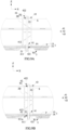
- FIG. 6A is a cross-sectional view taken along a line A-A in FIG. 4 and rotated by 180 degrees, in which a pulling riveting member is not pulling-riveted.
- FIG. 6B is a cross-sectional view corresponding to FIG. 6A , in which the pulling riveting member has been pulling-riveted.
- FIG. 7A is a cross-sectional view corresponding to FIG. 6A , in which the pulling riveting member is rotated by 180 degrees and not pulling-riveted.
- FIG. 7B is a cross-sectional view corresponding to FIG. 7A , in which the pulling riveting member has been pulling-riveted.
- FIG. 8A is a cross-sectional view taken along a line B-B in FIG.
- FIG. 8B is a cross-sectional view corresponding to FIG. 8A , in which the pulling riveting member has been pulling-riveted.
- FIG. 9A is a cross-sectional view corresponding to FIG. 8A , in which the pulling riveting member is rotated by 180 degrees and is not pulling-riveted.
- FIG. 9B is a cross-sectional view corresponding to FIG. 9A , in which the pulling riveting member has been pulling-riveted.
- FIG. 10A is a cross-sectional view taken along a line C-C in FIG. 4 and rotated by 180 degrees with an inner beam showing a bottom wall and the pulling riveting member not pulling-riveted.
- FIG. 10B is a cross-sectional view corresponding to FIG. 10A , in which the pulling riveting member has been pulling-riveted.
- the internal thread tube body 411 passes through the protecting plate 3, the heat exchanging plate 1 and the bottom wall 21 of the lower frame 2, and the internal thread tube body 411 is partially exposed to an outer side of the protecting plate 3, the heat exchanging plate 1 and the bottom wall 21 of the lower frame 2 in the up-down direction Z;
- the external threaded column 421 penetrates from an opposite outer side of the protecting plate 3, the heat exchanging plate 1 and the bottom wall 21 of the lower frame 2 in the up-down direction Z and the external threaded column 421 is in threaded engagement with the internal thread tube body 411;
- the convex portion 412 of the pulling riveting nut 41 abuts against a side of the bottom wall 21 of the lower frame 2 close to the cover portion 422 of the pulling riveting bolt 42 along the up-down direction Z;
- the exposed portion of the internal thread tube body 411 of the pulling riveting nut 41 is configured to form a protruding portion 411a through pulling riveting operation; the protruding
- the pulling riveting bolt 42 may be inserted from below the protecting plate 3 or from above the lower frame 2 along the up-down direction Z, and the pulling riveting nut 41 is opposite to the pulling riveting bolt 42 along the up-down direction Z.
- the external threaded column 421 of the pulling riveting bolt 42 passes through the protecting plate 3 at the first position P1 from below the protecting plate 3 along the up-down direction Z, the external threaded column 421 of the pulling riveting bolt 42 passes through the heat exchanging plate 1, the external threaded column 421 of the pulling riveting bolt 42 is inserted into the bottom wall 21 of the lower frame 2 at the second position P2, and the external threaded column 421 of the pulling riveting bolt 42 is exposed in the hollow cavity S of the lower frame 2; the exposed portion of the internal thread tube body 411 of the pulling riveting nut 41 is positioned in the hollow cavity S of the lower frame 2; the convex portion 412 of the pulling riveting nut 41 is positioned at a lower side of the bottom wall 21 of the lower frame 2 along the up-down direction Z.
- the length of the pulling riveting bolt 42 may be made much shorter than in the case of FIGS. 7A, 7B , 9A and 9B to be described later, therefore the pulling riveting member can be miniaturized.
- the convex portion 412 of the pulling riveting nut 41 is positioned at the lower side of the bottom wall 21 of the lower frame 2 along the up-down direction Z; the convex portion 412 is directly clamped by the bottom wall 21 of the lower frame 2 and the protecting plate 3.
- the convex portion 412 is directly clamped by the heat exchanging plate 1 and the protecting plate 3.
- the protecting plate 3 is provided with a second recessed portion R2, the convex portion 412 is accommodated in the second recessed portion R2, therefore the convex portion 412 can be accommodated without increasing the thickness of the protecting plate 3 to further meet the requirements of lightness.
- the external threaded column 421 of the pulling riveting bolt 42 is inserted into the top wall 22 of the lower frame 2 from above the lower frame 2 along the up-down direction Z, the external threaded column 421 of the pulling riveting bolt 42 passes through the bottom wall 21 of the lower frame 2, the external threaded column 421 of the pulling riveting bolt 42 passes through the heat exchanging plate 1, the external threaded column 421 of the pulling riveting bolt 42 passes through the protecting plate 3 at the first position P1, and the external threaded column 421 of the pulling riveting bolt 42 is exposed below the protecting plate 3; the exposed portion of the internal thread tube body 411 of the pulling riveting nut 41 is positioned below the protecting plate 3.
- the protecting plate 3 is provided with a first recessed portion R1, the exposed portion of the internal thread tube body 411 of the pulling riveting nut 41 is positioned in the first recessed portion R1, thereby saving space, preventing the exposed portion from hitting the human body when carrying the battery box.
- the self-sealing riveting member 4 further comprises a gasket 43, the gasket 43 is sheathed to the external threaded column 421, and clamped between the cover portion 422 of the pulling riveting bolt 42 and the top wall 22 of the lower frame 2 or the protecting plate 3.
- the gasket 43 helps to strengthen the compressive strength of the corresponding position during the pulling riveting process and assists in enhancing the sealing of the corresponding position, especially when the gasket 43 is clamped between the cover portion 422 of the pulling riveting bolt 42 and the protecting plate 3 (due to a total thickness of the protecting plate 3 and the heat exchanging plate 1 in the up-down direction Z is smaller than a total thickness of the lower frame 2 in the up-down direction Z).
- FIG. 11 is an exploded view of another form of a self-sealing riveting member, not of the invention.
- the self-sealing riveting member 4 shown in FIG. 11 is a pressing riveting member.
- the self-sealing riveting member 4 comprises a pressing riveting nut 44 and a pressing riveting bolt 45.
- the pressing riveting nut 44 comprises a hat body 441, a nut embossing teeth 442, a nut guiding groove 443 and an internal thread tube portion 444, the nut embossing teeth 442, the nut guiding groove 443 and the internal thread tube portion 444 are provided to an inner side of an axial direction of the hat body 441.
- the pressing riveting bolt 45 comprises a hat portion 451, a bolt embossing teeth 452 a bolt guiding groove 453 and an external threaded rod portion 454, the bolt embossing teeth 452, the bolt guiding groove 453 and the external threaded rod portion 454 are provided to an inner side of the axial direction of the hat portion 451.
- FIG. 12A is a cross-sectional view of another form of assembling of the self-sealing riveting member with a heat exchanging plate, the inner beam and a protecting plate of the battery box, in which the pressing riveting member is not pressing-riveted.
- FIG. 12B is a cross-sectional view corresponding to FIG. 12A , in which the pressing riveting member is rotated by 180 degrees and is not pressing-riveted.
- the hat portion 451 of the pressing riveting bolt 45 and the hat body 441 of the pressing riveting nut 44 are respectively positioned to opposite sides of the up-down direction Z of the protecting plate 3, the heat exchanging plate 1 and the top wall 22 of the lower frame 2, the internal thread tube portion 444 of the pressing riveting nut 44 and the external threaded rod portion 454 of the pressing riveting bolt 45 pass through the protecting plate 3, the heat exchanging plate 1 and the lower frame 2 and perform engagement, the bolt embossing teeth 452 of the pressing riveting bolt 45 deforms a corresponding position where the bolt embossing teeth 452 of the pressing riveting bolt 45 passes through to be sealed and locked with the bolt guiding groove 453 of the pressing riveting bolt 45, and the nut embossing teeth 442 of the pressing riveting nut 44 deforms a corresponding position where the nut embossing teeth 442 of the pressing riveting nut 44 passes through to be sealed and locked with the nut guiding groove 443 of the pressing riveting nut 44
- the pressing riveting bolt 45 may be inserted from below the protecting plate 3 or above the lower frame 2 along the up-down direction Z, and the pressing riveting nut 44 is opposite to the pressing riveting bolt 45 along the up-down direction.
- the pressing riveting bolt 45 passes through the protecting plate 3 at the first position P1 from below the protecting plate 3 along the up-down direction Z, the pressing riveting bolt 45 passes through the heat exchanging plate 1 and the bottom wall 21 of the lower frame 2, so as to at least seal the position where the pressing riveting bolt 45 passes through the protecting plate 3; the pressing riveting nut 44 is downwardly inserted into the top wall 22 and the bottom wall 21 of the lower frame 2 at the second position P2 along the up-down direction Z, and seals the position where the pressing riveting nut 44 is inserted into the top wall 22.
- the pressing riveting bolt 45 is downwardly inserted into the top wall 22 of the lower frame 2 at the second position P2 along the up-down direction Z and passes through the bottom wall 21 of the lower frame 2, and seals the position where the pressing riveting bolt 45 is inserted into the top wall 22, the pressing riveting nut 44 passes through the protecting plate 3 at the first position P1 from below the protecting plate 3 along the up-down direction Z and the pressing riveting nut 44 passes through the heat exchanging plate 1 and the bottom wall 21 of the lower frame 2, so as to at least seal the position where the pressing riveting nut 44 passes through the protecting plate 3.
- the self-sealing riveting member 4 further comprises a gasket 43, the gasket 43 is sheathed to the external threaded rod portion 454, and clamped between the hat portion 451 of the pressing riveting bolt 45 and the protecting plate 3 or clamped between the hat body 441 of the pressing riveting nut 44 and the protecting plate 3.
- the gasket 43 helps to strengthen the compressive strength of the protecting plate 3 during the pressing riveting process and assists in enhancing the sealing of the protecting plate 3.
Landscapes
- Chemical & Material Sciences (AREA)
- Chemical Kinetics & Catalysis (AREA)
- Electrochemistry (AREA)
- General Chemical & Material Sciences (AREA)
- Engineering & Computer Science (AREA)
- Manufacturing & Machinery (AREA)
- Inorganic Chemistry (AREA)
- Secondary Cells (AREA)
- Battery Mounting, Suspending (AREA)
Claims (7)
- Batteriekasten, umfassend:eine Wärmetauschplatte (1);einen unteren Rahmen (2), der auf der Wärmetauschplatte (1) positioniert ist, wobei der untere Rahmen (2) und die Wärmetauschplatte (1) zusammen einen Aufnahmeraum bilden, der nach oben offen ist und eine Batterie (51) aufnimmt, wobei die Wärmetauschplatte (1) verwendet wird, um die Batterie (51) zu tragen und Wärme mit der Batterie (51) auszutauschen, wobei es sich bei dem unteren Rahmen (2) um eine hohle Struktur mit einem Hohlraum (S) handelt;eine Schutzplatte (3), die unter der Wärmetauschplatte (1) positioniert ist und die Wärmetauschplatte (1) von unten schützt;ein Dichtnietelement (4), das die Schutzplatte (3), die Wärmetauschplatte (1) und den unteren Rahmen (2) aneinander befestigt, wobei das Dichtnietelement (4) entlang einer Aufwärts-Abwärts-Richtung (Z) durch die Schutzplatte (3) und die Wärmetauschplatte (1) läuft und das Dichtnietelement (4) in den unteren Rahmen (2) eingesteckt ist und dem unteren Rahmen (2) mindestens teilweise ausgesetzt ist, wobei das Dichtnietelement (4) Dichten an einer ersten Position (P1) ausführt, an der das Dichtnietelement (4) durch die Schutzplatte (3) läuft, und das Dichtnietelement (4) Dichten an einer zweiten Position (P2) ausführt, an der das Dichtnietelement (4) in den unteren Rahmen (2) eingesteckt ist;dadurch gekennzeichnet, dassder untere Rahmen (2) eine Bodenwand (21) und eine Deckwand (22) umfasst,es sich bei dem Dichtnietelement (4) um ein Zugnietelement handelt, das eine Zugnietmutter (41) und eine Zugnietschraube (42) umfasst,die Zugnietmutter (41) einen Innengewinderöhrenkörper (411) und einen konvexen Abschnitt (412) umfasst, wobei der konvexe Abschnitt (412) den Innengewinderöhrenkörper (411) umgibt und entlang einer Radialrichtung von einem Ende des Innengewinderöhrenkörpers (411) nach außen vorsteht;die Zugnietschraube (42) einen mit einem Außengewinde versehenen Schaft (421) und einen Abdeckabschnitt (422) umfasst, wobei der Abdeckabschnitt (422) den mit einem Außengewinde versehenen Schaft (421) umgibt und entlang der Radialrichtung von einem Ende des mit einem Außengewinde versehenen Schafts (421) nach außen vorsteht;der Innengewinderöhrenkörper (411) durch die Schutzplatte (3), die Wärmetauschplatte (1) und die Bodenwand (21) des unteren Rahmens (2) läuft und der Innengewinderöhrenkörper (411) in der Aufwärts-Abwärts-Richtung (Z) einer Außenseite der Schutzplatte (3), der Wärmetauschplatte (1) und der Bodenwand (21) des unteren Rahmens (2) teilweise ausgesetzt ist;der mit einem Außengewinde versehene Schaft (421) in der Aufwärts-Abwärts-Richtung (Z) von einer gegenüberliegenden äußeren Seite der Schutzplatte (3), der Wärmetauschplatte (1) und der Bodenwand (21) des unteren Rahmens (2) penetriert und sich der mit einem Außengewinde versehene Schaft (421) mit dem Innengewinderöhrenkörper (411) im Gewindeeingriff befindet;der konvexe Abschnitt (412) der Zugnietmutter (41) entlang der Aufwärts-Abwärts-Richtung (Z) an einer Seite der Bodenwand (21) des unteren Rahmens (2) nah bei dem Abdeckabschnitt (422) der Zugnietschraube (42) anliegt;der freiliegende Abschnitt des Innengewinderöhrenkörpers (411) der Zugnietmutter (41) dazu konfiguriert ist, durch einen Zugnietvorgang einen vorstehenden Abschnitt (411a) zu bilden;der vorstehende Abschnitt (411a) des Innengewinderöhrenkörpers (411) der Zugnietmutter (41) und der Abdeckabschnitt (422) der Zugnietschraube (42) Dichten von gegenüberliegenden Seiten der Aufwärts-Abwärts-Richtung (Z) der Schutzplatte (3), der Wärmetauschplatte (1) und der Bodenwand (21) des unteren Rahmens (2) aus ausführen, die erste Position (P1) an der Schutzplatte (3) positioniert ist, die zweite Position (P2) an einer von der Bodenwand (21) und der Deckwand (22) des unteren Rahmens (2), die dem konvexen Abschnitt (412) von oben benachbart ist, positioniert ist.
- Batteriekasten nach Anspruch 1, wobeider mit einem Außengewinde versehene Schaft (421) der Zugnietschraube (42) an der ersten Position (P1) von unter der Schutzplatte (3) entlang der Aufwärts-Abwärts-Richtung (Z) durch die Schutzplatte (3) läuft, der mit einem Außengewinde versehene Schaft (421) der Zugnietschraube (42) durch die Wärmetauschplatte (1) läuft, der mit einem Außengewinde versehene Schaft (421) der Zugnietschraube (42) an der zweiten Position (P2) in die Bodenwand (21) des unteren Rahmens (2) eingesteckt ist und der mit einem Außengewinde versehene Schaft (421) der Zugnietschraube (42) in dem Hohlraum (S) des unteren Rahmens (2) freiliegt;der freiliegende Abschnitt des Innengewinderöhrenkörpers (411) der Zugnietmutter (41) in dem Hohlraum (S) des unteren Rahmens (2) positioniert ist;der konvexe Abschnitt (412) der Zugnietmutter (41) entlang der Aufwärts-Abwärts-Richtung (Z) an einer unteren Seite der Bodenwand (21) des unteren Rahmens (2) positioniert ist.
- Batteriekasten nach Anspruch 1, wobeider mit einem Außengewinde versehene Schaft (421) der Zugnietschraube (42) entlang der Aufwärts-Abwärts-Richtung (Z) an der zweiten Position (P2) von über dem unteren Rahmen (2) in die Deckwand (22) des unteren Rahmens (2) eingesteckt ist, der mit einem Außengewinde versehene Schaft (421) der Zugnietschraube (42) durch die Bodenwand (21) des unteren Rahmens (2) läuft, der mit einem Außengewinde versehene Schaft (421) der Zugnietschraube (42) durch die Wärmetauschplatte (1) läuft, der mit einem Außengewinde versehene Schaft (421) der Zugnietschraube (42) an der ersten Position (P1) durch die Schutzplatte (3) läuft und der mit einem Außengewinde versehene Schaft (421) der Zugnietschraube (42) unter der Schutzplatte (3) freiliegt;der freiliegende Abschnitt des Innengewinderöhrenkörpers (411) der Zugnietmutter (41) unter der Schutzplatte (3) positioniert ist;
- Batteriekasten nach Anspruch 3, wobei
die Schutzplatte (3) mit einem ersten zurückgesetzten Abschnitt (R1) versehen ist, der freiliegende Abschnitt des Innengewinderöhrenkörpers (411) der Zugnietmutter (41) in dem ersten zurückgesetzten Abschnitt (R1) positioniert ist. - Batteriekasten nach Anspruch 3, wobeider konvexe Abschnitt (412) der Zugnietmutter (41) entlang der Aufwärts-Abwärts-Richtung (Z) an der unteren Seite der Bodenwand (21) des unteren Rahmens (2) positioniert ist,der konvexe Abschnitt (412) direkt von der Bodenwand (21) des unteren Rahmens (2) und der Schutzplatte (3) geklemmt wird.
- Batteriekasten nach Anspruch 3, wobei
der konvexe Abschnitt (412) direkt von der Wärmetauschplatte (1) und der Schutzplatte (3) geklemmt wird. - Batteriekasten nach Anspruch 6, wobei
die Schutzplatte (3) mit einem zweiten zurückgesetzten Abschnitt (R2) versehen ist, der konvexe Abschnitt (412) in dem zweiten zurückgesetzten Abschnitt (R2) aufgenommen ist.
Applications Claiming Priority (1)
| Application Number | Priority Date | Filing Date | Title |
|---|---|---|---|
| CN201822266524.1U CN209183581U (zh) | 2018-12-29 | 2018-12-29 | 电池箱 |
Publications (2)
| Publication Number | Publication Date |
|---|---|
| EP3675207A1 EP3675207A1 (de) | 2020-07-01 |
| EP3675207B1 true EP3675207B1 (de) | 2024-03-06 |
Family
ID=67378172
Family Applications (1)
| Application Number | Title | Priority Date | Filing Date |
|---|---|---|---|
| EP19215093.6A Active EP3675207B1 (de) | 2018-12-29 | 2019-12-11 | Batteriekasten |
Country Status (4)
| Country | Link |
|---|---|
| US (1) | US20200212397A1 (de) |
| EP (1) | EP3675207B1 (de) |
| CN (1) | CN209183581U (de) |
| WO (1) | WO2020134980A1 (de) |
Families Citing this family (29)
| Publication number | Priority date | Publication date | Assignee | Title |
|---|---|---|---|---|
| CN209183581U (zh) * | 2018-12-29 | 2019-07-30 | 宁德时代新能源科技股份有限公司 | 电池箱 |
| CN209104331U (zh) | 2018-12-29 | 2019-07-12 | 宁德时代新能源科技股份有限公司 | 电池包 |
| CN111092178A (zh) * | 2019-12-25 | 2020-05-01 | 北京海纳川汽车部件股份有限公司 | 车辆的电池箱和车辆 |
| CN111063843B (zh) * | 2019-12-25 | 2023-01-24 | 北京海纳川汽车部件股份有限公司 | 车辆的电池箱和车辆 |
| FR3107398A1 (fr) * | 2020-02-17 | 2021-08-20 | Valeo Systemes Thermiques | Compartiment pour un équipement susceptible de dégager de la chaleur |
| ES3042835T3 (en) * | 2021-07-29 | 2025-11-24 | Contemporary Amperex Technology Hong Kong Ltd | Battery, electricity-consuming apparatus, method for manufacturing battery and system of manufacturing battery |
| JP7709868B2 (ja) * | 2021-07-29 | 2025-07-17 | ダイムラー トラック エージー | 車両用バッテリパック及び電動トラック |
| CN113594601B (zh) * | 2021-08-06 | 2023-05-09 | 江苏奥特帕斯新能源科技有限公司 | 一种带有底护板的低热辐射液冷电池箱体 |
| CN113675513A (zh) * | 2021-09-03 | 2021-11-19 | 宁波信泰机械有限公司 | 一种复合材料电池箱体结构 |
| CN215955419U (zh) * | 2021-09-27 | 2022-03-04 | 宁德时代新能源科技股份有限公司 | 箱体、电池以及用电装置 |
| CN116487789A (zh) | 2022-01-13 | 2023-07-25 | 宁德时代新能源科技股份有限公司 | 箱体、电池、用电装置以及制备电池的方法和装置 |
| WO2023159642A1 (zh) * | 2022-02-28 | 2023-08-31 | 宁德时代新能源科技股份有限公司 | 铆接组件、电池、用电设备、铆接组件的组装方法及设备 |
| US12275298B2 (en) | 2022-03-23 | 2025-04-15 | Ford Global Technologies, Llc | Traction battery packs with cell-to-pack battery systems housed within irregularly shaped enclosures |
| US12230826B2 (en) | 2022-03-23 | 2025-02-18 | Ford Global Technologies, Llc | Methods for assembling traction battery packs |
| US12567642B2 (en) | 2022-03-23 | 2026-03-03 | Ford Global Technologies, Llc | Shim systems for traction battery packs |
| US12424695B2 (en) | 2022-03-23 | 2025-09-23 | Ford Global Technologies, Llc | Retention assemblies for traction battery packs with cell-to-pack battery systems |
| US12525637B2 (en) | 2022-03-23 | 2026-01-13 | Ford Global Technologies, Llc | Traction battery pack assembling method |
| US12506215B2 (en) | 2022-03-23 | 2025-12-23 | Ford Global Technologies, Llc | Enclosure cover attachment configurations for traction battery packs with cell-to-pack battery systems |
| US12479327B2 (en) | 2022-03-23 | 2025-11-25 | Ford Global Technologies, Llc | Traction battery pack cell stack removal method and battery pack assembly |
| US12374750B2 (en) | 2022-03-23 | 2025-07-29 | Ford Global Technologies, Llc | Traction battery pack assembling method |
| US12603373B2 (en) | 2022-03-23 | 2026-04-14 | Ford Global Technologies, Llc | Traction battery pack assembling method |
| CN217485653U (zh) * | 2022-07-07 | 2022-09-23 | 宁德时代新能源科技股份有限公司 | 电池箱体及具有其的电池和用电设备 |
| US12567624B2 (en) * | 2022-09-16 | 2026-03-03 | Ford Global Technologies, Llc | Thermal insulating joints for traction battery packs |
| CN115207542B (zh) * | 2022-09-16 | 2022-11-18 | 中创新航科技股份有限公司 | 一种电池包外壳及电池包 |
| KR20240083048A (ko) * | 2022-12-02 | 2024-06-11 | 주식회사 엘지에너지솔루션 | 배터리 팩 |
| GB2629394B (en) * | 2023-04-27 | 2026-03-04 | Dyson Technology Ltd | A battery enclosure |
| CN221508320U (zh) * | 2024-05-14 | 2024-08-09 | 宁德时代新能源科技股份有限公司 | 电池及用电装置 |
| CN118231925B (zh) * | 2024-05-24 | 2024-09-27 | 福建祥鑫新能源汽车配件制造有限公司 | 一种电池托盘铝型材内腔压铆紧固件机构 |
| GB2643786A (en) * | 2024-09-03 | 2026-03-04 | Jaguar Land Rover Ltd | Sealing panel assembly for a vehicle battery assembly |
Family Cites Families (10)
| Publication number | Priority date | Publication date | Assignee | Title |
|---|---|---|---|---|
| JP5811168B2 (ja) * | 2013-12-25 | 2015-11-11 | トヨタ自動車株式会社 | 車両用電池搭載構造 |
| CN105336888B (zh) * | 2014-07-17 | 2018-04-24 | 宁德新能源科技有限公司 | 电池模组 |
| CN207165693U (zh) * | 2017-09-15 | 2018-03-30 | 江苏维科新能源科技有限公司 | 一种锂电池组的密封结构 |
| CN107732061A (zh) * | 2017-09-29 | 2018-02-23 | 凌云工业股份有限公司 | 一种用于新能源汽车的集成式水冷动力电池壳体 |
| CN108063202B (zh) * | 2017-12-08 | 2023-11-14 | 江西安驰新能源科技有限公司 | 一种电池箱体 |
| CN207977365U (zh) * | 2018-01-16 | 2018-10-16 | 昆明新能源汽车工程技术中心有限公司 | 电池包和具有该电池包的车辆 |
| CN207818706U (zh) * | 2018-02-08 | 2018-09-04 | 宁德时代新能源科技股份有限公司 | 电池包 |
| CN208093632U (zh) * | 2018-04-24 | 2018-11-13 | 北京新能源汽车股份有限公司 | 电池包下壳体组件 |
| CN208256757U (zh) * | 2018-05-07 | 2018-12-18 | 宁德时代新能源科技股份有限公司 | 围框及电池模组 |
| CN209183581U (zh) * | 2018-12-29 | 2019-07-30 | 宁德时代新能源科技股份有限公司 | 电池箱 |
-
2018
- 2018-12-29 CN CN201822266524.1U patent/CN209183581U/zh active Active
-
2019
- 2019-11-26 US US16/696,936 patent/US20200212397A1/en not_active Abandoned
- 2019-12-06 WO PCT/CN2019/123695 patent/WO2020134980A1/zh not_active Ceased
- 2019-12-11 EP EP19215093.6A patent/EP3675207B1/de active Active
Also Published As
| Publication number | Publication date |
|---|---|
| US20200212397A1 (en) | 2020-07-02 |
| EP3675207A1 (de) | 2020-07-01 |
| WO2020134980A1 (zh) | 2020-07-02 |
| CN209183581U (zh) | 2019-07-30 |
Similar Documents
| Publication | Publication Date | Title |
|---|---|---|
| EP3675207B1 (de) | Batteriekasten | |
| US11258119B2 (en) | Battery box | |
| EP3451413B1 (de) | Einrichtung, batterieeinheit und batteriemodul | |
| US12283674B2 (en) | Battery box | |
| US20220085450A1 (en) | Battery box, battery pack, and vehicle | |
| CN209401682U (zh) | 电池箱 | |
| EP3451407A1 (de) | Rahmen und batteriemodul | |
| EP3506388B1 (de) | Verbundendplatte und batteriemodul | |
| US8974934B2 (en) | Battery module | |
| US12206083B2 (en) | Temperature control component and battery pack | |
| US11476528B2 (en) | Battery box for electric vehicles | |
| CN217062344U (zh) | 挂载机构、电池包组件及车辆 | |
| CN215896539U (zh) | 一种锂电池用光铝片、顶盖及锂电池 | |
| EP4611135A1 (de) | Batterieabdeckung, strombatterie und montageverfahren für batterieabdeckung | |
| US10930916B2 (en) | Composite end plate for battery module and battery module | |
| JP5446690B2 (ja) | 蓄電池 | |
| CN119651010A (zh) | 电池顶盖结构及电池 | |
| CN110612616B (zh) | 固定架、电池模块以及电池包 | |
| KR20260046469A (ko) | 열교환 구조체, 배터리 팩 및 전기 디바이스 | |
| CN220189831U (zh) | 电池箱上盖、电池箱以及电池包 | |
| CN220710427U (zh) | 电池包 | |
| CN213212250U (zh) | 一种新型锂电池滑轨式铝桶 | |
| JP2010115003A (ja) | パワーケーブルカバー | |
| CN222072032U (zh) | 用于电池包的箱体以及电池包 | |
| CN222507797U (zh) | 一种电池的下塑胶组件、盖板组件、电池以及光伏设备 |
Legal Events
| Date | Code | Title | Description |
|---|---|---|---|
| PUAI | Public reference made under article 153(3) epc to a published international application that has entered the european phase |
Free format text: ORIGINAL CODE: 0009012 |
|
| STAA | Information on the status of an ep patent application or granted ep patent |
Free format text: STATUS: REQUEST FOR EXAMINATION WAS MADE |
|
| 17P | Request for examination filed |
Effective date: 20191211 |
|
| AK | Designated contracting states |
Kind code of ref document: A1 Designated state(s): AL AT BE BG CH CY CZ DE DK EE ES FI FR GB GR HR HU IE IS IT LI LT LU LV MC MK MT NL NO PL PT RO RS SE SI SK SM TR |
|
| AX | Request for extension of the european patent |
Extension state: BA ME |
|
| REG | Reference to a national code |
Ref country code: DE Free format text: PREVIOUS MAIN CLASS: H01M0002080000 Ref country code: DE Ref legal event code: R079 Ref document number: 602019047674 Country of ref document: DE Free format text: PREVIOUS MAIN CLASS: H01M0002080000 Ipc: H01M0010655600 |
|
| GRAP | Despatch of communication of intention to grant a patent |
Free format text: ORIGINAL CODE: EPIDOSNIGR1 |
|
| STAA | Information on the status of an ep patent application or granted ep patent |
Free format text: STATUS: GRANT OF PATENT IS INTENDED |
|
| RIC1 | Information provided on ipc code assigned before grant |
Ipc: H01M 10/625 20140101ALN20231109BHEP Ipc: H01M 10/615 20140101ALN20231109BHEP Ipc: H01M 10/613 20140101ALN20231109BHEP Ipc: H01M 50/271 20210101ALI20231109BHEP Ipc: H01M 50/262 20210101ALI20231109BHEP Ipc: H01M 50/231 20210101ALI20231109BHEP Ipc: H01M 50/227 20210101ALI20231109BHEP Ipc: H01M 50/224 20210101ALI20231109BHEP Ipc: H01M 50/211 20210101ALI20231109BHEP Ipc: H01M 50/186 20210101ALI20231109BHEP Ipc: H01M 50/184 20210101ALI20231109BHEP Ipc: H01M 50/24 20210101ALI20231109BHEP Ipc: H01M 10/6556 20140101AFI20231109BHEP |
|
| INTG | Intention to grant announced |
Effective date: 20231123 |
|
| GRAS | Grant fee paid |
Free format text: ORIGINAL CODE: EPIDOSNIGR3 |
|
| GRAA | (expected) grant |
Free format text: ORIGINAL CODE: 0009210 |
|
| STAA | Information on the status of an ep patent application or granted ep patent |
Free format text: STATUS: THE PATENT HAS BEEN GRANTED |
|
| P01 | Opt-out of the competence of the unified patent court (upc) registered |
Effective date: 20240104 |
|
| AK | Designated contracting states |
Kind code of ref document: B1 Designated state(s): AL AT BE BG CH CY CZ DE DK EE ES FI FR GB GR HR HU IE IS IT LI LT LU LV MC MK MT NL NO PL PT RO RS SE SI SK SM TR |
|
| REG | Reference to a national code |
Ref country code: CH Ref legal event code: EP |
|
| REG | Reference to a national code |
Ref country code: DE Ref legal event code: R096 Ref document number: 602019047674 Country of ref document: DE |
|
| REG | Reference to a national code |
Ref country code: IE Ref legal event code: FG4D |
|
| REG | Reference to a national code |
Ref country code: LT Ref legal event code: MG9D |
|
| PG25 | Lapsed in a contracting state [announced via postgrant information from national office to epo] |
Ref country code: LT Free format text: LAPSE BECAUSE OF FAILURE TO SUBMIT A TRANSLATION OF THE DESCRIPTION OR TO PAY THE FEE WITHIN THE PRESCRIBED TIME-LIMIT Effective date: 20240306 |
|
| REG | Reference to a national code |
Ref country code: NL Ref legal event code: MP Effective date: 20240306 |
|
| PG25 | Lapsed in a contracting state [announced via postgrant information from national office to epo] |
Ref country code: GR Free format text: LAPSE BECAUSE OF FAILURE TO SUBMIT A TRANSLATION OF THE DESCRIPTION OR TO PAY THE FEE WITHIN THE PRESCRIBED TIME-LIMIT Effective date: 20240607 |
|
| PG25 | Lapsed in a contracting state [announced via postgrant information from national office to epo] |
Ref country code: HR Free format text: LAPSE BECAUSE OF FAILURE TO SUBMIT A TRANSLATION OF THE DESCRIPTION OR TO PAY THE FEE WITHIN THE PRESCRIBED TIME-LIMIT Effective date: 20240306 Ref country code: RS Free format text: LAPSE BECAUSE OF FAILURE TO SUBMIT A TRANSLATION OF THE DESCRIPTION OR TO PAY THE FEE WITHIN THE PRESCRIBED TIME-LIMIT Effective date: 20240606 |
|
| PG25 | Lapsed in a contracting state [announced via postgrant information from national office to epo] |
Ref country code: ES Free format text: LAPSE BECAUSE OF FAILURE TO SUBMIT A TRANSLATION OF THE DESCRIPTION OR TO PAY THE FEE WITHIN THE PRESCRIBED TIME-LIMIT Effective date: 20240306 |
|
| PG25 | Lapsed in a contracting state [announced via postgrant information from national office to epo] |
Ref country code: RS Free format text: LAPSE BECAUSE OF FAILURE TO SUBMIT A TRANSLATION OF THE DESCRIPTION OR TO PAY THE FEE WITHIN THE PRESCRIBED TIME-LIMIT Effective date: 20240606 Ref country code: NO Free format text: LAPSE BECAUSE OF FAILURE TO SUBMIT A TRANSLATION OF THE DESCRIPTION OR TO PAY THE FEE WITHIN THE PRESCRIBED TIME-LIMIT Effective date: 20240606 Ref country code: LT Free format text: LAPSE BECAUSE OF FAILURE TO SUBMIT A TRANSLATION OF THE DESCRIPTION OR TO PAY THE FEE WITHIN THE PRESCRIBED TIME-LIMIT Effective date: 20240306 Ref country code: HR Free format text: LAPSE BECAUSE OF FAILURE TO SUBMIT A TRANSLATION OF THE DESCRIPTION OR TO PAY THE FEE WITHIN THE PRESCRIBED TIME-LIMIT Effective date: 20240306 Ref country code: GR Free format text: LAPSE BECAUSE OF FAILURE TO SUBMIT A TRANSLATION OF THE DESCRIPTION OR TO PAY THE FEE WITHIN THE PRESCRIBED TIME-LIMIT Effective date: 20240607 Ref country code: FI Free format text: LAPSE BECAUSE OF FAILURE TO SUBMIT A TRANSLATION OF THE DESCRIPTION OR TO PAY THE FEE WITHIN THE PRESCRIBED TIME-LIMIT Effective date: 20240306 Ref country code: ES Free format text: LAPSE BECAUSE OF FAILURE TO SUBMIT A TRANSLATION OF THE DESCRIPTION OR TO PAY THE FEE WITHIN THE PRESCRIBED TIME-LIMIT Effective date: 20240306 Ref country code: BG Free format text: LAPSE BECAUSE OF FAILURE TO SUBMIT A TRANSLATION OF THE DESCRIPTION OR TO PAY THE FEE WITHIN THE PRESCRIBED TIME-LIMIT Effective date: 20240306 |
|
| REG | Reference to a national code |
Ref country code: DE Ref legal event code: R081 Ref document number: 602019047674 Country of ref document: DE Owner name: CONTEMPORARY AMPEREX TECHNOLOGY (HONG KONG) LI, HK Free format text: FORMER OWNER: CONTEMPORARY AMPEREX TECHNOLOGY CO., LIMITED, NINGDE CITY, FUJIAN, CN |
|
| REG | Reference to a national code |
Ref country code: AT Ref legal event code: MK05 Ref document number: 1664440 Country of ref document: AT Kind code of ref document: T Effective date: 20240306 |
|
| PG25 | Lapsed in a contracting state [announced via postgrant information from national office to epo] |
Ref country code: SE Free format text: LAPSE BECAUSE OF FAILURE TO SUBMIT A TRANSLATION OF THE DESCRIPTION OR TO PAY THE FEE WITHIN THE PRESCRIBED TIME-LIMIT Effective date: 20240306 Ref country code: LV Free format text: LAPSE BECAUSE OF FAILURE TO SUBMIT A TRANSLATION OF THE DESCRIPTION OR TO PAY THE FEE WITHIN THE PRESCRIBED TIME-LIMIT Effective date: 20240306 |
|
| PG25 | Lapsed in a contracting state [announced via postgrant information from national office to epo] |
Ref country code: NL Free format text: LAPSE BECAUSE OF FAILURE TO SUBMIT A TRANSLATION OF THE DESCRIPTION OR TO PAY THE FEE WITHIN THE PRESCRIBED TIME-LIMIT Effective date: 20240306 |
|
| REG | Reference to a national code |
Ref country code: GB Ref legal event code: 732E Free format text: REGISTERED BETWEEN 20240808 AND 20240814 |
|
| PG25 | Lapsed in a contracting state [announced via postgrant information from national office to epo] |
Ref country code: NL Free format text: LAPSE BECAUSE OF FAILURE TO SUBMIT A TRANSLATION OF THE DESCRIPTION OR TO PAY THE FEE WITHIN THE PRESCRIBED TIME-LIMIT Effective date: 20240306 |
|
| RAP2 | Party data changed (patent owner data changed or rights of a patent transferred) |
Owner name: CONTEMPORARY AMPEREX TECHNOLOGY(HONG KONG) LIMITED |
|
| PG25 | Lapsed in a contracting state [announced via postgrant information from national office to epo] |
Ref country code: IS Free format text: LAPSE BECAUSE OF FAILURE TO SUBMIT A TRANSLATION OF THE DESCRIPTION OR TO PAY THE FEE WITHIN THE PRESCRIBED TIME-LIMIT Effective date: 20240706 |
|
| PG25 | Lapsed in a contracting state [announced via postgrant information from national office to epo] |
Ref country code: SM Free format text: LAPSE BECAUSE OF FAILURE TO SUBMIT A TRANSLATION OF THE DESCRIPTION OR TO PAY THE FEE WITHIN THE PRESCRIBED TIME-LIMIT Effective date: 20240306 Ref country code: PT Free format text: LAPSE BECAUSE OF FAILURE TO SUBMIT A TRANSLATION OF THE DESCRIPTION OR TO PAY THE FEE WITHIN THE PRESCRIBED TIME-LIMIT Effective date: 20240708 |
|
| PG25 | Lapsed in a contracting state [announced via postgrant information from national office to epo] |
Ref country code: EE Free format text: LAPSE BECAUSE OF FAILURE TO SUBMIT A TRANSLATION OF THE DESCRIPTION OR TO PAY THE FEE WITHIN THE PRESCRIBED TIME-LIMIT Effective date: 20240306 Ref country code: CZ Free format text: LAPSE BECAUSE OF FAILURE TO SUBMIT A TRANSLATION OF THE DESCRIPTION OR TO PAY THE FEE WITHIN THE PRESCRIBED TIME-LIMIT Effective date: 20240306 |
|
| PG25 | Lapsed in a contracting state [announced via postgrant information from national office to epo] |
Ref country code: AT Free format text: LAPSE BECAUSE OF FAILURE TO SUBMIT A TRANSLATION OF THE DESCRIPTION OR TO PAY THE FEE WITHIN THE PRESCRIBED TIME-LIMIT Effective date: 20240306 |
|
| PG25 | Lapsed in a contracting state [announced via postgrant information from national office to epo] |
Ref country code: PL Free format text: LAPSE BECAUSE OF FAILURE TO SUBMIT A TRANSLATION OF THE DESCRIPTION OR TO PAY THE FEE WITHIN THE PRESCRIBED TIME-LIMIT Effective date: 20240306 |
|
| PG25 | Lapsed in a contracting state [announced via postgrant information from national office to epo] |
Ref country code: SK Free format text: LAPSE BECAUSE OF FAILURE TO SUBMIT A TRANSLATION OF THE DESCRIPTION OR TO PAY THE FEE WITHIN THE PRESCRIBED TIME-LIMIT Effective date: 20240306 |
|
| PG25 | Lapsed in a contracting state [announced via postgrant information from national office to epo] |
Ref country code: SM Free format text: LAPSE BECAUSE OF FAILURE TO SUBMIT A TRANSLATION OF THE DESCRIPTION OR TO PAY THE FEE WITHIN THE PRESCRIBED TIME-LIMIT Effective date: 20240306 Ref country code: SK Free format text: LAPSE BECAUSE OF FAILURE TO SUBMIT A TRANSLATION OF THE DESCRIPTION OR TO PAY THE FEE WITHIN THE PRESCRIBED TIME-LIMIT Effective date: 20240306 Ref country code: RO Free format text: LAPSE BECAUSE OF FAILURE TO SUBMIT A TRANSLATION OF THE DESCRIPTION OR TO PAY THE FEE WITHIN THE PRESCRIBED TIME-LIMIT Effective date: 20240306 Ref country code: PT Free format text: LAPSE BECAUSE OF FAILURE TO SUBMIT A TRANSLATION OF THE DESCRIPTION OR TO PAY THE FEE WITHIN THE PRESCRIBED TIME-LIMIT Effective date: 20240708 Ref country code: PL Free format text: LAPSE BECAUSE OF FAILURE TO SUBMIT A TRANSLATION OF THE DESCRIPTION OR TO PAY THE FEE WITHIN THE PRESCRIBED TIME-LIMIT Effective date: 20240306 Ref country code: IS Free format text: LAPSE BECAUSE OF FAILURE TO SUBMIT A TRANSLATION OF THE DESCRIPTION OR TO PAY THE FEE WITHIN THE PRESCRIBED TIME-LIMIT Effective date: 20240706 Ref country code: EE Free format text: LAPSE BECAUSE OF FAILURE TO SUBMIT A TRANSLATION OF THE DESCRIPTION OR TO PAY THE FEE WITHIN THE PRESCRIBED TIME-LIMIT Effective date: 20240306 Ref country code: CZ Free format text: LAPSE BECAUSE OF FAILURE TO SUBMIT A TRANSLATION OF THE DESCRIPTION OR TO PAY THE FEE WITHIN THE PRESCRIBED TIME-LIMIT Effective date: 20240306 Ref country code: AT Free format text: LAPSE BECAUSE OF FAILURE TO SUBMIT A TRANSLATION OF THE DESCRIPTION OR TO PAY THE FEE WITHIN THE PRESCRIBED TIME-LIMIT Effective date: 20240306 |
|
| PG25 | Lapsed in a contracting state [announced via postgrant information from national office to epo] |
Ref country code: IT Free format text: LAPSE BECAUSE OF FAILURE TO SUBMIT A TRANSLATION OF THE DESCRIPTION OR TO PAY THE FEE WITHIN THE PRESCRIBED TIME-LIMIT Effective date: 20240306 |
|
| REG | Reference to a national code |
Ref country code: DE Ref legal event code: R097 Ref document number: 602019047674 Country of ref document: DE |
|
| PG25 | Lapsed in a contracting state [announced via postgrant information from national office to epo] |
Ref country code: IT Free format text: LAPSE BECAUSE OF FAILURE TO SUBMIT A TRANSLATION OF THE DESCRIPTION OR TO PAY THE FEE WITHIN THE PRESCRIBED TIME-LIMIT Effective date: 20240306 |
|
| PLBE | No opposition filed within time limit |
Free format text: ORIGINAL CODE: 0009261 |
|
| STAA | Information on the status of an ep patent application or granted ep patent |
Free format text: STATUS: NO OPPOSITION FILED WITHIN TIME LIMIT |
|
| PG25 | Lapsed in a contracting state [announced via postgrant information from national office to epo] |
Ref country code: DK Free format text: LAPSE BECAUSE OF FAILURE TO SUBMIT A TRANSLATION OF THE DESCRIPTION OR TO PAY THE FEE WITHIN THE PRESCRIBED TIME-LIMIT Effective date: 20240306 |
|
| PG25 | Lapsed in a contracting state [announced via postgrant information from national office to epo] |
Ref country code: DK Free format text: LAPSE BECAUSE OF FAILURE TO SUBMIT A TRANSLATION OF THE DESCRIPTION OR TO PAY THE FEE WITHIN THE PRESCRIBED TIME-LIMIT Effective date: 20240306 |
|
| 26N | No opposition filed |
Effective date: 20241209 |
|
| PG25 | Lapsed in a contracting state [announced via postgrant information from national office to epo] |
Ref country code: SI Free format text: LAPSE BECAUSE OF FAILURE TO SUBMIT A TRANSLATION OF THE DESCRIPTION OR TO PAY THE FEE WITHIN THE PRESCRIBED TIME-LIMIT Effective date: 20240306 |
|
| PG25 | Lapsed in a contracting state [announced via postgrant information from national office to epo] |
Ref country code: MC Free format text: LAPSE BECAUSE OF FAILURE TO SUBMIT A TRANSLATION OF THE DESCRIPTION OR TO PAY THE FEE WITHIN THE PRESCRIBED TIME-LIMIT Effective date: 20240306 |
|
| REG | Reference to a national code |
Ref country code: CH Ref legal event code: PL |
|
| PG25 | Lapsed in a contracting state [announced via postgrant information from national office to epo] |
Ref country code: LU Free format text: LAPSE BECAUSE OF NON-PAYMENT OF DUE FEES Effective date: 20241211 |
|
| REG | Reference to a national code |
Ref country code: BE Ref legal event code: MM Effective date: 20241231 |
|
| PG25 | Lapsed in a contracting state [announced via postgrant information from national office to epo] |
Ref country code: BE Free format text: LAPSE BECAUSE OF NON-PAYMENT OF DUE FEES Effective date: 20241231 |
|
| PG25 | Lapsed in a contracting state [announced via postgrant information from national office to epo] |
Ref country code: CH Free format text: LAPSE BECAUSE OF NON-PAYMENT OF DUE FEES Effective date: 20241231 |
|
| PG25 | Lapsed in a contracting state [announced via postgrant information from national office to epo] |
Ref country code: IE Free format text: LAPSE BECAUSE OF NON-PAYMENT OF DUE FEES Effective date: 20241211 |
|
| PGFP | Annual fee paid to national office [announced via postgrant information from national office to epo] |
Ref country code: DE Payment date: 20251212 Year of fee payment: 7 |
|
| PGFP | Annual fee paid to national office [announced via postgrant information from national office to epo] |
Ref country code: GB Payment date: 20251211 Year of fee payment: 7 |
|
| PGFP | Annual fee paid to national office [announced via postgrant information from national office to epo] |
Ref country code: FR Payment date: 20251212 Year of fee payment: 7 |