EP3674534B1 - Ansauglufttemperatursteuerungsvorrichtung für motor, motor, fahrzeug, verfahren zur steuerung des motors und computerprogrammprodukt - Google Patents
Ansauglufttemperatursteuerungsvorrichtung für motor, motor, fahrzeug, verfahren zur steuerung des motors und computerprogrammprodukt Download PDFInfo
- Publication number
- EP3674534B1 EP3674534B1 EP19218543.7A EP19218543A EP3674534B1 EP 3674534 B1 EP3674534 B1 EP 3674534B1 EP 19218543 A EP19218543 A EP 19218543A EP 3674534 B1 EP3674534 B1 EP 3674534B1
- Authority
- EP
- European Patent Office
- Prior art keywords
- air
- intake
- engine
- operating range
- engine body
- Prior art date
- Legal status (The legal status is an assumption and is not a legal conclusion. Google has not performed a legal analysis and makes no representation as to the accuracy of the status listed.)
- Active
Links
Images




Classifications
-
- F—MECHANICAL ENGINEERING; LIGHTING; HEATING; WEAPONS; BLASTING
- F02—COMBUSTION ENGINES; HOT-GAS OR COMBUSTION-PRODUCT ENGINE PLANTS
- F02D—CONTROLLING COMBUSTION ENGINES
- F02D41/00—Electrical control of supply of combustible mixture or its constituents
- F02D41/0002—Controlling intake air
-
- F—MECHANICAL ENGINEERING; LIGHTING; HEATING; WEAPONS; BLASTING
- F02—COMBUSTION ENGINES; HOT-GAS OR COMBUSTION-PRODUCT ENGINE PLANTS
- F02D—CONTROLLING COMBUSTION ENGINES
- F02D41/00—Electrical control of supply of combustible mixture or its constituents
- F02D41/30—Controlling fuel injection
- F02D41/3011—Controlling fuel injection according to or using specific or several modes of combustion
- F02D41/3017—Controlling fuel injection according to or using specific or several modes of combustion characterised by the mode(s) being used
- F02D41/3035—Controlling fuel injection according to or using specific or several modes of combustion characterised by the mode(s) being used a mode being the premixed charge compression-ignition mode
- F02D41/3041—Controlling fuel injection according to or using specific or several modes of combustion characterised by the mode(s) being used a mode being the premixed charge compression-ignition mode with means for triggering compression ignition, e.g. spark plug
-
- B—PERFORMING OPERATIONS; TRANSPORTING
- B60—VEHICLES IN GENERAL
- B60K—ARRANGEMENT OR MOUNTING OF PROPULSION UNITS OR OF TRANSMISSIONS IN VEHICLES; ARRANGEMENT OR MOUNTING OF PLURAL DIVERSE PRIME-MOVERS IN VEHICLES; AUXILIARY DRIVES FOR VEHICLES; INSTRUMENTATION OR DASHBOARDS FOR VEHICLES; ARRANGEMENTS IN CONNECTION WITH COOLING, AIR INTAKE, GAS EXHAUST OR FUEL SUPPLY OF PROPULSION UNITS IN VEHICLES
- B60K11/00—Arrangement in connection with cooling of propulsion units
- B60K11/02—Arrangement in connection with cooling of propulsion units with liquid cooling
- B60K11/04—Arrangement or mounting of radiators, radiator shutters, or radiator blinds
-
- F—MECHANICAL ENGINEERING; LIGHTING; HEATING; WEAPONS; BLASTING
- F01—MACHINES OR ENGINES IN GENERAL; ENGINE PLANTS IN GENERAL; STEAM ENGINES
- F01P—COOLING OF MACHINES OR ENGINES IN GENERAL; COOLING OF INTERNAL-COMBUSTION ENGINES
- F01P3/00—Liquid cooling
- F01P3/18—Arrangements or mounting of liquid-to-air heat-exchangers
-
- F—MECHANICAL ENGINEERING; LIGHTING; HEATING; WEAPONS; BLASTING
- F01—MACHINES OR ENGINES IN GENERAL; ENGINE PLANTS IN GENERAL; STEAM ENGINES
- F01P—COOLING OF MACHINES OR ENGINES IN GENERAL; COOLING OF INTERNAL-COMBUSTION ENGINES
- F01P5/00—Pumping cooling-air or liquid coolants
- F01P5/02—Pumping cooling-air; Arrangements of cooling-air pumps, e.g. fans or blowers
- F01P5/06—Guiding or ducting air to, or from, ducted fans
-
- F—MECHANICAL ENGINEERING; LIGHTING; HEATING; WEAPONS; BLASTING
- F01—MACHINES OR ENGINES IN GENERAL; ENGINE PLANTS IN GENERAL; STEAM ENGINES
- F01P—COOLING OF MACHINES OR ENGINES IN GENERAL; COOLING OF INTERNAL-COMBUSTION ENGINES
- F01P7/00—Controlling of coolant flow
- F01P7/14—Controlling of coolant flow the coolant being liquid
-
- F—MECHANICAL ENGINEERING; LIGHTING; HEATING; WEAPONS; BLASTING
- F01—MACHINES OR ENGINES IN GENERAL; ENGINE PLANTS IN GENERAL; STEAM ENGINES
- F01P—COOLING OF MACHINES OR ENGINES IN GENERAL; COOLING OF INTERNAL-COMBUSTION ENGINES
- F01P7/00—Controlling of coolant flow
- F01P7/14—Controlling of coolant flow the coolant being liquid
- F01P7/16—Controlling of coolant flow the coolant being liquid by thermostatic control
- F01P7/164—Controlling of coolant flow the coolant being liquid by thermostatic control by varying pump speed
-
- F—MECHANICAL ENGINEERING; LIGHTING; HEATING; WEAPONS; BLASTING
- F01—MACHINES OR ENGINES IN GENERAL; ENGINE PLANTS IN GENERAL; STEAM ENGINES
- F01P—COOLING OF MACHINES OR ENGINES IN GENERAL; COOLING OF INTERNAL-COMBUSTION ENGINES
- F01P7/00—Controlling of coolant flow
- F01P7/14—Controlling of coolant flow the coolant being liquid
- F01P7/16—Controlling of coolant flow the coolant being liquid by thermostatic control
- F01P7/167—Controlling of coolant flow the coolant being liquid by thermostatic control by adjusting the pre-set temperature according to engine parameters, e.g. engine load, engine speed
-
- F—MECHANICAL ENGINEERING; LIGHTING; HEATING; WEAPONS; BLASTING
- F02—COMBUSTION ENGINES; HOT-GAS OR COMBUSTION-PRODUCT ENGINE PLANTS
- F02B—INTERNAL-COMBUSTION PISTON ENGINES; COMBUSTION ENGINES IN GENERAL
- F02B11/00—Engines characterised by both fuel-air mixture compression and air compression, or characterised by both positive ignition and compression ignition, e.g. in different cylinders
-
- F—MECHANICAL ENGINEERING; LIGHTING; HEATING; WEAPONS; BLASTING
- F02—COMBUSTION ENGINES; HOT-GAS OR COMBUSTION-PRODUCT ENGINE PLANTS
- F02B—INTERNAL-COMBUSTION PISTON ENGINES; COMBUSTION ENGINES IN GENERAL
- F02B29/00—Engines characterised by provision for charging or scavenging not provided for in groups F02B25/00, F02B27/00 or F02B33/00 - F02B39/00; Details thereof
- F02B29/04—Cooling of air intake supply
- F02B29/0406—Layout of the intake air cooling or coolant circuit
- F02B29/0437—Liquid cooled heat exchangers
- F02B29/0443—Layout of the coolant or refrigerant circuit
-
- F—MECHANICAL ENGINEERING; LIGHTING; HEATING; WEAPONS; BLASTING
- F02—COMBUSTION ENGINES; HOT-GAS OR COMBUSTION-PRODUCT ENGINE PLANTS
- F02B—INTERNAL-COMBUSTION PISTON ENGINES; COMBUSTION ENGINES IN GENERAL
- F02B9/00—Engines characterised by other types of ignition
- F02B9/02—Engines characterised by other types of ignition with compression ignition
-
- F—MECHANICAL ENGINEERING; LIGHTING; HEATING; WEAPONS; BLASTING
- F02—COMBUSTION ENGINES; HOT-GAS OR COMBUSTION-PRODUCT ENGINE PLANTS
- F02D—CONTROLLING COMBUSTION ENGINES
- F02D41/00—Electrical control of supply of combustible mixture or its constituents
- F02D41/0002—Controlling intake air
- F02D41/0007—Controlling intake air for control of turbo-charged or super-charged engines
-
- F—MECHANICAL ENGINEERING; LIGHTING; HEATING; WEAPONS; BLASTING
- F02—COMBUSTION ENGINES; HOT-GAS OR COMBUSTION-PRODUCT ENGINE PLANTS
- F02D—CONTROLLING COMBUSTION ENGINES
- F02D41/00—Electrical control of supply of combustible mixture or its constituents
- F02D41/02—Circuit arrangements for generating control signals
- F02D41/04—Introducing corrections for particular operating conditions
- F02D41/06—Introducing corrections for particular operating conditions for engine starting or warming up
- F02D41/068—Introducing corrections for particular operating conditions for engine starting or warming up for warming-up
-
- F—MECHANICAL ENGINEERING; LIGHTING; HEATING; WEAPONS; BLASTING
- F02—COMBUSTION ENGINES; HOT-GAS OR COMBUSTION-PRODUCT ENGINE PLANTS
- F02M—SUPPLYING COMBUSTION ENGINES IN GENERAL WITH COMBUSTIBLE MIXTURES OR CONSTITUENTS THEREOF
- F02M31/00—Apparatus for thermally treating combustion-air, fuel, or fuel-air mixture
- F02M31/02—Apparatus for thermally treating combustion-air, fuel, or fuel-air mixture for heating
- F02M31/04—Apparatus for thermally treating combustion-air, fuel, or fuel-air mixture for heating combustion-air or fuel-air mixture
- F02M31/042—Combustion air
-
- F—MECHANICAL ENGINEERING; LIGHTING; HEATING; WEAPONS; BLASTING
- F02—COMBUSTION ENGINES; HOT-GAS OR COMBUSTION-PRODUCT ENGINE PLANTS
- F02M—SUPPLYING COMBUSTION ENGINES IN GENERAL WITH COMBUSTIBLE MIXTURES OR CONSTITUENTS THEREOF
- F02M35/00—Combustion-air cleaners, air intakes, intake silencers, or induction systems specially adapted for, or arranged on, internal-combustion engines
- F02M35/10—Air intakes; Induction systems
- F02M35/10006—Air intakes; Induction systems characterised by the position of elements of the air intake system in direction of the air intake flow, i.e. between ambient air inlet and supply to the combustion chamber
- F02M35/10013—Means upstream of the air filter; Connection to the ambient air
-
- F—MECHANICAL ENGINEERING; LIGHTING; HEATING; WEAPONS; BLASTING
- F02—COMBUSTION ENGINES; HOT-GAS OR COMBUSTION-PRODUCT ENGINE PLANTS
- F02M—SUPPLYING COMBUSTION ENGINES IN GENERAL WITH COMBUSTIBLE MIXTURES OR CONSTITUENTS THEREOF
- F02M35/00—Combustion-air cleaners, air intakes, intake silencers, or induction systems specially adapted for, or arranged on, internal-combustion engines
- F02M35/10—Air intakes; Induction systems
- F02M35/10242—Devices or means connected to or integrated into air intakes; Air intakes combined with other engine or vehicle parts
- F02M35/10255—Arrangements of valves; Multi-way valves
-
- F—MECHANICAL ENGINEERING; LIGHTING; HEATING; WEAPONS; BLASTING
- F02—COMBUSTION ENGINES; HOT-GAS OR COMBUSTION-PRODUCT ENGINE PLANTS
- F02M—SUPPLYING COMBUSTION ENGINES IN GENERAL WITH COMBUSTIBLE MIXTURES OR CONSTITUENTS THEREOF
- F02M35/00—Combustion-air cleaners, air intakes, intake silencers, or induction systems specially adapted for, or arranged on, internal-combustion engines
- F02M35/10—Air intakes; Induction systems
- F02M35/10242—Devices or means connected to or integrated into air intakes; Air intakes combined with other engine or vehicle parts
- F02M35/10268—Heating, cooling or thermal insulating means
-
- F—MECHANICAL ENGINEERING; LIGHTING; HEATING; WEAPONS; BLASTING
- F02—COMBUSTION ENGINES; HOT-GAS OR COMBUSTION-PRODUCT ENGINE PLANTS
- F02M—SUPPLYING COMBUSTION ENGINES IN GENERAL WITH COMBUSTIBLE MIXTURES OR CONSTITUENTS THEREOF
- F02M35/00—Combustion-air cleaners, air intakes, intake silencers, or induction systems specially adapted for, or arranged on, internal-combustion engines
- F02M35/16—Combustion-air cleaners, air intakes, intake silencers, or induction systems specially adapted for, or arranged on, internal-combustion engines characterised by use in vehicles
- F02M35/161—Arrangement of the air intake system in the engine compartment, e.g. with respect to the bonnet or the vehicle front face
-
- B—PERFORMING OPERATIONS; TRANSPORTING
- B60—VEHICLES IN GENERAL
- B60K—ARRANGEMENT OR MOUNTING OF PROPULSION UNITS OR OF TRANSMISSIONS IN VEHICLES; ARRANGEMENT OR MOUNTING OF PLURAL DIVERSE PRIME-MOVERS IN VEHICLES; AUXILIARY DRIVES FOR VEHICLES; INSTRUMENTATION OR DASHBOARDS FOR VEHICLES; ARRANGEMENTS IN CONNECTION WITH COOLING, AIR INTAKE, GAS EXHAUST OR FUEL SUPPLY OF PROPULSION UNITS IN VEHICLES
- B60K11/00—Arrangement in connection with cooling of propulsion units
- B60K11/08—Air inlets for cooling; Shutters or blinds therefor
- B60K11/085—Air inlets for cooling; Shutters or blinds therefor with adjustable shutters or blinds
-
- B—PERFORMING OPERATIONS; TRANSPORTING
- B60—VEHICLES IN GENERAL
- B60K—ARRANGEMENT OR MOUNTING OF PROPULSION UNITS OR OF TRANSMISSIONS IN VEHICLES; ARRANGEMENT OR MOUNTING OF PLURAL DIVERSE PRIME-MOVERS IN VEHICLES; AUXILIARY DRIVES FOR VEHICLES; INSTRUMENTATION OR DASHBOARDS FOR VEHICLES; ARRANGEMENTS IN CONNECTION WITH COOLING, AIR INTAKE, GAS EXHAUST OR FUEL SUPPLY OF PROPULSION UNITS IN VEHICLES
- B60K13/00—Arrangement in connection with combustion air intake or gas exhaust of propulsion units
- B60K13/02—Arrangement in connection with combustion air intake or gas exhaust of propulsion units concerning intake
-
- F—MECHANICAL ENGINEERING; LIGHTING; HEATING; WEAPONS; BLASTING
- F01—MACHINES OR ENGINES IN GENERAL; ENGINE PLANTS IN GENERAL; STEAM ENGINES
- F01P—COOLING OF MACHINES OR ENGINES IN GENERAL; COOLING OF INTERNAL-COMBUSTION ENGINES
- F01P3/00—Liquid cooling
- F01P3/18—Arrangements or mounting of liquid-to-air heat-exchangers
- F01P2003/185—Arrangements or mounting of liquid-to-air heat-exchangers arranged in parallel
-
- F—MECHANICAL ENGINEERING; LIGHTING; HEATING; WEAPONS; BLASTING
- F01—MACHINES OR ENGINES IN GENERAL; ENGINE PLANTS IN GENERAL; STEAM ENGINES
- F01P—COOLING OF MACHINES OR ENGINES IN GENERAL; COOLING OF INTERNAL-COMBUSTION ENGINES
- F01P5/00—Pumping cooling-air or liquid coolants
- F01P5/10—Pumping liquid coolant; Arrangements of coolant pumps
- F01P2005/105—Using two or more pumps
-
- F—MECHANICAL ENGINEERING; LIGHTING; HEATING; WEAPONS; BLASTING
- F01—MACHINES OR ENGINES IN GENERAL; ENGINE PLANTS IN GENERAL; STEAM ENGINES
- F01P—COOLING OF MACHINES OR ENGINES IN GENERAL; COOLING OF INTERNAL-COMBUSTION ENGINES
- F01P2025/00—Measuring
- F01P2025/08—Temperature
- F01P2025/42—Intake manifold temperature
-
- F—MECHANICAL ENGINEERING; LIGHTING; HEATING; WEAPONS; BLASTING
- F01—MACHINES OR ENGINES IN GENERAL; ENGINE PLANTS IN GENERAL; STEAM ENGINES
- F01P—COOLING OF MACHINES OR ENGINES IN GENERAL; COOLING OF INTERNAL-COMBUSTION ENGINES
- F01P2060/00—Cooling circuits using auxiliaries
- F01P2060/02—Intercooler
-
- F—MECHANICAL ENGINEERING; LIGHTING; HEATING; WEAPONS; BLASTING
- F01—MACHINES OR ENGINES IN GENERAL; ENGINE PLANTS IN GENERAL; STEAM ENGINES
- F01P—COOLING OF MACHINES OR ENGINES IN GENERAL; COOLING OF INTERNAL-COMBUSTION ENGINES
- F01P2060/00—Cooling circuits using auxiliaries
- F01P2060/12—Turbo charger
-
- F—MECHANICAL ENGINEERING; LIGHTING; HEATING; WEAPONS; BLASTING
- F01—MACHINES OR ENGINES IN GENERAL; ENGINE PLANTS IN GENERAL; STEAM ENGINES
- F01P—COOLING OF MACHINES OR ENGINES IN GENERAL; COOLING OF INTERNAL-COMBUSTION ENGINES
- F01P2070/00—Details
- F01P2070/04—Details using electrical heating elements
-
- F—MECHANICAL ENGINEERING; LIGHTING; HEATING; WEAPONS; BLASTING
- F01—MACHINES OR ENGINES IN GENERAL; ENGINE PLANTS IN GENERAL; STEAM ENGINES
- F01P—COOLING OF MACHINES OR ENGINES IN GENERAL; COOLING OF INTERNAL-COMBUSTION ENGINES
- F01P7/00—Controlling of coolant flow
- F01P7/02—Controlling of coolant flow the coolant being cooling-air
- F01P7/04—Controlling of coolant flow the coolant being cooling-air by varying pump speed, e.g. by changing pump-drive gear ratio
- F01P7/048—Controlling of coolant flow the coolant being cooling-air by varying pump speed, e.g. by changing pump-drive gear ratio using electrical drives
-
- F—MECHANICAL ENGINEERING; LIGHTING; HEATING; WEAPONS; BLASTING
- F01—MACHINES OR ENGINES IN GENERAL; ENGINE PLANTS IN GENERAL; STEAM ENGINES
- F01P—COOLING OF MACHINES OR ENGINES IN GENERAL; COOLING OF INTERNAL-COMBUSTION ENGINES
- F01P7/00—Controlling of coolant flow
- F01P7/02—Controlling of coolant flow the coolant being cooling-air
- F01P7/10—Controlling of coolant flow the coolant being cooling-air by throttling amount of air flowing through liquid-to-air heat exchangers
-
- F—MECHANICAL ENGINEERING; LIGHTING; HEATING; WEAPONS; BLASTING
- F02—COMBUSTION ENGINES; HOT-GAS OR COMBUSTION-PRODUCT ENGINE PLANTS
- F02D—CONTROLLING COMBUSTION ENGINES
- F02D2200/00—Input parameters for engine control
- F02D2200/02—Input parameters for engine control the parameters being related to the engine
- F02D2200/04—Engine intake system parameters
- F02D2200/0414—Air temperature
-
- Y—GENERAL TAGGING OF NEW TECHNOLOGICAL DEVELOPMENTS; GENERAL TAGGING OF CROSS-SECTIONAL TECHNOLOGIES SPANNING OVER SEVERAL SECTIONS OF THE IPC; TECHNICAL SUBJECTS COVERED BY FORMER USPC CROSS-REFERENCE ART COLLECTIONS [XRACs] AND DIGESTS
- Y02—TECHNOLOGIES OR APPLICATIONS FOR MITIGATION OR ADAPTATION AGAINST CLIMATE CHANGE
- Y02T—CLIMATE CHANGE MITIGATION TECHNOLOGIES RELATED TO TRANSPORTATION
- Y02T10/00—Road transport of goods or passengers
- Y02T10/10—Internal combustion engine [ICE] based vehicles
- Y02T10/12—Improving ICE efficiencies
-
- Y—GENERAL TAGGING OF NEW TECHNOLOGICAL DEVELOPMENTS; GENERAL TAGGING OF CROSS-SECTIONAL TECHNOLOGIES SPANNING OVER SEVERAL SECTIONS OF THE IPC; TECHNICAL SUBJECTS COVERED BY FORMER USPC CROSS-REFERENCE ART COLLECTIONS [XRACs] AND DIGESTS
- Y02—TECHNOLOGIES OR APPLICATIONS FOR MITIGATION OR ADAPTATION AGAINST CLIMATE CHANGE
- Y02T—CLIMATE CHANGE MITIGATION TECHNOLOGIES RELATED TO TRANSPORTATION
- Y02T10/00—Road transport of goods or passengers
- Y02T10/80—Technologies aiming to reduce greenhouse gasses emissions common to all road transportation technologies
- Y02T10/88—Optimized components or subsystems, e.g. lighting, actively controlled glasses
Definitions
- JP2007-056773A discloses a controlling device for an internal combustion engine including a means for starting intake air heating by a heater provided to an intake passage when a switching request from jump-spark-ignition combustion to compression ignition combustion is received, a means for increasing an exhaust gas recirculation (EGR) rate by an EGR device during the jump-spark-ignition combustion in response to an increase in the intake air temperature by the intake air heating, and a means for actually switching from the jump-spark-ignition combustion to the compression ignition combustion when the intake air temperature reaches a target temperature.
- EGR exhaust gas recirculation
- the engine may be operated in a lean operating range in which an air-fuel ratio (A/F) of a mixture gas formed inside the cylinder, or a gas-fuel ratio (G/F) which is a relationship between the total gas weight G inside the cylinder and the weight F of fuel fed to the cylinder, is low.
- A/F air-fuel ratio
- G/F gas-fuel ratio
- the temperature of the mixture gas when the compression starts is especially important.
- JP2007-056773A it is also considered that an intake air heating device is disposed in the intake passage, and intake air flowing through the intake passage is heated in the lean operating range.
- JP2007-056773A since the outside air is taken into the intake passage as it is, when the ambient temperature is low, there is a possibility that the intake air cannot fully be heated. If the heating of intake air is not enough, the temperature of the mixture gas when the compression starts becomes low, and, therefore, there is a possibility that the mixture gas may not be able to perform a compression self-ignition.
- HCCI Homogeneous Charge Compression Ignition
- the technology disclosed herein is made in view of the situation, and one purpose thereof is to increase the temperature of a mixture gas when a compression starts in a lean operating range within an operating range where compression ignition (CI) combustion is performed, thereby improving combustion stability in the lean operating range.
- CI compression ignition
- the engine body when the engine body is in the operating range in which CI combustion is performed, and the operating state of the engine body is in the lean operating range, air at a temperature as high as possible can be taken into the intake passage.
- the intake air at the temperature as high as possible is introduced into the engine body when the engine body is in the operating range in which CI combustion is performed, and the operating state of the engine body is in the lean operating range, a temperature of the mixture gas when compression starts can be increased. As a result, combustion stability in the lean operating range can be improved.
- the first air intake part takes into the intake passage, air before passing through the radiator which is at the same temperature as ambient temperature.
- the second air intake part takes into the intake passage, air heated by heat exchange with the coolant circulating the radiator.
- the intake air temperature adjuster may further include a fluid temperature adjuster configured to adjust a temperature of the coolant flowing into the radiator.
- the controller may output a control signal to the fluid temperature adjuster so that the temperature of the coolant circulating the radiator becomes higher, as compared with the case when the operating state of the engine body is in the richer operating range.
- the temperature of air taken into the intake passage from the second air intake part can be increased more efficiently.
- the air at the temperature sufficiently higher than the ambient temperature can be more efficiently taken into the intake passage.
- the grille shutter and fan are generally provided to a vehicle, no additional equipment is necessary.
- the flow rate of air passing through the radiator decreases.
- air passing through the radiator is uniformly heated by heat exchange with the engine coolant circulating the radiator. Therefore, the temperature of air taken into the intake passage through the second air intake part can be increased further efficiently with a simple configuration. Therefore, in the lean operating range within the operating range where CI combustion is performed, the temperature of the mixture gas when compression starts can be increased further effectively, thereby further improving combustion stability in the lean operating range.
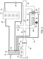
- Fig. 1 illustrates a configuration of an engine 1 particularly with a supercharger, to which an intake-air temperature controlling device according to this embodiment is applied (hereinafter, simply referred to as "the engine 1").
- the engine 1 is particularly a four-stroke engine which operates by a combustion chamber 17 repeating an intake stroke, a compression stroke, an expansion stroke, and an exhaust stroke.
- the engine 1 is particularly mounted on a vehicle (here, an automobile) with wheels, particularly four wheels. The vehicle is propelled by the engine 1.
- Fuel of the engine 1 is liquid fuel of which the main component is gasoline in this configuration example.
- the engine 1 is provided with an engine body 10 having a cylinder block 12 and a cylinder head 13 placed thereon.
- the engine body 10 is a multi-cylinder engine in which a plurality of cylinders 11 are formed inside the cylinder block 12. In Fig. 1 , only one cylinder 11 is illustrated. Other cylinders 11 of the engine body 10 are lined up in a direction perpendicular to the drawing sheet surface of Fig. 1 .
- a piston 3 is slidably inserted in each cylinder 11.
- the piston 3 is coupled to a crankshaft 15 through a connecting rod 14.
- the piston 3 defines the combustion chamber 17 together with the cylinder 11 and the cylinder head 13.
- the "combustion chamber” is not limited to a space thereof when the piston 3 is located at a compression top dead center. Therefore, the term “combustion chamber” may be used in a broader sense. That is, the “combustion chamber” may mean the space formed by the piston 3, the cylinder 11, and the cylinder head 13, regardless of the position of the piston 3.
- a water jacket 12a is formed in the perimeter of each cylinder 11 in the cylinder block 12.
- Engine coolant which cools the engine body 10 circulates inside the water jacket 12a. Although detailed illustration is omitted, after passing through the water jacket 12a, the engine coolant passes through a water jacket formed in the cylinder head 13, and flows out of the engine body 10.
- An intake port 18 is formed in the cylinder head 13 for every cylinder 11.
- the intake port 18 communicates with the combustion chamber 17.
- An intake valve 21 is disposed in the intake port 18.
- the intake valve 21 opens and closes an intake passage between the combustion chamber 17 and the intake port 18.
- the intake valve 21 is opened and closed at a given timing by a valve operating mechanism.
- the valve operating mechanism may be a variable valve operating mechanism which varies a valve timing and/or a valve lift.
- the variable valve operating mechanism particularly has an intake electric S-VT (Sequential-Valve Timing) 23 (refer to Fig. 4 ).
- the intake electric S-VT 23 is configured to continuously change a rotation phase of an intake cam shaft within a given angle range. Therefore, an open timing and a close timing of the intake valve 21 are continuously changed.
- the intake valve operating mechanism may have a hydraulic S-VT, instead of the electric S-VT.
- An exhaust port 19 is formed in the cylinder head 13 for every cylinder 11.
- the exhaust port 19 communicates with the combustion chamber 17.
- An exhaust valve 22 is disposed in the exhaust port 19.
- the exhaust valve 22 opens and closes an exhaust passage between the combustion chamber 17 and the exhaust port 19.
- the valve operating mechanism By the valve operating mechanism, the exhaust valve 22 is opened and closed at a given timing.
- This valve operating mechanism may be a variable valve operating mechanism which varies a valve timing and/or a valve lift.
- the variable valve operating mechanism particularly has an exhaust electric S-VT 24 (refer to Fig. 4 ).
- the exhaust electric S-VT 24 is configured to continuously change a rotation phase of an exhaust cam shaft within a given angle range. Thus, an open timing and a close timing of the exhaust valve 22 are changed continuously.
- the exhaust valve operating mechanism may have a hydraulic S-VT, instead of the electric S-VT.
- An injector 6 which directly injects fuel into the cylinder 11 is attached to the cylinder head 13 for every cylinder 11.
- the injector 6 is disposed so that its nozzle holes face the combustion chamber 17 from a center part of a ceiling surface of the combustion chamber 17 (in detail, a part slightly at the exhaust side from the center).
- the injector 6 directly injects an amount of fuel according to the operating state of the engine body 10 into the combustion chamber 17 at an injection timing set according to the operating state of the engine body 10.
- An ignition plug 25 is attached to the cylinder head 13 for every cylinder 11.
- the ignition plug 25 forcibly ignites a mixture gas inside the combustion chamber 17.
- the ignition plug 25 is disposed at the intake side. Electrodes of the ignition plug 25 face the inside of the combustion chamber 17, and are located near the ceiling surface of the combustion chamber 17. Note that the ignition plug 25 may be disposed at the exhaust side.
- the injector 6 may be disposed at the intake side or the exhaust side of the center axis of the cylinder 11.
- the geometric compression ratio of the engine body 10 is particularly set as 13:1 or more and 30:1 or less.
- SPCCI Park Controlled Compression Ignition
- SI Spark Ignition
- CI Compression Ignition
- SPCCI combustion controls CI combustion by utilizing generation of heat and a pressure buildup by SI combustion.
- the geometric compression ratio of the engine 1 may be set as 14 to 17 in a regular gasoline specification (the octane number of fuel is about 91), and may also be set as 15 to 18 in a high-octane specification (the octane number of fuel is about 96).
- An intake passage 40 is connected to one side of the engine body 10.
- the intake passage 40 communicates with the intake port 18 of each cylinder 11.
- the intake passage 40 is a passage through which intake air introduced into the combustion chamber 17 circulates.
- the intake passage 40 according to this embodiment has a first air intake part 141 which takes air at a relatively low temperature into the intake passage 40 as fresh air, and a second air intake part 142 which takes air at a relatively high temperature into the intake passage 40 as fresh air.
- the first air intake part 141 takes the fresh air at the same temperature as the ambient temperature into the intake passage 40
- the second air intake part 142 takes in the fresh air at a temperature higher than the ambient temperature into the intake passage 40.
- the configurations of the air intake parts 141 and 142 will be described later.
- An air cleaner 41 which filters the fresh air is disposed in the intake passage 40 at a part immediately downstream of the air intake parts 141 and 142.
- a surge tank 42 is disposed near the downstream end of the intake passage 40.
- a part of the intake passage 40 downstream of the surge tank 42 constitutes independent passages branched for every cylinder 11. The downstream end of the independent passage is connected to the intake port 18 of each cylinder 11.
- a throttle valve 43 is disposed between the air cleaner 41 and the surge tank 42 in the intake passage 40.
- the throttle valve 43 varies an opening of a valve to adjust an amount of fresh air introduced into the combustion chamber 17.
- the supercharger 44 boosts intake air introduced into the combustion chamber 17.
- the supercharger 44 is particularly a supercharger which is driven by the engine body 10.
- the supercharger 44 may be a Lysholm type, for example.
- the configuration of the supercharger 44 is not limited in particular.
- the supercharger 44 may also be a root type, a vane type, or a centrifugal type.
- An electromagnetic clutch 45 is particularly provided between the supercharger 44 and the engine body 10.
- the electromagnetic clutch 45 transmits a driving force from the engine body 10 to the supercharger 44, or intercepts the transmission of the driving force between the supercharger 44 and the engine body 10.
- an ECU (Electronic Control Unit) 100 particularly switches the disconnection (interception) and the connection (transmission) of the electromagnetic clutch 45 to switch the supercharger 44 between a driving state and a non-driving state. That is, the electromagnetic clutch 45 is a clutch which switches the driving and the non-driving of the supercharger 44.
- the engine 1 is configured to switch between the supercharger 44 boosting intake air introduced into the combustion chamber 17 and the supercharger 44 not boosting intake air introduced into the combustion chamber 17.
- An intercooler 46 is particularly disposed immediately downstream of the supercharger 44 in the supercharging side passage 40a.
- the intercooler 46 cools intake air compressed by the supercharger 44.
- the intercooler 46 is of a fluid-cooling type, and intercooler coolant circulates therethrough.
- the intercooler coolant is coolant different from the engine coolant.
- a bypass passage 47 is particularly connected to the intake passage 40.
- the bypass passage 47 connects a part of the intake passage 40 upstream of the supercharger 44 to a part downstream of the intercooler 46 so as to bypass the supercharger 44 and the intercooler 46.
- An air bypass valve 48 which opens and closes the bypass passage 47 is disposed in the bypass passage 47.
- the air bypass valve 48 is an on-off valve.
- the air bypass valve 48 When the supercharger 44 is not driven (i.e., when the electromagnetic clutch 45 is disconnected), the air bypass valve 48 is made into an open state (ON state). Therefore, gas which flows through the intake passage 40 bypasses the supercharger 44, and is introduced into the combustion chamber 17 of the engine 1.
- the engine 1 is operated in a non-boosted state (i.e., a natural aspirated state).
- the air bypass valve 48 may be comprised of a valve which can continuously vary the valve opening.
- An exhaust passage 50 is connected to the other side of the engine body 10.
- the exhaust passage 50 communicates with the exhaust port 19 of each cylinder 11.
- the exhaust passage 50 is a passage through which exhaust gas discharged from the combustion chamber 17 circulates. Although detailed illustration of an upstream part of the exhaust passage 50 is omitted, it constitutes independent passages branched for every cylinder 11. The upstream end of the independent passage is connected to the exhaust port 19 of each cylinder 11.
- An exhaust gas purification system having a plurality of catalytic converters is disposed in the exhaust passage 50.
- the upstream catalytic converter has a three-way catalyst 511 and a GPF (Gasoline Particulate Filter) 512.
- a downstream catalytic converter is disposed outside the engine bay.
- the downstream catalytic converter has a three-way catalyst 513.
- the exhaust gas purification system is not limited to the illustrated configuration.
- the GPF may be omitted.
- the catalytic converter is not limited to those having the three-way catalyst.
- the disposed order of the three-way catalyst and the GPF may be change suitably.
- An EGR passage 52 which constitutes an external EGR system is particularly connected between the intake passage 40 and the exhaust passage 50.
- the EGR passage 52 is a passage which recirculates a portion of exhaust gas to the intake passage 40.
- the upstream end of the EGR passage 52 is connected to the exhaust passage 50 between the upstream catalytic converter and the downstream catalytic converter.
- the downstream end of the EGR passage 52 is connected to the intake passage 40 at a location upstream of the supercharger 44.
- Exhaust gas which flows through the EGR passage 52 (hereinafter, referred to as the "EGR gas”) enters into the intake passage 40 upstream of the supercharger 44, without passing through the air bypass valve 48 of the bypass passage 47, when introduced into the intake passage 40.
- An EGR cooler 53 of a fluid cooling type is disposed in the EGR passage 52.
- the EGR cooler 53 cools the EGR gas passing through the EGR passage 52.
- An EGR valve 54 is disposed in the EGR passage 52.
- the EGR valve 54 is configured to adjust a flow rate of the EGR gas which flows through the EGR passage 52. By varying the opening of the EGR valve 54, a recirculating amount of the cooled EGR gas can be adjusted.
- the EGR valve 54 may be comprised of an on-off valve, or may be comprised of a valve which can continuously vary the valve opening.
- the cooling system of the engine 1 particularly includes a first cooling path 60 which cools the engine body 10 by circulating the engine coolant in the engine body 10, and a second cooling path 70 which cools intake air after passing through the supercharger 44 by circulating the intercooler coolant in the intercooler 46.
- the first cooling path 60 is particularly provided with a first pump 61, a first radiator 62 configured to cool the engine coolant which flows through the first cooling path 60, and a flow rate control valve 63 which adjusts a flow rate of the engine coolant circulating through the first cooling path 60.
- the first pump 61 is particularly a mechanical pump which is driven by the crankshaft 15 of the engine body 10 in an interlocked manner.
- a discharge port of the first pump 61 is connected to the water jacket 12a of the engine body 10.
- the first radiator 62 particularly cools the engine coolant which passes through the water jacket of the engine body 10 and is discharged from the cylinder head 13.
- the first radiator 62 cools the engine coolant by outside air when a vehicle to which the engine 1 is mounted travels forward.
- the flow rate control valve 63 is particularly disposed at an intermediate location of a path through which the engine coolant which is discharged from the first radiator 62 and flows into the first pump 61 passes. That is, the flow rate control valve 63 is disposed at the entrance side into the engine body 10 in the first cooling path 60.
- the flow rate control valve 63 is comprised of an electric thermostat valve.
- the flow rate control valve 63 is a valve in which a heating wire is built into the thermostat valve. Fundamentally, when the temperature of the engine coolant is above a preset fluid temperature setting, the flow rate control valve 63 is configured to open according to the temperature. However, by applying electric current to the heating wire, it can open even when the temperature of the engine coolant is below the fluid temperature setting.
- Fig. 3 illustrates one example of a characteristic of the flow rate control valve 63 to the temperature of the engine coolant.
- the temperature of the engine coolant illustrated on the horizontal axis is the temperature at the location of the flow rate control valve 63, and it differs from the temperature of the engine coolant which flows into the first radiator 62.
- the flow rate control valve 63 begins to open when the temperature of the engine coolant is particularly about 95°C to about 96°C. On the other hand, during the power is supplied, it can open even if the temperature of the engine coolant is below about 95°C. As illustrated in Fig. 3 , the temperature at which the flow rate control valve 63 begins to open is lowered as the current supplied to the heating wire increases. Moreover, the opening of the flow rate control valve 63 while the temperature is constant can be increased as the current supplied to the heating wire increases, within a range of the opening of the flow rate control valve 63 being smaller than a fully opened state. Note that in this embodiment, the fluid temperature setting is particularly set as about 95°C to about 97°C. Moreover, the flow rate control valve 63 may be an electromagnetic valve, such as a solenoid valve, instead of the thermostat valve.
- the power supplied to the flow rate control valve 63 is adjusted based on the operating state of the engine body 10, the ambient temperature, etc. so that the temperature of the engine coolant becomes a suitable temperature.
- the first cooling path 60 also passes through the EGR cooler 53. That is, the EGR gas passing through the EGR passage 52 is cooled by heat exchange with the engine coolant.
- the second cooling path 70 is particularly provided with a second pump 71, and a second radiator 72 which cools the intercooler coolant which flows through the second cooling path 70.
- the second pump 71 is particularly an electric pump driven by electric power.
- the second pump 71 is configured to increase a discharging amount of the intercooler coolant as the supplied electric power increases.
- the second radiator 72 particularly cools the intercooler coolant discharged from the intercooler 46.
- the second radiator 72 is particularly disposed below and adjacent to the first radiator 62.
- the second radiator 72 cools the intercooler coolant by outside air when the vehicle to which the engine 1 is mounted travels forward.
- the intercooler coolant cooled by the second radiator 72 flows into the second pump 71.
- the cooling system of the engine 1 particularly includes a grille shutter 81 and a radiator fan 82, as a mechanism to send the outside air to the first and second radiators 62 and 72.
- the grille shutter 81 is particularly provided to a location of the vehicle forward of the first and second radiators 62 and 72.
- the grille shutter 81 particularly adjusts a flow rate of air taken in into the engine bay where the engine 1 is disposed.
- the grille shutter 81 is particularly comprised of a plurality of flappers 81a which rotate on respective axes extending in the vehicle width direction. The grille shutter 81 is fully opened when the flappers 81a become perpendicular to the vertical direction, and is fully closed when the flappers 81a become substantially parallel to the vertical direction.
- a flow rate of the air taken in into the engine bay i.e., an amount of the outside air which flows to the first and second radiators 62 and 72, is adjusted by the angle of the flappers 81a with respect to the vertical direction.
- the angle of the flappers 81a with respect to the vertical direction i.e., an opening of the grille shutter 81
- the term "vertical direction” as used herein refers to the up-and-down direction of the vehicle 1 and normally corresponds to a direction perpendicular to a road surface.
- the grille shutter 81 constitutes a part of an intake air temperature adjuster and a fluid temperature adjuster. Note that "forward" and “rearward” in the vehicle mean the directions when the vehicle is oriented normally.
- the radiator fan 82 is particularly provided rearward of the first and second radiators 62 and 72 and forward of the second air intake part 142.
- the radiator fan 82 draws the outside air into the engine bay by rotating to assist the outside air to flow through the first and second radiators 62 and 72.
- the radiator fan 82 is particularly configured to increase a drawing amount of the outside air as its rotational speed increases.
- the radiator fan 82 is configured to be electrically adjustable of the rotational speed.
- the radiator fan 82 constitutes a part of the intake air temperature adjuster and the fluid temperature adjuster.
- the outside air taken in through the grille shutter 81 particularly cools the coolant which flows through the first and second radiators 62 and 72 by heat exchange with the coolant.
- the outside air which passed through the first and second radiators 62 and 72 flows rearward of the radiator fan 82.
- the intake passage 40 particularly has the two air intake parts comprised of the first and second air intake parts 141 and 142.
- the first air intake part 141 is particularly located in front of or forward of the radiators 62 and 72, in more detail, forward of the grille shutter 81.
- the first air intake part 141 takes in the outside air (air not heated) to the intake passage 40.
- the second air intake part 142 is located behind or rearward of the radiators 62 and 72, in more detail, rearward of the radiator fan 82.
- the second air intake part 142 takes in air (outside air), which passes through the first and second radiators 62 and 72 and flows rearward of the radiator fan 82, to the intake passage 40.
- the second air intake part 142 takes in air, after heat exchange with the coolant which flows through the first and second radiators 62 and 72, to the intake passage 40.
- the second air intake part 142 takes in air, at a temperature higher than the ambient temperature, to the intake passage 40.
- the first and second air intake parts 141 and 142 is particularly provided with an intake air adjusting valve 143 which adjusts a ratio of the amount of air taken in through the first air intake part 141 to the intake passage 40 and the amount of air taken in through the second air intake part 142 to the intake passage 40.
- a valve of the intake air adjusting valve 143 is particularly disposed at each of the first and second air intake parts 141 and 142, and the valves operate in an interlocked manner. In detail, the opening of the valve of the second air intake part 142 becomes smaller as the opening of the valve of first air intake part 141 becomes larger.
- the intake air adjusting valve 143 constitutes a part of the intake air temperature adjuster.
- the intake air adjusting valve 143 changes the opening of each valve in the interlocked manner by coupling the valves through the common axis.
- the intake air adjusting valve 143 provided to the first air intake part 141 and the intake air adjusting valve 143 provided to the second air intake part 142 may be configured to be adjustable of the valve openings independently.
- the engine 1 is provided with the ECU (Electronic Control Unit or Engine Control Unit) 100 for operating the engine 1.
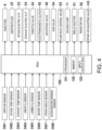
- the ECU 100 is a controller based on a well-known microcomputer, and as illustrated in Fig. 4 , includes a processor (e.g., a central processing unit (CPU)) 101 which executes a program, memory 102 which is comprised of RAM (Random Access Memory) and/or ROM (Read Only Memory) for example, and stores the programs and data, and an input/output bus 103 which inputs and outputs an electrical signal.
- the ECU 100 is one example of the controller.
- the ECU 100 is particularly connected to various kinds of one or more sensors SW1-SW8.
- the sensors SW1-SW8 each output a detection signal to the ECU 100.
- the sensors include the following sensors.
- an airflow sensor SW1 which is disposed downstream of the air cleaner 41 in the intake passage 40 and detects a flow rate of fresh air flowing through the intake passage 40
- an intake temperature sensor SW2 which is attached to the surge tank 42 and detects the temperature of intake air supplied to the combustion chamber 17
- an exhaust temperature sensor SW3 which is disposed at the exhaust passage 50 and detects the temperature of exhaust gas discharged from the combustion chamber 17
- a linear O 2 sensor SW4 which is disposed upstream of the upstream catalytic converter in the exhaust passage 50 and detects an oxygen concentration in the exhaust gas
- a lambda ( ⁇ ) O 2 sensor SW5 which is disposed downstream of the three-way catalyst 511 in the upstream catalytic converter and detects an oxygen concentration in the exhaust gas
- a fluid temperature sensor SW6 which is attached to the cylinder head 13 of the engine body 10 and detects the temperature of the engine coolant
- a crank angle sensor SW7 which is attached to the engine body 10 and detects a rotation angle of the crankshaft 15
- the ECU 100 determines the operating state of the engine body 10 and calculates a controlled amount (parameter) of each device based on these detection signals.
- the ECU 100 outputs a control signal according to the calculated controlled amount to each of the injector 6, the ignition plug 25, the intake electric S-VT 23, the exhaust electric S-VT 24, the throttle valve 43, the electromagnetic clutch 45 of the supercharger 44, the air bypass valve 48, the EGR valve 54, the flow rate control valve 63, the second pump 71, the grille shutter 81, the radiator fan 82, and the intake air adjusting valve 143.
- the ECU 100 calculates an engine speed of the engine body 10 based on the detection signal of the crank angle sensor SW7.
- the ECU 100 calculates an engine load of the engine body 10 based on the detection signal of the accelerator opening sensor SW8.
- the ECU 100 sets a target EGR rate (i.e., a ratio of the EGR gas to the entire gas inside the combustion chamber 17) based on the operating state of the engine body 10 (mainly, the engine load and the engine speed) and a preset map. Then, the ECU 100 determines a target EGR amount based on the target EGR rate and an intake air amount based on the detection signal of the accelerator opening sensor SW8. Moreover, by adjusting the opening of the EGR valve 54, the ECU 100 performs a feedback control so that the external EGR amount introduced into the combustion chamber 17 becomes the target EGR amount.
- a target EGR rate i.e., a ratio of the EGR gas to the entire gas inside the combustion chamber 17
- the ECU 100 particularly performs an air-fuel ratio feedback control when a given control condition is satisfied. Specifically, based on the oxygen concentrations in the exhaust gas detected by the linear O 2 sensor SW4 and the lambda Oz sensor SW5, the ECU 100 adjusts a fuel injection amount of the injector 6 so that the air-fuel ratio of the mixture gas becomes a desired value.
- Fig. 5 particularly illustrates an operating range map of the engine 1 when the engine 1 is warm (i.e., after a warm-up of the engine body 10).
- the operating range map of the engine 1 is particularly defined by the engine load and speed, and is divided into two more, particularly three ranges depending on the engine load and speed.
- the three ranges are comprised of a range A where an idle operation is included, the engine speed is low below a given engine speed Ne, and the engine load is low below a given load Tq, a range B where the engine speed is high above the given engine speed Ne, and the engine load is below the given load Tq, and a range C where the engine load is the given load Tq or above.
- the given engine speed Ne may be about 3500 rpm, for example.
- the phrase "after the warm-up of the engine body 10" as used herein refers to a state where the temperature of the engine coolant detected by the fluid temperature sensor SW6 is about 80°C or more, and the temperature of the intake air detected by the intake temperature sensor SW2 is about 25°C or more.
- the engine 1 performs SPCCI combustion which is the combination of SI combustion and CI combustion in all the ranges A-C in order to mainly improve combustion stability and fuel efficiency.
- SPCCI combustion is the combination of SI combustion and CI combustion in all the ranges A-C in order to mainly improve combustion stability and fuel efficiency.
- the ECU 100 controls the temperature of intake air introduced into the engine body 10 by using the cooling system of the engine 1. Below, operation of the engine 1 in each range is described in detail with reference to Figs. 6 to 9 .
- the engine 1 While the engine body 10 operates in the range A, the engine 1 performs SPCCI combustion in a state where an air-fuel ratio (A/F) or a gas-fuel ratio (G/F) of the mixture gas inside the cylinder 11 (combustion chamber 17) is larger than a stoichiometric air-fuel ratio.
- A/F air-fuel ratio
- G/F gas-fuel ratio
- fuel is injected from the injector 6 so that A/F or G/F becomes about 25:1 or more, and the ignition plug 25 is operated at a desired timing.
- the range A particularly corresponds to a lean operating range where the air-fuel ratio (A/F) of the mixture gas formed inside the cylinder 11, or the gas-fuel ratio (G/F) which is a relationship between the total gas weight G inside the cylinder 11 and the weight F of fuel fed to the cylinder 11 is relatively high.
- the lean operating range is not limited to the low-load low-speed range A.
- the lean operating range may be in high-load and/or high-speed range.
- SPCCI combustion especially, CI combustion
- the ECU 100 controls and operates each device so that intake air at or above a first intake air temperature Ta1 is introduced into the engine body 10.
- the first intake air temperature Ta1 is about 80°C, for example.
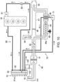
- the ECU 100 when the operating state of the engine body 10 is in the range A, as illustrated in Fig. 6 , the ECU 100 outputs the control signal to the intake air adjusting valve 143 so that the first air intake part 141 particularly becomes fully closed and the second air intake part 142 becomes fully opened. Moreover, the ECU 100 particularly outputs control signals to the electromagnetic clutch 45 and the air bypass valve 48 to disconnect the electromagnetic clutch 45 and fully open the air bypass valve 48 so that the supercharger 44 is not driven and the bypass passage 47 is opened. Moreover, the ECU 100 particularly turns off the power to the flow rate control valve 63 so that hot engine coolant flows into the first radiator 62.
- the ECU 100 adjusts the opening of the grille shutter 81 and the rotational speed of the radiator fan 82 so that intake air at the first intake air temperature Ta1 or higher is taken in through the second air intake part 142. Moreover, the ECU 100 fully closes the EGR valve 54.
- the flow rate control valve 63 When the power to the flow rate control valve 63 is turned off, the flow rate control valve 63 will not be opened until the engine coolant becomes above the fluid temperature setting. Thus, in the state where the engine coolant is below the fluid temperature setting, the engine coolant is heated by the heat of the engine body 10 without circulating. When the engine coolant becomes above the fluid temperature setting, the flow rate control valve 63 begins to open and the engine coolant begins to circulate through the first cooling path 60. Therefore, the hot engine coolant above the fluid temperature setting flows into the first radiator 62. The engine coolant which flows into the first radiator 62 is the engine coolant after passing through the flow rate control valve 63 and being heated by the engine body 10.
- the temperature of the engine coolant which flows into the first radiator 62 (corresponding to the temperature detected by the fluid temperature sensor SW6) is higher than the preset temperature. Therefore, the flow rate control valve 63 constitutes a part of the fluid temperature adjuster. Note that when the operating state of the engine body 10 is in the range A, the opening of the flow rate control valve 63 varies within a range where the temperature of the engine coolant at the location of the flow rate control valve 63 falls within "range A" of the graph in Fig. 3 .
- the ECU 100 particularly controls operations of the grille shutter 81 and the radiator fan 82 so that the detection result of the fluid temperature sensor SW6 becomes a first fluid temperature Tw1.
- the ECU 100 fully closes the opening of the grille shutter 81 and sets the rotational speed of the radiator fan 82 to 0 (i.e., the radiator fan 82 is not driven). Therefore, when the engine coolant is below the first fluid temperature Tw1, the engine coolant is not cooled much and the fluid temperature increases.
- the ECU 100 opens the grille shutter 81 and increases the rotational speed of the radiator fan 82.
- the hot outside air i.e., intake air (fresh air) at or above the first intake air temperature Ta1 is taken into the intake passage 40 through the second air intake part 142.
- the first fluid temperature Tw1 is a temperature higher than the fluid temperature setting (for example, about 105°C).
- the ECU 100 particularly adjusts the opening of the grille shutter 81 within a small opening range, in order to keep the temperature of the engine coolant at or above the first fluid temperature Tw1 as much as possible.
- the ECU 100 adjusts the opening of the grille shutter 81 so that the angle at the acute angle side of the flappers 81a with respect to the vertical direction falls within a range below about 30°.
- the ECU 100 makes the rotational speed of the radiator fan 82 the lowest possible, in order to keep the temperature of the engine coolant at or above the first fluid temperature Tw1 as much as possible.
- the flow rate of air passing through the first radiator 62 is reduced by adjusting the opening of the grille shutter 81 at the small opening range, and making the rotational speed of the radiator fan 82 low. Therefore, the air passing through the first radiator 62 is uniformly heated by heat exchange with the engine coolant circulating the first radiator 62. As a result, the temperature of air taken in through the second air intake part 142 to the intake passage 40 can be made as high as possible.
- the hot intake air taken in through the second air intake part 142 passes through the bypass passage 47 and flows into the surge tank 42. Then, the hot intake air is introduced into the combustion chamber 17 of the engine body 10.
- Fig. 7 is a flowchart illustrating a processing operation of the ECU 100 when the operating state of the engine body 10 is in the range A.
- Fig. 8 is a time chart illustrating one example of driving states of various devices when the operating state of the engine body 10 is in the range A.
- the intake air adjusting valve 143 is adjusted so that the second air intake part 142 is fully opened (refer to Fig. 8 ), and the power supplied to the flow rate control valve 63 is turned off (refer to Fig. 8 ).
- Step S1 the ECU 100 particularly reads information from the sensors SW1-SW8.
- the ECU 100 particularly determines whether the temperature of the engine coolant detected by the fluid temperature sensor SW6 is below the first fluid temperature. If YES (if the temperature of the engine coolant is below the first fluid temperature Tw1) the ECU 100 shifts to Step S3, and on the other hand, if NO (if the temperature of the engine coolant is above the first fluid temperature Tw1, it shifts to Step S4.
- Step S3 particularly the ECU 100 fully closes the grille shutter 81 and sets the rotational speed of the radiator fan 82 to 0.
- the engine coolant circulating the first radiator 62 is no longer cooled, and, as illustrated in Fig. 8 , the temperature of the engine coolant increases.
- the ECU 100 particularly increases the opening of the grille shutter 81 and increases the rotational speed of the radiator fan 82.
- the engine coolant circulating the first radiator 62 is cooled, and, as illustrated in Fig. 8 , the temperature of the engine coolant decreases.
- the ECU 100 may increase the opening of the grille shutter 81 as the engine load increases, or may increase the rotational speed of the radiator fan 82 as the engine load increases.
- the ECU 100 particularly outputs control signals to the grille shutter 81 and the radiator fan 82 so that the temperature detected by the fluid temperature sensor SW6 becomes the first fluid temperature Tw1. Therefore, the intake air at or above the first intake air temperature Ta1 is stably introduced into the engine body 10.
- the hot intake air (at or above the first intake air temperature Ta1) is introduced into the engine body 10. Therefore, SPCCI combustion can be stably performed when the engine body 10 operates in the range A.
- the ECU 100 outputs the control signal to the second pump 71 so that the intercooler coolant is supplied to the intercooler 46. This is for the cooling of the intake air by the intercooler 46 being carried out with a sufficient response, when the operating state of the engine body 10 becomes in a range (for example, the range C) where the supercharger 44 is driven, from the range A.
- the ECU 100 outputs the control signal to the second pump 71 so that the flow rate of the intercooler coolant supplied per unit time to the intercooler 46 becomes a first flow rate.
- the engine 1 While the engine body 10 operates in the range B, the engine 1 performs SPCCI combustion in the state where A/F or G/F of the mixture gas inside the cylinder 11 (combustion chamber 17) becomes about or near the stoichiometric air-fuel ratio.
- fuel is injected from the injector 6 so that A/F or G/F becomes about 14.5:1 to about 15.0:1, and the ignition plug 25 is operated at a desired timing.
- the range B corresponds to a richer operating range where A/F or G/F is relatively low.
- the richer operating range is not limited to the low-load high-speed range B.
- the richer operating range may be in high-load and/or low-speed range.
- the ECU 100 controls and operates each device so that intake air at or above the first intake air temperature Ta1 is introduced into the engine body 10.
- the ECU 100 when the operating state of the engine body 10 is in the range B, as illustrated in Fig. 9 , the ECU 100 particularly outputs the control signal to the intake air adjusting valve 143 so that the first air intake part 141 is fully closed and the second air intake part 142 is fully opened. Moreover, the ECU 100 particularly outputs control signals to the electromagnetic clutch 45 and the air bypass valve 48 to connect the electromagnetic clutch 45 and fully open the air bypass valve 48 so that the supercharger 44 is driven and the bypass passage 47 is opened. Moreover, the ECU 100 particularly turns on the power to the flow rate control valve 63.
- the ECU 100 particularly adjusts the opening of the grille shutter 81 and the rotational speed of the radiator fan 82 so that intake air at or above the first intake air temperature Ta1 is taken in through the second air intake part 142. Moreover, the ECU 100 particularly opens the EGR valve 54 to introduce the EGR gas.
- the flow rate control valve 63 When turning on the power to the flow rate control valve 63, the flow rate control valve 63 opens, even if the engine coolant is below the fluid temperature setting. Thus, even if the engine coolant is below the fluid temperature setting, the engine coolant circulates through the first cooling path 60. Therefore, the engine coolant below the first fluid temperature Tw1 flows into the first radiator 62. Note that when the operating state of the engine body 10 is in the range B, the opening of the flow rate control valve 63 varies within a range where the temperature of the engine coolant at the location of the flow rate control valve 63 falls within "range B" of the graph in Fig. 3 .
- the ECU 100 While the operating state of the engine body 10 is in the range B, the ECU 100 particularly opens the grille shutter 81 and drives the radiator fan 82, even if the detection result of the fluid temperature sensor SW6 is below the first fluid temperature Tw1.
- the ECU 100 adjusts the opening of the grille shutter 81 and the rotational speed of the radiator fan 82 so that the detection result of the fluid temperature sensor SW6 becomes below the first fluid temperature Tw1 and above a second fluid temperature Tw2.
- the ECU 100 particularly increases the opening of the grille shutter 81 and increases the rotational speed of the radiator fan 82 (refer to Fig. 11 ), as compared with the opening when the operating state of the engine body 10 is in the range A.
- the ECU 100 adjusts the opening of the grille shutter 81 within a middle opening range.
- ECU 100 adjusts the angle at the acute angle side of the flappers 81a with respect to the vertical direction within a range of about 30° or more and below 60°.
- the second fluid temperature Tw2 is a temperature lower than the first fluid temperature Tw1 (for example, about 90°C).
- the intake air during the recirculation is compressed by the supercharger 44, its temperature increases. Moreover, when the operating state of the engine body 10 is in the range B, since the EGR valve 54 is opened, the EGR gas is taken into the recirculating intake air. Since the EGR gas is higher in the temperature than the intake air taken into the intake passage 40 through the second air intake part 142, the temperature of the intake air into which the EGR gas is taken in increases.
- the ECU 100 In order to prevent the recirculating intake air (fresh air + EGR gas) from becoming excessively high in temperature, the ECU 100 particularly outputs the control signal to the second pump 71 so that the intercooler coolant may be supplied to the intercooler 46. Therefore, the recirculating intake air is cooled by the intercooler 46. At this time, the ECU 100 outputs the control signal to the second pump 71 so that a flow rate of the intercooler coolant supplied per unit time to the intercooler 46 becomes a second flow rate.
- the second flow rate is more than the first flow rate, and is such a flow rate that the temperature of the recirculating intake air does not become below the first intake air temperature Ta1.
- the intake air is heated by the recirculating of intake air and the introduction of EGR gas.
- the intake air at or above the first intake air temperature Ta1 can be introduced into the combustion chamber 17 of the engine body 10, even if the temperature of air taken in to the intake passage 40 from the second air intake part 142 is low. Therefore, SPCCI combustion can be stably performed, while the engine body 10 operates in the range B.
- the engine body 10 operates in the range C, as for the engine 1, A/F or G/F of the mixture gas inside the combustion chamber 17 performs SPCCI combustion in the state about or near a stoichiometric air-fuel ratio.
- fuel is injected from the injector 6 so that A/F or G/F becomes about 14.5:1 to about 15.0:1, and the ignition plug 25 is operated at a desired timing.
- the range C corresponds to a richer operating range where A/F or G/F is relatively low.
- the richer operating range is not limited to the high-load range C.
- the richer operating range may be in low-load and/or low-speed range.
- the ECU 100 when the operating state of the engine body 10 is in the range C, as illustrated in Fig. 10 , the ECU 100 particularly outputs the control signal to the intake air adjusting valve 143 so that the first air intake part 141 is fully opened and the second air intake part 142 is fully closed. Moreover, the ECU 100 particularly outputs the control signals to the electromagnetic clutch 45 and the air bypass valve 48 to connect the electromagnetic clutch 45 and fully close the air bypass valve 48 so that the supercharger 44 is driven and the bypass passage 47 is closed. Moreover, the ECU 100 turns on the power to the flow rate control valve 63. Moreover, the ECU 100 particularly adjusts the opening of the grille shutter 81 and the rotational speed of the radiator fan 82 so that the engine coolant and the intercooler coolant are cooled. Moreover, the ECU 100 particularly opens the EGR valve 54 to introduce the EGR gas.
- the flow rate control valve 63 opens, even if the engine coolant is below the fluid temperature setting.
- the engine coolant circulates through the first cooling path 60. Therefore, the engine coolant below the fluid temperature setting flows into the first radiator 62.
- the opening of the flow rate control valve 63 varies within a range where the temperature of the engine coolant at the location of the flow rate control valve 63 falls within "range C" of the graph in Fig. 3 .
- the ECU 100 When the operating state of the engine body 10 is in the range C, the ECU 100 particularly opens the grille shutter 81 and drives the radiator fan 82. At this time, the ECU 100 adjusts the opening of the grille shutter 81 and the rotational speed of the radiator fan 82 so that the detection result of the fluid temperature sensor SW6 becomes the second fluid temperature Tw2. In detail, the ECU 100 particularly adjusts the opening of the grille shutter 81 within a high opening range, i.e., a range where the angle at the acute angle side of the flappers 81a with respect to the vertical direction (including a right angle) becomes about 60° or more and about 90° or less.
- a high opening range i.e., a range where the angle at the acute angle side of the flappers 81a with respect to the vertical direction (including a right angle) becomes about 60° or more and about 90° or less.
- the ECU 100 makes the rotational speed of the radiator fan 82 higher than the rotational speed when the operating state of the engine body 10 is in the ranges A and B. Accordingly, as compared with the cases where the operating state of the engine body 10 is in the ranges A and B (i.e., when the engine load is low), the amount of the outside air which flows to the first and second radiators 62 and 72 increases. Therefore, the coolant which flows through the first and second radiators 62 and 72 can be actively cooled, and the engine body 10 can be cooled appropriately.
- intake air fresh air
- the intake passage 40 is taken into the intake passage 40 through the first air intake part 141.
- EGR valve 54 since the EGR valve 54 is opened, EGR gas is taken into the intake air which is taken into the intake passage 40 through the first air intake part 141.
- the air bypass valve 48 since the air bypass valve 48 is fully closed, the intake air (fresh air + EGR gas) flows toward the supercharging side passage 40a. Since the electromagnetic clutch 45 is connected and the supercharger 44 is driven, the intake air which flowed toward the supercharging side passage 40a is boosted by the supercharger 44. Therefore, the temperature of the intake air increases.
- the ECU 100 outputs the control signal to the second pump 71 so that the intercooler coolant is supplied to the intercooler 46, in order to make the temperature of the intake air boosted by the supercharger 44 at or below the second intake air temperature Ta2.
- the ECU 100 outputs the control signal to the second pump 71 so that the flow rate of the intercooler coolant supplied per unit time to the intercooler 46 becomes a third flow rate.
- the third flow rate is more than the second flow rate.
- the temperature of the intake air can be made at or below the second intake air temperature Ta2 by increasing the flow rate of the intercooler coolant supplied to the intercooler 46.
- the temperature of the intercooler coolant is low as compared with the cases when the operating state of the engine body 10 is in the ranges A and B. Therefore, the temperature of intake air can be made at or below the second intake air temperature Ta2 more efficiently.
- the intake air which is boosted by the supercharger 44 and cooled at or below the second intake air temperature Ta2 by the intercooler 46 is supplied to the combustion chamber 17 of the engine body 10 through the surge tank 42.
- the cold intake air (at or below the second intake air temperature Ta2) is introduced into the engine body 10, and the engine body 10 is cooled appropriately. Therefore, while the engine body 10 operates in the range C, SPCCI combustion can be stably performed.
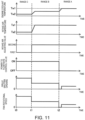
- Fig. 11 is particularly a time chart illustrating a change in the operating state of each device in accordance with a change in the operating state of the engine body 10.
- the scale of the vertical axis may differ from the time chart of Fig. 8 , such as the scale for the opening of the grille shutter 81.
- the intake air temperature is the detection result of the intake air temperature sensor SW2, and may differ from the temperature of air which is taken into the intake passage 40 from the first and second air intake parts 141 and 142.
- the ECU 100 controls and operates each device so that the temperature of the engine coolant becomes the second fluid temperature Tw2 and the intake air temperature becomes the second intake air temperature Ta2.
- the ECU 100 controls and operates each device so that the intake air temperature becomes the first intake air temperature Ta1, while the temperature of the engine coolant is below the first fluid temperature Tw1 and above the second fluid temperature Tw2.
- the ECU 100 reduces the opening of the grille shutter 81 and decreases the rotational speed of the radiator fan 82. Accordingly, the temperature of the engine coolant is made below the first fluid temperature Tw1 and above the second fluid temperature Tw2.
- the ECU 100 particularly operates the intake air adjusting valve 143 so that air can be taken in through the second air intake part 142.
- the temperature of the air taken in through the second air intake part 142 is above the second intake air temperature Ta2 but below the first intake air temperature Ta1.
- the ECU 100 connects the electromagnetic clutch 45 to drive the supercharger 44, and fully opens the air bypass valve 48 to recirculate a portion of the intake air inside the intake passage 40.
- the ECU 100 outputs the control signal to the second pump 71 so that the flow rate of the intercooler coolant supplied per unit time to the intercooler 46 decreases (from the third flow rate to the second flow rate). Accordingly, the ECU 100 sets the temperature of the intake air at the stage where it is introduced into the engine body 10 to the first intake air temperature Ta1.
- the ECU 100 operates and controls each device so that the temperature of the engine coolant becomes the first fluid temperature Tw1 and the intake air temperature becomes the first intake air temperature Ta1.
- the ECU 100 suspends the power to the flow rate control valve 63. Therefore, the flow rate control valve 63 will not open until the temperature of the engine coolant becomes the preset temperature or higher.
- the ECU 100 reduces the opening of the grille shutter 81 and reduces the rotational speed of the radiator fan 82. In detail, as illustrated in Fig.
- the ECU 100 fully closes the grille shutter 81 and sets the rotational speed of the radiator fan 82 to 0 until the detection result of the fluid temperature sensor SW6 becomes the first fluid temperature Tw1 or higher.
- the temperature of the engine coolant becomes the first fluid temperature Tw1.
- the ECU 100 opens the grille shutter 81 and increases the rotational speed of the radiator fan 82.
- the opening of the grille shutter 81 and the rotational speed of the radiator fan 82 at this time are less than that of when the operating state of the engine body 10 is in the range B. Therefore, when the operating state of the engine body 10 is in the range A, the flow rate of air passing through the first radiator 62 decreases, as compared with the cases when the operating state of the engine body 10 is in the ranges B and C.
- the ECU 100 disconnects the electromagnetic clutch 45 and does not drive the supercharger 44, and fully opens the air bypass valve 48 to introduce the intake air into the engine body 10 through the bypass passage 47.
- the ECU 100 when the engine body 10 is in the operating range where CI combustion is performed (ranges A-C), and the operating state of the engine body 10 is in the lean operating range (range A), the ECU 100 outputs the control signal to each device (the flow rate control valve 63, the grille shutter 81, the radiator fan 82, and the intake air adjusting valve 143) so that the temperature of air taken in through the air intake parts (the first and second air intake parts 141 and 142) to the intake passage 40 becomes high, as compared with the case when the operating state of the engine body 10 is in the richer operating range (ranges B and C). Therefore, when the operating state of the engine body is in the range A, the air at the temperature as high as possible can be taken into the intake passage 40.
- the air intake part includes the first air intake part 141 which is located forward of the first radiator 62, and the second air intake part 142 which is located rearward of the first radiator 62 and takes in air after passing through the first radiator 62 and exchanging heat with the engine coolant to the intake passage 40.
- the air intake part also includes the intake air adjusting valve 143 which adjusts the ratio of the amount of air taken in through the first air intake part 141 to the intake passage 40 to the amount of air taken in through the second air intake part 142 to the intake passage 40.
- the ECU 100 When the operating state of the engine body is in the range A, the ECU 100 outputs the control signal to the intake air adjusting valve 143 so that the ratio of the amount of air taken in through the second air intake part 142 to the intake passage 40 increases, as compared with the case when the operating state of the engine body 10 is in the range C.
- air when the operating state of the engine body is in the range A, air is fundamentally taken into the intake passage 40 only through the second air intake part 142. That is, the second air intake part 142 takes into the intake passage 40 the air heated by heat exchange with the engine coolant circulating the first radiator 62.
- the air at the temperature higher enough than the ambient temperature can be taken into the intake passage 40.
- the temperature of the mixture gas when a compression starts can be more effectively increased, thereby further improving combustion stability in the lean operating range.
- the ECU 100 when the operating state of the engine body 10 is in the range A, the ECU 100 outputs the control signal to each device (the flow rate control valve 63, the grille shutter 81, and the radiator fan 82) so that the temperature of the engine coolant circulating the first radiator 62 is increased, as compared with the cases when the operating state of the engine body 10 is in the ranges B and C. Therefore, the temperature of air taken into the intake passage 40 through the second air intake part 142 can be more efficiently increased. Therefore, when the operating state of the engine body is in the range A, the air at the temperature higher enough than the ambient temperature can be more efficiently taken into the intake passage 40. As a result, in the lean operating range within the operating range where CI combustion is performed, the temperature of the mixture gas when a compression starts can be increased further effectively, thereby further improving combustion stability in the lean operating range.
- the ECU 100 when the operating state of the engine body 10 is in the range A, the ECU 100 outputs the control signals to the grille shutter 81 and the radiator fan 82 so that at least one of the opening of the grille shutter 81 and the rotational speed of the radiator fan 82 is reduced, as compared with the cases when the operating state of the engine body 10 is in the ranges B and C. That is, when the opening of the grille shutter 81 is reduced and the rotational speed of the radiator fan 82 is reduced, the flow rate of air passing through the first radiator 62 decreases. When the flow rate of air passing through the first radiator 62 decreases, air passing through the first radiator 62 is uniformly heated by heat exchange with the engine coolant circulating the first radiator 62.
- the temperature of air taken into the intake passage 40 through the second air intake part 142 can be increased further efficiently. Therefore, in the lean operating range within the operating range where CI combustion is performed, the temperature of the mixture gas when a compression starts can be increased further effectively, thereby further improving combustion stability in the lean operating range.
- the ECU 100 when the operating state of the engine body 10 is in the range A, the ECU 100 outputs the control signals to the grille shutter 81 and the radiator fan 82 so that the detection temperature detected by the fluid temperature sensor SW6 becomes the first fluid temperature Tw1.
- the control signal may be outputted to only one of the grille shutter 81 and the radiator fan 82.
- only the rotational speed of the radiator fan 82 is adjusted first, and a control to adjust the opening of the grille shutter 81 may be performed when the detection result of the fluid temperature sensor SW6 does not become the first fluid temperature Tw1, even if a certain period passes after the adjustment.
- the ECU 100 when the operating state of the engine body 10 is in the range A, the ECU 100 outputs the control signals to the grille shutter 81 and the radiator fan 82 so that the detection temperature detected by the fluid temperature sensor SW6 becomes the first fluid temperature Tw1. Alternatively, or additionally, the ECU 100 may output the control signal to at least one of the grille shutter 81 and the radiator fan 82 so that the detection temperature detected by the intake temperature sensor SW2 becomes the first intake air temperature Ta1.
- the ECU 100 when the operating state of the engine body 10 is in the range B (richer operating range), the ECU 100 lowers the fluid temperature of the engine coolant, as compared with the case where the operating state of the engine body 10 is in the range A (lean operating range), so as to lower the temperature of air taken into the intake passage 40.
- the ECU 100 may output the control signal to the intake air adjusting valve 143 so that both the first air intake part 141 and the second air intake part 142 open, to lower the temperature of air taken into the intake passage 40.
- the temperature of air taken into the intake passage 40 through the first air intake part 141 is lower than the temperature of air taken into the intake passage 40 through the second air intake part 142.
- the temperature of air can be lowered more than the case where air is taken in only through the second air intake part 142 to the intake passage 40.
- the ECU 100 adjusts the openings of the first air intake part 141 and the second air intake part 142 so that the ratio of the amount of fresh air taken in through the first air intake part 141 to the amount of fresh air taken in through the second air intake part 142 becomes a suitable ratio.
- the technology disclosed herein is useful as the intake-air temperature controlling device for the engine, which includes the engine body having the cylinder, and the intake passage connected to the engine body.
- the controlling device has, as the operating range at least after a warm-up of the engine body, the lean operating range in which the air-fuel ratio (A/F) of the mixture gas formed inside the cylinder is relatively high, and the richer operating range in which A/F or G/F is relatively low.
Landscapes
- Engineering & Computer Science (AREA)
- Chemical & Material Sciences (AREA)
- Combustion & Propulsion (AREA)
- Mechanical Engineering (AREA)
- General Engineering & Computer Science (AREA)
- Transportation (AREA)
- Physics & Mathematics (AREA)
- Thermal Sciences (AREA)
- Combined Controls Of Internal Combustion Engines (AREA)
- Electrical Control Of Air Or Fuel Supplied To Internal-Combustion Engine (AREA)
- Cooling, Air Intake And Gas Exhaust, And Fuel Tank Arrangements In Propulsion Units (AREA)
- Output Control And Ontrol Of Special Type Engine (AREA)
Claims (8)
- Ein Motor (1), der Folgendes umfasst:einen Motorkörper (10) mit einem Zylinder (11);einen Ansaugkanal (40), der mit dem Motorkörper (10) verbunden ist;ein Luftansaugteil, das so konfiguriert ist, dass es Luft in den Ansaugkanal (40) aufnimmt;eine Ansauglufttemperatur-Einstelleinrichtung (63, 81, 82, 143), die konfiguriert ist, um eine Temperatur von Luft einzustellen, die durch das Luftansaugteil in den Ansaugkanal (40) angesaugt wird;einen Kühler (62, 72), durch den Kühlmittel zirkuliert, das zum Kühlen des Motorkörpers (10) konfiguriert ist; undeine Steuerung (100), die zum Steuern der Ansauglufttemperatur-Einstelleinrichtung (63, 81, 82, 143) konfiguriert ist, wobei die Steuerung (100) im Voraus, zumindest nach einem Aufwärmen des Motorkörpers (10), einen Betriebsbereich als Betriebsbereich speichert, der zum Durchführen einer Kompressionszündungsverbrennung konfiguriert ist, in dem eine KompressionsSelbstzündung einer Mischung aus Kraftstoff und Ansaugluft durchgeführt wird,wobei der Betriebsbereich, in dem die Kompressionszündungsverbrennung durchgeführt wird, einen fetteren Betriebsbereich aufweist, und ein magerer Betriebsbereich, in dem ein Luft-Kraftstoff-Verhältnis des Gasgemischs, das innerhalb des Zylinders (11) gebildet wird, größer ist als ein Luft-Kraftstoff-Verhältnis im fetteren Betriebsbereich,wobei das Luft-Kraftstoff-Verhältnis im fetteren Betriebsbereich etwa ein stöchiometrisches Luft-Kraftstoff-Verhältnis ist oder von etwa 14,5:1 bis etwa 15,0:1 beträgt,wobei das Luft-Kraftstoff-Verhältnis im mageren Betriebsbereich größer als 25:1 ist.wobei, wenn die Steuerung (100) feststellt, dass ein Betriebszustand des Motorkörpers (10) im mageren Betriebsbereich liegt, die Steuerung (100) dazu konfiguriert ist, ein Steuersignal an die Ansauglufttemperatur-Einstelleinrichtung (63, 81, 82, 143) auszugeben, sodass die Temperatur der durch den Luftansaugteil in den Ansaugkanal (40) angesaugten Luft erhöht wird, verglichen mit einem Fall, in dem festgestellt wird, dass der Betriebszustand des Motorkörpers (10) im fetteren Betriebsbereich liegt,wobei das Luftansaugteil Folgendes beinhaltet: ein erstes Luftansaugteil (141), das vor dem Kühler (62, 72) angeordnet ist, und ein zweites Luftansaugteil (142), das hinter dem Kühler (62, 72) angeordnet ist und so konfiguriert ist, dass es Luft in den Ansaugkanal (40) leitet, nachdem sie durch den Kühler (62, 72) hindurchgetreten ist und Wärme mit dem Kühlmittel ausgetauscht hat,wobei die Ansauglufttemperatur-Einstelleinrichtung (63, 81, 82, 143) ein Ansaugluft-Einstellventil (143) beinhaltet, das konfiguriert ist, um das Verhältnis der Luftmenge, die durch das erste Luftansaugteil (141) in den Ansaugkanal (40) angesaugt wird, zu einer Luftmenge, die durch den zweiten Luftansaugteil (142) in den Ansaugkanal (40) angesaugt wird, einzustellen, undwobei im Betriebsbereich, in dem der Motorkörper (10) die Kompressionszündungsverbrennung durchführt, wenn der Betriebszustand des Motorkörpers (10) im mageren Betriebsbereich liegt, die Steuerung (100) konfiguriert ist, um ein Steuersignal an das Ansaugluft-Einstellventil (143) auszugeben, sodass der Anteil der Luftmenge, die durch den zweiten Luftansaugteil (142) in den Ansaugkanal (40) angesaugt wird, erhöht ist, verglichen mit dem Fall, wenn der Betriebszustand des Motorkörpers (10) im fetteren Betriebsbereich liegt,dadurch gekennzeichnet, dassdie Ansauglufttemperatur-Einstelleinrichtung (63, 81, 82, 143) ferner Folgendes beinhaltet: eine Grillklappe (grille shutter) (81), die vor dem Kühler (62, 72) bereitgestellt wird und konfiguriert ist, um eine Durchflussmenge von in einen Motorraum eingesaugter Luft einzustellen, und ein Gebläse (82), das hinter dem Kühler (62, 72) und vor dem zweiten Luftansaugteil (142) bereitgestellt wird und konfiguriert ist, um Luft in den Motorraum zu saugen, und dassim Betriebsbereich, in dem der Motorkörper (10) die Kompressionszündungsverbrennung durchführt, wenn der Betriebszustand des Motorkörpers (10) im mageren Betriebsbereich liegt, die Steuerung (100) konfiguriert ist, um ein Steuersignal an mindestens eines von der Grillklappe (81) und dem Gebläse (82) auszugeben, sodass mindestens eines von einer Öffnung der Grillklappe (81) und einer Drehzahl des Gebläses (82) reduziert wird, verglichen mit dem Fall, dass der Betriebszustand des Motorkörpers (10) im fetteren Betriebsbereich liegt.
- Der Motor nach Anspruch 1,wobei der Ansauglufttemperatur-Einstelleinrichtung (63, 81, 82, 143) ferner eine Fluidtemperatur-Einstelleinrichtung (63, 81, 82) beinhaltet, die konfiguriert ist, um eine Temperatur des in den Kühler (62, 72) fließenden Kühlmittels einzustellen, undwobei im Betriebsbereich, in dem der Motorkörper (10) die Kompressionszündungsverbrennung durchführt, wenn der Betriebszustand des Motorkörpers (10) im mageren Betriebsbereich liegt, die Steuerung (100) konfiguriert ist, um ein Steuersignal an die Fluidtemperatur-Einstelleinrichtung (63, 81, 82) auszugeben, sodass die Temperatur des Kühlmittels, das durch den Kühler (62, 72) zirkuliert, erhöht wird, oder höher wird, verglichen mit dem Fall, wenn der Betriebszustand des Motorkörpers (10) im fetteren Betriebsbereich liegt.
- Der Motor nach irgendeinem der vorstehenden Ansprüche, wobei die Kompressionszündungsverbrennung mit einer Funkenzündungsverbrennung kombiniert ist.
- Der Motor nach irgendeinem der vorstehenden Ansprüche, wobei der magere Betriebsbereich einen Motorlastbereich beinhaltet, der niedriger ist als ein Motorlastbereich des fetteren Betriebsbereichs, oder einen Motordrehzahlbereich beinhaltet, der niedriger ist als ein Motordrehzahlbereich des fetteren Betriebsbereichs.
- Ein Fahrzeug, das den Motor nach irgendeinem der vorstehenden Ansprüche umfasst.
- Ein Verfahren zum Steuern eines Motors (1), wobei der Motor (1) Folgendes umfasst: einen Motorkörper (10) mit einem Zylinder (11), einen mit dem Motorkörper (10) verbundenen Ansaugkanal (40), ein Luftansaugteil, das so konfiguriert ist, dass es Luft in den Ansaugkanal (40) aufnimmt, und eine Ansauglufttemperatur-Einstelleinrichtung (63, 81, 82, 143) umfasst, die konfiguriert ist, um eine Temperatur von Luft einzustellen, die durch das Luftansaugteil in den Ansaugkanal (40) aufgenommen wird, wobei das Verfahren Folgendes umfasst:Speichern, als Betriebsbereich zumindest nach einem Aufwärmen des Motorkörpers (10), eines Betriebsbereichs, der konfiguriert ist, um eine Kompressionszündungsverbrennung durchzuführen, in der eine Kompressionsselbstzündung eines Gasgemischs aus Kraftstoff und Ansaugluft durchgeführt wird, wobei der Betriebsbereich, in dem die Kompressionszündungsverbrennung durchgeführt wird, einen fetteren Betriebsbereich und einen magereren Betriebsbereich aufweist, in dem ein Luft-Kraftstoff-Verhältnis des innerhalb des Zylinders (11) gebildeten Gasgemischs größer ist als ein Luft-Kraftstoff-Verhältnis im fetteren Betriebsbereich, wobei das Luft-Kraftstoff-Verhältnis im fetteren Betriebsbereich etwa ein stöchiometrisches Luft-Kraftstoff-Verhältnis ist oder von etwa 14,5:1 bis etwa 15,0:1 beträgt, und wobei das Luft-Kraftstoff-Verhältnis im mageren Betriebsbereich größer als 25:1 ist; undim mageren Betriebsbereich, Steuern der Ansauglufttemperatur-Einstelleinrichtung (63, 81, 82, 143), sodass die Temperatur der Luft, die durch den Luftansaugteil in den Ansaugkanal (40) eingeleitet wird, erhöht wird, verglichen mit einem Fall, in dem festgestellt wird, dass der Betriebszustand des Motorkörpers (10) im fetteren Betriebsbereich liegt,wobeider Motor (1) ferner einen Kühler (62, 72) beinhaltet, durch den Kühlmittel zirkuliert, das konfiguriert ist, um den Motorkörper (10) zu kühlen,das Luftansaugteil Folgendes beinhaltet: ein erstes Luftansaugteil (141), das vor dem Kühler (62, 72) angeordnet ist, und ein zweites Luftansaugteil (142), das hinter dem Kühler (62, 72) angeordnet ist und konfiguriert ist, um Luft in den Ansaugkanal (40) zu leiten, nachdem sie durch den Kühler (62, 72) hindurchgetreten ist und Wärme mit dem Kühlmittel ausgetauscht hat,die Ansauglufttemperatur-Einstelleinrichtung (63, 81, 82, 143) ein Ansaugluft-Einstellventil (143) beinhaltet, das konfiguriert ist, um das Verhältnis der Luftmenge einzustellen, die durch das erste Luftansaugteil (141) in den Ansaugkanal (40) gelangt, zu der Luftmenge, die durch das zweite Luftansaugteil (142) in den Ansaugkanal (40) gelangt, und wobeidas Steuern der Ansauglufttemperatur-Einstelleinrichtung (63, 81, 82, 143) Folgendes beinhaltet: im mageren Betriebsbereich das Steuern des Ansaugluft-Einstellventils (143), sodass das Verhältnis der durch das zweite Luftansaugteil (142) in den Ansaugkanal (40) aufgenommenen Luftmenge erhöht wird, verglichen mit dem Fall, wenn der Betriebszustand des Motorkörpers (10) im fetteren Betriebsbereich liegt,dadurch gekennzeichnet, dassdie Ansauglufttemperatur-Einstelleinrichtung (63, 81, 82, 143) ferner Folgendes beinhaltet: eine Grillklappe (grille shutter) (81), die vor dem Kühler (62, 72) bereitgestellt wird und konfiguriert ist, um eine Durchflussmenge von in einen Motorraum eingesaugter Luft einzustellen, und ein Gebläse (82), das hinter dem Kühler (62, 72) und vor dem zweiten Luftansaugteil (142) bereitgestellt wird und konfiguriert ist, um Luft in den Motorraum zu saugen, und dassdas Steuern der Ansauglufttemperatur-Einstelleinrichtung (63, 81, 82, 143) im mageren Betriebsbereich Folgendes beinhaltet: das Steuern von mindestens einem von der Grillklappe (81) und dem Gebläse (82), sodass mindestens eines von einer Öffnung der Grillklappe (81) und einer Drehzahl des Gebläses (82) reduziert wird, verglichen mit dem Fall, wenn der Betriebszustand des Motorkörpers (10) im fetteren Betriebsbereich ist,
- Das Verfahren nach Anspruch 6, wobeidie Ansauglufttemperatur-Einstelleinrichtung (63, 81, 82, 143) ferner eine Fluidtemperatur-Einstelleinrichtung (63, 81, 82) beinhaltet, die konfiguriert ist, um eine Temperatur des in den Kühler (62, 72) fließenden Kühlmittels einzustellen, unddas Steuern der Ansauglufttemperatur-Einstelleinrichtung (63, 81, 82, 143) im mageren Betriebsbereich das Steuern der Fluidtemperatur-Einstelleinrichtung (63, 81, 82) beinhaltet, sodass die Temperatur des Kühlmittels, das durch den Kühler (62, 72) zirkuliert, erhöht wird, oder höher wird, verglichen mit dem Fall, wenn der Betriebszustand des Motorkörpers (10) im fetteren Betriebsbereich ist.
- Ein Computerprogrammprodukt, das computerlesbare Anweisungen umfasst, die, wenn sie in eine Motorsteuereinheit (100) geladen und dort ausgeführt werden, das Verfahren nach Anspruch 6 oder 7 ausführen.
Applications Claiming Priority (1)
| Application Number | Priority Date | Filing Date | Title |
|---|---|---|---|
| JP2018241938A JP7044052B2 (ja) | 2018-12-26 | 2018-12-26 | エンジンの吸気温度制御装置 |
Publications (2)
| Publication Number | Publication Date |
|---|---|
| EP3674534A1 EP3674534A1 (de) | 2020-07-01 |
| EP3674534B1 true EP3674534B1 (de) | 2024-10-30 |
Family
ID=69411099
Family Applications (1)
| Application Number | Title | Priority Date | Filing Date |
|---|---|---|---|
| EP19218543.7A Active EP3674534B1 (de) | 2018-12-26 | 2019-12-20 | Ansauglufttemperatursteuerungsvorrichtung für motor, motor, fahrzeug, verfahren zur steuerung des motors und computerprogrammprodukt |
Country Status (3)
| Country | Link |
|---|---|
| US (1) | US11181054B2 (de) |
| EP (1) | EP3674534B1 (de) |
| JP (1) | JP7044052B2 (de) |
Families Citing this family (6)
| Publication number | Priority date | Publication date | Assignee | Title |
|---|---|---|---|---|
| JP7172577B2 (ja) * | 2018-12-26 | 2022-11-16 | マツダ株式会社 | 過給機付エンジンの吸気温度制御装置 |
| JP7459804B2 (ja) * | 2021-01-07 | 2024-04-02 | トヨタ自動車株式会社 | 過給エンジンの冷却装置 |
| CN114893291B (zh) * | 2022-05-09 | 2023-08-08 | 中国铁建重工集团股份有限公司 | 一种柴油发电机组进气加热装置及加热方法 |
| CN115263529B (zh) * | 2022-07-15 | 2023-05-16 | 东风汽车集团股份有限公司 | 中冷器冷却系统和冷却控制方法 |
| CN115929520B (zh) * | 2022-12-31 | 2025-07-18 | 潍柴动力股份有限公司 | 一种进气温度调节系统、调节方法及电子设备 |
| CN116378839B (zh) * | 2023-05-04 | 2024-07-19 | 潍柴动力股份有限公司 | 发动机控制方法、装置、发动机及车辆 |
Citations (1)
| Publication number | Priority date | Publication date | Assignee | Title |
|---|---|---|---|---|
| EP3674527A1 (de) * | 2018-12-26 | 2020-07-01 | Mazda Motor Corporation | Vorrichtung zur steuerung der ansauglufttemperatur, motor, fahrzeug, verfahren zur steuerung der ansauglufttemperatur und computerprogrammprodukt |
Family Cites Families (14)
| Publication number | Priority date | Publication date | Assignee | Title |
|---|---|---|---|---|
| JPH0791235A (ja) * | 1993-09-24 | 1995-04-04 | Mazda Motor Corp | エンジンの二次エア供給装置 |
| US6273076B1 (en) * | 1997-12-16 | 2001-08-14 | Servojet Products International | Optimized lambda and compression temperature control for compression ignition engines |
| JP2005307759A (ja) * | 2004-04-16 | 2005-11-04 | Toyota Industries Corp | 予混合圧縮自着火機関の運転方法及び予混合圧縮自着火機関 |
| EP1707791B1 (de) | 2005-03-31 | 2010-10-27 | Mazda Motor Corporation | Steuervorrichtung einer Otto-Brennkraftmaschine |
| JP4581794B2 (ja) * | 2005-03-31 | 2010-11-17 | マツダ株式会社 | 火花点火式エンジンの制御装置 |
| JP2007056773A (ja) | 2005-08-25 | 2007-03-08 | Nissan Motor Co Ltd | 内燃機関の制御装置 |
| JP2007170251A (ja) * | 2005-12-21 | 2007-07-05 | Toyota Motor Corp | 内燃機関の吸気装置及びその吸気装置を備えた内燃機関 |
| US8539932B2 (en) * | 2009-12-03 | 2013-09-24 | GM Global Technology Operations LLC | Systems and methods for heating intake air during cold HCCI operation |
| JP5500104B2 (ja) * | 2011-02-24 | 2014-05-21 | マツダ株式会社 | 火花点火式ガソリンエンジンの制御装置 |
| JP5904144B2 (ja) * | 2013-03-11 | 2016-04-13 | マツダ株式会社 | 圧縮自己着火式エンジン |
| JP5939179B2 (ja) * | 2013-03-11 | 2016-06-22 | マツダ株式会社 | 圧縮自己着火式エンジン |
| JP6414117B2 (ja) * | 2016-03-28 | 2018-10-31 | トヨタ自動車株式会社 | 内燃機関 |
| JP6589906B2 (ja) * | 2017-02-16 | 2019-10-16 | トヨタ自動車株式会社 | 内燃機関の制御装置 |
| JP7225790B2 (ja) * | 2018-12-26 | 2023-02-21 | マツダ株式会社 | 過給機付圧縮着火式エンジン |
-
2018
- 2018-12-26 JP JP2018241938A patent/JP7044052B2/ja active Active
-
2019
- 2019-11-05 US US16/674,365 patent/US11181054B2/en active Active
- 2019-12-20 EP EP19218543.7A patent/EP3674534B1/de active Active
Patent Citations (1)
| Publication number | Priority date | Publication date | Assignee | Title |
|---|---|---|---|---|
| EP3674527A1 (de) * | 2018-12-26 | 2020-07-01 | Mazda Motor Corporation | Vorrichtung zur steuerung der ansauglufttemperatur, motor, fahrzeug, verfahren zur steuerung der ansauglufttemperatur und computerprogrammprodukt |
Also Published As
| Publication number | Publication date |
|---|---|
| US20200208579A1 (en) | 2020-07-02 |
| JP2020105910A (ja) | 2020-07-09 |
| JP7044052B2 (ja) | 2022-03-30 |
| US11181054B2 (en) | 2021-11-23 |
| EP3674534A1 (de) | 2020-07-01 |
Similar Documents
| Publication | Publication Date | Title |
|---|---|---|
| EP3674534B1 (de) | Ansauglufttemperatursteuerungsvorrichtung für motor, motor, fahrzeug, verfahren zur steuerung des motors und computerprogrammprodukt | |
| EP3674527B1 (de) | Vorrichtung zur steuerung der ansauglufttemperatur, motor, fahrzeug, verfahren zur steuerung der ansauglufttemperatur und computerprogrammprodukt | |
| EP3674526B1 (de) | Kompressionszündungsmotor, fahrzeug, verfahren zur steuerung eines kompressionszündungsmotors und computerprogrammprodukt | |
| JP7172577B2 (ja) | 過給機付エンジンの吸気温度制御装置 | |
| JP6406417B1 (ja) | 過給機付エンジン | |
| JP7226032B2 (ja) | エンジンの冷却システム | |
| EP3719272B1 (de) | Kühlsystem für motor und motor | |
| JP6992738B2 (ja) | エンジンの吸気温度制御装置 | |
| CN111479992B (zh) | 带增压器的发动机 | |
| JP7230648B2 (ja) | エンジンの冷却システム | |
| JP6962310B2 (ja) | 過給機付エンジンの制御装置 | |
| JP6399198B1 (ja) | 過給機付エンジン | |
| JP7079428B2 (ja) | 過給機付圧縮着火式エンジン | |
| JP7226033B2 (ja) | エンジンの冷却システム | |
| JP7226031B2 (ja) | エンジンの冷却システム | |
| JP6406420B1 (ja) | 過給機付エンジン |
Legal Events
| Date | Code | Title | Description |
|---|---|---|---|
| PUAI | Public reference made under article 153(3) epc to a published international application that has entered the european phase |
Free format text: ORIGINAL CODE: 0009012 |
|
| STAA | Information on the status of an ep patent application or granted ep patent |
Free format text: STATUS: THE APPLICATION HAS BEEN PUBLISHED |
|
| AK | Designated contracting states |
Kind code of ref document: A1 Designated state(s): AL AT BE BG CH CY CZ DE DK EE ES FI FR GB GR HR HU IE IS IT LI LT LU LV MC MK MT NL NO PL PT RO RS SE SI SK SM TR |
|
| STAA | Information on the status of an ep patent application or granted ep patent |
Free format text: STATUS: REQUEST FOR EXAMINATION WAS MADE |
|
| 17P | Request for examination filed |
Effective date: 20201223 |
|
| RBV | Designated contracting states (corrected) |
Designated state(s): AL AT BE BG CH CY CZ DE DK EE ES FI FR GB GR HR HU IE IS IT LI LT LU LV MC MK MT NL NO PL PT RO RS SE SI SK SM TR |
|
| STAA | Information on the status of an ep patent application or granted ep patent |
Free format text: STATUS: EXAMINATION IS IN PROGRESS |
|
| 17Q | First examination report despatched |
Effective date: 20230109 |
|
| GRAP | Despatch of communication of intention to grant a patent |
Free format text: ORIGINAL CODE: EPIDOSNIGR1 |
|
| STAA | Information on the status of an ep patent application or granted ep patent |
Free format text: STATUS: GRANT OF PATENT IS INTENDED |
|
| INTG | Intention to grant announced |
Effective date: 20240626 |
|
| GRAS | Grant fee paid |
Free format text: ORIGINAL CODE: EPIDOSNIGR3 |
|
| GRAA | (expected) grant |
Free format text: ORIGINAL CODE: 0009210 |
|
| STAA | Information on the status of an ep patent application or granted ep patent |
Free format text: STATUS: THE PATENT HAS BEEN GRANTED |
|
| AK | Designated contracting states |
Kind code of ref document: B1 Designated state(s): AL AT BE BG CH CY CZ DE DK EE ES FI FR GB GR HR HU IE IS IT LI LT LU LV MC MK MT NL NO PL PT RO RS SE SI SK SM TR |
|
| REG | Reference to a national code |
Ref country code: GB Ref legal event code: FG4D |
|
| REG | Reference to a national code |
Ref country code: CH Ref legal event code: EP |
|
| REG | Reference to a national code |
Ref country code: IE Ref legal event code: FG4D |
|
| REG | Reference to a national code |
Ref country code: DE Ref legal event code: R096 Ref document number: 602019061069 Country of ref document: DE |
|
| REG | Reference to a national code |
Ref country code: LT Ref legal event code: MG9D |
|
| REG | Reference to a national code |
Ref country code: NL Ref legal event code: MP Effective date: 20241030 |
|
| PG25 | Lapsed in a contracting state [announced via postgrant information from national office to epo] |
Ref country code: IS Free format text: LAPSE BECAUSE OF FAILURE TO SUBMIT A TRANSLATION OF THE DESCRIPTION OR TO PAY THE FEE WITHIN THE PRESCRIBED TIME-LIMIT Effective date: 20250228 Ref country code: PT Free format text: LAPSE BECAUSE OF FAILURE TO SUBMIT A TRANSLATION OF THE DESCRIPTION OR TO PAY THE FEE WITHIN THE PRESCRIBED TIME-LIMIT Effective date: 20250228 Ref country code: HR Free format text: LAPSE BECAUSE OF FAILURE TO SUBMIT A TRANSLATION OF THE DESCRIPTION OR TO PAY THE FEE WITHIN THE PRESCRIBED TIME-LIMIT Effective date: 20241030 |
|
| PG25 | Lapsed in a contracting state [announced via postgrant information from national office to epo] |
Ref country code: FI Free format text: LAPSE BECAUSE OF FAILURE TO SUBMIT A TRANSLATION OF THE DESCRIPTION OR TO PAY THE FEE WITHIN THE PRESCRIBED TIME-LIMIT Effective date: 20241030 Ref country code: NL Free format text: LAPSE BECAUSE OF FAILURE TO SUBMIT A TRANSLATION OF THE DESCRIPTION OR TO PAY THE FEE WITHIN THE PRESCRIBED TIME-LIMIT Effective date: 20241030 |
|
| REG | Reference to a national code |
Ref country code: AT Ref legal event code: MK05 Ref document number: 1737071 Country of ref document: AT Kind code of ref document: T Effective date: 20241030 |
|
| PG25 | Lapsed in a contracting state [announced via postgrant information from national office to epo] |
Ref country code: BG Free format text: LAPSE BECAUSE OF FAILURE TO SUBMIT A TRANSLATION OF THE DESCRIPTION OR TO PAY THE FEE WITHIN THE PRESCRIBED TIME-LIMIT Effective date: 20241030 |
|
| PG25 | Lapsed in a contracting state [announced via postgrant information from national office to epo] |
Ref country code: ES Free format text: LAPSE BECAUSE OF FAILURE TO SUBMIT A TRANSLATION OF THE DESCRIPTION OR TO PAY THE FEE WITHIN THE PRESCRIBED TIME-LIMIT Effective date: 20241030 |
|
| PG25 | Lapsed in a contracting state [announced via postgrant information from national office to epo] |
Ref country code: NO Free format text: LAPSE BECAUSE OF FAILURE TO SUBMIT A TRANSLATION OF THE DESCRIPTION OR TO PAY THE FEE WITHIN THE PRESCRIBED TIME-LIMIT Effective date: 20250130 |
|
| PG25 | Lapsed in a contracting state [announced via postgrant information from national office to epo] |
Ref country code: LV Free format text: LAPSE BECAUSE OF FAILURE TO SUBMIT A TRANSLATION OF THE DESCRIPTION OR TO PAY THE FEE WITHIN THE PRESCRIBED TIME-LIMIT Effective date: 20241030 Ref country code: GR Free format text: LAPSE BECAUSE OF FAILURE TO SUBMIT A TRANSLATION OF THE DESCRIPTION OR TO PAY THE FEE WITHIN THE PRESCRIBED TIME-LIMIT Effective date: 20250131 Ref country code: AT Free format text: LAPSE BECAUSE OF FAILURE TO SUBMIT A TRANSLATION OF THE DESCRIPTION OR TO PAY THE FEE WITHIN THE PRESCRIBED TIME-LIMIT Effective date: 20241030 |
|
| PG25 | Lapsed in a contracting state [announced via postgrant information from national office to epo] |
Ref country code: PL Free format text: LAPSE BECAUSE OF FAILURE TO SUBMIT A TRANSLATION OF THE DESCRIPTION OR TO PAY THE FEE WITHIN THE PRESCRIBED TIME-LIMIT Effective date: 20241030 |
|
| PG25 | Lapsed in a contracting state [announced via postgrant information from national office to epo] |
Ref country code: RS Free format text: LAPSE BECAUSE OF FAILURE TO SUBMIT A TRANSLATION OF THE DESCRIPTION OR TO PAY THE FEE WITHIN THE PRESCRIBED TIME-LIMIT Effective date: 20250130 |
|
| PG25 | Lapsed in a contracting state [announced via postgrant information from national office to epo] |
Ref country code: SM Free format text: LAPSE BECAUSE OF FAILURE TO SUBMIT A TRANSLATION OF THE DESCRIPTION OR TO PAY THE FEE WITHIN THE PRESCRIBED TIME-LIMIT Effective date: 20241030 |
|
| PG25 | Lapsed in a contracting state [announced via postgrant information from national office to epo] |
Ref country code: MC Free format text: LAPSE BECAUSE OF FAILURE TO SUBMIT A TRANSLATION OF THE DESCRIPTION OR TO PAY THE FEE WITHIN THE PRESCRIBED TIME-LIMIT Effective date: 20241030 |
|
| PG25 | Lapsed in a contracting state [announced via postgrant information from national office to epo] |
Ref country code: DK Free format text: LAPSE BECAUSE OF FAILURE TO SUBMIT A TRANSLATION OF THE DESCRIPTION OR TO PAY THE FEE WITHIN THE PRESCRIBED TIME-LIMIT Effective date: 20241030 |
|
| PG25 | Lapsed in a contracting state [announced via postgrant information from national office to epo] |
Ref country code: EE Free format text: LAPSE BECAUSE OF FAILURE TO SUBMIT A TRANSLATION OF THE DESCRIPTION OR TO PAY THE FEE WITHIN THE PRESCRIBED TIME-LIMIT Effective date: 20241030 |
|
| PG25 | Lapsed in a contracting state [announced via postgrant information from national office to epo] |
Ref country code: RO Free format text: LAPSE BECAUSE OF FAILURE TO SUBMIT A TRANSLATION OF THE DESCRIPTION OR TO PAY THE FEE WITHIN THE PRESCRIBED TIME-LIMIT Effective date: 20241030 |
|
| PG25 | Lapsed in a contracting state [announced via postgrant information from national office to epo] |
Ref country code: SK Free format text: LAPSE BECAUSE OF FAILURE TO SUBMIT A TRANSLATION OF THE DESCRIPTION OR TO PAY THE FEE WITHIN THE PRESCRIBED TIME-LIMIT Effective date: 20241030 |
|
| PG25 | Lapsed in a contracting state [announced via postgrant information from national office to epo] |
Ref country code: CZ Free format text: LAPSE BECAUSE OF FAILURE TO SUBMIT A TRANSLATION OF THE DESCRIPTION OR TO PAY THE FEE WITHIN THE PRESCRIBED TIME-LIMIT Effective date: 20241030 |
|
| PG25 | Lapsed in a contracting state [announced via postgrant information from national office to epo] |
Ref country code: IT Free format text: LAPSE BECAUSE OF FAILURE TO SUBMIT A TRANSLATION OF THE DESCRIPTION OR TO PAY THE FEE WITHIN THE PRESCRIBED TIME-LIMIT Effective date: 20241030 |
|
| REG | Reference to a national code |
Ref country code: CH Ref legal event code: PL Ref country code: DE Ref legal event code: R097 Ref document number: 602019061069 Country of ref document: DE |
|
| PG25 | Lapsed in a contracting state [announced via postgrant information from national office to epo] |
Ref country code: LU Free format text: LAPSE BECAUSE OF NON-PAYMENT OF DUE FEES Effective date: 20241220 |
|
| PLBE | No opposition filed within time limit |
Free format text: ORIGINAL CODE: 0009261 |
|
| STAA | Information on the status of an ep patent application or granted ep patent |
Free format text: STATUS: NO OPPOSITION FILED WITHIN TIME LIMIT |
|
| PG25 | Lapsed in a contracting state [announced via postgrant information from national office to epo] |
Ref country code: SE Free format text: LAPSE BECAUSE OF FAILURE TO SUBMIT A TRANSLATION OF THE DESCRIPTION OR TO PAY THE FEE WITHIN THE PRESCRIBED TIME-LIMIT Effective date: 20241030 |
|
| GBPC | Gb: european patent ceased through non-payment of renewal fee |
Effective date: 20250130 |
|
| 26N | No opposition filed |
Effective date: 20250731 |
|
| REG | Reference to a national code |
Ref country code: BE Ref legal event code: MM Effective date: 20241231 |
|
| PG25 | Lapsed in a contracting state [announced via postgrant information from national office to epo] |
Ref country code: GB Free format text: LAPSE BECAUSE OF NON-PAYMENT OF DUE FEES Effective date: 20250130 Ref country code: BE Free format text: LAPSE BECAUSE OF NON-PAYMENT OF DUE FEES Effective date: 20241231 |
|
| PG25 | Lapsed in a contracting state [announced via postgrant information from national office to epo] |
Ref country code: FR Free format text: LAPSE BECAUSE OF NON-PAYMENT OF DUE FEES Effective date: 20241230 |
|
| PG25 | Lapsed in a contracting state [announced via postgrant information from national office to epo] |
Ref country code: CH Free format text: LAPSE BECAUSE OF NON-PAYMENT OF DUE FEES Effective date: 20241231 |
|
| PG25 | Lapsed in a contracting state [announced via postgrant information from national office to epo] |
Ref country code: IE Free format text: LAPSE BECAUSE OF NON-PAYMENT OF DUE FEES Effective date: 20241220 |
|
| PGFP | Annual fee paid to national office [announced via postgrant information from national office to epo] |
Ref country code: DE Payment date: 20251028 Year of fee payment: 7 |