EP3674468A1 - Waschgerät mit einem deflektor - Google Patents
Waschgerät mit einem deflektor Download PDFInfo
- Publication number
- EP3674468A1 EP3674468A1 EP19214627.2A EP19214627A EP3674468A1 EP 3674468 A1 EP3674468 A1 EP 3674468A1 EP 19214627 A EP19214627 A EP 19214627A EP 3674468 A1 EP3674468 A1 EP 3674468A1
- Authority
- EP
- European Patent Office
- Prior art keywords
- deflector
- aperture
- drum
- cabinet
- laundry appliance
- Prior art date
- Legal status (The legal status is an assumption and is not a legal conclusion. Google has not performed a legal analysis and makes no representation as to the accuracy of the status listed.)
- Granted
Links
Images






Classifications
-
- D—TEXTILES; PAPER
- D06—TREATMENT OF TEXTILES OR THE LIKE; LAUNDERING; FLEXIBLE MATERIALS NOT OTHERWISE PROVIDED FOR
- D06F—LAUNDERING, DRYING, IRONING, PRESSING OR FOLDING TEXTILE ARTICLES
- D06F37/00—Details specific to washing machines covered by groups D06F21/00 - D06F25/00
- D06F37/26—Casings; Tubs
- D06F37/266—Gaskets mounted between tub and casing around the loading opening
-
- D—TEXTILES; PAPER
- D06—TREATMENT OF TEXTILES OR THE LIKE; LAUNDERING; FLEXIBLE MATERIALS NOT OTHERWISE PROVIDED FOR
- D06F—LAUNDERING, DRYING, IRONING, PRESSING OR FOLDING TEXTILE ARTICLES
- D06F37/00—Details specific to washing machines covered by groups D06F21/00 - D06F25/00
- D06F37/26—Casings; Tubs
- D06F37/267—Tubs specially adapted for mounting thereto components or devices not provided for in preceding subgroups
-
- D—TEXTILES; PAPER
- D06—TREATMENT OF TEXTILES OR THE LIKE; LAUNDERING; FLEXIBLE MATERIALS NOT OTHERWISE PROVIDED FOR
- D06F—LAUNDERING, DRYING, IRONING, PRESSING OR FOLDING TEXTILE ARTICLES
- D06F39/00—Details of washing machines not specific to a single type of machines covered by groups D06F9/00 - D06F27/00
- D06F39/08—Liquid supply or discharge arrangements
- D06F39/088—Liquid supply arrangements
-
- D—TEXTILES; PAPER
- D06—TREATMENT OF TEXTILES OR THE LIKE; LAUNDERING; FLEXIBLE MATERIALS NOT OTHERWISE PROVIDED FOR
- D06F—LAUNDERING, DRYING, IRONING, PRESSING OR FOLDING TEXTILE ARTICLES
- D06F39/00—Details of washing machines not specific to a single type of machines covered by groups D06F9/00 - D06F27/00
- D06F39/12—Casings; Tubs
- D06F39/14—Doors or covers; Securing means therefor
Definitions
- the present disclosure relates to a laundry appliance, and more specifically, to a laundry appliance having a deflector.
- a laundry appliance includes a cabinet that defines an aperture in a front surface thereof.
- a drum is disposed within the cabinet.
- the drum defines an access opening that aligns with the aperture.
- a door is coupled to the cabinet and is operable between closed and opened positions relative to the aperture.
- a bellows extends along a perimeter of the aperture and proximate the access opening.
- a deflector extends along at least a portion of the perimeter of the aperture. The deflector extends into an interior of the drum over the bellows.
- a laundry appliance includes a cabinet that defines an aperture.
- a drum is disposed within the cabinet.
- the drum defines an access opening that aligns with the aperture.
- a bellows is coupled to the cabinet proximate the opening.
- a deflector is coupled to the cabinet proximate the aperture and extends toward the drum over the bellows.
- the deflector includes a top coupled proximate an upper portion of the opening and a bottom coupled to a bottom portion of the aperture. The bottom has a greater depth than the top.
- a laundry appliance includes a cabinet that defines an aperture.
- a tub is positioned within the cabinet.
- a drum is positioned within the tub.
- the tub defines an interior.
- a bellows is coupled to the cabinet and extends between the cabinet and the tub.
- a deflector is coupled to the cabinet proximate the aperture.
- the deflector includes a bottom and side portions extending therefrom. The bottom is coupled to the cabinet proximate a lower portion of the aperture and the side portions are coupled to the cabinet proximate respective sides of the aperture.
- the present illustrated embodiments reside primarily in combinations of method steps and apparatus components related to a laundry appliance with a deflector. Accordingly, the apparatus components and method steps have been represented, where appropriate, by conventional symbols in the drawings, showing only those specific details that are pertinent to understanding the embodiments of the present disclosure so as not to obscure the disclosure with details that will be readily apparent to those of ordinary skill in the art having the benefit of the description herein. Further, like numerals in the description and drawings represent like elements.
- the terms “upper,” “lower,” “right,” “left,” “rear,” “front,” “vertical,” “horizontal,” and derivatives thereof shall relate to the disclosure as oriented in FIG. 1 .
- the term “front” shall refer to the surface of the element closer to an intended viewer, and the term “rear” shall refer to the surface of the element further from the intended viewer.
- the disclosure may assume various alternative orientations, except where expressly specified to the contrary.
- the specific devices and processes illustrated in the attached drawings, and described in the following specification are simply exemplary embodiments of the inventive concepts defined in the appended claims. Hence, specific dimensions and other physical characteristics relating to the embodiments disclosed herein are not to be considered as limiting, unless the claims expressly state otherwise.
- reference numeral 10 generally designates a washer having a cabinet 14 that defines an aperture 18 on a front surface 22.
- a drum 26 is positioned within the cabinet 14 and defines an access opening 62 configured to align with the aperture 18 of the cabinet 14.
- a door 30 is coupled to the cabinet 14 proximate the aperture 18 and operable between opened and closed positions.
- a bellows 34 is positioned about the aperture 18 between the cabinet 14 and a tub 36 disposed within the cabinet 14.
- the washer 10 includes a deflector 38 coupled to the cabinet 14 proximate the aperture 18. The deflector 38 extends toward an interior 42 of the drum 26 through the access opening 62.
- the washer 10 is illustrated as a horizontal-axis washer. However, it is contemplated that the washer 10 may be a vertical-axis washer, a top-load washer, a front-load washer, combination washer/dryers, and/or other types of washers and laundry appliances.
- the deflector 38 is shown coupled to a bottom portion 46 of the aperture 18 of the cabinet 14 of the washer 10.
- the aperture 18 defines a perimeter and the deflector 38 is coupled to at least a portion of the perimeter.
- the deflector 38 defines an angled surface 50 that extends toward the interior 42 of the drum 26. At least a portion of the deflector 38 can extend into the interior 42 of the drum 26. In this way, the deflector 38 extends from the aperture 18, over the bellows 34, and at least partially into the drum 26.
- the deflector 38 forms an arcuate body 54 that slopes downwards toward a lower portion 58 of the drum 26.
- the deflector 38 is typically configured as an obliquely-oriented cylindrical section. Moreover, the deflector 38 may be pliable, rigid, and/or a combination thereof.
- the access opening 62 of the drum 26 can be substantially concentrically aligned with the aperture 18 of the cabinet 14. Additionally or alternatively, the access opening 62 can be offset from the aperture 18 of the cabinet 14. In such examples, the access opening 62 is typically at least partially positioned below the aperture 18 of the drum 26. Where the access opening 62 is offset, the tub 36, and accordingly the drum 26, are positioned at an angle within the cabinet 14 of the washer 10, such that the bellows 34 are coupled to the cabinet 14 of the washer 10 and the angled tub 36 positioned therein. In other words, the bellows 34 can be an obliquely-oriented bellows assembly.
- the bellows 34 are configured to form an oblique cylinder or frusto-conical shape that defines a downward angle between the aperture 18 and the offset tub 36. Having the bellows 34 obliquely-oriented is advantageous to allow the deflector 38 to be oriented at a desired angle, such that the deflector 38 can guide laundry 66 to the desired position within the drum 26. In various examples, the deflector 38 operates to prevent clothing (e.g., laundry 66) from contacting the bellows 34. Use of the deflector 38 is also advantageous to protect the bellows 34 and/or assist a consumer to load the laundry 66 into the drum 26. It is contemplated that a size and/or shape of the access opening 62 is determined by the size and/or shape of the drum 26.
- the bellows 34 extends around at least a portion of a perimeter of the aperture 18 of the cabinet 14 and the access opening 62 ( FIG. 1 ) of the drum 26. Typically, the bellows 34 extends around the entire perimeter of the aperture 18 of the cabinet 14.
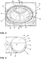
- the deflector 38 is illustrated extending approximately 180° around the bottom portion 46 of the aperture 18. Side portions 82, 86 of the deflector 38 extend proximate an upper portion 68 of the aperture 18. According to various aspects, the deflector 38 can extend approximately to a midpoint 70 on each of the left and right sides 74, 78 of the aperture 18, the midpoint 70 being approximately half the height h 1 of the aperture 18.
- the deflector 38 may extend to a point below the midpoint 70 and/or may extend to a point above the midpoint 70. It is contemplated that the side portions 82, 86 of the deflector 38 extends approximately a same height h 2 , such that the side portions 82, 86 are substantially mirror images of one another over a ⁇ -axis 90 of the aperture 18. It is also contemplated that the side portions 82, 86 of the deflector may not extend to a same height h 2 , such that the side portions 82, 86 may not be substantially mirror images of one another over the ⁇ -axis 90.
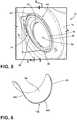
- the cabinet 14 includes a flange 94 around the aperture 18.
- the flange 94 can extend from the cabinet 14 towards a center portion 98 of the aperture 18.
- the deflector 38 is coupled to an inner surface 102 ( FIG. 17 ) of the flange 94. It is contemplated that the deflector 38 may be coupled to other portions of the cabinet 14 proximate the aperture 18.
- the deflector 38 includes the arcuate body 54 and a drip edge 106.
- the deflector 38 is configured as an obliquely-oriented cylindrical section and/or an angled chute.
- the drip edge 106 is a bottom interior edge 108 of the deflector 38 disposed within the interior 42 ( FIG. 1 ) of the drum 26.
- the deflector 38 can also include a rim 110 configured to correspond with the flange 94 ( FIG. 5 ) proximate the aperture 18 ( FIG. 1 ).
- a width w 1 of the deflector 38 corresponds with a width w 2 ( FIG. 4 ) of the aperture 18 ( FIG. 3 ).
- the width w 1 may be in a range of from approximately 350 mm to approximately 450 mm.
- the deflector 38 may also have the height h 2 in a range of from approximately 270 mm to approximately 380 mm. Additionally, the deflector 38 can have a bottom depth (e.g., a first depth) d 1 in a range of from approximately 50 mm to approximately 150 mm. It is contemplated that the width w 1 , the height h 2 , and/or the bottom depth d 1 can vary based on the type, model, and/or size of the washer 10 and/or laundry appliance in which the deflector 38 is coupled.
- the deflector 38 includes the side portions 82, 86 that extend a shorter distance toward the interior 42 ( FIG. 1 ) of the drum 26 ( FIG. 1 ) compared to a bottom 114 of the deflector 38.
- the bottom depth d 1 is typically greater compared to a side depth d 2 (e.g., a second depth).
- the bottom depth d 1 and the side depth d 2 may be substantially similar.
- the side depth d 2 may decrease and/or taper, such that the side depth d 2 decreases further from the bottom depth d 1 .
- the side depth d 2 can decrease in a linear manner, a parabolic manner, and/or any other practicable manner.
- the deflector 38 typically includes a lower extension 118 that defines the bottom 114 of the deflector 38.
- the lower extension 118 extends at an oblique-orientation toward a lower portion 58 of the drum 26. Stated differently, the lower extension 118 forms the angled surface 50 of the deflector 38.
- the lower extension 118 often includes the drip edge 106.
- the drip edge 106 extends downward from the lower extension 118 of the deflector 38 toward and/or into the drum 26. In various examples, the drip edge 106 has a thickness greater than the thickness of the arcuate body 54 of the deflector 38.
- the drip edge 106 allows water on the deflector 38 to drip from the deflector 38 into the lower portion 58 of the drum 26.
- the drip edge 106 may also operate to direct the laundry 66 ( FIG. 2 ) to stay within the interior 42 of the drum 26. Additionally, the drip edge 106 can be advantageous to control water flow within the drum 26 and/or to protect the bellows 34 (e.g., prevent the laundry 66 from coming into contact with the bellows 34).
- the deflector 38 is shown having a variety of shapes and configurations.
- the deflector 38 extends toward the interior 42 of the drum 26 at different angles based on the height h 2 of the deflector 38.
- the side interior edge 122 of the deflector 38 has different sloped configurations based on the shape and/or size of the deflector 38.
- the deflector 38 is coupled to less than 180° of the perimeter of the aperture 18 of the cabinet 14. In such examples, the deflector 38 may be coupled to approximately 90° of the perimeter of the aperture 18 along the bottom portion 46 of the aperture 18. In such examples, a side interior edge 122 of the deflector 38 arches downward to the bottom interior edge 108.
- the side interior edge 122 of the side portions 82, 86 include an inward extension 126 that extends inward towards the interior 42 of the drum 26.
- the side interior edge 122 additionally or alternatively, includes a sloped portion 130 that extends downward at a greater angle compared to the inward extension 126 until the side interior edge 122 meets the drip edge 106.
- each of the side portions 82, 86 ( FIG. 7 ) of the deflector 38 include the inward extension 126 and the sloped portion 130 that slopes at an oblique-orientation between the inward extension 126 and the lower extension 118.
- a bottom surface 134 of the deflector 38 typically slopes toward the drip edge 106 in a generally consistent uniform slope.
- the side interior edge 122 includes the sloped portion 130 that extends at a uniform slope towards the drip edge 106.
- the deflector 38 may not include the inward extension 126, or alternatively, may include a smaller inward extension 126 relative to the deflector 38 illustrated in FIG. 9 .
- the difference in shape of the deflector 38 based on the height h 2 of the deflector 38 typically allows the differently shaped deflectors 38 to similarly operate to provide the same benefits for a variety of appliance designs.
- the deflector 38 having the sloped and/or arched side interior edges 122 can operate to direct water and/or laundry 66 away from the aperture 18 toward the interior 42 of the drum 26.
- the shape of the deflector 38 can be informed by the geometry of the bellows 34.
- the deflector 38 may include a tab 138 that extends from a front edge 142 thereof.
- the tab 138 is configured to cooperate with the flange 94 and/or cabinet 14 of the washer 10 to hold the deflector 38 to the cabinet 14.
- the deflector 38 is configured as a cantilevered cylindrical extrusion that extends from the cabinet 14.
- the front edge 142 and the interior edge 108 can have a thickness greater than the thickness of the arcuate body 54 of the deflector 38.
- the side interior and front edges 122, 142 of the deflector 38 have a rolled shape, such that the side interior and front edges 122, 142 extend from the arcuate body 54 and roll back towards the arcuate body 54.
- the rolled shape can operate to direct laundry 66 toward the interior 42 of the drum 26.
- the deflector 38 may be configured to deform and/or bend toward the cabinet 14.
- a space is defined between the drip edge 106 and the cabinet 14 proximate where the bellows 34 couples to the cabinet 14.
- the drip edge 106 moves into the space, closer to where the bellows 34 couples to the cabinet 14.
- the deflector 38 can be configured as a living hinge.
- the deflector 38 could elastically deform.
- the deflector 38 can include a hinge assembly, such that at least a portion of the lower extension 118 can rotate about the hinge assembly toward the cabinet 14.
- the deflector 38 may extend the entire perimeter of the aperture 18 and be configured as a conical or cylindrical extrusion. Accordingly, the deflector 38 engages an entire perimeter of the bellows 34 and extends over the lower portion of the bellows 34.
- the deflector 38 includes side portions 82, 86 that extend between a top 162 and the bottom 114 of the deflector 38 and include the respective sloping side interior edges 122.
- the deflector 38 can include the tab 138 extending from the arcuate body 54. Additionally, the deflector 38 forms a circular and/or oblong shape to cooperatively mirror the shape of the aperture 18. In this way, the shape and/or size of the tab 138 is configured to correspond with the aperture 18.
- the bottom depth d 1 is typically greater than the side depth d 2 .
- a top depth d 3 (e.g., a third depth) is typically lesser than both the side depth d 2 and the bottom depth d 1 . Accordingly, the bottom 114 of the deflector 38 extends a greater distance towards the interior 42 of the drum 26 ( FIG. 1 ) compared to the top 162 of the deflector 38.
- the side depth d 2 decreases and/or tapers, such that the side depth d 2 decreases further from the bottom depth d 1 . Stated differently, the side portions 82, 86 have an increasing side depth d 2 from proximate the top 162 to proximate the bottom 114.
- the deflector 38 can have a height h 2 in a range of from approximately 450 mm to approximately 550 mm.
- the deflector 38 may also have a width w 1 in a range of from approximately 350 mm to approximately 450 mm.
- the bottom depth d 1 may be in a range of from approximately 50 mm to approximately 150 mm.
- the width w , height h 2 , and bottom depth d 1 may vary based on the type, model, and/or size of the washer 10 ( FIG. 1 ) and/or laundry appliance for which the deflector 38 is utilized.
- the side interior edge 122 of the deflector 38 typically slopes downward at a uniform angle to the drip edge 106.
- the bottom surface 134 extends at a uniform angle towards the drip edge 106, but may be a different angle compared to the side interior edge 122.
- the bottom surface 134 and the side interior edge 122 extend at different angles to form a funnel-shaped deflector 38, such that the deflector 38 substantially avoids contact with the bellows 34 when the washer 10 is in use.
- the flange 94 is positioned to at least partially overlap the aperture 18 and extends inward toward the bellows 34. This configuration prevents infiltration of fluid between the deflector 38 and the aperture 18.
- the rim 110 and/or the tab 138 ( FIG. 11 ) of the deflector 38 are configured to cooperate with the flange 94, such that the deflector 38 is positioned on an upward-facing surface 166, such as a ledge, of the flange 94.
- the flange 94 may also extend towards the center portion 98 of the aperture 18.
- the tab 138 ( FIG. 11 ) of the deflector 38 is configured to cooperate with the inner surface 102 of the flange 94.
- the tab 138 and/or the rim 110 of the deflector 38 may extend horizontally or vertically away from the arcuate body 54 of the deflector 38 based on the orientation of the flange 94.
- the deflector 38 can be included with the washer 10 to improve the aesthetics of the aperture 18 of the washer 10.
- the use of the deflector 38 is advantageous such that when consumers load and unload the laundry 66 ( FIG. 2 ) from within the washer 10, the consumer can avoid contact with the bellows 34.
- the deflector 38 can be configured as a bib and/or an angled chute to extend over the bellows 34 toward the interior 42 of the drum 26.
- a top surface 168 of the arcuate body 54 may also be decorated to improve the aesthetics of the washer 10 and/or the deflector 38.
- the decorations may include, for example, artwork, designs, instruction labels, and/or a combination thereof.
- the tapered shape at the deflector 38 also allows for a flow of fluid from near the bellows 34 into the tub 36.
- the aperture 18 is defined by the cabinet 14 along a first plane.
- the access opening 62 of the drum 26 is defined along a second plane.
- the interior edge 108 of the deflector 38 extends along a third plane.
- the first, second, and third planes are typically different from one another.
- the first plane may be substantially vertical and arranged parallel to the front surface 22 of the cabinet 14.
- the second plane is obliquely-oriented at a first angle relative to the first plane.
- the third plane is additionally obliquely-oriented at a second angle relative to the first plane and a different third angle relative to the second plane.
- the configuration of the obliquely-oriented second and third planes is advantageous for directing the laundry 66 and/or water into the interior 42 of the drum 26.
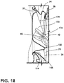
- the door 30 may be a swing door coupled to the cabinet 14 that includes a glass bowl panel 170.
- the glass bowl panel 170 extends toward the interior 42 of the drum 26 when the door 30 is in a closed position. In such examples, the glass bowl panel 170 curves and protrudes towards and/or into the drum 26.
- a central portion 174 and a bottom portion 180 of the glass bowl panel 170 typically extends a greater distance towards the drum 26 than a top portion 178.
- the central and bottom portions 174, 180 typically extend a same distance toward the interior 42 of the drum 26.
- the glass bowl panel 170 may operate in a similar manner as the deflector 38 by directing the laundry 66 away from the door 30 and into the interior 42 of the drum 26.
- the glass bowl panel 170 can be used in combination with the deflector 38.
- the bottom 114 of the deflector 38 extends a greater distance into the interior 42 of the drum 26 than the glass bowl panel 170.
- the glass bowl panel 170 is shaped to avoid contact with the deflector 38 when the door 30 is in the closed position.
- the deflector 38 extends around the glass bowl panel 170 when the door 30 is in the closed position. This configuration is advantageous for preventing contact and/or interference between the glass bowl panel 170 and the deflector 38. This configuration is also advantageous for preventing the laundry 66 from getting caught between the deflector 38 and the glass bowl panel 170.
- the door 30 may be a substantially planar panel swing door.
- an exterior surface 182 and an interior surface 186 of the door 30 are substantially flat.
- Having a flat panel door 30 is advantageous to improve the aesthetics of the washer 10 while using the deflector 38 to deflect laundry 66 ( FIG. 2 ) rather than the glass bowl panel 170 ( FIG. 18 ).
- the deflector 38 and the flat panel door 30 may also improve user access to the drum 26 and usability of the washer 10.
- use of the deflector 38 is advantageous to allow use of the flat panel door 30 on washers 10 that have dimension constraints, which can prevent or hinder the use of the glass bowl panel 170 ( FIG. 18 ).
- the door 30 may be a sliding glass panel 190 configured to slide from a position covering the aperture 18 to a downward location within the cabinet 14 of the washer 10 to allow access to the drum 26.
- the cabinet 14 of the washer 10 defines a slot 194 for accessing a chamber 198 proximate the front surface 22 of the cabinet 14.
- the cabinet 14 defines the chamber 198 for receiving and housing the sliding glass panel 190 in the opened position.
- the sliding glass panel 190 slidably engages the chamber 198.
- the sliding glass panel 190 typically includes a handle 202 to allow the consumer to move the sliding glass panel 190 over the aperture 18 and/or into the chamber 198.
- the sliding glass panel 190 is illustrated in the chamber 198 positioned below the aperture 18, such that a consumer can pull the sliding glass panel 190 upwards to position the sliding glass panel 190 over the aperture 18.
- the chamber 198 can be positioned in another location proximate the aperture 18 and, accordingly, the sliding glass panel 190 can be configured to move sideways and/or downwards to be positioned over the aperture 18.
- the sliding glass panel 190 may be a single pane glass panel.
- the sliding glass panel 190 may be a double pane glass panel, which may be advantageous for high heat laundry applications.
- the sliding glass panel 190 may also be motorized.
- a user can activate a motor to operate the sliding glass panel 190.
- a control for the motor and/or motorized sliding glass door 190 may be incorporated into a user-interface of the washer 10 or may be a separate controller. Additionally, use of the deflector 38 in the washer 10 allows for the use of the sliding glass panel 190 as the door 30.
- the cabinet 14 of the washer 10 may have a width w 3 in a range of from approximately 40 cm to approximately 100 cm.
- the cabinet 14 can also have a height h 3 in a range of from approximately 60 cm to approximately 130 cm.
- the aperture 18 may have a width w 2 in a range of from approximately 20 cm to approximately 60 cm.
- the cabinet 14 may have dimensions including the width w 3 of approximately 68 cm and the height h 3 of approximately 96 cm, with the aperture 18 having the width or diameter w 2 of approximately 40 cm.
- the slot 194 that provides the access point for the chamber 198 can be positioned in a range of from approximately 20 cm to approximately 60 cm above a bottom surface 206 of the washer 10 (i.e., spaced away from a floor).
- the sliding glass panel 190 is typically positioned directly below the aperture 18 in the cabinet 14 and is movable into and out of the chamber 198.
- the cabinet 14 of the washer 10 can have a width w 3 in a range of from approximately 30 cm to approximately 90 cm.
- the cabinet 14 may also have a height h 3 in a range of from approximately 50 cm to approximately 110 cm.
- the cabinet 14 may have dimensions including the width w 3 of approximately 60 cm and the height h 3 of approximately 86 cm.
- the slot 194 that provides the access point for the chamber 198 can be positioned in a range of from approximately 15 cm to approximately 50 cm above the bottom surface 206 of the washer 10 (i.e., spaced away from a floor).
- the sliding glass panel 190 is typically positioned directly below the aperture 18 in the cabinet 14 and is movable into and out of the chamber 198.
- the deflector 38 can be associated with at least one of a fluid delivery system and/or a heat system of the laundry appliance 10.
- piping 210 extends from the fluid delivery system to the deflector 38.
- the piping 210 typically extends at least partially along an outer surface 214 of the deflector 38.
- the piping 210 may be integrally formed with the deflector 38, or alternatively, may be coupled to the deflector 38 by coupling members, such as clips, snap features, or other fasteners.
- the piping 210 extends partially, or entirely, around a perimeter of the deflector 38.
- the piping 210 is coupled to one or more spray nozzles 218 coupled to the deflector 38. As illustrated in FIG. 21 , four spray nozzles 218 are coupled to the deflector 38. One deflector 38 is in fluid communication with the top 162, one spray nozzle 218 is coupled to each of the side portions 82, 86, and one spray nozzle 218 is coupled to the bottom 114 of the deflector 38. However, it is contemplated that the deflector 38 may couple with any practicable number of spray nozzles 218 in any practicable location and/or arrangement on the deflector 38. According to various aspects, fluid travels from the fluid system, through the piping 210, and through the spray nozzles 218 toward the drum 26 and/or along the deflector 38. The fluid can be supplied to the drum 26 and/or be used to clean the deflector 38.
- the spray nozzles 218 may be used in addition to or as an alternative for spray nozzles 218 associated with the bellows 34 or other features of the laundry appliance 10.
- the deflector 38 may additionally or alternatively be associated with the heating system of the laundry appliance 10.
- ductwork 222 extends from the heat system to the deflector 38.
- the ductwork 222 typically extends at least partially along the outer surface 214 of the deflector 38.
- the ductwork 222 may be integrally formed with the deflector 38, or alternatively, may be coupled to the deflector 38 by coupling members, such as clips, snap features, or other fasteners.
- the ductwork 222 extends partially, or entirely, around the perimeter of the deflector 38.
- the ductwork 222 is in fluid communication with one or more inlets 226. As illustrated in FIG. 21 , the deflector defines three inlets 226.
- One inlet 226 is defined in the top 162 of the deflector 38 and one inlet 226 is defined in each of the side portions 82, 86.
- the deflector 38 may include any practicable number of inlets 226 in any practicable location and/or arrangement on the deflector 38. Air flows from the heat system, through the ductwork 222, and through the inlets 226 toward the drum 26. The airflow from proximate the deflector 38 is advantageous in combined washer/dryer configurations to provide additional access points for the air into the drum 26, which can increase the efficiency of the drying process.
- the ductwork 222 and inlets 226 can be used in addition to, or as an alternative to, any heating elements associated with the bellows 34 or other features of the laundry appliance 10.
- the deflector 38 is a substantially stationary feature of the laundry appliance 10, and coupling the piping 210 and/or ductwork 222 to the stationary deflector 38 is advantageous for decreasing vibrations of the various components. It is contemplated that the laundry appliance 10 can include the deflector 38 associated with one or both of the water system and the heat system.
- the washer 10 can limit the use of the fishbowl-style door by including the deflector 38.
- the washer 10 of the present disclosure can provide for the horizontal-axis washer 10 with the deflector 38 to direct laundry 66 into the drum 26 and/or away from the bellows 34.
- use of the deflector 38 can also allow use of the flat panel swing door 30.
- use of the deflector 38 can allow for the washer 10 to include the sliding glass panel 190 as the door 30. Additional benefits of using this device may be realized and/or achieved.
- a laundry appliance includes a cabinet defining an aperture in a front surface thereof.
- a drum is disposed within the cabinet.
- the drum defines an access opening that aligns with the aperture.
- a door is coupled to the cabinet and is operable between closed and opened positions relative to the aperture.
- a bellows extends along a perimeter of the aperture and proximate the access opening.
- a deflector extends along at least a portion of the perimeter of the aperture. The deflector extends into an interior of the drum over the bellows.
- a deflector extends along an entire perimeter of an aperture.
- a top of the deflector extends a top depth toward an interior of a drum and a bottom extends a bottom depth.
- the bottom depth is greater than the top depth.
- side portions of the deflector extend a side depth toward an interior of the drum.
- the side depth is greater than a top depth and less than a bottom depth.
- exterior and interior surfaces of a door are substantially planar.
- an aperture is defined on a first plane
- an access opening is defined on a second plane
- an interior edge of a deflector extends along a third plane.
- Each of the first, second, and third planes are different.
- a spray nozzle is coupled to a deflector for providing fluid to a drum.
- a laundry appliance includes a cabinet that defines an aperture.
- a drum is disposed within the cabinet.
- the drum defines an access opening that aligns with the aperture.
- a bellows is coupled to the cabinet proximate the aperture.
- a deflector is coupled to the cabinet proximate the aperture and extends toward the drum over the bellows.
- the deflector includes a top coupled proximate an upper portion of the aperture and a bottom coupled to a bottom portion of the aperture. The bottom has a greater depth than the top.
- a deflector includes side portions that extend between a top and a bottom.
- the side portions include respective sloping side edges.
- side portions have an increasing depth from proximate a top of a deflector to proximate a bottom defined by sloping side edges.
- an aperture defines a perimeter.
- a deflector extends along the entire perimeter of the aperture.
- a door is coupled to a cabinet. Exterior and interior surfaces of the door are substantially planar.
- a cabinet defines a chamber proximate an aperture.
- a door is slidably engaged with a cabinet and configured to slide into a chamber in an opened position and over an aperture in a closed position.
- a lower extension of a deflector extends at an oblique-orientation toward a lower portion of the drum.
- a laundry appliance includes a cabinet that defines an aperture.
- a tub is positioned within the cabinet.
- a drum is positioned within the tub.
- the tub defines an interior.
- a bellows is coupled to the cabinet and extends between the cabinet and the tub.
- a deflector is coupled to the cabinet proximate the aperture.
- the deflector includes a bottom and side portions extending therefrom. The bottom is coupled to the cabinet proximate a lower portion of the aperture and the side portions are coupled to the cabinet proximate respective sides of the aperture.
- each side portion includes an inward extension that extends towards an interior of a drum and a sloped portion that slopes at an oblique-orientation between the inward extension and a lower extension.
- a door is coupled to the cabinet.
- the door is a sliding glass panel.
- a cabinet defines a chamber for receiving a door when in an opened position.
- a deflector extends less than 180° around a perimeter of an aperture.
Landscapes
- Engineering & Computer Science (AREA)
- Textile Engineering (AREA)
- Main Body Construction Of Washing Machines And Laundry Dryers (AREA)
Applications Claiming Priority (2)
| Application Number | Priority Date | Filing Date | Title |
|---|---|---|---|
| US201862786366P | 2018-12-29 | 2018-12-29 | |
| US16/668,579 US11208750B2 (en) | 2018-12-29 | 2019-10-30 | Laundry appliance with a deflector |
Publications (2)
| Publication Number | Publication Date |
|---|---|
| EP3674468A1 true EP3674468A1 (de) | 2020-07-01 |
| EP3674468B1 EP3674468B1 (de) | 2021-05-19 |
Family
ID=68841020
Family Applications (1)
| Application Number | Title | Priority Date | Filing Date |
|---|---|---|---|
| EP19214627.2A Active EP3674468B1 (de) | 2018-12-29 | 2019-12-09 | Waschgerät mit einem deflektor |
Country Status (2)
| Country | Link |
|---|---|
| US (4) | US11208750B2 (de) |
| EP (1) | EP3674468B1 (de) |
Families Citing this family (3)
| Publication number | Priority date | Publication date | Assignee | Title |
|---|---|---|---|---|
| US10132021B2 (en) * | 2016-09-02 | 2018-11-20 | Whirlpool Corporation | Laundry treating appliance door assembly comprising a plastic fishbowl |
| US12084803B2 (en) | 2021-06-15 | 2024-09-10 | Whirlpool Corporation | Laundry appliance with sliding door system |
| US12522967B2 (en) | 2022-05-27 | 2026-01-13 | Whirlpool Corporation | Deflector assembly for laundry appliance |
Citations (5)
| Publication number | Priority date | Publication date | Assignee | Title |
|---|---|---|---|---|
| DE19706283A1 (de) * | 1997-02-18 | 1998-08-20 | Bosch Siemens Hausgeraete | Mantelseitig beschickbare Trommelwaschmaschine |
| EP1522623A1 (de) * | 2003-10-08 | 2005-04-13 | CANDY S.p.A. | Frontbeschickbare Waschmaschine |
| JP2007202741A (ja) * | 2006-02-01 | 2007-08-16 | Mitsubishi Electric Corp | 洗濯機 |
| US20130276322A1 (en) * | 2012-04-24 | 2013-10-24 | Whirlpool Corporation | Laundry treating appliance door with planar window element and projection |
| US20160145790A1 (en) * | 2014-11-20 | 2016-05-26 | Whirlpool Corporation | Laundry treating appliance with laundry deflector |
Family Cites Families (53)
| Publication number | Priority date | Publication date | Assignee | Title |
|---|---|---|---|---|
| US2941390A (en) | 1957-03-26 | 1960-06-21 | Gen Motors Corp | Vibration responsive mechanism for a domestic appliance |
| US3498089A (en) | 1968-06-28 | 1970-03-03 | Mc Graw Edison Co | Laundry machine |
| US4510776A (en) * | 1983-12-27 | 1985-04-16 | The Maytag Company | Sliding access door for washing machine |
| US6256823B1 (en) | 1999-06-29 | 2001-07-10 | The Chardon Rubber Company | Bellows for front loading washing machines |
| EP1285986B1 (de) | 2001-08-14 | 2004-07-28 | CANDY S.p.A. | Verbesserte Waschmaschine |
| EP1321558A1 (de) | 2001-12-20 | 2003-06-25 | CANDY S.p.A. | Faltenbalg für eine frontbeschickbare Waschmaschine |
| KR100465691B1 (ko) | 2002-01-17 | 2005-01-13 | 엘지전자 주식회사 | 드럼 세탁기의 도어 장착구조 |
| DE60235449D1 (de) | 2002-05-29 | 2010-04-08 | Candy Spa | Tür für Waschmaschinen oder Wäschetrockner |
| EP1408150B1 (de) | 2002-10-07 | 2008-09-03 | CANDY S.p.A. | System zum Öffnen und Schliessen für Waschmaschinen und/oder Trockner |
| KR100484838B1 (ko) | 2002-11-29 | 2005-04-22 | 엘지전자 주식회사 | 드럼세탁기의 개스킷 |
| DE10323494A1 (de) | 2003-05-23 | 2004-12-30 | BSH Bosch und Siemens Hausgeräte GmbH | Wäschetrockner |
| KR100716255B1 (ko) | 2003-07-23 | 2007-05-08 | 삼성전자주식회사 | 드럼세탁기 |
| KR100608259B1 (ko) | 2004-08-27 | 2006-08-09 | 삼성전자주식회사 | 드럼세탁기 |
| DE102004043671B4 (de) | 2004-09-07 | 2008-04-10 | Miele & Cie. Kg | Frontbeschickbare Trommelwaschmaschine mit Wäscheabweiser an der Faltenbalgdichtung |
| KR100600762B1 (ko) | 2004-10-22 | 2006-07-18 | 엘지전자 주식회사 | 상하 자동 개폐식 도어를 갖는 드럼 세탁기 |
| JP3862721B2 (ja) * | 2004-11-18 | 2006-12-27 | シャープ株式会社 | 乾燥機 |
| JP2006204576A (ja) | 2005-01-28 | 2006-08-10 | Sharp Corp | 洗濯機 |
| EP1690969A1 (de) | 2005-02-10 | 2006-08-16 | Electrolux Home Products Corporation N.V. | Verbesserung des vorderen Randes einer Haushaltswaschmaschine |
| DE102005015551B4 (de) | 2005-04-04 | 2008-08-07 | Miele & Cie. Kg | Frontbeschickbare Wäschebehandlungsmaschine wie Waschmaschine, Wäschetrockner oder Waschtrockner |
| JP3949145B2 (ja) | 2005-05-13 | 2007-07-25 | シャープ株式会社 | ドラム式洗濯機 |
| US8016444B2 (en) | 2005-08-18 | 2011-09-13 | Lg Electronics Inc. | Washing machine having lamp device and control method of the same |
| ES2276625B1 (es) | 2005-12-02 | 2008-04-16 | Bsh Electrodomesticos España, S.A. | Junta para lavadora y lavadora con dicha junta. |
| JP4781287B2 (ja) | 2007-01-25 | 2011-09-28 | 三洋電機株式会社 | 電気洗濯機 |
| DE102007009509B4 (de) | 2007-02-27 | 2016-06-02 | BSH Hausgeräte GmbH | Wäscheabweiservorrichtung für ein Hausgerät zur Pflege von Wäschestücken sowie ein derartiges Hausgerät |
| JP2009118948A (ja) | 2007-11-13 | 2009-06-04 | Sharp Corp | ドラム式洗濯機 |
| EP2078777B1 (de) | 2008-01-14 | 2016-04-13 | Electrolux Home Products Corporation N.V. | Waschmaschine mit verbesserten Dichtungsbälgen |
| DE102008004524B3 (de) | 2008-01-15 | 2009-01-29 | Miele & Cie. Kg | Frontbeschickbare Trommelwaschmaschine mit Wäscheabweiser |
| KR101590371B1 (ko) | 2009-02-16 | 2016-02-02 | 엘지전자 주식회사 | 세탁물 처리기기 및 세탁방법 |
| KR101604688B1 (ko) | 2009-05-04 | 2016-03-18 | 엘지전자 주식회사 | 세탁장치 |
| KR101692726B1 (ko) | 2009-05-28 | 2017-01-04 | 엘지전자 주식회사 | 세탁장치 |
| CN104313835B (zh) | 2009-08-27 | 2017-04-05 | 松下电器产业株式会社 | 滚筒式洗衣机 |
| US9045853B2 (en) | 2009-10-13 | 2015-06-02 | Lg Electronics Inc. | Laundry treating apparatus |
| KR101702972B1 (ko) | 2010-02-26 | 2017-02-06 | 엘지전자 주식회사 | 건조기 |
| PL2453053T3 (pl) | 2010-11-15 | 2019-09-30 | Electrolux Home Products Corporation N.V. | Maszyna do materiałów pranych |
| US9822475B2 (en) | 2011-10-14 | 2017-11-21 | Jensen Usa Inc. | Loading device for a laundry machine |
| US9469931B2 (en) | 2011-12-21 | 2016-10-18 | Whirlpool Corporation | Laundry treating appliance door with planar window element and baffle for controlling laundry movement |
| ES2446115B1 (es) | 2012-09-06 | 2015-03-06 | Bsh Electrodomesticos Espana | Junta anular de embocadura para una máquina lavadora de carga frontal con sistema de remojado de colada y máquina lavadora de carga frontal que comprende la junta |
| US9466439B2 (en) | 2013-06-26 | 2016-10-11 | Whirlpool Corporation | Laundry treating appliance and method of operation for a laundry treating appliance |
| US20150019017A1 (en) | 2013-07-12 | 2015-01-15 | Whirlpool Corporation | Home appliance and method of operating a home appliance |
| BR112016020398B1 (pt) | 2014-03-04 | 2022-07-05 | Lg Electronics Inc | Máquina de lavagem |
| CN103911812B (zh) | 2014-03-04 | 2016-02-03 | 江苏神农灭菌设备股份有限公司 | 灭菌洗衣机的灭菌及平移门的连接结构 |
| DE102015216363A1 (de) * | 2015-08-27 | 2017-03-02 | BSH Hausgeräte GmbH | Waschmaschine mit Türbereich zur Vermeidung von Wäscheschäden |
| JP6543805B2 (ja) | 2015-09-07 | 2019-07-17 | パナソニックIpマネジメント株式会社 | ドラム式洗濯機 |
| KR102459165B1 (ko) | 2015-11-18 | 2022-10-27 | 삼성전자주식회사 | 세탁기 |
| KR102471461B1 (ko) | 2015-12-09 | 2022-11-28 | 삼성전자주식회사 | 세탁기 |
| KR102512212B1 (ko) | 2016-02-23 | 2023-03-22 | 삼성전자주식회사 | 세탁기 및 그 제어방법 |
| US10132021B2 (en) | 2016-09-02 | 2018-11-20 | Whirlpool Corporation | Laundry treating appliance door assembly comprising a plastic fishbowl |
| CN207193607U (zh) | 2017-09-25 | 2018-04-06 | 山东大成洗涤机械有限公司 | 一种自动升降门 |
| CN107401030A (zh) | 2017-09-25 | 2017-11-28 | 山东大成洗涤机械有限公司 | 一种自动升降门 |
| USD856615S1 (en) | 2017-10-19 | 2019-08-13 | Whirlpool Corporation | Door bowl for a laundry treating appliance door |
| DE102018101299A1 (de) | 2018-01-22 | 2019-07-25 | Miele & Cie. Kg | Trommelwaschmaschine |
| CN208266517U (zh) | 2018-05-25 | 2018-12-21 | 山东大成洗涤机械有限公司 | 一种自动升降门 |
| US11242645B2 (en) | 2018-11-16 | 2022-02-08 | Whirlpool Corporation | Laundry treating appliance having a door assembly |
-
2019
- 2019-10-30 US US16/668,579 patent/US11208750B2/en active Active
- 2019-12-09 EP EP19214627.2A patent/EP3674468B1/de active Active
-
2021
- 2021-11-15 US US17/526,148 patent/US11946186B2/en active Active
-
2024
- 2024-03-18 US US18/608,152 patent/US12448717B2/en active Active
-
2025
- 2025-09-29 US US19/342,960 patent/US20260092408A1/en active Pending
Patent Citations (5)
| Publication number | Priority date | Publication date | Assignee | Title |
|---|---|---|---|---|
| DE19706283A1 (de) * | 1997-02-18 | 1998-08-20 | Bosch Siemens Hausgeraete | Mantelseitig beschickbare Trommelwaschmaschine |
| EP1522623A1 (de) * | 2003-10-08 | 2005-04-13 | CANDY S.p.A. | Frontbeschickbare Waschmaschine |
| JP2007202741A (ja) * | 2006-02-01 | 2007-08-16 | Mitsubishi Electric Corp | 洗濯機 |
| US20130276322A1 (en) * | 2012-04-24 | 2013-10-24 | Whirlpool Corporation | Laundry treating appliance door with planar window element and projection |
| US20160145790A1 (en) * | 2014-11-20 | 2016-05-26 | Whirlpool Corporation | Laundry treating appliance with laundry deflector |
Also Published As
| Publication number | Publication date |
|---|---|
| US20240218583A1 (en) | 2024-07-04 |
| US12448717B2 (en) | 2025-10-21 |
| US20200208324A1 (en) | 2020-07-02 |
| EP3674468B1 (de) | 2021-05-19 |
| US11946186B2 (en) | 2024-04-02 |
| US11208750B2 (en) | 2021-12-28 |
| US20260092408A1 (en) | 2026-04-02 |
| US20220074101A1 (en) | 2022-03-10 |
Similar Documents
| Publication | Publication Date | Title |
|---|---|---|
| US12448717B2 (en) | Laundry appliance with a deflector | |
| EP3118366A1 (de) | Wäschetrockner | |
| US7552545B2 (en) | Ducted drying rack for clothes dryer | |
| EP3351677B1 (de) | Wäschebehandlungsvorrichtung | |
| NZ543483A (en) | Clothes dryer drive and blower system | |
| EP3653779B1 (de) | Wäschebehandlungsgerät mit einer türanordnung | |
| EP1752713B1 (de) | Innenraumeinheit für klimaanlage | |
| US8857034B2 (en) | Method for manufacturing a dishwasher appliance | |
| CN112301622B (zh) | 衣物处理设备 | |
| KR102561876B1 (ko) | 의류처리장치 | |
| CN112376230B (zh) | 门组件及具有其的衣物处理设备 | |
| US11219310B2 (en) | Appliance pedestal system | |
| EP3124685A1 (de) | Wäschetrockner | |
| CN105755736B (zh) | 洗衣机 | |
| CN207515065U (zh) | 空调柜机 | |
| EP3040464B1 (de) | Waschmaschine | |
| EP1857585A1 (de) | Trockner | |
| CN112323415B (zh) | 面盖组件、工作台装置以及衣物处理设备 | |
| CN112301651B (zh) | 衣物处理设备及其工作台组件 | |
| US20240117990A1 (en) | Air conditioner | |
| CN215686968U (zh) | 烹饪器具 | |
| JP3515878B2 (ja) | 食器乾燥器 | |
| TR201908846A2 (tr) | Üst tablaya sahi̇p bi̇r ev ci̇hazi | |
| CN112301663A (zh) | 衣物处理设备及其工作台装置 | |
| JPH06300A (ja) | 衣類プレス機能付きアイロンユニット |
Legal Events
| Date | Code | Title | Description |
|---|---|---|---|
| PUAI | Public reference made under article 153(3) epc to a published international application that has entered the european phase |
Free format text: ORIGINAL CODE: 0009012 |
|
| STAA | Information on the status of an ep patent application or granted ep patent |
Free format text: STATUS: THE APPLICATION HAS BEEN PUBLISHED |
|
| AK | Designated contracting states |
Kind code of ref document: A1 Designated state(s): AL AT BE BG CH CY CZ DE DK EE ES FI FR GB GR HR HU IE IS IT LI LT LU LV MC MK MT NL NO PL PT RO RS SE SI SK SM TR |
|
| AX | Request for extension of the european patent |
Extension state: BA ME |
|
| STAA | Information on the status of an ep patent application or granted ep patent |
Free format text: STATUS: REQUEST FOR EXAMINATION WAS MADE |
|
| 17P | Request for examination filed |
Effective date: 20201208 |
|
| RBV | Designated contracting states (corrected) |
Designated state(s): AL AT BE BG CH CY CZ DE DK EE ES FI FR GB GR HR HU IE IS IT LI LT LU LV MC MK MT NL NO PL PT RO RS SE SI SK SM TR |
|
| GRAP | Despatch of communication of intention to grant a patent |
Free format text: ORIGINAL CODE: EPIDOSNIGR1 |
|
| STAA | Information on the status of an ep patent application or granted ep patent |
Free format text: STATUS: GRANT OF PATENT IS INTENDED |
|
| RIC1 | Information provided on ipc code assigned before grant |
Ipc: D06F 37/26 20060101AFI20210201BHEP Ipc: D06F 39/14 20060101ALN20210201BHEP |
|
| INTG | Intention to grant announced |
Effective date: 20210305 |
|
| GRAS | Grant fee paid |
Free format text: ORIGINAL CODE: EPIDOSNIGR3 |
|
| GRAA | (expected) grant |
Free format text: ORIGINAL CODE: 0009210 |
|
| STAA | Information on the status of an ep patent application or granted ep patent |
Free format text: STATUS: THE PATENT HAS BEEN GRANTED |
|
| AK | Designated contracting states |
Kind code of ref document: B1 Designated state(s): AL AT BE BG CH CY CZ DE DK EE ES FI FR GB GR HR HU IE IS IT LI LT LU LV MC MK MT NL NO PL PT RO RS SE SI SK SM TR |
|
| REG | Reference to a national code |
Ref country code: GB Ref legal event code: FG4D |
|
| REG | Reference to a national code |
Ref country code: CH Ref legal event code: EP |
|
| REG | Reference to a national code |
Ref country code: DE Ref legal event code: R096 Ref document number: 602019004743 Country of ref document: DE |
|
| REG | Reference to a national code |
Ref country code: AT Ref legal event code: REF Ref document number: 1394061 Country of ref document: AT Kind code of ref document: T Effective date: 20210615 |
|
| REG | Reference to a national code |
Ref country code: IE Ref legal event code: FG4D |
|
| REG | Reference to a national code |
Ref country code: LT Ref legal event code: MG9D |
|
| REG | Reference to a national code |
Ref country code: AT Ref legal event code: MK05 Ref document number: 1394061 Country of ref document: AT Kind code of ref document: T Effective date: 20210519 |
|
| REG | Reference to a national code |
Ref country code: NL Ref legal event code: MP Effective date: 20210519 |
|
| PG25 | Lapsed in a contracting state [announced via postgrant information from national office to epo] |
Ref country code: AT Free format text: LAPSE BECAUSE OF FAILURE TO SUBMIT A TRANSLATION OF THE DESCRIPTION OR TO PAY THE FEE WITHIN THE PRESCRIBED TIME-LIMIT Effective date: 20210519 Ref country code: BG Free format text: LAPSE BECAUSE OF FAILURE TO SUBMIT A TRANSLATION OF THE DESCRIPTION OR TO PAY THE FEE WITHIN THE PRESCRIBED TIME-LIMIT Effective date: 20210819 Ref country code: LT Free format text: LAPSE BECAUSE OF FAILURE TO SUBMIT A TRANSLATION OF THE DESCRIPTION OR TO PAY THE FEE WITHIN THE PRESCRIBED TIME-LIMIT Effective date: 20210519 Ref country code: HR Free format text: LAPSE BECAUSE OF FAILURE TO SUBMIT A TRANSLATION OF THE DESCRIPTION OR TO PAY THE FEE WITHIN THE PRESCRIBED TIME-LIMIT Effective date: 20210519 Ref country code: FI Free format text: LAPSE BECAUSE OF FAILURE TO SUBMIT A TRANSLATION OF THE DESCRIPTION OR TO PAY THE FEE WITHIN THE PRESCRIBED TIME-LIMIT Effective date: 20210519 |
|
| PG25 | Lapsed in a contracting state [announced via postgrant information from national office to epo] |
Ref country code: GR Free format text: LAPSE BECAUSE OF FAILURE TO SUBMIT A TRANSLATION OF THE DESCRIPTION OR TO PAY THE FEE WITHIN THE PRESCRIBED TIME-LIMIT Effective date: 20210820 Ref country code: IS Free format text: LAPSE BECAUSE OF FAILURE TO SUBMIT A TRANSLATION OF THE DESCRIPTION OR TO PAY THE FEE WITHIN THE PRESCRIBED TIME-LIMIT Effective date: 20210919 Ref country code: LV Free format text: LAPSE BECAUSE OF FAILURE TO SUBMIT A TRANSLATION OF THE DESCRIPTION OR TO PAY THE FEE WITHIN THE PRESCRIBED TIME-LIMIT Effective date: 20210519 Ref country code: NO Free format text: LAPSE BECAUSE OF FAILURE TO SUBMIT A TRANSLATION OF THE DESCRIPTION OR TO PAY THE FEE WITHIN THE PRESCRIBED TIME-LIMIT Effective date: 20210819 Ref country code: PL Free format text: LAPSE BECAUSE OF FAILURE TO SUBMIT A TRANSLATION OF THE DESCRIPTION OR TO PAY THE FEE WITHIN THE PRESCRIBED TIME-LIMIT Effective date: 20210519 Ref country code: PT Free format text: LAPSE BECAUSE OF FAILURE TO SUBMIT A TRANSLATION OF THE DESCRIPTION OR TO PAY THE FEE WITHIN THE PRESCRIBED TIME-LIMIT Effective date: 20210920 Ref country code: RS Free format text: LAPSE BECAUSE OF FAILURE TO SUBMIT A TRANSLATION OF THE DESCRIPTION OR TO PAY THE FEE WITHIN THE PRESCRIBED TIME-LIMIT Effective date: 20210519 Ref country code: SE Free format text: LAPSE BECAUSE OF FAILURE TO SUBMIT A TRANSLATION OF THE DESCRIPTION OR TO PAY THE FEE WITHIN THE PRESCRIBED TIME-LIMIT Effective date: 20210519 |
|
| PG25 | Lapsed in a contracting state [announced via postgrant information from national office to epo] |
Ref country code: NL Free format text: LAPSE BECAUSE OF FAILURE TO SUBMIT A TRANSLATION OF THE DESCRIPTION OR TO PAY THE FEE WITHIN THE PRESCRIBED TIME-LIMIT Effective date: 20210519 |
|
| PG25 | Lapsed in a contracting state [announced via postgrant information from national office to epo] |
Ref country code: SK Free format text: LAPSE BECAUSE OF FAILURE TO SUBMIT A TRANSLATION OF THE DESCRIPTION OR TO PAY THE FEE WITHIN THE PRESCRIBED TIME-LIMIT Effective date: 20210519 Ref country code: ES Free format text: LAPSE BECAUSE OF FAILURE TO SUBMIT A TRANSLATION OF THE DESCRIPTION OR TO PAY THE FEE WITHIN THE PRESCRIBED TIME-LIMIT Effective date: 20210519 Ref country code: EE Free format text: LAPSE BECAUSE OF FAILURE TO SUBMIT A TRANSLATION OF THE DESCRIPTION OR TO PAY THE FEE WITHIN THE PRESCRIBED TIME-LIMIT Effective date: 20210519 Ref country code: DK Free format text: LAPSE BECAUSE OF FAILURE TO SUBMIT A TRANSLATION OF THE DESCRIPTION OR TO PAY THE FEE WITHIN THE PRESCRIBED TIME-LIMIT Effective date: 20210519 Ref country code: CZ Free format text: LAPSE BECAUSE OF FAILURE TO SUBMIT A TRANSLATION OF THE DESCRIPTION OR TO PAY THE FEE WITHIN THE PRESCRIBED TIME-LIMIT Effective date: 20210519 Ref country code: RO Free format text: LAPSE BECAUSE OF FAILURE TO SUBMIT A TRANSLATION OF THE DESCRIPTION OR TO PAY THE FEE WITHIN THE PRESCRIBED TIME-LIMIT Effective date: 20210519 Ref country code: SM Free format text: LAPSE BECAUSE OF FAILURE TO SUBMIT A TRANSLATION OF THE DESCRIPTION OR TO PAY THE FEE WITHIN THE PRESCRIBED TIME-LIMIT Effective date: 20210519 |
|
| REG | Reference to a national code |
Ref country code: DE Ref legal event code: R097 Ref document number: 602019004743 Country of ref document: DE |
|
| PLBE | No opposition filed within time limit |
Free format text: ORIGINAL CODE: 0009261 |
|
| STAA | Information on the status of an ep patent application or granted ep patent |
Free format text: STATUS: NO OPPOSITION FILED WITHIN TIME LIMIT |
|
| 26N | No opposition filed |
Effective date: 20220222 |
|
| PG25 | Lapsed in a contracting state [announced via postgrant information from national office to epo] |
Ref country code: IS Free format text: LAPSE BECAUSE OF FAILURE TO SUBMIT A TRANSLATION OF THE DESCRIPTION OR TO PAY THE FEE WITHIN THE PRESCRIBED TIME-LIMIT Effective date: 20210919 Ref country code: AL Free format text: LAPSE BECAUSE OF FAILURE TO SUBMIT A TRANSLATION OF THE DESCRIPTION OR TO PAY THE FEE WITHIN THE PRESCRIBED TIME-LIMIT Effective date: 20210519 |
|
| PG25 | Lapsed in a contracting state [announced via postgrant information from national office to epo] |
Ref country code: MC Free format text: LAPSE BECAUSE OF FAILURE TO SUBMIT A TRANSLATION OF THE DESCRIPTION OR TO PAY THE FEE WITHIN THE PRESCRIBED TIME-LIMIT Effective date: 20210519 |
|
| REG | Reference to a national code |
Ref country code: BE Ref legal event code: MM Effective date: 20211231 |
|
| PG25 | Lapsed in a contracting state [announced via postgrant information from national office to epo] |
Ref country code: LU Free format text: LAPSE BECAUSE OF NON-PAYMENT OF DUE FEES Effective date: 20211209 Ref country code: IE Free format text: LAPSE BECAUSE OF NON-PAYMENT OF DUE FEES Effective date: 20211209 |
|
| PG25 | Lapsed in a contracting state [announced via postgrant information from national office to epo] |
Ref country code: BE Free format text: LAPSE BECAUSE OF NON-PAYMENT OF DUE FEES Effective date: 20211231 |
|
| P01 | Opt-out of the competence of the unified patent court (upc) registered |
Effective date: 20230522 |
|
| PG25 | Lapsed in a contracting state [announced via postgrant information from national office to epo] |
Ref country code: CY Free format text: LAPSE BECAUSE OF FAILURE TO SUBMIT A TRANSLATION OF THE DESCRIPTION OR TO PAY THE FEE WITHIN THE PRESCRIBED TIME-LIMIT Effective date: 20210519 |
|
| PG25 | Lapsed in a contracting state [announced via postgrant information from national office to epo] |
Ref country code: HU Free format text: LAPSE BECAUSE OF FAILURE TO SUBMIT A TRANSLATION OF THE DESCRIPTION OR TO PAY THE FEE WITHIN THE PRESCRIBED TIME-LIMIT; INVALID AB INITIO Effective date: 20191209 |
|
| REG | Reference to a national code |
Ref country code: CH Ref legal event code: PL |
|
| PG25 | Lapsed in a contracting state [announced via postgrant information from national office to epo] |
Ref country code: LI Free format text: LAPSE BECAUSE OF NON-PAYMENT OF DUE FEES Effective date: 20221231 Ref country code: CH Free format text: LAPSE BECAUSE OF NON-PAYMENT OF DUE FEES Effective date: 20221231 |
|
| PGFP | Annual fee paid to national office [announced via postgrant information from national office to epo] |
Ref country code: GB Payment date: 20231219 Year of fee payment: 5 |
|
| PGFP | Annual fee paid to national office [announced via postgrant information from national office to epo] |
Ref country code: IT Payment date: 20231221 Year of fee payment: 5 Ref country code: FR Payment date: 20231226 Year of fee payment: 5 |
|
| PG25 | Lapsed in a contracting state [announced via postgrant information from national office to epo] |
Ref country code: MK Free format text: LAPSE BECAUSE OF FAILURE TO SUBMIT A TRANSLATION OF THE DESCRIPTION OR TO PAY THE FEE WITHIN THE PRESCRIBED TIME-LIMIT Effective date: 20210519 |
|
| PGFP | Annual fee paid to national office [announced via postgrant information from national office to epo] |
Ref country code: DE Payment date: 20231227 Year of fee payment: 5 |
|
| PG25 | Lapsed in a contracting state [announced via postgrant information from national office to epo] |
Ref country code: TR Free format text: LAPSE BECAUSE OF FAILURE TO SUBMIT A TRANSLATION OF THE DESCRIPTION OR TO PAY THE FEE WITHIN THE PRESCRIBED TIME-LIMIT Effective date: 20210519 |
|
| PG25 | Lapsed in a contracting state [announced via postgrant information from national office to epo] |
Ref country code: MT Free format text: LAPSE BECAUSE OF FAILURE TO SUBMIT A TRANSLATION OF THE DESCRIPTION OR TO PAY THE FEE WITHIN THE PRESCRIBED TIME-LIMIT Effective date: 20210519 |
|
| REG | Reference to a national code |
Ref country code: DE Ref legal event code: R119 Ref document number: 602019004743 Country of ref document: DE |
|
| GBPC | Gb: european patent ceased through non-payment of renewal fee |
Effective date: 20241209 |
|
| PG25 | Lapsed in a contracting state [announced via postgrant information from national office to epo] |
Ref country code: DE Free format text: LAPSE BECAUSE OF NON-PAYMENT OF DUE FEES Effective date: 20250701 |
|
| PG25 | Lapsed in a contracting state [announced via postgrant information from national office to epo] |
Ref country code: IT Free format text: LAPSE BECAUSE OF NON-PAYMENT OF DUE FEES Effective date: 20241209 |
|
| PG25 | Lapsed in a contracting state [announced via postgrant information from national office to epo] |
Ref country code: GB Free format text: LAPSE BECAUSE OF NON-PAYMENT OF DUE FEES Effective date: 20241209 |
|
| PG25 | Lapsed in a contracting state [announced via postgrant information from national office to epo] |
Ref country code: FR Free format text: LAPSE BECAUSE OF NON-PAYMENT OF DUE FEES Effective date: 20241231 |