EP3674213B1 - Unbemanntes luftfahrzeug zum transport einer nutzlast - Google Patents
Unbemanntes luftfahrzeug zum transport einer nutzlast Download PDFInfo
- Publication number
- EP3674213B1 EP3674213B1 EP19219659.0A EP19219659A EP3674213B1 EP 3674213 B1 EP3674213 B1 EP 3674213B1 EP 19219659 A EP19219659 A EP 19219659A EP 3674213 B1 EP3674213 B1 EP 3674213B1
- Authority
- EP
- European Patent Office
- Prior art keywords
- wire
- hook
- cargo
- threshold value
- spool
- Prior art date
- Legal status (The legal status is an assumption and is not a legal conclusion. Google has not performed a legal analysis and makes no representation as to the accuracy of the status listed.)
- Active
Links
Images


Classifications
-
- B—PERFORMING OPERATIONS; TRANSPORTING
- B64—AIRCRAFT; AVIATION; COSMONAUTICS
- B64D—EQUIPMENT FOR FITTING IN OR TO AIRCRAFT; FLIGHT SUITS; PARACHUTES; ARRANGEMENT OR MOUNTING OF POWER PLANTS OR PROPULSION TRANSMISSIONS IN AIRCRAFT
- B64D1/00—Dropping, ejecting, releasing or receiving articles, liquids, or the like, in flight
-
- B—PERFORMING OPERATIONS; TRANSPORTING
- B64—AIRCRAFT; AVIATION; COSMONAUTICS
- B64D—EQUIPMENT FOR FITTING IN OR TO AIRCRAFT; FLIGHT SUITS; PARACHUTES; ARRANGEMENT OR MOUNTING OF POWER PLANTS OR PROPULSION TRANSMISSIONS IN AIRCRAFT
- B64D1/00—Dropping, ejecting, releasing or receiving articles, liquids, or the like, in flight
- B64D1/02—Dropping, ejecting, or releasing articles
- B64D1/08—Dropping, ejecting, or releasing articles the articles being load-carrying devices
- B64D1/12—Releasing
-
- B—PERFORMING OPERATIONS; TRANSPORTING
- B64—AIRCRAFT; AVIATION; COSMONAUTICS
- B64D—EQUIPMENT FOR FITTING IN OR TO AIRCRAFT; FLIGHT SUITS; PARACHUTES; ARRANGEMENT OR MOUNTING OF POWER PLANTS OR PROPULSION TRANSMISSIONS IN AIRCRAFT
- B64D1/00—Dropping, ejecting, releasing or receiving articles, liquids, or the like, in flight
- B64D1/22—Taking-up articles from earth's surface
-
- B—PERFORMING OPERATIONS; TRANSPORTING
- B64—AIRCRAFT; AVIATION; COSMONAUTICS
- B64D—EQUIPMENT FOR FITTING IN OR TO AIRCRAFT; FLIGHT SUITS; PARACHUTES; ARRANGEMENT OR MOUNTING OF POWER PLANTS OR PROPULSION TRANSMISSIONS IN AIRCRAFT
- B64D47/00—Equipment not otherwise provided for
- B64D47/02—Arrangements or adaptations of signal or lighting devices
-
- B—PERFORMING OPERATIONS; TRANSPORTING
- B66—HOISTING; LIFTING; HAULING
- B66D—CAPSTANS; WINCHES; TACKLES, e.g. PULLEY BLOCKS; HOISTS
- B66D1/00—Rope, cable, or chain winding mechanisms; Capstans
- B66D1/02—Driving gear
- B66D1/12—Driving gear incorporating electric motors
-
- B—PERFORMING OPERATIONS; TRANSPORTING
- B66—HOISTING; LIFTING; HAULING
- B66D—CAPSTANS; WINCHES; TACKLES, e.g. PULLEY BLOCKS; HOISTS
- B66D1/00—Rope, cable, or chain winding mechanisms; Capstans
- B66D1/28—Other constructional details
- B66D1/40—Control devices
- B66D1/48—Control devices automatic
- B66D1/485—Control devices automatic electrical
-
- B—PERFORMING OPERATIONS; TRANSPORTING
- B66—HOISTING; LIFTING; HAULING
- B66D—CAPSTANS; WINCHES; TACKLES, e.g. PULLEY BLOCKS; HOISTS
- B66D1/00—Rope, cable, or chain winding mechanisms; Capstans
- B66D1/54—Safety gear
-
- B—PERFORMING OPERATIONS; TRANSPORTING
- B64—AIRCRAFT; AVIATION; COSMONAUTICS
- B64D—EQUIPMENT FOR FITTING IN OR TO AIRCRAFT; FLIGHT SUITS; PARACHUTES; ARRANGEMENT OR MOUNTING OF POWER PLANTS OR PROPULSION TRANSMISSIONS IN AIRCRAFT
- B64D1/00—Dropping, ejecting, releasing or receiving articles, liquids, or the like, in flight
- B64D1/02—Dropping, ejecting, or releasing articles
-
- B—PERFORMING OPERATIONS; TRANSPORTING
- B64—AIRCRAFT; AVIATION; COSMONAUTICS
- B64U—UNMANNED AERIAL VEHICLES [UAV]; EQUIPMENT THEREFOR
- B64U10/00—Type of UAV
- B64U10/10—Rotorcrafts
- B64U10/13—Flying platforms
- B64U10/16—Flying platforms with five or more distinct rotor axes, e.g. octocopters
-
- B—PERFORMING OPERATIONS; TRANSPORTING
- B64—AIRCRAFT; AVIATION; COSMONAUTICS
- B64U—UNMANNED AERIAL VEHICLES [UAV]; EQUIPMENT THEREFOR
- B64U2101/00—UAVs specially adapted for particular uses or applications
- B64U2101/30—UAVs specially adapted for particular uses or applications for imaging, photography or videography
-
- B—PERFORMING OPERATIONS; TRANSPORTING
- B64—AIRCRAFT; AVIATION; COSMONAUTICS
- B64U—UNMANNED AERIAL VEHICLES [UAV]; EQUIPMENT THEREFOR
- B64U2101/00—UAVs specially adapted for particular uses or applications
- B64U2101/60—UAVs specially adapted for particular uses or applications for transporting passengers; for transporting goods other than weapons
- B64U2101/67—UAVs specially adapted for particular uses or applications for transporting passengers; for transporting goods other than weapons the UAVs comprising tethers for lowering the goods
-
- B—PERFORMING OPERATIONS; TRANSPORTING
- B64—AIRCRAFT; AVIATION; COSMONAUTICS
- B64U—UNMANNED AERIAL VEHICLES [UAV]; EQUIPMENT THEREFOR
- B64U30/00—Means for producing lift; Empennages; Arrangements thereof
- B64U30/20—Rotors; Rotor supports
- B64U30/21—Rotary wings
Definitions
- the present invention relates to unmanned aerial vehicles. More specifically, the present invention relates to an unmanned aerial vehicle having a winch for winding and unwinding a wire by a driving force from a driving source.
- An unmanned aerial vehicle having a winch for winding and unwinding a wire by a driving force from a driving source such as an electric motor is known in the art.
- This type of winch winds a wire on a spool by rotating the spool in the forward direction by driving a motor and conversely, unwinds the wire from the rotating body by rotating the spool in the backward direction.
- the unmanned aerial vehicle is flown to the skies over the destination to lower the cargo attached to the wire there by unwinding the wire while hovering in the skies.
- Japanese Patent Application Publication No. 2017-087898 discloses an unmanned aerial vehicle capable of transporting cargo.
- the unmanned aerial vehicle is provided with a winch for unwinding and winding a wire.
- the winding and unwinding of the winch is controlled by the operator via a transceiver or automatically according to a program as a function of an autonomous flight program.
- a cargo suspended by a wire from an unmanned aerial vehicle may be lifted or lowered when the unmanned aerial vehicle is in a position that is not sufficiently visible to the operator. Therefore, it is not easy to control the winch when lifting and lowering the cargo. If the backward rotation of the spool of the winch is not properly restricted when the cargo is unloaded from the unmanned aerial vehicle that has reached the skies over the destination, the wire may become loose after the cargo is grounded, and the loose wire may become entangled with the cargo or the hook holding the cargo, or may become entangled in the winch. Further, if sufficient driving force is not applied to the spool of the winch after the cargo is unloaded, the wire unwound to the ground and the hook attached to the wire cannot be wound up to the unmanned aerial vehicle. If the unmanned aerial vehicle is flown with the wire unwound when returning from the delivery destination, the wire and the hook tend to be caught by obstacles.
- One of the more specific purposes of the present invention is to suppress loosening of a wire during unloading of a cargo from an unmanned aerial vehicle.
- One of even more specific purposes of the present invention is to allow the hook to be lifted to a predetermined position after unloading of a cargo.
- Other purposes of the invention will become apparent upon reference to this specification as a whole.
- An unmanned aerial vehicle comprises: a main body; a plurality of rotary wings provided on the main body; a wire for suspending an object from the main body; a hook attached to the wire; a sensor for detecting the tension of the wire; a storage for storing a first threshold value S1 for restricting the backward rotation of the spool and a second threshold value S2 for restricting the forward rotation of the spool; a winch for rotatably supporting a spool on which the wire is wound in the forward and backward directions, winding the wire by rotating the spool in the forward direction, and unwinding the wire by rotating the spool in the backward direction; a motor for rotating the spool; and a controller for controlling the motor and configured to restricting the backward rotation of the spool when the tension of the wire becomes less than the first threshold value S1, and restricting the forward rotation of the spool when the tension of the wire becomes less than the first threshold value S1, and becomes equal to or less than the
- the first threshold value is greater than a gravitational force acting on the hook.
- the first threshold value is less than the sum of the gravitational forces acting on the hook and the cargo.
- Embodiments of the present invention enable smooth lifting and lowering of cargo from unmanned aerial vehicles.
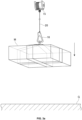
- FIG. 1 shows a perspective view schematically indicating the unmanned aerial vehicle 1 according to an embodiment of the present invention
- FIG. 2 shows a block diagram indicating the functions of the unmanned aerial vehicle 1.
- an "unmanned aerial vehicle” means an aerial vehicle that can be remotely operated, or is capable to fly autonomously, without a physical human presence within or on the aerial vehicle.
- the unmanned aerial vehicle 1 is, for example, a multicopter having a plurality of rotary wings.
- the unmanned aerial vehicle 1 includes a main body 10, six arms 11 extending outward from the main body 10, six supports 12 provided at outer ends of the respective six arms, and six rotary wings 13 provided on each of the supports 12.
- the rotary wings 13 are provided on the main body 10 via the arms 11 and the supports 12.
- the unmanned aerial vehicle 1 may further include a winch 15, a hook 16 and a wire 20.
- the support 12 rotatably supports the rotary wing 13.
- the support 12 accommodates a drive source for providing a rotational driving force to the rotary wing 13.
- the drive source is, for example, a motor 12a which will be described later.
- the rotary wing 13 is constructed and arranged so as to provide thrust to the unmanned aerial vehicle 1 during rotation.
- the unmanned aerial vehicle 1 suspends an object M with the wire 20.
- the object M suspended from the unmanned aerial vehicle 1 is any object that can be suspended by the unmanned aerial vehicle 1.
- the object M is, for example, a camera, lighting device, speaker, microphone, sensor, fire extinguishing device, a cargo and other objects.
- One end of the wire 20 is attached to the winch 15, and the other end thereof is attached to the hook 16.
- the wire 20 is guided from the winch 15 to the hook 16 via a guide member provided on the lower surface of the winch 15.
- the wire 20 may be a single wire or a twisted wire made of a metal material, synthetic resin material or other materials. Suitable wire 20 is selected depending on the weight of the object M to be suspended, the environment of use or other factors. The wire 20 is desirably flexible enough to be routed from the winch 15 through the guide member to the hook 16.
- the winch 15 has a pair of plate-like flanges 15a and a spool 15b provided between the pair of flanges 15a.
- the wire 20 is wound on the outer peripheral surface of the spool 15b of the winch 15.
- the spool 15b is supported by a pair of flanges 15a so as to be rotatable around a rotation axis.
- the winch 15 is driven, the spool 15b rotates in the forward or backward direction around the rotation axis.
- the wire is wound on the spool 15b.
- the driving power for driving the winch 15 may be supplied from a battery housed in the main body 10.
- the winch 15 may be unwound and wound according to a predetermined algorithm or under instructions from a remote operator.
- the hook 16 is configured to be capable of holding the object M.
- the hook 16 may include a hook body 16a and a movable member 16b that is rotatable relative to the hook body 16a around an axis 16c.
- the movable member 16b can take either a closed posture in which a closed loop is made by the hook body 16a and the movable member 16b as a result of the axis 16c of the movable member 16 and the opposite end coming in contact with the hook body 16a, or an open posture in which the axis 16c of the movable member 16 and the opposite end are separated from the hook body 16a.
- the movable member 16b may be controlled to take a closed posture when the hook 16 holds a cargo M, and an open posture when the cargo M is released from the hook 16.
- the movable member 16b may maintain the closed posture when the cargo M is held by the hook 16 and a certain load or more is applied to the movable member 16b as shown in FIG. 1 , and may be automatically switched from the closed posture to the open posture when the load applied to the movable member 16b becomes less than a predetermined value or when the load applied to the movable member 16b is lost.
- Automatic release hooks are generally known in the art, which are configured to switch the movable member to an open posture to release a cargo when the load is detected to be less than a certain value.
- the automatic release hook is also referred to as a no-load release hook or an automatic cargo loading hook.
- Such automatic release hooks are disclosed in Japanese Patent Application Publication No. S61-257889 , Japanese Patent Application Publication 2000-335870 and Japanese Patent Application Publication No. 2002-128455 .
- These automatic release hooks can be used as the hooks 16.
- the hook 16 may be a hook which is locked to prevent the cargo M from coming off when the cargo is held, and is manually unlocked when the cargo M is unloaded.
- a type of hook that is manually unlocked for example, a carabiner hook can be used.
- the unmanned aerial vehicle 1 includes a controller 50, the motor 12a for outputting a rotational driving force to the rotary wing 13, a motor 12b for outputting a rotational driving force to the winch 15, a sensor 14 and the winch 15.
- the controller 50 includes a computer processor 51, a memory 52 and a storage 53.
- the computer processor 51 is an arithmetic device that loads a flight control program defining a flight control algorithm from the storage 53 or other storage into the memory 52, and executes instructions contained in the loaded flight control program.
- the computer processor 51 can execute various programs related to the realization of the functions of the unmanned aerial vehicle 1.
- the controller 50 may be configured to control the rotational speed of the motor 12a and the motor 12b by outputting a PWM signal to the motor 12a and the motor 12b.
- the sensor 14 is a tension sensor that detects tension on the wire 20.
- a strain gauge may be used as the sensor 14.
- the unmanned aerial vehicle 1 may include a gyro sensor, acceleration sensor, geomagnetic sensor, barometric pressure sensor and various other sensors. These sensors are connected to the controller 50 as necessary.
- the controller 50, the motor 12b, the sensor 14, a communication device and a battery may be accommodated in the main body 10.
- the unmanned aerial vehicle 1 may include communication devices, batteries and various other devices necessary for its own operation. These components are connected to the controller 50 as necessary.
- the controller 50 may be configured to control the attitude and position of the unmanned aerial vehicle 1 by controlling the rotational speed of the rotary wing 13 according to a flight control algorithm based on detection information of various sensors provided in the unmanned aerial vehicle 1.
- the storage 53 stores a first threshold value S1 for restricting the backward rotation of the spool 15b and a second threshold value S2 for restricting the forward rotation of the spool 15b.
- the controller 50 can restrict the rotation of the spool 15b, comparing the tension of the wire 20 detected by the sensor 14 with the first and the second threshold values. In one embodiment, the controller 50 controls the rotation of the motor 12b so that the spool 15b does not rotate in the backward direction when the tension of the wire 20 is less than or equal to the first threshold value. As a result, when the tension of the wire 20 is equal to or less than the first threshold value, the wire 20 is not unwound.
- the controller 50 may drive the motor 12b such that the spool 15b rotates in the backward direction.
- the first threshold value S1 is supposed to be greater than the gravitational force m1 acting on the hook 16, that is, m1 ⁇ S1.
- the first threshold value is supposed to be less than the sum (m1+m2) of the gravitational force m1 acting on the hook 16 and the gravitational force m2 acting on the cargo M to be transported, that is, S1 ⁇ (m1+m2.)
- S1 ⁇ S1 ⁇ (m1+m2) is used.
- the first threshold value S1 and the second threshold value S2 may be changed by an operator of the unmanned aerial vehicle 1 or an operator involved in the transportation of the cargo M. For example, when instead of the hook 16, another hook is attached to the wire 20, the values of the first threshold value S1 and/or the second threshold value S2 may be changed according to the weight of the new hook. Further, the first threshold value S1 may be changed according to the weight of the cargo M to be transported.
- the controller 50 controls the rotation of the motor 12b so that the spool 15b does not rotate in the forward direction when the tension of the wire 20 is equal to or less than the second threshold value.
- the controller 50 can drive the motor 12b so that the spool 15b rotates in the forward direction.
- the second threshold value is supposed to be less than the first threshold value and less than the gravitational force m1 acting on the hook 16.
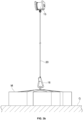
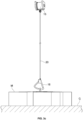
- FIGs. 3a to 3d a method of unloading the cargo M from the unmanned aerial vehicle 1 will be described.
- FIGs. 3a to 3d it is assumed that the unmanned aerial vehicle 1 carrying the cargo M has reached the skies over the destination to unload the cargo M there.
- the rotation of the motor 12b is controlled to rotate the spool 15b in the backward direction, and the wire 20 is unwound from the spool 15b. Since the cargo M is held by the wire 20 via the hook 16, the cargo M can be lowered from the sky toward the ground by unwinding the wire 20.
- the backward rotation of the spool 15b may be controlled under instructions from the operator, or may be controlled automatically on the basis of the control of the controller 50 when detecting that the spool 15b has reached the skies over the destination (not under instructions from the operator.)
- the backward rotation of the motor 12b is prohibited when the tension T of the wire 20 is equal to or less than the first threshold value S1.
- the tension T exerted on the wire 20 is equal to (m1+m2) or greater than (m1+m2) by the gravitational force exerted on the wire 20, that is, (m1+m2) ⁇ T holds.
- the tension T acting on the wire 20 becomes greater than the first threshold value S1 (S1 ⁇ T.) Accordingly, the backward rotation of the spool 15b is not restricted while the cargo M is lowered from the sky toward the ground G. Therefore, the cargo M can be smoothly lowered from the sky to the ground G.
- the cargo M reaches the ground G as shown in FIG. 3b .
- the tension T exerted on the wire 20 changes. More specifically, since the cargo M is supported upward by the ground G, the tension T exerted on the wire 20 becomes smaller than before the cargo M reaches the ground G.
- the cargo M is released from the hook 16 by manipulation of an operator on the ground G as shown in FIG. 3c , or automatically if the hook 16 is an automatic release hook.
- the tension T of the wire 20 becomes substantially equal to the gravitational force m1 acting on the hook 16, that is, T ⁇ m1 holds.
- the tension T acting on the wire 20 becomes less than the first threshold value S1 (T ⁇ S1,) and therefore, after the cargo M is released from the hook 16, the wire 20 is not further unwound. It is thus possible to prevent the wire 20 from loosening when the cargo M is released.
- the tension T acting on the wire 20 becomes substantially equal to m1, so that the controller 50 can detect that the cargo M is released from the hook 16 based on the detection signal from the sensor 14. For example, the controller 50 can determine that the cargo M has been released from the hook 16 when the tension detected by the sensor 14 becomes less than a predetermined threshold value.
- the controller 50 may drive the motor 12b in the forward direction when determining that the cargo M has been released from the hook 16.
- the hook 16 from which the cargo M is released can be retrieved by driving the motor 12b in the forward direction after the cargo M is released. For example, as shown in FIG. 3d , after the cargo M is released from the hook 16, the wire 20 is wound onto the spool 15b.
- the wire 20 may be wound up until the hook 16 rises to a position where the flight of the unmanned aerial vehicle 1 is not hindered.
- the tension T exerted on the wire 20 becomes substantially equal to the gravitational force m1 acting on the hook 16 as described above. Therefore, by making the second threshold value S2 less than the gravitational force m1 acting on the hook 16 (namely, by letting S2 ⁇ m1,) the tension T acting on the wire 20 becomes greater than the second threshold value S2 (S2 ⁇ T,) so that the forward rotation of the spool 15b is not restricted during the winding of the wire 20 after the release of the cargo M. As a result, the wire 20 can be smoothly wound up until the hook 16 rises to a predetermined position.
- the tension T of the wire 20 becomes equal to or less than the first threshold value S1
- the backward rotation of the spool 15b is restricted (i.e., the backward rotation is prohibited,) and when the tension T becomes equal to or less than the second threshold value S2, the forward rotation of the spool 15b is restricted (i.e., the forward rotation is prohibited.)
- the second threshold value S2 is less than the first threshold value S1 and the gravitational force m1 acting on the hook 16, respectively.
- the second threshold value S2 for restricting the forward rotation less than the gravitational force m1 acting on the hook 16
- the winding of the wire 20 after the release of the cargo M can be smoothly performed without restricting the forward rotation of the spool 15b. If the second threshold value S2 is set to a value equal to or greater than the gravitational force m1 acting on the hook 16, the tension T acting on the wire 20 after the release of the cargo M is the gravitational force m1 acting on the hook 16, so that the tension T becomes less than the second threshold value S2, which restricts the winding of the spool 15b.
- the wire 20 cannot be retrieved.
- the wire 20 can be retrieved by making the second threshold value S2 less than the gravitational force m1 acting on the hook 16.
- the first threshold value S1 is greater than the gravitational force m1 acting on the hook 16.
- the tension T acting on the wire 20 can be made less than the first threshold value S1. Therefore, after the release of the cargo M from the hook 16, unnecessary unwinding of the wire 20 can be prevented by prohibiting the backward rotation of the spool 15b. This can prevent the wire 20 from loosening when the cargo M is released. If the first threshold value S1 is set to a value less than the gravitational force m1 acting on the hook 16, the wire 20 continues to be unwound as the backward rotation of the spool 15b is not restricted even after the cargo M is grounded.
- the first threshold value S1 is set to a value less than the gravitational force m1 acting on the hook 16, the amount of the wire 20 unwound after the cargo M is grounded becomes greater than that in the embodiment of the present invention in which the first threshold value S1 is set to a value greater than the gravitational force m1 acting on the hook 16, which makes the line become easier to slack off.
- the first threshold value S1 is less than the sum of the gravitational force m1 acting on the hook 16 and the gravitational force m2 acting on the cargo M.
- the tension T acting on the wire 20 can be made greater than the first threshold value S1 when the cargo M is descended from the sky toward the ground G, so that the cargo M can be smoothly descended to the ground G without restricting the backward rotation of the spool 15b.
Landscapes
- Engineering & Computer Science (AREA)
- Aviation & Aerospace Engineering (AREA)
- Mechanical Engineering (AREA)
- Remote Sensing (AREA)
- Forklifts And Lifting Vehicles (AREA)
- Load-Engaging Elements For Cranes (AREA)
- Control Of Position, Course, Altitude, Or Attitude Of Moving Bodies (AREA)
Claims (1)
- Unbemanntes Luftfahrzeug (1), umfassend:einen Hauptkörper (10);eine Vielzahl von Drehflügeln (13), die auf dem Hauptkörper bereitgestellt ist;einen Draht (20) zum Abhängen eines Gegenstands von dem Hauptkörper;einen Haken (16), der an dem Draht (20) befestigt ist;einen Sensor (14) zum Erfassen der Spannung des Drahts (20);eine Seilwinde (15) zur drehbaren Lagerung einer Spule (15b), auf die der Draht in Vorwärts- und Rückwärtsrichtung gewickelt wird, wobei der Draht (20) bei Drehung der Spule (15b) in die Vorwärtsrichtung aufgewickelt wird, und der Draht (20) bei Drehung der Spule (15b) in die Rückwärtsrichtung abgewickelt wird;einen Motor (12b) zum Drehen der Spule (15b);einen Speicher (53) zum Speichern eines ersten Schwellenwerts S1 zum Begrenzen der Rückwärtsdrehung der Spule und eines zweiten Schwellenwerts S2 zum Begrenzen der Vorwärtsdrehung der Spule;
undeinen Controller (50), der zum Steuern des Motors (12b) konfiguriert ist und die Rückwärtsdrehung der Spule (15b) begrenzt, wenn die Spannung des Drahts (20) unter den ersten Schwellenwert S1 fällt;dadurch gekennzeichnet, dass der Controller (50) weiter konfiguriert ist, um (i) zu bestimmen, ob eine Ladung (M) von dem Haken (16) gelöst wurde und dann den Motor (12b) in Vorwärtsrichtung antreibt, wenn bestimmt wird, dass die Ladung (M) von dem Hakten (16) gelöst wurde, und konfiguriert ist, um (ii) beim Aufwickeln des Drahts (20) nach Freigabe der Ladung (M) die Vorwärtsdrehung der Spule (15b) zu begrenzen, wenn die Spannung des Drahts (20) unter den ersten Schwellenwert S1 fällt und gleich oder geringer als der zweite Schwellenwert S2 ist, der geringer als eine auf den Haken (16) wirkende Schwerkraft ist;wobei die Ungleichheit von S2 < m1 < S1 < (m1 + m2) verwendet wird, um den ersten Schwellenwert S1 und den zweiten Schwellenwert S2 zu bestimmen, wobei m1 als die auf den Haken wirkende Schwerkraft definiert ist und m2 als die auf die Ladung (M) wirkende Schwerkraft definiert ist.
Applications Claiming Priority (1)
| Application Number | Priority Date | Filing Date | Title |
|---|---|---|---|
| JP2018246909A JP7053450B2 (ja) | 2018-12-28 | 2018-12-28 | 無人飛行体 |
Publications (2)
| Publication Number | Publication Date |
|---|---|
| EP3674213A1 EP3674213A1 (de) | 2020-07-01 |
| EP3674213B1 true EP3674213B1 (de) | 2024-12-04 |
Family
ID=69024196
Family Applications (1)
| Application Number | Title | Priority Date | Filing Date |
|---|---|---|---|
| EP19219659.0A Active EP3674213B1 (de) | 2018-12-28 | 2019-12-24 | Unbemanntes luftfahrzeug zum transport einer nutzlast |
Country Status (4)
| Country | Link |
|---|---|
| US (1) | US11440658B2 (de) |
| EP (1) | EP3674213B1 (de) |
| JP (1) | JP7053450B2 (de) |
| CN (1) | CN111498112B (de) |
Families Citing this family (19)
| Publication number | Priority date | Publication date | Assignee | Title |
|---|---|---|---|---|
| US11401034B2 (en) * | 2018-02-28 | 2022-08-02 | Walmart Apollo, Llc | Drone delivery system having a single use lowering line |
| US12065225B2 (en) * | 2018-05-02 | 2024-08-20 | Modern Technology Solutions, Inc. | Rapid aerial extraction systems |
| WO2021155336A1 (en) * | 2020-01-31 | 2021-08-05 | Unmanned Systems Operations Group, Inc. | Multiple cargo carrying delivery system for an unmanned system and method of use |
| US11548636B2 (en) * | 2020-06-09 | 2023-01-10 | Aurora Flight Sciences Corporation, a subsidiary of The Boeing Company | Passive-release, snap-fit coupling devices for suspended payload containers of aircrafts |
| JP6972447B1 (ja) * | 2020-09-01 | 2021-11-24 | 株式会社Acsl | 荷物連結装置、及び、無人航空機 |
| CN112776984A (zh) * | 2021-03-15 | 2021-05-11 | 国网新疆电力有限公司巴州供电公司 | 无人机定点投掷装置 |
| WO2022239141A1 (ja) * | 2021-05-12 | 2022-11-17 | 株式会社エアロネクスト | 懸下部材の位置制限装置 |
| US20240239485A1 (en) * | 2021-09-17 | 2024-07-18 | Jetzero, Inc. | Blended wing body aircraft with a fuel cell and method of use |
| US12103682B2 (en) * | 2021-12-17 | 2024-10-01 | Wing Aviation, Llc | Package coupling apparatus with strap and hanger for securing a package to a UAV and method of securing a package for delivery |
| US12539967B2 (en) * | 2022-04-14 | 2026-02-03 | Aero Velocity Inc. | Unmanned aerial vehicle delivery systems |
| TWI856613B (zh) * | 2022-04-20 | 2024-09-21 | 奧榮科技股份有限公司 | 無人飛行載具之載物掛勾下放與收回的控制裝置及方法 |
| WO2023219981A1 (en) * | 2022-05-11 | 2023-11-16 | Signode Industrial Group Llc | Methods of using straps for aerial transport of packages |
| KR102666443B1 (ko) * | 2022-05-25 | 2024-05-24 | 한서대학교 산학협력단 | 제초 운반용 드론 및 이의 운용 방법 |
| US11987351B2 (en) * | 2022-08-10 | 2024-05-21 | Textron Innovations Inc. | Tow line tension management systems for aircraft |
| US12434837B2 (en) * | 2022-09-12 | 2025-10-07 | Textron Innovations Inc. | Tailsitter with pivoting pole for controlling external loads |
| US12377995B2 (en) * | 2022-11-22 | 2025-08-05 | Embraer S.A. | Aircraft tail mounted fuel cell power train and thermal management systems |
| TR2023007843A1 (tr) * | 2023-07-05 | 2025-01-21 | Tusas Tuerk Havacilik Ve Uzay Sanayii Anonim Sirketi | Bir faydalı yük taşıma sistemi |
| CN117553755B (zh) * | 2024-01-09 | 2024-04-23 | 武汉能钠智能装备技术股份有限公司四川省成都市分公司 | 一种无人机侦测系统及控制方法 |
| US12119626B1 (en) * | 2024-03-09 | 2024-10-15 | Henry Hardy Perritt, Jr. | System and method for lifting lines over a support using a drone |
Citations (3)
| Publication number | Priority date | Publication date | Assignee | Title |
|---|---|---|---|---|
| EP0850834A1 (de) * | 1996-12-23 | 1998-07-01 | The Boeing Company | Fluggastsitz, drehbar und veränderbar in ein Bett |
| EP3378770A1 (de) * | 2017-03-20 | 2018-09-26 | Optimares S.p.A. | Sitzanordnung, insbesondere für luftfahrzeuge |
| DE102020105072A1 (de) * | 2020-02-26 | 2021-08-26 | Recaro Aircraft Seating Gmbh & Co. Kg | Flugzeugsitzanordnung |
Family Cites Families (20)
| Publication number | Priority date | Publication date | Assignee | Title |
|---|---|---|---|---|
| JPS5926896A (ja) * | 1982-08-06 | 1984-02-13 | 神鋼電機株式会社 | オ−トテンシヨンウインチの制御方法 |
| JPS61257889A (ja) | 1985-05-09 | 1986-11-15 | 有限会社 鳥島工業 | 自動解除フツク |
| JPH09278382A (ja) * | 1996-04-16 | 1997-10-28 | Aichi Corp | クレーンのワイヤ乱巻防止装置 |
| JP2000335870A (ja) | 1999-05-27 | 2000-12-05 | Sankei Tekkosho:Kk | 自動荷役フック並びにロック機構 |
| JP2002128455A (ja) | 2000-10-20 | 2002-05-09 | Nec Eng Ltd | 無負荷釈放機構を備えた荷物吊り下げフック |
| WO2008130402A2 (en) * | 2007-04-19 | 2008-10-30 | Sikorsky Aircraft Corporation | Winch system for vtol aircraft |
| JP2013079034A (ja) * | 2011-10-05 | 2013-05-02 | Zero:Kk | 空撮用回転翼機 |
| US9174733B1 (en) * | 2014-08-28 | 2015-11-03 | Google Inc. | Payload-release device and operation thereof |
| US9676481B1 (en) * | 2015-03-27 | 2017-06-13 | Amazon Technologies, Inc. | Tether compensated airborne delivery |
| US10071804B1 (en) * | 2015-09-28 | 2018-09-11 | Amazon Technologies, Inc. | Delivery drop rate modulation |
| EP4032820A1 (de) * | 2015-10-17 | 2022-07-27 | Wing Aviation LLC | Aerodynamische tragetasche und verfahren zur herstellung einer aerodynamischen tragetasche |
| KR101707130B1 (ko) * | 2015-10-20 | 2017-02-15 | 씨제이대한통운 (주) | 비행유닛 기반 화물낙하장치 및 시스템 |
| US20180312247A1 (en) * | 2015-11-06 | 2018-11-01 | Prodrone Co., Ltd. | Carrying device |
| JP6393887B2 (ja) | 2015-11-06 | 2018-09-26 | 株式会社プロドローン | 運搬装置および運搬方法 |
| AU2017266620A1 (en) * | 2016-05-16 | 2018-12-06 | Hatch Ltd. | Apparatus connecting a water sample bottle to an Unmanned Aerial Vehicle (UAV) in order to collect water samples from below the surface of a water body |
| US10414488B2 (en) * | 2016-09-09 | 2019-09-17 | Wing Aviation Llc | Methods and systems for damping oscillations of a payload |
| US10384782B2 (en) * | 2017-02-28 | 2019-08-20 | Lockheed Martin Corporation | Airborne payload control system |
| EP3613700A4 (de) * | 2017-04-17 | 2021-01-13 | Globeride, Inc. | Elektrische hebemaschine sowie steuerungsvorrichtung und steuerungsverfahren dafür |
| CN207773482U (zh) * | 2017-12-27 | 2018-08-28 | 深圳市中联讯科技有限公司 | 一种无人运输飞行器 |
| CN108674661A (zh) * | 2018-05-18 | 2018-10-19 | 智飞智能装备科技东台有限公司 | 一种用于无人机的安全投放系统 |
-
2018
- 2018-12-28 JP JP2018246909A patent/JP7053450B2/ja active Active
-
2019
- 2019-12-24 EP EP19219659.0A patent/EP3674213B1/de active Active
- 2019-12-25 CN CN201911354674.0A patent/CN111498112B/zh active Active
- 2019-12-26 US US16/727,745 patent/US11440658B2/en active Active
Patent Citations (3)
| Publication number | Priority date | Publication date | Assignee | Title |
|---|---|---|---|---|
| EP0850834A1 (de) * | 1996-12-23 | 1998-07-01 | The Boeing Company | Fluggastsitz, drehbar und veränderbar in ein Bett |
| EP3378770A1 (de) * | 2017-03-20 | 2018-09-26 | Optimares S.p.A. | Sitzanordnung, insbesondere für luftfahrzeuge |
| DE102020105072A1 (de) * | 2020-02-26 | 2021-08-26 | Recaro Aircraft Seating Gmbh & Co. Kg | Flugzeugsitzanordnung |
Also Published As
| Publication number | Publication date |
|---|---|
| US20200207471A1 (en) | 2020-07-02 |
| CN111498112B (zh) | 2023-08-22 |
| US11440658B2 (en) | 2022-09-13 |
| CN111498112A (zh) | 2020-08-07 |
| EP3674213A1 (de) | 2020-07-01 |
| JP7053450B2 (ja) | 2022-04-12 |
| JP2020104771A (ja) | 2020-07-09 |
Similar Documents
| Publication | Publication Date | Title |
|---|---|---|
| US11440658B2 (en) | Unmanned aerial vehicle with a controller for controlling the backward and forward rotation of a spooling winch | |
| JP7084892B2 (ja) | 無人飛行体 | |
| JP6393888B2 (ja) | 運搬装置 | |
| US11535496B2 (en) | Device for stabilizing a hoisted object | |
| JP6393887B2 (ja) | 運搬装置および運搬方法 | |
| US11407511B1 (en) | Delivery drop platforms, tethers, and stabilization | |
| US10071804B1 (en) | Delivery drop rate modulation | |
| EP3929081B1 (de) | Unbemanntes luftfahrzeug, steuerungssystem für luftfahrzeug und transportverfahren | |
| CN114423703A (zh) | 提升机和可展开设备、装置、系统和方法 | |
| EP3889042B1 (de) | Unbemanntes luftfahrzeug, vorrichtung zum absenken einer last und verfahren zum transportieren einer last | |
| US20170197718A1 (en) | Tether compensated airborne delivery | |
| KR102308242B1 (ko) | 화물수송 드론용 윈치 시스템 및 이의 운용방법 | |
| US12054256B2 (en) | UAV with upper door including winch and method of operation | |
| US11572259B2 (en) | System and method for aerial cord release mechanisms | |
| WO2024015732A1 (en) | Slotted receptacle for payload handle to secure payload within a uav | |
| JPWO2021095249A1 (ja) | 無人飛行体システム、制御装置及び制御方法 | |
| EP4529519A1 (de) | Intelligente frachtraumtür(en) für ein uav | |
| JP2001354196A (ja) | 重量物空中搬送装置 | |
| JP2022046458A (ja) | 飛行体、吊り荷制御装置、方法 | |
| RU213951U1 (ru) | Устройство развёртываемого оборудования для подъёма груза | |
| JP2023019396A (ja) | 飛行体及び制御プログラム | |
| JP2020132347A (ja) | 介錯ロープ装置 |
Legal Events
| Date | Code | Title | Description |
|---|---|---|---|
| PUAI | Public reference made under article 153(3) epc to a published international application that has entered the european phase |
Free format text: ORIGINAL CODE: 0009012 |
|
| STAA | Information on the status of an ep patent application or granted ep patent |
Free format text: STATUS: REQUEST FOR EXAMINATION WAS MADE |
|
| 17P | Request for examination filed |
Effective date: 20191224 |
|
| AK | Designated contracting states |
Kind code of ref document: A1 Designated state(s): AL AT BE BG CH CY CZ DE DK EE ES FI FR GB GR HR HU IE IS IT LI LT LU LV MC MK MT NL NO PL PT RO RS SE SI SK SM TR |
|
| AX | Request for extension of the european patent |
Extension state: BA ME |
|
| STAA | Information on the status of an ep patent application or granted ep patent |
Free format text: STATUS: EXAMINATION IS IN PROGRESS |
|
| 17Q | First examination report despatched |
Effective date: 20220309 |
|
| P01 | Opt-out of the competence of the unified patent court (upc) registered |
Effective date: 20230511 |
|
| GRAP | Despatch of communication of intention to grant a patent |
Free format text: ORIGINAL CODE: EPIDOSNIGR1 |
|
| STAA | Information on the status of an ep patent application or granted ep patent |
Free format text: STATUS: GRANT OF PATENT IS INTENDED |
|
| INTG | Intention to grant announced |
Effective date: 20240731 |
|
| GRAS | Grant fee paid |
Free format text: ORIGINAL CODE: EPIDOSNIGR3 |
|
| GRAA | (expected) grant |
Free format text: ORIGINAL CODE: 0009210 |
|
| STAA | Information on the status of an ep patent application or granted ep patent |
Free format text: STATUS: THE PATENT HAS BEEN GRANTED |
|
| AK | Designated contracting states |
Kind code of ref document: B1 Designated state(s): AL AT BE BG CH CY CZ DE DK EE ES FI FR GB GR HR HU IE IS IT LI LT LU LV MC MK MT NL NO PL PT RO RS SE SI SK SM TR |
|
| REG | Reference to a national code |
Ref country code: GB Ref legal event code: FG4D |
|
| REG | Reference to a national code |
Ref country code: CH Ref legal event code: EP |
|
| REG | Reference to a national code |
Ref country code: DE Ref legal event code: R096 Ref document number: 602019062892 Country of ref document: DE |
|
| REG | Reference to a national code |
Ref country code: IE Ref legal event code: FG4D |
|
| REG | Reference to a national code |
Ref country code: LT Ref legal event code: MG9D |
|
| REG | Reference to a national code |
Ref country code: NL Ref legal event code: MP Effective date: 20241204 |
|
| PG25 | Lapsed in a contracting state [announced via postgrant information from national office to epo] |
Ref country code: HR Free format text: LAPSE BECAUSE OF FAILURE TO SUBMIT A TRANSLATION OF THE DESCRIPTION OR TO PAY THE FEE WITHIN THE PRESCRIBED TIME-LIMIT Effective date: 20241204 |
|
| PG25 | Lapsed in a contracting state [announced via postgrant information from national office to epo] |
Ref country code: FI Free format text: LAPSE BECAUSE OF FAILURE TO SUBMIT A TRANSLATION OF THE DESCRIPTION OR TO PAY THE FEE WITHIN THE PRESCRIBED TIME-LIMIT Effective date: 20241204 |
|
| PG25 | Lapsed in a contracting state [announced via postgrant information from national office to epo] |
Ref country code: BG Free format text: LAPSE BECAUSE OF FAILURE TO SUBMIT A TRANSLATION OF THE DESCRIPTION OR TO PAY THE FEE WITHIN THE PRESCRIBED TIME-LIMIT Effective date: 20241204 |
|
| PG25 | Lapsed in a contracting state [announced via postgrant information from national office to epo] |
Ref country code: ES Free format text: LAPSE BECAUSE OF FAILURE TO SUBMIT A TRANSLATION OF THE DESCRIPTION OR TO PAY THE FEE WITHIN THE PRESCRIBED TIME-LIMIT Effective date: 20241204 |
|
| PG25 | Lapsed in a contracting state [announced via postgrant information from national office to epo] |
Ref country code: NO Free format text: LAPSE BECAUSE OF FAILURE TO SUBMIT A TRANSLATION OF THE DESCRIPTION OR TO PAY THE FEE WITHIN THE PRESCRIBED TIME-LIMIT Effective date: 20250304 |
|
| PG25 | Lapsed in a contracting state [announced via postgrant information from national office to epo] |
Ref country code: LV Free format text: LAPSE BECAUSE OF FAILURE TO SUBMIT A TRANSLATION OF THE DESCRIPTION OR TO PAY THE FEE WITHIN THE PRESCRIBED TIME-LIMIT Effective date: 20241204 Ref country code: GR Free format text: LAPSE BECAUSE OF FAILURE TO SUBMIT A TRANSLATION OF THE DESCRIPTION OR TO PAY THE FEE WITHIN THE PRESCRIBED TIME-LIMIT Effective date: 20250305 |
|
| PG25 | Lapsed in a contracting state [announced via postgrant information from national office to epo] |
Ref country code: RS Free format text: LAPSE BECAUSE OF FAILURE TO SUBMIT A TRANSLATION OF THE DESCRIPTION OR TO PAY THE FEE WITHIN THE PRESCRIBED TIME-LIMIT Effective date: 20250304 |
|
| PG25 | Lapsed in a contracting state [announced via postgrant information from national office to epo] |
Ref country code: NL Free format text: LAPSE BECAUSE OF FAILURE TO SUBMIT A TRANSLATION OF THE DESCRIPTION OR TO PAY THE FEE WITHIN THE PRESCRIBED TIME-LIMIT Effective date: 20241204 |
|
| REG | Reference to a national code |
Ref country code: AT Ref legal event code: MK05 Ref document number: 1747935 Country of ref document: AT Kind code of ref document: T Effective date: 20241204 |
|
| PG25 | Lapsed in a contracting state [announced via postgrant information from national office to epo] |
Ref country code: SM Free format text: LAPSE BECAUSE OF FAILURE TO SUBMIT A TRANSLATION OF THE DESCRIPTION OR TO PAY THE FEE WITHIN THE PRESCRIBED TIME-LIMIT Effective date: 20241204 |
|
| PG25 | Lapsed in a contracting state [announced via postgrant information from national office to epo] |
Ref country code: PL Free format text: LAPSE BECAUSE OF FAILURE TO SUBMIT A TRANSLATION OF THE DESCRIPTION OR TO PAY THE FEE WITHIN THE PRESCRIBED TIME-LIMIT Effective date: 20241204 |
|
| PG25 | Lapsed in a contracting state [announced via postgrant information from national office to epo] |
Ref country code: IS Free format text: LAPSE BECAUSE OF FAILURE TO SUBMIT A TRANSLATION OF THE DESCRIPTION OR TO PAY THE FEE WITHIN THE PRESCRIBED TIME-LIMIT Effective date: 20250404 |
|
| PG25 | Lapsed in a contracting state [announced via postgrant information from national office to epo] |
Ref country code: PT Free format text: LAPSE BECAUSE OF FAILURE TO SUBMIT A TRANSLATION OF THE DESCRIPTION OR TO PAY THE FEE WITHIN THE PRESCRIBED TIME-LIMIT Effective date: 20250404 |
|
| PG25 | Lapsed in a contracting state [announced via postgrant information from national office to epo] |
Ref country code: EE Free format text: LAPSE BECAUSE OF FAILURE TO SUBMIT A TRANSLATION OF THE DESCRIPTION OR TO PAY THE FEE WITHIN THE PRESCRIBED TIME-LIMIT Effective date: 20241204 |
|
| PG25 | Lapsed in a contracting state [announced via postgrant information from national office to epo] |
Ref country code: AT Free format text: LAPSE BECAUSE OF FAILURE TO SUBMIT A TRANSLATION OF THE DESCRIPTION OR TO PAY THE FEE WITHIN THE PRESCRIBED TIME-LIMIT Effective date: 20241204 Ref country code: RO Free format text: LAPSE BECAUSE OF FAILURE TO SUBMIT A TRANSLATION OF THE DESCRIPTION OR TO PAY THE FEE WITHIN THE PRESCRIBED TIME-LIMIT Effective date: 20241204 |
|
| PG25 | Lapsed in a contracting state [announced via postgrant information from national office to epo] |
Ref country code: SK Free format text: LAPSE BECAUSE OF FAILURE TO SUBMIT A TRANSLATION OF THE DESCRIPTION OR TO PAY THE FEE WITHIN THE PRESCRIBED TIME-LIMIT Effective date: 20241204 |
|
| PG25 | Lapsed in a contracting state [announced via postgrant information from national office to epo] |
Ref country code: CZ Free format text: LAPSE BECAUSE OF FAILURE TO SUBMIT A TRANSLATION OF THE DESCRIPTION OR TO PAY THE FEE WITHIN THE PRESCRIBED TIME-LIMIT Effective date: 20241204 |
|
| PG25 | Lapsed in a contracting state [announced via postgrant information from national office to epo] |
Ref country code: IT Free format text: LAPSE BECAUSE OF FAILURE TO SUBMIT A TRANSLATION OF THE DESCRIPTION OR TO PAY THE FEE WITHIN THE PRESCRIBED TIME-LIMIT Effective date: 20241204 |
|
| REG | Reference to a national code |
Ref country code: CH Ref legal event code: PL |
|
| PG25 | Lapsed in a contracting state [announced via postgrant information from national office to epo] |
Ref country code: LU Free format text: LAPSE BECAUSE OF NON-PAYMENT OF DUE FEES Effective date: 20241224 |
|
| REG | Reference to a national code |
Ref country code: DE Ref legal event code: R097 Ref document number: 602019062892 Country of ref document: DE |
|
| PG25 | Lapsed in a contracting state [announced via postgrant information from national office to epo] |
Ref country code: SE Free format text: LAPSE BECAUSE OF FAILURE TO SUBMIT A TRANSLATION OF THE DESCRIPTION OR TO PAY THE FEE WITHIN THE PRESCRIBED TIME-LIMIT Effective date: 20241204 |
|
| PG25 | Lapsed in a contracting state [announced via postgrant information from national office to epo] |
Ref country code: MC Free format text: LAPSE BECAUSE OF FAILURE TO SUBMIT A TRANSLATION OF THE DESCRIPTION OR TO PAY THE FEE WITHIN THE PRESCRIBED TIME-LIMIT Effective date: 20241204 |
|
| REG | Reference to a national code |
Ref country code: BE Ref legal event code: MM Effective date: 20241231 |
|
| PG25 | Lapsed in a contracting state [announced via postgrant information from national office to epo] |
Ref country code: DK Free format text: LAPSE BECAUSE OF FAILURE TO SUBMIT A TRANSLATION OF THE DESCRIPTION OR TO PAY THE FEE WITHIN THE PRESCRIBED TIME-LIMIT Effective date: 20241204 |
|
| PLBE | No opposition filed within time limit |
Free format text: ORIGINAL CODE: 0009261 |
|
| STAA | Information on the status of an ep patent application or granted ep patent |
Free format text: STATUS: NO OPPOSITION FILED WITHIN TIME LIMIT |
|
| PG25 | Lapsed in a contracting state [announced via postgrant information from national office to epo] |
Ref country code: BE Free format text: LAPSE BECAUSE OF NON-PAYMENT OF DUE FEES Effective date: 20241231 |
|
| PG25 | Lapsed in a contracting state [announced via postgrant information from national office to epo] |
Ref country code: CH Free format text: LAPSE BECAUSE OF NON-PAYMENT OF DUE FEES Effective date: 20241231 |
|
| PG25 | Lapsed in a contracting state [announced via postgrant information from national office to epo] |
Ref country code: IE Free format text: LAPSE BECAUSE OF NON-PAYMENT OF DUE FEES Effective date: 20241224 |
|
| 26N | No opposition filed |
Effective date: 20250905 |
|
| GBPC | Gb: european patent ceased through non-payment of renewal fee |
Effective date: 20250304 |
|
| PGFP | Annual fee paid to national office [announced via postgrant information from national office to epo] |
Ref country code: DE Payment date: 20251028 Year of fee payment: 7 |
|
| PG25 | Lapsed in a contracting state [announced via postgrant information from national office to epo] |
Ref country code: GB Free format text: LAPSE BECAUSE OF NON-PAYMENT OF DUE FEES Effective date: 20250304 |
|
| PG25 | Lapsed in a contracting state [announced via postgrant information from national office to epo] |
Ref country code: FR Free format text: LAPSE BECAUSE OF NON-PAYMENT OF DUE FEES Effective date: 20250204 |
|
| PG25 | Lapsed in a contracting state [announced via postgrant information from national office to epo] |
Ref country code: CY Free format text: LAPSE BECAUSE OF FAILURE TO SUBMIT A TRANSLATION OF THE DESCRIPTION OR TO PAY THE FEE WITHIN THE PRESCRIBED TIME-LIMIT Effective date: 20241204 |