EP3674155B1 - Collision avoidance apparatus and collision avoidance method - Google Patents
Collision avoidance apparatus and collision avoidance method Download PDFInfo
- Publication number
- EP3674155B1 EP3674155B1 EP19202009.7A EP19202009A EP3674155B1 EP 3674155 B1 EP3674155 B1 EP 3674155B1 EP 19202009 A EP19202009 A EP 19202009A EP 3674155 B1 EP3674155 B1 EP 3674155B1
- Authority
- EP
- European Patent Office
- Prior art keywords
- information
- vehicle
- subject vehicle
- steering avoidance
- overlap
- Prior art date
- Legal status (The legal status is an assumption and is not a legal conclusion. Google has not performed a legal analysis and makes no representation as to the accuracy of the status listed.)
- Active
Links
- 238000000034 method Methods 0.000 title claims description 35
- 230000001133 acceleration Effects 0.000 claims description 44
- 230000004044 response Effects 0.000 claims description 14
- 238000012545 processing Methods 0.000 claims description 9
- 238000001514 detection method Methods 0.000 claims description 7
- 238000012935 Averaging Methods 0.000 claims description 6
- 230000008569 process Effects 0.000 claims description 6
- 230000005540 biological transmission Effects 0.000 description 19
- 238000013459 approach Methods 0.000 description 4
- 238000004891 communication Methods 0.000 description 4
- 230000006870 function Effects 0.000 description 4
- 238000003491 array Methods 0.000 description 3
- 108010062618 Oncogene Proteins v-rel Proteins 0.000 description 2
- 230000008859 change Effects 0.000 description 2
- 238000010586 diagram Methods 0.000 description 2
- 230000005484 gravity Effects 0.000 description 2
- 230000007246 mechanism Effects 0.000 description 2
- 230000005855 radiation Effects 0.000 description 2
- XUIMIQQOPSSXEZ-UHFFFAOYSA-N Silicon Chemical compound [Si] XUIMIQQOPSSXEZ-UHFFFAOYSA-N 0.000 description 1
- 230000003044 adaptive effect Effects 0.000 description 1
- 238000004364 calculation method Methods 0.000 description 1
- 238000013500 data storage Methods 0.000 description 1
- 230000001419 dependent effect Effects 0.000 description 1
- 238000011161 development Methods 0.000 description 1
- 238000009434 installation Methods 0.000 description 1
- 239000000463 material Substances 0.000 description 1
- 230000003287 optical effect Effects 0.000 description 1
- 238000011160 research Methods 0.000 description 1
- 230000008054 signal transmission Effects 0.000 description 1
- 229910052710 silicon Inorganic materials 0.000 description 1
- 239000010703 silicon Substances 0.000 description 1
- 239000007787 solid Substances 0.000 description 1
- 239000000758 substrate Substances 0.000 description 1
Images


Classifications
-
- B—PERFORMING OPERATIONS; TRANSPORTING
- B60—VEHICLES IN GENERAL
- B60W—CONJOINT CONTROL OF VEHICLE SUB-UNITS OF DIFFERENT TYPE OR DIFFERENT FUNCTION; CONTROL SYSTEMS SPECIALLY ADAPTED FOR HYBRID VEHICLES; ROAD VEHICLE DRIVE CONTROL SYSTEMS FOR PURPOSES NOT RELATED TO THE CONTROL OF A PARTICULAR SUB-UNIT
- B60W30/00—Purposes of road vehicle drive control systems not related to the control of a particular sub-unit, e.g. of systems using conjoint control of vehicle sub-units, or advanced driver assistance systems for ensuring comfort, stability and safety or drive control systems for propelling or retarding the vehicle
- B60W30/08—Active safety systems predicting or avoiding probable or impending collision or attempting to minimise its consequences
- B60W30/095—Predicting travel path or likelihood of collision
-
- B—PERFORMING OPERATIONS; TRANSPORTING
- B60—VEHICLES IN GENERAL
- B60W—CONJOINT CONTROL OF VEHICLE SUB-UNITS OF DIFFERENT TYPE OR DIFFERENT FUNCTION; CONTROL SYSTEMS SPECIALLY ADAPTED FOR HYBRID VEHICLES; ROAD VEHICLE DRIVE CONTROL SYSTEMS FOR PURPOSES NOT RELATED TO THE CONTROL OF A PARTICULAR SUB-UNIT
- B60W10/00—Conjoint control of vehicle sub-units of different type or different function
- B60W10/20—Conjoint control of vehicle sub-units of different type or different function including control of steering systems
-
- B—PERFORMING OPERATIONS; TRANSPORTING
- B60—VEHICLES IN GENERAL
- B60W—CONJOINT CONTROL OF VEHICLE SUB-UNITS OF DIFFERENT TYPE OR DIFFERENT FUNCTION; CONTROL SYSTEMS SPECIALLY ADAPTED FOR HYBRID VEHICLES; ROAD VEHICLE DRIVE CONTROL SYSTEMS FOR PURPOSES NOT RELATED TO THE CONTROL OF A PARTICULAR SUB-UNIT
- B60W30/00—Purposes of road vehicle drive control systems not related to the control of a particular sub-unit, e.g. of systems using conjoint control of vehicle sub-units, or advanced driver assistance systems for ensuring comfort, stability and safety or drive control systems for propelling or retarding the vehicle
- B60W30/08—Active safety systems predicting or avoiding probable or impending collision or attempting to minimise its consequences
- B60W30/09—Taking automatic action to avoid collision, e.g. braking and steering
-
- B—PERFORMING OPERATIONS; TRANSPORTING
- B60—VEHICLES IN GENERAL
- B60W—CONJOINT CONTROL OF VEHICLE SUB-UNITS OF DIFFERENT TYPE OR DIFFERENT FUNCTION; CONTROL SYSTEMS SPECIALLY ADAPTED FOR HYBRID VEHICLES; ROAD VEHICLE DRIVE CONTROL SYSTEMS FOR PURPOSES NOT RELATED TO THE CONTROL OF A PARTICULAR SUB-UNIT
- B60W30/00—Purposes of road vehicle drive control systems not related to the control of a particular sub-unit, e.g. of systems using conjoint control of vehicle sub-units, or advanced driver assistance systems for ensuring comfort, stability and safety or drive control systems for propelling or retarding the vehicle
- B60W30/08—Active safety systems predicting or avoiding probable or impending collision or attempting to minimise its consequences
- B60W30/095—Predicting travel path or likelihood of collision
- B60W30/0953—Predicting travel path or likelihood of collision the prediction being responsive to vehicle dynamic parameters
-
- B—PERFORMING OPERATIONS; TRANSPORTING
- B60—VEHICLES IN GENERAL
- B60W—CONJOINT CONTROL OF VEHICLE SUB-UNITS OF DIFFERENT TYPE OR DIFFERENT FUNCTION; CONTROL SYSTEMS SPECIALLY ADAPTED FOR HYBRID VEHICLES; ROAD VEHICLE DRIVE CONTROL SYSTEMS FOR PURPOSES NOT RELATED TO THE CONTROL OF A PARTICULAR SUB-UNIT
- B60W30/00—Purposes of road vehicle drive control systems not related to the control of a particular sub-unit, e.g. of systems using conjoint control of vehicle sub-units, or advanced driver assistance systems for ensuring comfort, stability and safety or drive control systems for propelling or retarding the vehicle
- B60W30/08—Active safety systems predicting or avoiding probable or impending collision or attempting to minimise its consequences
- B60W30/095—Predicting travel path or likelihood of collision
- B60W30/0956—Predicting travel path or likelihood of collision the prediction being responsive to traffic or environmental parameters
-
- B—PERFORMING OPERATIONS; TRANSPORTING
- B60—VEHICLES IN GENERAL
- B60W—CONJOINT CONTROL OF VEHICLE SUB-UNITS OF DIFFERENT TYPE OR DIFFERENT FUNCTION; CONTROL SYSTEMS SPECIALLY ADAPTED FOR HYBRID VEHICLES; ROAD VEHICLE DRIVE CONTROL SYSTEMS FOR PURPOSES NOT RELATED TO THE CONTROL OF A PARTICULAR SUB-UNIT
- B60W40/00—Estimation or calculation of non-directly measurable driving parameters for road vehicle drive control systems not related to the control of a particular sub unit, e.g. by using mathematical models
- B60W40/02—Estimation or calculation of non-directly measurable driving parameters for road vehicle drive control systems not related to the control of a particular sub unit, e.g. by using mathematical models related to ambient conditions
-
- B—PERFORMING OPERATIONS; TRANSPORTING
- B60—VEHICLES IN GENERAL
- B60W—CONJOINT CONTROL OF VEHICLE SUB-UNITS OF DIFFERENT TYPE OR DIFFERENT FUNCTION; CONTROL SYSTEMS SPECIALLY ADAPTED FOR HYBRID VEHICLES; ROAD VEHICLE DRIVE CONTROL SYSTEMS FOR PURPOSES NOT RELATED TO THE CONTROL OF A PARTICULAR SUB-UNIT
- B60W40/00—Estimation or calculation of non-directly measurable driving parameters for road vehicle drive control systems not related to the control of a particular sub unit, e.g. by using mathematical models
- B60W40/10—Estimation or calculation of non-directly measurable driving parameters for road vehicle drive control systems not related to the control of a particular sub unit, e.g. by using mathematical models related to vehicle motion
- B60W40/105—Speed
-
- B—PERFORMING OPERATIONS; TRANSPORTING
- B60—VEHICLES IN GENERAL
- B60W—CONJOINT CONTROL OF VEHICLE SUB-UNITS OF DIFFERENT TYPE OR DIFFERENT FUNCTION; CONTROL SYSTEMS SPECIALLY ADAPTED FOR HYBRID VEHICLES; ROAD VEHICLE DRIVE CONTROL SYSTEMS FOR PURPOSES NOT RELATED TO THE CONTROL OF A PARTICULAR SUB-UNIT
- B60W40/00—Estimation or calculation of non-directly measurable driving parameters for road vehicle drive control systems not related to the control of a particular sub unit, e.g. by using mathematical models
- B60W40/10—Estimation or calculation of non-directly measurable driving parameters for road vehicle drive control systems not related to the control of a particular sub unit, e.g. by using mathematical models related to vehicle motion
- B60W40/114—Yaw movement
-
- G—PHYSICS
- G06—COMPUTING; CALCULATING OR COUNTING
- G06V—IMAGE OR VIDEO RECOGNITION OR UNDERSTANDING
- G06V20/00—Scenes; Scene-specific elements
- G06V20/50—Context or environment of the image
- G06V20/56—Context or environment of the image exterior to a vehicle by using sensors mounted on the vehicle
- G06V20/58—Recognition of moving objects or obstacles, e.g. vehicles or pedestrians; Recognition of traffic objects, e.g. traffic signs, traffic lights or roads
- G06V20/584—Recognition of moving objects or obstacles, e.g. vehicles or pedestrians; Recognition of traffic objects, e.g. traffic signs, traffic lights or roads of vehicle lights or traffic lights
-
- G—PHYSICS
- G08—SIGNALLING
- G08G—TRAFFIC CONTROL SYSTEMS
- G08G1/00—Traffic control systems for road vehicles
- G08G1/16—Anti-collision systems
- G08G1/166—Anti-collision systems for active traffic, e.g. moving vehicles, pedestrians, bikes
-
- B60W2420/408—
-
- B—PERFORMING OPERATIONS; TRANSPORTING
- B60—VEHICLES IN GENERAL
- B60W—CONJOINT CONTROL OF VEHICLE SUB-UNITS OF DIFFERENT TYPE OR DIFFERENT FUNCTION; CONTROL SYSTEMS SPECIALLY ADAPTED FOR HYBRID VEHICLES; ROAD VEHICLE DRIVE CONTROL SYSTEMS FOR PURPOSES NOT RELATED TO THE CONTROL OF A PARTICULAR SUB-UNIT
- B60W2420/00—Indexing codes relating to the type of sensors based on the principle of their operation
- B60W2420/54—Audio sensitive means, e.g. ultrasound
-
- B—PERFORMING OPERATIONS; TRANSPORTING
- B60—VEHICLES IN GENERAL
- B60W—CONJOINT CONTROL OF VEHICLE SUB-UNITS OF DIFFERENT TYPE OR DIFFERENT FUNCTION; CONTROL SYSTEMS SPECIALLY ADAPTED FOR HYBRID VEHICLES; ROAD VEHICLE DRIVE CONTROL SYSTEMS FOR PURPOSES NOT RELATED TO THE CONTROL OF A PARTICULAR SUB-UNIT
- B60W2520/00—Input parameters relating to overall vehicle dynamics
- B60W2520/10—Longitudinal speed
-
- B—PERFORMING OPERATIONS; TRANSPORTING
- B60—VEHICLES IN GENERAL
- B60W—CONJOINT CONTROL OF VEHICLE SUB-UNITS OF DIFFERENT TYPE OR DIFFERENT FUNCTION; CONTROL SYSTEMS SPECIALLY ADAPTED FOR HYBRID VEHICLES; ROAD VEHICLE DRIVE CONTROL SYSTEMS FOR PURPOSES NOT RELATED TO THE CONTROL OF A PARTICULAR SUB-UNIT
- B60W2520/00—Input parameters relating to overall vehicle dynamics
- B60W2520/12—Lateral speed
-
- B—PERFORMING OPERATIONS; TRANSPORTING
- B60—VEHICLES IN GENERAL
- B60W—CONJOINT CONTROL OF VEHICLE SUB-UNITS OF DIFFERENT TYPE OR DIFFERENT FUNCTION; CONTROL SYSTEMS SPECIALLY ADAPTED FOR HYBRID VEHICLES; ROAD VEHICLE DRIVE CONTROL SYSTEMS FOR PURPOSES NOT RELATED TO THE CONTROL OF A PARTICULAR SUB-UNIT
- B60W2520/00—Input parameters relating to overall vehicle dynamics
- B60W2520/14—Yaw
-
- B—PERFORMING OPERATIONS; TRANSPORTING
- B60—VEHICLES IN GENERAL
- B60W—CONJOINT CONTROL OF VEHICLE SUB-UNITS OF DIFFERENT TYPE OR DIFFERENT FUNCTION; CONTROL SYSTEMS SPECIALLY ADAPTED FOR HYBRID VEHICLES; ROAD VEHICLE DRIVE CONTROL SYSTEMS FOR PURPOSES NOT RELATED TO THE CONTROL OF A PARTICULAR SUB-UNIT
- B60W2554/00—Input parameters relating to objects
- B60W2554/40—Dynamic objects, e.g. animals, windblown objects
- B60W2554/404—Characteristics
- B60W2554/4042—Longitudinal speed
-
- B—PERFORMING OPERATIONS; TRANSPORTING
- B60—VEHICLES IN GENERAL
- B60W—CONJOINT CONTROL OF VEHICLE SUB-UNITS OF DIFFERENT TYPE OR DIFFERENT FUNCTION; CONTROL SYSTEMS SPECIALLY ADAPTED FOR HYBRID VEHICLES; ROAD VEHICLE DRIVE CONTROL SYSTEMS FOR PURPOSES NOT RELATED TO THE CONTROL OF A PARTICULAR SUB-UNIT
- B60W2554/00—Input parameters relating to objects
- B60W2554/40—Dynamic objects, e.g. animals, windblown objects
- B60W2554/404—Characteristics
- B60W2554/4043—Lateral speed
-
- B—PERFORMING OPERATIONS; TRANSPORTING
- B60—VEHICLES IN GENERAL
- B60W—CONJOINT CONTROL OF VEHICLE SUB-UNITS OF DIFFERENT TYPE OR DIFFERENT FUNCTION; CONTROL SYSTEMS SPECIALLY ADAPTED FOR HYBRID VEHICLES; ROAD VEHICLE DRIVE CONTROL SYSTEMS FOR PURPOSES NOT RELATED TO THE CONTROL OF A PARTICULAR SUB-UNIT
- B60W2554/00—Input parameters relating to objects
- B60W2554/80—Spatial relation or speed relative to objects
- B60W2554/801—Lateral distance
-
- B—PERFORMING OPERATIONS; TRANSPORTING
- B60—VEHICLES IN GENERAL
- B60W—CONJOINT CONTROL OF VEHICLE SUB-UNITS OF DIFFERENT TYPE OR DIFFERENT FUNCTION; CONTROL SYSTEMS SPECIALLY ADAPTED FOR HYBRID VEHICLES; ROAD VEHICLE DRIVE CONTROL SYSTEMS FOR PURPOSES NOT RELATED TO THE CONTROL OF A PARTICULAR SUB-UNIT
- B60W2554/00—Input parameters relating to objects
- B60W2554/80—Spatial relation or speed relative to objects
- B60W2554/802—Longitudinal distance
-
- B—PERFORMING OPERATIONS; TRANSPORTING
- B60—VEHICLES IN GENERAL
- B60W—CONJOINT CONTROL OF VEHICLE SUB-UNITS OF DIFFERENT TYPE OR DIFFERENT FUNCTION; CONTROL SYSTEMS SPECIALLY ADAPTED FOR HYBRID VEHICLES; ROAD VEHICLE DRIVE CONTROL SYSTEMS FOR PURPOSES NOT RELATED TO THE CONTROL OF A PARTICULAR SUB-UNIT
- B60W2554/00—Input parameters relating to objects
- B60W2554/80—Spatial relation or speed relative to objects
- B60W2554/803—Relative lateral speed
-
- B—PERFORMING OPERATIONS; TRANSPORTING
- B60—VEHICLES IN GENERAL
- B60W—CONJOINT CONTROL OF VEHICLE SUB-UNITS OF DIFFERENT TYPE OR DIFFERENT FUNCTION; CONTROL SYSTEMS SPECIALLY ADAPTED FOR HYBRID VEHICLES; ROAD VEHICLE DRIVE CONTROL SYSTEMS FOR PURPOSES NOT RELATED TO THE CONTROL OF A PARTICULAR SUB-UNIT
- B60W2710/00—Output or target parameters relating to a particular sub-units
- B60W2710/20—Steering systems
-
- B—PERFORMING OPERATIONS; TRANSPORTING
- B60—VEHICLES IN GENERAL
- B60W—CONJOINT CONTROL OF VEHICLE SUB-UNITS OF DIFFERENT TYPE OR DIFFERENT FUNCTION; CONTROL SYSTEMS SPECIALLY ADAPTED FOR HYBRID VEHICLES; ROAD VEHICLE DRIVE CONTROL SYSTEMS FOR PURPOSES NOT RELATED TO THE CONTROL OF A PARTICULAR SUB-UNIT
- B60W2720/00—Output or target parameters relating to overall vehicle dynamics
- B60W2720/12—Lateral speed
- B60W2720/125—Lateral acceleration
Definitions
- the present invention relates to a collision avoidance apparatus and a collision avoidance method capable of performing avoidance braking for avoiding a collision with another vehicle.
- DAS Driver Assist System
- a system for preventing a collision between vehicles may detect the position, velocity, and the like of another vehicle adjacent to a subject vehicle by using sensors, including a camera, a radar, and the like, mounted on a vehicle, and when a collision between the vehicles is predicted, may warn a driver of the subject vehicle or enables the driver to avoid a collision with another vehicle through automatic control of the subject vehicle.
- the system for preventing a collision between vehicles calculates lateral information and longitudinal information of another vehicle so as to predict a collision time point, but there is a need for a method capable of more safely performing steering avoidance of a vehicle according to a predicted path of another vehicle. Examples of related prior art are described in documents US 2015/298692 A1 , US 2018/281857 A1 and US 2018/154892 A1 .
- the prior art does not disclose at least the features of calculating current overlap information and predictive overlap information on whether overlaps occur at current time and at the TTC, wherein the overlap is defined to occur when a value obtained by averaging one-half of a width of the subject vehicle and one-half of a width of the another vehicle is larger than a distance of a center line of the subject vehicle to a center line of the another vehicle and wherein, when an overlap occurs according to the current overlap information and an overlap occurs according to the predictive overlap information, the calculator is configured to determine that the steering avoidance is executable.
- a vehicle control apparatus comprising: a first detector configured to comprise an image sensor operable to be disposed at a vehicle so as to have a field of view exterior of the vehicle, the image sensor configured to capture image data; and a processor configured to process the image data captured by the image sensor, wherein the first detector configured to detect another vehicle information comprising a longitudinal velocity and a lateral velocity of another vehicle, and distance information comprising a longitudinal distance and a lateral distance from another vehicle; a second detector configured to detect subject vehicle information comprising a velocity and a yaw rate of the subject vehicle; and a controller, responsive at least in part to processing by the processor of the image data, configured to control steering avoidance of the subject vehicle, wherein the controller is configured to comprise: calculator configured to determine whether steering avoidance is executable on the basis of the another vehicle information, the subject vehicle information, and the distance information, and calculate steering avoidance information on steering avoidance of the subject vehicle when the steering avoidance is executable; and a control unit configured to control the subject vehicle to travel
- the calculator is furthermore configured to calculate a Time To Collision (TTC) on the basis of the another vehicle information, the subject vehicle information, and the distance information, anddetermine that steering avoidance is executable when a lateral position of the another vehicle at a current time point and a lateral position of the another vehicle at the TTC lie in an identical direction with reference to a front straight line of the subject vehicle, the front straight line being a straight line extending in a traveling direction of the subject vehicle with reference to the center of the subject vehicle,wherein the calculator is further configured to calculate, on the basis of the another vehicle information, the subject vehicle information, and the distance information:current overlap information on whether there occurs an overlap in which the subject vehicle and the another vehicle overlap each other, wherein the overlap is defined to occur when a value obtained by averaging one-half of a width of the subject vehicle and one-half of a width of the another vehicle is larger than a distance of a center line of the subject vehicle to a center line of the another vehicle andpredictive overlap information on whether the overlap occurs at the
- the first detector is configured to further comprise at least one of a radar sensor, a light detection and ranging (LiDAR) sensor, and an ultrasonic sensor.
- a radar sensor configured to further comprise at least one of a radar sensor, a light detection and ranging (LiDAR) sensor, and an ultrasonic sensor.
- LiDAR light detection and ranging
- the calculator is configured to, when the steering avoidance is executable, calculate a desired lateral movement distance on the basis of a larger overlap value among the current overlap information and the predictive overlap information.
- the calculator is configured to calculate a steering avoidance time on the basis of the desired lateral movement distance, an allowable lateral acceleration of the subject vehicle, and a response time for reaching the allowable lateral acceleration.
- the calculator is configured to: calculate a required longitudinal distance on the basis of the subject vehicle information and the steering avoidance time; and determine that the steering avoidance is executable when the required longitudinal distance is shorter than the longitudinal distance.
- control unit is configured to: when the steering avoidance is executable, control the subject vehicle to perform steering avoidance at the allowable lateral acceleration in an avoidance direction; and control such that the subject vehicle travels at the allowable lateral acceleration in a direction opposite to the avoidance direction from a time point faster by the response time than the steering avoidance time.
- a vehicle control method comprising: detecting another vehicle information comprising a longitudinal velocity and a lateral velocity of another vehicle, and distance information comprising a longitudinal distance and a lateral distance from the another vehicle; detecting subject vehicle information comprising a velocity and a yaw rate of a subject vehicle; determining whether steering avoidance is executable on the basis of the another vehicle information, the subject information, and the distance information; when the steering avoidance is executable, calculating steering avoidance information on steering avoidance of the subject vehicle; and controlling the subject vehicle vehicle according to the steering avoidance information.
- the method furthermore comprises the steps of calculating a Time To Collision (TTC) on the basis of the another vehicle information, the subject vehicle information, and the distance information;determining that steering avoidance is executable when a lateral position of the another vehicle at a current time point and a lateral position of the another vehicle at the TTC lie in an identical direction with reference to a front straight line of the subject vehicle, the front straight line being a straight line extending in a traveling direction of the subject vehicle with reference to the center of the subject vehicle;calculating, on the basis of the another vehicle information, the subject vehicle information, and the distance information:current overlap information on whether there occurs an overlap in which the subject vehicle and the another vehicle overlap each other, wherein the overlap is defined to occur when a value obtained by averaging one-half of a width of the subject vehicle and one-half of a width of the another vehicle is larger than a distance of a center line of the subject vehicle to a center line of the another vehicle, andpredictive overlap information on whether the overlap occurs at the TTC;when an overlap occurs
- first, second, A, B, (a), (b) or the like may be used herein when describing components of the present invention. These terms are merely used to distinguish one structural element from other structural elements, and a property, an order, a sequence and the like of a corresponding structural element are not limited by the term. It should be noted that if it is described in the specification that one component is “connected”, “coupled” or “joined” to another component, a third component may be “connected”, “coupled”, and “joined” between the first and second components, although the first component may be directly “connected”, “coupled”, or “joined” to the second component.
- the term “longitudinal direction” refers to a traveling direction of a subject vehicle
- the term “lateral direction” refers to a direction perpendicular to a traveling direction of a subject vehicle.
- the term “steering avoidance information” refers to information, including a driving direction in which a subject vehicle should travel in order to avoid a collision with another vehicle, a steering avoidance time for which the subject vehicle should travel in order to avoid a collision with another vehicle, a velocity or acceleration at which the subject vehicle should travel in order to avoid a collision with another vehicle, and the like.
- the term “front straight line of a subject vehicle” refers to a straight line extending in a traveling direction of the subject vehicle with reference to the center of the subject vehicle.
- overlap refers to a phenomenon where a subject vehicle and another vehicle overlap each other along a driving path of the subject vehicle and a driving path of another vehicle.
- allowable lateral acceleration refers to a lateral acceleration which is allowable in a way that doesn't cross a dynamic limit according to a velocity of a subject vehicle.
- quired longitudinal distance refers to a longitudinal distance required to complete steering avoidance according to the calculated steering avoidance information.
- FIG. 1 is a block diagram illustrating a configuration of a collision avoidance apparatus according to the present invention.
- the collision avoidance apparatus 100 includes: a first detector 110 configured to detect another vehicle information including a longitudinal velocity and a lateral velocity of another vehicle, and distance information including a longitudinal distance and a lateral distance from another vehicle; a second detector 120 configured to detect subject vehicle information including a velocity and a yaw rate of the subject vehicle; a calculator 130 configured to determine whether steering avoidance is executable, on the basis of the another vehicle information, the subject vehicle information, and the distance information, and when steering avoidance is executable, calculate steering avoidance information on steering avoidance of the subject vehicle; and a control unit 140 configured to control the subject vehicle to travel according to the steering avoidance information.
- a first detector 110 configured to detect another vehicle information including a longitudinal velocity and a lateral velocity of another vehicle, and distance information including a longitudinal distance and a lateral distance from another vehicle
- a second detector 120 configured to detect subject vehicle information including a velocity and a yaw rate of the subject vehicle
- a calculator 130 configured to determine whether steering avoidance is executable, on the basis of
- the first detector 110 may detect a distance from an object such as another vehicle by using at least one of sensors disposed in the subject vehicle, and may detect a relative velocity and a relative acceleration of the object on the basis of a distance from the detected object and an operating time of the detected object.
- a distance from the object may include a longitudinal distance and a lateral distance from the object.
- the first detector 110 may include: an image sensor operable to be disposed at a vehicle so as to have a field of view exterior of the vehicle, and configured to capture image data; and a processor configured to process the image data captured by the image sensor.
- the image sensor and the processor may be implemented as one camera sensor.
- the image sensor may be disposed at an autonomous driving vehicle so as to have a field of view exterior of the autonomous driving vehicle. At least one image sensor may be mounted in each part of the vehicle so as to have a field of view in the front or rear of the vehicle or on each side thereof.
- Image information picked up by the image sensor may be configured as image data, and thus may signify image data captured by the image sensor.
- image information picked up by the image sensor may signify image data captured by the image sensor.
- Image data captured by the image sensor may be generated in one format among, for example, RAW-format AVI, MPEG-4, H.264, DivX, and JPEG.
- the image data captured by the image sensor may be processed by the processor.
- the image sensor may be disposed at a vehicle so as to have a field of view exterior of the vehicle, and may be configured to capture image data.
- the image data captured by the image sensor may be processed by the processor, and after being processed by the processor, may be used to acquire another vehicle information including a longitudinal velocity and a lateral velocity of another vehicle, and distance information including a longitudinal distance and a lateral distance from another vehicle.
- the another vehicle information and the distance information, together with subject vehicle information, may be used to: determine whether steering avoidance is executable; when steering avoidance is executable, calculate steering avoidance information on steering avoidance of a subject vehicle; and generate a control signal for the subject vehicle so that the subject vehicle travels according to the steering avoidance information.
- the processor may be operable to process the image data captured by the image sensor. As an example, at least a part of an operation of acquiring, from the image data, another vehicle information and information on a distance from another vehicle may be executed by the processor.
- the processor may be implemented using at least one of electrical units capable of performing a function of processing image data and other functions, such as Application Specific Integrated Circuits (ASICs), Digital Signal Processors (DSPs), Digital Signal Processing Devices (DSPDs), Programmable Logic Devices (PLDs), Field Programmable Gate Arrays (FPGAs), processors, controllers, microcontrollers, and microprocessors.
- ASICs Application Specific Integrated Circuits
- DSPs Digital Signal Processors
- DSPDs Digital Signal Processing Devices
- PLDs Programmable Logic Devices
- FPGAs Field Programmable Gate Arrays
- processors controllers, microcontrollers, and microprocessors.
- the first detector 110 may further include at least one of a radar sensor, a light detection and ranging (LiDAR) sensor, and an ultrasonic sensor.
- a radar sensor LiDAR
- LiDAR light detection and ranging
- ultrasonic sensor an ultrasonic sensor
- a radar sensor may emit an electromagnetic wave and may analyze an electromagnetic wave which is reflected and returns from an object, and may measure a distance from the object.
- a radar sensor or a radar system used in the present invention may include at least one radar sensor unit, for example, at least one of a front detection radar sensor mounted on the front side of a vehicle, a rear radar sensor mounted in the rear thereof, and a lateral direction or lateral direction and rear detection radar sensor mounted on each side thereof.
- the radar sensor or radar system may process data by analyzing a transmitted signal and a received signal, so as to acquire information on an object, and to this end, may include an Electronic Control Unit (ECU) or a processor. Data transmission or signal communication from the radar sensor to an ECU may be performed using a communication link, such as an appropriate vehicle network bus.
- ECU Electronic Control Unit
- the radar sensor includes at least one transmission antenna, which transmits a radar signal, and at least one reception antenna which receives a reflected signal received from an object.
- the radar sensor according to the present embodiment may adopt a multidimensional antenna array and a Multiple-Input and Multiple-Output (MIMO) signal transmission/reception scheme.
- MIMO Multiple-Input and Multiple-Output
- a two-dimensional antenna array is used to achieve horizontal and vertical angle preciseness and resolution.
- a signal may be transmitted or received by means of two scans which are horizontally and vertically separate (time-multiplexed), and MIMO may be used separately from horizontal and vertical scans (time-multiplexing) of a two-dimensional radar.
- the radar sensor according to the present embodiment may adopt a configuration of a two-dimensional antenna array including: a transmission (Tx) antenna unit including a total of 12 transmission antennas; and a reception (Rx) antenna unit including a total of 16 reception antennas, and as a result, may have a total of 192 virtual reception antennas arranged therein.
- Tx transmission
- Rx reception
- the transmission antenna unit may include three transmission antenna groups, each including four transmission antennas, wherein a first transmission antenna group may be vertically spaced from a second transmission antenna group at a predetermined distance, and the first or second transmission antenna group may be horizontally spaced from a third transmission antenna group at a predetermined distance D.
- the reception antenna unit may include four reception antenna groups, each including four reception antennas, wherein the reception antenna groups are arranged to be vertically spaced from one another, and may be disposed between the first and third transmission antenna groups which are horizontally spaced from each other.
- an antenna of a radar sensor may have a two-dimensional antenna array disposed therein, and as the example, each antenna patch may have rhombus lattice arrangement so that an unnecessary side lobe can be reduced.
- a two-dimensional antenna array may include a V-shaped antenna array in which multiple radiation patches are arranged in the shape of V, and more specifically, may include two V-shaped antenna arrays. In this configuration, a single feed to an apex of each V-shaped antenna array is implemented.
- a two-dimensional antenna array may include an X-shaped antenna array in which multiple radiation patches are arranged in the shape of X, and more specifically, may include two X-shaped antenna arrays. In this configuration, a single feed to a center of each X-shaped antenna array is implemented.
- the radar sensor according to the present embodiment may use a MIMO antenna system to implement vertical and horizontal detection accuracy or resolution.
- transmission antennas may transmit signals having independent waveforms which are distinguished from each other. That is, each transmission antenna may transmit a signal having an independent waveform which is distinguished from that of a signal transmitted by another transmission antenna, and since the transmitted signals have different waveforms, each reception antenna may determine a transmission antenna that has transmitted a signal from which a signal reflected from an object is resulted.
- the radar sensor may include: a radar housing configured to accept a substrate including transmission/reception antennas and a circuit; and a radome constituting an appearance of the radar housing.
- the radome may be made of a material which can reduce the attenuation of transmitted/received radar signals, and may be implemented as a front or rear bumper of a vehicle, a grill thereof, a lateral body thereof, or outer surfaces of elements constituting the vehicle.
- the radome of the radar sensor may be disposed inside the grill, bumper, body, or the like of the vehicle, or may be disposed as a part of an element, such as the grill, bumper, and body, constituting an outer surface of the vehicle, so that the convenience of installation of the radar sensor can be provided while an esthetic sense of the vehicle can be improved.
- a LiDAR sensor may include a laser transmitter, a receiver, and a processor.
- the LiDAR sensor may be implemented as a Time of Flight (TOF)-type LiDAR sensor or a phase-shift-type LiDAR sensor.
- TOF Time of Flight
- a TOF-type LiDAR sensor emits a laser pulse signal and receives a reflected pulse signal reflected from an object.
- the TOF-type LiDAR sensor may measure a distance from the object on the basis of a time for which a laser pulse signal is emittted and then a reflected pulse signal is received. Also, the TOF-type LiDAR sensor may measure a relative velocity in relation to the object on the basis of a change in distance according to a time.
- a phase-shift-type LiDAR sensor may emit a laser beam which is continuously modulated at a particular frequency, and may measure a time and a distance from an object on the basis of a phase variation of a signal which is reflected and returns from the object. Also, the phase-shift-type LiDAR sensor may measure a relative velocity in relation to the object on the basis of a change in distance according to a time.
- the LiDAR sensor may detect an object on the basis of a transmitted laser beam, and may detect a distance from the detected object and a relative velocity in relation to the detected object.
- the object is a stationary object (e.g., a colonnade, a street lamp, a signal lamp, a traffic sign board, etc.)
- the LiDAR sensor may detect a driving velocity of a vehicle on the basis of a TOF related to the object.
- An ultrasonic sensor may transmit a ultrasonic wave having a pulse waveform, and may detect a distance from an object on the basis of a time until the transmitted ultrasonic wave returns.
- the ultrasonic sensor may include an ultrasonic transmitter, a receiver, and a processor.
- the ultrasonic sensor may detect an object on the basis of the transmitted ultrasonic wave, and may detect a distance from the detected object and a relative velocity in relation to the detected object.
- the object is a stationary object (e.g., a colonnade, a street lamp, a signal lamp, a traffic sign board, etc.)
- the ultrasonic sensor may detect a driving velocity of a vehicle on the basis of a TOF related to the object.
- the first detector 110 is not limited to a particular sensor if the first detector 110 can acquire another vehicle information or distance information.
- the second detector 120 may detect a velocity of a subject vehicle by using a vehicle velocity sensor including a wheel velocity sensor which is one of vehicle sensors, and may detect an acceleration of the subject vehicle by using a gravity acceleration sensor.
- vehicle velocity sensor including a wheel velocity sensor which is one of vehicle sensors
- gravity acceleration sensor may detect an acceleration of the subject vehicle by using a gravity acceleration sensor.
- this configuration is only an example, and thus the second detector 120 is not limited to a particular sensor if the second detector 120 can detect a velocity or an acceleration of a subject vehicle.
- the second detector 120 may detect another factor which is not a velocity or an acceleration, and may detect a velocity and an acceleration of a subject vehicle on the basis of the detected factor and the mechanism of a velocity or acceleration.
- a controller may control an overall operation of the collision avoidance apparatus 100.
- the controller may be implemented by an ECU.
- the controller may receive, from a processor, a result of processing of image data.
- the controller may be configured to control steering avoidance of a subject vehicle at least in part based on the processing of image data.
- the controller may include the calculator 130 and the control unit 140.
- the calculator 130 may receive detected information from the first detector 110 and the second detector 120.
- the calculator 130 may determine whether steering avoidance is executable, on the basis of the another vehicle information, subject vehicle information, and distance information.
- the calculator 130 may check whether a predetermined avoidance-executable condition is satisfied, on the basis of a current driving state and a predictive driving state of a subject vehicle and a current driving state and a predictive driving state of another vehicle. Also, when steering avoidance is not needed according to driving states of the subject vehicle and another vehicle, the calculator 130 may determine that steering avoidance is inexecutable.
- the calculator 130 may calculate steering avoidance information required to control steering avoidance of the subject vehicle.
- the calculator 130 may calculate steering avoidance information, that is, information, including a driving direction in which the subject vehicle should travel in order to avoid a collision with the another vehicle, a steering avoidance time for which the subject vehicle should travel in order to avoid a collision with another vehicle, a velocity or an acceleration at which the subject vehicle should travel in order to avoid a collision with another vehicle, and the like.
- the control unit 140 may control an overall operation of the collision avoidance apparatus 100. According to an embodiment, the control unit 140 may be implemented by an ECU. The control unit 140 may receive steering avoidance information calculated by the calculator 130. The control unit 140 may control a steering device, a braking device, and the like, which are disposed in the subject vehicle, so that the subject vehicle travels according to the steering avoidance information.
- steering avoidance information for avoiding a collision with the another vehicle may be calculated, and the subject vehicle may be controlled according to the steering avoidance information, and thus, when steering avoidance is not needed or is inexecutable, execution of steering avoidance can be prevented.
- the collision avoidance apparatus 100 may include: a first detector configured to include an image sensor operable to be disposed at a vehicle so as to have a field of view exterior of the vehicle, the image sensor configured to capture image data; a second detector configured to detect subject vehicle information including a velocity and a yaw rate of a subject vehicle; and a Domain Control Unit (DCU) configured to acquire another vehicle information including a longitudinal velocity and a lateral velocity of another vehicle, and distance information including a longitudinal distance and a lateral distance from the another vehicle by processing the image data capthred by the image sensor, and control at least one a driver assist system disposed in the vehicle.
- a first detector configured to include an image sensor operable to be disposed at a vehicle so as to have a field of view exterior of the vehicle, the image sensor configured to capture image data
- a second detector configured to detect subject vehicle information including a velocity and a yaw rate of a subject vehicle
- DCU Domain Control Unit
- the above-described processor configured to process image data, the above-described controller, and controllers of various devices disposed in a subject vehicle may be integrated into one unit and may be implemented as a DCU.
- the DCU may generate various vehicle control signals so as to control a DAS disposed in a vehicle, various DAS-related devices of the vehicle, and the like.
- the DCU may determine whether steering avoidance is executable, according to another vehicle information, subject vehicle information, and distance information at least in part based on processing of image data, and when steering avoidance is executable, may calculate steering avoidance information on steering avoidance of a subject vehicle, and may control the subject vehicle to travel according to the steering avoidance information.
- the DCU may include at least one processor.
- the DCU may be disposed in a vehicle, and may communicate with at least one image sensor and at least one non-image sensor which are mounted in the vehicle.
- an appropriate data link or communication link such as a vehicle network bus, for data transmission and signal communication may be further included.
- the DCU may be operable to control at least one of multiple DASs used for a vehicle.
- the DCU may control a DAS, such as a Blind Spot Detection (BSD) system, an Adaptive Cruise Control (ACC) system, a Lane Departure Warning System (LOWS), a Lane Keeping Assist System (LKAS), or a Lane Chane Assist System (LCAS), on the basis of sensing data detected by multiple non-image sensors and image data captured by the image sensor.
- a DAS such as a Blind Spot Detection (BSD) system, an Adaptive Cruise Control (ACC) system, a Lane Departure Warning System (LOWS), a Lane Keeping Assist System (LKAS), or a Lane Chane Assist System (LCAS)
- the DCU may receive detected information from the first detector 110 and the second detector 120.
- the DCU may determine whether steering avoidance is executable, on the basis of the another vehicle information, the subject vehicle information, and the distance information.
- the DCU may check whether a predetermined avoidance-executable condition is satisfied, on the basis of a current driving state and a predictive driving state of a subject vehicle and a current driving state and a predictive driving state of another vehicle. Also, when steering avoidance is not needed according to driving states of the subject vehicle and another vehicle, the DCU may determine that steering avoidance is inexecutable.
- the DCU may calculate steering avoidance information required to control steering avoidance of the subject vehicle.
- the DCU may calculate steering avoidance information, that is, information, including a driving direction in which the subject vehicle should travel in order to avoid a collision with the another vehicle, a steering avoidance time for which the subject vehicle should travel in order to avoid a collision with another vehicle, a velocity or an acceleration at which the subject vehicle should travel in order to avoid a collision with another vehicle, and the like.
- the DCU may control an overall operation of the collision avoidance apparatus 100.
- the DCU may be implemented by an ECU.
- the DCU may control a steering device, a braking device, and the like, which are disposed in the subject vehicle, so that the subject vehicle travels according to the steering avoidance information.
- steering avoidance information for avoiding a collision with the another vehicle may be calculated, and the subject vehicle may be controlled according to the steering avoidance information, and thus, when steering avoidance is not needed or is inexecutable, execution of steering avoidance can be prevented.
- FIGs. 2 to 10 are views illustrating an operation of a collision avoidance apparatus according to the present invention.
- the calculator 130 may receive, from the first detector 110, another vehicle information including a longitudinal velocity and a lateral velocity of another vehicle, and distance information including a longitudinal distance and a lateral distance from the another vehicle. Also, the calculator 130 may receive, from the second detector 120, subject vehicle information including a velocity and a yaw rate of a subject vehicle.
- the calculator 130 of the collision avoidance apparatus 100 may calculate a Time To Collision (TTC) when a collision with the another vehicle is predicted, on the basis of the another vehicle information, the subject vehicle information, and the distance information.
- TTC Time To Collision
- Various known methods can be applied to a method for calculating a TTC by using information of a subject vehicle and information of another vehicle, and the relevant method is not limited to a particular method.
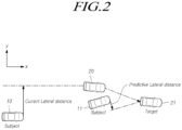
- a lateral position of the another vehicle at a current time point and a lateral position of the another vehicle at a TTC are illustrated.
- a consideration is given to a case in which the another vehicle 20 is detected at the position of the subject vehicle 10.
- a distance to a center of the subject vehicle 10 from a straight line extending in parallel with a traveling direction of the subject vehicle 10 from a center of the another vehicle 20 may be calculated as a lateral distance at the current time point (or a current lateral distance).
- a distance to a center of the subject vehicle 11 from a straight line extending in parallel with a traveling direction of the subject vehicle 11 from a center of the another vehicle 21 may be calculated as a lateral distance at the TTC (or a predictive lateral distance).
- y p_lat which is the predictive lateral distance may be calculated by Equation (1) below.
- y p _ lat ⁇ d long + V x , T ⁇ T ⁇ ⁇ x sin ⁇ ′ ⁇ T + d lat + V y , T ⁇ T ⁇ ⁇ y cos ⁇ ′ ⁇ T y p _ lat : Predictive Lateral distance d long : Relative longitudinal distance V x , T : Longitudinal Velocity , Target ⁇ T : Time variation ⁇ x : Longitudinal deviation , Subject ⁇ ′ : Yawrate , Subject d lat : Relative lateral distance V y , T : Lateral Velocity , Target ⁇ y : Lateral deviation , Subject
- Equation (1) d long represents a relative longitudinal distance to the another vehicle, V x,T represents a longitudinal velocity of the another vehicle, ⁇ T represents a time variation, ⁇ x represents a longitudinal deviation of the subject vehicle, ⁇ ' represents a yaw rate of the subject vehicle, d lat represents a relative lateral distance to the another vehicle, V y,T represents a lateral velocity of the another vehicle, and ⁇ y represents a lateral deviation of the subject vehicle.
- the calculator 130 may calculate a predictive overlap of the subject vehicle and a predictive overlap of the another vehicle on the basis of the calculated predictive lateral distance.
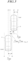
- an overlap, in which the subject vehicle 10 and the another vehicle 20 overlap each other may be calculated by Equation (2) below.
- Overlap ⁇ W Subject + W Target 2 ⁇ d Lat / W Subject W Subject + W Target 2 ⁇ d Lat 0 W Subject + W Target 2 ⁇ d Lat W Subject : Subject Width W Target : Target Width
- one-half of the width W subject of the subject vehicle 10 reaches a left line 41 or a right line 42.
- one-half of the width W target of the another vehicle 20 reaches a left line 51 or a right line 52.
- a distance to the center line 50 of the another vehicle 20 from the center line 40 of the subject vehicle 10 is represented by d lat
- a value obtained by avering one-half of the width W subject of the subject vehicle 10 and one-half of the width W target of the another vehicle 20 is less than d lat
- the another vehicle 20 is located more to the right than the right line 42 of the subject vehicle 10, and thus an overlap does not occur.
- the value by averaging one-half the width W subject of the subject vehicle 10 and one-half of the width W target of the another vehicle 20 is greater than d lat
- the another vehicle 20 is located more to the left than the right line 42 of the subject vehicle 10, and thus an overlap occurs.
- the calculator 130 may determine whether an overlap occurs, according to a current position and a predictive position of the subject vehicle 10 and a current position and a predictive position of the another vehicle 20.
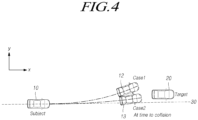
- FIGs. 4 and 5 illustrate examples of TTCs according to positions of the subject vehicle 10 and the another vehicle 20 and driving of the subject vehicle 10 and driving the another vehicle 20.
- FIG. 4 illustrates an example in which, while the another vehicle 20 continuously maintains straight driving, the subject vehicle 10 is steered to the left and approaches the another vehicle 20.
- the another vehicle is traveling straight ahead in a range corresponding to the width of the subject vehicle 10 with reference to a front straight line 30 of the subject vehicle 10, and thus a current overlap exists.
- the subject vehicle 10 is traveling while being steered largely to the left and travels (case 1)
- the another vehicle 20 gets farther away to the right with reference to the subject vehicle 12. That is, the another vehicle 20 is located in a direction which gets farther away from the left which is a steering direction of a subject vehicle 12. Therefore, it is predicted at the TTC that predictive overlap of the subject vehicle 12 and the another vehicle 20 will not occur.
- the calculator 130 may determine that when the subject vehicle 10 travels along the relevant driving path, steering avoidance is not needed. Therefore, the calculator 130 may determine that steering avoidance is inexecutable, and thus may not calculate steering avoidance information. That is, even when the current overlap is checked and a determination of whether avoidance braking is needed is started, a predictive overlap at a TTC is not checked, and thus unnecessary avoidance braking may not be performed.
- the calculator 130 may determine that steering avoidance is executable.
- the calculator 130 may determine that steering avoidance is needed. Therefore, the calculator 130 may determine that steering avoidance is executable, and thus may calculate steering avoidance information. That is, a current overlap is checked at the current time point and a predictive overlap is also checked at the TTC, and thus avoidance braking may be performed.
- steering avoidance information which causes the subject vehicle to be steered further to the left, may be calculated. Therefore, the control unit 140 control a steering device, a braking device, a velocity control device, or the like of the subject vehicle so that the subject vehicle travels according to the steering avoidance information.
- the calculator 130 may further determine whether a secondary collision may occur due to steering avoidance. For example, the calculator 130 may further determine, on the basis of information detected by the first detector 110, whether an obstacle, such as still another vehicle, exists in an adjacent lane in a direction in which the subject vehicle is to travel according to steering avoidance, or whether an adjacent lane does not exist, for example, in the case of the edge of a road, in the direction in which the subject vehicle is to travel according to steering avoidance. As described above, when whether a secondary collision may occur due to steering avoidance is checked, the calculator 130 may determine that steering avoidance is inexecutable, and may transmit, to the control unit 140, a signal notifying of a determination result.
- FIG. 5 illustrates a case in which, while the another vehicle 20 is steered to the right and travels, the subject vehicle 10 travels straight ahead and approaches the another vehicle 20.
- the another vehicle 20 is located in a left region with reference to a front straight line 30 of the subject vehicle 10.
- the another vehicle 20 is traveling while being steered to the right, in a range corresponding to the width of the subject vehicle 10 with reference to the front straight line 30 of the subject vehicle 10, and thus a current overlap exists at the current time point.
- another vehicle 21 is still located to the left with reference to a subject vehicle 14.
- the another vehicle 20 is located to the left with reference to the subject vehicles 10 and 14. Also, at the TTC, an overlap of the subject vehicle 14 and the another vehicle 21 is predicted to occur.
- the calculator 130 may determine that when the subject vehicle 10 travels along the relevant path, steering avoidance is needed. Therefore, the calculator 130 may determine that steering avoidance is executable, and thus may calculate steering avoidance information. That is, a current overlap is checked at the current time point and a predictive overlap is also checked at the TTC, and thus avoidance braking may be performed.
- the another vehicle is located to the left with reference to the subject vehicle from the current time point to the TTC, and thus steering avoidance information which causes the subject vehicle to be steered to the right may be calculated. Therefore, the control unit 140 may control a steering device, a braking device, a velocity control device, or the like of the subject vehicle so that the subject vehicle travels according to the steering avoidance information.
- the calculator 130 may further determine whether a secondary collision may occur due to steering avoidance, and may determine whether steering avoidance is performed.
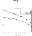
- FIGs. 6 and 7 illustrate examples of a current lateral distance and a predictive lateral distance, and a current overlap and a predictive overlap according to movements of the subject vehicle and the another vehicle in case 1 of FIG. 5 .
- the calculator 130 may determine that steering avoidance is executable.
- the another vehicle 20 when the another vehicle 20 is traveling while being steered largely to the right (case 2), at a TTC, the another vehicle 20 is located to the right with reference to the subject vehicle 14. That is, the another vehicle 20, which is located to the left with reference to the subject vehicle 10 at the current time point, is located to the right with reference to the subject vehicle 14 at the TTC.
- the calculator 130 may determine that steering avoidance is inexecutable.
- the subject vehicle is steered to the right, the amount of movement in a right lateral direction of the another vehicle is large, and thus there is a possibility of collision.
- a driving path of the subject vehicle may intersect with that of the another vehicle, and thus there is a possibility of collision.
- the calculator 130 may determine that steering avoidance is inexecutable, and may not calculate steering avoidance information. That is, even when a current overlap and a predictive overlap are checked, if a current lateral position and a predictive lateral position of the another vehicle are not located in the same region with reference to a center of the subject vehicle, in order to prevent the risk of collision, steering avoidance may not be performed. Therefore, safer steering avoidance may be performed.
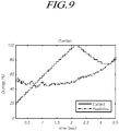
- FIGs. 8 and 9 illustrate examples of a current lateral distance and a predictive lateral distance, and a current overlap and a predictive ovelap according to movements of the subject vehicle and the another vehicle in case 2 of FIG. 5 . As illustrated in FIGs.
- a current overlap and a predictive overlap appear to continuously occur, but a current lateral distance appears to have a positive number and a predictive lateral distance appears to have a negative number, and thus the calculator 130 may determine that steering avoidance is inexecutable.
- the calculator 130 may calculate a target lateral movement distance constituting steering avoidance information. According to an embodiment, the calculator 130 may calculate a target lateral movement distance on the basis of a larger overlap value among current overlap information and predictive overlap information. This configuration is prepared for a case in which a lateral distance to the another vehicle just before a collision according to actual driving and a predictive lateral distance are different, and thus safer steering avoidance may be performed.
- the calculator 130 may calculate, as steering avoidance information, a steering avoidance time required to perform steering avoidance by using the calculated target lateral movement distance. For example, according to the performance of a subject vehicle, an allowable lateral acceleration of the subject vehicle may be different, and a response time for reaching the allowable lateral acceleration may also be different. Therefore, it is necessary to calculate a steering aviodance time required for the same steering avoidance.
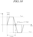
- FIG. 10 illustrates a graph of a lateral acceleration during steering avoidance of a subject vehicle.
- a horizontal axis represents time and a vertical axis represents a lateral acceleration.
- a response time required to reach an allowable lateral acceleration a y,cmd is t response .
- a yaw rate ⁇ ' of the subject vehicle is 0 deg/s, and steering avoidance is terminated.
- a time to t3, which is a termination time point of steering avoidance, from the time point t1 is steering avoidance time t Avcidance .
- the calculator 130 may calculate a required longitudinal distance on the basis of subject vehicle information and a steering avoidance time.
- a required longitudinal distance signifies a distance by which the subject vehicle longitudinally travels for a steering avoidance time in which the subject vehicle laterally travels according to steering avoidance information.
- a required longitudinal distance may calculated by Equation (3) below.
- d Avoidance t Avoidance ⁇ v rel + 1 2 a rel ⁇ t Avoidance 2
- d Avoidance Steering Avoidance Distance
- t Avoidance Steering Avoidance Time
- v rel Relative Longitudinal Velocity
- a rel Relative Longitudinal Acceleration
- Equation (3) d Avoidance represents a required longitudinal distance which is a steering avoidance distance, t Avoidance represents a steering avoidance time, v rel represents a relative longitudinal velocity, and a rel represents a relative longitudinal acceleration.
- the calculator 130 may determine that steering avoidance is executable. That is, when a required longitudinal distance is longer than a longitudinal distance to another vehicle, a subject vehicle travels by the longitudinal distance to the another vehicle before the elapse of a steering avoidance time, and thus a required lateral movement is not performed. Therefore, there is a possibility of collision.
- the control unit 140 may control a subject vehicle to perform steering avoidance at an allowable lateral acceleration in an avoidance direction. That is, as illustrated in FIG. 10 , the control unit 140 may control such that the subject vehicle has a lateral acceleration from the time point t1.
- control unit 140 may control such that the subject vehicle travels at an allowable lateral acceleration in a direction opposite to an avoidance direction from a time point which is faster by a response time than a steering avoidance time. That is, as illustrated in FIG. 10 , the control unit 140 may control such that the subject vehicle has a lateral acceleration in a direction opposite to the avoidance direction from a time point t2 which is faster by a response time t response than the time point t3. Accordingly, the subject vehicle decreasingly slowly moves in a lateral direction on and after the time point t2 and terminates the lateral movement at a desired lateral position, so that a yaw rate can approach 0. As a result, when the steering avoidance is completed, the attitude of the subject vehicle can be stably restored to the state before the steering avoidance.
- steering avoidance information for avoiding a collision with another vehicle is calculated so as to control the subject vehicle, thereby preventing execution of steering avoidance in a case where steering avoidance is not needed or is inexecutable.
- steering avoidance is performed by determining whether steering avoidance is executable, on the basis of whether a current overlap occurs and whether a predictive overlap occurs, which are detected on the basis of information of a subject vehicle and information of another vehicle, so that steering avoidance can be more safely performed.
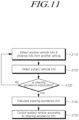
- FIG. 11 is a flowchart illustrating a collision avoidance method according to the present invention.
- the collision avoidance method according to the present invention may be implemented in the collision avoidance apparatus 100 described with reference to FIG. 1 .
- the collision avoidance method according to the present invention and an operation of the collision avoidance apparatus 100 for implementing the same will be described in detail with reference to the accompanying drawings.
- the collision avoidance apparatus may detect another vehicle information including a longitudinal velocity and a lateral velocity of another vehicle, and distance information including a longitudinal distance and a lateral distance from the another vehicle.
- a first detector of the collision avoidance apparatus may detect a distance from an object such as another vehicle by using at least one of sensors disposed in the subject vehicle, and may detect a relative velocity and a relative acceleration of the object on the basis of a distance from the detected object and an operating time of the detected object.
- a distance from the object may include a longitudinal distance and a lateral distance from the object.
- the first detector may include at least one of a camera sensor, a radar sensor, and an ultrasonic sensor.
- the camera sensor may include: a light collector configured to receive light; an imager configured to capture an image from the received light; an adjustment device configured to adjust a state; and the like.
- a radar sensor may emit an electromagnetic wave and may analyze an electromagnetic wave which is reflected and returns from an object, and may measure a distance from the object.
- An ultrasonic sensor may transmit a ultrasonic wave having a pulse waveform, and may detect a distance from an object on the basis of a time until the transmitted ultrasonic wave returns.
- this configuration is only an example, and thus the present invention is not limited thereto.
- the first detector is not limited to a particular sensor if the first detector can acquire another vehicle information or distance information.
- the collision avoidance apparatus may detect subject vehicle information including a velocity and a yaw rate of a subject vehicle.
- the second detector of the collision avoidance apparatus may detect a velocity of a subject vehicle by using a vehicle velocity sensor including a wheel velocity sensor which is one of vehicle sensors, and may detect an acceleration of the subject vehicle by using a gravity acceleration sensor.
- vehicle velocity sensor including a wheel velocity sensor which is one of vehicle sensors
- gravity acceleration sensor may detect an acceleration of the subject vehicle by using a gravity acceleration sensor.
- this configuration is only an example, and thus the second detector is not limited to a particular sensor if the second detector can detect a velocity or an acceleration of a subject vehicle.
- the second detector may detect another factor which is not a velocity or an acceleration, and may detect a velocity and an acceleration of a subject vehicle on the basis of the detected factor and the mechanism of a velocity or acceleration.
- the collision avoidance apparatus may determine whether steering avoidance is executable, on the basis of the another vehicle information, the subject vehicle information, and the distance information.
- a calculator of the collision avoidance apparatus may receive detected information from the first detector and the second detector.
- the calculator may determine whether steering avoidance is executable, on the basis of the another vehicle information, subject vehicle information, and distance information.
- the calculator may check whether a predetermined avoidance-executable condition is satisfied, on the basis of a current driving state and a predictive driving state of a subject vehicle and a current driving state and a predictive driving state of another vehicle. Also, when steering avoidance is not needed according to driving states of the subject vehicle and another vehicle, the calculator may determine that steering avoidance is inexecutable.
- the collision avoidance apparatus may return to operation S110 and may perform operation S110 and operations after operation S110.
- the collision avoidance apparatus may calculate steering avoidance information on steering avoidance of the subject vehicle
- the calculator of the collision avoidance apparatus may calculate steering avoidance information required to control steering avoidance of the subject vehicle.
- the calculator may calculate steering avoidance information, that is, a driving direction in which the subject vehicle should travel in order to avoid a collision with the another vehicle, a steering avoidance time for which the subject vehicle should travel in order to avoid a collision with another vehicle, a velocity or acceleration at which the subject vehicle should travel in order to avoid a collision with another vehicle, and the like.
- the collision avoidance apparatus may control the subject vehicle to travel according to the steering avoidance information.
- a control unit of the collision avoidance apparatus may receive the steering avoidance information calculated by the calculator.
- the control unit may control a steering device, a braking device, and the like disposed in the subject vehicle so that the subject vehicle travels according to the steering avoidance information.
- steering avoidance information for avoiding a collision with the another vehicle may be calculated, and the subject vehicle may be controlled according to the steering avoidance information, and thus, when steering avoidance is not needed or is inexecutable, execution of steering avoidance can be prevented.
- FIG. 12 is a flowchart illustrating a method for determining whether steering avoidance is executable according to the present invention.
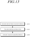
- FIG. 13 is a flowchart illustrating a method for calculating steering avoidance information according to the present invention.
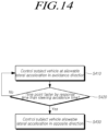
- FIG. 14 is a flowchart illustrating a method for controlling a subject vehicle according to the present invention.
- FIG. 12 specifically illustrates the determination of whether steering avoidance is executable, which is performed in operation S130 of FIG. 11 .
- the calculator of the collision avoidance apparatus may calculate a TTC on the basis of another vehicle information, subject vehicle information, and distance information.
- the calculator may receive, from the first detector of the collision avoidance apparatus, another vehicle information including a longitudinal velocity and a lateral velocity of another vehicle, and distance information including a longitudinal distance and a lateral distance from the another vehicle.
- the calculator may receive, from the second detector of the collision avoidance apparatus, subject vehicle information including a velocity and yaw rate of a subject vehicle.
- the calculator of the collision avoidance apparatus may calculate a TTC when a collision with the another vehicle is predicted, on the basis of the another vehicle information, the subject vehicle information, and the distance information.
- Various known methods can be applied to a method for calculating a TTC by using information of a subject vehicle and information of another vehicle, and the relevant method is not limited to a particular method.
- the collision avoidance apparatus may determine whether a current lateral position and a predictive lateral position of the another vehicle lie in the same direction with reference to a front straight line of the subject vehicle.
- the calculator may determine that steering avoidance is inexecutable, and may return to operation S110 of FIG. 11 , and may perform operation S110 and operations after operation S110.
- the calculator may determine whether there occurs a current overlap in which the subject vehicle and the another vehicle overlap each other at the current time point, on the basis of the another vehicle information, the subject vehicle information, and the distance information.
- the calculator may determine that steering avoidance is inexecutable, and may return to operation S110 of FIG. 11 , and may perform operation S110 and operations after operation S110.
- the calculator may determine whether there occurs a predictive overlap in which the subject vehicle and the another vehicle overlap each other at the TTC, on the basis of the another vehicle information, the subject vehicle information, and the distance information.
- the calculator may determine that steering avoidance is inexecutable, and may return to operation S110 of FIG. 11 , and may perform operation S110 and operations after operation S110.
- the calculator may determine that steering avoidance is executable. Then, as described in operation S140 of FIG. 11 , the calculator may calculate steering avoidance information.
- FIG. 13 specifically illustrates calculation of steering avoidance information, which is performed in operation S140 of FIG. 11 .
- the collision avoidance apparatus may calculate desired lateral movement distance on the basis of a larger overlap value among current overlap information and predictive overlap information.
- the calculator of the collision avoidance apparatus may calculate a desired lateral movement distance constituting steering avoidance information.
- the calculator may calculate a desired lateral movement distance on the basis of a larger overlap value among the current overlap information and the predictive overlap information. This configuration is prepared for a case in which a lateral distance to the another vehicle just before a collision according to actual driving is different from a lateral distance to the another vehicle at a TTC, and thus safer steering avoidance may be performed.
- the collision avoidance apparatus may calculate a steering avoidance time on the basis of a desired lateral movement distance, an allowable lateral acceleration of the subject vehicle, and a response time for reaching the allowable lateral acceleration.
- the calculator of the collision avoidance apparatus may calculate, as steering avoidance information, a steering avoidance time required to perform steering avoidance by using the calculated desired lateral movement distance. For example, according to the performance of a subject vehicle, an allowable lateral acceleration of the subject vehicle may be different, and a response time for reaching the allowable lateral acceleration may also be different. Therefore, it is necessary to calculate a steering aviodance time required for the same steering avoidance.
- the collision avoidance apparatus may calculate a required longitudinal distance on the basis of the subject vehicle information and a steering avoidance time.
- the calculator of the collision avoidance apparatus may calculate a required longitudinal distance on the basis of the subject vehicle information and the steering avoidance time.
- a required longitudinal distance signifies a distance by which the subject vehicle longitunally travels for a steering avoidance time for which the subject vehicle laterally travels according to the steering avoidance information.
- the calculator 130 may determine that steering avoidance is executable. That is, when a required longitudinal distance is longer than a longitudinal distance to the another vehicle, the subject vehicle travels by the longitudinal distance to the another vehicle before the elapse of a steering avoidance time, and thus a required lateral movement is not performed. Therefore, there is a possibility of collision.
- FIG. 14 specifically illustrates a method for controlling a subject vehicle according to steering avoidance information, which is performed in operation S150 of FIG. 11 .
- the control unit of the collision avoidance apparatus may control a subject vehcle to be steered at an allowable lateral acceleration in an avoidance direction.
- the control unit of the collision avoidance apparatus may determine whether a time point, which is faster by a response time than a steering avoidance time, has arrived after steering avoidance is started. When the time point, which is faster by a response time than a steering avoidance time, has not arrived (No in operation S420), the control unit of the collision avoidance apparatus may continuously perform operation S410.
- the control unit of the collision avoidance apparatus may control such that a subject vehicle travels at an allowable lateral acceleration in a direction opposite to an avoidance direction. That is, the control unit may control such that the subject vehicle has a lateral acceleration in a direction opposite to an avoidance direction from a time point which is faster by a response time than a steering avoidance time.
- the subject vehicle decreasingly slowly moves in a lateral direction on and after the time point, which is faster by a response time than a steering avoidance time, and terminates the lateral movement at a desired lateral position, so that a yaw rate can approach 0.
- the attitude of the subject vehicle can be stably restored to the state before the steering avoidance.
- steering avoidance information for avoiding a collision with another vehicle is calculated so as to control the subject vehicle, thereby preventing execution of steering avoidance in a case where steering avoidance is not needed or is inexecutable.
- steering avoidance is performed by determining whether steering avoidance is executable, on the basis of whether a current overlap occurs and whether a predictive overlap occurs, which are calculated on the basis of information of a subject vehicle and information of another vehicle, so that steering avoidance can be more safely performed.
- the present invention as described above may be implemented as computer-readable codes in a medium on which a program is recorded.
- the computer-readable mediums include all types of recording devices which may be read by a computer system and on which data are stored. Examples of the computer-readable medium include a Hard Disk Drive (HDD), a Solid State Disk (SSD), Silicon Disk Drive (SDD), a Read Only Memory (ROM), a Random Access Memory (RAM), CD-ROM, a magnetic tape, a floppy disk, and an optical data storage device, and may also include things implemented in the form of carrier wave (e.g. transmission through the Internet).
Applications Claiming Priority (1)
| Application Number | Priority Date | Filing Date | Title |
|---|---|---|---|
| KR1020180120072A KR101964858B1 (ko) | 2018-10-08 | 2018-10-08 | 충돌 방지 장치 및 충돌 방지 방법 |
Publications (3)
| Publication Number | Publication Date |
|---|---|
| EP3674155A2 EP3674155A2 (en) | 2020-07-01 |
| EP3674155A3 EP3674155A3 (en) | 2020-08-05 |
| EP3674155B1 true EP3674155B1 (en) | 2023-03-29 |
Family
ID=67624467
Family Applications (1)
| Application Number | Title | Priority Date | Filing Date |
|---|---|---|---|
| EP19202009.7A Active EP3674155B1 (en) | 2018-10-08 | 2019-10-08 | Collision avoidance apparatus and collision avoidance method |
Country Status (4)
| Country | Link |
|---|---|
| US (1) | US11203335B2 (ko) |
| EP (1) | EP3674155B1 (ko) |
| KR (1) | KR101964858B1 (ko) |
| CN (1) | CN111002979B (ko) |
Families Citing this family (9)
| Publication number | Priority date | Publication date | Assignee | Title |
|---|---|---|---|---|
| CN111464942A (zh) * | 2020-04-24 | 2020-07-28 | 捷开通讯(深圳)有限公司 | 一种车辆行驶的控制方法、装置、存储介质及终端 |
| CN112201055A (zh) * | 2020-11-10 | 2021-01-08 | 上海悦充网络科技有限公司 | 一种车辆行驶危险感应识别处理方法及系统 |
| CN117818623A (zh) * | 2020-11-19 | 2024-04-05 | 御眼视觉技术有限公司 | 交通工具的安全和关键信息记录机制 |
| CN113060134B (zh) * | 2021-04-22 | 2023-01-20 | 亿咖通(湖北)技术有限公司 | 一种车辆避障方法、电子设备及存储介质 |
| US20220348257A1 (en) * | 2021-04-28 | 2022-11-03 | Aptiv Technologies Limited | System and method of providing evasive steering assist |
| KR20220164127A (ko) * | 2021-06-03 | 2022-12-13 | 현대자동차주식회사 | 충돌 회피 측면 이동 시스템 |
| US20230068703A1 (en) * | 2021-08-24 | 2023-03-02 | Waymo Llc | Planning system for autonomously navigating around lane-sharing road agents |
| CN113911117A (zh) * | 2021-11-03 | 2022-01-11 | 北京胜能能源科技有限公司 | 一种车辆让路方法、装置、电子设备及存储介质 |
| CN114114321A (zh) * | 2022-01-20 | 2022-03-01 | 雷神等离子科技(杭州)有限公司 | 一种激光雷达检测目标的防撞预测方法和系统 |
Family Cites Families (16)
| Publication number | Priority date | Publication date | Assignee | Title |
|---|---|---|---|---|
| JP4131403B2 (ja) * | 2003-09-05 | 2008-08-13 | 株式会社デンソー | 衝突判定装置 |
| US9318023B2 (en) * | 2011-08-31 | 2016-04-19 | GM Global Technology Operations LLC | System and method for collision avoidance maneuver path determination with jerk limit |
| KR101361360B1 (ko) * | 2011-12-26 | 2014-02-11 | 현대자동차주식회사 | 측후방 감지센서를 이용한 차간거리 제어 시스템 및 그 제어 방법 |
| KR101428260B1 (ko) * | 2012-12-10 | 2014-08-07 | 현대자동차주식회사 | 외장에어백 전개방법 |
| KR101480610B1 (ko) * | 2013-05-21 | 2015-01-08 | 현대자동차주식회사 | 차량의 충돌 방지 장치 및 그 방법 |
| KR101510006B1 (ko) * | 2013-12-11 | 2015-04-07 | 현대자동차주식회사 | 외장에어백 전개방법 |
| JP5969534B2 (ja) * | 2014-04-21 | 2016-08-17 | 株式会社デンソー | 走行支援装置 |
| JP6302825B2 (ja) * | 2014-11-28 | 2018-03-28 | 株式会社アドヴィックス | 衝突回避装置 |
| JP6363558B2 (ja) | 2015-06-02 | 2018-07-25 | 株式会社デンソー | 車両制御装置、及び車両制御方法 |
| KR102509433B1 (ko) * | 2016-01-19 | 2023-03-13 | 주식회사 에이치엘클레무브 | 충돌방지장치 및 충돌방지방법 |
| CN106157696B (zh) * | 2016-08-30 | 2019-03-29 | 浙江吉利控股集团有限公司 | 基于车-车通信的自车主动避让系统和避让方法 |
| KR20180065585A (ko) * | 2016-12-08 | 2018-06-18 | 현대자동차주식회사 | 차량 및 그 제어방법 |
| KR102313025B1 (ko) * | 2017-04-03 | 2021-10-15 | 현대자동차주식회사 | 차량 및 그 제어방법 |
| JP6848794B2 (ja) * | 2017-09-29 | 2021-03-24 | トヨタ自動車株式会社 | 衝突回避支援装置 |
| US10239452B1 (en) * | 2017-11-15 | 2019-03-26 | Ford Global Technologies, Llc | Minimizing false collision avoidance warnings |
| JP6954243B2 (ja) * | 2018-07-25 | 2021-10-27 | トヨタ自動車株式会社 | 運転支援装置 |
-
2018
- 2018-10-08 KR KR1020180120072A patent/KR101964858B1/ko active
-
2019
- 2019-10-08 CN CN201910997328.8A patent/CN111002979B/zh active Active
- 2019-10-08 EP EP19202009.7A patent/EP3674155B1/en active Active
- 2019-10-08 US US16/595,747 patent/US11203335B2/en active Active
Also Published As
| Publication number | Publication date |
|---|---|
| US20200108825A1 (en) | 2020-04-09 |
| US11203335B2 (en) | 2021-12-21 |
| KR101964858B1 (ko) | 2019-08-13 |
| CN111002979B (zh) | 2024-03-29 |
| EP3674155A2 (en) | 2020-07-01 |
| EP3674155A3 (en) | 2020-08-05 |
| CN111002979A (zh) | 2020-04-14 |
Similar Documents
| Publication | Publication Date | Title |
|---|---|---|
| EP3674155B1 (en) | Collision avoidance apparatus and collision avoidance method | |
| US11059479B2 (en) | Collision avoidance apparatus and collision avoidance method | |
| US11884261B2 (en) | Vehicular trailer sway management system | |
| US11027653B2 (en) | Apparatus, system and method for preventing collision | |
| US10775799B2 (en) | Autonomous cruise control apparatus and method | |
| US10836388B2 (en) | Vehicle control method and apparatus | |
| EP2302412B1 (en) | System and method for evaluation of an automotive vehicle forward collision threat | |
| KR20200047886A (ko) | 운전자 보조 시스템 및 그 제어방법 | |
| KR102569904B1 (ko) | 표적 차량 추적 장치 및 그의 표적 차량 추적 방법과 그를 포함하는 차량 | |
| US11312371B2 (en) | Apparatus and method for controlling vehicle | |
| US10688974B2 (en) | Autonomous emergency braking system and method of controlling same | |
| US20190344784A1 (en) | Vehicle collision mitigation apparatus and method | |
| JP2018072105A (ja) | 物体検知装置 | |
| KR102505471B1 (ko) | 레이더 장착 각도 검출 장치 및 그 방법 | |
| US20190061748A1 (en) | Collision prediction apparatus | |
| EP4063912A1 (en) | Tracking different sections of articulated vehicles | |
| JP6668472B2 (ja) | 物体分類を有する動力車両の周辺領域をキャプチャーする方法、制御装置、運転者支援システム、及び動力車両 | |
| CN111086507A (zh) | 用于避免下一车道车辆的盲点的装置及方法 | |
| US20190128047A1 (en) | Apparatus and method for controlling vehicle | |
| US10759342B2 (en) | Apparatus and method for controlling collision alert | |
| US20220308233A1 (en) | Driver assistance system and operation method thereof | |
| KR20230171112A (ko) | 차량 및 그 제어 방법 | |
| KR20220092303A (ko) | 차량 및 그 제어 방법 |
Legal Events
| Date | Code | Title | Description |
|---|---|---|---|
| PUAI | Public reference made under article 153(3) epc to a published international application that has entered the european phase |
Free format text: ORIGINAL CODE: 0009012 |
|
| STAA | Information on the status of an ep patent application or granted ep patent |
Free format text: STATUS: THE APPLICATION HAS BEEN PUBLISHED |
|
| AK | Designated contracting states |
Kind code of ref document: A2 Designated state(s): AL AT BE BG CH CY CZ DE DK EE ES FI FR GB GR HR HU IE IS IT LI LT LU LV MC MK MT NL NO PL PT RO RS SE SI SK SM TR |
|
| AX | Request for extension of the european patent |
Extension state: BA ME |
|
| PUAL | Search report despatched |
Free format text: ORIGINAL CODE: 0009013 |
|
| AK | Designated contracting states |
Kind code of ref document: A3 Designated state(s): AL AT BE BG CH CY CZ DE DK EE ES FI FR GB GR HR HU IE IS IT LI LT LU LV MC MK MT NL NO PL PT RO RS SE SI SK SM TR |
|
| AX | Request for extension of the european patent |
Extension state: BA ME |
|
| RIC1 | Information provided on ipc code assigned before grant |
Ipc: B60W 30/09 20120101ALI20200629BHEP Ipc: B60W 30/095 20120101AFI20200629BHEP Ipc: B60W 10/20 20060101ALI20200629BHEP |
|
| STAA | Information on the status of an ep patent application or granted ep patent |
Free format text: STATUS: REQUEST FOR EXAMINATION WAS MADE |
|
| 17P | Request for examination filed |
Effective date: 20210204 |
|
| RBV | Designated contracting states (corrected) |
Designated state(s): AL AT BE BG CH CY CZ DE DK EE ES FI FR GB GR HR HU IE IS IT LI LT LU LV MC MK MT NL NO PL PT RO RS SE SI SK SM TR |
|
| RAP1 | Party data changed (applicant data changed or rights of an application transferred) |
Owner name: MANDO MOBILITY SOLUTIONS CORPORATION |
|
| RAP1 | Party data changed (applicant data changed or rights of an application transferred) |
Owner name: HL KLEMOVE CORP. |
|
| GRAP | Despatch of communication of intention to grant a patent |
Free format text: ORIGINAL CODE: EPIDOSNIGR1 |
|
| STAA | Information on the status of an ep patent application or granted ep patent |
Free format text: STATUS: GRANT OF PATENT IS INTENDED |
|
| INTG | Intention to grant announced |
Effective date: 20221209 |
|
| RIN1 | Information on inventor provided before grant (corrected) |
Inventor name: KIM, MINGYU |
|
| GRAS | Grant fee paid |
Free format text: ORIGINAL CODE: EPIDOSNIGR3 |
|
| GRAA | (expected) grant |
Free format text: ORIGINAL CODE: 0009210 |
|
| STAA | Information on the status of an ep patent application or granted ep patent |
Free format text: STATUS: THE PATENT HAS BEEN GRANTED |
|
| AK | Designated contracting states |
Kind code of ref document: B1 Designated state(s): AL AT BE BG CH CY CZ DE DK EE ES FI FR GB GR HR HU IE IS IT LI LT LU LV MC MK MT NL NO PL PT RO RS SE SI SK SM TR |
|
| REG | Reference to a national code |
Ref country code: CH Ref legal event code: EP |
|
| REG | Reference to a national code |
Ref country code: DE Ref legal event code: R096 Ref document number: 602019026834 Country of ref document: DE |
|
| REG | Reference to a national code |
Ref country code: AT Ref legal event code: REF Ref document number: 1556483 Country of ref document: AT Kind code of ref document: T Effective date: 20230415 |
|
| REG | Reference to a national code |
Ref country code: IE Ref legal event code: FG4D |
|
| REG | Reference to a national code |
Ref country code: LT Ref legal event code: MG9D |
|
| PG25 | Lapsed in a contracting state [announced via postgrant information from national office to epo] |
Ref country code: RS Free format text: LAPSE BECAUSE OF FAILURE TO SUBMIT A TRANSLATION OF THE DESCRIPTION OR TO PAY THE FEE WITHIN THE PRESCRIBED TIME-LIMIT Effective date: 20230329 Ref country code: NO Free format text: LAPSE BECAUSE OF FAILURE TO SUBMIT A TRANSLATION OF THE DESCRIPTION OR TO PAY THE FEE WITHIN THE PRESCRIBED TIME-LIMIT Effective date: 20230629 Ref country code: LV Free format text: LAPSE BECAUSE OF FAILURE TO SUBMIT A TRANSLATION OF THE DESCRIPTION OR TO PAY THE FEE WITHIN THE PRESCRIBED TIME-LIMIT Effective date: 20230329 Ref country code: LT Free format text: LAPSE BECAUSE OF FAILURE TO SUBMIT A TRANSLATION OF THE DESCRIPTION OR TO PAY THE FEE WITHIN THE PRESCRIBED TIME-LIMIT Effective date: 20230329 Ref country code: HR Free format text: LAPSE BECAUSE OF FAILURE TO SUBMIT A TRANSLATION OF THE DESCRIPTION OR TO PAY THE FEE WITHIN THE PRESCRIBED TIME-LIMIT Effective date: 20230329 |
|
| REG | Reference to a national code |
Ref country code: NL Ref legal event code: MP Effective date: 20230329 |
|
| REG | Reference to a national code |
Ref country code: AT Ref legal event code: MK05 Ref document number: 1556483 Country of ref document: AT Kind code of ref document: T Effective date: 20230329 |
|
| PG25 | Lapsed in a contracting state [announced via postgrant information from national office to epo] |
Ref country code: SE Free format text: LAPSE BECAUSE OF FAILURE TO SUBMIT A TRANSLATION OF THE DESCRIPTION OR TO PAY THE FEE WITHIN THE PRESCRIBED TIME-LIMIT Effective date: 20230329 Ref country code: NL Free format text: LAPSE BECAUSE OF FAILURE TO SUBMIT A TRANSLATION OF THE DESCRIPTION OR TO PAY THE FEE WITHIN THE PRESCRIBED TIME-LIMIT Effective date: 20230329 Ref country code: GR Free format text: LAPSE BECAUSE OF FAILURE TO SUBMIT A TRANSLATION OF THE DESCRIPTION OR TO PAY THE FEE WITHIN THE PRESCRIBED TIME-LIMIT Effective date: 20230630 Ref country code: FI Free format text: LAPSE BECAUSE OF FAILURE TO SUBMIT A TRANSLATION OF THE DESCRIPTION OR TO PAY THE FEE WITHIN THE PRESCRIBED TIME-LIMIT Effective date: 20230329 |
|
| PG25 | Lapsed in a contracting state [announced via postgrant information from national office to epo] |
Ref country code: SM Free format text: LAPSE BECAUSE OF FAILURE TO SUBMIT A TRANSLATION OF THE DESCRIPTION OR TO PAY THE FEE WITHIN THE PRESCRIBED TIME-LIMIT Effective date: 20230329 Ref country code: RO Free format text: LAPSE BECAUSE OF FAILURE TO SUBMIT A TRANSLATION OF THE DESCRIPTION OR TO PAY THE FEE WITHIN THE PRESCRIBED TIME-LIMIT Effective date: 20230329 Ref country code: PT Free format text: LAPSE BECAUSE OF FAILURE TO SUBMIT A TRANSLATION OF THE DESCRIPTION OR TO PAY THE FEE WITHIN THE PRESCRIBED TIME-LIMIT Effective date: 20230731 Ref country code: ES Free format text: LAPSE BECAUSE OF FAILURE TO SUBMIT A TRANSLATION OF THE DESCRIPTION OR TO PAY THE FEE WITHIN THE PRESCRIBED TIME-LIMIT Effective date: 20230329 Ref country code: EE Free format text: LAPSE BECAUSE OF FAILURE TO SUBMIT A TRANSLATION OF THE DESCRIPTION OR TO PAY THE FEE WITHIN THE PRESCRIBED TIME-LIMIT Effective date: 20230329 Ref country code: AT Free format text: LAPSE BECAUSE OF FAILURE TO SUBMIT A TRANSLATION OF THE DESCRIPTION OR TO PAY THE FEE WITHIN THE PRESCRIBED TIME-LIMIT Effective date: 20230329 |
|
| PGFP | Annual fee paid to national office [announced via postgrant information from national office to epo] |
Ref country code: GB Payment date: 20230821 Year of fee payment: 5 |
|
| PG25 | Lapsed in a contracting state [announced via postgrant information from national office to epo] |
Ref country code: SK Free format text: LAPSE BECAUSE OF FAILURE TO SUBMIT A TRANSLATION OF THE DESCRIPTION OR TO PAY THE FEE WITHIN THE PRESCRIBED TIME-LIMIT Effective date: 20230329 Ref country code: PL Free format text: LAPSE BECAUSE OF FAILURE TO SUBMIT A TRANSLATION OF THE DESCRIPTION OR TO PAY THE FEE WITHIN THE PRESCRIBED TIME-LIMIT Effective date: 20230329 Ref country code: IS Free format text: LAPSE BECAUSE OF FAILURE TO SUBMIT A TRANSLATION OF THE DESCRIPTION OR TO PAY THE FEE WITHIN THE PRESCRIBED TIME-LIMIT Effective date: 20230729 |
|
| PGFP | Annual fee paid to national office [announced via postgrant information from national office to epo] |
Ref country code: FR Payment date: 20230821 Year of fee payment: 5 |
|
| REG | Reference to a national code |
Ref country code: DE Ref legal event code: R097 Ref document number: 602019026834 Country of ref document: DE |
|
| PG25 | Lapsed in a contracting state [announced via postgrant information from national office to epo] |
Ref country code: DK Free format text: LAPSE BECAUSE OF FAILURE TO SUBMIT A TRANSLATION OF THE DESCRIPTION OR TO PAY THE FEE WITHIN THE PRESCRIBED TIME-LIMIT Effective date: 20230329 Ref country code: CZ Free format text: LAPSE BECAUSE OF FAILURE TO SUBMIT A TRANSLATION OF THE DESCRIPTION OR TO PAY THE FEE WITHIN THE PRESCRIBED TIME-LIMIT Effective date: 20230329 |
|
| PGFP | Annual fee paid to national office [announced via postgrant information from national office to epo] |
Ref country code: DE Payment date: 20230822 Year of fee payment: 5 |
|
| PLBE | No opposition filed within time limit |
Free format text: ORIGINAL CODE: 0009261 |
|
| STAA | Information on the status of an ep patent application or granted ep patent |
Free format text: STATUS: NO OPPOSITION FILED WITHIN TIME LIMIT |
|
| 26N | No opposition filed |
Effective date: 20240103 |