EP3674152B1 - Hochleistungskraftfahrzeug mit gasdüsen - Google Patents
Hochleistungskraftfahrzeug mit gasdüsen Download PDFInfo
- Publication number
- EP3674152B1 EP3674152B1 EP19219312.6A EP19219312A EP3674152B1 EP 3674152 B1 EP3674152 B1 EP 3674152B1 EP 19219312 A EP19219312 A EP 19219312A EP 3674152 B1 EP3674152 B1 EP 3674152B1
- Authority
- EP
- European Patent Office
- Prior art keywords
- car
- compressed air
- gas
- air tank
- nozzles
- Prior art date
- Legal status (The legal status is an assumption and is not a legal conclusion. Google has not performed a legal analysis and makes no representation as to the accuracy of the status listed.)
- Active
Links
Images


Classifications
-
- B—PERFORMING OPERATIONS; TRANSPORTING
- B62—LAND VEHICLES FOR TRAVELLING OTHERWISE THAN ON RAILS
- B62D—MOTOR VEHICLES; TRAILERS
- B62D37/00—Stabilising vehicle bodies without controlling suspension arrangements
-
- B—PERFORMING OPERATIONS; TRANSPORTING
- B60—VEHICLES IN GENERAL
- B60T—VEHICLE BRAKE CONTROL SYSTEMS OR PARTS THEREOF; BRAKE CONTROL SYSTEMS OR PARTS THEREOF, IN GENERAL; ARRANGEMENT OF BRAKING ELEMENTS ON VEHICLES IN GENERAL; PORTABLE DEVICES FOR PREVENTING UNWANTED MOVEMENT OF VEHICLES; VEHICLE MODIFICATIONS TO FACILITATE COOLING OF BRAKES
- B60T1/00—Arrangements of braking elements, i.e. of those parts where braking effect occurs specially for vehicles
- B60T1/12—Arrangements of braking elements, i.e. of those parts where braking effect occurs specially for vehicles acting otherwise than by retarding wheels, e.g. jet action
-
- B—PERFORMING OPERATIONS; TRANSPORTING
- B60—VEHICLES IN GENERAL
- B60B—VEHICLE WHEELS; CASTORS; AXLES FOR WHEELS OR CASTORS; INCREASING WHEEL ADHESION
- B60B39/00—Increasing wheel adhesion
-
- B—PERFORMING OPERATIONS; TRANSPORTING
- B60—VEHICLES IN GENERAL
- B60T—VEHICLE BRAKE CONTROL SYSTEMS OR PARTS THEREOF; BRAKE CONTROL SYSTEMS OR PARTS THEREOF, IN GENERAL; ARRANGEMENT OF BRAKING ELEMENTS ON VEHICLES IN GENERAL; PORTABLE DEVICES FOR PREVENTING UNWANTED MOVEMENT OF VEHICLES; VEHICLE MODIFICATIONS TO FACILITATE COOLING OF BRAKES
- B60T1/00—Arrangements of braking elements, i.e. of those parts where braking effect occurs specially for vehicles
- B60T1/12—Arrangements of braking elements, i.e. of those parts where braking effect occurs specially for vehicles acting otherwise than by retarding wheels, e.g. jet action
- B60T1/14—Arrangements of braking elements, i.e. of those parts where braking effect occurs specially for vehicles acting otherwise than by retarding wheels, e.g. jet action directly on road
-
- B—PERFORMING OPERATIONS; TRANSPORTING
- B62—LAND VEHICLES FOR TRAVELLING OTHERWISE THAN ON RAILS
- B62D—MOTOR VEHICLES; TRAILERS
- B62D37/00—Stabilising vehicle bodies without controlling suspension arrangements
- B62D37/02—Stabilising vehicle bodies without controlling suspension arrangements by aerodynamic means
-
- F—MECHANICAL ENGINEERING; LIGHTING; HEATING; WEAPONS; BLASTING
- F04—POSITIVE - DISPLACEMENT MACHINES FOR LIQUIDS; PUMPS FOR LIQUIDS OR ELASTIC FLUIDS
- F04D—NON-POSITIVE-DISPLACEMENT PUMPS
- F04D21/00—Pump involving supersonic speed of pumped fluids
Definitions
- the invention relates to a high-performance car with gas pushers.
- Patent application WO2007144914A1 describes a road vehicle (car or motorcycle), which is provided with a compressed air tank and with gas pushers connected to the compressed air tank; in case of emergency, the gas pushers are operated so as to generate, in the road vehicle, a (transversely oriented) additional thrust with a pneumatic origin, which stabilizes (as much as possible) the road vehicle.
- Patent applications WO2008074608A1 , DE102008037803A1 , DE102009059803A1 , DE102011113513A1 , DE102011113516 , WO200345749A1 , US20050230176A1 and WO2009083010A1 as well as patent US3719256A describe a car, which is provided with single-use gas pushers using a propellant (namely, pyrotechnic gas pushers); in case of emergency (for example, when the car is losing grip or risks rolling over or is about to hit a front obstacle), the gas pushers are operated so as to generate, in the car, a (transversely, longitudinally or vertically oriented) additional pneumatic thrust, which stabilizes or slows down (as much as possible) the car.
- a propellant namely, pyrotechnic gas pushers
- Patent application CN104309563A describes a car, which is provided with gas pushers consisting of pulsejets; in case of emergency (for example, when the car is losing grip or risks rolling over or is about to hit a front obstacle), the gas pushers are operated so as to generate, in the car, a (transversely, longitudinally or vertically oriented) additional pneumatic thrust, which stabilizes or slows down (as much as possible) the car.
- gas pushers consisting of pulsejets
- Patent applications WO2014090439A1 , WO2014206642A1 and WO2018001587A1 describe a motorcycle, which is provided with a compressed air tank and with gas pushers connected to the compressed air tank; in case of emergency (for example, when the motorcycle is losing rip and risks falling), the gas pushers are operated so as to generate, in the motorcycle, a (transversely oriented) additional thrust with a pneumatic origin, which stabilizes (as much as possible) the motorcycle.
- Patent US2724450A describes a car, which is provided with orientable gas pushers, which are connected to the exhaust duct of the internal combustion engine: in use, the exhaust gas is emitted by the gas pushers in order to generate, in the car, an additional pneumatic thrust.
- Patent application CN102514557A1 and patent US6191686B1 describe a car, which is provided with a compressed air tank and with gas pushers connected to the compressed air tank; in case of emergency (for example, when the car is losing grip or is about to hit a front obstacle), the gas pushers are operated so as to generate, in the car, a (transversely, longitudinally or vertically oriented) additional pneumatic thrust, which stabilizes or slows down (as much as possible) the car.
- the object of the invention is to provide a high-performance car with gas pushers, which is capable of increasing the performances of the car.
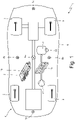
- number 1 indicates, as a whole, a car provided with two front wheels 2 and two rear drive wheels 3, which receive the torque from a powertrain system 4.
- the powertrain system 4 can be an exclusively heat-based system (namely, solely comprising an internal combustion heat engine), a hybrid system (namely, comprising an internal combustion heat engine and at least one electric motor) or an electric system (namely, solely comprising one or more electric motors).
- the car 1 comprises a frame 5, which supports the powertrain system 4 and the wheels 2 and 3 (namely, the four wheels 2 and 3 are fitted to the frame 5 in a rotary manner through the corresponding suspensions). Furthermore, the car 1 comprises a body 6 (better shown in figure 5 ), which covers the frame 5 and is mounted on the frame 5.
- the car 1 comprises at least one compressed air tank 7, which, for example, could have a nominal pressure of 700-900 bar.
- compressed air tank 7 which can be permanently connected to one another in a pneumatic manner (so as to have the same inner pressure) or can be pneumatically independent of one another.
- the car 1 comprises a plurality of gas pushers 8 (namely, pneumatic pushers 8), each of which is connected to the compressed air tank 7 in order to receive compressed air from the compressed air tank 7, is integral to the frame 5 (namely, transmits the pneumatic thrust to the frame 5) and has a plurality of nozzles 9 (shown in figures 2 and 3 ), which face outwards (from the body 6 and, hence, from the car 1) and can be activated so as to each generate an air jet flowing out of the nozzle 9.
- the pneumatic thrust generated by each gas pusher 8 directly acts upon the frame 5 (namely, upon the structure) of the car 1 without using the tyres of the wheels 2 and 3.
- each nozzle 9 comprises a tubular and cylindrical support body 10 containing an emitter 11, where an outlet opening 12 is obtained, through which compressed air flows out. Furthermore, each nozzle 9 comprises an electromagnetic adjustment valve 13, which can be controlled so as to open or close the nozzle 9, namely so as to generate or not to generate the air jet flowing out of the nozzle 9. Each nozzle is connected to the compressed air jet 7 (namely, receives air from the compressed air jet 7) through a duct 14. Each nozzle 9 is shaped so as to generate a supersonic air jet, namely an air jet in which the air has a greater speed than sound speed.
- each nozzle 9 is a valve, which opens and closes - upon command - a compressed air flow, which is accelerated during the expansion at supersonic speed.
- each gas pusher 8 comprises a plurality of nozzles 9, which are arranged parallel to and beside one another, have the same orientation (namely, generate respective air jets that are parallel to one another) and are sized so as to generate different pneumatic thrusts given the same pressure of the compressed air flowing in; in other words, when the pressure of the compressed air flowing into the nozzles 9 is the same, the pneumatic thrusts generated by the different nozzles 9 of a same gas pusher 8 are different from one another.
- This result is normally obtained by differentiating the size (in particular, the diameter) of the outlet openings 12 of the nozzles 9 (under the same conditions, the greater the diameter of the outlet opening 12, the greater the pneumatic thrust generated).
- a pressure sensor 15 which determines (measures) a pressure inside the compressed air tank 7. Furthermore, an electronic control unit 16 is provided, which, in each gas pusher 8, activates the plurality of nozzles 9 in a coordinated manner so as to generate, as a whole, a desired pneumatic thrust based on the pressure inside the compressed air tank 7.
- the electronic control unit 16 determines, based on the state of motion of the car 1, when to activate each gas pusher 8 and, especially, determines the pneumatic thrust (which is force and, hence, is measured in Newton) to be generated by each gas pusher 8; once the desired pneumatic thrust of a gas pusher 8 is known, the electronic control unit 16 activates the nozzles 9 of the gas pusher 8 in a coordinated manner so as to generate, as a whole, the desired pneumatic thrust based on the pressure inside the compressed air tank 7.
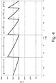
- the control unit 16 progressively activates the nozzles 9, which, given the same pressure, would generate a greater pneumatic thrust as the pressure inside the compressed air tank 7 decreases.
- the control unit 16 activates, at first, the nozzle 9 with the smallest outlet opening 12 of all, which in the window I (namely, between the instant 0 and the instant 1.2) generates a pneumatic thrust ranging from 5000 to 4000 Newton, then it activates the nozzle 9 with a slightly larger outlet opening 12, which in the window II (namely, between the instant 1.2 and the instant 2.7) generates a pneumatic thrust ranging from 6000 to 4000 Newton, then it activates the nozzle 9 with a slightly larger outlet opening 12, which in the window III (namely, between the instant 2,7 and the instant 3,7) generates a pneumatic thrust ranging from 6000 to 4000 Newton, then it activates the nozzle 9 with
- the pressure of the compressed air inside the compressed air tank 7 keeps decreasing due the continue outlet of compressed air from the compressed air tank 7; namely, with every opening (activation) of a nozzle 9 of a gas pusher 8, the pressure of the compressed air in the compressed air tank 7 constantly and quickly decreases and, hence, the pneumatic thrust generated by the nozzle 9 constantly and quickly decreases as well in the same way.
- control unit 16 activates the nozzle 9 generating the pneumatic thrust closest to the desired pneumatic thrust based on the pressure inside the compressed air tank 7 and this leads to the switching, in succession, of the nozzle 9, which is activated due to the progressive decrease in the pressure of the compressed air inside the compressed air tank 7.
- the pneumatic thrust generated by each nozzle 9 basically depends on the pressure of the compressed air and on the diameter of the outlet opening 11: using the same compressed air tank 7 and different nozzles 9 of a same pusher 8, different levels of pneumatic thrust can be generated and the pneumatic pressure can remain approximately constant over time.
- control unit 16 in a same gas pusher 8, the control unit 16 always activates one single nozzle 9 at a time; according to other embodiments, in a same gas pusher 8, the control unit 16 could also simultaneously activate different nozzles 9 so as to sum the pneumatic thrusts generated by the nozzles 9.
- the control unit 16 in emergency situations (for example, when there is probably going to be of a front impact that cannot be avoided using the sole braking power generated by the braking system acting upon the wheels 2 and 3), the control unit 16 is aimed at generating the maximum pneumatic thrust possible and, hence, could simultaneously open (activate), in the chosen gas pusher 8 (or in the chosen gas pushers 8), all the nozzles 9 present.
- a compressor 17 is provided, which is connected to the compressed air tank 7 and is designed to receive the motion from a front axle (namely, from the two front wheels 2) or from a rear axle (namely, from the two rear wheels 3).
- a rotor of the compressor 17 can be connected to the front axle (namely, to the two front wheels 2) or to the rear axle (namely, to the two rear wheels 3) in order to be operated by the front wheels 2 or by the rear wheels 3 (thus, exploiting the motion of the front wheels 2 or the motion of the rear wheels 3).
- the control unit 16 activates the compressor 17, using the motion received from the wheels 2 or 3, during the braking phase so as to use the kinetic energy owned by the car 1, which otherwise would be dissipated in heat by the braking system.
- a heat exchanger 18 is provided, which is interposed between the compressor 17 and the compressed air tank 7 and is designed to cool down the compressed air fed by the compressor 17 to the compressed air tank 7, thus reducing the volume occupied by the compressed air in the compressed air tank 7; thanks to the cooling of the compressed air fed by the compressor 17 to the compressed air tank 7, a greater quantity (mass) of compressed air can be stored in the compressed air tank 7, the pressure being equal.
- the car 1 comprises (at least) one gas pusher 8a, which is preferably arranged in the area of a centre of gravity of the car 1 and where the nozzles 9 are oriented vertically upwards; as a consequence, when it is activated, the pusher 8a generates a pneumatic thrust that pushes the car 1 towards the ground, namely increased the vertical load acting upon the car 1.
- the gas pusher 8a is used to increase the vertical load acting upon the car 1 and, hence, increase the total force that the tyres of the wheels 2 and 3 can release to the ground; therefore, the action of the gas pusher 8a increases the performances of the car 1 in any condition (while accelerating, braking and driving along a curve).
- the car 1 comprises two gas pushers 8b, which are preferably arranged in the area of a centre of gravity of the car 1 and where the nozzles 9 are oriented horizontally and transversely, respectively, on a right side and on a left side; as a consequence, when they are activated alternatively (namely, never together, but always one at a time), the pushers 8b generate a pneumatic thrust that transversely (laterally) pushes the car 1 to the ground.
- Each gas pusher 8b is used to counter the centrifugal force developed while driving along a curve and, hence, to increase the maximum speed at which the curved is covered.
- the car 1 comprises a gas pusher 8c, which is arranged in a front position and where the nozzles 9 are oriented horizontally and longitudinally; as a consequence, when it is activated, the pusher 8c generates a pneumatic thrust that brakes the car 1 (namely, slows down the car 1).
- the car 1 comprises a gas pusher 8d, which is arranged in a rear position and where the nozzles 9 are oriented horizontally and longitudinally; as a consequence, when it is activated, the pusher 8d generates a pneumatic thrust that accelerates the car 1.
- the car 1 comprises a gas pusher 8d, which is arranged in the area of a floor and where the nozzles 9 are oriented towards a road surface and towards the back of the car 1; as a consequence, when it is activated, the pusher 8e generates a pneumatic thrust between the floor of the car 1 and the road surface, which accelerates the air flow under the car 1 and, hence, due to a Venturi effect, decreases the pressure of the air under car 1, thus increasing the vertical load acting upon the car 1 and, hence, increasing the total force that can be released by the wheels 2 and 3 to the ground; therefore, the action of the gas pusher 8c increases the performances of the car 1 while accelerating and driving along a curve.
- the gas pusher 8d which is arranged in the area of a floor and where the nozzles 9 are oriented towards a road surface and towards the back of the car 1; as a consequence, when it is activated, the pusher 8e generates a pneumatic thrust between the floor of the car 1 and the road surface, which accelerate
- the gas pushers 8 could have a different arrangement: for example, the gas pusher 8a could be arranged closer to (even in the area of) the front axle or it could be arranged closer to (even in the area of) the rear axle.
- the car 1 could comprise a greater number of gas pushers 8: for example, two gas pushers 8a arranged in the area of the front axle and of the rear axle, four gas pushers 8b arranged in pairs in the area of the front axle and of the rear axle, two or more gas pushers 8c, two or more gas pushers 8d or two or more gas pushers 8a.
- the car 1 could comprise a smaller number of gas pushers 8: for example, there could be the sole gas pusher 8a, there could be the sole gas pushers 8b, there could be the sole gas pusher 8c, there could be the sole gas pusher 8d or there could be the sole gas pusher 8e.
- the use (the presence) of the gas pusher 8a is more convenient when the tyres of the wheels 2 and 3 are high-performance tyres and have a friction coefficient of more than 1, since the friction coefficient of more than 1 allows for a multiplication of (namely, an increase in) the final effect of the pneumatic thrust acting vertically: for example, a greater vertical load of 1000 Newton generated by the gas pusher 8a translates into a greater acceleration force acting upon the vehicle equal to 1500 Newton, if the friction coefficient between the tyres and the road surface is 1.5 (maximum value of a racing slick tyre), and, on the other hand, translates into a greater acceleration force acting upon the vehicle equal to 800 Newton, if the friction coefficient between the tyres and the road surface is 0.8 (typical value of a good road tyre for common use) .
- the gas pushers 8a-8d in order to have a significant effect, require a not too low pressure of the compressed air inside the compressed air tank 7; on the contrary, the gas pusher 8e has a significant effect even when the pressure of the compressed air inside the compressed air tank 7 is lower, for the main aim of the gas pusher 8e is not to generate a relevant pneumatic thrust, but is the generation of a depression under the floor of the car 1.
- the gas pushers 8 when the gas pushers 8 are activated, attention should be paid to not “jeopardizing” ( “damaging” ) the aerodynamics of the car 1 in order to avoid experiencing a loss of aerodynamic load when there is a gain thanks to the pneumatic thrust generated by the gas pushers 8; for example, the gas pushers 8 could be used only at low speeds (for example, when staring from a still position or when driving along a very sharp bend) or in case of emergency (typically, an emergency braking).
- the compressed air tank 7 is only filled when the car 1 is standing still by means of an external filling system; in this case, obviously, the gas pushers 8 are used rarely and in case of emergency (namely, in case of an immediate danger) or they are used in case of very short road stretches (for example, when the best time has to be obtained in a single lap of a track).
- the gas pushers 8 do not operate through compressed air (namely, they do not receive compressed air from the compressed air tank 7, which is not present), but are pulsejets, which are supplied with a liquid fuel (typically, the same liquid fuel supplying an internal combustion heat engine of the powertrain system 4, namely petrol or Diesel) to generate a high-speed gas flow, which flows out of the corresponding nozzle 9; in this embodiment, each gas pusher 8 comprises one single nozzle 9, as the adjustment of the pneumatic thrust is carried out by adjusting the supply of liquid fuel.
- a pulsejet is a very simple form of jet engine, in which the combustion takes place in an intermittent manner generating a pulsed thrust; the combustion produces a high-pressure gas, which expands up to supersonic speed in the nozzle 9.
- the car 1 described above has numerous advantages.
- the car 1 disclosed above allows for an effective and efficient achievement of performances that are significantly higher than the performances of a similar car 1 without the gas pushers 8.
- the car 1 disclosed above experiences a modest weight increase compared to a similar car 1 without the gas pushers 8, since the gas pushers 8 and the compressed air tank 7 can generate, as a whole, a weight increase of approximately 40-45 kg.
- the gas pushers 8 are very small and, hence, their integration in the car 1 is relatively simple, whereas the compressed air tank 7 is more large-sized, but it can easily be placed in the empty spaces available in the car 1, which otherwise would not be used.
Landscapes
- Engineering & Computer Science (AREA)
- Mechanical Engineering (AREA)
- Transportation (AREA)
- Chemical & Material Sciences (AREA)
- Combustion & Propulsion (AREA)
- Physics & Mathematics (AREA)
- Fluid Mechanics (AREA)
- General Engineering & Computer Science (AREA)
- Vehicle Body Suspensions (AREA)
- Feeding Of Workpieces (AREA)
Claims (14)
- Fahrzeug (1), mit:einem Rahmen (5);vier Rädern (2, 3), die auf eine drehbare Weise am Rahmen (5) montiert sind;einer Karosserie (6), die den Rahmen (5) abdeckt;mindestens einem Drucklufttank (7);einem Drucksensor (15), der einen Druck innerhalb des Drucklufttanks (7) bestimmt; undmindestens einer Gasausstoßeinrichtung (8), die mit dem Drucklufttank (7) verbunden ist, integral mit dem Rahmen (5) ausgebildet ist, mindestens eine nach außen gerichtete Düse (9) aufweist und aktiviert werden kann, um einen aus der Düse ausströmenden Luftstrahl zu erzeugen; undeiner Steuereinheit (16), die die Gasausstoßeinrichtung (8) bei Bedarf aktiviert;wobei das Fahrzeug dadurch gekennzeichnet ist, dass:die Gasausstoßeinrichtung (8) eine Vielzahl von Düsen (9) aufweist, die parallel zueinander und nebeneinander angeordnet sind, die gleiche Ausrichtung haben und so bemessen sind, dass sie bei gleichem Druck der einströmenden Druckluft unterschiedliche pneumatische Schübe erzeugen; unddie Steuereinheit (16) die Vielzahl von Düsen (9) auf eine koordinierte Weise aktiviert, um insgesamt einen gewünschten pneumatischen Schub basierend auf dem Druck im Drucklufttank (7) zu erzeugen.
- Fahrzeug (1) nach Anspruch 1, wobei die Steuereinheit (16) die Düsen (9) schrittweise aktiviert, die bei gleichem Druck einen größeren pneumatischen Schub erzeugen würden, wenn der Druck im Druckluftbehälter (7) abnimmt.
- Fahrzeug (1) nach Anspruch 1 oder 2, wobei die Steuereinheit (16) die Düse (9), die den pneumatischen Schub erzeugt, der dem gewünschten pneumatischen Schub am nächsten liegt, basierend auf dem Druck innerhalb des Drucklufttanks (7) aktiviert.
- Fahrzeug (1) nach Anspruch 1, 2 oder 3, wobei die Düsen (9) jeweils Auslassöffnungen (12) mit unterschiedlichen Durchmessern aufweisen.
- Fahrzeug (1) nach einem der Ansprüche 1 bis 4 und mit einem Kompressor (17), der mit dem Drucklufttank (7) verbunden und dafür konfiguriert ist, die Bewegung von mindestens einem Rad (2, 3) zu empfangen.
- Fahrzeug (1) nach Anspruch 5, wobei der Kompressor (17) dafür konfiguriert ist, die Bewegung von einer Vorderachse mit zwei Vorderrädern (2) zu empfangen.
- Fahrzeug (1) nach Anspruch 5 oder 6, wobei die Steuereinheit (16) den Kompressor (17) unter Verwendung der von mindestens einem Rad (2, 3) empfangenen Bewegung während der Bremsphase aktiviert.
- Fahrzeug (1) nach Anspruch 5, 6 oder 7, mit einem Wärmetauscher (18), der zwischen dem Kompressor (17) und dem Drucklufttank (7) angeordnet und dafür konfiguriert ist, die dem Drucklufttank (7) vom Kompressor (17) zugeführte Druckluft zu kühlen.
- Fahrzeug (1) nach einem der Ansprüche 1 bis 8 und mit einer ersten Gasausstoßeinrichtung (8a), die vorzugsweise im Bereich eines Schwerpunkts des Fahrzeugs (1) angeordnet ist und deren Düsen (9) vertikal nach oben ausgerichtet sind.
- Fahrzeug (1) nach einem der Ansprüche 1 bis 9 und mit zwei zweiten Gasausstoßeinrichtungen (8b), die vorzugsweise im Bereich eines Schwerpunkts des Fahrzeugs (1) angeordnet sind und deren Düsen (9) auf einer rechten Seite bzw. auf einer linken Seite angeordnet und horizontal und in Querrichtung ausgerichtet sind.
- Fahrzeug (1) nach einem der Ansprüche 1 bis 10 und mit einer dritten Gasausstoßeinrichtung (8c), die an einer vorderen Position angeordnet ist und deren Düsen (9) horizontal und in Längsrichtung ausgerichtet sind.
- Fahrzeug (1) nach einem der Ansprüche 1 bis 11 und mit einer vierten Gasausstoßeinrichtung (8c), die an einer hinteren Position angeordnet ist und deren Düsen (9) horizontal und in Längsrichtung ausgerichtet sind.
- Fahrzeug (1) nach einem der Ansprüche 1 bis 12 und mit einer fünften Gasausstoßeinrichtung (8d), die im Bereich einer Plattform angeordnet ist und deren Düsen (9) zu einer Fahrbahnoberfläche und zur Rückseite des Fahrzeugs (1) hin ausgerichtet sind.
- Fahrzeug (1) nach einem der Ansprüche 1 bis 13, wobei jede Düse (9) dafür konfiguriert ist, einen Luftstrahl mit Überschallgeschwindigkeit auszustoßen.
Applications Claiming Priority (1)
| Application Number | Priority Date | Filing Date | Title |
|---|---|---|---|
| IT102018000021100A IT201800021100A1 (it) | 2018-12-27 | 2018-12-27 | Automobile ad alte prestazioni con spintori a gas |
Publications (2)
| Publication Number | Publication Date |
|---|---|
| EP3674152A1 EP3674152A1 (de) | 2020-07-01 |
| EP3674152B1 true EP3674152B1 (de) | 2023-01-25 |
Family
ID=66049563
Family Applications (1)
| Application Number | Title | Priority Date | Filing Date |
|---|---|---|---|
| EP19219312.6A Active EP3674152B1 (de) | 2018-12-27 | 2019-12-23 | Hochleistungskraftfahrzeug mit gasdüsen |
Country Status (3)
| Country | Link |
|---|---|
| US (1) | US11072381B2 (de) |
| EP (1) | EP3674152B1 (de) |
| IT (1) | IT201800021100A1 (de) |
Families Citing this family (4)
| Publication number | Priority date | Publication date | Assignee | Title |
|---|---|---|---|---|
| WO2021076646A1 (en) * | 2019-10-15 | 2021-04-22 | Ktisis, Llc | Vehicle traction enhancement system |
| DE102020116846B4 (de) | 2020-06-26 | 2024-10-10 | Dr. Ing. H.C. F. Porsche Aktiengesellschaft | Kraftfahrzeug mit einer Schubgeneriereinrichtung |
| JP7429168B2 (ja) | 2020-07-30 | 2024-02-07 | 株式会社Subaru | 整流装置 |
| US12583534B2 (en) * | 2021-08-09 | 2026-03-24 | Marc Gregory Martino | Vehicle with a diffuser mounted thruster |
Family Cites Families (28)
| Publication number | Priority date | Publication date | Assignee | Title |
|---|---|---|---|---|
| US2724450A (en) | 1950-07-21 | 1955-11-22 | Daimler Benz Ag | Motor vehicle equipped with jet nozzles |
| US3719256A (en) | 1971-06-18 | 1973-03-06 | C Clark | Retro-rocket braking system for land vehicles |
| US6191686B1 (en) | 1999-09-27 | 2001-02-20 | Edwin Z. Gabriel | Collision avoidance system for cars |
| US6712168B2 (en) * | 2001-10-20 | 2004-03-30 | Yakov Feldman | Vehicle impact force limiting system |
| ITFR20010019A1 (it) | 2001-11-29 | 2002-02-28 | Bellis Maria Laura De | Dispositivo a reazione per frenata di emergenza per veicoli |
| US7494153B2 (en) | 2004-04-14 | 2009-02-24 | General Motors Corporation | Anti-roll thrust system for vehicles |
| US20070062740A1 (en) * | 2005-09-22 | 2007-03-22 | Schmidt Willard H | Turbojet powered automobile |
| WO2007144914A1 (en) * | 2006-06-16 | 2007-12-21 | Ignazio Congiu | A device for adjusting kinetic energy of vehicles and similar |
| DE102006059921A1 (de) | 2006-12-19 | 2008-07-03 | Robert Bosch Gmbh | Verfahren zum Beeinflussen der Bewegung eines Landfahrzeugs und hierauf gerichtete Vorrichtung |
| WO2009083010A1 (en) | 2007-12-30 | 2009-07-09 | Gamal Ibrahim Salem | Jet brake |
| FR2931440B1 (fr) * | 2008-05-22 | 2010-11-12 | Renault Sas | Procede commande d'un ensemble d'actionneurs modifiant les caracteristiques aerodynamiques d'un vehicule automobile. |
| DE102008037803A1 (de) | 2008-08-14 | 2010-02-18 | Daimler Ag | Vorrichtung und Verfahren zur Erhöhung der Radlast eines Kraftwagens bei Bremsvorgängen |
| DE102008037801A1 (de) * | 2008-08-14 | 2010-02-18 | Daimler Ag | Vorrichtung und Verfahren zur Erhöhung der Radlast eines Kraftwagens bei Bremsvorgängen |
| CN102029981B (zh) * | 2009-09-29 | 2014-12-10 | 李开超 | 四种机动车用火箭及制动系统 |
| DE102009059803A1 (de) | 2009-12-21 | 2010-09-09 | Daimler Ag | Vorrichtung und Verfahren zur Erhöhung einer Radlast eines Fahrzeugs bei einem Bremsvorgang |
| DE102011113516B4 (de) | 2011-09-15 | 2016-06-30 | Daimler Ag | Staßenfahrzeug und Betriebsverfahren |
| DE102011113515A1 (de) * | 2011-09-15 | 2012-11-08 | Daimler Ag | Staßenfahrzeug |
| DE102011113513A1 (de) | 2011-09-15 | 2012-11-08 | Daimler Ag | Straßenfahrzeug |
| CN102514557A (zh) | 2011-12-07 | 2012-06-27 | 杨吉明 | 用于车辆的喷气式紧急安全系统 |
| DE102012222884A1 (de) | 2012-12-12 | 2014-06-12 | Robert Bosch Gmbh | Verfahren zur Stabilisierung eines Zweirads |
| DE102013212606A1 (de) | 2013-06-28 | 2014-12-31 | Robert Bosch Gmbh | Verfahren zur querdynamischen Stabilisierung eines einspurigen Kraftfahrzeugs |
| DE102014220172A1 (de) * | 2014-10-06 | 2016-04-07 | Continental Teves Ag & Co. Ohg | Hilfsbremsvorrichtung für ein Kraftfahrzeug |
| CN104309563A (zh) | 2014-10-25 | 2015-01-28 | 陈建红 | 车用脉动喷气发动机防护系统 |
| DE102016211421A1 (de) | 2016-06-27 | 2017-12-28 | Robert Bosch Gmbh | Verfahren zur querdynamischen Stabilisierung eines einspurigen Kraftfahrzeugs |
| CN106585547B (zh) * | 2016-12-20 | 2019-01-11 | 南京航空航天大学 | 紧急工况爆炸喷气式防侧翻装置及控制方法 |
| CN109204302A (zh) * | 2018-06-15 | 2019-01-15 | 湖南文理学院 | 一种汽车稳定性辅助装置 |
| CN109050688B (zh) * | 2018-08-13 | 2020-05-08 | 山东大学 | 喷气式车身稳定辅助系统及车 |
| CN209535029U (zh) * | 2019-01-11 | 2019-10-25 | 厦门理工学院 | 一种喷气式辅助制动装置及汽车 |
-
2018
- 2018-12-27 IT IT102018000021100A patent/IT201800021100A1/it unknown
-
2019
- 2019-12-23 US US16/724,651 patent/US11072381B2/en active Active
- 2019-12-23 EP EP19219312.6A patent/EP3674152B1/de active Active
Also Published As
| Publication number | Publication date |
|---|---|
| IT201800021100A1 (it) | 2020-06-27 |
| US20200207429A1 (en) | 2020-07-02 |
| US11072381B2 (en) | 2021-07-27 |
| EP3674152A1 (de) | 2020-07-01 |
Similar Documents
| Publication | Publication Date | Title |
|---|---|---|
| EP3674152B1 (de) | Hochleistungskraftfahrzeug mit gasdüsen | |
| JP4757263B2 (ja) | 風エアエンジン及び風エアエンジン車両 | |
| CN102514557A (zh) | 用于车辆的喷气式紧急安全系统 | |
| JP2011529828A (ja) | 内部空気流による推進システムを備える陸上車 | |
| US8893488B2 (en) | Compressed air engine and power train system | |
| US7926610B2 (en) | Hot compressed gas vehicle | |
| CN104159821A (zh) | 具有集成冷却的用于飞行器起落装置的驱动单元 | |
| US10384528B2 (en) | Hybrid vehicle and generating set | |
| CN101224709B (zh) | 一种节能的运动装置 | |
| WO2009083010A1 (en) | Jet brake | |
| JP4501521B2 (ja) | 車両用衝突衝撃制御装置 | |
| JP4571211B2 (ja) | 車両用発電装置 | |
| US12292036B1 (en) | Vehicular wind turbine system for drag reduction | |
| US12583534B2 (en) | Vehicle with a diffuser mounted thruster | |
| US20170158324A1 (en) | Vertical takeoff and landing aircraft and gas turbine engine with fan thrust and exhaust thrust delivered downwardly | |
| US12473042B2 (en) | Vehicle traction enhancement system | |
| KR20090058858A (ko) | 대형차량의 공기저항 저감장치 | |
| WO2024001034A1 (zh) | 安全保护系统及飞行汽车 | |
| US20250062490A1 (en) | High voltage battery deployable exhaust system | |
| JP2024154868A (ja) | 駆動補助機構 | |
| SE524431C2 (sv) | Stötdämpande kollisionsskydd | |
| US20090205623A1 (en) | Device for adjusting kinetic energy of vehicles and similar | |
| CN1444531A (zh) | 用于在汽车中防止伤害的喷射装置 | |
| CN113525286B (zh) | 一种汽车后排安全气囊结构 | |
| CN202071797U (zh) | 车身安全气囊 |
Legal Events
| Date | Code | Title | Description |
|---|---|---|---|
| PUAI | Public reference made under article 153(3) epc to a published international application that has entered the european phase |
Free format text: ORIGINAL CODE: 0009012 |
|
| STAA | Information on the status of an ep patent application or granted ep patent |
Free format text: STATUS: THE APPLICATION HAS BEEN PUBLISHED |
|
| AK | Designated contracting states |
Kind code of ref document: A1 Designated state(s): AL AT BE BG CH CY CZ DE DK EE ES FI FR GB GR HR HU IE IS IT LI LT LU LV MC MK MT NL NO PL PT RO RS SE SI SK SM TR |
|
| AX | Request for extension of the european patent |
Extension state: BA ME |
|
| STAA | Information on the status of an ep patent application or granted ep patent |
Free format text: STATUS: REQUEST FOR EXAMINATION WAS MADE |
|
| 17P | Request for examination filed |
Effective date: 20201228 |
|
| GRAP | Despatch of communication of intention to grant a patent |
Free format text: ORIGINAL CODE: EPIDOSNIGR1 |
|
| STAA | Information on the status of an ep patent application or granted ep patent |
Free format text: STATUS: GRANT OF PATENT IS INTENDED |
|
| INTG | Intention to grant announced |
Effective date: 20220725 |
|
| GRAS | Grant fee paid |
Free format text: ORIGINAL CODE: EPIDOSNIGR3 |
|
| GRAA | (expected) grant |
Free format text: ORIGINAL CODE: 0009210 |
|
| STAA | Information on the status of an ep patent application or granted ep patent |
Free format text: STATUS: THE PATENT HAS BEEN GRANTED |
|
| AK | Designated contracting states |
Kind code of ref document: B1 Designated state(s): AL AT BE BG CH CY CZ DE DK EE ES FI FR GB GR HR HU IE IS IT LI LT LU LV MC MK MT NL NO PL PT RO RS SE SI SK SM TR |
|
| REG | Reference to a national code |
Ref country code: GB Ref legal event code: FG4D |
|
| REG | Reference to a national code |
Ref country code: CH Ref legal event code: EP |
|
| REG | Reference to a national code |
Ref country code: DE Ref legal event code: R096 Ref document number: 602019024767 Country of ref document: DE |
|
| REG | Reference to a national code |
Ref country code: AT Ref legal event code: REF Ref document number: 1545710 Country of ref document: AT Kind code of ref document: T Effective date: 20230215 Ref country code: IE Ref legal event code: FG4D |
|
| REG | Reference to a national code |
Ref country code: LT Ref legal event code: MG9D |
|
| REG | Reference to a national code |
Ref country code: NL Ref legal event code: MP Effective date: 20230125 |
|
| REG | Reference to a national code |
Ref country code: AT Ref legal event code: MK05 Ref document number: 1545710 Country of ref document: AT Kind code of ref document: T Effective date: 20230125 |
|
| PG25 | Lapsed in a contracting state [announced via postgrant information from national office to epo] |
Ref country code: NL Free format text: LAPSE BECAUSE OF FAILURE TO SUBMIT A TRANSLATION OF THE DESCRIPTION OR TO PAY THE FEE WITHIN THE PRESCRIBED TIME-LIMIT Effective date: 20230125 |
|
| P01 | Opt-out of the competence of the unified patent court (upc) registered |
Effective date: 20230525 |
|
| PG25 | Lapsed in a contracting state [announced via postgrant information from national office to epo] |
Ref country code: RS Free format text: LAPSE BECAUSE OF FAILURE TO SUBMIT A TRANSLATION OF THE DESCRIPTION OR TO PAY THE FEE WITHIN THE PRESCRIBED TIME-LIMIT Effective date: 20230125 Ref country code: PT Free format text: LAPSE BECAUSE OF FAILURE TO SUBMIT A TRANSLATION OF THE DESCRIPTION OR TO PAY THE FEE WITHIN THE PRESCRIBED TIME-LIMIT Effective date: 20230525 Ref country code: NO Free format text: LAPSE BECAUSE OF FAILURE TO SUBMIT A TRANSLATION OF THE DESCRIPTION OR TO PAY THE FEE WITHIN THE PRESCRIBED TIME-LIMIT Effective date: 20230425 Ref country code: LV Free format text: LAPSE BECAUSE OF FAILURE TO SUBMIT A TRANSLATION OF THE DESCRIPTION OR TO PAY THE FEE WITHIN THE PRESCRIBED TIME-LIMIT Effective date: 20230125 Ref country code: LT Free format text: LAPSE BECAUSE OF FAILURE TO SUBMIT A TRANSLATION OF THE DESCRIPTION OR TO PAY THE FEE WITHIN THE PRESCRIBED TIME-LIMIT Effective date: 20230125 Ref country code: HR Free format text: LAPSE BECAUSE OF FAILURE TO SUBMIT A TRANSLATION OF THE DESCRIPTION OR TO PAY THE FEE WITHIN THE PRESCRIBED TIME-LIMIT Effective date: 20230125 Ref country code: ES Free format text: LAPSE BECAUSE OF FAILURE TO SUBMIT A TRANSLATION OF THE DESCRIPTION OR TO PAY THE FEE WITHIN THE PRESCRIBED TIME-LIMIT Effective date: 20230125 Ref country code: AT Free format text: LAPSE BECAUSE OF FAILURE TO SUBMIT A TRANSLATION OF THE DESCRIPTION OR TO PAY THE FEE WITHIN THE PRESCRIBED TIME-LIMIT Effective date: 20230125 |
|
| PG25 | Lapsed in a contracting state [announced via postgrant information from national office to epo] |
Ref country code: SE Free format text: LAPSE BECAUSE OF FAILURE TO SUBMIT A TRANSLATION OF THE DESCRIPTION OR TO PAY THE FEE WITHIN THE PRESCRIBED TIME-LIMIT Effective date: 20230125 Ref country code: PL Free format text: LAPSE BECAUSE OF FAILURE TO SUBMIT A TRANSLATION OF THE DESCRIPTION OR TO PAY THE FEE WITHIN THE PRESCRIBED TIME-LIMIT Effective date: 20230125 Ref country code: IS Free format text: LAPSE BECAUSE OF FAILURE TO SUBMIT A TRANSLATION OF THE DESCRIPTION OR TO PAY THE FEE WITHIN THE PRESCRIBED TIME-LIMIT Effective date: 20230525 Ref country code: GR Free format text: LAPSE BECAUSE OF FAILURE TO SUBMIT A TRANSLATION OF THE DESCRIPTION OR TO PAY THE FEE WITHIN THE PRESCRIBED TIME-LIMIT Effective date: 20230426 Ref country code: FI Free format text: LAPSE BECAUSE OF FAILURE TO SUBMIT A TRANSLATION OF THE DESCRIPTION OR TO PAY THE FEE WITHIN THE PRESCRIBED TIME-LIMIT Effective date: 20230125 |
|
| REG | Reference to a national code |
Ref country code: DE Ref legal event code: R097 Ref document number: 602019024767 Country of ref document: DE |
|
| PG25 | Lapsed in a contracting state [announced via postgrant information from national office to epo] |
Ref country code: SM Free format text: LAPSE BECAUSE OF FAILURE TO SUBMIT A TRANSLATION OF THE DESCRIPTION OR TO PAY THE FEE WITHIN THE PRESCRIBED TIME-LIMIT Effective date: 20230125 Ref country code: RO Free format text: LAPSE BECAUSE OF FAILURE TO SUBMIT A TRANSLATION OF THE DESCRIPTION OR TO PAY THE FEE WITHIN THE PRESCRIBED TIME-LIMIT Effective date: 20230125 Ref country code: EE Free format text: LAPSE BECAUSE OF FAILURE TO SUBMIT A TRANSLATION OF THE DESCRIPTION OR TO PAY THE FEE WITHIN THE PRESCRIBED TIME-LIMIT Effective date: 20230125 Ref country code: DK Free format text: LAPSE BECAUSE OF FAILURE TO SUBMIT A TRANSLATION OF THE DESCRIPTION OR TO PAY THE FEE WITHIN THE PRESCRIBED TIME-LIMIT Effective date: 20230125 Ref country code: CZ Free format text: LAPSE BECAUSE OF FAILURE TO SUBMIT A TRANSLATION OF THE DESCRIPTION OR TO PAY THE FEE WITHIN THE PRESCRIBED TIME-LIMIT Effective date: 20230125 |
|
| PG25 | Lapsed in a contracting state [announced via postgrant information from national office to epo] |
Ref country code: SK Free format text: LAPSE BECAUSE OF FAILURE TO SUBMIT A TRANSLATION OF THE DESCRIPTION OR TO PAY THE FEE WITHIN THE PRESCRIBED TIME-LIMIT Effective date: 20230125 |
|
| PLBE | No opposition filed within time limit |
Free format text: ORIGINAL CODE: 0009261 |
|
| STAA | Information on the status of an ep patent application or granted ep patent |
Free format text: STATUS: NO OPPOSITION FILED WITHIN TIME LIMIT |
|
| 26N | No opposition filed |
Effective date: 20231026 |
|
| PG25 | Lapsed in a contracting state [announced via postgrant information from national office to epo] |
Ref country code: SI Free format text: LAPSE BECAUSE OF FAILURE TO SUBMIT A TRANSLATION OF THE DESCRIPTION OR TO PAY THE FEE WITHIN THE PRESCRIBED TIME-LIMIT Effective date: 20230125 |
|
| REG | Reference to a national code |
Ref country code: CH Ref legal event code: PL |
|
| PG25 | Lapsed in a contracting state [announced via postgrant information from national office to epo] |
Ref country code: LU Free format text: LAPSE BECAUSE OF NON-PAYMENT OF DUE FEES Effective date: 20231223 |
|
| PG25 | Lapsed in a contracting state [announced via postgrant information from national office to epo] |
Ref country code: MC Free format text: LAPSE BECAUSE OF FAILURE TO SUBMIT A TRANSLATION OF THE DESCRIPTION OR TO PAY THE FEE WITHIN THE PRESCRIBED TIME-LIMIT Effective date: 20230125 |
|
| REG | Reference to a national code |
Ref country code: BE Ref legal event code: MM Effective date: 20231231 |
|
| PG25 | Lapsed in a contracting state [announced via postgrant information from national office to epo] |
Ref country code: MC Free format text: LAPSE BECAUSE OF FAILURE TO SUBMIT A TRANSLATION OF THE DESCRIPTION OR TO PAY THE FEE WITHIN THE PRESCRIBED TIME-LIMIT Effective date: 20230125 Ref country code: LU Free format text: LAPSE BECAUSE OF NON-PAYMENT OF DUE FEES Effective date: 20231223 |
|
| REG | Reference to a national code |
Ref country code: IE Ref legal event code: MM4A |
|
| PG25 | Lapsed in a contracting state [announced via postgrant information from national office to epo] |
Ref country code: IE Free format text: LAPSE BECAUSE OF NON-PAYMENT OF DUE FEES Effective date: 20231223 |
|
| PG25 | Lapsed in a contracting state [announced via postgrant information from national office to epo] |
Ref country code: BE Free format text: LAPSE BECAUSE OF NON-PAYMENT OF DUE FEES Effective date: 20231231 |
|
| PG25 | Lapsed in a contracting state [announced via postgrant information from national office to epo] |
Ref country code: CH Free format text: LAPSE BECAUSE OF NON-PAYMENT OF DUE FEES Effective date: 20231231 |
|
| PG25 | Lapsed in a contracting state [announced via postgrant information from national office to epo] |
Ref country code: IE Free format text: LAPSE BECAUSE OF NON-PAYMENT OF DUE FEES Effective date: 20231223 Ref country code: CH Free format text: LAPSE BECAUSE OF NON-PAYMENT OF DUE FEES Effective date: 20231231 Ref country code: BE Free format text: LAPSE BECAUSE OF NON-PAYMENT OF DUE FEES Effective date: 20231231 |
|
| PG25 | Lapsed in a contracting state [announced via postgrant information from national office to epo] |
Ref country code: BG Free format text: LAPSE BECAUSE OF FAILURE TO SUBMIT A TRANSLATION OF THE DESCRIPTION OR TO PAY THE FEE WITHIN THE PRESCRIBED TIME-LIMIT Effective date: 20230125 |
|
| PG25 | Lapsed in a contracting state [announced via postgrant information from national office to epo] |
Ref country code: BG Free format text: LAPSE BECAUSE OF FAILURE TO SUBMIT A TRANSLATION OF THE DESCRIPTION OR TO PAY THE FEE WITHIN THE PRESCRIBED TIME-LIMIT Effective date: 20230125 |
|
| PGFP | Annual fee paid to national office [announced via postgrant information from national office to epo] |
Ref country code: DE Payment date: 20241227 Year of fee payment: 6 |
|
| PG25 | Lapsed in a contracting state [announced via postgrant information from national office to epo] |
Ref country code: CY Free format text: LAPSE BECAUSE OF FAILURE TO SUBMIT A TRANSLATION OF THE DESCRIPTION OR TO PAY THE FEE WITHIN THE PRESCRIBED TIME-LIMIT; INVALID AB INITIO Effective date: 20191223 |
|
| PG25 | Lapsed in a contracting state [announced via postgrant information from national office to epo] |
Ref country code: HU Free format text: LAPSE BECAUSE OF FAILURE TO SUBMIT A TRANSLATION OF THE DESCRIPTION OR TO PAY THE FEE WITHIN THE PRESCRIBED TIME-LIMIT; INVALID AB INITIO Effective date: 20191223 |
|
| PG25 | Lapsed in a contracting state [announced via postgrant information from national office to epo] |
Ref country code: TR Free format text: LAPSE BECAUSE OF FAILURE TO SUBMIT A TRANSLATION OF THE DESCRIPTION OR TO PAY THE FEE WITHIN THE PRESCRIBED TIME-LIMIT Effective date: 20230125 |
|
| PGFP | Annual fee paid to national office [announced via postgrant information from national office to epo] |
Ref country code: GB Payment date: 20251223 Year of fee payment: 7 |
|
| PGFP | Annual fee paid to national office [announced via postgrant information from national office to epo] |
Ref country code: IT Payment date: 20251118 Year of fee payment: 7 |
|
| PGFP | Annual fee paid to national office [announced via postgrant information from national office to epo] |
Ref country code: FR Payment date: 20251223 Year of fee payment: 7 |