EP3674148A1 - Vehicle bumper - Google Patents
Vehicle bumper Download PDFInfo
- Publication number
- EP3674148A1 EP3674148A1 EP18847538.8A EP18847538A EP3674148A1 EP 3674148 A1 EP3674148 A1 EP 3674148A1 EP 18847538 A EP18847538 A EP 18847538A EP 3674148 A1 EP3674148 A1 EP 3674148A1
- Authority
- EP
- European Patent Office
- Prior art keywords
- bumper
- absorber
- vehicle
- receiving groove
- tube
- Prior art date
- Legal status (The legal status is an assumption and is not a legal conclusion. Google has not performed a legal analysis and makes no representation as to the accuracy of the status listed.)
- Withdrawn
Links
Images


Classifications
-
- B—PERFORMING OPERATIONS; TRANSPORTING
- B60—VEHICLES IN GENERAL
- B60R—VEHICLES, VEHICLE FITTINGS, OR VEHICLE PARTS, NOT OTHERWISE PROVIDED FOR
- B60R19/00—Wheel guards; Radiator guards, e.g. grilles; Obstruction removers; Fittings damping bouncing force in collisions
- B60R19/02—Bumpers, i.e. impact receiving or absorbing members for protecting vehicles or fending off blows from other vehicles or objects
- B60R19/18—Bumpers, i.e. impact receiving or absorbing members for protecting vehicles or fending off blows from other vehicles or objects characterised by the cross-section; Means within the bumper to absorb impact
-
- B—PERFORMING OPERATIONS; TRANSPORTING
- B60—VEHICLES IN GENERAL
- B60R—VEHICLES, VEHICLE FITTINGS, OR VEHICLE PARTS, NOT OTHERWISE PROVIDED FOR
- B60R19/00—Wheel guards; Radiator guards, e.g. grilles; Obstruction removers; Fittings damping bouncing force in collisions
- B60R19/02—Bumpers, i.e. impact receiving or absorbing members for protecting vehicles or fending off blows from other vehicles or objects
- B60R19/48—Bumpers, i.e. impact receiving or absorbing members for protecting vehicles or fending off blows from other vehicles or objects combined with, or convertible into, other devices or objects, e.g. bumpers combined with road brushes, bumpers convertible into beds
- B60R19/483—Bumpers, i.e. impact receiving or absorbing members for protecting vehicles or fending off blows from other vehicles or objects combined with, or convertible into, other devices or objects, e.g. bumpers combined with road brushes, bumpers convertible into beds with obstacle sensors of electric or electronic type
-
- B—PERFORMING OPERATIONS; TRANSPORTING
- B60—VEHICLES IN GENERAL
- B60R—VEHICLES, VEHICLE FITTINGS, OR VEHICLE PARTS, NOT OTHERWISE PROVIDED FOR
- B60R21/00—Arrangements or fittings on vehicles for protecting or preventing injuries to occupants or pedestrians in case of accidents or other traffic risks
- B60R21/01—Electrical circuits for triggering passive safety arrangements, e.g. airbags, safety belt tighteners, in case of vehicle accidents or impending vehicle accidents
- B60R21/013—Electrical circuits for triggering passive safety arrangements, e.g. airbags, safety belt tighteners, in case of vehicle accidents or impending vehicle accidents including means for detecting collisions, impending collisions or roll-over
- B60R21/0136—Electrical circuits for triggering passive safety arrangements, e.g. airbags, safety belt tighteners, in case of vehicle accidents or impending vehicle accidents including means for detecting collisions, impending collisions or roll-over responsive to actual contact with an obstacle, e.g. to vehicle deformation, bumper displacement or bumper velocity relative to the vehicle
-
- B—PERFORMING OPERATIONS; TRANSPORTING
- B60—VEHICLES IN GENERAL
- B60R—VEHICLES, VEHICLE FITTINGS, OR VEHICLE PARTS, NOT OTHERWISE PROVIDED FOR
- B60R19/00—Wheel guards; Radiator guards, e.g. grilles; Obstruction removers; Fittings damping bouncing force in collisions
- B60R19/02—Bumpers, i.e. impact receiving or absorbing members for protecting vehicles or fending off blows from other vehicles or objects
- B60R19/18—Bumpers, i.e. impact receiving or absorbing members for protecting vehicles or fending off blows from other vehicles or objects characterised by the cross-section; Means within the bumper to absorb impact
- B60R2019/186—Additional energy absorbing means supported on bumber beams, e.g. cellular structures or material
Definitions
- the present disclosure relates to a vehicle bumper in which an elastically deformable airtight pressure tube, which communicates with a pressure sensor, is received in a tube receiving groove formed on a bumper absorber and extending in a vehicle width direction.
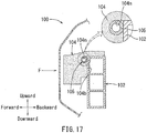
- the vehicle bumper 100 described in JP2016-37206A has a beam-shaped bumper reinforcement member 102 connected to a vehicle body, and a cushioning material of a bumper absorber 104 positioned in front of the bumper reinforcement member 102.
- the bumper absorber 104 has a tube receiving groove 104m extending in a vehicle width direction.
- the tube receiving groove 104m is formed on an upper portion of a rear end surface 104b of the bumper absorber 104, which surface is configured to contact an upper portion of a front surface of the bumper reinforcement member 102.
- an elastically deformable airtight pressure tube 105 which communicates with a pressure sensor, is received in the tube receiving groove 104m of the bumper absorber 104.
- the bumper absorber 104 when a collision load F is applied to the vehicle bumper 100, the bumper absorber 104 may be compressed in front of the bumper reinforcement member 102, so that the collision load F is absorbed to some degree. Further, the airtight pressure tube 105 is compressed between the bumper absorber 104 and the bumper reinforcement member 102. A pressure increase within the pressure tube 105 is detected by the pressure sensor. Thus, the application of the collision load F to the vehicle bumper 100 is detected, so that a pop-up hood system or other such system is activated in order to protect a pedestrian.
- the collision load F may be obliquely applied to the vehicle bumper 100 from before and above.
- the collision load F may be substantially horizontally applied to the vehicle bumper.
- the pressure tube 105 is received in the tube receiving groove 104m formed in the rear end surface 104b of the bumper absorber 104, which surface is configured to contact the upper portion of the front surface of the bumper reinforcement member 102. Therefore, the pressure tube 105 may be compressed regardless of whether the collision load F is obliquely applied to the vehicle bumper 100 from before and above as due to a collision with the pedestrian or whether the collision load F is horizontally applied to the vehicle bumper 100 as due to a collision with the small animal or other such object. This may lead to an increased level of difficulty for determining whether the pedestrian collides with the vehicle bumper 100 or whether the small animal or other such object collides with the vehicle bumper 100.
- a vehicle bumper may include a bumper reinforcement member connected to a vehicle body, a bumper absorber functioning as a cushioning member that covers the bumper reinforcement member and having a tube receiving groove that extends in a vehicle width direction, an elastically deformable pressure tube received in the tube receiving groove formed on the bumper absorber and in communication with a pressure sensor, and a bumper cover covering the bumper absorber and the bumper reinforcement member.
- the bumper absorber includes a beam-shaped absorber body portion extending in the vehicle width direction and an elongated projecting portion defining an upper portion of a load receiving surface of the absorber body portion and extending in the vehicle width direction at an end periphery of an upper surface of the absorber body portion.
- the tube receiving groove is configured to extend in the vehicle width direction on the upper surface of the absorber body portion while penetrating into an end portion of the elongated projecting portion that is positioned opposite to the load receiving surface, and is configured to open in a direction away from the load receiving surface.
- the tube receiving groove in which the pressure tube is received, is configured to extend in the vehicle width direction on the upper surface of the absorber body portion while penetrating into the end portion of the elongated projecting portion that is positioned opposite to the load receiving surface, and is configured to open in the direction away from the load receiving surface. Therefore, when a collision load is obliquely applied to the vehicle bumper from before and above, due to a collision of a pedestrian against the vehicle bumper, the elongated projecting portion of the bumper absorber may be compressed while being bent backward and downward about the tube receiving groove serving as a base point, so that the pressure tube received in the tube receiving groove may be compressed.
- the absorber body portion of the bumper absorber may be horizontally compressed.
- the elongated projecting portion may substantially be prevented from being deformed, so that the tube receiving groove may be maintained in a condition in which it opens backward. Therefore, the tube sensor may substantially be prevented from being compressed.
- the pressure tube may be easily compressed, whereas when the small animal or other such object collides with the vehicle bumper, the pressure tube may be prevented from being easily compressed. This may lead to an increased degree of accuracy of determining whether the pedestrian collides with the vehicle bumper or whether the small animal or other such object collides with the vehicle bumper.
- side walls of the tube receiving groove are sloped downward toward the load receiving surface.
- An opening of the tube receiving groove is obliquely directed upward.
- a side wall of the tube receiving groove is flush with the upper surface of the absorber body portion.
- An opening of the tube receiving groove is directed in a direction away from the load receiving surface.
- the bumper absorber has a recessed portion formed in the load receiving surface thereof and extending in the vehicle width direction.
- the recessed portion is configured to function as a bend-promoting point when the elongated projecting portion is bent due to the collision load.
- a pressing portion is disposed between the bumper cover and the load receiving surface of the bumper absorber at a position corresponding to the elongated projecting portion of the bumper absorber.
- the absorber body portion has an end surface that contacts the bumper reinforcement member when the collision load is applied thereto.
- a plurality of hole portions having a predetermined depth are formed in the end surface of the absorber body portion at a certain distance in the vehicle width direction.
- a plate-shaped projecting member extending in the vehicle width direction is formed in the load receiving surface of the absorber body portion.
- the projecting member formed in a front surface of the absorber body portion of the bumper absorber may be initially compressed, so that the elongated projecting portion may be prevented from being bent.
- the pressure tube received in the tube receiving groove may substantially be prevented from being compressed.
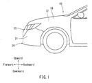
- the vehicle bumper according to this embodiment may be a front bumper 20 of a passenger vehicle 10 shown in FIG. 1 . Further, forward, backward, rightward, leftward, upward and downward directions described with reference to the figures may respectively correspond to forward, backward, rightward, leftward, upward and downward directions of the passenger vehicle 10 having the front bumper 20 according to the embodiment.
- the passenger vehicle 10 may have a pair of front side members 14 positioned on a front portion of a vehicle body and extending in a vehicle front-back direction.
- the front side members 14 may respectively be positioned on right and left sides of an engine compartment.
- the right and left front side members 14 may respectively have crushable boxes 16 that are respectively substantially axially attached to front end portions thereof. Further, the right and left crushable boxes 16 may respectively connected to right and left end portions of the front bumper 20.
- the crushable boxes 16 may be configured to be crushed between the front bumper 20 and the front side members 14 in the event of a frontal collision of the passenger vehicle 10, so as to absorb a collision load.
- the front bumper 20 may include a bumper reinforcement member 40, a bumper absorber 30, a bumper cover 21 with a bumper grill 23, and a tube sensor 50 of a pedestrian-collision detection device (not shown).
- the bumper reinforcement member 40 may be a beam-shaped member extending in a vehicle width direction. Right and left end portions of the bumper reinforcement member 40 may be connected to the right and left crushable boxes 16.
- the bumper reinforcement member 40 may be made of, for example, an aluminum alloy.
- the bumper reinforcement member 40 may have an upper rectangular cylindrical portion 41 and a lower rectangular cylindrical portion 43 that are vertically positioned.
- the bumper absorber 30 may be attached to a front surface 41f of the upper rectangular cylindrical portion 41 of the bumper reinforcement member 40.
- the bumper absorber 30 may be a cushioning member made of, for example, foamed polystyrene.
- the bumper absorber 30 may be composed of a rectangular beam-shaped absorber body portion 31 extending in the vehicle width direction, and a rectangular elongated projecting portion 33 positioned on a front end periphery of an upper surface 31u of the absorber body portion 31 and extending in the vehicle width direction, and may be formed into a substantially L-shape in cross section.
- the absorber body portion 31 and the elongated projecting portion 33 may be configured such that front surfaces 31f and 33f thereof are flush with each other. Further, the front surface 31f of the absorber body portion 31 and the front surface 33f of the elongated projecting portion 33 may function as a load receiving surface by which the collision load F is received. Further, the absorber body portion 31 may be positioned such that a rear end surface 31b thereof may cover the entire area of the front surface 41f of the upper rectangular cylindrical portion 41 of the bumper reinforcement member 40 in the vehicle width direction.
- a tube receiving groove 32 in which the tube sensor 50 is received, may be formed on the bumper absorber 30 at a boundary portion between the elongated projecting portion 33 and the upper surface 31u of the absorber body portion 31.
- the tube receiving groove 32 may be configured to extend in the vehicle width direction.
- the tube receiving groove 32 may be formed in the upper surface 31u of the absorber body portion 31 while penetrating into a rear end portion of the elongated projecting portion 33.
- the tube receiving groove 32 may be configured to extend in the vehicle width direction and be configured to open backward.
- the tube receiving groove 32 may be a groove having a rectangular shape in cross section and having a width and a depth each of which is substantially equal to an outer diameter of the tube sensor 50.
- the tube receiving groove 32 may be formed such that a pair of side walls 32w configured to diametrically sandwich the tube sensor 50 are sloped forward and downward. That is, the tube receiving groove 32 may be configured such that an opening thereof is obliquely directed backward and upward.
- the tube sensor 50 may be an elastically deformable airtight tube. As shown in FIG. 3 , one end (the left end) and the other end (the right end) of the tube sensor 50 may respectively communicate with pressure sensors 52. That is, the tube sensor 50 may be configured such that a pressure within the tube sensor 50 is detected by the right and left pressure sensors 52. Further, an intermediate portion of the tube sensor 50 positioned between the right and left pressure sensors 52 may be received in the tube receiving groove 32 of the bumper absorber 30. Further, the opening of the tube receiving groove 32 may be provided with holding strips (not labeled) in order to prevent the tube sensor 50 received in the tube receiving groove 32 from exiting the tube receiving groove 32. Output signals of the right and left pressure sensors 52 may be input into the pedestrian-collision detection device. Further, the tube sensor 50 may also be referred to as a pressure tube elsewhere in this disclosure.
- the bumper cover 21 may be a member defining a designing profile of the front bumper 20 and may be configured to cover the bumper absorber 30 and the bumper reinforcement member 40. Further, as shown in FIG. 2 , an inner side of a lower end of the bumper cover 21 may be supported by a lower absorber 35. Further, the bumper cover 21 may be provided with an ornamental member of the bumper grill 23, which is positioned at a middle portion thereof. The bumper grill 23 may function as an air inlet. The bumper cover 21 with the bumper grill 23 may be referred to as a bumper cover in this disclosure.
- the bumper cover 21 with the bumper grill 23 may have a spacer member 22 that is attached to an inner wall surface of the bumper cover 21 at the same height as the bumper absorber 30.
- the spacer member 22 may be configured to close a clearance between the bumper cover 21 and the bumper absorber 30 and a clearance between the bumper grill 23 and the bumper absorber 30.
- the spacer member 22 may have a vertical wall surface 22w.
- the vertical wall surface 22w may be configured so as to be capable of contacting the front surface 31f of the absorber body portion 31 and the front surface 33f of the elongated projecting portion 33 in the bumper absorber 30.
- the vertical wall surface 22w of the spacer member 22 may be configured such that a vertical dimension thereof is greater than a vertical dimension of the front surfaces 31f and 33f of the bumper absorber 30.
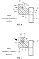
- the collision load F may be obliquely applied to the front bumper 20 from before and above. That is, as shown in FIG. 5 , the collision load F may be obliquely applied to the front surfaces 31f and 33f (the load receiving surface) of the bumper absorber 30 from before and above via the bumper cover 21, the bumper grill 23 and the vertical wall surface 22w of the spacer member 22. As a result, the elongated projecting portion 33 of the bumper absorber 30 may be compressed while being bent backward and downward about the tube receiving groove 32 serving as a base point, so that the tube sensor 50 received in the tube receiving groove 32 may be compressed.
- a pressure inside the tube sensor 50 may be increased.
- a pressure increase within the tube sensor 50 may be detected by the pressure sensor 52.
- the pedestrian-collision detection device may then activate, for example, a pop-up hood system, based on pressure signals from the pressure sensors 52.
- the hood 18 may be popped up, so that the pedestrian may be protected.
- the collision load F may be substantially horizontally applied to the front bumper 20. That is, as shown in FIG. 6 , the collision load F may be horizontally applied to the front surfaces 31f and 33f of the bumper absorber 30 via the bumper cover 21, the bumper grill 23 and the vertical wall surface 22w of the spacer member 22. As a result, the absorber body portion 31 of the bumper absorber 30 may be horizontally compressed. At this time, the elongated projecting portion 33 may substantially be prevented from being deformed, so that the tube receiving groove 32 may be maintained in a condition in which it opens backward. Therefore, the tube sensor 50 may substantially be avoid being compressed, so that the pressure inside the tube sensor 50 may substantially be prevented from being increased.
- the pedestrian-collision detection device may be prevented from erroneously determining that a collision with the small animal or other such object is a collision with the pedestrian. Therefore, the pedestrian-collision detection device may be prevented from erroneously activating the pop-up hood system.
- the tube receiving groove 32 in which the tube sensor 50 (the pressure tube) is received, may be formed on the bumper absorber 30 at the boundary portion between the elongated projecting portion 33 and the upper surface 31u of the absorber body portion 31, while opening backward. Therefore, when the collision load F is obliquely applied to the front bumper 20 from in front and above due to a collision of the pedestrian against the front bumper 20, the elongated projecting portion 33 of the bumper absorber 30 may be compressed while being bent backward and downward about the tube receiving groove 32 serving as the base point, so that the tube sensor 50 received in the tube receiving groove 32 may be compressed.
- the absorber body portion 31 of the bumper absorber 30 may be horizontally compressed.
- the elongated projecting portion 33 may substantially avoid being deformed, so that the tube receiving groove 32 may be maintained in a condition in which it opens backward. Therefore, the tube sensor 50 may substantially avoid being compressed.
- the tube sensor 50 may be easily compressed, whereas when the small animal or other such object collides with the front bumper 20, the tube sensor 50 may avoid being easily compressed. This may lead to an increased degree of accuracy of determining whether the pedestrian collides with the front bumper 20 or whether the small animal or other such object collides with the front bumper 20.
- the vertical wall surface 22w of the spacer member 22 may be configured so as to contact the front surfaces 31f and 33f (the load receiving surface) of the bumper absorber 30 over the entire area thereof.
- the spacer member 22 may have an upper projecting portion 22u and a lower projecting portion 22d positioned at a certain distance.
- the spacer member 22 thus modified may be positioned such that the upper projecting portion 22u corresponds to the elongated projecting portion 33 of the bumper absorber 30.
- the collision load F when the collision load F is obliquely applied to the front bumper 20 from before and above due to the collision of the pedestrian against the front bumper 20, the collision load may be further concentrated to the elongated projecting portion 33 of the bumper absorber 30 via the upper projecting portion 22u of the spacer member 22. This may allow the elongated projecting portion 33 to more easily bend backward and downward. As a result, the tube sensor 50 received in the tube receiving groove 32 may be more easily compressed. Further, the upper projecting portion 22u of the spacer member 22 may be referred to as a pressing portion in this disclosure.
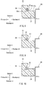
- the tube receiving groove 32 of the tube sensor 50 may be formed to have the rectangular shape in cross section. Further, the tube receiving groove 32 may be configured such that the opening thereof is obliquely directed backward and upward. However, as shown in FIG. 8 , the tube receiving groove 32 having the rectangular shape in cross section may be configured such that the lower side wall 32w is flush with the upper surface 31u of the absorber body portion 31. According to this modified embodiment, when the collision load F is horizontally applied to the front bumper 20, due to the collision of the small animal or other such object against the front bumper 20, the tube sensor 50 received in the tube receiving groove 32 may be further prevented from being compressed.
- the tube receiving groove 32 may have a triangular shape in cross section instead of the rectangular shape in cross section. According to this modified embodiment, when the collision load F is obliquely applied to the front bumper 20 from in front and above due to the collision of the pedestrian against the front bumper 20, the tube sensor 50 received in the tube receiving groove 32 may be more easily compressed.
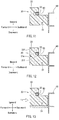
- the tube receiving groove 32 may be configured such that each of the width and the depth thereof is substantially equal to the outer diameter of the tube sensor 50. However, as shown by the broken lines in FIG. 11 , the depth of the tube receiving groove 32 may be further increased. According to the modified embodiment, when the collision load F is obliquely applied to the front bumper 20 from before and above, the elongated projecting portion 33 of the bumper absorber 30 may be easily bent backward and downward about the tube receiving groove 32 serving as the base point. As a result, the tube sensor 50 may be easily compressed.
- the bumper absorber 30 may be provided with a recessed portion 31m formed in the front surface 31f thereof instead of increasing the depth of the tube receiving groove 32 as shown in FIG. 11 .
- the recessed portion 31m may extend in the vehicle width direction.
- the recessed portion 31m may function as a bend-promoting point when the elongated projecting portion 33 is bent backward and downward.
- the absorber body portion 31 of the bumper absorber 30 may be uniformly increased in thickness relative to the elongated projecting portion 33 of the bumper absorber 30.
- the bumper absorber 30 when the collision load F is horizontally applied to the front bumper 20 due to the collision of the small animal or other such object against the front bumper 20, the bumper absorber 30 may be prevented from rotating upward or downward, so as to promote stable horizontal compression.
- the elongated projecting portion 33 may be prevented from being bent backward due to the collision load F being horizontally applied, so that the tube sensor 50 may be prevented from being compressed.
- the absorber body portion 31 of the bumper absorber 30 may be gradually increased in thickness from front to back instead of uniformly increasing the absorber body portion 31 in thickness as shown in FIG. 13 .
- the bumper absorber 30 may be provided with a plurality of hole portions 31x, each having a predetermined depth.
- the hole portions 31x may be formed in the rear end surface 31b of the absorber body portion 31 at a certain distance in the vehicle width direction.
- a rear end portion of the absorber body portion 31 of the bumper absorber 30 may be compressed before other portions, so that the elongated projecting portion 33 may be prevented from being bent backward. Therefore, the tube receiving groove 32 formed on the bumper absorber 30 may substantially be prevented from being deformed, so that the tube sensor 50 may be prevented from being compressed.
- a plate-shaped projecting member 31z having a predetermined thickness may be formed in the front surface 31f of the absorber body portion 31 of the bumper absorber 30.
- the projecting member 31z may be configured to extend in the vehicle width direction.
- the projecting portion 31z formed in the front surface 31f of the absorber body portion 31 may be compressed before other portions, so that the elongated projecting portion 33 may be prevented from being bent backward. Therefore, the tube receiving groove 32 formed on the bumper absorber 30 may substantially be prevented from being deformed, so that the tube sensor 50 may be prevented from being compressed.
- the bumper absorber 30 is attached to the front surface 41f of the upper rectangular cylindrical portion 41 of the bumper reinforcement member 40.
- the bumper absorber 30 may be attached to a front surface of the lower rectangular cylindrical portion 43.
- the bumper reinforcement member 40 may be composed of the upper rectangular cylindrical portion 41 and the lower rectangular cylindrical portion 43 that are vertically positioned.
- a bumper reinforcement member composed of a single rectangular cylindrical portion may be used.
- the front bumper 20 of the vehicle is shown as an example. However, the disclosure may also be applied to a rear bumper of the vehicle.
Abstract
Description
- The present disclosure relates to a vehicle bumper in which an elastically deformable airtight pressure tube, which communicates with a pressure sensor, is received in a tube receiving groove formed on a bumper absorber and extending in a vehicle width direction.
- A conventional art relating to a vehicle bumper is described in
JP2016-37206A FIG. 17 , thevehicle bumper 100 described inJP2016-37206A bumper reinforcement member 102 connected to a vehicle body, and a cushioning material of a bumper absorber 104 positioned in front of thebumper reinforcement member 102. Thebumper absorber 104 has atube receiving groove 104m extending in a vehicle width direction. Thetube receiving groove 104m is formed on an upper portion of arear end surface 104b of the bumper absorber 104, which surface is configured to contact an upper portion of a front surface of thebumper reinforcement member 102. Further, an elastically deformableairtight pressure tube 105, which communicates with a pressure sensor, is received in thetube receiving groove 104m of the bumper absorber 104. - According to the structure described above, when a collision load F is applied to the
vehicle bumper 100, the bumper absorber 104 may be compressed in front of thebumper reinforcement member 102, so that the collision load F is absorbed to some degree. Further, theairtight pressure tube 105 is compressed between the bumper absorber 104 and thebumper reinforcement member 102. A pressure increase within thepressure tube 105 is detected by the pressure sensor. Thus, the application of the collision load F to thevehicle bumper 100 is detected, so that a pop-up hood system or other such system is activated in order to protect a pedestrian. - For example, when a pedestrian collides with the
vehicle bumper 100, the legs of the pedestrian may contact thevehicle bumper 100, whereas the upper body of the pedestrian may fall against a hood. Therefore, the collision load F may be obliquely applied to thevehicle bumper 100 from before and above. Conversely, when a small animal or other such object collides with thevehicle bumper 100, the collision load F may be substantially horizontally applied to the vehicle bumper. - As described above, in the
vehicle bumper 100, thepressure tube 105 is received in thetube receiving groove 104m formed in therear end surface 104b of the bumper absorber 104, which surface is configured to contact the upper portion of the front surface of thebumper reinforcement member 102. Therefore, thepressure tube 105 may be compressed regardless of whether the collision load F is obliquely applied to thevehicle bumper 100 from before and above as due to a collision with the pedestrian or whether the collision load F is horizontally applied to thevehicle bumper 100 as due to a collision with the small animal or other such object. This may lead to an increased level of difficulty for determining whether the pedestrian collides with thevehicle bumper 100 or whether the small animal or other such object collides with thevehicle bumper 100. - Thus, there is a need in the art to provide an improved vehicle bumper.
- In a first aspect of the present disclosure, a vehicle bumper may include a bumper reinforcement member connected to a vehicle body, a bumper absorber functioning as a cushioning member that covers the bumper reinforcement member and having a tube receiving groove that extends in a vehicle width direction, an elastically deformable pressure tube received in the tube receiving groove formed on the bumper absorber and in communication with a pressure sensor, and a bumper cover covering the bumper absorber and the bumper reinforcement member. The bumper absorber includes a beam-shaped absorber body portion extending in the vehicle width direction and an elongated projecting portion defining an upper portion of a load receiving surface of the absorber body portion and extending in the vehicle width direction at an end periphery of an upper surface of the absorber body portion. The tube receiving groove is configured to extend in the vehicle width direction on the upper surface of the absorber body portion while penetrating into an end portion of the elongated projecting portion that is positioned opposite to the load receiving surface, and is configured to open in a direction away from the load receiving surface.
- According to this aspect, the tube receiving groove, in which the pressure tube is received, is configured to extend in the vehicle width direction on the upper surface of the absorber body portion while penetrating into the end portion of the elongated projecting portion that is positioned opposite to the load receiving surface, and is configured to open in the direction away from the load receiving surface. Therefore, when a collision load is obliquely applied to the vehicle bumper from before and above, due to a collision of a pedestrian against the vehicle bumper, the elongated projecting portion of the bumper absorber may be compressed while being bent backward and downward about the tube receiving groove serving as a base point, so that the pressure tube received in the tube receiving groove may be compressed. Conversely, when the collision load is horizontally applied to the vehicle bumper, due to a collision of a small animal or other such object against the vehicle bumper, the absorber body portion of the bumper absorber may be horizontally compressed. At this time, the elongated projecting portion may substantially be prevented from being deformed, so that the tube receiving groove may be maintained in a condition in which it opens backward. Therefore, the tube sensor may substantially be prevented from being compressed. Thus, when the pedestrian collides with the vehicle bumper, the pressure tube may be easily compressed, whereas when the small animal or other such object collides with the vehicle bumper, the pressure tube may be prevented from being easily compressed. This may lead to an increased degree of accuracy of determining whether the pedestrian collides with the vehicle bumper or whether the small animal or other such object collides with the vehicle bumper.
- In a second aspect of the present disclosure, side walls of the tube receiving groove are sloped downward toward the load receiving surface. An opening of the tube receiving groove is obliquely directed upward.
- In a third aspect of the present disclosure, a side wall of the tube receiving groove is flush with the upper surface of the absorber body portion. An opening of the tube receiving groove is directed in a direction away from the load receiving surface. According to this aspect, when the collision load is horizontally applied to the vehicle bumper, due to the collision of the small animal or other such object against the vehicle bumper, the pressure tube received in the tube receiving groove may be prevented from being compressed. That is, the pressure tube may be compressed only when the pedestrian collides with the vehicle bumper.
- In a fourth aspect of the present disclosure, the bumper absorber has a recessed portion formed in the load receiving surface thereof and extending in the vehicle width direction. The recessed portion is configured to function as a bend-promoting point when the elongated projecting portion is bent due to the collision load. According to this aspect, when the collision load is obliquely applied to the vehicle bumper from before and above, due to the collision of the pedestrian against the vehicle bumper, the elongated projecting portion may be easily bent backward. As a result, the pressure tube received in the tube receiving groove may be more easily compressed
- In a fifth aspect of the present disclosure, a pressing portion is disposed between the bumper cover and the load receiving surface of the bumper absorber at a position corresponding to the elongated projecting portion of the bumper absorber. According to this aspect, when the collision load is obliquely applied to the vehicle bumper from before and above, due to the collision of the pedestrian against the vehicle bumper, the collision load may be concentrated to the elongated projecting portion of the bumper absorber via the pressing portion, so that the elongated projecting portion may be easily bent backward. As a result, the pressure tube received in the tube receiving groove may be easily compressed.
- In a sixth aspect of the present disclosure, the absorber body portion has an end surface that contacts the bumper reinforcement member when the collision load is applied thereto. A plurality of hole portions having a predetermined depth are formed in the end surface of the absorber body portion at a certain distance in the vehicle width direction. According to this aspect, when the collision load is horizontally applied to the vehicle bumper, due to the collision of the small animal or other such object against the vehicle bumper, a rear end portion of the absorber body portion of the bumper absorber may be initially compressed, so that the elongated projecting portion may be prevented from being bent backward. Therefore, when the small animal or other such object collides against the vehicle bumper, the pressure sensor received in the tube receiving groove may substantially be prevented from being compressed.
- In a seventh aspect of the present disclosure, a plate-shaped projecting member extending in the vehicle width direction is formed in the load receiving surface of the absorber body portion. According to this aspect, when the collision load is horizontally applied to the vehicle bumper, due to the collision of the small animal or other such object against the vehicle bumper, the projecting member formed in a front surface of the absorber body portion of the bumper absorber may be initially compressed, so that the elongated projecting portion may be prevented from being bent. As a result, the pressure tube received in the tube receiving groove may substantially be prevented from being compressed.
-
-
FIG. 1 is a side view of a vehicle having a vehicle bumper (front bumper) according toEmbodiment 1 of the present disclosure. -
FIG. 2 is a schematic cross-sectional view of the vehicle bumper according to the embodiment. -
FIG. 3 is a plan view of a bumper absorber, a bumper reinforcement member and various other components of the vehicle bumper (viewed in a direction of arrow III ofFIG. 2 ). -
FIG. 4 is a cross-sectional view of the bumper absorber and the bumper reinforcement member (the cross-sectional view taken along line IV-IV ofFIG. 3 ). -
FIG. 5 is a schematic side view showing a deformation condition of the bumper absorber at the moment a pedestrian collides with the vehicle bumper. -
FIG. 6 is a schematic side view showing a deformation condition of the bumper absorber at the moment a small animal or other such object collides with the vehicle bumper. -
FIG. 7 is a cross-sectional view of a vehicle bumper according to ModifiedEmbodiment 1. -
FIG. 8 is a cross-sectional view showing a bumper absorber of a vehicle bumper according to Modified Embodiment 2. -
FIG. 9 is a cross-sectional view showing a bumper absorber of a vehicle bumper according to Modified Embodiment 3. -
FIG. 10 is a cross-sectional view showing a bumper absorber of a vehicle bumper according to Modified Embodiment 3. -
FIG. 11 is a cross-sectional view showing a bumper absorber of a vehicle bumper according to Modified Embodiment 4. -
FIG. 12 is a cross-sectional view showing a bumper absorber of a vehicle bumper according to Modified Embodiment 5. -
FIG. 13 is a cross-sectional view showing a bumper absorber of a vehicle bumper according to Modified Embodiment 6. -
FIG. 14 is a cross-sectional view showing a bumper absorber of a vehicle bumper according to Modified Embodiment 6. -
FIG. 15 is a cross-sectional view showing a bumper absorber of a vehicle bumper according to Modified Embodiment 7. -
FIG. 16 is a cross-sectional view showing a bumper absorber of a vehicle bumper according to Modified Embodiment 8. -
FIG. 17 is a cross-sectional view of a conventional vehicle bumper. - In the following, a vehicle bumper according to an
Embodiment 1 of the present disclosure will be described with reference toFIG. 1 to FIG. 16 . The vehicle bumper according to this embodiment may be afront bumper 20 of apassenger vehicle 10 shown inFIG. 1 . Further, forward, backward, rightward, leftward, upward and downward directions described with reference to the figures may respectively correspond to forward, backward, rightward, leftward, upward and downward directions of thepassenger vehicle 10 having thefront bumper 20 according to the embodiment. - A front structure of the
passenger vehicle 10 will be briefly described prior to providing a description of thefront bumper 20. As shown inFIG. 3 , thepassenger vehicle 10 may have a pair offront side members 14 positioned on a front portion of a vehicle body and extending in a vehicle front-back direction. Thefront side members 14 may respectively be positioned on right and left sides of an engine compartment. The right and leftfront side members 14 may respectively havecrushable boxes 16 that are respectively substantially axially attached to front end portions thereof. Further, the right and leftcrushable boxes 16 may respectively connected to right and left end portions of thefront bumper 20. Thecrushable boxes 16 may be configured to be crushed between thefront bumper 20 and thefront side members 14 in the event of a frontal collision of thepassenger vehicle 10, so as to absorb a collision load. - As shown in
FIG. 2 , thefront bumper 20 may include abumper reinforcement member 40, abumper absorber 30, abumper cover 21 with abumper grill 23, and atube sensor 50 of a pedestrian-collision detection device (not shown). As shown inFIG. 3 , thebumper reinforcement member 40 may be a beam-shaped member extending in a vehicle width direction. Right and left end portions of thebumper reinforcement member 40 may be connected to the right and leftcrushable boxes 16. Thebumper reinforcement member 40 may be made of, for example, an aluminum alloy. Further, as shown inFIG. 2 , thebumper reinforcement member 40 may have an upper rectangularcylindrical portion 41 and a lower rectangularcylindrical portion 43 that are vertically positioned. - As shown in
FIG. 2 andFIG. 3 , thebumper absorber 30 may be attached to afront surface 41f of the upper rectangularcylindrical portion 41 of thebumper reinforcement member 40. Thebumper absorber 30 may be a cushioning member made of, for example, foamed polystyrene. As shown inFIG. 3 andFIG. 4 , thebumper absorber 30 may be composed of a rectangular beam-shapedabsorber body portion 31 extending in the vehicle width direction, and a rectangular elongated projectingportion 33 positioned on a front end periphery of anupper surface 31u of theabsorber body portion 31 and extending in the vehicle width direction, and may be formed into a substantially L-shape in cross section. Further, theabsorber body portion 31 and the elongated projectingportion 33 may be configured such thatfront surfaces front surface 31f of theabsorber body portion 31 and thefront surface 33f of the elongated projectingportion 33 may function as a load receiving surface by which the collision load F is received. Further, theabsorber body portion 31 may be positioned such that arear end surface 31b thereof may cover the entire area of thefront surface 41f of the upper rectangularcylindrical portion 41 of thebumper reinforcement member 40 in the vehicle width direction. - A
tube receiving groove 32, in which thetube sensor 50 is received, may be formed on thebumper absorber 30 at a boundary portion between the elongated projectingportion 33 and theupper surface 31u of theabsorber body portion 31. Thetube receiving groove 32 may be configured to extend in the vehicle width direction. In particular, thetube receiving groove 32 may be formed in theupper surface 31u of theabsorber body portion 31 while penetrating into a rear end portion of the elongated projectingportion 33. Thetube receiving groove 32 may be configured to extend in the vehicle width direction and be configured to open backward. As shown inFIG. 4 , thetube receiving groove 32 may be a groove having a rectangular shape in cross section and having a width and a depth each of which is substantially equal to an outer diameter of thetube sensor 50. Thetube receiving groove 32 may be formed such that a pair ofside walls 32w configured to diametrically sandwich thetube sensor 50 are sloped forward and downward. That is, thetube receiving groove 32 may be configured such that an opening thereof is obliquely directed backward and upward. - The
tube sensor 50 may be an elastically deformable airtight tube. As shown inFIG. 3 , one end (the left end) and the other end (the right end) of thetube sensor 50 may respectively communicate withpressure sensors 52. That is, thetube sensor 50 may be configured such that a pressure within thetube sensor 50 is detected by the right and leftpressure sensors 52. Further, an intermediate portion of thetube sensor 50 positioned between the right and leftpressure sensors 52 may be received in thetube receiving groove 32 of thebumper absorber 30. Further, the opening of thetube receiving groove 32 may be provided with holding strips (not labeled) in order to prevent thetube sensor 50 received in thetube receiving groove 32 from exiting thetube receiving groove 32. Output signals of the right and leftpressure sensors 52 may be input into the pedestrian-collision detection device. Further, thetube sensor 50 may also be referred to as a pressure tube elsewhere in this disclosure. - As shown in
FIG. 1 ,FIG. 2 and other figures, thebumper cover 21 may be a member defining a designing profile of thefront bumper 20 and may be configured to cover thebumper absorber 30 and thebumper reinforcement member 40. Further, as shown inFIG. 2 , an inner side of a lower end of thebumper cover 21 may be supported by alower absorber 35. Further, thebumper cover 21 may be provided with an ornamental member of thebumper grill 23, which is positioned at a middle portion thereof. Thebumper grill 23 may function as an air inlet. Thebumper cover 21 with thebumper grill 23 may be referred to as a bumper cover in this disclosure. - As shown in
FIG. 2 , in thefront bumper 20, thebumper cover 21 with thebumper grill 23 may have aspacer member 22 that is attached to an inner wall surface of thebumper cover 21 at the same height as thebumper absorber 30. Thespacer member 22 may be configured to close a clearance between thebumper cover 21 and thebumper absorber 30 and a clearance between thebumper grill 23 and thebumper absorber 30. As shown inFIG. 2 , thespacer member 22 may have avertical wall surface 22w. Thevertical wall surface 22w may be configured so as to be capable of contacting thefront surface 31f of theabsorber body portion 31 and thefront surface 33f of the elongated projectingportion 33 in thebumper absorber 30. Further, thevertical wall surface 22w of thespacer member 22 may be configured such that a vertical dimension thereof is greater than a vertical dimension of thefront surfaces bumper absorber 30. - Next, an operation of the
front bumper 20 at the moment a pedestrian collides with thefront bumper 20 will be described. When the pedestrian collides with thefront bumper 20, the legs of the pedestrian may contact thefront bumper 20 and the upper body of the pedestrian may fall against ahood 18. Therefore, the collision load F may be obliquely applied to thefront bumper 20 from before and above. That is, as shown inFIG. 5 , the collision load F may be obliquely applied to thefront surfaces bumper absorber 30 from before and above via thebumper cover 21, thebumper grill 23 and thevertical wall surface 22w of thespacer member 22. As a result, the elongated projectingportion 33 of thebumper absorber 30 may be compressed while being bent backward and downward about thetube receiving groove 32 serving as a base point, so that thetube sensor 50 received in thetube receiving groove 32 may be compressed. - Consequently, a pressure inside the
tube sensor 50 may be increased. A pressure increase within thetube sensor 50 may be detected by thepressure sensor 52. The pedestrian-collision detection device may then activate, for example, a pop-up hood system, based on pressure signals from thepressure sensors 52. Thus, thehood 18 may be popped up, so that the pedestrian may be protected. - Conversely, when a small animal or other such object collides with the
vehicle bumper 100, the collision load F may be substantially horizontally applied to thefront bumper 20. That is, as shown inFIG. 6 , the collision load F may be horizontally applied to thefront surfaces bumper absorber 30 via thebumper cover 21, thebumper grill 23 and thevertical wall surface 22w of thespacer member 22. As a result, theabsorber body portion 31 of thebumper absorber 30 may be horizontally compressed. At this time, the elongated projectingportion 33 may substantially be prevented from being deformed, so that thetube receiving groove 32 may be maintained in a condition in which it opens backward. Therefore, thetube sensor 50 may substantially be avoid being compressed, so that the pressure inside thetube sensor 50 may substantially be prevented from being increased. Thus, the pedestrian-collision detection device may be prevented from erroneously determining that a collision with the small animal or other such object is a collision with the pedestrian. Therefore, the pedestrian-collision detection device may be prevented from erroneously activating the pop-up hood system. - According to the
front bumper 20 of the present embodiment, thetube receiving groove 32, in which the tube sensor 50 (the pressure tube) is received, may be formed on thebumper absorber 30 at the boundary portion between the elongated projectingportion 33 and theupper surface 31u of theabsorber body portion 31, while opening backward. Therefore, when the collision load F is obliquely applied to thefront bumper 20 from in front and above due to a collision of the pedestrian against thefront bumper 20, the elongated projectingportion 33 of thebumper absorber 30 may be compressed while being bent backward and downward about thetube receiving groove 32 serving as the base point, so that thetube sensor 50 received in thetube receiving groove 32 may be compressed. Conversely, when the collision load F is horizontally applied to thefront bumper 20 due to a collision of the small animal or other such object against thefront bumper 20, theabsorber body portion 31 of thebumper absorber 30 may be horizontally compressed. At this time, the elongated projectingportion 33 may substantially avoid being deformed, so that thetube receiving groove 32 may be maintained in a condition in which it opens backward. Therefore, thetube sensor 50 may substantially avoid being compressed. Thus, when the pedestrian collides with thefront bumper 20, thetube sensor 50 may be easily compressed, whereas when the small animal or other such object collides with thefront bumper 20, thetube sensor 50 may avoid being easily compressed. This may lead to an increased degree of accuracy of determining whether the pedestrian collides with thefront bumper 20 or whether the small animal or other such object collides with thefront bumper 20. - The embodiment described above can be changed or modified without departing from the scope of the disclosure. For example, as shown in
FIG. 2 , in the embodiment, thevertical wall surface 22w of thespacer member 22 may be configured so as to contact thefront surfaces bumper absorber 30 over the entire area thereof. However, as shown inFIG. 7 , thespacer member 22 may have an upper projectingportion 22u and a lower projectingportion 22d positioned at a certain distance. Thespacer member 22 thus modified may be positioned such that the upper projectingportion 22u corresponds to the elongated projectingportion 33 of thebumper absorber 30. Accordingly, when the collision load F is obliquely applied to thefront bumper 20 from before and above due to the collision of the pedestrian against thefront bumper 20, the collision load may be further concentrated to the elongated projectingportion 33 of thebumper absorber 30 via the upper projectingportion 22u of thespacer member 22. This may allow the elongated projectingportion 33 to more easily bend backward and downward. As a result, thetube sensor 50 received in thetube receiving groove 32 may be more easily compressed. Further, the upper projectingportion 22u of thespacer member 22 may be referred to as a pressing portion in this disclosure. - As shown in
FIG. 4 ,FIG. 7 and other figures, in the embodiment, thetube receiving groove 32 of thetube sensor 50 may be formed to have the rectangular shape in cross section. Further, thetube receiving groove 32 may be configured such that the opening thereof is obliquely directed backward and upward. However, as shown inFIG. 8 , thetube receiving groove 32 having the rectangular shape in cross section may be configured such that thelower side wall 32w is flush with theupper surface 31u of theabsorber body portion 31. According to this modified embodiment, when the collision load F is horizontally applied to thefront bumper 20, due to the collision of the small animal or other such object against thefront bumper 20, thetube sensor 50 received in thetube receiving groove 32 may be further prevented from being compressed. - As shown in
FIG. 9 and FIG. 10 , thetube receiving groove 32 may have a triangular shape in cross section instead of the rectangular shape in cross section. According to this modified embodiment, when the collision load F is obliquely applied to thefront bumper 20 from in front and above due to the collision of the pedestrian against thefront bumper 20, thetube sensor 50 received in thetube receiving groove 32 may be more easily compressed. - Further, in the embodiment, the
tube receiving groove 32 may be configured such that each of the width and the depth thereof is substantially equal to the outer diameter of thetube sensor 50. However, as shown by the broken lines inFIG. 11 , the depth of thetube receiving groove 32 may be further increased. According to the modified embodiment, when the collision load F is obliquely applied to thefront bumper 20 from before and above, the elongated projectingportion 33 of thebumper absorber 30 may be easily bent backward and downward about thetube receiving groove 32 serving as the base point. As a result, thetube sensor 50 may be easily compressed. - Further, as shown in
FIG. 12 , thebumper absorber 30 may be provided with a recessedportion 31m formed in thefront surface 31f thereof instead of increasing the depth of thetube receiving groove 32 as shown inFIG. 11 . The recessedportion 31m may extend in the vehicle width direction. The recessedportion 31m may function as a bend-promoting point when the elongated projectingportion 33 is bent backward and downward. - Further, as shown in
FIG. 13 , theabsorber body portion 31 of thebumper absorber 30 may be uniformly increased in thickness relative to the elongated projectingportion 33 of thebumper absorber 30. According to this modified embodiment, when the collision load F is horizontally applied to thefront bumper 20 due to the collision of the small animal or other such object against thefront bumper 20, thebumper absorber 30 may be prevented from rotating upward or downward, so as to promote stable horizontal compression. According to this modified embodiment, the elongated projectingportion 33 may be prevented from being bent backward due to the collision load F being horizontally applied, so that thetube sensor 50 may be prevented from being compressed. Alternatively, as shown inFIG. 14 , theabsorber body portion 31 of thebumper absorber 30 may be gradually increased in thickness from front to back instead of uniformly increasing theabsorber body portion 31 in thickness as shown inFIG. 13 . - Further, as shown in
FIG. 15 , thebumper absorber 30 may be provided with a plurality ofhole portions 31x, each having a predetermined depth. Thehole portions 31x may be formed in therear end surface 31b of theabsorber body portion 31 at a certain distance in the vehicle width direction. According to this modified embodiment, when the collision load F is horizontally applied to the front bumper, a rear end portion of theabsorber body portion 31 of thebumper absorber 30 may be compressed before other portions, so that the elongated projectingportion 33 may be prevented from being bent backward. Therefore, thetube receiving groove 32 formed on thebumper absorber 30 may substantially be prevented from being deformed, so that thetube sensor 50 may be prevented from being compressed. - Further, as shown in
FIG. 16 , a plate-shaped projectingmember 31z having a predetermined thickness may be formed in thefront surface 31f of theabsorber body portion 31 of thebumper absorber 30. The projectingmember 31z may be configured to extend in the vehicle width direction. According to this modified embodiment, when the collision load F is horizontally applied to the front bumper, the projectingportion 31z formed in thefront surface 31f of theabsorber body portion 31 may be compressed before other portions, so that the elongated projectingportion 33 may be prevented from being bent backward. Therefore, thetube receiving groove 32 formed on thebumper absorber 30 may substantially be prevented from being deformed, so that thetube sensor 50 may be prevented from being compressed. - Further, in the embodiment, the
bumper absorber 30 is attached to thefront surface 41f of the upper rectangularcylindrical portion 41 of thebumper reinforcement member 40. However, thebumper absorber 30 may be attached to a front surface of the lower rectangularcylindrical portion 43. Further, in the embodiment, thebumper reinforcement member 40 may be composed of the upper rectangularcylindrical portion 41 and the lower rectangularcylindrical portion 43 that are vertically positioned. However, a bumper reinforcement member composed of a single rectangular cylindrical portion may be used. Further, in the embodiment, thefront bumper 20 of the vehicle is shown as an example. However, the disclosure may also be applied to a rear bumper of the vehicle.
Claims (7)
- A vehicle bumper comprising a bumper reinforcement member connected to a vehicle body, a bumper absorber functioning as a cushioning member that covers the bumper reinforcement member and having a tube receiving groove that extends in a vehicle width direction, an elastically deformable pressure tube received in the tube receiving groove formed on the bumper absorber and in communication with a pressure sensor, and a bumper cover covering the bumper absorber and the bumper reinforcement member,
wherein the bumper absorber includes a beam-shaped absorber body portion extending in the vehicle width direction, and an elongated projecting portion defining an upper portion of a load receiving surface of the absorber body portion and extending in the vehicle width direction at an end periphery of an upper surface of the absorber body portion, and
wherein the tube receiving groove is configured to extend in the vehicle width direction on the upper surface of the absorber body portion while penetrating into an end portion of the elongated projecting portion that is positioned opposite to the load receiving surface, and is configured to open in a direction away from the load receiving surface. - The vehicle bumper as described in claim 1, wherein side walls of the tube receiving groove are sloped downward toward the load receiving surface, and wherein an opening of the tube receiving groove is obliquely directed upward.
- The vehicle bumper as described in claim 1, wherein a side wall of the tube receiving groove is flush with the upper surface of the absorber body portion, and wherein an opening of the tube receiving groove is directed in a direction away from the load receiving surface.
- The vehicle bumper as described in any one of claim 1 to claim 3, wherein the bumper absorber has a recessed portion formed in the load receiving surface thereof and extending in the vehicle width direction, and wherein the recessed portion is configured to function as a bend-promoting point when the elongated projecting portion is bent due to a collision load.
- The vehicle bumper as described in any one of claim 1 to claim 4, wherein a pressing portion is disposed between the bumper cover and the load receiving surface of the bumper absorber at a position corresponding to the elongated projecting portion of the bumper absorber.
- The vehicle bumper as described in any one of claim 1 to claim 5, wherein the absorber body portion has an end surface that contacts the bumper reinforcement member when the collision load is applied thereto, and wherein a plurality of hole portions having a predetermined depth are formed in the end surface of the absorber body portion at a certain distance in the vehicle width direction.
- The vehicle bumper as described in any one of claim 1 to claim 6, wherein a plate-shaped projecting member extending in the vehicle width direction is formed in the load receiving surface of the absorber body portion.
Applications Claiming Priority (2)
| Application Number | Priority Date | Filing Date | Title |
|---|---|---|---|
| JP2017158487A JP6766776B2 (en) | 2017-08-21 | 2017-08-21 | Vehicle bumper |
| PCT/JP2018/026494 WO2019039133A1 (en) | 2017-08-21 | 2018-07-13 | Vehicle bumper |
Publications (2)
| Publication Number | Publication Date |
|---|---|
| EP3674148A1 true EP3674148A1 (en) | 2020-07-01 |
| EP3674148A4 EP3674148A4 (en) | 2021-03-24 |
Family
ID=65438702
Family Applications (1)
| Application Number | Title | Priority Date | Filing Date |
|---|---|---|---|
| EP18847538.8A Withdrawn EP3674148A4 (en) | 2017-08-21 | 2018-07-13 | Vehicle bumper |
Country Status (5)
| Country | Link |
|---|---|
| US (1) | US11052846B2 (en) |
| EP (1) | EP3674148A4 (en) |
| JP (1) | JP6766776B2 (en) |
| CN (1) | CN110891828B (en) |
| WO (1) | WO2019039133A1 (en) |
Families Citing this family (4)
| Publication number | Priority date | Publication date | Assignee | Title |
|---|---|---|---|---|
| JP6760873B2 (en) * | 2017-03-24 | 2020-09-23 | 株式会社神戸製鋼所 | Vehicle structure |
| JP6806922B2 (en) * | 2017-10-24 | 2021-01-06 | 本田技研工業株式会社 | Collision detection structure |
| JP7264736B2 (en) * | 2019-06-11 | 2023-04-25 | 本田技研工業株式会社 | Collision detection system |
| US11491936B2 (en) * | 2020-03-02 | 2022-11-08 | Subaru Corporation | Collision detection device |
Family Cites Families (36)
| Publication number | Priority date | Publication date | Assignee | Title |
|---|---|---|---|---|
| US3926462A (en) * | 1974-10-11 | 1975-12-16 | Gen Motors Corp | Shock absorbing buffer assembly |
| DE3035164C2 (en) * | 1980-09-18 | 1986-12-11 | Daimler-Benz Ag, 7000 Stuttgart | Bumpers for motor vehicles |
| DE3125650A1 (en) * | 1981-06-30 | 1983-01-27 | Daimler-Benz Ag, 7000 Stuttgart | "BUMPER FOR A VEHICLE" |
| JPH04303046A (en) * | 1991-03-29 | 1992-10-27 | Aisin Seiki Co Ltd | Bumper device for vehicle |
| DE4237707C2 (en) * | 1992-11-07 | 2000-05-25 | Daimler Chrysler Ag | Via at least one support element on a part fixed to the vehicle by means of a screw connection, bumper of a motor vehicle |
| US7226097B2 (en) * | 2002-09-30 | 2007-06-05 | Sekisui Kaseihin Kogyo Kabushiki Kaisha | Bumper absorber for pedestrain protection |
| KR100517904B1 (en) * | 2003-06-27 | 2005-10-05 | 한화종합화학 주식회사 | Bumper System |
| JP4052244B2 (en) * | 2003-12-24 | 2008-02-27 | トヨタ自動車株式会社 | Bumper structure for vehicles |
| JP2006125989A (en) * | 2004-10-28 | 2006-05-18 | Denso Corp | Load sensor, load detection method of load sensor, and pedestrian protection system |
| JP2007192577A (en) * | 2006-01-17 | 2007-08-02 | Denso Corp | Collision object discriminating device |
| JP4440896B2 (en) * | 2006-02-15 | 2010-03-24 | トヨタ自動車株式会社 | Bumper structure for vehicles |
| JP4324172B2 (en) * | 2006-02-15 | 2009-09-02 | トヨタ自動車株式会社 | Bumper structure for vehicles |
| JP4466690B2 (en) * | 2007-07-17 | 2010-05-26 | 株式会社デンソー | Collision detection device |
| JP2009023407A (en) * | 2007-07-17 | 2009-02-05 | Denso Corp | Collision detector |
| JP2009023405A (en) * | 2007-07-17 | 2009-02-05 | Denso Corp | Collision detection sensor |
| JP5302643B2 (en) * | 2008-12-02 | 2013-10-02 | 株式会社デンソー | Collision detection device and collision detection method |
| US20150115632A1 (en) * | 2013-10-31 | 2015-04-30 | Shape Corp. | Bumper beam with rod reinforced face |
| JP5924548B2 (en) * | 2013-11-26 | 2016-05-25 | 株式会社デンソー | Vehicle collision detection device |
| JP6032214B2 (en) * | 2014-01-09 | 2016-11-24 | トヨタ自動車株式会社 | Bumper structure for vehicles |
| JP6090196B2 (en) * | 2014-02-10 | 2017-03-08 | トヨタ自動車株式会社 | Bumper structure for vehicles with pedestrian collision detection sensor |
| JP6201909B2 (en) * | 2014-06-18 | 2017-09-27 | 株式会社デンソー | Vehicle collision detection device |
| JP6079712B2 (en) * | 2014-07-24 | 2017-02-15 | トヨタ自動車株式会社 | Bumper for vehicle |
| JP6098897B2 (en) * | 2014-08-08 | 2017-03-22 | 株式会社デンソー | Vehicle collision detection device |
| JP6146383B2 (en) | 2014-08-08 | 2017-06-14 | トヨタ自動車株式会社 | Bumper structure for vehicles with pressure tube type pedestrian collision detection sensor |
| JP6107784B2 (en) * | 2014-10-10 | 2017-04-05 | トヨタ自動車株式会社 | Bumper structure for vehicles with pedestrian collision detection sensor |
| JP6512544B2 (en) * | 2015-03-10 | 2019-05-15 | 株式会社Subaru | Collision detection device |
| JP6134972B2 (en) * | 2015-03-25 | 2017-05-31 | トヨタ自動車東日本株式会社 | Bumper structure |
| JP6418074B2 (en) * | 2015-06-16 | 2018-11-07 | トヨタ自動車株式会社 | Bumper structure for vehicles with pedestrian collision detection sensor |
| JP6428514B2 (en) * | 2015-07-08 | 2018-11-28 | 株式会社デンソー | Vehicle collision detection device |
| JP6369415B2 (en) * | 2015-07-28 | 2018-08-08 | 株式会社デンソー | Vehicle collision sensor and vehicle collision detection device using the same |
| JP6256427B2 (en) * | 2015-08-10 | 2018-01-10 | トヨタ自動車株式会社 | Bumper structure for vehicles with pedestrian collision detection sensor |
| JP2017100563A (en) * | 2015-12-02 | 2017-06-08 | 三菱自動車工業株式会社 | Vehicular pedestrian collision detection apparatus |
| JP2017100643A (en) * | 2015-12-04 | 2017-06-08 | 三菱自動車工業株式会社 | Vehicular pedestrian collision detection apparatus |
| JP6728077B2 (en) * | 2016-05-20 | 2020-07-22 | 株式会社神戸製鋼所 | Structural member |
| US9834164B1 (en) * | 2016-07-27 | 2017-12-05 | GM Global Technology Operations LLC | Impact sensor arrangements for active hood systems of motor vehicles |
| KR102642568B1 (en) * | 2019-09-27 | 2024-02-29 | 현대모비스 주식회사 | Pedestrians impact sensing device |
-
2017
- 2017-08-21 JP JP2017158487A patent/JP6766776B2/en active Active
-
2018
- 2018-07-13 CN CN201880046352.7A patent/CN110891828B/en active Active
- 2018-07-13 WO PCT/JP2018/026494 patent/WO2019039133A1/en unknown
- 2018-07-13 US US16/626,851 patent/US11052846B2/en active Active
- 2018-07-13 EP EP18847538.8A patent/EP3674148A4/en not_active Withdrawn
Also Published As
| Publication number | Publication date |
|---|---|
| WO2019039133A1 (en) | 2019-02-28 |
| JP2019034680A (en) | 2019-03-07 |
| US20200223384A1 (en) | 2020-07-16 |
| CN110891828B (en) | 2022-09-27 |
| CN110891828A (en) | 2020-03-17 |
| US11052846B2 (en) | 2021-07-06 |
| JP6766776B2 (en) | 2020-10-14 |
| EP3674148A4 (en) | 2021-03-24 |
Similar Documents
| Publication | Publication Date | Title |
|---|---|---|
| EP3674148A1 (en) | Vehicle bumper | |
| US9718423B2 (en) | Vehicle bumper structure including a pedestrian collision detection sensor | |
| US9663053B2 (en) | Collision detection device for vehicle | |
| US7868748B2 (en) | Collision detection sensor for vehicle | |
| EP2895357B1 (en) | Vehicle bumper including pedestrian collision detection apparatus | |
| WO2017122598A1 (en) | Collision detection device for vehicle | |
| US10668880B2 (en) | Collision detecting device for a motor vehicle for detecting a collision with a pedestrian | |
| JP2009023407A (en) | Collision detector | |
| JP2007269279A (en) | Collision detection system for vehicle | |
| JP5962435B2 (en) | Bumper for vehicle equipped with pedestrian collision detection device | |
| WO2016088328A1 (en) | Vehicle collision detection device | |
| JP2009040393A (en) | Vehicular collision detecting device | |
| JP2016165977A (en) | Collision detection device | |
| JP6294066B2 (en) | Pedestrian collision detection device | |
| JP5499907B2 (en) | Pedestrian collision detection device | |
| WO2016170733A1 (en) | Collision detection device for vehicle | |
| WO2016129251A1 (en) | Vehicle impact detection device | |
| WO2016136165A1 (en) | Collision detection device for vehicle | |
| JP2016088210A (en) | Vehicular bumper structure with pedestrian collision detection sensor | |
| JP5850018B2 (en) | Pedestrian collision detection sensor mounting structure | |
| JP5765243B2 (en) | Vehicle side collision detection mechanism and occupant protection system | |
| JP5381906B2 (en) | Vehicle collision detection device | |
| JP5994666B2 (en) | Bumper for vehicle equipped with pedestrian collision detection device | |
| JP6334337B2 (en) | Vehicle collision detection sensor mounting structure | |
| US20230096952A1 (en) | Collision detection apparatus |
Legal Events
| Date | Code | Title | Description |
|---|---|---|---|
| STAA | Information on the status of an ep patent application or granted ep patent |
Free format text: STATUS: THE INTERNATIONAL PUBLICATION HAS BEEN MADE |
|
| PUAI | Public reference made under article 153(3) epc to a published international application that has entered the european phase |
Free format text: ORIGINAL CODE: 0009012 |
|
| STAA | Information on the status of an ep patent application or granted ep patent |
Free format text: STATUS: REQUEST FOR EXAMINATION WAS MADE |
|
| 17P | Request for examination filed |
Effective date: 20200206 |
|
| AK | Designated contracting states |
Kind code of ref document: A1 Designated state(s): AL AT BE BG CH CY CZ DE DK EE ES FI FR GB GR HR HU IE IS IT LI LT LU LV MC MK MT NL NO PL PT RO RS SE SI SK SM TR |
|
| AX | Request for extension of the european patent |
Extension state: BA ME |
|
| DAV | Request for validation of the european patent (deleted) | ||
| DAX | Request for extension of the european patent (deleted) | ||
| A4 | Supplementary search report drawn up and despatched |
Effective date: 20210219 |
|
| RIC1 | Information provided on ipc code assigned before grant |
Ipc: B60R 19/18 20060101ALI20210215BHEP Ipc: B60R 19/48 20060101AFI20210215BHEP Ipc: B60R 21/0136 20060101ALI20210215BHEP |
|
| GRAP | Despatch of communication of intention to grant a patent |
Free format text: ORIGINAL CODE: EPIDOSNIGR1 |
|
| STAA | Information on the status of an ep patent application or granted ep patent |
Free format text: STATUS: GRANT OF PATENT IS INTENDED |
|
| INTG | Intention to grant announced |
Effective date: 20210518 |
|
| STAA | Information on the status of an ep patent application or granted ep patent |
Free format text: STATUS: THE APPLICATION IS DEEMED TO BE WITHDRAWN |
|
| 18D | Application deemed to be withdrawn |
Effective date: 20210929 |