EP3674094B1 - Nichtverdampfendes wässriges tintentrocknungssystem und -verfahren - Google Patents
Nichtverdampfendes wässriges tintentrocknungssystem und -verfahren Download PDFInfo
- Publication number
- EP3674094B1 EP3674094B1 EP19219927.1A EP19219927A EP3674094B1 EP 3674094 B1 EP3674094 B1 EP 3674094B1 EP 19219927 A EP19219927 A EP 19219927A EP 3674094 B1 EP3674094 B1 EP 3674094B1
- Authority
- EP
- European Patent Office
- Prior art keywords
- transfer substrate
- draw solution
- solvent
- droplet
- ink
- Prior art date
- Legal status (The legal status is an assumption and is not a legal conclusion. Google has not performed a legal analysis and makes no representation as to the accuracy of the status listed.)
- Active
Links
Images


Classifications
-
- B—PERFORMING OPERATIONS; TRANSPORTING
- B41—PRINTING; LINING MACHINES; TYPEWRITERS; STAMPS
- B41M—PRINTING, DUPLICATING, MARKING, OR COPYING PROCESSES; COLOUR PRINTING
- B41M5/00—Duplicating or marking methods; Sheet materials for use therein
- B41M5/025—Duplicating or marking methods; Sheet materials for use therein by transferring ink from the master sheet
- B41M5/0256—Duplicating or marking methods; Sheet materials for use therein by transferring ink from the master sheet the transferable ink pattern being obtained by means of a computer driven printer, e.g. an ink jet or laser printer, or by electrographic means
-
- B—PERFORMING OPERATIONS; TRANSPORTING
- B41—PRINTING; LINING MACHINES; TYPEWRITERS; STAMPS
- B41J—TYPEWRITERS; SELECTIVE PRINTING MECHANISMS, i.e. MECHANISMS PRINTING OTHERWISE THAN FROM A FORME; CORRECTION OF TYPOGRAPHICAL ERRORS
- B41J2/00—Typewriters or selective printing mechanisms characterised by the printing or marking process for which they are designed
- B41J2/005—Typewriters or selective printing mechanisms characterised by the printing or marking process for which they are designed characterised by bringing liquid or particles selectively into contact with a printing material
- B41J2/0057—Typewriters or selective printing mechanisms characterised by the printing or marking process for which they are designed characterised by bringing liquid or particles selectively into contact with a printing material where an intermediate transfer member receives the ink before transferring it on the printing material
-
- B—PERFORMING OPERATIONS; TRANSPORTING
- B41—PRINTING; LINING MACHINES; TYPEWRITERS; STAMPS
- B41J—TYPEWRITERS; SELECTIVE PRINTING MECHANISMS, i.e. MECHANISMS PRINTING OTHERWISE THAN FROM A FORME; CORRECTION OF TYPOGRAPHICAL ERRORS
- B41J11/00—Devices or arrangements of selective printing mechanisms, e.g. ink-jet printers or thermal printers, for supporting or handling copy material in sheet or web form
- B41J11/0015—Devices or arrangements of selective printing mechanisms, e.g. ink-jet printers or thermal printers, for supporting or handling copy material in sheet or web form for treating before, during or after printing or for uniform coating or laminating the copy material before or after printing
-
- B—PERFORMING OPERATIONS; TRANSPORTING
- B41—PRINTING; LINING MACHINES; TYPEWRITERS; STAMPS
- B41J—TYPEWRITERS; SELECTIVE PRINTING MECHANISMS, i.e. MECHANISMS PRINTING OTHERWISE THAN FROM A FORME; CORRECTION OF TYPOGRAPHICAL ERRORS
- B41J29/00—Details of, or accessories for, typewriters or selective printing mechanisms not otherwise provided for
- B41J29/17—Cleaning arrangements
-
- B—PERFORMING OPERATIONS; TRANSPORTING
- B41—PRINTING; LINING MACHINES; TYPEWRITERS; STAMPS
- B41J—TYPEWRITERS; SELECTIVE PRINTING MECHANISMS, i.e. MECHANISMS PRINTING OTHERWISE THAN FROM A FORME; CORRECTION OF TYPOGRAPHICAL ERRORS
- B41J29/00—Details of, or accessories for, typewriters or selective printing mechanisms not otherwise provided for
- B41J29/377—Cooling or ventilating arrangements
-
- B—PERFORMING OPERATIONS; TRANSPORTING
- B41—PRINTING; LINING MACHINES; TYPEWRITERS; STAMPS
- B41M—PRINTING, DUPLICATING, MARKING, OR COPYING PROCESSES; COLOUR PRINTING
- B41M5/00—Duplicating or marking methods; Sheet materials for use therein
- B41M5/025—Duplicating or marking methods; Sheet materials for use therein by transferring ink from the master sheet
- B41M5/03—Duplicating or marking methods; Sheet materials for use therein by transferring ink from the master sheet by pressure
-
- B—PERFORMING OPERATIONS; TRANSPORTING
- B41—PRINTING; LINING MACHINES; TYPEWRITERS; STAMPS
- B41M—PRINTING, DUPLICATING, MARKING, OR COPYING PROCESSES; COLOUR PRINTING
- B41M7/00—After-treatment of prints, e.g. heating, irradiating, setting of the ink, protection of the printed stock
Definitions
- This disclosure relates generally to systems for separating solvents and other fluids, such as water, from an ink droplet without using evaporation and methods of operating the same.
- Inkjet printers function by ejecting small droplets (typically on the order of 1-10 picoliters) of ink in a directed fashion onto media underneath a print head. Contact of the ink droplets onto the paper forms picture elements that collectively constitute a printed image. In general, darker or lighter areas of an image require more or less ink, respectively, per unit area of the paper.
- Non-aqueous solvents which can have a much lower latent heat of vaporization than water, are not a viable alternative due to added operating costs and safety concerns arising from the production of large amounts of flammable vapors that also present health risks if inhaled.
- Slow-evaporating non-aqueous solvents have many of the same issues as with water. Removing a significant fraction of the water content, or other solvent(s), from ink droplets between the time they are produced (e.g., by jetting) and the time they impact the paper would mitigate or avoid these issues.
- EP3401098 describes at least a part of a first liquid being absorbed from a first image on an ink receiving medium by a first surface of a porous body and gas being applied to extrude the absorbed liquid component from a second surface of the porous body and collect the liquid component.
- JP2016120625 describes an ink jet recording device with an intermediate transfer body, a recording head, a first film-forming assistant providing member, a heating member, and a transfer member.
- EP3401100 describes when absorbing and removing an aqueous liquid component from an image containing a pigment and the aqueous liquid component and formed using an ink and a reaction solution, repeatedly performing an absorption removal treatment that uses a porous medium.
- Embodiments described herein are directed to an apparatus.
- the apparatus comprises a solvent permeable transfer substrate having a first surface and a second surface opposite the first surface.
- An ejector is configured to eject a droplet comprising at least one solvent onto the first surface of the transfer substrate.
- a reservoir comprises a draw solution and is configured to place the draw solution in contact with the second surface of the transfer substrate, and a print substrate is configured to contact a portion of the first surface of the transfer substrate.
- the system comprises a solvent permeable transfer substrate having a first surface and a second surface opposite the first surface.
- An ejector is configured to eject a droplet having a first osmotic pressure and comprising at least one solvent and at least one other component onto the first surface of the transfer substrate.
- a reservoir comprises a draw solution having a second osmotic pressure, higher than the first osmotic pressure, and the reservoir is configured to place the draw solution in contact with the second surface of the transfer substrate.
- a separator is coupled to the reservoir and is configured to separate the draw solution from the at least one solvent, and a print substrate is configured to contact a portion of the first surface of the transfer substrate.
- Further embodiments are directed to a method.
- the method includes placing a droplet comprising at least one solvent onto a first surface of a solvent permeable transfer substrate. At least a portion of the solvent from the droplet is transported across the transfer substrate to a second surface of the transfer substrate, where the second surface opposes the first surface.
- the method further includes transferring the at least one other component and solvent remaining on the first surface of the transfer substrate to a print substrate.
- Inkjet printing with water-based inks results in penetration of a large amount of water into the paper, or print substrate, which causes undesirable deformation of the paper and possible degradation of print quality.
- Some systems for in-flight drying of ink droplets have been proposed to counteract the above-described issues with ink solvents such as water.
- dryers are employed to rapidly remove water from the printed paper.
- Inks that utilize non-aqueous solvents with low vapor pressures i.e., that have low rates of evaporation
- dryers have focused on evaporative removal of solvent, whether through air movement or by employing heaters.
- the high jetting speed (about 5 m/s) and short distance between the print head and paper (about 1 mm) result in very short flight times (about 100-200 ⁇ s) during which solvent from the ink droplets must be removed.
- very short flight times about 100-200 ⁇ s
- a volumetric power density of 10 MW/mL is required. This assumes that all the input energy is used to overcome the latent heat of vaporization of water and is not radiated to the environment.
- ink droplets are jetted onto an intermediate transfer substrate surface.
- the transfer substrate is a membrane such as a forward osmosis membrane which a first surface receiving the droplets and a second, opposite facing surface in contact with a draw solution (e.g., having high osmotic pressure, such as a brine; having a high affinity for water, such as a concentrated aqueous solution of glycerol; or being an organic solvent, such as ethanol).
- a draw solution e.g., having high osmotic pressure, such as a brine; having a high affinity for water, such as a concentrated aqueous solution of glycerol; or being an organic solvent, such as ethanol.
- the osmotic pressure of any particular ink and draw solution pair is defined herein with respect to a pure solvent which comprises the largest solvent component of the droplet.
- Small molecule solvents typically having a molecular weight lower than 200 grams/mole, including water
- the transfer substrate could comprise other types of semi-permeable membranes, which can also transport solvents, such as reverse osmosis membranes, microporous membranes, and ion exchange membranes.
- the ink is subsequently transferred to a print substrate after the droplet dries to a predetermined degree.
- non-evaporative refers to a process that removes solvent molecules from the droplet without any phase change, which occurs with conventional evaporative processes such as thermal drying or natural evaporation to the air above the droplet.
- the presence of a non-evaporative ink drying process is not intended to exclude any of the aforementioned conventional evaporative processes upstream, downstream, or concurrent to, the non-evaporative process.
- the droplet 102 may comprise one or more solvents and one or more other components such as solutes or particles.
- an ink droplet may comprise water and other organic solvents along with pigment particles.
- the droplet 102 is jetted onto an intermediate transfer substrate 104.
- the transfer substrate 104 has a first surface 114 that receives the droplet 102 and a second, opposing surface 116.
- the transfer substrate 104 is a forward osmosis membrane that may be nonporous, and in certain embodiments, porous or a combination of porous and non-porous materials. If the membrane has porous elements, the acceptable size of membrane pores may be determined by the size of particles (e.g., pigments) in the droplets. For example, the pores should be smaller than the particles so that the particles do not also transport across the membrane.
- the second surface is in contact with a draw solution 106 that has a higher osmotic pressure, or otherwise a higher affinity for the solvent(s), than the ink that comprises the droplet 102.
- solvent molecules from the droplet 102 transport across the transfer substrate 104 to the draw solution 106 as shown by arrow 108.
- removal of the solvents leaves a droplet 112 having a smaller volume (i.e., the droplet is concentrated/dried) than the original droplet 102 on the first surface 114 of the transfer substrate 104.
- printer inks include a pigment or dye in a mixture of different solvents
- the rate of solvent transport would not be consistent over time. For example, the rate would slow over time due to the inorganic particles/dissolved materials/solutes holding onto solvent (e.g., water) as the volume of water in an ink droplet decreases.
- solvent e.g., water
- an organic solvent may, in some embodiments, be a more effective (e.g., increased flux) draw solution for aqueous printer inks.
- the rate of solvent transport will be quickly retarded if the transported solvent is allowed to accumulate on the second surface of the membrane.
- the draw solution is circulated during operation using an agitator. While on a smaller scale this may be accomplished by agitating the draw solution with magnetic stirrers and/or pumps, commercial printing processes may require larger-scale agitator configurations.
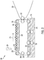
- FIG. 2 illustrates an example system 200 for incorporating non-evaporative drying in a commercial printing process in accordance with various embodiments.
- the membrane (e.g., transfer substrate) 204 is structured like a conventional intermediate transfer belt and moved so that it contacts a separate reservoir 226 of the draw solution 206 before coming into contact with a print substrate 220.
- Ink is jetted from an ejector 224 as droplet 202 onto a first surface 228 of the membrane 204.
- the membrane 204 is positioned proximate the draw solution reservoir 226 so that solvents (e.g., water) in the droplet 202 begin to transport across the membrane 204 to the draw solution 206.
- solvents e.g., water
- the membrane 204 is circulated by a plurality of rollers 212, as indicated by arrow 210, which keeps transported solvents from accumulating on the second surface 230 of the membrane 204.
- a print substrate e.g., paper
- the print substrate 220 may be circulated via rollers 222. After the ink is transferred to the print substrate 220, the membrane continues circulating through a cleaning tank 216.
- the cleaning tank includes solvent 218 for cleaning residual ink from the transfer substrate 204 before that portion of the transfer substrate returns to the ejector to receive subsequent droplets.
- the cleaning process can be enhanced through contact with the transfer substrate such as by wiping means or rollers 232 submerged within the cleaning solvent 218, in addition to similar cleaning elements to remove excess cleaning solvent after emerging from tank 216.
- the draw solution is further agitated by a second plurality of rollers 214 positioned within the draw solution reservoir 226.
- the second plurality of rollers 214 contact the draw solution 206 and bring a portion of the draw solution 206 in contact with the second surface 230 of the membrane 204, while also removing transported solvents from the immediate vicinity of the second surface 230 of the membrane 204. Agitation also serves to control concentration gradients within the draw solution.
- the draw solution 206 can be pumped in such a way that it comes in contact with, and flows relative to, the second surface 230 of the membrane 204.
- the flow distribution of draw solution 206 can be controlled by appropriate channels or fins, in order to reduce or minimize spatial variations in the removal of transported water away from the second surface 230 of the membrane 204.
- FIG. 3 illustrates an alternative embodiment for implementing non-evaporative drying in a printing process.
- the forward osmosis membrane 304 is wrapped around a tube 305 through which the draw solution 306 is circulated.
- Tube 305 has a plurality of openings 308, such as perforations, pores, or any sort of void space arising from the structure of tube 305.
- Tube 305 may be made of materials capable of providing structural support such as metal, plastic, or a woven surface so long as there are a plurality of openings for the draw solution to contact a surface of the transfer substrate.
- the draw solution 306 is contained in a reservoir within the tube, or the tube 305 serves as the reservoir.
- An ejector 324 jets ink droplets 302 onto an external surface of the membrane 304.
- the solvent transport then proceeds as described above through osmosis.
- the draw solution 306 is flowed through the tube thereby removing solvents from the ink droplets 302 away from the back, internal side of the membrane 304, through the openings 308.
- the tube 305 is rotated in conjunction with the membrane 304 (e.g., via an axle through an open center portion of the tube 310, or through frictional contact with a different roller), as indicated by arrow 312, thereby moving the droplet 302 away from the ejector 324 and towards eventual transfer to a print substrate.
- the rotation serves to agitate the draw solution 306 within the tube; however, additional agitating elements may be included within the draw solution reservoir. Agitation also serves to control concentration gradients within the draw solution. For example, in certain embodiments, a concentration gradient along the angular dimension of the tubular draw solution reservoir may be preferred over a concentration gradient in the lengthwise dimension.
- the draw solution is recycled or disposed of. If the draw solution is inexpensive (e.g., aqueous sodium chloride), and the components of the ink that are transported can be safely released to the environment, simple disposal of the draw solution may suffice. However, if the draw solution or transported ink components are expensive or hazardous, the draw solution can be regenerated, i.e., purified, e.g., through distillation. The distillation process is similar to thermal processes for water desalination. For example, ethanol is more volatile than many components in aqueous inks. If ethanol is used as a draw solution, it can easily be separated from the transported ink components, which themselves could be reused in a new batch of aqueous ink.
- the draw solution is inexpensive (e.g., aqueous sodium chloride)
- the draw solution or transported ink components are expensive or hazardous
- the draw solution can be regenerated, i.e., purified, e.g., through distillation.
- the distillation process is similar
- distillation could remove the comparatively more volatile draw solution solvent as well as water and solvents that have been absorbed from the ink, thereby reconcentrating the draw solution. Reusing the solvents absorbed from the ink could enable significant cost savings with respect to the cost of the ink.
- FIG. 4 illustrates a system 400 of non-evaporative solvent removal coupled with a separation system for the draw solution.
- a droplet 402 is provided on a first surface of a transfer substrate 404.
- Water and/or other solvents transport through the transfer substrate 404 via osmosis as indicated by arrow 408 to a second, opposing surface of the transfer substrate 404 and subsequently into the draw solution 406. This may be achieved in accordance with any of the embodiments described herein.
- the draw solution is directed out of the reservoir 418 as indicated by arrow 410.
- the draw solution including any ink components that have been transported through the transfer substrate 404, is provided to a separation system 412.
- Example separation processes include distillation and electrochemical separation procedures.
- the separation system 412 produces a purified draw solution stream 416 and at least one other stream 414 comprising the ink components (e.g., water and other solvents) that were transported across the transfer substrate and have been removed from the used draw solution.
- the ink components e.g., water and other solvents
- the stream 410 may include ethanol, water, glycerol, and other organic solvents originally present in the ink such as 2-pyrrolidinone.
- the purified stream 416 then comprises mostly ethanol and is recycled back to the draw solution reservoir 418.
- the recycling of the fluid can also support agitation of the draw solution 406 within the reservoir 418.
- the remaining at least one stream 414 may include the less volatile components of stream 410 such as water, glycerol, 2-pyrrolidinone, and other organic solvents. These components may be disposed, separated further, and/or recycled for further ink production.
- the stream 410 may include water, glycerol, and other organic solvents originally present in the ink such as 2-pyrrolidinone.
- the purified stream 416 then contains a lowered water content and the remaining at least one other stream 414 comprises mostly water.
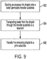
- Ink such as a droplet
- the droplet may include one or more solvents, including water, and at least one other component. Other components may include various solutes, latex, and pigments.
- the transfer substrate is a solvent permeable membrane
- the water and/or other organic solvents transfer from the first surface to a second, opposing surface (e.g., to a reservoir holding a draw solution) 904.
- the water and/or other solvents are transported naturally in response to osmotic pressure differentials, without application of outside forces.
- the partially dried ink droplet is subsequently transferred to a print substrate 906.
- the process may optionally include cleaning the transfer substrate prior to the transfer substrate receiving subsequent droplets and/or regeneration of the draw solution onsite or at another location.
- the net effect of the non-evaporative ink drying system is to remove solvents (such as water) from inkjet inks without having to work against their low volatility and high latent heat of vaporization.
- solvents such as water
- Incorporation of a non-evaporative ink drying system into a printer would allow for large energy savings while removing the need for complex thermal management that is otherwise necessary when using powerful thermal dryers. Any energy inputs would be limited to an optional regeneration of the draw solution, which itself could be separately located from the printer at a separate facility. Solvents removed from the ink could be reused to make more ink, which would lead to lower environmental impact and increased cost savings.
- an organic solvent that contains little water can also serve as a good draw solution for water transport, even when the donating fluid contains other solvents or solutes which would be expected to increase in concentration as more water is transported.
- the draw solution With absolute ethanol as the draw solution, a 10 ⁇ L water droplet is completely transported across the membrane in about three minutes.
- Composition A is a mixture of solvents that closely resembles a commercial aqueous pigmented ink (Collins PWK 1223), but which omits any pigment and dissolved latex to facilitate experimental observation.
- Composition B is a pigmented black ink (Impika A0011533 HD2) that contains carbon black as the pigment.
- Table 1A composition A
- Table 1B composition B
- Table 1A Water 63% Glycerol 12% 2-pyrrolidone 3% 1,2-hexanediol 3% 2-butoxyethanol 3% 1,3-propanediol 15% Surfynol 104H 1% Total 100%
- Table 1B Water 50-60% Glycerol 20-30% 2-pyrrolidone 1-10% Carbon black 1-10% Propylene glycol 4.99 Triethylene glycol monobutyl ether ⁇ 5 1,2-benzisothiazolin-3-one ⁇ 0.05 Total 100%
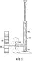
- FIG. 5 For quantitative analysis, a bench top test setup was constructed as shown in FIG. 5 .
- the ink composition sample (or water) 502 was placed in a first chamber 510 that is fluidly coupled to a second chamber (e.g., a graduated cylinder) 512 having graduations in increments of 0.01 mL (10 ⁇ L).
- the sample draw solution 506 is placed in the graduated cylinder 512.
- the forward osmosis membrane 504 is positioned between the first chamber 510 and second chamber 512 initially separating the sample ink composition (or water) 502 and draw solution 506 so that the sample ink composition is delivered directly to the front of the membrane 504 while the back of the membrane 504 remains in contact with the draw solution 506.
- a magnetic stir bar 508 is used to agitate the draw solution 506.
- the sample ink composition (or water) 502 is either agitated using a separate magnetic stir bar or is rapidly circulated using a peristaltic pump. Using this setup, the membrane flux is calculated from the change in volume of the draw solution over a certain period of time.
- Table 4 Draw Solution Ink Cosolvent Flux (L/m 2 h) Time to dry a 5 pL hemispherical droplet (sec) 50% Glycerol Impika HD2 A0011533 ⁇ 30% glycerol 1.31 24.4 Impika HF 008R13243 Unknown 2.24 14.3 Cabot Cab-o-jet 300 None 12.7 2.5 DyStar Jettex SDP Black None 12.7 2.5 40% LiCl Impika HF 008R13243 Unknown 5.95 5.4
- the transfer substrate i.e., membrane
- the transfer substrate used herein was cellulose triacetate (CTA). It is a material that has been optimized for water transport by being nonporous and surprisingly hydrophobic. This may be seen FIGS. 6 and 7 .
- FIG. 6 a cross section of a CTA membrane surface is shown indicating a smooth, pore-free surface at the bottom right 604 along with a supporting polymer matrix (the dark gray diagonal feature) 608.
- the hydrophobic nature is shown in FIG.
- a water droplet 702 has a contact angle of 65° on the CTA membrane surface.
- the contact angle was measured on a drop goniometer using the sessile drop technique.
- the measured contact angle is similar to that reported for nylon 6,6, and the nonporosity of the membrane, though not required in all embodiments, makes the membrane less likely to trap pigment particles.
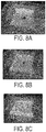
- FIGS. 8A-C show the membrane after the ink square is printed/jetted on the surface;
- FIG. 8B shows the same membrane after printing the square onto paper; and
- FIG. 8C shows the same membrane after being gently wiped with a damp paper towel. The cleaning removed all traces of pigment, and repetition of the procedure two subsequent times did not yield any apparent accumulation of pigment on the membrane surface.
- the membrane was observed to dry out and become more brittle after about five minutes if printing were to be done onto a membrane that had just been blotted dry.
- printing was done with a very small volume of water trapped between the membrane and an underlying plastic sheet substrate to keep the membrane hydrated indefinitely as long as liquid was present under it.
- the ink was also observed to form droplets instead of spreading evenly on the membrane surface. This may be due to the surface energy of the membrane being too low or the surface not being perfectly flat due to the woven polymer reinforcement under it.
- various embodiments directed to non-evaporative drying of ink can be implemented to improve printing processes.
- the process and system can remove volatile components such as water without evaporation or vapor condensation issues. Without the thermal components and management, non-evaporative separation consumes less energy, does not require thermal protection for other equipment, and the increased droplet drying speed enables small printing device sizes.
Landscapes
- Engineering & Computer Science (AREA)
- General Engineering & Computer Science (AREA)
- Ink Jet Recording Methods And Recording Media Thereof (AREA)
- Ink Jet (AREA)
- Inks, Pencil-Leads, Or Crayons (AREA)
Claims (17)
- Eine Vorrichtung, umfassend:ein lösungsmitteldurchlässiges Transfersubstrat (104) mit einer ersten Oberfläche (114) und einer der ersten Oberfläche gegenüberliegenden zweiten Oberfläche (116);einen Ejektor, ausgebildet, um ein Tröpfchen (102), umfassend mindestens Lösungsmittel, auf die erste Oberfläche des Transfersubstrats auszustoßen;ein Reservoir (226), umfassend eine Draw Solution (106) und ausgebildet, um die Draw Solution in Kontakt mit der zweiten Oberfläche des Transfersubstrats zu bringen; undein Drucksubstrat (220), ausgebildet, um einen Teil der ersten Oberfläche des Transfersubstrats zu berühren.
- Die Vorrichtung nach Anspruch 1, wobei das Reservoir ein Rührwerk enthält.
- Die Vorrichtung nach Anspruch 1, wobei das Transfersubstrat eine Endlosschleife umfasst und über eine Vielzahl von Rollen (212) zirkuliert wird.
- Die Vorrichtung nach Anspruch 3, ferner umfassend einen Reinigungstank (216), positioniert um das Transfersubstrat aufzunehmen, nachdem das Transfersubstrat das Drucksubstrat berührt.
- Die Vorrichtung nach Anspruch 1, wobei das Transfersubstrat ein durchgehendes Rohr umfasst und zu einem porösen Rohr mit kleinerem Durchmesser koaxial ist, wobei das Reservoir innerhalb des porösen Rohrs angeordnet ist.
- Die Vorrichtung nach Anspruch 1, wobei die Draw Solution relativ zum Tröpfchen einen höheren osmotischen Druck aufweist.
- Die Vorrichtung nach Anspruch 1, wobei das Transfersubstrat eine semipermeable Membran umfasst, die mindestens eine aus einer Vorwärtsosmosemembran, einer Umkehrosmosemembran, einer mikroporösen Membran und einer lonenaustauschmembran ist.
- Die Vorrichtung nach Anspruch 1, wobei das Tröpfchen wässrige Tinte umfasst.
- Die Vorrichtung nach Anspruch 1, wobei die Draw Solution mindestens eines umfasst aus einem anorganischen Salz, einem organischen Salz, einem organometallischen Salz, einer ionischen Flüssigkeit, einem Alkohol, einem Polyol, einem Kohlenhydrat und wässrigen oder nichtwässrigen Lösungen davon.
- Die Vorrichtung nach Anspruch 1,wobei der Ejektor ausgebildet ist, um ein Tröpfchen mit einem ersten osmotischen Druck und umfassend mindestens ein Lösungsmittel und mindestens eine andere Komponente, auf die erste Oberfläche des Transfersubstrats auszustoßen;wobei die Draw Solution einen zweiten osmotischen Druck aufweist, der höher ist als der erste osmotische Druck, das Reservoir ausgebildet ist, um die Draw Solution in Kontakt mit der zweiten Oberfläche des Transfersubstrats zu bringen;wobei die Vorrichtung ferner einen Separator umfasst, der mit dem Reservoir gekoppelt und ausgebildet ist, um die Draw Solution von dem mindestens einen Lösungsmittel zu trennen.
- Die Vorrichtung nach Anspruch 10, wobei der Separator ausgebildet ist, um das mindestens eine Lösungsmittel zu rezyklieren.
- Die Vorrichtung nach Anspruch 10, wobei der Separator eine regenerierte Draw Solution erzeugt und konfiguriert ist, um die regenerierte Draw Solution in das Reservoir zu rezyklieren.
- Die Vorrichtung nach Anspruch 10, wobei das Transfersubstrat eine Endlosschleife umfasst und über eine Vielzahl von Rollen zirkuliert wird.
- Ein Verfahren, umfassend:Aufbringen eines Tröpfchens, umfassend ein Lösungsmittel und mindestens eine andere Komponente, auf eine erste Oberfläche eines lösungsmitteldurchlässigen Transfersubstrats (902);Transportieren mindestens eines Teils des Lösungsmittels aus dem Tröpfchen durch das Transfersubstrat auf eine zweite Oberfläche des Transfersubstrats, wobei die zweite Oberfläche der ersten Oberfläche (904) gegenüberliegt; wobei die zweite Oberfläche ein Reservoir mit einer Draw Solution umfasst; undÜbertragen der mindestens einen anderen Komponente und des auf der ersten Oberfläche des Transfersubstrats verbleibenden Lösungsmittels auf ein Drucksubstrat (906).
- Das Verfahren nach Anspruch 14, wobei sich die zweite Oberfläche des Transfersubstrats in der Nähe einer Draw Solution befindet, die einen höheren osmotischen Druck als das Tröpfchen aufweist, und wobei der Anteil des Lösungsmittels durch Osmose transportiert wird.
- Das Verfahren nach Anspruch 15, ferner umfassend das Zirkulieren der Draw Solution weg von der zweiten Oberfläche des Transfersubstrats.
- Das Verfahren nach Anspruch 15, ferner umfassend das Zirkulieren des Transfersubstrats relativ zu der Draw Solution, während das Lösungsmittel durch das Transfersubstrat transportiert wird.
Applications Claiming Priority (1)
| Application Number | Priority Date | Filing Date | Title |
|---|---|---|---|
| US16/236,857 US10717271B1 (en) | 2018-12-31 | 2018-12-31 | Non-evaporative ink drying system and method |
Publications (2)
| Publication Number | Publication Date |
|---|---|
| EP3674094A1 EP3674094A1 (de) | 2020-07-01 |
| EP3674094B1 true EP3674094B1 (de) | 2021-09-01 |
Family
ID=69055794
Family Applications (1)
| Application Number | Title | Priority Date | Filing Date |
|---|---|---|---|
| EP19219927.1A Active EP3674094B1 (de) | 2018-12-31 | 2019-12-27 | Nichtverdampfendes wässriges tintentrocknungssystem und -verfahren |
Country Status (3)
| Country | Link |
|---|---|
| US (1) | US10717271B1 (de) |
| EP (1) | EP3674094B1 (de) |
| JP (1) | JP7324700B2 (de) |
Family Cites Families (11)
| Publication number | Priority date | Publication date | Assignee | Title |
|---|---|---|---|---|
| JP5051887B2 (ja) * | 2007-09-05 | 2012-10-17 | 富士フイルム株式会社 | 液体塗布装置及び方法並びに画像形成装置 |
| JP5407722B2 (ja) * | 2009-10-06 | 2014-02-05 | 株式会社リコー | クリーニング装置及び画像形成装置 |
| JP2013094963A (ja) * | 2011-10-27 | 2013-05-20 | Canon Inc | 画像形成方法および画像形成装置 |
| JP6328571B2 (ja) * | 2012-03-05 | 2018-05-23 | ランダ コーポレイション リミテッド | 剥離層の処理 |
| US8833896B2 (en) | 2012-05-02 | 2014-09-16 | Eastman Kodak Company | In-flight ink droplet drying method |
| JP2015024504A (ja) * | 2013-07-24 | 2015-02-05 | キヤノン株式会社 | 画像記録方法 |
| JP2016120625A (ja) * | 2014-12-24 | 2016-07-07 | 京セラドキュメントソリューションズ株式会社 | インクジェット記録装置 |
| US9789705B2 (en) * | 2015-04-24 | 2017-10-17 | Canon Kabushiki Kaisha | Ink jet recording method |
| EP3401100A4 (de) * | 2016-01-05 | 2019-08-21 | C/o Canon Kabushiki Kaisha | Tintenstrahlaufnahmevorrichtung und tintenstrahlaufnahmeverfahren |
| EP3401098A4 (de) * | 2016-01-05 | 2019-05-22 | C/o Canon Kabushiki Kaisha | Tintenstrahlaufzeichnungsvorrichtung und tintenstrahlaufzeichnungsverfahren |
| US20180354253A1 (en) * | 2017-06-09 | 2018-12-13 | The Procter & Gamble Company | Method for Applying Material onto and Conforming to Three-Dimensional Articles |
-
2018
- 2018-12-31 US US16/236,857 patent/US10717271B1/en active Active
-
2019
- 2019-12-11 JP JP2019223450A patent/JP7324700B2/ja active Active
- 2019-12-27 EP EP19219927.1A patent/EP3674094B1/de active Active
Also Published As
| Publication number | Publication date |
|---|---|
| US20200207074A1 (en) | 2020-07-02 |
| JP7324700B2 (ja) | 2023-08-10 |
| JP2020108956A (ja) | 2020-07-16 |
| EP3674094A1 (de) | 2020-07-01 |
| US10717271B1 (en) | 2020-07-21 |
Similar Documents
| Publication | Publication Date | Title |
|---|---|---|
| JP4003239B2 (ja) | インクジェット記録用インク組成物及びインクジェット記録方法 | |
| EP2988946B1 (de) | Druckverfahren | |
| ES2697345T3 (es) | Conjunto de tinta para impresión por chorro de tinta a base de aceite y procedimiento para producir artículo impreso | |
| US9302501B2 (en) | Printing apparatus | |
| CN103770464B (zh) | 印刷装置 | |
| JP2010241073A (ja) | 転写型インクジェット記録用中間転写体 | |
| CN105008468A (zh) | 油墨组合物 | |
| WO2017069077A1 (ja) | インクジェット画像形成方法 | |
| US20150367667A1 (en) | Processing fluid, image forming method, recorded matter, and inkjet recording device | |
| JP5987644B2 (ja) | 印刷装置 | |
| US10208221B2 (en) | Ink composition and ink jet recording method | |
| JP5600425B2 (ja) | インクジェット記録用水分散体の製造方法 | |
| EP3674094B1 (de) | Nichtverdampfendes wässriges tintentrocknungssystem und -verfahren | |
| EP2907671B1 (de) | Tintenstrahlaufzeichnungsverfahren | |
| US9539825B2 (en) | Printing device | |
| JPH06344654A (ja) | 印字記録物の作成方法、印字記録物の耐水性向上方法及びインクジェット記録方法 | |
| EP4570828A1 (de) | Wässrige zusammensetzung und drucksache | |
| US11738585B2 (en) | Method for applying an image onto the recording medium and corresponding printing apparatus | |
| JP5189718B2 (ja) | インクジェット用記録液の製造方法、インクジェット用記録液、これを用いたインクジェット記録方法及びインクジェット記録装置 | |
| EP3921174B1 (de) | Verfahren und vorrichtung zum digitalen drucken mit verbesserter flüssigkeitsbeseitigung | |
| JP3585108B2 (ja) | インクジェット記録方法およびそれに用いられるインク組成物 | |
| JP2024158955A (ja) | インクジェット印刷方法 | |
| JP2001234094A (ja) | インクジェット記録用インク、及びインクジェット記録方法 | |
| EP2964710B1 (de) | Tintenzusammensetzung | |
| JPH04357040A (ja) | インクジェット記録ヘッドの製造方法 |
Legal Events
| Date | Code | Title | Description |
|---|---|---|---|
| PUAI | Public reference made under article 153(3) epc to a published international application that has entered the european phase |
Free format text: ORIGINAL CODE: 0009012 |
|
| STAA | Information on the status of an ep patent application or granted ep patent |
Free format text: STATUS: THE APPLICATION HAS BEEN PUBLISHED |
|
| AK | Designated contracting states |
Kind code of ref document: A1 Designated state(s): AL AT BE BG CH CY CZ DE DK EE ES FI FR GB GR HR HU IE IS IT LI LT LU LV MC MK MT NL NO PL PT RO RS SE SI SK SM TR |
|
| AX | Request for extension of the european patent |
Extension state: BA ME |
|
| STAA | Information on the status of an ep patent application or granted ep patent |
Free format text: STATUS: REQUEST FOR EXAMINATION WAS MADE |
|
| 17P | Request for examination filed |
Effective date: 20210111 |
|
| RBV | Designated contracting states (corrected) |
Designated state(s): AL AT BE BG CH CY CZ DE DK EE ES FI FR GB GR HR HU IE IS IT LI LT LU LV MC MK MT NL NO PL PT RO RS SE SI SK SM TR |
|
| GRAP | Despatch of communication of intention to grant a patent |
Free format text: ORIGINAL CODE: EPIDOSNIGR1 |
|
| STAA | Information on the status of an ep patent application or granted ep patent |
Free format text: STATUS: GRANT OF PATENT IS INTENDED |
|
| RIC1 | Information provided on ipc code assigned before grant |
Ipc: B41M 5/03 20060101ALI20210315BHEP Ipc: B41M 5/025 20060101ALI20210315BHEP Ipc: B41J 29/377 20060101ALI20210315BHEP Ipc: B41M 7/00 20060101ALI20210315BHEP Ipc: B41J 29/17 20060101ALI20210315BHEP Ipc: B41J 11/00 20060101AFI20210315BHEP |
|
| INTG | Intention to grant announced |
Effective date: 20210401 |
|
| GRAS | Grant fee paid |
Free format text: ORIGINAL CODE: EPIDOSNIGR3 |
|
| GRAA | (expected) grant |
Free format text: ORIGINAL CODE: 0009210 |
|
| STAA | Information on the status of an ep patent application or granted ep patent |
Free format text: STATUS: THE PATENT HAS BEEN GRANTED |
|
| AK | Designated contracting states |
Kind code of ref document: B1 Designated state(s): AL AT BE BG CH CY CZ DE DK EE ES FI FR GB GR HR HU IE IS IT LI LT LU LV MC MK MT NL NO PL PT RO RS SE SI SK SM TR |
|
| REG | Reference to a national code |
Ref country code: GB Ref legal event code: FG4D |
|
| REG | Reference to a national code |
Ref country code: CH Ref legal event code: EP Ref country code: AT Ref legal event code: REF Ref document number: 1425828 Country of ref document: AT Kind code of ref document: T Effective date: 20210915 |
|
| REG | Reference to a national code |
Ref country code: DE Ref legal event code: R096 Ref document number: 602019007374 Country of ref document: DE |
|
| REG | Reference to a national code |
Ref country code: IE Ref legal event code: FG4D |
|
| REG | Reference to a national code |
Ref country code: LT Ref legal event code: MG9D |
|
| PG25 | Lapsed in a contracting state [announced via postgrant information from national office to epo] |
Ref country code: SE Free format text: LAPSE BECAUSE OF FAILURE TO SUBMIT A TRANSLATION OF THE DESCRIPTION OR TO PAY THE FEE WITHIN THE PRESCRIBED TIME-LIMIT Effective date: 20210901 Ref country code: RS Free format text: LAPSE BECAUSE OF FAILURE TO SUBMIT A TRANSLATION OF THE DESCRIPTION OR TO PAY THE FEE WITHIN THE PRESCRIBED TIME-LIMIT Effective date: 20210901 Ref country code: ES Free format text: LAPSE BECAUSE OF FAILURE TO SUBMIT A TRANSLATION OF THE DESCRIPTION OR TO PAY THE FEE WITHIN THE PRESCRIBED TIME-LIMIT Effective date: 20210901 Ref country code: BG Free format text: LAPSE BECAUSE OF FAILURE TO SUBMIT A TRANSLATION OF THE DESCRIPTION OR TO PAY THE FEE WITHIN THE PRESCRIBED TIME-LIMIT Effective date: 20211201 Ref country code: LT Free format text: LAPSE BECAUSE OF FAILURE TO SUBMIT A TRANSLATION OF THE DESCRIPTION OR TO PAY THE FEE WITHIN THE PRESCRIBED TIME-LIMIT Effective date: 20210901 Ref country code: HR Free format text: LAPSE BECAUSE OF FAILURE TO SUBMIT A TRANSLATION OF THE DESCRIPTION OR TO PAY THE FEE WITHIN THE PRESCRIBED TIME-LIMIT Effective date: 20210901 Ref country code: FI Free format text: LAPSE BECAUSE OF FAILURE TO SUBMIT A TRANSLATION OF THE DESCRIPTION OR TO PAY THE FEE WITHIN THE PRESCRIBED TIME-LIMIT Effective date: 20210901 Ref country code: NO Free format text: LAPSE BECAUSE OF FAILURE TO SUBMIT A TRANSLATION OF THE DESCRIPTION OR TO PAY THE FEE WITHIN THE PRESCRIBED TIME-LIMIT Effective date: 20211201 |
|
| REG | Reference to a national code |
Ref country code: AT Ref legal event code: MK05 Ref document number: 1425828 Country of ref document: AT Kind code of ref document: T Effective date: 20210901 |
|
| PG25 | Lapsed in a contracting state [announced via postgrant information from national office to epo] |
Ref country code: PL Free format text: LAPSE BECAUSE OF FAILURE TO SUBMIT A TRANSLATION OF THE DESCRIPTION OR TO PAY THE FEE WITHIN THE PRESCRIBED TIME-LIMIT Effective date: 20210901 Ref country code: LV Free format text: LAPSE BECAUSE OF FAILURE TO SUBMIT A TRANSLATION OF THE DESCRIPTION OR TO PAY THE FEE WITHIN THE PRESCRIBED TIME-LIMIT Effective date: 20210901 Ref country code: GR Free format text: LAPSE BECAUSE OF FAILURE TO SUBMIT A TRANSLATION OF THE DESCRIPTION OR TO PAY THE FEE WITHIN THE PRESCRIBED TIME-LIMIT Effective date: 20211202 |
|
| PG25 | Lapsed in a contracting state [announced via postgrant information from national office to epo] |
Ref country code: AT Free format text: LAPSE BECAUSE OF FAILURE TO SUBMIT A TRANSLATION OF THE DESCRIPTION OR TO PAY THE FEE WITHIN THE PRESCRIBED TIME-LIMIT Effective date: 20210901 |
|
| PG25 | Lapsed in a contracting state [announced via postgrant information from national office to epo] |
Ref country code: IS Free format text: LAPSE BECAUSE OF FAILURE TO SUBMIT A TRANSLATION OF THE DESCRIPTION OR TO PAY THE FEE WITHIN THE PRESCRIBED TIME-LIMIT Effective date: 20220101 Ref country code: SM Free format text: LAPSE BECAUSE OF FAILURE TO SUBMIT A TRANSLATION OF THE DESCRIPTION OR TO PAY THE FEE WITHIN THE PRESCRIBED TIME-LIMIT Effective date: 20210901 Ref country code: SK Free format text: LAPSE BECAUSE OF FAILURE TO SUBMIT A TRANSLATION OF THE DESCRIPTION OR TO PAY THE FEE WITHIN THE PRESCRIBED TIME-LIMIT Effective date: 20210901 Ref country code: RO Free format text: LAPSE BECAUSE OF FAILURE TO SUBMIT A TRANSLATION OF THE DESCRIPTION OR TO PAY THE FEE WITHIN THE PRESCRIBED TIME-LIMIT Effective date: 20210901 Ref country code: PT Free format text: LAPSE BECAUSE OF FAILURE TO SUBMIT A TRANSLATION OF THE DESCRIPTION OR TO PAY THE FEE WITHIN THE PRESCRIBED TIME-LIMIT Effective date: 20220103 Ref country code: NL Free format text: LAPSE BECAUSE OF FAILURE TO SUBMIT A TRANSLATION OF THE DESCRIPTION OR TO PAY THE FEE WITHIN THE PRESCRIBED TIME-LIMIT Effective date: 20210901 Ref country code: EE Free format text: LAPSE BECAUSE OF FAILURE TO SUBMIT A TRANSLATION OF THE DESCRIPTION OR TO PAY THE FEE WITHIN THE PRESCRIBED TIME-LIMIT Effective date: 20210901 Ref country code: CZ Free format text: LAPSE BECAUSE OF FAILURE TO SUBMIT A TRANSLATION OF THE DESCRIPTION OR TO PAY THE FEE WITHIN THE PRESCRIBED TIME-LIMIT Effective date: 20210901 Ref country code: AL Free format text: LAPSE BECAUSE OF FAILURE TO SUBMIT A TRANSLATION OF THE DESCRIPTION OR TO PAY THE FEE WITHIN THE PRESCRIBED TIME-LIMIT Effective date: 20210901 |
|
| REG | Reference to a national code |
Ref country code: DE Ref legal event code: R097 Ref document number: 602019007374 Country of ref document: DE |
|
| PLBE | No opposition filed within time limit |
Free format text: ORIGINAL CODE: 0009261 |
|
| STAA | Information on the status of an ep patent application or granted ep patent |
Free format text: STATUS: NO OPPOSITION FILED WITHIN TIME LIMIT |
|
| PG25 | Lapsed in a contracting state [announced via postgrant information from national office to epo] |
Ref country code: MC Free format text: LAPSE BECAUSE OF FAILURE TO SUBMIT A TRANSLATION OF THE DESCRIPTION OR TO PAY THE FEE WITHIN THE PRESCRIBED TIME-LIMIT Effective date: 20210901 Ref country code: IT Free format text: LAPSE BECAUSE OF FAILURE TO SUBMIT A TRANSLATION OF THE DESCRIPTION OR TO PAY THE FEE WITHIN THE PRESCRIBED TIME-LIMIT Effective date: 20210901 Ref country code: DK Free format text: LAPSE BECAUSE OF FAILURE TO SUBMIT A TRANSLATION OF THE DESCRIPTION OR TO PAY THE FEE WITHIN THE PRESCRIBED TIME-LIMIT Effective date: 20210901 |
|
| 26N | No opposition filed |
Effective date: 20220602 |
|
| PG25 | Lapsed in a contracting state [announced via postgrant information from national office to epo] |
Ref country code: SI Free format text: LAPSE BECAUSE OF FAILURE TO SUBMIT A TRANSLATION OF THE DESCRIPTION OR TO PAY THE FEE WITHIN THE PRESCRIBED TIME-LIMIT Effective date: 20210901 |
|
| REG | Reference to a national code |
Ref country code: BE Ref legal event code: MM Effective date: 20211231 |
|
| PG25 | Lapsed in a contracting state [announced via postgrant information from national office to epo] |
Ref country code: LU Free format text: LAPSE BECAUSE OF NON-PAYMENT OF DUE FEES Effective date: 20211227 Ref country code: IE Free format text: LAPSE BECAUSE OF NON-PAYMENT OF DUE FEES Effective date: 20211227 |
|
| PG25 | Lapsed in a contracting state [announced via postgrant information from national office to epo] |
Ref country code: BE Free format text: LAPSE BECAUSE OF NON-PAYMENT OF DUE FEES Effective date: 20211231 |
|
| PG25 | Lapsed in a contracting state [announced via postgrant information from national office to epo] |
Ref country code: CY Free format text: LAPSE BECAUSE OF FAILURE TO SUBMIT A TRANSLATION OF THE DESCRIPTION OR TO PAY THE FEE WITHIN THE PRESCRIBED TIME-LIMIT Effective date: 20210901 |
|
| PG25 | Lapsed in a contracting state [announced via postgrant information from national office to epo] |
Ref country code: HU Free format text: LAPSE BECAUSE OF FAILURE TO SUBMIT A TRANSLATION OF THE DESCRIPTION OR TO PAY THE FEE WITHIN THE PRESCRIBED TIME-LIMIT; INVALID AB INITIO Effective date: 20191227 |
|
| REG | Reference to a national code |
Ref country code: CH Ref legal event code: PL |
|
| PG25 | Lapsed in a contracting state [announced via postgrant information from national office to epo] |
Ref country code: LI Free format text: LAPSE BECAUSE OF NON-PAYMENT OF DUE FEES Effective date: 20221231 Ref country code: CH Free format text: LAPSE BECAUSE OF NON-PAYMENT OF DUE FEES Effective date: 20221231 |
|
| PG25 | Lapsed in a contracting state [announced via postgrant information from national office to epo] |
Ref country code: MK Free format text: LAPSE BECAUSE OF FAILURE TO SUBMIT A TRANSLATION OF THE DESCRIPTION OR TO PAY THE FEE WITHIN THE PRESCRIBED TIME-LIMIT Effective date: 20210901 |
|
| PG25 | Lapsed in a contracting state [announced via postgrant information from national office to epo] |
Ref country code: TR Free format text: LAPSE BECAUSE OF FAILURE TO SUBMIT A TRANSLATION OF THE DESCRIPTION OR TO PAY THE FEE WITHIN THE PRESCRIBED TIME-LIMIT Effective date: 20210901 |
|
| PG25 | Lapsed in a contracting state [announced via postgrant information from national office to epo] |
Ref country code: MT Free format text: LAPSE BECAUSE OF FAILURE TO SUBMIT A TRANSLATION OF THE DESCRIPTION OR TO PAY THE FEE WITHIN THE PRESCRIBED TIME-LIMIT Effective date: 20210901 |
|
| PGFP | Annual fee paid to national office [announced via postgrant information from national office to epo] |
Ref country code: DE Payment date: 20251126 Year of fee payment: 7 |
|
| PGFP | Annual fee paid to national office [announced via postgrant information from national office to epo] |
Ref country code: GB Payment date: 20251120 Year of fee payment: 7 |
|
| PGFP | Annual fee paid to national office [announced via postgrant information from national office to epo] |
Ref country code: FR Payment date: 20251120 Year of fee payment: 7 |