EP3673933A1 - Wegwerfbare doppelt wirkende kolbenpumpenanordnung - Google Patents
Wegwerfbare doppelt wirkende kolbenpumpenanordnung Download PDFInfo
- Publication number
- EP3673933A1 EP3673933A1 EP19220191.1A EP19220191A EP3673933A1 EP 3673933 A1 EP3673933 A1 EP 3673933A1 EP 19220191 A EP19220191 A EP 19220191A EP 3673933 A1 EP3673933 A1 EP 3673933A1
- Authority
- EP
- European Patent Office
- Prior art keywords
- piston
- fluid
- pump
- pulsation
- pump part
- Prior art date
- Legal status (The legal status is an assumption and is not a legal conclusion. Google has not performed a legal analysis and makes no representation as to the accuracy of the status listed.)
- Granted
Links
Images

Classifications
-
- F—MECHANICAL ENGINEERING; LIGHTING; HEATING; WEAPONS; BLASTING
- F04—POSITIVE - DISPLACEMENT MACHINES FOR LIQUIDS; PUMPS FOR LIQUIDS OR ELASTIC FLUIDS
- F04B—POSITIVE-DISPLACEMENT MACHINES FOR LIQUIDS; PUMPS
- F04B11/00—Equalisation of pulses, e.g. by use of air vessels; Counteracting cavitation
-
- F—MECHANICAL ENGINEERING; LIGHTING; HEATING; WEAPONS; BLASTING
- F04—POSITIVE - DISPLACEMENT MACHINES FOR LIQUIDS; PUMPS FOR LIQUIDS OR ELASTIC FLUIDS
- F04B—POSITIVE-DISPLACEMENT MACHINES FOR LIQUIDS; PUMPS
- F04B5/00—Machines or pumps with differential-surface pistons
- F04B5/02—Machines or pumps with differential-surface pistons with double-acting pistons
-
- A—HUMAN NECESSITIES
- A61—MEDICAL OR VETERINARY SCIENCE; HYGIENE
- A61B—DIAGNOSIS; SURGERY; IDENTIFICATION
- A61B90/00—Instruments, implements or accessories specially adapted for surgery or diagnosis and not covered by any of the groups A61B1/00 - A61B50/00, e.g. for luxation treatment or for protecting wound edges
- A61B90/08—Accessories or related features not otherwise provided for
-
- A—HUMAN NECESSITIES
- A61—MEDICAL OR VETERINARY SCIENCE; HYGIENE
- A61M—DEVICES FOR INTRODUCING MEDIA INTO, OR ONTO, THE BODY; DEVICES FOR TRANSDUCING BODY MEDIA OR FOR TAKING MEDIA FROM THE BODY; DEVICES FOR PRODUCING OR ENDING SLEEP OR STUPOR
- A61M5/00—Devices for bringing media into the body in a subcutaneous, intra-vascular or intramuscular way; Accessories therefor, e.g. filling or cleaning devices, arm-rests
- A61M5/14—Infusion devices, e.g. infusing by gravity; Blood infusion; Accessories therefor
- A61M5/142—Pressure infusion, e.g. using pumps
- A61M5/14212—Pumping with an aspiration and an expulsion action
- A61M5/14216—Reciprocating piston type
- A61M5/1422—Reciprocating piston type with double acting or multiple pistons
-
- F—MECHANICAL ENGINEERING; LIGHTING; HEATING; WEAPONS; BLASTING
- F04—POSITIVE - DISPLACEMENT MACHINES FOR LIQUIDS; PUMPS FOR LIQUIDS OR ELASTIC FLUIDS
- F04B—POSITIVE-DISPLACEMENT MACHINES FOR LIQUIDS; PUMPS
- F04B39/00—Component parts, details, or accessories, of pumps or pumping systems specially adapted for elastic fluids, not otherwise provided for in, or of interest apart from, groups F04B25/00 - F04B37/00
- F04B39/0027—Pulsation and noise damping means
- F04B39/0083—Pulsation and noise damping means using blow off silencers
-
- F—MECHANICAL ENGINEERING; LIGHTING; HEATING; WEAPONS; BLASTING
- F04—POSITIVE - DISPLACEMENT MACHINES FOR LIQUIDS; PUMPS FOR LIQUIDS OR ELASTIC FLUIDS
- F04B—POSITIVE-DISPLACEMENT MACHINES FOR LIQUIDS; PUMPS
- F04B53/00—Component parts, details or accessories not provided for in, or of interest apart from, groups F04B1/00 - F04B23/00 or F04B39/00 - F04B47/00
- F04B53/02—Packing the free space between cylinders and pistons
-
- F—MECHANICAL ENGINEERING; LIGHTING; HEATING; WEAPONS; BLASTING
- F04—POSITIVE - DISPLACEMENT MACHINES FOR LIQUIDS; PUMPS FOR LIQUIDS OR ELASTIC FLUIDS
- F04B—POSITIVE-DISPLACEMENT MACHINES FOR LIQUIDS; PUMPS
- F04B53/00—Component parts, details or accessories not provided for in, or of interest apart from, groups F04B1/00 - F04B23/00 or F04B39/00 - F04B47/00
- F04B53/14—Pistons, piston-rods or piston-rod connections
- F04B53/143—Sealing provided on the piston
-
- A—HUMAN NECESSITIES
- A61—MEDICAL OR VETERINARY SCIENCE; HYGIENE
- A61B—DIAGNOSIS; SURGERY; IDENTIFICATION
- A61B18/00—Surgical instruments, devices or methods for transferring non-mechanical forms of energy to or from the body
- A61B18/04—Surgical instruments, devices or methods for transferring non-mechanical forms of energy to or from the body by heating
- A61B18/12—Surgical instruments, devices or methods for transferring non-mechanical forms of energy to or from the body by heating by passing a current through the tissue to be heated, e.g. high-frequency current
- A61B18/14—Probes or electrodes therefor
- A61B18/1492—Probes or electrodes therefor having a flexible, catheter-like structure, e.g. for heart ablation
-
- A—HUMAN NECESSITIES
- A61—MEDICAL OR VETERINARY SCIENCE; HYGIENE
- A61B—DIAGNOSIS; SURGERY; IDENTIFICATION
- A61B18/00—Surgical instruments, devices or methods for transferring non-mechanical forms of energy to or from the body
- A61B2018/00005—Cooling or heating of the probe or tissue immediately surrounding the probe
- A61B2018/00011—Cooling or heating of the probe or tissue immediately surrounding the probe with fluids
-
- A—HUMAN NECESSITIES
- A61—MEDICAL OR VETERINARY SCIENCE; HYGIENE
- A61B—DIAGNOSIS; SURGERY; IDENTIFICATION
- A61B2218/00—Details of surgical instruments, devices or methods for transferring non-mechanical forms of energy to or from the body
- A61B2218/001—Details of surgical instruments, devices or methods for transferring non-mechanical forms of energy to or from the body having means for irrigation and/or aspiration of substances to and/or from the surgical site
- A61B2218/002—Irrigation
-
- A—HUMAN NECESSITIES
- A61—MEDICAL OR VETERINARY SCIENCE; HYGIENE
- A61M—DEVICES FOR INTRODUCING MEDIA INTO, OR ONTO, THE BODY; DEVICES FOR TRANSDUCING BODY MEDIA OR FOR TAKING MEDIA FROM THE BODY; DEVICES FOR PRODUCING OR ENDING SLEEP OR STUPOR
- A61M2205/00—General characteristics of the apparatus
- A61M2205/10—General characteristics of the apparatus with powered movement mechanisms
- A61M2205/103—General characteristics of the apparatus with powered movement mechanisms rotating
-
- A—HUMAN NECESSITIES
- A61—MEDICAL OR VETERINARY SCIENCE; HYGIENE
- A61M—DEVICES FOR INTRODUCING MEDIA INTO, OR ONTO, THE BODY; DEVICES FOR TRANSDUCING BODY MEDIA OR FOR TAKING MEDIA FROM THE BODY; DEVICES FOR PRODUCING OR ENDING SLEEP OR STUPOR
- A61M2205/00—General characteristics of the apparatus
- A61M2205/42—Reducing noise
-
- A—HUMAN NECESSITIES
- A61—MEDICAL OR VETERINARY SCIENCE; HYGIENE
- A61M—DEVICES FOR INTRODUCING MEDIA INTO, OR ONTO, THE BODY; DEVICES FOR TRANSDUCING BODY MEDIA OR FOR TAKING MEDIA FROM THE BODY; DEVICES FOR PRODUCING OR ENDING SLEEP OR STUPOR
- A61M5/00—Devices for bringing media into the body in a subcutaneous, intra-vascular or intramuscular way; Accessories therefor, e.g. filling or cleaning devices, arm-rests
- A61M5/007—Devices for bringing media into the body in a subcutaneous, intra-vascular or intramuscular way; Accessories therefor, e.g. filling or cleaning devices, arm-rests for contrast media
Definitions
- the present invention relates generally to medical pumps, and particularly to single-use medical pumps.
- U.S. Patent Application Publication 2008/0195058 describes apparatus and methods for engaging a pumping cartridge with a pump drive.
- the cartridge comprising a cylinder and a movable piston assembly, is initially assembled or subsequently positioned so that the distance between the attachment point on the piston assembly for coupling to a drive assembly, and a reference point on the cylinder, is greater than the maximal distance that will be encountered during normal oscillation of the piston during use.
- the cartridge in certain embodiments may be pressed into a drive assembly having means for immobilizing the cartridge and means for coupling the piston assembly to the driveshaft.
- the piston when the cartridge is fully inserted into the drive assembly, the piston is pressed into the cylinder sufficiently to establish a selected distance so that the piston shaft is in the proper position to engage with a coupling mechanism carried on the driveshaft.
- U.S. Patent Application Publication 2015/0327875 describes a system for aspirating thrombus that includes a catheter having an aspiration lumen configured to couple to a vacuum source.
- the system further has a disposable tubing set having a first conduit configured to couple the supply lumen of the aspiration catheter to a fluid source, and a pump component associated with the first conduit and configured to detachably couple to a drive unit.
- U.S. Patent Application Publication 2013/0123689 describes a breast pump apparatus comprising a vacuum pump and a variable-volume buffer volume coupled together in fluid communication.
- the apparatus also includes a breast-receiving portion coupled to the vacuum pump and the buffer volume such that the vacuum pump is operable to generate negative pressure at the breast-receiving portion to stimulate milk expression, and the negative pressure generated at the breast-receiving portion can be controlled by controlling the buffer volume.
- U.S. Patent Application Publication 2003/0220608 describes a method, system and apparatus for performing peritoneal dialysis.
- a method of controlling pressure in a medical fluid pump includes the steps of controlling a pump member acceleration during a first portion of a pump stroke and adaptively changing the pump member velocity during a second portion of the pump stroke.
- a blood pump of the system is configured to pump blood to a dialyzer of a hemodialysis apparatus, wherein the blood pump comprising a pneumatically actuated or controlled reciprocating diaphragm pump.
- the diaphragm of the pump comprises a flexible membrane formed or molded to generally conform to a curved inner wall of a pumping chamber or control chamber of the pump, wherein the diaphragm is preformed or molded to have a control side taking a convex shape, so that any elastic tension on the diaphragm is minimized when fully extended into a control chamber of the pump.
- U.S. Patent 5,921,951 describes an apparatus for pumping fluid at a steady rate.
- a first drive chamber having a movable outer surface, and a second drive chamber having a movable outer surface are provided.
- the apparatus further includes a block having a plurality of internal passages including a first passage for receiving the fluid into the block and a second passage for discharging the fluid from the block at the steady rate.
- the block has first and second internal chambers which are in fluid connection with the first and second passages.
- the first internal chamber has a first flexible surface for mating with the movable outer surface of the first drive chamber, and the second internal chamber has a second flexible surface for mating with the movable outer surface of the second drive chamber.
- At least one actuator is provided for applying positive pressure to the first flexible surface while simultaneously applying negative pressure to the second flexible surface and for applying negative pressure to the first flexible surface while simultaneously applying positive pressure to the second flexible surface.
- the actuator is respectively coupled to the first and second flexible surfaces by the first and second drive chambers.
- U.S. Patent 3,771,918 describes a multiple stage, linear, reciprocating, balanced-unopposed compressor that is driven by an analog of a turnbuckle with the drive having first and second pairs of associated recirculating ball bearing nuts and screws.
- the ball bearing nuts are constrained against axial displacement and are driven by a source of rotary power.
- the pairs of recirculating ball bearing nuts and screws are oppositely threaded and the screws are coupled together for reciprocation together.
- the screws are successively braked to produce reciprocation.
- the screw under power compresses gas in a plurality of stages in an isomer by driving a plurality of pistons.
- When the power stroke of a screw is completed, its brake is released and the other screw braked to compress gas in a second isomer identical with the first.
- the stroke of the compressor is variable for warmup purposes.
- U.S. Patent Application Publication 2014/0224829 describes a fluid pump device that is operable by a drive and actuating system.
- the fluid pump device includes a pump manifold, a plurality of pump cylinders, a plunger reciprocally operable in each of the pump cylinders, and at least one inlet selector valve.
- the inlet selector valve may be located laterally outboard of the pump cylinders and extend generally parallel to the pump cylinders.
- O-ring seals may be made of any type of suitable elastomeric material including polyurethane, silicone or EPDM rubbers, depending, for example, whether the sealed parts are static or are moving one with respect to the other.
- U.S. Patent Application Publication 2011/0144586 describes portable infusion devices, systems, and methods of using the same for dispensing materials.
- the devices, systems and methods may be used for infusing a material such as medicament, e.g., insulin, into a body in need thereof.
- the seals used may be made from materials such as butyl, silicone, polyurethanes or the like having a shore hardness of about 70A.
- U.S. Patent Application Publication 2011/0106003 describes a peritoneal dialysis system that includes a disposable cassette having an interface that includes at least one pump aperture.
- An at least one piston head moveable out of and retractable into the at least one pump aperture to move a corresponding pumping portion of a flexible sheet of the disposable cassette, the piston head moving within a vacuum chamber, the vacuum chamber enabling a vacuum to be pulled around the piston head to the flexible sheet of the disposable cassette.
- a shaft seal which can be of any known type, hereafter referred to as an O-ring, is also placed within a housing between a shaft opening and the piston to maintain the vacuum within the chamber.
- An embodiment of the present invention provides a pump device including a rotary motor, a compartment for insertion of a disposable pump part, and one or more pulsation-reduction elements.
- the disposable pump part includes an input port, an output port, and a dual-action reciprocating assembly.
- the input port is configured for intaking fluid.
- the output port is configured for outputting the fluid.
- the dual-action reciprocating assembly is configured for pumping the fluid.
- the assembly includes a single piston and a rod configured to be coupled to the rotary motor, so as to drive the piston.
- the one or more pulsation-reduction elements are configured to reduce a pulsation in the outputted fluid, caused by the single-piston dual-action reciprocating assembly.
- the one or more pulsation-reduction elements are configured to reduce variations in motion speed of the single piston.
- the one or more pulsation-reduction elements include a balloon damper which is fitted in the output port of the pump part.
- the one or more pulsation-reduction elements include a mechanical smoothing mechanism including a guide channel (e.g., a slit) and a bar that are configured to couple a shaft of the rotary motor to the rod.
- the bar is coupled to the shaft to move rotationally in the guide channel, and a profile of the guide channel is configured to speed-up and a slow-down a reciprocating motion of the rod by rotational motion the of the bar.
- the one or more pulsation-reduction elements include a processor that is configured to vary a rotation speed of the rotary motor.
- a disposable pump part for inserting into a compartment of a pump device, the disposable pump part including an input port, an output port, and a single-piston dual-action reciprocating assembly.
- the input port is configured for intaking fluid.
- the output port is configured for outputting the fluid.
- the dual-action reciprocating assembly is configured for pumping the fluid.
- the assembly includes a single piston, non-return valves, a rod, and a mechanical pulsation-reduction element.
- the non-return valves are configured to open and close interchangeably in response to the pumping by the single piston, so as to provide dual-action reciprocating pumping.
- the rod is configured to be coupled to a rotary motor of the pump device, so as to drive the single piston.
- the mechanical pulsation-reduction element is configured to reduce a pulsation in the outputted fluid, caused by the single-piston.
- the input port, the output port and the assembly are configured to be fitted in the pump device, and subsequently removed from the pump device at the end of use.
- a manufacturing method including assembling a single-use pump part including (a) an input port for intaking fluid, (b) an output port for outputting the fluid, and (c) a single-piston dual-action reciprocating assembly for pumping the fluid.
- the assembly includes (i) non-return valves, configured to open and close interchangeably in response to the pumping to provide dual-action reciprocating pumping, (ii) a rod configured to be coupled to a rotary motor, so as to drive the dual-action reciprocating assembly, and (iii) one or more pulsation-reduction elements that are configured to reduce a pulsation in the outputted fluid, caused by the single-piston dual-action reciprocating assembly.
- the assembled pump part is packaged in a sterile package.
- a manufacturing method including inserting a disposable single-piston dual-action reciprocating pump part into a compartment of a pump device.
- the pump part includes one or more pulsation-reduction elements that are configured to reduce a pulsation in fluid outputted from the pump part, caused by the single-piston dual-action reciprocating assembly.
- An input port of the pump part is connected to a fluid supply.
- An output port is connected to a fluid supply line of a medical device.
- the pump device is operated from a control panel of the pump device.
- Another embodiment of the present invention provides a disposable single-piston dual-action reciprocating pump part that includes a single piston, an output port, and a balloon damper.
- the output port is configured for outputting fluid pumped by the single piston.
- the balloon damper is fitted in the output port, and the balloon damper is configured to suppress a pulsation in a flow rate of the outputted fluid.
- the balloon damper is configured to accept a shape of a chamber into which the balloon is fitted.
- the balloon damper is configured to suppress the pulsation in the flow rate of the outputted fluid by the balloon damper returning, when the output flow rate is reduced, to an uncompressed volume and pushing extra fluid through the output port.
- a manufacturing method including partially assembling a disposable dual-action reciprocating pump part having an output port for outputting fluid.
- a balloon damper is fitted in the output port, and the balloon damper is configured to suppress a pulsation in a flow rate of the outputted fluid. the pump part assembly is then completed.
- the manufacturing method further includes packaging the assembled pump part in a sterile package.
- a disposable dual-action reciprocating pump part that includes an input port, an output port, a single-piston dual-action reciprocating assembly for pumping the fluid, and a mechanical smoothing mechanism.
- the input port is configured for intaking fluid.
- the output port is configured for outputting fluid pumped by the single piston.
- the single-piston dual-action reciprocating assembly for pumping the fluid includes a single piston, and a rod configured to be coupled to a shaft of a rotary motor.
- the mechanical smoothing mechanism includes a guide channel and a bar, which couples the shaft of the rotary motor to the rod such that a profile of the guide channel, in which the bar moves rotationally, is configured to speed-up and slow-down a reciprocating motion of the rod by rotational motion the of the bar.
- the pump part further includes non-return valves, configured to open and close interchangeably in response to pumping by the single piston, so as to provide dual-action reciprocating pumping.
- the pump part further includes a balloon damper, which is fitted in the output port, and the balloon damper is configured to suppress a pulsation in a flow rate at of the outputted fluid.
- the pump part further includes multiple silicone O-rings, which are configured to seal the piston against a cylinder of the pump part.
- a disposable dual-action reciprocating pump part that includes a piston and a cylinder, and multiple silicone O-rings.
- the piston is configured to move bi-directionally inside the cylinder.
- the multiple silicone O-rings are configured to seal the piston against the cylinder.
- At least one of the silicone-made O-rings is fixed relative to the piston and is configured to slide against the cylinder.
- a manufacturing method including partially assembling a disposable dual-action reciprocating pump part having a piston and a cylinder, and the piston is configured to move bi-directionally inside the cylinder. Multiple silicone made O-rings are fitted, which are configured to seal the piston against the cylinder. The assembly of the pump part in then completed.
- fitting multiple silicone made O-rings includes fitting at least one silicone made O-ring over the piston.
- a disposable medical pump is required to provide an output flow at a constant flow rate.
- such medical pump has to be a low-cost product. While some types of low-cost pumps, such as certain peristaltic pumps, may produce a steady flow, peristaltic pumps typically contain plastic components that are constantly flexed during pumping. The constant flexing of plastic parts generates electrical noise which may be picked up by some medical devices used in a medical procedure and degrade their performance.
- Embodiments of the present invention that are described hereinafter provide a disposable single-piston dual-action reciprocating pump part, free of flexing, which includes and/or is coupled to one or more pulsation-reduction elements that are configured to reduce pulsation in the output flow, caused by the reciprocating motion of the single piston of the pump part.
- pulsation is defined as a periodically recurring alternate increase and decrease of the output flow of the disclosed pump part, which is correlated with the reciprocating motion of the piston.
- a steady flow of fluid can thus be viewed as a complete lack of pulsation.
- the disclosed disposable pump part is configured to be easily fitted (i.e., inserted) in a compartment of a medical pump device (pump device also named hereinafter "pumping system").
- the pump part is configured for a "one-off" single use, and is subsequently readily removed from the pump device, e.g., at the end of use.
- the disposable pump part separates the part of the pump that is in contact with fluid from the pump driver.
- the entire disposable pump part does not require sterilization before use, and is mostly made of plastics.
- a pump device which comprise (a) a rotary motor, (b) a compartment for insertion of a disposable pump part, and (c) one or more pulsation-reduction elements included in the pump device.
- the disposable pump part comprises (i) an input port for intaking fluid, and an output port for outputting the fluid, (ii) a dual-action reciprocating assembly for pumping the fluid, wherein the assembly comprises a single piston and a rod configured to be coupled to the rotary motor, so as to drive the piston.
- Examples of pulsation-reduction elements include a damping balloon, a processor, a guide channel of a mechanical smoothing mechanism, the guide channel having a non-linear profile, which are all described below.
- the disclosed techniques are applicable to any other pulsation-reduction element that operates in conjunction with a single piston pump.
- the balloon damper which is fluid-coupled to the fluid flowing through the output port of the pump part, acts as a smoothing "capacitor" for the output flow.
- the disclosed balloon damper is fitted into a chamber inside the pump part. When the output flow is reduced the balloon returns to its original uncompressed volume and pushes extra fluid through the output port, thereby reducing the pulsation output to a minimum.
- the balloon regulates the output flow rate that is modulated by the piston motion by: (i) the balloon being compressed during the constant speed travel section of the piston, and (ii) at the end-points of piston travel, when output pressure falls, the balloon expands, increasing the flow rate from the lower value caused by the piston changing direction.
- the balloon damper is part of an output port of the pump part, all of which are disposable.
- the processor element controls the pump motor rotation speed, so that except for the end-points of its travel, the piston travels at a constant speed. At the piston travel end points, the processor varies the rotation speed of the motor to reduce the pulsation.
- the speeding up and slowing down of the piston is achieved in some embodiments mechanically, utilizing a mechanical smoothing mechanism that the pump device (i.e., pumping system) may comprise.
- the disclosed mechanical smoothing mechanism couples a rod that is part of the single-use pump part to a shaft of a rotary motor of the pumping device, to convert the rotation of the motor shaft into a periodic variable speed motion of the rod.
- the mechanical smoothing mechanism comprises a bar that is coupled to the shaft and is free to move in a guide channel having a non-linear profile. That way, the disclosed smoothing mechanism causes the piston of the pump part, which is fitted on the rod, to accelerate just before reaching travel end-points at which the piston halts.
- the disclosed piston motion act to compensate for the diminishing flow rate at the piston turning points.
- the design of the disclosed mechanical smoothing mechanism further takes into account attenuation of the flow rate along the output path, to provide variable speed piston motion that induces a uniform flow.
- Some embodiments of the present invention provide a disposable single-piston dual action reciprocating pump part comprising silicone made O-rings.
- the silicone made O-rings seal the piston against a cylinder, so as to enable pumping fluid as the piston moves bi-directionally inside the cylinder.
- at least one of the silicone-made O-rings is fixed relative to the piston and is configured to slide against the cylinder
- Silicone made O-rings typically exhibit poor tear resistance, abrasion and tensile strength.
- the poor abrasion resistance of a silicone made O-ring means that such O-ring is generally considered unsuitable for use as a seal with moving parts.
- the silicone made O-ring since the part is intended for "one-off" single use, the silicone made O-ring is also single-use and therefore the above drawbacks do not come into play.
- the velocity of the piston is kept low enough to ensure the silicone O-ring fulfills its task reliably in a "one-off" single use.
- Using low cost O-ring in a pump part intended for "one-off" single use may lower the cost of such pump part, and by so increase the adoption of disposable pumps in medical applications such as intravenous infusion of medications.
- the disclosed low-cost disposable single-piston dual-action pump with the disclosed techniques for the suppression of output flow pulsation may be used in medical procedures in which, for example, using a disposable peristaltic pump may introduce electrical disturbances.
- the disclosed single-use pump part can be used with an irrigated a radiofrequency cardiac ablation catheter, without adding electrical noises to low-amplitude electrophysiological signals sensed by other devices.
- the disclosed low-cost pump part may therefore increase the adoption of disposable pumps in medical procedures.
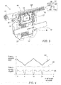
- Fig. 1 is a schematic volume rendering of a medical pump device 100 comprising a disposable single-piston dual-action pump part 10, in accordance with an embodiment of the present invention.
- the entire pump part (part 10) is configured to be easily fitted in device 100 for a single use and readily removed from device 100 at the end of use.
- Device 100 further comprises a rotary pump motor 30, which is connected to the pump via a connection mechanism (not marked in the figure) that converts the rotary action of the pump motor into a reciprocating motion of dual-action pump part 10.
- Dual-action pump part 10 has a fluid input port 14, to which a fluid supply is connected, and a fluid output port 16, which can be connected, for example, to a fluid supply line of a medical device, such as an irrigation port of a radiofrequency ablation catheter.
- Device 100 is a stand-alone device operated and monitored from a control panel 50.
- Inset 25 shows pump part 10 that is a single part configured to be fitted into device 100.
- the only interfaces of the part are the fluid input port 14, fluid output port 16, and a moving rod 12 which is coupled to move a piston inside pump part 10 to provide the pumping action.
- the disclosed single-use pump part 10 is connected to rotary pump motor 30 via a connecting rod and a screw mechanism.
- the screw mechanism converts the rotary action of the pump motor into a reciprocating motion of the connecting rod.
- pump part 10 may be different, so as to fit other designs of medical pump device 100.
- Fig. 2 is a schematic, pictorial illustration of the disposable single-piston dual-action pump part 10 of Fig. 1 , in accordance with an embodiment of the present invention.
- pumping part 10 is a one-part element that is configured to be fitted into device 100, with the only interfaces of the part being the fluid input port 14, fluid output port 16, and a moving rod 12 which is coupled to move a piston inside pump part 10 to provide the pumping action, as described below.
- rod 12 drives a piston 18 inside a cylinder 20, in a dual direction pumping action.
- Four non-return valves 22 open and close interchangeably (in pairs) to provide dual-action pumping.
- the reciprocating motion of piston 18, being usable at both opposing directions, causes fluid to be pumped from input port 14 into output port 16 in a largely continuous flow.
- pump part 10 is capable of pumping fluid largely continuously in a wide range of flow rates, from several ml/min to several tens of ml/min, and in a wide output pressure range, from sub PSI to several tens of PSI.
- Pump part 10 is mostly made of low-cost plastics parts, such as non-return valves 22, that allow the one-use model of the disclosed pump device.
- pump part 10 may be different, so as to fit other designs of device 100. Only elements relevant to the invention are described, whereas many other components included in pump part 10, such as O-rings, are not described for simplicity.
- Fig. 3 is a cross-sectional view of a disposable single-piston dual-action pump part 11 including a balloon damper 40, in accordance with an embodiment of the present invention.
- balloon 40 is fitted inside pump part 11 at the exit port of part 11.
- Pump part 11 functions as described for part 10 in Fig. 2 , with the only change between parts 10 and 11 being smoothing the output flow profile of part 10 using balloon damper 40.
- balloon 40 is configured to be compressed by surrounding fluid during the constant speed travel section of piston 18.
- the balloon expands, increasing the flow rate from the lower value caused by the piston changing direction.
- Inset 45 shows a graph that demonstrates the more uniform flowrate 55 when using balloon 40, as compared with a flowrate 53 profile demonstrated without using balloon 40. As seen by the shaded area, towards end points -X 0 and +X 0 , the output flow of the pump drops substantially unless balloon damper 40 is used.
- balloon 40 has a special half-crescent cylindrical shape, which best fit an available space inside part 11, so as to maximize the volume of the balloon and by so to maximize the damping effect of balloon 40 over pulsations in the output flow.
- Fig. 3 The example illustration shown in Fig. 3 is chosen purely for the sake of conceptual clarity.
- the shape of balloon 40 and the shape, location, and number of channels 44 may vary.
- Fig. 4 is a graph describing motion of the piston of the disposable dual-action pump of Fig. 1 as a function of an angle of the rotary motor of the pumping system, in accordance with an embodiment of the present invention.
- the disclosed graphs 52 and 55 are derived by a designer from a requirement for an outflow, seen as graph 60, being be as uniform as possible.
- Periodic graph 52 shows piston position as a function of shaft angle of the rotary driving motor. As seen, near turning points of piston travel (i.e., about rotary angles 0, ⁇ , 2 ⁇ ...), the piston position, X , depends non-linearly on the shaft angle. An underlying cause of the variable speed motion of the piston is seen in graph 55, in which the piston speed V X is increased just before and after piston speed decelerates as piston instantaneously halts at a cylinder turning end.
- a processor inside system 100 may instruct the system to vary the output flow rate, for example, by a combination of speeding up and slowing down the rotation of the motor, so as to reduce a pulsation.
- Fig. 5 is a schematic volume rendering of mechanical smoothing mechanism 40, in accordance with an embodiment of the present invention.
- mechanical smoothing mechanism 40 is used for achieving a desired profile of the output flow of part 10, such as profile 60.
- rod 12 is coupled to a guide hub 47 having a guide channel 48.
- a cylinder head 42 of mechanism 40 is coupled to a rotary shaft 41 of the driving motor (not seen).
- Guide hub 47 is coupled to head 42 by a bar 46 that is screwed into head 42 so that bar 46 rotates with rotary shaft 41. Because of guide channel 48, guide hub 47 is not rotationally coupled to rod 12, rather element 47 moves back and forth in a variable speed motion induced by bar 46 pushing and pulling element 47 (and with it rod 12 and hence piston 18) as bar 46 moves rotationally along guide channel 48, forcing guide hub 47 to translate rod 12 along its axis in accordance with the path defined by guide channel 48.
- Slit 48 profile is designed to convert the rotation of shaft 41 into the variable speed profile 55 V(X) of rod 12, seen in inset 45, as a function of the piston travel between turning ends -X 0 and +X 0 of the cylinder inside pump part 10.
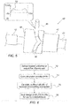
- Fig. 6 is a flow chart describing a design method of the mechanical smoothing mechanism 40 of Fig. 5 , in accordance with an embodiment of the present invention.
- the process begins with defining a required, constant as possible, output flow profile of pump part 10, at an output flow requirement step 70.
- a designer calculates piston velocity profile 55, at a piston velocity calculation step 72.
- the designer uses the velocity profile, calculates a profile of guide channel (e.g., slit) 48 of mechanical smoothing mechanism 40 that will produce the required the required output flow profile of pump part 10, at a mechanical guide channel profile calculation step 74.
- the designer saves the design of mechanical smoothing mechanism 40, including of slit 48, in a file for use by a manufacturer, at a design saving step 76.
- Fig. 7 is a cross-sectional view of the disposable single-piston dual-action pump part 10 of Fig. 1 including silicone O-rings 66, in accordance with an embodiment of the present invention. The functioning of part 10 is described in fig. 2 .
- Three silicone O-rings 40 are fitted in pump part 10 to seal piston 18 against cylinder 20, so as to establish efficient pumping functionality and to avoid leakages as piston 18 moves bi-directionally to pump the fluid, as described below.
- O-rings 66a and 66c are fitted in cylinder 20 in a way that O-rings 66a and 66c prevent fluid from leaking outside of pump part 10.
- O-ring 66b is fitted over piston 18 perimeter, so as to prevent pumped fluid (i.e., fluid under pressure) from leaking around piston 18 into the volume of cylinder 20 separated by piston 18, wherein that increased volume serves for fluid intaking. As the piston reverses direction, O-ring 66b serves to seal against flow in the opposite direction.
- Fig. 7 The example illustration shown in Fig. 7 is chosen purely for the sake of conceptual clarity.
- the cross-section, location and number of silicone O-rings 66 may vary.
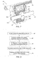
- Fig. 8 is a flow chart describing a manufacturing method of the disposable single-piston dual-action pump part 11 of Fig. 3 , in accordance with an embodiment of the present invention.
- the process begins with partially assembling disposable dual-action reciprocating pump part 11, at a pump part assembly step 80.
- silicone O-rings 66 are fitted into the partially assembled pump part 11, at a silicone O-rings fitting step 82.
- balloon damper 40 is fitted into the partially assembled pump part 11, at a balloon damper fitting step 84.
- the pulsation is controlled by the disclosed mechanical smoothing mechanism and/or by the processor changing the rate of rotation, as described above.
- the manufacturing method includes finishing the assembly of pump part 11 into the disposable dual-action reciprocating pump, at a pump full assembly step 86. Finally, the fully assembled pump part 10 is packaged in a sterile package, at a sterile packaging step 88.
- the embodiments described herein mainly address a non-sterilizable pump part for catheter irrigation
- the disclosed single-use pump part described herein can also be used in other medical applications, such as in injection of contrast agents for medical imaging and in intravenous infusion.
Landscapes
- Engineering & Computer Science (AREA)
- Health & Medical Sciences (AREA)
- Life Sciences & Earth Sciences (AREA)
- General Engineering & Computer Science (AREA)
- Mechanical Engineering (AREA)
- Veterinary Medicine (AREA)
- Biomedical Technology (AREA)
- Heart & Thoracic Surgery (AREA)
- Animal Behavior & Ethology (AREA)
- General Health & Medical Sciences (AREA)
- Public Health (AREA)
- Anesthesiology (AREA)
- Hematology (AREA)
- Vascular Medicine (AREA)
- Surgery (AREA)
- Nuclear Medicine, Radiotherapy & Molecular Imaging (AREA)
- Medical Informatics (AREA)
- Molecular Biology (AREA)
- Pathology (AREA)
- Oral & Maxillofacial Surgery (AREA)
- Cardiology (AREA)
- Physics & Mathematics (AREA)
- Plasma & Fusion (AREA)
- Otolaryngology (AREA)
- Infusion, Injection, And Reservoir Apparatuses (AREA)
- Reciprocating Pumps (AREA)
- Details Of Reciprocating Pumps (AREA)
- Control Of Positive-Displacement Pumps (AREA)
Applications Claiming Priority (5)
| Application Number | Priority Date | Filing Date | Title |
|---|---|---|---|
| US201862786407P | 2018-12-29 | 2018-12-29 | |
| US201862786406P | 2018-12-29 | 2018-12-29 | |
| US201862786404P | 2018-12-29 | 2018-12-29 | |
| US201862786402P | 2018-12-29 | 2018-12-29 | |
| US16/584,768 US11698059B2 (en) | 2018-12-29 | 2019-09-26 | Disposable dual-action reciprocating pump assembly |
Publications (3)
| Publication Number | Publication Date |
|---|---|
| EP3673933A1 true EP3673933A1 (de) | 2020-07-01 |
| EP3673933C0 EP3673933C0 (de) | 2025-10-15 |
| EP3673933B1 EP3673933B1 (de) | 2025-10-15 |
Family
ID=69055908
Family Applications (1)
| Application Number | Title | Priority Date | Filing Date |
|---|---|---|---|
| EP19220191.1A Active EP3673933B1 (de) | 2018-12-29 | 2019-12-31 | Wegwerfbare doppelt wirkende kolbenpumpenanordnung |
Country Status (5)
| Country | Link |
|---|---|
| US (2) | US11698059B2 (de) |
| EP (1) | EP3673933B1 (de) |
| JP (1) | JP2020109293A (de) |
| CN (1) | CN111379682B (de) |
| IL (1) | IL271629B2 (de) |
Families Citing this family (3)
| Publication number | Priority date | Publication date | Assignee | Title |
|---|---|---|---|---|
| US11698059B2 (en) * | 2018-12-29 | 2023-07-11 | Biosense Webster (Israel) Ltd. | Disposable dual-action reciprocating pump assembly |
| JP7409232B2 (ja) * | 2020-06-03 | 2024-01-09 | 住友電装株式会社 | 複合成形部品 |
| CN113750898B (zh) * | 2021-10-12 | 2024-10-29 | 山东华景机电设备有限公司 | 乳化液泵站 |
Citations (15)
| Publication number | Priority date | Publication date | Assignee | Title |
|---|---|---|---|---|
| US3771918A (en) | 1972-07-24 | 1973-11-13 | A Winter | Linear positive displacement pump with rotary to reciprocating drive |
| US3818934A (en) * | 1973-03-09 | 1974-06-25 | American Hospital Supply Corp | Dampening unit for pulsatile pump |
| US5921951A (en) | 1996-11-22 | 1999-07-13 | Therakos, Inc. | Apparatus for pumping fluid at a steady flow rate |
| US20030220608A1 (en) | 2002-05-24 | 2003-11-27 | Bruce Huitt | Method and apparatus for controlling medical fluid pressure |
| US20080195058A1 (en) | 2001-04-27 | 2008-08-14 | Hydrocision, Inc. | Methods and apparatuses for joining a pumping cartridge to a pump drive |
| US20110106003A1 (en) | 2002-07-19 | 2011-05-05 | Baxter International Inc. | Dialysis system and method for cassette-based pumping and valving |
| US20110144586A1 (en) | 2009-07-30 | 2011-06-16 | Tandem Diabetes Care, Inc. | Infusion pump system with disposable cartridge having pressure venting and pressure feedback |
| US20120053557A1 (en) * | 2010-08-26 | 2012-03-01 | Carefusion 303, Inc. | Iv pump dual piston disposable cassette and system |
| US20120244018A1 (en) * | 2011-03-25 | 2012-09-27 | Reilly David M | Pumping devices, systems including multiple pistons and methods for use with medical fluids |
| US20130123689A1 (en) | 2010-07-29 | 2013-05-16 | Koninklijke Philips Electronics N.V. | Piston pump with variable buffer |
| US20140161644A1 (en) * | 2012-05-25 | 2014-06-12 | Richard Weatherley | Diaphragm Pump |
| US20140224829A1 (en) | 2011-09-21 | 2014-08-14 | Bayer Medical Care Inc. | Continuous Multi-Fluid Delivery System and Method |
| US20150327875A1 (en) | 2014-05-19 | 2015-11-19 | Walk Vascular, Llc | Systems and methods for removal of blood and thrombotic material |
| US20170326282A1 (en) | 2006-04-14 | 2017-11-16 | Deka Products Limited Partnership | Blood treatment systems and methods |
| US9925331B2 (en) * | 2013-03-11 | 2018-03-27 | Boston Scientific Limited | Double action infusion system |
Family Cites Families (102)
| Publication number | Priority date | Publication date | Assignee | Title |
|---|---|---|---|---|
| US1290803A (en) | 1918-04-13 | 1919-01-07 | Burchard Thoens | Equalizing-valve. |
| US1625500A (en) | 1923-11-21 | 1927-04-19 | Quinn Martin Joseph | Pump |
| US1598137A (en) | 1925-12-16 | 1926-08-31 | Duriron Co | Double-acting-plunger pump |
| FR81610E (fr) | 1962-01-02 | 1963-10-18 | Pompe permettant de refouler des liquides abrasifs ou corrosifs et plus particulièrement adaptée à la pulvérisation de produits utilisés dans le traitement des cultures | |
| US3654964A (en) | 1969-03-03 | 1972-04-11 | Jean Mercier | Pressure vessels |
| US3838941A (en) | 1973-05-29 | 1974-10-01 | V Roschupkin | Pumping unit |
| US4065230A (en) | 1975-01-17 | 1977-12-27 | Hart Associates, Inc. | Reciprocating infusion pump and directional adapter set for use therewith |
| JPS5520687U (de) | 1978-07-28 | 1980-02-08 | ||
| US4575313A (en) | 1983-02-02 | 1986-03-11 | Halliburton Company | Digital pressure controller |
| US5066282A (en) | 1987-09-23 | 1991-11-19 | Leocor, Inc. | Positive displacement piston driven blood pump |
| US4976590A (en) | 1988-06-08 | 1990-12-11 | Baldwin Brian E | Fluid conduit-responsively adjustable pump arrangement and pump/conduit arrangement and method, and fluid conduits therefor |
| US5089017A (en) | 1989-01-17 | 1992-02-18 | Young David B | Drive system for artificial hearts and left-ventricular assist devices |
| US5092037A (en) | 1990-01-05 | 1992-03-03 | Dennis Pinkerton | Method of making a valveless positive displacement pump including a living hinge for angular adjustment |
| EP0713564B1 (de) | 1992-10-27 | 2001-09-26 | Glockemann Peck Engineering Pty. Ltd. | Hubkolbenmotor |
| US5322418A (en) | 1992-11-19 | 1994-06-21 | The Toro Company | High pressure liquid pump apparatus and pumping method |
| US5391199A (en) | 1993-07-20 | 1995-02-21 | Biosense, Inc. | Apparatus and method for treating cardiac arrhythmias |
| DE4327152C2 (de) | 1993-08-12 | 1995-10-19 | Stoeckert Instr Gmbh | Rollenpumpe |
| NZ250010A (en) | 1993-10-20 | 1995-06-27 | Richard John Newson | Expansible chamber liquid metering device with valved piston |
| US5450743A (en) | 1994-01-10 | 1995-09-19 | Zymark Corporation | Method for providing constant flow in liquid chromatography system |
| US5387088A (en) | 1994-01-18 | 1995-02-07 | Haemonetics Corporation | Peristaltic pump tube loading assembly |
| FR2719873A1 (fr) | 1994-05-11 | 1995-11-17 | Debiotech Sa | Dispositif de pompe péristaltique. |
| ES2144123T3 (es) | 1994-08-19 | 2000-06-01 | Biosense Inc | Sistemas medicos de diagnosis, de tratamiento y de imagen. |
| US6690963B2 (en) | 1995-01-24 | 2004-02-10 | Biosense, Inc. | System for determining the location and orientation of an invasive medical instrument |
| US7267666B1 (en) | 1995-04-20 | 2007-09-11 | Acist Medical Systems, Inc. | Angiographic injector system with multiple processor redundancy |
| FR2737261B1 (fr) | 1995-07-27 | 1997-10-10 | Jean Francois Ognier | Pompe peristaltique |
| JPH0942159A (ja) | 1995-08-02 | 1997-02-10 | Tonokura Ika Kogyo Kk | ロ−ラポンプ |
| CA2246287C (en) | 1996-02-15 | 2006-10-24 | Biosense, Inc. | Medical procedures and apparatus using intrabody probes |
| ES2210498T3 (es) | 1996-02-15 | 2004-07-01 | Biosense, Inc. | Transductores posicionables independientemente para sistema de localizacion. |
| CA2198544A1 (en) | 1996-03-21 | 1997-09-22 | Bayer Corporation | Apparatus for simultaneous aspiration and dispensation of fluids |
| JP3874484B2 (ja) * | 1997-03-05 | 2007-01-31 | スーガン株式会社 | 医療用インジェクタヘッド |
| US6162030A (en) * | 1997-06-13 | 2000-12-19 | Encynova International, Inc. | Zero leakage valveless positive fluid displacement device |
| EP1611911B1 (de) | 1997-11-07 | 2009-01-14 | ACIST Medical Systems, Inc. | Angiographie-Spritze mit mehrfachredundanten Prozessoren |
| US6135719A (en) | 1997-12-29 | 2000-10-24 | Oilquip, Inc. | Method and apparatus for metering injection pump flow |
| US6239724B1 (en) | 1997-12-30 | 2001-05-29 | Remon Medical Technologies, Ltd. | System and method for telemetrically providing intrabody spatial position |
| US7776014B2 (en) | 1998-01-29 | 2010-08-17 | Peter Visconti | Disposable surgical suction/irrigation trumpet valve tube cassette |
| US6484118B1 (en) | 2000-07-20 | 2002-11-19 | Biosense, Inc. | Electromagnetic position single axis system |
| DE20109803U1 (de) | 2001-06-12 | 2002-10-24 | Fresenius HemoCare GmbH, 61352 Bad Homburg | Pumpenbett für eine Rollenpumpe |
| WO2003007797A2 (en) | 2001-07-17 | 2003-01-30 | Kerberos Proximal Solutions | Fluid exchange system for controlled and localized irrigation and aspiration |
| US6913933B2 (en) | 2001-12-03 | 2005-07-05 | Ortho-Clinical Diagnostics, Inc. | Fluid dispensing algorithm for a variable speed pump driven metering system |
| US7729742B2 (en) | 2001-12-21 | 2010-06-01 | Biosense, Inc. | Wireless position sensor |
| US20040068178A1 (en) | 2002-09-17 | 2004-04-08 | Assaf Govari | High-gradient recursive locating system |
| JP4181429B2 (ja) * | 2003-03-04 | 2008-11-12 | 応研精工株式会社 | ピストンポンプ |
| WO2005007223A2 (en) | 2003-07-16 | 2005-01-27 | Sasha John | Programmable medical drug delivery systems and methods for delivery of multiple fluids and concentrations |
| EP1602826B1 (de) * | 2004-06-04 | 2007-06-27 | Société Industrielle de Sonceboz S.A. | Pumpenantrieb |
| JP4690034B2 (ja) | 2004-12-28 | 2011-06-01 | エスアイアイ・プリンテック株式会社 | チューブポンプ、インクジェット記録装置、及びインク供給方法 |
| DE102005009626A1 (de) | 2005-02-24 | 2006-08-31 | Universität Tübingen | Kamera zum Verfolgen von Objekten |
| US8282574B2 (en) | 2005-08-10 | 2012-10-09 | C. R. Bard, Inc. | Single-insertion, multiple sampling biopsy device usable with various transport systems and integrated markers |
| US7935077B2 (en) | 2005-09-28 | 2011-05-03 | Medrad, Inc. | Thrombectomy catheter deployment system |
| US7842010B2 (en) | 2005-12-05 | 2010-11-30 | Medrad, Inc. | Pneumatically-operated thrombectomy catheter deployment system |
| US20070258838A1 (en) | 2006-05-03 | 2007-11-08 | Sherwood Services Ag | Peristaltic cooling pump system |
| FI20060450A7 (fi) | 2006-05-09 | 2007-11-10 | Huhtasalo Jouko | Järjestelmä toimisylinterin asemoimiseksi, järjestelmän käyttö ja työkone |
| JP2008031862A (ja) * | 2006-07-26 | 2008-02-14 | Tokiko Techno Kk | ポンプユニット |
| ATE529147T1 (de) | 2006-08-23 | 2011-11-15 | Medtronic Minimed Inc | Systeme und verfahren zur füllung von behältern und zur ausgabe eines infusionsmediums |
| WO2008064174A1 (en) | 2006-11-17 | 2008-05-29 | National Quality Care, Inc. | Enhanced clearance in an artificial kidney incorporating a pulsatile pump |
| US8690870B2 (en) | 2006-12-28 | 2014-04-08 | St. Jude Medical, Atrial Fibrillation Division, Inc. | Irrigated ablation catheter system with pulsatile flow to prevent thrombus |
| JP4353333B2 (ja) | 2007-03-30 | 2009-10-28 | Smc株式会社 | 複動形エアシリンダの位置決め制御機構 |
| EP2152333B1 (de) * | 2007-05-07 | 2012-10-17 | Carmeli Adahan | Saugsystem |
| EP2262457B1 (de) | 2008-03-12 | 2011-09-28 | Carl Zeiss Surgical GmbH | Ophthalmochirurgisches system |
| IT1391274B1 (it) | 2008-08-08 | 2011-12-01 | Medica S R L Ab | Sistema di irrigazione ed aspirazione, in particolare per chirurgia laparoscopica |
| BRPI0901908A2 (pt) | 2009-03-17 | 2011-02-01 | Cruz Luis Eduardo Da | dispositivo para infusão controlada de formulações lìquidas em tecidos e órgãos em procedimentos de terapia celular |
| JP5399217B2 (ja) | 2009-11-24 | 2014-01-29 | 日機装株式会社 | 往復動ポンプ及びそれを具備した透析装置 |
| JP5506343B2 (ja) * | 2009-11-24 | 2014-05-28 | 日機装株式会社 | 往復動ポンプ及びそれを具備した透析装置 |
| US9480791B2 (en) | 2009-12-21 | 2016-11-01 | Bayer Healthcare Llc | Pumping devices, systems and methods for use with medical fluids including compensation for variations in pressure or flow rate |
| US8366667B2 (en) | 2010-02-11 | 2013-02-05 | Baxter International Inc. | Flow pulsatility dampening devices |
| DE102010020573A1 (de) * | 2010-05-14 | 2011-11-17 | Netstal-Maschinen Ag | Verfahren zum Betrieb eines Hybridantriebs und Hybridantrieb |
| US9676018B2 (en) | 2010-06-18 | 2017-06-13 | The University Of Queensland | Method and apparatus for forming the profile of deformable materials and deformable tubular sections |
| CA2805744A1 (en) | 2010-07-16 | 2012-01-19 | Medrad, Inc. | Peristaltic pump assemblies and systems incorporating such pump assemblies |
| ES2605804T3 (es) | 2010-08-20 | 2017-03-16 | Graco Minnesota Inc. | Procedimiento para sincronizar un sistema de bombas lineales |
| US8597239B2 (en) | 2011-03-01 | 2013-12-03 | Sanovas, Inc. | Abrading balloon catheter for extravasated drug delivery |
| US9353757B2 (en) * | 2011-03-03 | 2016-05-31 | Brian Carter Jones | Magnetically actuated fluid pump |
| US10743932B2 (en) | 2011-07-28 | 2020-08-18 | Biosense Webster (Israel) Ltd. | Integrated ablation system using catheter with multiple irrigation lumens |
| DE202011108638U1 (de) | 2011-12-02 | 2013-03-07 | Ulrich Gmbh & Co. Kg | Vorrichtung zum sterilen Transfer eines Mediums. |
| US9101269B2 (en) | 2011-12-15 | 2015-08-11 | Biosense Webster (Israel), Ltd. | Self-holding medical device control handle with cam actuated clutch mechanism |
| US9076065B1 (en) | 2012-01-26 | 2015-07-07 | Google Inc. | Detecting objects in images |
| JP5872966B2 (ja) | 2012-05-29 | 2016-03-01 | 日機装株式会社 | マルチチューブポンプ、定量サンプリング装置、および生体成分測定装置 |
| US9107986B2 (en) | 2013-03-11 | 2015-08-18 | Boston Scientific Limited | Double action infusion pump |
| US20140276379A1 (en) | 2013-03-15 | 2014-09-18 | Medrad, Inc. | Intelligent and configurable fluid delivery system and methods for its use |
| JP6066318B2 (ja) | 2013-06-06 | 2017-01-25 | 日本ライフライン株式会社 | 電極カテーテルシステム |
| WO2015016784A1 (en) | 2013-08-01 | 2015-02-05 | National University Of Singapore | A method and apparatus for tracking microblog messages for relevancy to an entity identifiable by an associated text and an image |
| PL2881128T3 (pl) | 2013-12-04 | 2019-04-30 | Hoffmann La Roche | Ambulatoryjny system infuzyjny zawierajęcy krokowy mechanizm przestawiania do sterowania zaworem |
| KR101510004B1 (ko) | 2013-12-10 | 2015-04-09 | 경북대학교 산학협력단 | 조영제 특성 분석을 위한 인체모델 장치 |
| DE102014102591A1 (de) * | 2014-02-27 | 2015-08-27 | Rausch & Pausch Gmbh | Verfahren zum Fördern von Hydraulikfluid und elektrohydraulische Motor-Pumpen-Einheit dafür |
| JP2015224606A (ja) | 2014-05-28 | 2015-12-14 | 株式会社エーエスエム | 搾り出し式ポンプの冷却構造 |
| DE102014112324A1 (de) | 2014-08-27 | 2016-03-03 | Stockert Gmbh | Schlauchpumpe |
| EP3185928A2 (de) | 2014-08-28 | 2017-07-05 | Boston Scientific Limited | Doppeltwirkendes infusionssystem |
| US9965704B2 (en) | 2014-10-31 | 2018-05-08 | Paypal, Inc. | Discovering visual concepts from weakly labeled image collections |
| US10245373B2 (en) * | 2014-12-01 | 2019-04-02 | Carefusion 2200, Inc. | Pump cassettes with positioning feature and infusion pump systems |
| DE102015106612A1 (de) | 2015-04-29 | 2016-11-03 | Ebm-Papst St. Georgen Gmbh & Co. Kg | Pumpenvorrichtung |
| JP6562296B2 (ja) * | 2015-06-25 | 2019-08-21 | 株式会社郷田製作所 | ピストンの往復運動機構、ポンプ、コンプレッサー、及び真空ポンプ |
| EP3347067A1 (de) * | 2015-09-10 | 2018-07-18 | Excitus AS | Anordnungen und verfahren zur vermeidung der ausbreitung von infektionserregern und zur verbesserung der elektrischen sicherheit und saugleistung einer medizinischen saugvorrichtung |
| US10576207B2 (en) | 2015-10-09 | 2020-03-03 | West Pharma. Services IL, Ltd. | Angled syringe patch injector |
| WO2017051804A1 (ja) | 2015-09-25 | 2017-03-30 | テルモ株式会社 | 薬液投与装置 |
| FR3044052B1 (fr) * | 2015-11-25 | 2019-09-13 | Exel Industries | Pompe d'alimentation d'un systeme d'application d'un produit de revetement liquide |
| US10145760B2 (en) | 2016-01-05 | 2018-12-04 | Biosense Webster (Israel) Ltd. | Status of an irrigation pump |
| US20180014878A1 (en) | 2016-07-13 | 2018-01-18 | Biosense Webster (Israel) Ltd. | Diaphragm pumps for medical applications |
| US10907626B2 (en) | 2017-02-16 | 2021-02-02 | Biosense Webster (Israel) Ltd. | Peristaltic pump with reduced triboelectric effects |
| US10918832B2 (en) | 2017-03-27 | 2021-02-16 | Biosense Webster (Israel) Ltd | Catheter with improved loop contraction and greater contraction displacement |
| US10973739B2 (en) | 2018-08-23 | 2021-04-13 | ART MEDICAL Ltd. | Medical pump |
| FR3085761B1 (fr) | 2018-09-11 | 2021-01-15 | Continental Automotive France | Systeme et procede de localisation de la position d'un objet routier par apprentissage automatique non supervise |
| US11200454B1 (en) | 2018-10-17 | 2021-12-14 | Objectvideo Labs, Llc | People selection for training set |
| US11295026B2 (en) | 2018-11-20 | 2022-04-05 | Forcepoint, LLC | Scan, detect, and alert when a user takes a photo of a computer monitor with a mobile phone |
| US11698059B2 (en) * | 2018-12-29 | 2023-07-11 | Biosense Webster (Israel) Ltd. | Disposable dual-action reciprocating pump assembly |
-
2019
- 2019-09-26 US US16/584,768 patent/US11698059B2/en active Active
- 2019-12-22 IL IL271629A patent/IL271629B2/en unknown
- 2019-12-27 CN CN201911377781.5A patent/CN111379682B/zh active Active
- 2019-12-27 JP JP2019237795A patent/JP2020109293A/ja active Pending
- 2019-12-31 EP EP19220191.1A patent/EP3673933B1/de active Active
-
2023
- 2023-05-23 US US18/321,961 patent/US12173704B2/en active Active
Patent Citations (15)
| Publication number | Priority date | Publication date | Assignee | Title |
|---|---|---|---|---|
| US3771918A (en) | 1972-07-24 | 1973-11-13 | A Winter | Linear positive displacement pump with rotary to reciprocating drive |
| US3818934A (en) * | 1973-03-09 | 1974-06-25 | American Hospital Supply Corp | Dampening unit for pulsatile pump |
| US5921951A (en) | 1996-11-22 | 1999-07-13 | Therakos, Inc. | Apparatus for pumping fluid at a steady flow rate |
| US20080195058A1 (en) | 2001-04-27 | 2008-08-14 | Hydrocision, Inc. | Methods and apparatuses for joining a pumping cartridge to a pump drive |
| US20030220608A1 (en) | 2002-05-24 | 2003-11-27 | Bruce Huitt | Method and apparatus for controlling medical fluid pressure |
| US20110106003A1 (en) | 2002-07-19 | 2011-05-05 | Baxter International Inc. | Dialysis system and method for cassette-based pumping and valving |
| US20170326282A1 (en) | 2006-04-14 | 2017-11-16 | Deka Products Limited Partnership | Blood treatment systems and methods |
| US20110144586A1 (en) | 2009-07-30 | 2011-06-16 | Tandem Diabetes Care, Inc. | Infusion pump system with disposable cartridge having pressure venting and pressure feedback |
| US20130123689A1 (en) | 2010-07-29 | 2013-05-16 | Koninklijke Philips Electronics N.V. | Piston pump with variable buffer |
| US20120053557A1 (en) * | 2010-08-26 | 2012-03-01 | Carefusion 303, Inc. | Iv pump dual piston disposable cassette and system |
| US20120244018A1 (en) * | 2011-03-25 | 2012-09-27 | Reilly David M | Pumping devices, systems including multiple pistons and methods for use with medical fluids |
| US20140224829A1 (en) | 2011-09-21 | 2014-08-14 | Bayer Medical Care Inc. | Continuous Multi-Fluid Delivery System and Method |
| US20140161644A1 (en) * | 2012-05-25 | 2014-06-12 | Richard Weatherley | Diaphragm Pump |
| US9925331B2 (en) * | 2013-03-11 | 2018-03-27 | Boston Scientific Limited | Double action infusion system |
| US20150327875A1 (en) | 2014-05-19 | 2015-11-19 | Walk Vascular, Llc | Systems and methods for removal of blood and thrombotic material |
Also Published As
| Publication number | Publication date |
|---|---|
| JP2020109293A (ja) | 2020-07-16 |
| IL271629A (en) | 2020-06-30 |
| CN111379682B (zh) | 2024-07-02 |
| EP3673933C0 (de) | 2025-10-15 |
| US20230296089A1 (en) | 2023-09-21 |
| IL271629B1 (en) | 2023-12-01 |
| EP3673933B1 (de) | 2025-10-15 |
| US11698059B2 (en) | 2023-07-11 |
| US12173704B2 (en) | 2024-12-24 |
| CN111379682A (zh) | 2020-07-07 |
| IL271629B2 (en) | 2024-04-01 |
| US20200208617A1 (en) | 2020-07-02 |
Similar Documents
| Publication | Publication Date | Title |
|---|---|---|
| US12173704B2 (en) | Disposable dual-action reciprocating pump assembly | |
| US5066282A (en) | Positive displacement piston driven blood pump | |
| KR101853988B1 (ko) | Iv 펌프 및 카셋트 시스템 | |
| EP0628138B1 (de) | Selbstregelnde blutpumpe | |
| US5921951A (en) | Apparatus for pumping fluid at a steady flow rate | |
| US6293926B1 (en) | Peristaltic pump and cassette | |
| US20040102675A1 (en) | Fluid pressure generating means | |
| IL180674A (en) | Surgical cassette | |
| US9885348B2 (en) | Reciprocation pump and a dialysis apparatus equipped with the reciprocation pump | |
| US12188469B2 (en) | Using silicone o-rings in dual action irrigation pump | |
| US10612533B2 (en) | Reciprocation pump and a dialysis apparatus equipped with the reciprocation pump | |
| US20240011472A1 (en) | Using balloon as damper for port of a reciprocating pump | |
| AU2002318990B2 (en) | A fluid pressure generating means | |
| EP2022982B1 (de) | Volumetrische Pumpe |
Legal Events
| Date | Code | Title | Description |
|---|---|---|---|
| PUAI | Public reference made under article 153(3) epc to a published international application that has entered the european phase |
Free format text: ORIGINAL CODE: 0009012 |
|
| STAA | Information on the status of an ep patent application or granted ep patent |
Free format text: STATUS: THE APPLICATION HAS BEEN PUBLISHED |
|
| AK | Designated contracting states |
Kind code of ref document: A1 Designated state(s): AL AT BE BG CH CY CZ DE DK EE ES FI FR GB GR HR HU IE IS IT LI LT LU LV MC MK MT NL NO PL PT RO RS SE SI SK SM TR |
|
| AX | Request for extension of the european patent |
Extension state: BA ME |
|
| STAA | Information on the status of an ep patent application or granted ep patent |
Free format text: STATUS: REQUEST FOR EXAMINATION WAS MADE |
|
| 17P | Request for examination filed |
Effective date: 20210104 |
|
| RBV | Designated contracting states (corrected) |
Designated state(s): AL AT BE BG CH CY CZ DE DK EE ES FI FR GB GR HR HU IE IS IT LI LT LU LV MC MK MT NL NO PL PT RO RS SE SI SK SM TR |
|
| RAP3 | Party data changed (applicant data changed or rights of an application transferred) |
Owner name: BIOSENSE WEBSTER (ISRAEL) LTD. |
|
| STAA | Information on the status of an ep patent application or granted ep patent |
Free format text: STATUS: EXAMINATION IS IN PROGRESS |
|
| 17Q | First examination report despatched |
Effective date: 20230317 |
|
| GRAP | Despatch of communication of intention to grant a patent |
Free format text: ORIGINAL CODE: EPIDOSNIGR1 |
|
| STAA | Information on the status of an ep patent application or granted ep patent |
Free format text: STATUS: GRANT OF PATENT IS INTENDED |
|
| RIC1 | Information provided on ipc code assigned before grant |
Ipc: A61B 18/00 20060101ALN20250523BHEP Ipc: A61B 18/14 20060101ALN20250523BHEP Ipc: F04B 11/00 20060101ALI20250523BHEP Ipc: A61M 5/142 20060101AFI20250523BHEP |
|
| INTG | Intention to grant announced |
Effective date: 20250616 |
|
| GRAS | Grant fee paid |
Free format text: ORIGINAL CODE: EPIDOSNIGR3 |
|
| GRAA | (expected) grant |
Free format text: ORIGINAL CODE: 0009210 |
|
| STAA | Information on the status of an ep patent application or granted ep patent |
Free format text: STATUS: THE PATENT HAS BEEN GRANTED |
|
| AK | Designated contracting states |
Kind code of ref document: B1 Designated state(s): AL AT BE BG CH CY CZ DE DK EE ES FI FR GB GR HR HU IE IS IT LI LT LU LV MC MK MT NL NO PL PT RO RS SE SI SK SM TR |
|
| REG | Reference to a national code |
Ref country code: GB Ref legal event code: FG4D Ref country code: CH Ref legal event code: F10 Free format text: ST27 STATUS EVENT CODE: U-0-0-F10-F00 (AS PROVIDED BY THE NATIONAL OFFICE) Effective date: 20251015 |
|
| REG | Reference to a national code |
Ref country code: DE Ref legal event code: R096 Ref document number: 602019076836 Country of ref document: DE |