EP3673582B1 - Elektronische vorrichtung zur grifferfassung und verfahren zu deren betrieb - Google Patents
Elektronische vorrichtung zur grifferfassung und verfahren zu deren betrieb Download PDFInfo
- Publication number
- EP3673582B1 EP3673582B1 EP18862745.9A EP18862745A EP3673582B1 EP 3673582 B1 EP3673582 B1 EP 3673582B1 EP 18862745 A EP18862745 A EP 18862745A EP 3673582 B1 EP3673582 B1 EP 3673582B1
- Authority
- EP
- European Patent Office
- Prior art keywords
- electronic device
- metallic part
- clock generator
- metallic
- separator
- Prior art date
- Legal status (The legal status is an assumption and is not a legal conclusion. Google has not performed a legal analysis and makes no representation as to the accuracy of the status listed.)
- Not-in-force
Links
Images



Classifications
-
- H—ELECTRICITY
- H04—ELECTRIC COMMUNICATION TECHNIQUE
- H04B—TRANSMISSION
- H04B1/00—Details of transmission systems, not covered by a single one of groups H04B3/00 - H04B13/00; Details of transmission systems not characterised by the medium used for transmission
- H04B1/38—Transceivers, i.e. devices in which transmitter and receiver form a structural unit and in which at least one part is used for functions of transmitting and receiving
- H04B1/3827—Portable transceivers
- H04B1/3833—Hand-held transceivers
-
- H—ELECTRICITY
- H01—ELECTRIC ELEMENTS
- H01Q—ANTENNAS, i.e. RADIO AERIALS
- H01Q1/00—Details of, or arrangements associated with, antennas
- H01Q1/12—Supports; Mounting means
- H01Q1/22—Supports; Mounting means by structural association with other equipment or articles
- H01Q1/24—Supports; Mounting means by structural association with other equipment or articles with receiving set
- H01Q1/241—Supports; Mounting means by structural association with other equipment or articles with receiving set used in mobile communications, e.g. GSM
- H01Q1/242—Supports; Mounting means by structural association with other equipment or articles with receiving set used in mobile communications, e.g. GSM specially adapted for hand-held use
- H01Q1/245—Supports; Mounting means by structural association with other equipment or articles with receiving set used in mobile communications, e.g. GSM specially adapted for hand-held use with means for shaping the antenna pattern, e.g. in order to protect user against rf exposure
-
- G—PHYSICS
- G01—MEASURING; TESTING
- G01L—MEASURING FORCE, STRESS, TORQUE, WORK, MECHANICAL POWER, MECHANICAL EFFICIENCY, OR FLUID PRESSURE
- G01L1/00—Measuring force or stress, in general
- G01L1/14—Measuring force or stress, in general by measuring variations in capacitance or inductance of electrical elements, e.g. by measuring variations of frequency of electrical oscillators
- G01L1/142—Measuring force or stress, in general by measuring variations in capacitance or inductance of electrical elements, e.g. by measuring variations of frequency of electrical oscillators using capacitors
- G01L1/144—Measuring force or stress, in general by measuring variations in capacitance or inductance of electrical elements, e.g. by measuring variations of frequency of electrical oscillators using capacitors with associated circuitry
-
- G—PHYSICS
- G06—COMPUTING OR CALCULATING; COUNTING
- G06F—ELECTRIC DIGITAL DATA PROCESSING
- G06F1/00—Details not covered by groups G06F3/00 - G06F13/00 and G06F21/00
- G06F1/16—Constructional details or arrangements
- G06F1/1601—Constructional details related to the housing of computer displays, e.g. of CRT monitors, of flat displays
-
- G—PHYSICS
- G06—COMPUTING OR CALCULATING; COUNTING
- G06F—ELECTRIC DIGITAL DATA PROCESSING
- G06F1/00—Details not covered by groups G06F3/00 - G06F13/00 and G06F21/00
- G06F1/16—Constructional details or arrangements
- G06F1/1613—Constructional details or arrangements for portable computers
- G06F1/1626—Constructional details or arrangements for portable computers with a single-body enclosure integrating a flat display, e.g. Personal Digital Assistants [PDAs]
-
- G—PHYSICS
- G06—COMPUTING OR CALCULATING; COUNTING
- G06F—ELECTRIC DIGITAL DATA PROCESSING
- G06F1/00—Details not covered by groups G06F3/00 - G06F13/00 and G06F21/00
- G06F1/16—Constructional details or arrangements
- G06F1/1613—Constructional details or arrangements for portable computers
- G06F1/1633—Constructional details or arrangements of portable computers not specific to the type of enclosures covered by groups G06F1/1615 - G06F1/1626
- G06F1/1656—Details related to functional adaptations of the enclosure, e.g. to provide protection against EMI, shock, water, or to host detachable peripherals like a mouse or removable expansions units like PCMCIA cards, or to provide access to internal components for maintenance or to removable storage supports like CDs or DVDs, or to mechanically mount accessories
-
- G—PHYSICS
- G06—COMPUTING OR CALCULATING; COUNTING
- G06F—ELECTRIC DIGITAL DATA PROCESSING
- G06F1/00—Details not covered by groups G06F3/00 - G06F13/00 and G06F21/00
- G06F1/16—Constructional details or arrangements
- G06F1/1613—Constructional details or arrangements for portable computers
- G06F1/1633—Constructional details or arrangements of portable computers not specific to the type of enclosures covered by groups G06F1/1615 - G06F1/1626
- G06F1/1684—Constructional details or arrangements related to integrated I/O peripherals not covered by groups G06F1/1635 - G06F1/1675
-
- G—PHYSICS
- G06—COMPUTING OR CALCULATING; COUNTING
- G06F—ELECTRIC DIGITAL DATA PROCESSING
- G06F1/00—Details not covered by groups G06F3/00 - G06F13/00 and G06F21/00
- G06F1/16—Constructional details or arrangements
- G06F1/1613—Constructional details or arrangements for portable computers
- G06F1/1633—Constructional details or arrangements of portable computers not specific to the type of enclosures covered by groups G06F1/1615 - G06F1/1626
- G06F1/1684—Constructional details or arrangements related to integrated I/O peripherals not covered by groups G06F1/1635 - G06F1/1675
- G06F1/1694—Constructional details or arrangements related to integrated I/O peripherals not covered by groups G06F1/1635 - G06F1/1675 the I/O peripheral being a single or a set of motion sensors for pointer control or gesture input obtained by sensing movements of the portable computer
-
- G—PHYSICS
- G06—COMPUTING OR CALCULATING; COUNTING
- G06F—ELECTRIC DIGITAL DATA PROCESSING
- G06F1/00—Details not covered by groups G06F3/00 - G06F13/00 and G06F21/00
- G06F1/16—Constructional details or arrangements
- G06F1/1613—Constructional details or arrangements for portable computers
- G06F1/1633—Constructional details or arrangements of portable computers not specific to the type of enclosures covered by groups G06F1/1615 - G06F1/1626
- G06F1/1684—Constructional details or arrangements related to integrated I/O peripherals not covered by groups G06F1/1635 - G06F1/1675
- G06F1/1698—Constructional details or arrangements related to integrated I/O peripherals not covered by groups G06F1/1635 - G06F1/1675 the I/O peripheral being a sending/receiving arrangement to establish a cordless communication link, e.g. radio or infrared link, integrated cellular phone
-
- G—PHYSICS
- G06—COMPUTING OR CALCULATING; COUNTING
- G06F—ELECTRIC DIGITAL DATA PROCESSING
- G06F3/00—Input arrangements for transferring data to be processed into a form capable of being handled by the computer; Output arrangements for transferring data from processing unit to output unit, e.g. interface arrangements
- G06F3/01—Input arrangements or combined input and output arrangements for interaction between user and computer
- G06F3/011—Arrangements for interaction with the human body, e.g. for user immersion in virtual reality
-
- H—ELECTRICITY
- H01—ELECTRIC ELEMENTS
- H01Q—ANTENNAS, i.e. RADIO AERIALS
- H01Q1/00—Details of, or arrangements associated with, antennas
- H01Q1/12—Supports; Mounting means
- H01Q1/22—Supports; Mounting means by structural association with other equipment or articles
- H01Q1/24—Supports; Mounting means by structural association with other equipment or articles with receiving set
- H01Q1/241—Supports; Mounting means by structural association with other equipment or articles with receiving set used in mobile communications, e.g. GSM
- H01Q1/242—Supports; Mounting means by structural association with other equipment or articles with receiving set used in mobile communications, e.g. GSM specially adapted for hand-held use
- H01Q1/243—Supports; Mounting means by structural association with other equipment or articles with receiving set used in mobile communications, e.g. GSM specially adapted for hand-held use with built-in antennas
-
- H—ELECTRICITY
- H01—ELECTRIC ELEMENTS
- H01Q—ANTENNAS, i.e. RADIO AERIALS
- H01Q13/00—Waveguide horns or mouths; Slot antennas; Leaky-waveguide antennas; Equivalent structures causing radiation along the transmission path of a guided wave
- H01Q13/10—Resonant slot antennas
- H01Q13/103—Resonant slot antennas with variable reactance for tuning the antenna
-
- H—ELECTRICITY
- H03—ELECTRONIC CIRCUITRY
- H03K—PULSE TECHNIQUE
- H03K17/00—Electronic switching or gating, i.e. not by contact-making and –breaking
- H03K17/94—Electronic switching or gating, i.e. not by contact-making and –breaking characterised by the way in which the control signals are generated
- H03K17/945—Proximity switches
- H03K17/955—Proximity switches using a capacitive detector
-
- H—ELECTRICITY
- H03—ELECTRONIC CIRCUITRY
- H03K—PULSE TECHNIQUE
- H03K17/00—Electronic switching or gating, i.e. not by contact-making and –breaking
- H03K17/94—Electronic switching or gating, i.e. not by contact-making and –breaking characterised by the way in which the control signals are generated
- H03K17/96—Touch switches
- H03K17/962—Capacitive touch switches
-
- H—ELECTRICITY
- H04—ELECTRIC COMMUNICATION TECHNIQUE
- H04B—TRANSMISSION
- H04B1/00—Details of transmission systems, not covered by a single one of groups H04B3/00 - H04B13/00; Details of transmission systems not characterised by the medium used for transmission
- H04B1/38—Transceivers, i.e. devices in which transmitter and receiver form a structural unit and in which at least one part is used for functions of transmitting and receiving
- H04B1/40—Circuits
- H04B1/401—Circuits for selecting or indicating operating mode
-
- G—PHYSICS
- G01—MEASURING; TESTING
- G01B—MEASURING LENGTH, THICKNESS OR SIMILAR LINEAR DIMENSIONS; MEASURING ANGLES; MEASURING AREAS; MEASURING IRREGULARITIES OF SURFACES OR CONTOURS
- G01B7/00—Measuring arrangements characterised by the use of electric or magnetic techniques
- G01B7/14—Measuring arrangements characterised by the use of electric or magnetic techniques for measuring distance or clearance between spaced objects or spaced apertures
-
- H—ELECTRICITY
- H03—ELECTRONIC CIRCUITRY
- H03K—PULSE TECHNIQUE
- H03K2217/00—Indexing scheme related to electronic switching or gating, i.e. not by contact-making or -breaking covered by H03K17/00
- H03K2217/94—Indexing scheme related to electronic switching or gating, i.e. not by contact-making or -breaking covered by H03K17/00 characterised by the way in which the control signal is generated
- H03K2217/96—Touch switches
- H03K2217/9607—Capacitive touch switches
- H03K2217/960755—Constructional details of capacitive touch and proximity switches
-
- H—ELECTRICITY
- H04—ELECTRIC COMMUNICATION TECHNIQUE
- H04M—TELEPHONIC COMMUNICATION
- H04M1/00—Substation equipment, e.g. for use by subscribers
- H04M1/02—Constructional features of telephone sets
- H04M1/0202—Portable telephone sets, e.g. cordless phones, mobile phones or bar type handsets
- H04M1/026—Details of the structure or mounting of specific components
-
- H—ELECTRICITY
- H04—ELECTRIC COMMUNICATION TECHNIQUE
- H04M—TELEPHONIC COMMUNICATION
- H04M1/00—Substation equipment, e.g. for use by subscribers
- H04M1/72—Mobile telephones; Cordless telephones, i.e. devices for establishing wireless links to base stations without route selection
- H04M1/724—User interfaces specially adapted for cordless or mobile telephones
- H04M1/72448—User interfaces specially adapted for cordless or mobile telephones with means for adapting the functionality of the device according to specific conditions
- H04M1/72454—User interfaces specially adapted for cordless or mobile telephones with means for adapting the functionality of the device according to specific conditions according to context-related or environment-related conditions
-
- H—ELECTRICITY
- H04—ELECTRIC COMMUNICATION TECHNIQUE
- H04M—TELEPHONIC COMMUNICATION
- H04M2250/00—Details of telephonic subscriber devices
- H04M2250/12—Details of telephonic subscriber devices including a sensor for measuring a physical value, e.g. temperature or motion
Definitions
- the present disclosure relates to an electronic device for grip sensing and a method for operating the electronic device.
- the electronic device can provide various suitable functions to the user. For example, it is possible to reduce the frequency output of a radio communication module to satisfy standard authentication of electromagnetic wave absorption rate on an electronic device while a user uses the electronic device.
- the performance of wireless communication may be deteriorated while a user uses an electronic device, but it is possible to control the amount of electromagnetic waves that may be harmful to the user under a threshold level.
- Hand grip sensor for external chassis antenna discloses a method and system for detecting whether the position of a user's hand gripping a mobile communication device chassis affects an external antenna.
- Other devices able to detect a grip of the mobile phone by a user are known from US 9 490 885 B1 , US 2013/029625 A1 and CN 106 953 648 A .
- the capacity of a capacitor of an electronic device may be changed in various situations such as when an electronic device is touched by a portion of a human body, clothes, books, or plastics, when an electronic device is on a desk, or when a charger or an earphone is connected to an electronic device, so it may be difficult to accurately recognize a user holding an electronic device.
- An electronic device can accurately sense a grip on an electronic device using a first metallic part and a second metallic part that are disposed adjacent to each other among a plurality of metallic parts included in the electronic device, and a first separator disposed between the first metallic part and the second metallic part.
- An electronic device can sense and discriminate the position and intensity of a grip on the electronic device.
- An electronic device can accurately sense the position and the intensity of a grip on the electronic device when the electronic device is gripped.
- An electronic device can reduce the output voltage of an antenna or change the resonance frequency of the antenna based on a sensed grip on the electronic device.
- FIG. 1 is a block diagram of an electronic device 101 in a network environment 100 according to various embodiments.
- the electronic device 101 in the network environment 100 can communicate with an electronic device 102 through a first network 198 (e.g. near field communication) and/or can communicate with an electronic device 104 and/or a server 108 through a second network 199 (e.g., long distance wireless communication).
- the electronic device 101 can communicate with the electronic device 104 through the server 108.
- the electronic device 101 may include a processor (e.g., including processing circuitry) 120, a memory 130, an input device (e.g., including input circuitry) 150, a sound output device (e.g., including sound output circuitry) 155, a display device 160, an audio module (e.g., including audio circuitry) 170, a sensor module 176, an interface (e.g., including interface circuitry) 177, a haptic module (e.g., including haptic circuitry) 179, a camera module 180, an power management module 188, a battery 189, a communication module (e.g., including communication circuitry) 190, a subscriber identification module 196, and an antenna module 197.
- a processor e.g., including processing circuitry
- a memory 130 e.g., including input circuitry
- an input device e.g., including input circuitry
- a sound output device e.g., including sound output circuitry
- At least one (e.g., the display device 160 or the camera module 180) of the components may be removed or another component may be added.
- some components may be integrated such as the sensor module 176 (e.g., a fingerprint sensor, an iris sensor, or an illumination sensor) embedded in the display device 160 (e.g., a display).
- the processor 120 may include various processing circuitry and can control at least one component (e.g., a hardware or software component) connected to the processor 120 of the electronic device 101 by executing software (e.g., a program 140) and can process and calculate various data.
- the processor 120 can load and process commands or data received from another component (e.g., the sensor module 176 or the communication module 190) in a volatile memory 132, and can store the resultant data in a nonvolatile memory 134.
- the processor 120 may include a main processor 121 (e.g., a central processing unit or an application processor) and a coprocessor 123 (e.g., a graphic processor, an image signal processor, a sensor hub processor, or a communication processor) that is operated independently from the main processor and, additionally or alternatively, uses less power than the main processor 121 or is specified for predetermined functions.
- the coprocessor 123 may be operated separately from the main processor 121 or may be embedded and operated.
- the coprocessor 123 can control at least some of the functions or states related to at least one (e.g., the display device 160, the sensor module 176, or the communication module 190) of the components of the electronic device 101, for example, instead of the main processor 121 when the main processor 121 is in an inactive (e.g., sleep) state or together with the main processor 121 when the main processor 121 is in an active state (e.g., in operation for executing an application).
- the coprocessor 123 e.g., an image signal processor or a communication processor
- the memory 130 can store various data, for example, software (e.g., the program 140) that is used by at least one component (e.g., the processor 120 or the sensor module 176) of the electronic device 101, and can input data or output data for commands related to the software.
- the memory 130 may include a volatile memory 132 and/or a nonvolatile memory 134.
- the program 140 which may, for example, be software stored in the memory 130, for example, may include an operating system 142, a middleware 144, and/or an application 146.
- the input device 150 which is a device for receiving commands or data to be used by components (e.g., the processor 120) of the electronic device 101 from the outside (e.g., a user) of the electronic device 101, may include various input circuitry, such as, for example, and without limitation, a microphone, a mouse, and/or a keyboard, or the like.
- the sound output device 155 which is a device for outputting sound signals to the outside of the electronic device 101, for example, and without limitation, may include a speaker that is used for common purposes such as playing of multimedia or recorded sounds, and/or a receiver that is used for receiving a telephone call, or the like. According to an embodiment, the receiver may be formed integrally with or separately from the speaker.
- the display device 160 which is a device for visually showing information to a user of the electronic device 101, for example, and without limitation, may include a display, a hologram device, and/or a projector, or the like and a control circuit for controlling the corresponding device.
- the display device 160 may include touch circuitry and/or a pressure sensor that can measure the intensity of pressure by a touch.
- the audio module 170 may include various audio circuitry that can bidirectionally convert sound and an electrical signal. According to an embodiment, the audio module 170 can acquire a sound through the input device 150 or can output a sound through the sound output device 155 or an external electronic device (e.g., the electronic device 102 (e.g., a speaker or a headphone) connected to the electronic device 101 through a wire or wirelessly.
- the audio module 170 can acquire a sound through the input device 150 or can output a sound through the sound output device 155 or an external electronic device (e.g., the electronic device 102 (e.g., a speaker or a headphone) connected to the electronic device 101 through a wire or wirelessly.
- the electronic device 102 e.g., a speaker or a headphone
- the sensor module 176 can generate an electrical signal or a data value corresponding to the operation state (e.g., power or temperature) in the electronic device 101 or an external environmental state.
- the sensor module 176 may include a gesture sensor, a gyro sensor, a barometer sensor, a magnetic sensor, an acceleration sensor, a grip sensor, a proximity sensor, a color sensor, an IR (Infrared) sensor, a biosensor, a temperature sensor, a humidity sensor, and/or an illumination sensor, or the like.
- the interface 177 can support a predetermined protocol that allows for connection to an external electronic device (e.g., the electronic device 102) through a wire or wirelessly.
- the interface 177 may include various interface circuitry, such as, for example, and without limitation, a High Definition Multimedia Interface (HDMI), a Universal Serial Bus (USB) interface, an SD card interface, and/or an audio interface, or the like.
- HDMI High Definition Multimedia Interface
- USB Universal Serial Bus
- SD card interface Secure Digital (SD) interface
- audio interface or the like.
- a connection terminal 178 may include a connector that can physically connect the electronic device 101 with an external electronic device (e.g., the electronic device 102), such as an HDMI connector, a USB connector, an SD card connector, or an audio connector (e.g., a headphone connector).
- an external electronic device e.g., the electronic device 102
- HDMI connector e.g., a USB connector
- SD card connector e.g., a USB connector
- an audio connector e.g., a headphone connector
- the haptic module 179 can convert an electrical signal into a mechanical stimulus (e.g. vibration or movement) or an electrical stimulus that a user can recognize through the sensor touch or the sensation of movement.
- the haptic module 179 may include various haptic circuitry, such as, for example, and without limitation, a motor, a piezoelectric device, and/or an electric stimulator, or the like.
- the camera module 180 can take still images and moving images. According to an embodiment, the camera module 180 may include one or more lenses, an image sensor, an image signal sensor, or a flash.
- the power management module 188 which is a module for managing the power that is supplied to the electronic device 101, for example, may be at least a part of a Power Management Integrated Circuit (PMIC).
- PMIC Power Management Integrated Circuit
- the battery 189 which is a device for supplying power to one or more components of the electronic device 101, for example, may include a primary battery that is not rechargeable, a secondary battery that is rechargeable, or a fuel cell.
- the communication module 190 may include various communication circuitry and can establish a wire or wireless communication channel between the electronic device 101 and an external electronic device (e.g., the electronic device 102, the electronic device 104, and/or the server 108), and can support communication through the established communication channel.
- the communication module 190 may include one or more communication processors that support wired communication or wireless communication that is operated independently from the processor 120 (e.g., an application processor).
- the communication module 190 may include a wireless communication module 192 (e.g., a cellular communication module, a near field communication module, or a Global Navigation Satellite System (GNSS) communication module) or a wired communication module 194 (e.g., a Local Area Network (LAN) communication module or a power line communication module).
- GNSS Global Navigation Satellite System
- the communication module 190 can communicate with an external electronic device through the first network 198 (e.g., a LAN such as Bluetooth, WiFi direct or Infrared Data Association (IrDA)) or through the second network 199 (e.g., a wide area network such as a cellular network, the internet, or a computer network (e.g., a LAN or a WAN), using the corresponding network.
- the various communication modules 190 described above may be implemented in one chip or separate chips.
- the wireless communication module 192 can identify and authenticate the electronic device 101 in a communication network, using user information stored in the subscriber identifier module 196.
- the antenna module 197 may include one or more antennas for transmitting or receiving signals or power to or from the outside.
- the communication module 190 e.g., the wireless communication module 192
- Some of the components can be connected to each other and exchange signals (e.g., commands or data) with each other through communication methods among peripheral devices (e.g., a bus, a General Purpose Input/Output (GPIO), a Serial Peripheral Interface (SPI), or a Mobile Industry Processor Interface (MIPI).
- peripheral devices e.g., a bus, a General Purpose Input/Output (GPIO), a Serial Peripheral Interface (SPI), or a Mobile Industry Processor Interface (MIPI).
- GPIO General Purpose Input/Output
- SPI Serial Peripheral Interface
- MIPI Mobile Industry Processor Interface
- commands or data can be transmitted or received between the electronic device 101 and the external electronic device 104 through the server 108 connected to the second network 199.
- the electronic devices 102 and 104 may be the same kind of device as the electronic device 101, or may be different therefrom. According to an embodiment, all or some of the operations of the electronic device 101 may be performed by another one or a plurality of external electronic devices.
- the electronic device 101 may request at least partial function related to the function or service to an external electronic device additionally or instead of performing the function or service by itself.
- the external electronic device receiving the request can perform the requested function or an additional function and transmit the result to the electronic device 101.
- the electronic device 101 can provide the requested function or service based on the received result or by additionally processing the received result.
- cloud computing distributed computing, or client-server computing may be used.
- FIG. 2 is a diagram illustrating an example configuration of an electronic device 200 (e.g., the electronic device 101 in FIG. 1 ) according to various example embodiments.
- the electronic device 200 may include a housing.
- the electronic device 200 includes a plurality of metallic parts forming a portion of the external appearance of the housing.
- at least one of the metallic parts is an antenna.
- the electronic device 200 may include a first metallic part 210a, a second metallic part 210b, and a third metallic part 210c. According to various embodiments, as shown in FIG.
- the first metallic part 210a and the second metallic part 210b are disposed adjacent to each other with a first separator 220a therebetween, and the second metallic part 210b and the third metallic part 210c may be disposed adjacent to each other with a second separator 220b therebetween.
- the adjacent metallic parts 210a, 210b, and 210c can be electrically separated by the separators 220a and 220b. Referring to FIG. 2 , for example, the first metallic part 210a and the second metallic part 210b are electrically separated by the first separator 220a, so a signal transmitted to the first metallic part 210a cannot be transmitted to the second metallic part 210b.
- At least one of the first metallic part 210a, the second metallic part 210b, and the third metallic part 210c may be an antenna.
- the antennas can support wireless communication at different frequency bands.
- the first metallic part 210a may be an antenna supporting wireless communication of 60GHz
- the second metallic part 210b may be an antenna supporting wireless communication of 5GHz
- the third metallic part 210c may be an antenna supporting wireless communication of 2.5GHz.
- the electronic device 200 includes a processor (e.g., including processing circuitry) 201 (e.g., the processor 120 in FIG. 1 ), a clock generator 202, and a communication module (e.g., including communication circuitry) 203 (e.g., the radio communication module 194 in FIG. 1 ).
- the communication module 203 can be connected to at least one antenna.
- the communication module 203 may be connected and fixed to the second metallic part 210b by a connector 250-3 or may be connected and fixed to the third metallic part 210c by a connector 250-5, as shown in FIG. 2 .
- the second metallic part 210b and the third metallic part 210c may be antennas.
- the communication module 203 can perform wireless communication using the second metallic part 210b or the third metallic part 210c.
- a capacitor 230e may be provided between the communication module 203 and the second metallic part 210b for RF communication.
- the clock generator 202 can periodically generate and transmit same signals.
- the processor 201 can determine the frequency of the signals that are generated by the clock generator 202.
- the processor 201 can control the clock generator 202 to generate a first-frequency signal within about 1 MHz to 13 MHz.
- the clock generator 202 is electrically connected to the metallic parts of the electronic device 200.
- the clock generator 202 is electrically connected to the first metallic part 210a and fixed close to the first separator 220a by a connector 250-1.
- a first capacitor 230a and a first inductor 240a are disposed between the clock generator 202 and the first metallic part 210a. Referring to FIG.
- the clock generator 202 is electrically connected to the second metallic part 210b and fixed close to the first separator 220a by a connector 250-2.
- a second capacitor 230b and a second inductor 240b are disposed between the clock generator 202 and the second metallic part 210b.
- the clock generator 202 can be electrically connected to the second metallic part 210b and fixed close to the second separator 220b by a connector 250-4.
- a third capacitor 230c and a third inductor 240c may be disposed between the clock generator 202 and the second metallic part 210b. Referring to FIG.
- a current loop 2025 coming from the clock generator 202 and going back to the clock generator 202 through the first metallic part 210a, the first separator 220a, and the second metallic part 210b is formed.
- the connection from the clock generator 202 to the second metallic part 210b through the third capacitor 230c and the third inductor 240c may be fixed close to the second separator 220b by the connector 250-4.
- the connector 250-4 may be connected to the ground GND in relation to the antenna included in the second metallic part 210b and a varistor 260 may be provided between the connector 250-4 and the ground.
- a current loop 2026 coming from the clock generator 202 and going back to the clock generator 202 through the second metallic part 210b, the second separator 220b, and the third metallic part 210c may be formed.
- the clock generator 202 can be electrically connected to the third metallic part 210c and fixed close to the second separator 220b by a connector 250-5.
- a fourth capacitor 230d and a fourth inductor 240d may be disposed between the clock generator 202 and the third metallic part 210c.
- leakage is prevented by the capacitors 230a, 230b, 230c, and 230d while signals generated by the clock generator 202 are transmitted to the metallic parts.
- the capacity of the capacitors may be set to about 10uF.
- the inductors 240a, 240b, 240c, and 240d may be high-frequency chips, and a signal generated by the clock generator 202 and a signal transmitted from the communication module 203 to an antenna (e.g., the second metallic part 210b) block each other due to a high-frequency inductor.
- the separator 220a and 220b may be nonconductive members.
- a plastic material may be used.
- at least one of the metallic parts may be an antenna.
- the sizes, positions, and shapes of the metallic parts, and the separators may depend on the frequency band, the design, and arrangement of at least one antenna included in the electronic device 200.
- a first signal generated by the clock generator 202 can be transmitted to the first metallic part 210a to the third metallic part 210c.
- the first signal can be transmitted from the clock generator 202 to the first metallic part 210a through the first capacitor 230a and the first inductor 240a.
- the first signal transmitted to the metallic part 210a is lost a lot due to the first separator 220a when it is transmitted to the second metallic part 210b.
- the first signal transmitted to the first metallic part 210a can be transmitted to the second metallic part 210b with a small loss by the user's hand.
- the difference of a loss between the first signal transmitted to the first metallic part 210a and the first signal transmitted to the second metallic part 210b is smaller than a threshold value, it is possible to determine that the first, metallic part 210a, the first separator 220a, and the second metallic part 210 have formed a current loop.
- a current loop with a smaller difference of a loss can be formed.
- the user's body functions as a conductive object, so a signal can be transmitted with the loss due to separation compensated.
- a signal loss can be smaller when the distance between the first separator 220a and a user's hand is 5mm than when the distance between the first separator 220a and the user's hand is 10mm.
- the first signal may be transmitted to the second metallic part 210b with a larger loss than a threshold value set for a user's hand.
- the electronic device 200 can discriminate a user's hand coming closer and a metallic material coming closer from each other in sensing.
- the electronic device 200 can determine that electronic device is gripped, when a loss of a signal is smaller than a threshold value even though a user's hand approaches or touches the first metallic part 210a or the second metallic part 210b close to the first separator 220a.
- the amplitude of a signal f0 that is generated by the clock generator 202 and transmitted to the first metallic part 210a is L1_am0. It is assumed that the amplitude of a signal f0 that is generated by the clock generator 202 and transmitted to the second metallic part 210b is R1_am0. It is assumed that the amplitude of a signal f1 received to the second metallic part 210b through the current loop including the first separator 220a is L2_am1. It is assumed that the amplitude of a signal f1 received to the third metallic part 210c through the current loop including the second separator 220b is R2_am1.
- L2_am1 when L2_am1 is larger than R2_am1, it can be determined as left-hand grip, and when L2_am1 is smaller than R2_am1, it can be determined as right-hand grip.
- L2_am1 and R2_am1 are substantially the same, it can be determined as a both-hand grip or a state in which the electronic device is on a horizontal human body.
- the intensity of a grip can be determined by comparing am0 and am1 with each other.
- the intensity of a grip can be divided into “strong”, “medium”, and “weak”, as shown in Table 2.
- am0 may refer to the amplitude of a signal f0 generated by the clock generator 302.
- am1 may refer to the amplitude of a signal f1 transmitted to an adjacent metallic part by a loop structure formed by a grip.
- the electronic device 200 can determine that a grip is strong when am1 is 70% or more of am0.
- the electronic device 200 can determine that a grip is medium when am1 is less than 70% of am0 and is 40% or more of am0.
- the electronic device 200 can determine that a grip is weak when am1 is less than 40% of am0.
- the intensity of a grip can be divided and determined in more detailed than those in Table 2 and the degree of comparing reference may be set different.
- FIG. 3 is a block diagram illustrating an electronic device according to various example embodiments.
- an electronic device 300 may include a processor (e.g., including processing circuitry) 301 (e.g. the processor 201 in FIG. 2 ), a clock generator 302 (e.g., the clock generator 202 in FIG. 2 ), and a communication module (e.g., including communication circuitry) 303 (e.g., the communication module 203 in FIG. 2 ).
- a processor e.g., including processing circuitry
- a clock generator 302 e.g., the clock generator 202 in FIG. 2
- a communication module e.g., including communication circuitry
- signals having same intensity are generated by the clock generator 302 and the signal can be transmitted to one or more components electrically connected to the clock generator 302.
- the processor 301 can control the communication module 303 to perform wireless communication using at least one of at least one antenna included in the electronic device 300.
- at least one of metallic parts 310a, 310b, and 310c included in the electronic device 300 may be an antenna.
- the clock generator 302 can generate a first signal and can transmit the first signal to at least one component electrically connected to the clock generator 302, for example, a plurality of metallic parts.
- the first signal when the first signal is transmitted to the first metallic part 310a, the first signal to be received to the second metallic part 310b may have a large loss due to the first separator 320a.
- the first signal transmitted to the first metallic part 310a when a human body part such as a user's finger approaches the first separator 320a, the first signal transmitted to the first metallic part 310a can be transmitted to the second metallic part 310b with a relatively small loss, and in this case, a loop may be formed at the first metallic part 310a and the second metallic part 310b.
- the intensity (strength) of a sensed grip can be determined based on the difference between the amplitude of the first signal transmitted to the first metallic part 310a and the amplitude of the first signal received to the second metallic part 310b by the formed current loop.
- the processor 301 can discriminate the intensity of a sensed grip in accordance with Table 2.
- the communication module 303 can perform wireless communication, using the metallic part corresponding to an antenna of a plurality of metallic parts, for example, the second metallic part 310b.
- the processor 301 can reduce the output voltage of the antenna based on the sensed grip. For example, while a loop structure is formed at the first metallic part 310a, the first separator 320a, and the second metallic part 310b, the output voltage of the metallic part 310b that is an antenna can be reduced from 1W to 0.5W. According to various embodiments, it is possible to set the degree of reducing the output voltage of at least one antenna different based on the position, intensity, etc. of sensed grip.
- the processor 301 can change the resonance frequency of the antenna based on the sensed grip.
- the processor 301 can set the resonance frequency of at least one antenna included in the electronic device different by discriminating a grip by a left hand and a grip by a right hand from each other.
- FIG. 4 is a diagram illustrating an example configuration of an electronic device 400 including two separators 420a and 420b according to various embodiments.
- the electronic device 400 may include a clock generator 401 (e.g., the clock generator 302 in FIG. 3 ) and the clock generator 401 may be connected to a plurality of metallic parts that form at least a portion of a housing of the electronic device 400.
- the electronic device 400 may include a first metallic part 410a, a second metallic part 410b, and a third metallic part 410c. Referring to FIG.
- the electronic device 400 may include a first separator 420a between the first metallic part 410a and the second metallic part 410b and a second separator 420b between the second metallic part 410b and the third metallic part 410c.
- a loss of a signal that is transmitted from the first metallic part 410a to the second metallic part 410b may be large due to the first separator 420a.
- a loss of a signal that is transmitted from the second metallic part 410b to the third metallic part 410c may also be large due to the second separator 420b.
- the spectrum level of a signal that is transmitted to the second metallic part 410b when a user's hand touches the first separator 420a may be -55.23 dBm. It may refer to a situation in which the signal has been transmitted to the second metallic part 410b with a loss reduced by the user's hand.
- Table 3 shows spectrum levels, which were measured in this way, of signals transmitted to the second metallic part 410b in various situations.
- the electronic device 400 may make the spectrum level (1) for a signal received to the second metallic part 410a be a reference when nothing approaches the first separator 420a (in default). In default, a loss of a signal due to the first separator 420a is large.
- the measured spectrum level can be gradually reduced when (2) a hand approaches about 15mm from the first metallic part 410a, when (3) a hand approaches about 10mm from the first metallic part 410a, and when (4) a hand approaches about 5mm from the first metallic part 410a.
- the electronic device 400 can determine that a current loop has been formed.
- the loss of a signal may be the smallest when (6) a user's hand approaches the first separator 420a and there may be a difference between a loss of a signal when (8) a metallic member approaches the first separator 420a and a loss of a signal due to a user's hand.
- the electronic device 400 can discriminate a grip on the electronic device by a user's hand and a grip on the electronic device by an object.
- the degree of a loss of a signal when (5) a user's hand approaches the first metallic part 410a and the degree of a loss of a signal when (7) a user's hand approaches the second metallic part 410b are larger than that when (6) a user's hand approaches the first separator 420a.
- the electronic device 400 can determine where a grip has been sensed of the first metallic part 410a, the first separator 420a, and the second metallic part 410b that are adjacent to each other.
- the loss of a signal received to the second metallic part 410a is larger than that when a user's hand approaches the first separator 420a.
- the electronic device 400 can determine a threshold value for the difference between when a loss of current is generated by a separator and when a loss of current is compensated by a user's hand approaching the separator, on the basis of the experimental values in Table 3.
- the electronic device 400 can determine whether a current loop has been formed between the first metallic part 410a and the second metallic part 410b with the first separator 420a therebetween on the basis of the determined threshold value.
- FIG. 5 is a diagram illustrating an example configuration of an electronic device 500 including four separators 520a, 520b, 520c, and 520d according to various example embodiments.
- the electronic device 500 may include four metallic parts and separators disposed between the four metallic parts.
- the four metallic parts 510a, 510b, 510c, and 510d and the four separators 520a, 520b, 520c, and 520d may form a portion of a housing of the electronic device 500.
- a first metallic part 510a, a second metallic part 510b, a third metallic part 510c, and a fourth metallic part 510d may be disposed adjacent to each other and a separator may be disposed between two metallic parts.
- a first separator 520a may be disposed between the first metallic part 510a and the second metallic part 510b.
- the electronic device 500 can transmit a first signal generated by the clock generator 501 to metallic parts electrically connected to a clock generator 501 and a loop structure may be formed at any one or more of the four separators. For example, when a user's hand approaches the first separator 520a, the electronic device 500 can form a current loop coming from the clock generator 501 and then going back to clock generator 501 through the first metallic part 510a, the first separator 520a, and the second metallic part 510b.
- the electronic device 500 can sense whether a current loop is formed at any one or more of the first separator 520a, the second separator 520b, the third separator 520c, and the fourth separator 520d, and can determine the use state of the electronic device 500 on the basis of the positions of sensed separators.
- FIG. 6 is a diagram illustrating an example of a vertically gripped state of an erected electronic device according to various example embodiments.
- the gripped state of an electronic device may depend on the size of the electronic device and the size of the user's hand using the electronic device.
- FIG. 6 illustrates a situation in which a loop structure formed at any one of four separators can be sensed when a user vertically holds an electronic device by hand.
- a loop structure is formed at the left separator 620a on the bottom of the electronic device 600.
- a first signal generated by the clock generator 601 can be transmitted to an electrically connected metallic part 610a and at least a portion of the first signal is transmitted to a metallic part 610b (621) by the left hand of the user 630 touching the separator 620a, whereby a current loop structure can be formed.
- the current loop structure may include the clock generator 601, the metallic part 610a, the user 630, the metallic part 610b and some wires connecting them.
- the electronic device 600 can determine a grip by the user's left hand on the basis of the loop structure formed at the separator 620a. Alternatively, the electronic device 600 can determine a grip by a user's right hand when sensing a current loop at the separator between the second metallic part 610b and the third metallic part 610c. The electronic device 600 can determine that a user grips the top of the electronic device 600 when sensing a current loop at both of the separator between the first metallic part 610a and the fourth metallic part 610d and the separator between the fourth metallic part 610d and the third metallic part 610c.
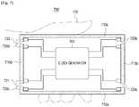
- FIG. 7 is a diagram illustrating an example of a horizontally gripped state of an electronic device according to various example embodiments.
- the gripped state of an electronic device may depend on the size of the electronic device and the size of the user's hand using the electronic device.
- FIG. 7 illustrates a situation in which a loop structure formed at two adjacent separators on a side of the electronic device of fourth separators can be sensed when a user horizontally holds an electronic device with a hand.
- a first signal generated by the clock generator 701 is transmitted to an electrically connected metallic part 710d and at least a portion of the first signal is transmitted to the metallic part 710a (721) by the left hand of the user 730 touching the two separators 720c and 720d, whereby a loop structure can be formed. Further, at least a portion of the first signal is transmitted to a metallic part 710c (722), so a loop structure can be formed.
- the electronic device 700 can determine a grip by the user's left hand based on the loop structure formed at the two separators 720c and 720d.
- a user 730 holds the electronic device 700 with a right hand, it is possible to sense that a loop structure is formed at two separators 720a and 720b on the top of the electronic device 700.
- the electronic device 700 can determine a grip by the user's right hand based on the loop structure formed at the two separators 720a and 720b.
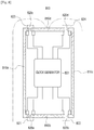
- FIG. 8 is a diagram illustrating an example of a gripped state of an erected electronic device according to various example embodiments.
- an electronic device 800 may include fourth metallic parts 810a, 810b, 810c, and 810d and four separators 820a, 820b, 820c, and 820d.
- the electronic device 800 can sense current loop structure at all of the four separators 820a, 820b, 820c, and 820d. For example, a first signal generated by a clock generator 801 can be transmitted to the electrically connected four metallic parts 810a, 810b, 810c, and 810d from the clock generator 801.
- At least a portion of the first signal transmitted to the first metallic part 810a can be transmitted to the second metallic part 810b (821) by the loop structure formed at the first separator 820a, at least a portion of the first signal transmitted to the second metallic part 810b can be transmitted to the third metallic part 810c (822) by the loop structure formed at the second separator 820b, at least a portion of the first signal transmitted to the third metallic part 810c can be transmitted to the fourth metallic part 810d (824) by the loop structure formed at the fourth separator 820d, and at least a portion of the first signal transmitted to the fourth metallic part 810d can be transmitted to the first metallic part 810a (823) by the loop structure formed at the third separator 820c.
- the electronic device 800 when the electronic device 800 is put on the legs 830 of a user, the electronic device 800 can determine that it is on the legs 830 of the user by sensing the loop structures formed at the first separator 820a to the fourth separator 820d.
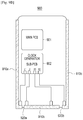
- FIGS. 9A , 9B and 9C are diagrams illustrating examples of a clock generator of an electronic device according to various example embodiments.
- a clock generator 910 e.g., the clock generator 202 in FIG. 2
- an electronic device 900 e.g., the electronic device 200 in FIG. 2
- the clock generator 901 may be mounted on a main PCB of the electronic device 900.
- Wires electrically connecting the clock generator 901 to metallic parts 910a, 910b, and 910c may be provided and separators 920a and 920b may be disposed respectively between adjacent two of the metallic parts 910a, 910b, and 910c.
- the electronic device 900 may include a main PCB 901 and a sub-PCB 902.
- a clock generator 902 may be mounted on the sub-PCB 902 of the electronic device 900.
- Wires electrically connecting the clock generator 902 to metallic parts 910a, 910b, and 910c may be provided and separators 920a and 920b may be disposed respectively between adjacent two of the metallic parts 910a, 910b, and 910c.
- the electronic device 900 may include a main PCB 901, a sub-PCB 902, and an NFC circuit 903.
- a clock generator 903 may be mounted on the NFC circuit 903 of the electronic device 900. Wires electrically connecting the clock generator 903 to metallic parts 910a, 910b, and 910c may be provided and separators 920a and 920b may be disposed respectively between adjacent two of the metallic parts 910a, 910b, and 910c.
- FIGS. 9A , 9B and 9C are examples and, according to various embodiments, a clock generator and wires electrically connected to clock generator to metallic parts may be freely disposed at predetermined positions in a housing of the electronic device 900.
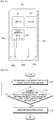
- FIG. 10 is a flowchart illustrating an example method of sensing a grip of an electronic device (e.g., the electronic device 200 or the processor 201 in FIG. 2 ).
- an electronic device e.g., the electronic device 200 or the processor 201 in FIG. 2 .
- a first signal generated by a clock generator (e.g., the clock generator 202 in FIG. 2 ) of the electronic device 200 can be transmitted to a first metallic part of a plurality of metallic parts included in a housing of the electronic device 200.
- at least one of the metallic parts may be an antenna.
- the antennas can support wireless communication at different frequency bands.
- the frequency of the first signal may be set within the range of 1MHz to 13MHz.
- the clock generator 202 is electrically connected to the first metallic part, and a first capacitor and a first inductor are disposed between the clock generator 202 and the first metallic part.
- the clock generator 202 is electrically connected to the second metallic part, and a second capacitor and a second inductor are disposed between the clock generator 202 and the second metallic part.
- the processor 201 determines whether a current loop is formed at the first metallic part, at the separator between the first metallic part and the second metallic part, and at the second metallic part based on the first signal. According to various embodiments, the processor 201 can determine that a current loop is formed when the difference of a loss between the first signal transmitted to the first metallic part and the first signal transmitted to the second metallic part is less than a threshold value.
- the threshold value can be set based on experimental data. According to various embodiments, it is possible to accurately sense a grip on an electronic device by a user's hand by setting a threshold value on the basis of the degrees of losses of signals measured in various situations, as shown in Table 3.
- the processor 201 senses a grip on the electronic device 200 while the first metallic part and the second metallic part form a loop structure through a separator. According to various embodiments, the processor 201 can determine the position of a grip on the electronic device based on the positions of separators. For example, when a current loop structure is formed at the right separator on the top of the electronic device 200, it is possible to determine that the right side of the top of the electronic device 200 has been gripped. According to various embodiments, the processor 201 can determine the intensity of a grip on the electronic device based on the difference first amplitude of the first signal at the first metallic part and second amplitude of the first signal at the second metallic part.
- the processor 201 can reduce the output voltage of the antennas in the electronic device 200 based on the grip sensed in operation 1103. For example, when a grip on the electronic device by a user's right hand is sensed, it is possible to reduce the output voltage of the antennas to a level that satisfies standard authentication of electromagnetic wave absorption rate.
- the processor 201 can change the resonance frequency of the antennas in the electronic device 200 based on the grip sensed in operation 1103. For example, it is possible to set different resonance frequency of antennas, depending on a grip on an electronic device by a user's right hand and a grip on the electronic device by a user's left hand, whereby the antenna efficiency can be improved.
Landscapes
- Engineering & Computer Science (AREA)
- Theoretical Computer Science (AREA)
- Computer Hardware Design (AREA)
- General Engineering & Computer Science (AREA)
- Physics & Mathematics (AREA)
- General Physics & Mathematics (AREA)
- Human Computer Interaction (AREA)
- Computer Networks & Wireless Communication (AREA)
- Signal Processing (AREA)
- Power Engineering (AREA)
- Environmental & Geological Engineering (AREA)
- User Interface Of Digital Computer (AREA)
Claims (11)
- Elektronische Vorrichtung, die Folgendes umfasst:ein Gehäuse;eine Vielzahl von Metallteilen (210a, 210b), die einen Abschnitt des Gehäuses bilden;einen Taktgenerator (202), der in dem Gehäuse angeordnet ist; undeinen Prozessor (201),wobei der Prozessor (201) konfiguriert ist, um einen Griff an der elektronischen Vorrichtung (200) basierend auf einer Stromschleife zu erfassen, die durch ein erstes Signal gebildet wird, das von dem Taktgenerator (202) erzeugt und durch ein erstes Metallteil (210a) und ein zweites Metallteil (210b) aus der Vielzahl der Metallteile übertragen wird,wobei das zweite Metallteil (210b) benachbart zu dem ersten Metallteil (210a) angeordnet ist, wobei ein erster Separator (220a) zwischen dem ersten Metallteil (210a) und dem zweiten Metallteil (210b) angeordnet ist und konfiguriert ist, um das erste Metallteil (210a) und das zweite Metallteil (210b) elektrisch zu trennen,wobei mindestens eines aus der Vielzahl von Metallteilen (210a, 210b) eine Antenne umfasst,wobei der Taktgenerator (202) elektrisch mit dem ersten Metallteil (210a) verbunden ist,wobei die elektronische Vorrichtung (200) ferner einen ersten Kondensator (230a) und einen ersten Induktor (240a) umfasst, die zwischen dem Taktgenerator (202) und dem ersten Metallteil (210a) angeordnet sind, wobei der erste Kondensator (230a) konfiguriert ist, um eine Leckage zu verhindern, während von dem Taktgenerator (202) erzeugte Signale an das erste Metallteil (210a) übertragen werden,wobei der Taktgenerator (202) elektrisch mit dem zweiten Metallteil (210b) verbunden ist,wobei die elektronische Vorrichtung (200) ferner einen zweiten Kondensator (230b) und einen zweiten Induktor (240b) umfasst, die zwischen dem Taktgenerator (202) und dem zweiten Metallteil (210b) angeordnet sind, wobei der zweite Kondensator (230b) konfiguriert ist, um eine Leckage zu verhindern, während von dem Taktgenerator (202) erzeugte Signale an das zweite Metallteil (210b) übertragen werden,wobei der Prozessor (201) konfiguriert ist, um zu bestimmen, dass die Stromschleife gebildet wird, wenn ein wegen des ersten Separators (220a) auftretender Signalverlust des ersten Signals in der Stromschleife kleiner als ein Standardverlust ist.
- Elektronische Vorrichtung nach Anspruch 1, wobei der Prozessor (201) konfiguriert ist, um die Position eines Griffs an der elektronischen Vorrichtung (200) basierend auf einer Position des ersten Separators (220a) zu bestimmen.
- Elektronische Vorrichtung nach Anspruch 1, wobei der Prozessor (201) konfiguriert ist, um eine Intensität eines Griffs an der elektronischen Vorrichtung (200) basierend auf dem wegen des ersten Separators (220a) auftretenden Signalverlust des ersten Signals in der Stromschleife zu bestimmen.
- Elektronische Vorrichtung nach Anspruch 1, wobei eine Frequenz des ersten Signals in einem Bereich von 1 MHz bis 13 MHz liegt.
- Elektronische Vorrichtung nach Anspruch 1, wobei der Prozessor (201) konfiguriert ist, um eine Ausgangsspannung der Antenne basierend auf dem erfassten Griff zu reduzieren.
- Elektronische Vorrichtung nach Anspruch 1, wobei der Prozessor (201) konfiguriert ist, um eine Resonanzfrequenz der Antenne basierend auf dem erfassten Griff zu ändern.
- Elektronische Vorrichtung nach Anspruch 1, wobei der erste Separator (220a) ein nicht leitendes Element umfasst.
- Verfahren zum Erfassen eines Griffs an einer elektronischen Vorrichtung, wobei das Verfahren Folgendes umfasst:Übertragen eines ersten Signals, das von einem Taktgenerator erzeugt wird, der in einer elektronischen Vorrichtung enthalten ist, an ein erstes Metallteil aus einer Vielzahl von Metallteilen, die einen Abschnitt eines Gehäuses der elektronischen Vorrichtung (1101) bilden;Erfassen eines Griffs an der elektronischen Vorrichtung basierend auf einer Stromschleife (1103), die durch das erste Signal gebildet wird, das durch das erste Metallteil und ein zweites Metallteil aus der Vielzahl von Metallteilen übertragen wird;wobei das zweite Metallteil benachbart zu dem ersten Metallteil angeordnet ist, wobei ein erster Separator zwischen dem ersten Metallteil und dem zweiten Metallteil angeordnet ist und konfiguriert ist, um das erste Metallteil und das zweite Metallteil elektrisch zu trennen;Bestimmen, dass die Stromschleife gebildet wird, wenn ein wegen des ersten Separators auftretender Signalverlust des ersten Signals in der Stromschleife kleiner als ein Standardverlust (1102) ist; undwobei mindestens eines aus der Vielzahl von Metallteilen eine Antenne umfasst,wobei der Taktgenerator elektrisch mit dem ersten Metallteil verbunden ist,wobei ein erster Kondensator und ein erster Induktor zwischen dem Taktgenerator und dem ersten Metallteil angeordnet sind, wobei der erste Kondensator konfiguriert ist, um eine Leckage zu verhindern, während von dem Taktgenerator erzeugte Signale an das erste Metallteil übertragen werden,wobei der Taktgenerator elektrisch mit dem zweiten Metallteil verbunden ist,wobei ein zweiter Kondensator und ein zweiter Induktor zwischen dem Taktgenerator und dem zweiten Metallteil angeordnet sind, wobei der zweite Kondensator konfiguriert ist, um eine Leckage zu verhindern, während von dem Taktgenerator erzeugte Signale an das zweite Metallteil übertragen werden.
- Verfahren nach Anspruch 8, wobei eine Frequenz des ersten Signals in einem Bereich von 1 MHz bis 13 MHz liegt.
- Verfahren nach Anspruch 8, ferner umfassend das Bestimmen einer Position eines Griffs an der elektronischen Vorrichtung basierend auf einer Position des ersten Separators.
- Verfahren nach Anspruch 8, ferner umfassend das Bestimmen einer Intensität eines Griffs an der elektronischen Vorrichtung basierend auf dem wegen des ersten Separators auftretenden Signalverlust des ersten Signals in der Stromschleife.
Applications Claiming Priority (2)
| Application Number | Priority Date | Filing Date | Title |
|---|---|---|---|
| KR1020170127968A KR102426351B1 (ko) | 2017-09-29 | 2017-09-29 | 그립 센싱을 위한 전자 장치 및 그 동작 방법 |
| PCT/KR2018/011546 WO2019066564A1 (en) | 2017-09-29 | 2018-09-28 | ELECTRONIC ENTRY DETECTION DEVICE AND METHOD OF OPERATION |
Publications (3)
| Publication Number | Publication Date |
|---|---|
| EP3673582A1 EP3673582A1 (de) | 2020-07-01 |
| EP3673582A4 EP3673582A4 (de) | 2020-09-02 |
| EP3673582B1 true EP3673582B1 (de) | 2021-12-01 |
Family
ID=65896902
Family Applications (1)
| Application Number | Title | Priority Date | Filing Date |
|---|---|---|---|
| EP18862745.9A Not-in-force EP3673582B1 (de) | 2017-09-29 | 2018-09-28 | Elektronische vorrichtung zur grifferfassung und verfahren zu deren betrieb |
Country Status (4)
| Country | Link |
|---|---|
| US (1) | US10637128B2 (de) |
| EP (1) | EP3673582B1 (de) |
| KR (1) | KR102426351B1 (de) |
| WO (1) | WO2019066564A1 (de) |
Families Citing this family (8)
| Publication number | Priority date | Publication date | Assignee | Title |
|---|---|---|---|---|
| KR20210033842A (ko) * | 2019-09-19 | 2021-03-29 | 삼성전자주식회사 | 전자 장치 및 상기 전자 장치가 송신 전력을 제어하는 방법 |
| KR102417169B1 (ko) * | 2019-12-30 | 2022-07-06 | 주식회사 유라코퍼레이션 | 버스바 전개 시스템, 방법 및 컴퓨터 프로그램 |
| WO2022025594A1 (ko) | 2020-07-27 | 2022-02-03 | 삼성전자 주식회사 | 그립 센서를 포함하는 전자 장치에서 디스플레이의 확장 여부에 따라 전송 전력을 조절하는 장치 및 방법 |
| KR102902132B1 (ko) | 2020-09-04 | 2025-12-19 | 삼성전자 주식회사 | 커패시턴스 센서를 포함하는 전자 장치 |
| CN112821031B (zh) * | 2020-12-29 | 2024-01-02 | Oppo广东移动通信有限公司 | 电子设备 |
| WO2023214659A1 (ko) * | 2022-05-06 | 2023-11-09 | 삼성전자 주식회사 | 그립 센서를 포함하는 전자 장치 및 방법 |
| EP4598000A4 (de) * | 2022-10-12 | 2026-01-21 | Samsung Electronics Co Ltd | Antenne mit leitfähigen abschnitten und elektronische vorrichtung damit |
| WO2024123106A1 (ko) * | 2022-12-08 | 2024-06-13 | 삼성전자 주식회사 | 센싱 회로를 포함하는 롤러블 전자 장치 |
Family Cites Families (18)
| Publication number | Priority date | Publication date | Assignee | Title |
|---|---|---|---|---|
| US5736937A (en) * | 1995-09-12 | 1998-04-07 | Beta Monitors & Controls, Ltd. | Apparatus for wireless transmission of shaft position information |
| US7071837B2 (en) | 1999-07-07 | 2006-07-04 | Expro North Sea Limited | Data transmission in pipeline systems |
| KR100668341B1 (ko) | 2005-06-29 | 2007-01-12 | 삼성전자주식회사 | 사용자의 파지 형태를 이용한 휴대용 단말기의 기능 입력방법 및 장치. |
| WO2010115940A1 (en) | 2009-04-07 | 2010-10-14 | Ident Technology Ag | Sensor device and method for grip and proximity detection |
| CN103140820B (zh) | 2010-11-05 | 2016-11-09 | 微晶片科技德国公司 | 用于检测对手持式装置的抓握的方法及传感器装置 |
| KR101921205B1 (ko) * | 2011-02-10 | 2018-11-22 | 삼성전자 주식회사 | 통신 환경에 따른 단말기 제어 방법 및 이를 지원하는 휴대 단말기 |
| KR101801117B1 (ko) * | 2011-07-27 | 2017-11-27 | 삼성전자주식회사 | 휴대용 무선 단말기에서 안테나와 센서용 부재로 병행하는 금속체 및 이와 연동하는 장치 |
| US9692875B2 (en) | 2012-08-31 | 2017-06-27 | Analog Devices, Inc. | Grip detection and capacitive gesture system for mobile devices |
| US20140188561A1 (en) * | 2012-12-28 | 2014-07-03 | Arbitron Inc. | Audience Measurement System, Method and Apparatus with Grip Sensing |
| US20150205400A1 (en) | 2014-01-21 | 2015-07-23 | Microsoft Corporation | Grip Detection |
| US10122081B2 (en) * | 2014-03-13 | 2018-11-06 | Google Technology Holdings LLC | Hand grip sensor for external chassis antenna |
| EP2988479B1 (de) | 2014-08-19 | 2019-01-30 | Semtech Corporation | Kapazitiver näherungssensor und mobile vorrichtung |
| KR102242363B1 (ko) | 2014-09-11 | 2021-04-20 | 삼성전자주식회사 | 전자 장치 및 전자 장치에서 그립 센싱 방법 |
| US9490885B1 (en) * | 2015-05-01 | 2016-11-08 | Amazon Technologies, Inc. | Proximity sensor and antenna system arrangement for metal housing |
| KR102408870B1 (ko) | 2015-08-13 | 2022-06-15 | 삼성전자주식회사 | 안테나 장치 및 그것을 포함하는 전자 장치 |
| FR3053503B1 (fr) * | 2016-06-30 | 2019-03-29 | Stmicroelectronics (Rousset) Sas | Procede de protection d'un circuit integre, et circuit integre correspondant |
| CN106953648B (zh) * | 2017-02-28 | 2019-08-20 | 维沃移动通信有限公司 | 一种复用天线和天线复用的方法 |
| KR102376211B1 (ko) * | 2017-08-30 | 2022-03-21 | 삼성전자주식회사 | 그립 센서 및 안테나를 포함하는 전자 장치 |
-
2017
- 2017-09-29 KR KR1020170127968A patent/KR102426351B1/ko active Active
-
2018
- 2018-09-24 US US16/139,455 patent/US10637128B2/en active Active
- 2018-09-28 WO PCT/KR2018/011546 patent/WO2019066564A1/en not_active Ceased
- 2018-09-28 EP EP18862745.9A patent/EP3673582B1/de not_active Not-in-force
Also Published As
| Publication number | Publication date |
|---|---|
| WO2019066564A1 (en) | 2019-04-04 |
| KR102426351B1 (ko) | 2022-07-29 |
| US20190103659A1 (en) | 2019-04-04 |
| EP3673582A4 (de) | 2020-09-02 |
| EP3673582A1 (de) | 2020-07-01 |
| US10637128B2 (en) | 2020-04-28 |
| KR20190038023A (ko) | 2019-04-08 |
Similar Documents
| Publication | Publication Date | Title |
|---|---|---|
| US10637128B2 (en) | Electronic device for grip sensing and method for operating thereof | |
| CN110829616B (zh) | 用于控制与输入设备的通信连接的电子设备及其控制方法 | |
| US11047893B2 (en) | Antenna for electromagnetic interference detection and portable electronic device including the same | |
| KR102567412B1 (ko) | 복수의 레이어를 포함하는 차폐 필름 및 그것을 사용하는 전자 장치 | |
| US11490223B2 (en) | Method and electronic device for providing notification based on distance of remote input device | |
| CN120856820A (zh) | 天线以及包括该天线的可折叠电子装置 | |
| KR20190023995A (ko) | 그립 센서 및 안테나를 포함하는 전자 장치 | |
| EP3531810B1 (de) | Elektronische vorrichtung mit leitfähigem element zur formung einer kapazitiven kopplung mit klammer und elektrischer verbindung zu erdungen einer vielzahl von in der klammer angeordneten leiterplatten | |
| CN111656695B (zh) | 用于减少噪声的电子装置 | |
| US20210320504A1 (en) | Electronic device for controlling charging of multiple batteries connected in parallel and method for operating same | |
| CN105122195B (zh) | 一种信息处理方法及电子设备 | |
| KR20200085546A (ko) | 그립 센서를 이용하여 파워 백 오프를 제어하기 위한 방법 및 이를 지원하는 전자 장치 | |
| KR102831062B1 (ko) | 전자기기 | |
| CN116746070A (zh) | 用于控制通信模块的发射功率的电子装置和方法 | |
| CN119278594A (zh) | 电子装置及用于电子装置的天线输出功率控制方法 | |
| KR102408872B1 (ko) | 공진 주파수를 조정하는 회로 및 이를 포함하는 전자 장치 | |
| US9426557B2 (en) | Earphone system, earphone device, and portable terminal for supporting the same | |
| CN111726137B (zh) | 天线功率控制方法、装置及电子设备 | |
| US12562597B2 (en) | Wireless power transmission device, and electronic device comprising same | |
| CN110958345B (zh) | 移动终端后盖检测方法、装置及计算机可读存储介质 | |
| CN108649671A (zh) | 一种无线充电电路及可穿戴式设备 | |
| CN114375436B (zh) | 提供无线充电功能的电子装置及其操作方法 | |
| KR20200082101A (ko) | 도전성 부재에 관한 검출 회로를 포함하는 전자 장치 | |
| US12019814B2 (en) | Electronic device and electronic pen for input control and method thereof | |
| US12218439B2 (en) | Antenna and electronic device comprising same |
Legal Events
| Date | Code | Title | Description |
|---|---|---|---|
| STAA | Information on the status of an ep patent application or granted ep patent |
Free format text: STATUS: THE INTERNATIONAL PUBLICATION HAS BEEN MADE |
|
| PUAI | Public reference made under article 153(3) epc to a published international application that has entered the european phase |
Free format text: ORIGINAL CODE: 0009012 |
|
| STAA | Information on the status of an ep patent application or granted ep patent |
Free format text: STATUS: REQUEST FOR EXAMINATION WAS MADE |
|
| 17P | Request for examination filed |
Effective date: 20200323 |
|
| AK | Designated contracting states |
Kind code of ref document: A1 Designated state(s): AL AT BE BG CH CY CZ DE DK EE ES FI FR GB GR HR HU IE IS IT LI LT LU LV MC MK MT NL NO PL PT RO RS SE SI SK SM TR |
|
| AX | Request for extension of the european patent |
Extension state: BA ME |
|
| A4 | Supplementary search report drawn up and despatched |
Effective date: 20200730 |
|
| RIC1 | Information provided on ipc code assigned before grant |
Ipc: H04B 1/401 20150101ALI20200724BHEP Ipc: H01Q 1/24 20060101ALI20200724BHEP Ipc: H04B 1/3827 20150101AFI20200724BHEP |
|
| DAV | Request for validation of the european patent (deleted) | ||
| DAX | Request for extension of the european patent (deleted) | ||
| REG | Reference to a national code |
Ref country code: DE Ref legal event code: R079 Ref document number: 602018027714 Country of ref document: DE Free format text: PREVIOUS MAIN CLASS: H04B0001382700 Ipc: H01Q0001240000 |
|
| RIC1 | Information provided on ipc code assigned before grant |
Ipc: H01Q 1/24 20060101AFI20210512BHEP Ipc: G06F 1/16 20060101ALI20210512BHEP Ipc: H03K 17/955 20060101ALI20210512BHEP Ipc: H04M 1/02 20060101ALN20210512BHEP Ipc: H04M 1/72 20210101ALN20210512BHEP |
|
| GRAP | Despatch of communication of intention to grant a patent |
Free format text: ORIGINAL CODE: EPIDOSNIGR1 |
|
| STAA | Information on the status of an ep patent application or granted ep patent |
Free format text: STATUS: GRANT OF PATENT IS INTENDED |
|
| INTG | Intention to grant announced |
Effective date: 20210629 |
|
| GRAS | Grant fee paid |
Free format text: ORIGINAL CODE: EPIDOSNIGR3 |
|
| GRAA | (expected) grant |
Free format text: ORIGINAL CODE: 0009210 |
|
| STAA | Information on the status of an ep patent application or granted ep patent |
Free format text: STATUS: THE PATENT HAS BEEN GRANTED |
|
| AK | Designated contracting states |
Kind code of ref document: B1 Designated state(s): AL AT BE BG CH CY CZ DE DK EE ES FI FR GB GR HR HU IE IS IT LI LT LU LV MC MK MT NL NO PL PT RO RS SE SI SK SM TR |
|
| REG | Reference to a national code |
Ref country code: GB Ref legal event code: FG4D |
|
| REG | Reference to a national code |
Ref country code: AT Ref legal event code: REF Ref document number: 1452671 Country of ref document: AT Kind code of ref document: T Effective date: 20211215 Ref country code: CH Ref legal event code: EP |
|
| REG | Reference to a national code |
Ref country code: IE Ref legal event code: FG4D |
|
| REG | Reference to a national code |
Ref country code: DE Ref legal event code: R096 Ref document number: 602018027714 Country of ref document: DE |
|
| REG | Reference to a national code |
Ref country code: LT Ref legal event code: MG9D |
|
| REG | Reference to a national code |
Ref country code: NL Ref legal event code: MP Effective date: 20211201 |
|
| REG | Reference to a national code |
Ref country code: AT Ref legal event code: MK05 Ref document number: 1452671 Country of ref document: AT Kind code of ref document: T Effective date: 20211201 |
|
| PG25 | Lapsed in a contracting state [announced via postgrant information from national office to epo] |
Ref country code: RS Free format text: LAPSE BECAUSE OF FAILURE TO SUBMIT A TRANSLATION OF THE DESCRIPTION OR TO PAY THE FEE WITHIN THE PRESCRIBED TIME-LIMIT Effective date: 20211201 Ref country code: LT Free format text: LAPSE BECAUSE OF FAILURE TO SUBMIT A TRANSLATION OF THE DESCRIPTION OR TO PAY THE FEE WITHIN THE PRESCRIBED TIME-LIMIT Effective date: 20211201 Ref country code: FI Free format text: LAPSE BECAUSE OF FAILURE TO SUBMIT A TRANSLATION OF THE DESCRIPTION OR TO PAY THE FEE WITHIN THE PRESCRIBED TIME-LIMIT Effective date: 20211201 Ref country code: BG Free format text: LAPSE BECAUSE OF FAILURE TO SUBMIT A TRANSLATION OF THE DESCRIPTION OR TO PAY THE FEE WITHIN THE PRESCRIBED TIME-LIMIT Effective date: 20220301 Ref country code: AT Free format text: LAPSE BECAUSE OF FAILURE TO SUBMIT A TRANSLATION OF THE DESCRIPTION OR TO PAY THE FEE WITHIN THE PRESCRIBED TIME-LIMIT Effective date: 20211201 |
|
| PG25 | Lapsed in a contracting state [announced via postgrant information from national office to epo] |
Ref country code: SE Free format text: LAPSE BECAUSE OF FAILURE TO SUBMIT A TRANSLATION OF THE DESCRIPTION OR TO PAY THE FEE WITHIN THE PRESCRIBED TIME-LIMIT Effective date: 20211201 Ref country code: PL Free format text: LAPSE BECAUSE OF FAILURE TO SUBMIT A TRANSLATION OF THE DESCRIPTION OR TO PAY THE FEE WITHIN THE PRESCRIBED TIME-LIMIT Effective date: 20211201 Ref country code: NO Free format text: LAPSE BECAUSE OF FAILURE TO SUBMIT A TRANSLATION OF THE DESCRIPTION OR TO PAY THE FEE WITHIN THE PRESCRIBED TIME-LIMIT Effective date: 20220301 Ref country code: LV Free format text: LAPSE BECAUSE OF FAILURE TO SUBMIT A TRANSLATION OF THE DESCRIPTION OR TO PAY THE FEE WITHIN THE PRESCRIBED TIME-LIMIT Effective date: 20211201 Ref country code: HR Free format text: LAPSE BECAUSE OF FAILURE TO SUBMIT A TRANSLATION OF THE DESCRIPTION OR TO PAY THE FEE WITHIN THE PRESCRIBED TIME-LIMIT Effective date: 20211201 Ref country code: GR Free format text: LAPSE BECAUSE OF FAILURE TO SUBMIT A TRANSLATION OF THE DESCRIPTION OR TO PAY THE FEE WITHIN THE PRESCRIBED TIME-LIMIT Effective date: 20220302 Ref country code: ES Free format text: LAPSE BECAUSE OF FAILURE TO SUBMIT A TRANSLATION OF THE DESCRIPTION OR TO PAY THE FEE WITHIN THE PRESCRIBED TIME-LIMIT Effective date: 20211201 |
|
| PG25 | Lapsed in a contracting state [announced via postgrant information from national office to epo] |
Ref country code: NL Free format text: LAPSE BECAUSE OF FAILURE TO SUBMIT A TRANSLATION OF THE DESCRIPTION OR TO PAY THE FEE WITHIN THE PRESCRIBED TIME-LIMIT Effective date: 20211201 |
|
| PG25 | Lapsed in a contracting state [announced via postgrant information from national office to epo] |
Ref country code: SM Free format text: LAPSE BECAUSE OF FAILURE TO SUBMIT A TRANSLATION OF THE DESCRIPTION OR TO PAY THE FEE WITHIN THE PRESCRIBED TIME-LIMIT Effective date: 20211201 Ref country code: SK Free format text: LAPSE BECAUSE OF FAILURE TO SUBMIT A TRANSLATION OF THE DESCRIPTION OR TO PAY THE FEE WITHIN THE PRESCRIBED TIME-LIMIT Effective date: 20211201 Ref country code: RO Free format text: LAPSE BECAUSE OF FAILURE TO SUBMIT A TRANSLATION OF THE DESCRIPTION OR TO PAY THE FEE WITHIN THE PRESCRIBED TIME-LIMIT Effective date: 20211201 Ref country code: PT Free format text: LAPSE BECAUSE OF FAILURE TO SUBMIT A TRANSLATION OF THE DESCRIPTION OR TO PAY THE FEE WITHIN THE PRESCRIBED TIME-LIMIT Effective date: 20220401 Ref country code: EE Free format text: LAPSE BECAUSE OF FAILURE TO SUBMIT A TRANSLATION OF THE DESCRIPTION OR TO PAY THE FEE WITHIN THE PRESCRIBED TIME-LIMIT Effective date: 20211201 Ref country code: CZ Free format text: LAPSE BECAUSE OF FAILURE TO SUBMIT A TRANSLATION OF THE DESCRIPTION OR TO PAY THE FEE WITHIN THE PRESCRIBED TIME-LIMIT Effective date: 20211201 |
|
| REG | Reference to a national code |
Ref country code: DE Ref legal event code: R097 Ref document number: 602018027714 Country of ref document: DE |
|
| PG25 | Lapsed in a contracting state [announced via postgrant information from national office to epo] |
Ref country code: IS Free format text: LAPSE BECAUSE OF FAILURE TO SUBMIT A TRANSLATION OF THE DESCRIPTION OR TO PAY THE FEE WITHIN THE PRESCRIBED TIME-LIMIT Effective date: 20220401 |
|
| PLBE | No opposition filed within time limit |
Free format text: ORIGINAL CODE: 0009261 |
|
| STAA | Information on the status of an ep patent application or granted ep patent |
Free format text: STATUS: NO OPPOSITION FILED WITHIN TIME LIMIT |
|
| PG25 | Lapsed in a contracting state [announced via postgrant information from national office to epo] |
Ref country code: DK Free format text: LAPSE BECAUSE OF FAILURE TO SUBMIT A TRANSLATION OF THE DESCRIPTION OR TO PAY THE FEE WITHIN THE PRESCRIBED TIME-LIMIT Effective date: 20211201 Ref country code: AL Free format text: LAPSE BECAUSE OF FAILURE TO SUBMIT A TRANSLATION OF THE DESCRIPTION OR TO PAY THE FEE WITHIN THE PRESCRIBED TIME-LIMIT Effective date: 20211201 |
|
| PGFP | Annual fee paid to national office [announced via postgrant information from national office to epo] |
Ref country code: DE Payment date: 20220822 Year of fee payment: 5 |
|
| 26N | No opposition filed |
Effective date: 20220902 |
|
| PG25 | Lapsed in a contracting state [announced via postgrant information from national office to epo] |
Ref country code: SI Free format text: LAPSE BECAUSE OF FAILURE TO SUBMIT A TRANSLATION OF THE DESCRIPTION OR TO PAY THE FEE WITHIN THE PRESCRIBED TIME-LIMIT Effective date: 20211201 |
|
| PG25 | Lapsed in a contracting state [announced via postgrant information from national office to epo] |
Ref country code: MC Free format text: LAPSE BECAUSE OF FAILURE TO SUBMIT A TRANSLATION OF THE DESCRIPTION OR TO PAY THE FEE WITHIN THE PRESCRIBED TIME-LIMIT Effective date: 20211201 |
|
| REG | Reference to a national code |
Ref country code: CH Ref legal event code: PL |
|
| GBPC | Gb: european patent ceased through non-payment of renewal fee |
Effective date: 20220928 |
|
| REG | Reference to a national code |
Ref country code: BE Ref legal event code: MM Effective date: 20220930 |
|
| PG25 | Lapsed in a contracting state [announced via postgrant information from national office to epo] |
Ref country code: IT Free format text: LAPSE BECAUSE OF FAILURE TO SUBMIT A TRANSLATION OF THE DESCRIPTION OR TO PAY THE FEE WITHIN THE PRESCRIBED TIME-LIMIT Effective date: 20211201 |
|
| PG25 | Lapsed in a contracting state [announced via postgrant information from national office to epo] |
Ref country code: LU Free format text: LAPSE BECAUSE OF NON-PAYMENT OF DUE FEES Effective date: 20220928 |
|
| PG25 | Lapsed in a contracting state [announced via postgrant information from national office to epo] |
Ref country code: LI Free format text: LAPSE BECAUSE OF NON-PAYMENT OF DUE FEES Effective date: 20220930 Ref country code: IE Free format text: LAPSE BECAUSE OF NON-PAYMENT OF DUE FEES Effective date: 20220928 Ref country code: FR Free format text: LAPSE BECAUSE OF NON-PAYMENT OF DUE FEES Effective date: 20220930 Ref country code: CH Free format text: LAPSE BECAUSE OF NON-PAYMENT OF DUE FEES Effective date: 20220930 |
|
| PG25 | Lapsed in a contracting state [announced via postgrant information from national office to epo] |
Ref country code: BE Free format text: LAPSE BECAUSE OF NON-PAYMENT OF DUE FEES Effective date: 20220930 |
|
| PG25 | Lapsed in a contracting state [announced via postgrant information from national office to epo] |
Ref country code: GB Free format text: LAPSE BECAUSE OF NON-PAYMENT OF DUE FEES Effective date: 20220928 |
|
| REG | Reference to a national code |
Ref country code: DE Ref legal event code: R119 Ref document number: 602018027714 Country of ref document: DE |
|
| PG25 | Lapsed in a contracting state [announced via postgrant information from national office to epo] |
Ref country code: CY Free format text: LAPSE BECAUSE OF FAILURE TO SUBMIT A TRANSLATION OF THE DESCRIPTION OR TO PAY THE FEE WITHIN THE PRESCRIBED TIME-LIMIT Effective date: 20211201 |
|
| PG25 | Lapsed in a contracting state [announced via postgrant information from national office to epo] |
Ref country code: MK Free format text: LAPSE BECAUSE OF FAILURE TO SUBMIT A TRANSLATION OF THE DESCRIPTION OR TO PAY THE FEE WITHIN THE PRESCRIBED TIME-LIMIT Effective date: 20211201 Ref country code: HU Free format text: LAPSE BECAUSE OF FAILURE TO SUBMIT A TRANSLATION OF THE DESCRIPTION OR TO PAY THE FEE WITHIN THE PRESCRIBED TIME-LIMIT; INVALID AB INITIO Effective date: 20180928 |
|
| PG25 | Lapsed in a contracting state [announced via postgrant information from national office to epo] |
Ref country code: DE Free format text: LAPSE BECAUSE OF NON-PAYMENT OF DUE FEES Effective date: 20240403 |
|
| PG25 | Lapsed in a contracting state [announced via postgrant information from national office to epo] |
Ref country code: MT Free format text: LAPSE BECAUSE OF FAILURE TO SUBMIT A TRANSLATION OF THE DESCRIPTION OR TO PAY THE FEE WITHIN THE PRESCRIBED TIME-LIMIT Effective date: 20211201 |
|
| PG25 | Lapsed in a contracting state [announced via postgrant information from national office to epo] |
Ref country code: TR Free format text: LAPSE BECAUSE OF FAILURE TO SUBMIT A TRANSLATION OF THE DESCRIPTION OR TO PAY THE FEE WITHIN THE PRESCRIBED TIME-LIMIT Effective date: 20211201 |