EP3673525B1 - System zum befestigen von kühlelementen - Google Patents
System zum befestigen von kühlelementen Download PDFInfo
- Publication number
- EP3673525B1 EP3673525B1 EP18756154.3A EP18756154A EP3673525B1 EP 3673525 B1 EP3673525 B1 EP 3673525B1 EP 18756154 A EP18756154 A EP 18756154A EP 3673525 B1 EP3673525 B1 EP 3673525B1
- Authority
- EP
- European Patent Office
- Prior art keywords
- elements
- component
- cooling
- rail
- heating elements
- Prior art date
- Legal status (The legal status is an assumption and is not a legal conclusion. Google has not performed a legal analysis and makes no representation as to the accuracy of the status listed.)
- Active
Links
Images


Classifications
-
- H—ELECTRICITY
- H01—ELECTRIC ELEMENTS
- H01M—PROCESSES OR MEANS, e.g. BATTERIES, FOR THE DIRECT CONVERSION OF CHEMICAL ENERGY INTO ELECTRICAL ENERGY
- H01M10/00—Secondary cells; Manufacture thereof
- H01M10/60—Heating or cooling; Temperature control
- H01M10/61—Types of temperature control
- H01M10/613—Cooling or keeping cold
-
- F—MECHANICAL ENGINEERING; LIGHTING; HEATING; WEAPONS; BLASTING
- F16—ENGINEERING ELEMENTS AND UNITS; GENERAL MEASURES FOR PRODUCING AND MAINTAINING EFFECTIVE FUNCTIONING OF MACHINES OR INSTALLATIONS; THERMAL INSULATION IN GENERAL
- F16B—DEVICES FOR FASTENING OR SECURING CONSTRUCTIONAL ELEMENTS OR MACHINE PARTS TOGETHER, e.g. NAILS, BOLTS, CIRCLIPS, CLAMPS, CLIPS OR WEDGES; JOINTS OR JOINTING
- F16B11/00—Connecting constructional elements or machine parts by sticking or pressing them together, e.g. cold pressure welding
- F16B11/006—Connecting constructional elements or machine parts by sticking or pressing them together, e.g. cold pressure welding by gluing
-
- H—ELECTRICITY
- H01—ELECTRIC ELEMENTS
- H01M—PROCESSES OR MEANS, e.g. BATTERIES, FOR THE DIRECT CONVERSION OF CHEMICAL ENERGY INTO ELECTRICAL ENERGY
- H01M10/00—Secondary cells; Manufacture thereof
- H01M10/04—Construction or manufacture in general
-
- H—ELECTRICITY
- H01—ELECTRIC ELEMENTS
- H01M—PROCESSES OR MEANS, e.g. BATTERIES, FOR THE DIRECT CONVERSION OF CHEMICAL ENERGY INTO ELECTRICAL ENERGY
- H01M10/00—Secondary cells; Manufacture thereof
- H01M10/60—Heating or cooling; Temperature control
- H01M10/65—Means for temperature control structurally associated with the cells
- H01M10/655—Solid structures for heat exchange or heat conduction
-
- H—ELECTRICITY
- H01—ELECTRIC ELEMENTS
- H01M—PROCESSES OR MEANS, e.g. BATTERIES, FOR THE DIRECT CONVERSION OF CHEMICAL ENERGY INTO ELECTRICAL ENERGY
- H01M10/00—Secondary cells; Manufacture thereof
- H01M10/60—Heating or cooling; Temperature control
- H01M10/62—Heating or cooling; Temperature control specially adapted for specific applications
- H01M10/625—Vehicles
-
- H—ELECTRICITY
- H01—ELECTRIC ELEMENTS
- H01M—PROCESSES OR MEANS, e.g. BATTERIES, FOR THE DIRECT CONVERSION OF CHEMICAL ENERGY INTO ELECTRICAL ENERGY
- H01M2220/00—Batteries for particular applications
- H01M2220/20—Batteries in motive systems, e.g. vehicle, ship, plane
-
- Y—GENERAL TAGGING OF NEW TECHNOLOGICAL DEVELOPMENTS; GENERAL TAGGING OF CROSS-SECTIONAL TECHNOLOGIES SPANNING OVER SEVERAL SECTIONS OF THE IPC; TECHNICAL SUBJECTS COVERED BY FORMER USPC CROSS-REFERENCE ART COLLECTIONS [XRACs] AND DIGESTS
- Y02—TECHNOLOGIES OR APPLICATIONS FOR MITIGATION OR ADAPTATION AGAINST CLIMATE CHANGE
- Y02E—REDUCTION OF GREENHOUSE GAS [GHG] EMISSIONS, RELATED TO ENERGY GENERATION, TRANSMISSION OR DISTRIBUTION
- Y02E60/00—Enabling technologies; Technologies with a potential or indirect contribution to GHG emissions mitigation
- Y02E60/10—Energy storage using batteries
-
- Y—GENERAL TAGGING OF NEW TECHNOLOGICAL DEVELOPMENTS; GENERAL TAGGING OF CROSS-SECTIONAL TECHNOLOGIES SPANNING OVER SEVERAL SECTIONS OF THE IPC; TECHNICAL SUBJECTS COVERED BY FORMER USPC CROSS-REFERENCE ART COLLECTIONS [XRACs] AND DIGESTS
- Y02—TECHNOLOGIES OR APPLICATIONS FOR MITIGATION OR ADAPTATION AGAINST CLIMATE CHANGE
- Y02P—CLIMATE CHANGE MITIGATION TECHNOLOGIES IN THE PRODUCTION OR PROCESSING OF GOODS
- Y02P70/00—Climate change mitigation technologies in the production process for final industrial or consumer products
- Y02P70/50—Manufacturing or production processes characterised by the final manufactured product
Definitions
- the invention relates to a system for attaching cooling elements to a component and a method for attaching cooling elements to a component.
- a vehicle may include a battery that stores electrical energy to propel the vehicle. It is necessary to cool the battery with a suitable cooling system, which, however, must be attached to the battery.
- a battery system with a thermally conductive battery housing and a heat dissipation system are from the publication DE 10 2014 004 742 A1 known.
- the heat dissipation system is glued to the battery housing.
- a battery cooling system that is known from the reference DE 10 2014 204 263 A1 is known, comprises a cooling plate, which consists of several plastic parts glued together.
- One in print DE 20 2012 101 076 U1 described device for cooling a battery comprises a cooling plate are bonded to the heat transfer means.
- the system according to the invention is designed for attaching cooling elements to a component that has a bottom and a top and has a base device, a gripping device and, in an embodiment, at least one application device for an adhesive connection.
- the basic device has a number of rows of heating elements, the heating elements being arranged side by side along a respective row.
- the gripping device has a corresponding number of rows of rail elements, the rail elements being arranged side by side along a respective row. In this case, an nth row with heating elements is congruent with an nth row with rail elements when the gripping device is arranged on the base device.
- the component To attach the cooling elements, the component must be placed with its underside on the heating elements.
- the at least one application device is designed to apply the adhesive compound in strips to an upper side of the component facing away from the base device, ie in strips and/or rows that are congruent with the rows along which the heating elements are arranged.
- the cooling elements are to be arranged along the rows of rail elements of the gripping device.
- the rail elements are designed to temporarily hold the cooling elements on the gripping device.
- the gripping device is designed to arrange the cooling elements on and/or along the strips of adhesive connection and to press against the upper side of the component or to press according to the definition.
- the heating elements are designed to warm up or heat the adhesive connection between the cooling elements and the upper side of the component along the rows to a temperature which is at least as great as a curing temperature of the adhesive connection.
- the heating elements will comprise induction coils for heating, or as defined, heating of the adhesive bond along the rows.
- Each rail element has at least one holding element and at least one pressure element, wherein the at least one holding element, for example a hydraulic suction element, is designed to temporarily hold at least one cooling element on the rail element.
- Each rail element has an elastically deformable body, for example made of rubber.
- the at least one pressure element is designed to press the rail element with at least one cooling element temporarily arranged thereon against the upper side of the component and to homogeneously distribute the adhesive bond between the at least one cooling element and the upper side.
- the cooling elements should be magnetic, it is possible that the holding elements have magnets, for example electromagnets, with magnetic fields that can be switched on and off, which are activated at least until the cooling elements are placed on the adhesive compound applied as strips along these strips and/or or arranged. The magnetic fields can be deactivated as soon as the induction coils are switched on.
- non-magnetic cooling elements must be held in place with suction elements.
- the base device and the gripping device each have positioning modules that can be connected to one another.
- the positioning modules connected to one another are designed to position the base device and the gripping device relative to one another and to arrange the nth row of heating elements congruently with the nth row of rail elements.
- the system has at least one clamping module that is fastened, fastened and/or to be fastened to the base device and/or the gripping device and is designed to clamp the base device and the gripping device to one another and thus to connect them.
- the at least one clamping module is arranged on the base device and/or the gripping device.
- the basic device and the gripping device can be connected to one another via several clamping modules.
- the clamping modules are designed to press the base device and the gripping device against one another. It is possible here for a definable distance for the adhesive connection to be adjustable between the upper side of the component and the outsides of the cooling elements.
- the basic device has support elements that are arranged on the heating elements and/or cover them.
- the component can be arranged on the support elements.
- one heating element is to be connected indirectly to the component by a support element arranged thereon, which forms a wall of the heating element, direct contact of the heating element with the component being avoided by the support element located between them.
- the component is arranged directly on the heating elements. If the system has the support elements, the component is to be arranged directly on the support elements and thus indirectly or indirectly on the heating elements.
- the method according to the invention is intended for fastening cooling elements on a component which has a bottom and a top.
- the method is carried out with an embodiment of the system according to the invention, which has a basic device, a gripping device and, in an embodiment, at least one application device for a Has adhesive connection.
- the basic device has a number of rows of heating elements, the heating elements being arranged along a respective row.
- the gripping device has a corresponding number of rows of rail elements, the rail elements being arranged along a respective row. In this case, an nth row with heating elements is congruent with an nth row of rail elements when the gripping device is arranged on the base device.
- the component is placed with its underside on the heating elements, with the adhesive connection being made with the at least one application device on the top side of the component facing away from the basic device in strips and/or as strips that are congruent with the rows along which the heating elements are arranged, applied or applied.
- strips of adhesive are applied to the component congruently with the rows of heating elements.
- the cooling elements are arranged along the rows of rail elements, the cooling elements being temporarily held with the rail elements on the gripping device.
- the cooling elements are arranged with the gripping device along the strips of adhesive connection and pressed against the top of the component.
- the adhesive joint is heated between the cooling elements and the upper side of the component with the heating elements to a temperature or, depending on the definition, heated which is at least as great as a curing temperature of the adhesive joint.
- the heating elements are turned off. Now it is possible to lift the gripping device.
- the cooling elements are now attached to the component. It is conceivable that the basic device has a cooling system with which the component is cooled with the cooling elements as soon as the adhesive connection has hardened.
- an adhesive compound which has two adhesive components which are mixed together and cure together when they have been heated to at least the curing temperature.
- cooling elements for example cooling fins or fins, are fastened to a component that is or is provided as part of a battery housing.
- the cooling elements and the top of the component with the strips of adhesive connection between them are pressed against one another between the rail elements and the heating elements, whereby a minimum distance for the adhesive connection is set and/or maintained between the cooling elements and the component.
- the system presented is designed to properly apply a thermally conductive adhesive or the adhesive compound, which has two adhesive components, in strips provided for this purpose and/or as strips provided for this purpose and then to join the cooling elements on the upper side of the component.
- the adhesive connection is pressed from the inside outwards with respect to a center line of a provided strip of the adhesive connection using an application device designed, for example, as an adhesive bead. If the adhesive connection has two adhesive components, it is possible to combine these two adhesive components with at least one To mix applicator and apply together on the top of the component.
- the adhesive compound is applied to the upper side of the component without air inclusions.
- a uniform adhesive gap is set for the adhesive connection between the top of the component and the outside of the cooling elements over the definable distance.
- the adhesive bond is warmed up or heated with the heating elements that are integrated into the basic device, with a hardening process for the adhesive bond being triggered.
- a strip of the adhesive compound or the adhesive compound hardens in its position within the adhesive gap along a respectively provided strip, which is congruent with both a respective row of heating elements and a respective row of rail elements.
- the system enables the cooling elements to be joined on the component, e.g consists of two adhesive components, to harden pore-free with an even adhesive gap of approx. 0.5 mm, e.g. 0.5 mm - 0.3 mm or 0.5 mm + 0.5 mm.
- the intended adhesive gap and its height are adjusted, among other things, by adjusting the distance between the heating elements and the clamping modules.
- the basic device forms a base on which the component is to be arranged, with the heating elements receiving the component.
- the basic device forms a counter-layer for pressing the adhesive connection.
- the heating elements of the basic device e.g. designed as induction coils, comprise square, e.g. rectangular, square and/or square-shaped copper lines or copper pipes, which are also designed to cool the heating elements as soon as the adhesive bond has hardened.
- the cooling elements are picked up by the gripping device, which is also designed and/or can be designated as the upper part of the system, with suction cups or suction elements of the rail elements.
- clamping modules or clamping units and the positioning modules which are each arranged on the sides of the base device and the gripping device, enable the base device and the gripping device to be positioned exactly one above the other, resulting in an nth row of rail elements and an nth row of heating elements to one another and/or relative to one another can be arranged congruently.
- surfaces of the heating elements form flat supports and/or have the support elements with which subsequent dimensional adjustment of a height or width of the adhesive gap for the adhesive connection is possible.
- the system and the method make it possible, for example, to arrange cooling elements on a housing of a battery for a vehicle, this battery being suitable for storing electrical energy for driving the vehicle, with electrical energy being chargeable into the battery and also being discharged again is.
- An external cooling system can be provided for the battery via the cooling elements on the housing of the battery, with which the battery is protected against overheating and thus against destruction.
- the rail elements to have elastic, generally hard-elastic pressure elements, with which the cooling elements can be pressed in the direction of the upper side of the component while maintaining the adhesive gap provided for the adhesive connection.
- the adhesive connection it is possible to adjust a pressure on the adhesive connection along the strip within the adhesive gap, taking into account an actual value provided here, to a respectively provided target value and thereby reducing the pressure, among other things. build up. Provision is also made for the adhesive connection to be heated usually inductively within the adhesive gap by the heating elements, it also being possible to adapt a current actual value of the temperature to a target value provided for this purpose, with the target value usually being at least as great as the curing temperature of the Adhesive connection is. However, it is also possible for a target value for the pressure and a target value for the temperature to be correlated with one another and/or coordinated with one another. In this way it is possible, for example, to cure the adhesive connection in an intended production time and thus in a corresponding period of time.
- the adhesive gap has a height or width of a fraction of a millimeter up to approximately one millimeter.
- a thermally conductive and mechanically stable for example hard-elastically deformable wall or a corresponding partition to be arranged as a support element on each heating element, on which the underside of the component is to be arranged.
- a respective heating element is designed as an induction coil and/or has such an induction coil, it is possible to space the underside of the component from a respective induction coil with the support element.
- a respective induction coil which is arranged along a respective row of heating elements, inductively generates eddy currents with which metallic modules, e.g. the component and/or the cooling elements, are heated, which in turn heats the adhesive connection between the cooling elements and the component.
- the adhesive connection is heated indirectly by the heating elements at least via the component and/or the cooling elements, with a temperature being heated within a defined, definable period of time to a desired value which, for example, is at least as high as the curing temperature. Furthermore, this temperature is maintained at the intended setpoint for a second period of time.
- the setpoint for the temperature corresponds to 80 °C, for example.
- the first period of time or a heating-up phase, during which the temperature of the adhesive bond is heated to the desired value lasts for example 40 seconds.
- the second period of time or a holding phase during which the temperature is kept at the desired value, lasts for example 200 seconds.
- a cooling system to influence the temperature of the adhesive bond during the process to be arranged in the basic device.
- This cooling system includes a recooler, with water, for example, being used as the coolant.
- a thermostatic pipe water regulation, a reservoir, an internal pressure pump for the coolant, as well as sensors for monitoring a temperature sensing level, a flow rate and a need for water as a cooling medium are provided. It is also possible to print the coolant to at least 3 bar, maximum 10 bar. A temperature of the coolant is, for example, 10 to 30°C.
- the adhesive compound is first applied or applied in the form of strips congruent to the rows of heating elements in a defined period of time on the upper side of the component. Thereafter, the cooling elements are also arranged within a definable period of time via the rail elements of the gripping device, also along the intended rows, which are congruent with the strips of the applied adhesive compound. During the process, only the adhesive bond is heated in a targeted manner along a respectively provided strip, which is congruent with a respective row of heating elements.
- the rail elements are comparatively hard, but are still slightly elastically flexible.
- the outsides of the cooling elements are glued over the surface as strips or along the strips provided for this purpose on the upper side of the component via the adhesive connection.
- the adhesive compound is applied to the upper side of the component along a respectively provided strip using an application device designed as a cooling bead.
- the heating elements are arranged in support elements and/or below support elements on which the component is arranged.
- the support elements are also arranged along rows corresponding to the heating elements integrated therein the support elements and the heating elements of an nth row are congruent with an nth row of the rail elements when the gripping device is or is arranged on the base device. Accordingly, the adhesive compound is to be applied along an nth strip, which is congruent with the nth row of heating elements and, if applicable, support elements.
- the Figures 1a and 1b show the basic device 2 as a lower part of the embodiment of the system according to the invention from different perspectives.
- the basic device 2 comprises at least one plate 4 along which several rows of support elements 6 are arranged.
- two outer rows each comprise two support elements 6, which are arranged one behind the other along a respective row.
- nine rows of support elements 6 are arranged on the plate 4, with three support elements 6 being arranged next to one another within a respective row along this row.
- each support element 6 covers a heating element designed as an induction coil and/or induction loop, with a respective support element 6 being designed as a cover or wall of a respective heating element. Accordingly, the heating elements in the figures are covered by the walls of the support elements 6 and cannot be seen.
- the heating elements are also arranged next to one another and/or one behind the other within a respective row of support elements 6 .
- a support element 6 encloses a heating element, usually its upper side, at least partially.
- a support element 6 is designed and/or designated as a housing of a heating element.
- support rods 8 are arranged on the plate 4, with a primary positioning module 10 being arranged on a respective support rod 8. It is envisaged that two support rods 8 and two primary positioning modules 10 each are arranged along a line, the rows of the support elements 6 and the heating elements are arranged between these two lines.
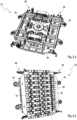
- FIG Figure 2a shows the gripping device 20 as the upper part of the system from above, whereas FIG Figure 2b shows the gripping device 20 from below.
- Eleven rows of rail elements 22 are arranged here on the underside of the gripping device 20 .
- Nine such rows each comprise three rail elements 22 arranged one behind the other along a respective row.
- Two further rows each with two rail elements 22 are provided, which delimit the other rows.
- the two rail elements 22 of a respective row are also arranged one behind the other and/or next to one another along the row.
- FIGS. 2a and 2b secondary positioning modules 24, which are arranged here on two outer sides of a supporting body 26, on which in turn the rows of rail elements 22 are arranged.
- four clamping modules 28 are arranged at corners of the support body 26 .
- a component 40 can be arranged on the support elements 6 and thus also on the heating elements of the basic device 2, which is provided here as part of a housing for a battery ( Figure 3a ).
- the gripping device 20 is arranged on the component 40 and thus also on the base device 2 . It is provided here that the primary positioning modules 10 of the base device 2 are arranged on the secondary positioning modules 24 of the support body 26, with the base device 2 and the gripping device 20 being positioned relative to one another and connected to one another via the positioning modules 10, 24.
- a row of support elements 6 and thus also of heating modules of the basic device 2 integrated therein are arranged congruently or congruently with a respective row of clamping modules 22 of the gripping device 20 .
- the component 40 is first arranged with its underside on the rows of support elements 6 and thus also on the rows of heating elements.
- An adhesive compound comprising two adhesive components is then applied with at least one application device 42 on the upper side of component 40 along a strip and/or as a strip that is congruent with a row of support elements 6 and heating elements of basic device 2.
- the gripping device 20 is arranged on the base device 2 and thus also on the component 40 . It is also provided that one strip of the adhesive connection is congruent with a row of cooling elements. A row of cooling elements is arranged congruently on each strip of the adhesive connection.
- a minimum distance for an adhesive gap of the adhesive connection is maintained via the positioning modules 10, 24 between an outside of a respective cooling element and the upper side of the component 40.
Landscapes
- Engineering & Computer Science (AREA)
- Manufacturing & Machinery (AREA)
- Chemical & Material Sciences (AREA)
- Chemical Kinetics & Catalysis (AREA)
- Electrochemistry (AREA)
- General Chemical & Material Sciences (AREA)
- General Engineering & Computer Science (AREA)
- Mechanical Engineering (AREA)
- Automatic Assembly (AREA)
- Adhesives Or Adhesive Processes (AREA)
- Secondary Cells (AREA)
- Container, Conveyance, Adherence, Positioning, Of Wafer (AREA)
Description
- Die Erfindung betrifft ein System zum Befestigen von Kühlelementen auf einem Bauteil und ein Verfahren zum Befestigen von Kühlelementen auf einem Bauteil.
- Ein Fahrzeug kann eine Batterie aufweisen, in der elektrische Energie zum Antreiben des Fahrzeugs gespeichert wird. Dabei ist es erforderlich, die Batterie durch ein geeignetes Kühlsystem zu kühlen, das jedoch an der Batterie zu befestigen ist.
- Ein Batteriesystem mit einem thermisch leitfähigen Batteriegehäuse und einem Wärmeabfuhrsystem sind aus der Druckschrift
DE 10 2014 004 742 A1 bekannt. Dabei ist das Wärmeabfuhrsystem mit dem Batteriegehäuse verklebt. - Ein Batteriekühlsystem, das aus der Druckschrift
DE 10 2014 204 263 A1 bekannt ist, umfasst eine Kühlplatte, die aus mehreren miteinander verklebten Kunststoff-Teilen besteht. - Eine in der Druckschrift
DE 20 2012 101 076 U1 beschriebene Vorrichtung zum Kühlen einer Batterie umfasst eine Kühlplatte, mit der Wärmeübertragungsmittel verklebt sind. - Weiterer Stand der Technik ist aus den Druckschriften
US 2010/248029 A1 ,US 2015/214531 A1 undGB 2 387 019 A - Vor diesem Hintergrund war es eine Aufgabe, ein Gehäuse einer Batterie mit Kühlelementen zu versehen.
- Diese Aufgabe wird mit einem System und einem Verfahren mit den Merkmalen der unabhängigen Patentansprüche gelöst. Ausführungsformen des Systems und des Verfahrens gehen aus den abhängigen Patentansprüchen und der Beschreibung hervor.
- Das erfindungsgemäße System ist zum Befestigen von Kühlelementen auf einem Bauteil, das eine Unterseite und eine Oberseite aufweist, ausgebildet und weist eine Grundvorrichtung, eine Greifvorrichtung und in Ausgestaltung mindestens eine Auftragevorrichtung für eine Klebstoffverbindung auf. Die Grundvorrichtung weist eine Anzahl Reihen mit Heizelementen auf, wobei die Heizelemente entlang einer jeweiligen Reihe nebeneinander angeordnet sind. Die Greifvorrichtung weist eine entsprechende Anzahl Reihen mit Schienenelementen auf, wobei die Schienenelemente entlang einer jeweiligen Reihe nebeneinander angeordnet sind. Dabei ist eine n-te Reihe mit Heizelementen zu einer n-ten Reihe mit Schienenelementen deckungsgleich, wenn die Greifvorrichtung auf der Grundvorrichtung angeordnet ist. Zum Befestigen der Kühlelemente ist das Bauteil mit seiner Unterseite auf den Heizelementen anzuordnen. Die mindestens eine Auftragevorrichtung ist dazu ausgebildet, die Klebstoffverbindung auf einer der Grundvorrichtung abgewandten Oberseite des Bauteils streifenförmig, d. h. in Streifen und/oder Reihen, die deckungsgleich zu den Reihen sind, entlang der die Heizelemente angeordnet sind, aufzutragen. Außerdem sind die Kühlelemente entlang der Reihen aus Schienenelementen der Greifvorrichtung anzuordnen. Die Schienenelemente sind dazu ausgebildet, die Kühlelemente an der Greifvorrichtung vorübergehend festzuhalten. Die Greifvorrichtung ist dazu ausgebildet, die Kühlelemente auf den und/oder entlang der Streifen der Klebstoffverbindung anzuordnen und gegen die Oberseite des Bauteils zu drücken oder je nach Definition zu pressen. Die Heizelemente sind dazu ausgebildet, die Klebstoffverbindung zwischen den Kühlelementen und der Oberseite des Bauteils entlang der Reihen auf eine Temperatur zu erwärmen bzw. zu erhitzen, die mindestens so groß wie eine Aushärtetemperatur der Klebstoffverbindung ist.
- Es ist vorgesehen, dass die Heizelemente Induktionsspulen zum Erwärmen oder je nach Definition zum Erhitzen der Klebstoffverbindung entlang der Reihen aufweisen.
- Jedes Schienenelement weist mindestens ein Haltelement und mindestens ein Druckelement auf, wobei das mindestens eine Haltelement, bspw. ein hydraulisches Saugelement, dazu ausgebildet ist, mindestens ein Kühlelement vorübergehend an dem Schienenelement festzuhalten. Jedes Schienenelement weist einen elastisch verformbaren Körper, bspw. aus Gummi, auf. Das mindestens eine Druckelement ist dazu ausgebildet, das Schienenelement mit mindestens einem daran vorübergehend angeordneten Kühlelement gegen die Oberseite des Bauteils zu drücken und die Klebstoffverbindung zwischen dem mindestens einen Kühlelement und der Oberseite homogen zu verteilen. Falls die Kühlelemente magnetisch sein sollten, ist es möglich, dass die Halteelemente Magnete, bspw. Elektromagnete, mit an- und abschaltbaren Magnetfeldern aufweisen, die zumindest so lange aktiviert sind, bis die Kühlelemente auf der als Streifen aufgetragenen Klebstoffverbindung entlang dieser Streifen aufgesetzt und/oder angeordnet sind. Die Magnetfelder sind deaktivierbar, sobald die Induktionsspulen eingeschaltet werden. Dagegen sind nicht-magnetische Kühlelemente mit Saugelementen festzuhalten.
- Die Grundvorrichtung und die Greifvorrichtung weisen jeweils Positioniermodule auf, die miteinander verbindbar sind. Dabei sind die miteinander verbundenen Positioniermodule dazu ausgebildet, die Grundvorrichtung und die Greifvorrichtung relativ zueinander zu positionieren und die dabei n-te Reihe aus Heizelementen zu der n-ten Reihe aus Schienenelementen deckungsgleich anzuordnen.
- Das System weist mindestens ein Spannmodul auf, das an der Grundvorrichtung und/oder der Greifvorrichtung befestigt, befestigbar und/oder zu befestigten sowie dazu ausgebildet ist, die Grundvorrichtung und die Greifvorrichtung miteinander zu verspannen und somit zu verbinden. Das mindestens eine Spannmodul ist an der Grundvorrichtung und/oder der Greifvorrichtung angeordnet. Die Grundvorrichtung und die Greifvorrichtung sind über mehrere Spannmodule miteinander verbindbar. Die Spannmodule sind dazu ausgebildet, die Grundvorrichtung und die Greifvorrichtung gegeneinander zu drücken. Hierbei ist es möglich, dass zwischen der Oberseite des Bauteils und Außenseiten der Kühlelemente ein definierbarer Abstand für die Klebstoffverbindung einstellbar ist.
- Die Grundvorrichtung weist in Ausgestaltung Auflageelemente auf, die auf den Heizelementen angeordnet sind und/oder diese abdecken. Das Bauteil ist auf den Auflageelementen anordenbar. Jeweils ein Heizelement ist durch ein darauf angeordnetes Auflageelement, das eine Wandung des Heizelements bildet, mit dem Bauteil indirekt zu verbinden, wobei ein direkter Kontakt des Heizelements zu dem Bauteil durch das dazwischen befindliche Auflageelement vermieden wird.
- Je nach Ausgestaltung des Systems ist es möglich, das Bauteil direkt auf den Heizelementen anzuordnen. Falls das System die Auflageelemente aufweist, ist das Bauteil direkt auf den Auflageelementen und somit indirekt bzw. mittelbar auf den Heizelementen anzuordnen.
- Das erfindungsgemäße Verfahren ist zum Befestigen von Kühlelementen auf einem Bauteil vorgesehen, das eine Unterseite und eine Oberseite aufweist. Das Verfahren wird mit einer Ausführungsform des erfindungsgemäßen Systems durchgeführt, das eine Grundvorrichtung, eine Greifvorrichtung und in Ausgestaltung mindestens eine Auftragevorrichtung für eine Klebstoffverbindung aufweist. Die Grundvorrichtung weist eine Anzahl Reihen mit Heizelementen auf, wobei die Heizelemente entlang einer jeweiligen Reihe angeordnet sind. Die Greifvorrichtung weist eine entsprechende Anzahl Reihen mit Schienenelementen auf, wobei die Schienenelemente entlang einer jeweiligen Reihe angeordnet sind. Dabei ist eine n-te Reihe mit Heizelementen zu einer n-ten Reihe Schienenelemente deckungsgleich, wenn die Greifvorrichtung auf der Grundvorrichtung angeordnet wird. Im Rahmen des Verfahrens wird das Bauteil mit seiner Unterseite auf den Heizelementen angeordnet, wobei die Klebstoffverbindung mit der mindestens einen Auftragevorrichtung auf der der Grundvorrichtung abgewandten Oberseite des Bauteils in Streifen und/oder als Streifen, die deckungsgleich zu den Reihen sind, entlang der die Heizelemente angeordnet sind, aufgetragen bzw. aufgebracht wird. Somit werden Streifen des Klebstoffs auf dem Bauteil deckungsgleich zu den Reihen aus Heizelementen aufgetragen. Die Kühlelemente werden entlang der Reihen aus Schienenelementen angeordnet, wobei die Kühlelemente mit den Schienenelementen an der Greifvorrichtung vorübergehend festgehalten werden. Außerdem werden die Kühlelemente mit der Greifvorrichtung entlang der Streifen der Klebstoffverbindung angeordnet und gegen die Oberseite des Bauteils gedrückt. Die Klebstoffverbindung wird zwischen den Kühlelementen und der Oberseite des Bauteils mit den Heizelementen auf eine Temperatur erwärmt oder je nach Definition erhitzt, die mindestens so groß wie eine Aushärtetemperatur der Klebstoffverbindung ist.
- Sobald die Klebstoffverbindung entlang der Streifen zwischen den Reihen aus den Kühlelementen und der Oberseite des Bauteils mindestens für eine hierfür vorgesehene Zeitspanne auf die Temperatur, die mindestens so groß wie die Aushärtetemperatur ist, erwärmt worden sind, werden die Heizelemente abgeschaltet. Nun ist es möglich, die Greifvorrichtung anzuheben. Die Kühlelemente sind nun an dem Bauteil befestigt. Es ist denkbar, dass die Grundvorrichtung ein Kühlsystem aufweist, mit dem das Bauteil mit den Kühlelementen abgekühlt wird, sobald die Klebstoffverbindung ausgehärtet ist.
- In der Regel wird eine Klebstoffverbindung verwendet, die zwei Klebstoffkomponenten aufweist, die miteinander gemischt werden und gemeinsam aushärten, wenn sie zumindest auf die Aushärtetemperatur erwärmt worden sind.
- In Ausgestaltung werden Kühlelemente, bspw. Kühllamellen oder Kühlrippen, auf einem Bauteil, das als Teil eines Gehäuses einer Batterie vorgesehen wird bzw. ist, befestigt.
- Die Kühlelemente und die Oberseite des Bauteils mit den dazwischen befindlichen Streifen der Klebstoffverbindung werden zwischen den Schienenelementen und den Heizelementen gegeneinander gedrückt, wobei zwischen den Kühlelementen und dem Bauteil ein minimaler Abstand für die Klebstoffverbindung eingestellt und/oder eingehalten wird.
- Das vorgestellte System ist dazu ausgebildet, einen wärmeleitfähigen Klebstoff bzw. die Klebstoffverbindung, der bzw. die zwei Klebstoffkomponenten aufweist, in hierfür vorgesehene Streifen und/oder als hierfür vorgesehene Streifen einwandfrei aufzutragen und anschließend die Kühlelemente auf der Oberseite des Bauteils zu fügen. Dabei wird die Klebstoffverbindung mit einer beispielsweise als Kleberaupe ausgebildeten Auftragevorrichtung hinsichtlich einer Mittellinie eines vorgesehenen Streifens aus der Klebstoffverbindung von innen nach außen gedrückt. Falls die Klebstoffverbindung zwei Klebstoffkomponenten aufweist, ist es möglich, diese beiden Klebstoffkomponenten mit der mindestens einen Auftragevorrichtung zu mischen und gemeinsam auf der Oberseite des Bauteils aufzutragen.
- Unabhängig von möglichen Ausführungsformen ist vorgesehen, dass die Klebstoffverbindung auf der Oberseite des Bauteils ohne Lufteinschlüsse aufgetragen wird. Außerdem wird für die Klebestoffverbindung zwischen der Oberseite des Bauteils und den Außenseiten der Kühlelemente über den definierbaren Abstand ein gleichmäßiger Klebespalt eingestellt. Danach wird die Klebstoffverbindung mit den Heizelementen, die in die Grundvorrichtung integriert sind, erwärmt bzw. erhitzt, wobei ein Härtevorgang für die Klebestoffverbindung ausgelöst wird. Dabei härtet ein Streifen aus der Klebstoffverbindung bzw. die Klebstoffverbindung in ihrer Position innerhalb des Klebespalts entlang eines jeweils vorgesehenen Streifens, der sowohl zu einer jeweiligen Reihe aus Heizelementen und einer jeweiligen Reihe aus Schienenelementen deckungsgleich ist, aus. Üblicherweise sind mit dem System bei Durchführung einer Ausführungsform des Verfahrens auf einem Gehäuse einer Batterie Kühlelemente zu verkleben.
- Das System ermöglicht das Fügen der Kühlelemente auf dem Bauteil, bspw. dem Gehäuse, bei gleichzeitigem Verpressen der Klebstoffverbindung bzw. des Klebstoffs und gleichzeitigem und/oder anschließendem Erhitzen der Klebstoffverbindung zwischen den Kühlelementen und der Oberseite des Bauteils, um die Klebstoffverbindung, die üblicherweise aus zwei Klebstoffkomponenten besteht, porenfrei mit einem gleichmäßigen Klebespalt einer Höhe von ca. 0,5 mm, bspw. 0,5 mm - 0,3 mm oder 0,5 mm + 0,5 mm auszuhärten. Der vorgesehene Klebespalt und dessen Höhe werden u. a. durch Einstellen des Abstands zwischen den Heizelementen und den Spannmodulen eingestellt.
- Bei dem vorgestellten System bildet die Grundvorrichtung ein Unterteil, auf dem das Bauteil anzuordnen ist, wobei die Heizelemente das Bauteil aufnehmen. Außerdem bildet die Grundvorrichtung eine Gegenlage zum Verdrücken der Klebstoffverbindung. Die bspw. als Induktionsspulen ausgebildeten Heizelemente der Grundvorrichtung umfassen viereckige, bspw. rechteckige, quadratische und/oder als Vierkant geformte Kupferleitungen bzw. Kupferrohre, die auch dazu ausgebildet sind, die Heizelemente abzukühlen, sobald die Klebstoffverbindung ausgehärtet ist. Die Kühlelemente werden durch die Greifvorrichtung, die auch als Oberteil des Systems ausgebildet und/oder zu bezeichnen ist, mit Saugern bzw. Saugelementen der Schienenelemente aufgenommen. Die Spannmodule bzw. Spanneinheiten sowie die Positioniermodule, die jeweils an Seiten der Grundvorrichtung und der Greifvorrichtung angeordnet sind, ermöglichen eine exakte Positionierung der Grundvorrichtung und der Greifvorrichtung übereinander, wobei sich ergibt, dass eine n-te Reihe Schienenelemente und eine n-te Reihe Heizelemente zueinander und/oder relativ zueinander deckungsgleich anordenbar sind.
- In Ausgestaltung ist vorgesehen, dass Oberflächen der Heizelemente flächige Auflagen bilden und/oder die Auflageelemente aufweisen, mit denen eine nachträgliche maßliche Anpassung einer Höhe bzw. Breite des Klebespalts für die Klebstoffverbindung möglich ist.
- Mit dem System und dem Verfahren ist es bspw. möglich, an einem Gehäuse einer Batterie für ein Fahrzeug Kühlelemente anzuordnen, wobei diese Batterie dazu geeignet ist, elektrische Energie zum Antreiben des Fahrzeugs zu speichern, wobei in die Batterie elektrische Energie ladbar und auch wieder entladbar ist. Über die Kühlelemente an dem Gehäuse der Batterie ist für die Batterie ein außenliegendes Kühlsystem bereitstellbar, mit dem die Batterie gegen Überhitzung und somit gegen Zerstörung geschützt wird.
- Es ist bspw. vorgesehen, dass die Schienenelemente elastische, in der Regel hartelastische Druckelemente aufweisen, mit denen die Kühlelemente in Richtung der Oberseite des Bauteils unter Beibehaltung des für die Klebstoffverbindung vorgesehenen Klebespalts zu drücken sind.
- Im Rahmen des Verfahrens ist es möglich, einen Druck auf die Klebstoffverbindung entlang des Streifens innerhalb des Klebespalts unter Berücksichtigung eines hier vorgesehenen Istwerts an einen jeweils vorgesehenen Sollwert anzupassen und dabei den Druck u. a. aufzubauen. Es ist ebenfalls vorgesehen, die Klebstoffverbindung innerhalb des Klebespalts durch die Heizelemente üblicherweise induktiv zu erwärmen, wobei es ebenfalls möglich ist, einen jeweils aktuellen Istwert der Temperatur an einen hierfür vorgesehenen Sollwert anzupassen, wobei der Sollwert in der Regel mindestens so groß wie die Aushärtetemperatur der Klebstoffverbindung ist. Es ist jedoch auch möglich, dass ein Sollwert des Drucks und ein Sollwert der Temperatur miteinander korreliert und/oder aufeinander abgestimmt werden. Hierdurch ist es bspw. möglich, die Klebstoffverbindung in einer vorgesehenen Fertigungsdauer und somit einer entsprechenden Zeitspanne auszuhärten. Der Klebespalt weist eine Höhe bzw. Breite von einem Bruchteil eines Millimeters bis zu ca. einem Millimeter auf.
- Weiterhin ist es möglich, dass auf jedem Heizelement eine thermisch leitfähige sowie mechanisch stabile, bspw. hartelastisch verformbare Wandung bzw. ein entsprechendes Gefache, als Auflageelement angeordnet ist, auf der bzw. dem die Unterseite des Bauteils anzuordnen ist. Falls ein jeweiliges Heizelement als Induktionsspule ausgebildet ist und/oder eine solche aufweist, ist es möglich, die Unterseite des Bauteils von einer jeweiligen Induktionsspule mit dem Auflageelement zu beabstanden. Mit einer jeweiligen Induktionsspule, die entlang einer jeweiligen Reihe von Heizelementen angeordnet ist, werden induktiv Wirbelströme erzeugt, mit denen metallische Module, bspw. das Bauteil und/oder die Kühlelemente, erwärmt werden, wodurch wiederum die Klebstoffverbindung zwischen den Kühlelementen und dem Bauteil erwärmt wird.
- Bei einer möglichen Ausführung des Verfahrens wird die Klebstoffverbindung zumindest über das Bauteil und/oder die Kühlelemente von den Heizelementen mittelbar erwärmt, wobei eine Temperatur innerhalb einer vorgesehenen definierbaren Zeitspanne auf einen Sollwert, der bspw. mindestens so groß wie die Aushärtetemperatur ist, erwärmt wird. Weiterhin wird diese Temperatur während einer zweiten Zeitspanne auf dem vorgesehenen Sollwert gehalten. Dabei entspricht der Sollwert für die Temperatur beispielsweise 80 °C. Die erste Zeitspanne bzw. eine Aufheizphase, während der die Temperatur der Klebstoffverbindung auf den Sollwert erwärmt wird, dauert bspw. 40 Sekunden an. Die zweite Zeitspanne bzw. eine Haltephase, während der die Temperatur auf dem Sollwert gehalten wird, dauert bspw. 200 Sekunden an.
- Nach Abschalten der Induktionsspulen der Heizelemente kühlen das Bauteil und die Kühlelemente vergleichsweise schnell ab. Es ist jedoch auch möglich, dass in der Grundvorrichtung ein Kühlsystem zum Beeinflussen der Temperatur der Klebstoffverbindung während des Verfahrens angeordnet ist. Dieses Kühlsystem umfasst einen Rückkühler, wobei als Kühlmittel bspw. Wasser verwendet wird. Außerdem sind eine thermostatische Rohrwasserregulierung, ein Vorratsbehälter, eine interne Druckpumpe für das Kühlmittel, sowie Sensoren zum Überwachen eines Fühlstands der Temperatur, eines Durchflusses und eines Bedarfs an Wasser als Kühlmedium vorgesehen. Außerdem ist es möglich, einen Druck des Kühlmittels auf mindestens 3 bar, maximal 10 bar einzustellen. Eine Temperatur des Kühlmittels beträgt bspw. 10 bis 30 °C.
- Bei einer Umsetzung des Verfahrens wird zunächst die Klebstoffverbindung in Form von Streifen deckungsgleich zu den Reihen aus Heizelementen in einer definierten Zeitspanne auf der Oberseite des Bauteils aufgetragen bzw. aufgebracht. Danach werden ebenfalls innerhalb einer definierbaren Zeitspanne über die Schienenelemente der Greifvorrichtung ebenfalls entlang der vorgesehenen Reihen, die zu den Streifen der aufgetragenen Klebstoffverbindung deckungsgleich sind, die Kühlelemente angeordnet. Während des Verfahrens wird lediglich die Klebstoffverbindung entlang eines jeweils vorgesehenen Streifens, der zu einer jeweiligen Reihe an Heizelementen deckungsgleich ist, gezielt aufgewärmt.
- Oberflächen der Spannmodule sind bspw. aus Hartgummi, Polyvinylchlorid (PVC) oder Schaumstoff gebildet. Dabei sind die Schienenelemente vergleichsweise hart, aber dennoch geringfügig elastisch nachgiebig.
- Weiterhin ist vorgesehen, dass Außenseiten der Kühlelemente über die Klebstoffverbindung flächig als Streifen bzw. entlang der hierfür vorgesehenen Streifen auf der Oberseite des Bauteils verklebt werden.
- In Ausgestaltung wird die Klebstoffverbindung entlang eines jeweils vorgesehenen Streifens mit einer als Kühlraupe ausgebildeten Auftragevorrichtung auf der Oberseite des Bauteils aufgetragen.
- In möglicher Ausgestaltung sind die Heizelemente in Auflageelementen und/oder unterhalb von Auflageelementen angeordnet, auf denen das Bauteil angeordnet wird. Dabei sind die Auflageelemente entsprechend der darin integrierten Heizelemente ebenfalls entlang von Reihen angeordnet, wobei die Auflageelemente sowie die Heizelemente einer n-ten Reihe zu einer n-ten Reihe der Schienenelemente deckungsgleich sind, wenn die Greifvorrichtung auf der Grundvorrichtung angeordnet wird bzw. ist. Entsprechend ist die Klebstoffverbindung entlang eines n-ten Streifens aufzutragen, der zu der n-ten Reihe aus Heizelementen und ggf. Auflageelementen deckungsgleich ist.
- Weitere Vorteile und Ausgestaltungen der Erfindung ergeben sich aus der Beschreibung und der beiliegenden Zeichnung.
- Es versteht sich, dass die voranstehend genannten und die nachstehend noch zu erläuternden Merkmale nicht nur in der jeweils angegebenen Kombination, sondern auch in anderen Kombinationen oder in Alleinstellung verwendbar sind, ohne den Rahmen der vorliegenden Erfindung zu verlassen.
- Die Erfindung ist anhand einer Ausführungsform in den Zeichnungen schematisch dargestellt und wird unter Bezugnahme auf die Zeichnungen schematisch und ausführlich beschrieben.
-
Figur 1 zeigt in schematischer Darstellung ein Beispiel einer Grundvorrichtung als Komponente einer Ausführungsform des erfindungsgemäßen Systems aus unterschiedlichen Perspektiven in schematischer Darstellung. -
Figur 2 zeigt ein Beispiel für eine Greifvorrichtung als Komponente der Ausführungsform des erfindungsgemäßen Systems aus verschiedenen Perspektiven in schematischer Darstellung. -
Figur 3 verdeutlicht in schematischer Darstellung zwei Schritte einer Ausführungsform des erfindungsgemäßen Verfahrens, die mit den voranstehend vorgestellten Komponenten des erfindungsgemäßen Systems durchführbar ist. - Die
Figuren 1a und 1b zeigen die Grundvorrichtung 2 als Unterteil der Ausführungsform des erfindungsgemäßen Systems aus verschiedenen Perspektiven. Dabei umfasst die Grundvorrichtung 2 zumindest eine Platte 4, entlang der mehrere Reihen an Auflageelementen 6 angeordnet sind. Hierbei umfassen zwei äußere Reihen jeweils zwei Auflageelemente 6, die entlang einer jeweiligen Reihe hintereinander angeordnet sind. Dazwischen sind auf der Platte 4 neun Reihen an Auflageelementen 6 angeordnet, wobei innerhalb einer jeweiligen Reihe entlang dieser Reihe nebeneinander drei Auflageelemente 6 angeordnet sind. Außerdem ist vorgesehen, dass jedes Auflageelement 6 ein als Induktionsspule und/oder Induktionsschleife ausgebildetes Heizelement abdeckt, wobei ein jeweiliges Auflageelement 6 als eine Abdeckung bzw. Wandung eines jeweiligen Heizelements ausgebildet ist. Demnach sind die Heizelemente in den Figuren durch Wandungen der Auflageelemente 6 verdeckt und nicht zu erkennen. Weiterhin ist vorgesehen, dass die Heizelemente innerhalb einer jeweiligen Reihe aus Auflageelementen 6 ebenfalls nebeneinander und/oder hintereinander angeordnet sind. Dabei umschließt jeweils ein Auflageelement 6 ein Heizelement, in der Regel dessen Oberseite, zumindest teilweise. Je nach Definition ist ein Auflageelement 6 als Gehäuse eines Heizelement ausgebildet und/oder zu bezeichnen. - Außerdem sind auf der Platte 4 vier Haltestäbe 8 angeordnet, wobei an einem jeweiligen Haltestab 8 ein primäres Positioniermodul 10 angeordnet ist. Es ist vorgesehen, dass jeweils zwei Haltestäbe 8 und zwei primäre Positioniermodule 10 entlang einer Linie angeordnet sind, wobei die Reihen aus den Auflageelementen 6 und den Heizelementen zwischen diesen beiden Linien angeordnet sind.
-
Figur 2a zeigt die Greifvorrichtung 20 als Oberteil des Systems von oben, wohingegenFigur 2b die Greifvorrichtung 20 von unten zeigt. Auf der Unterseite der Greifvorrichtung 20 sind hier elf Reihen aus Schienenelementen 22 angeordnet. Dabei umfassen neun derartige Reihen jeweils drei entlang einer jeweiligen Reihe hintereinander angeordnete Schienenelemente 22. Außerdem sind zwei weitere Reihen mit jeweils zwei Schienenelementen 22 vorgesehen, die die anderen Reihen begrenzen. Allerdings sind auch die beiden Schienenelemente 22 einer jeweiligen Reihe entlang der Reihe hintereinander und/oder nebeneinander angeordnet. - Außerdem zeigen die
Figuren 2a und 2b sekundäre Positioniermodule 24, die hier an zwei Außenseiten eines Tragkörpers 26 angeordnet sind, auf dem wiederum die Reihen aus Schienenelementen 22 angeordnet sind. Außerdem sind an Ecken des Tragkörpers 26 vier Spannmodule 28 angeordnet. - Wie die
Figuren 3a und 3b zeigen, ist bei Durchführung der Ausführungsform des Verfahrens auf den Auflageelementen 6 und somit auch auf den Heizelementen der Grundvorrichtung 2 ein Bauteil 40 anordenbar, das hier als Teil eines Gehäuses für eine Batterie vorgesehen ist (Figur 3a ). Außerdem wird im Rahmen des Verfahrens auf das Bauteil 40 und somit auch auf die Grundvorrichtung 2 die Greifvorrichtung 20 angeordnet. Hierbei ist vorgesehen, dass die primären Positioniermodule 10 der Grundvorrichtung 2 auf den sekundären Positioniermodulen 24 des Tragkörpers 26 angeordnet werden, wobei die Grundvorrichtung 2 und die Greifvorrichtung 20 über die Positioniermodule 10, 24 relativ zueinander positioniert sowie miteinander verbunden werden. - Dabei ist auch vorgesehen, dass jeweils eine Reihe aus Auflageelementen 6 und somit auch von darin integrierten Heizmodulen der Grundvorrichtung 2 deckungsgleich bzw. kongruent mit einer jeweiligen Reihe an Spannmodulen 22 der Greifvorrichtung 20 angeordnet sind.
- Bei der Ausführungsform des Verfahrens wird zunächst das Bauteil 40 mit seiner Unterseite auf den Reihen aus Auflageelementen 6 und somit auch auf den Reihen aus Heizelementen angeordnet. Danach wird mit mindestens einer Auftragevorrichtung 42 auf der Oberseite des Bauteils 40 entlang eines Streifens und/oder als Streifen, der deckungsgleich zu einer Reihe aus Auflageelementen 6 sowie Heizelementen der Grundvorrichtung 2 ist, eine Klebstoffverbindung, die zwei Klebstoffkomponenten aufweist, aufgetragen. Außerdem ist vorgesehen, an Halteelementen der Schienenelemente 22 jeweils entlang einer Reihe dieser Schienenelemente 22 Kühlelemente, bspw. Kühllamellen, anzuordnen und diese über Halteelemente der Schienenelemente 22 an diesen vorübergehend zu befestigen. Dabei ist vorgesehen, dass eine jeweilige Reihe an Kühlelementen deckungsgleich zu einer jeweiligen Reihe an Schienenelementen 22 ist. Danach wird die Greifvorrichtung 20 auf der Grundvorrichtung 2 und somit auch auf dem Bauteil 40 angeordnet. Dabei ist ebenfalls vorgesehen, dass jeweils ein Streifen der Klebstoffverbindung deckungsgleich zu einer Reihe aus Kühlelementen ist. Dabei wird jeweils eine Reihe aus Kühlelementen deckungsgleich auf jeweils einem Streifen der Klebstoffverbindung angeordnet.
- Dabei wird über die Positioniermodule 10, 24 zwischen einer Außenseite eines jeweiligen Kühlelements und der Oberseite des Bauteils 40 ein minimaler Abstand für einen Klebespalt der Klebstoffverbindung eingehalten. Sobald bzw. nachdem die Reihen aus Kühlelementen auf den Streifen der Klebstoffverbindung aufgetragen sind, werden die Heizelemente der Auflageelemente 6, die als Induktionsspulen ausgebildet sind, aktiviert, wobei von den Heizelementen Wirbelströme erzeugt werden, durch die zumindest das Bauteil 40 und ggf. auch die Kühlelemente entlang eines jeweiligen Streifens aus der Klebstoffverbindung erwärmt werden. Weiterhin ist vorgesehen, die Klebstoffverbindung zwischen dem Bauteil 40 und den Kühlelementen für eine vorgesehene Zeitspanne auf eine Temperatur zu erwärmen, die mindestens so groß wie die Aushärtetemperatur der Klebstoffverbindung ist. Sobald die Klebstoffverbindung ausgehärtet ist, werden die Kühlelemente von den Halteelementen der Schienenelemente 22 gelöst und die Greifvorrichtung 20 von dem Bauteil 40 angehoben. Die Kühlelemente sind somit auf der Oberseite des Bauteils 40 befestigt.
Claims (10)
- System zum Befestigen von Kühlelementen auf einem Bauteil (40), das eine Unterseite und eine Oberseite aufweist, wobei das System eine Grundvorrichtung (2) und eine Greifvorrichtung (20) aufweist, wobei die Grundvorrichtung (2) eine Anzahl Reihen mit Heizelementen aufweist, wobei die Heizelemente entlang einer jeweiligen Reihe angeordnet sind, wobei die Greifvorrichtung (20) eine entsprechende Anzahl Reihen mit Schienenelementen (22) aufweist, wobei die Schienenelemente (22) entlang einer jeweiligen Reihe angeordnet sind, wobei eine n-te Reihe mit Heizelementen zu einer n-ten Reihe Schienenelemente (22) deckungsgleich ist, wenn die Greifvorrichtung (20) auf der Grundvorrichtung (2) angeordnet ist, wobei das Bauteil (40) mit seiner Unterseite auf den Heizelementen anzuordnen ist, wobei eine Klebstoffverbindung auf einer der Grundvorrichtung (2) abgewandten Oberseite des Bauteils (40) in Streifen, die deckungsgleich zu den Reihen sind, entlang der die Heizelemente angeordnet sind, aufzutragen ist, wobei die Kühlelemente entlang der Reihen aus Schienenelementen (22) anzuordnen sind, wobei die Schienenelemente (22) dazu ausgebildet sind, die Kühlelemente an der Greifvorrichtung (20) vorübergehend festzuhalten, wobei die Greifvorrichtung (20) dazu ausgebildet ist, die Kühlelemente auf den Streifen der Klebstoffverbindung anzuordnen und gegen die Oberseite des Bauteils (40) zu drücken, wobei die Heizelemente dazu ausgebildet sind, die Klebstoffverbindung zwischen den Kühlelementen und der Oberseite des Bauteils (40) auf eine Temperatur zu erwärmen, die mindestens so groß wie eine Aushärtetemperatur der Klebstoffverbindung ist.
- System nach Anspruch 1, bei dem die Heizelemente Induktionsspulen aufweisen.
- System nach Anspruch 1 oder 2, bei dem jedes Schienenelement (22) mindestens ein Haltelement und mindestens ein Druckelement aufweist, wobei das mindestens eine Haltelement dazu ausgebildet ist, mindestens ein Kühlelement vorübergehend an dem Schienenelement (22) festzuhalten, wobei das mindestens eine Druckelement dazu ausgebildet ist, das Schienenelement (22) mit mindestens einem daran vorübergehend angeordneten Kühlelement gegen die Oberseite des Bauteils (40) zu drücken und die Klebstoffverbindung zwischen dem mindestens einen Kühlelement und der Oberseite homogen zu verteilen.
- System nach einem der voranstehenden Ansprüche, bei dem die Grundvorrichtung (2) und die Greifvorrichtung (20) jeweils Positioniermodule (10, 24) aufweisen, die miteinander verbindbar sind, wobei die miteinander verbundenen Positioniermodule (10, 24) dazu ausgebildet sind, die Grundvorrichtung (2) und die Greifvorrichtung (20) relativ zueinander zu positionieren und die n-te Reihe aus Heizelementen zu der n-ten Reihe aus Schienenelementen (22) deckungsgleich anzuordnen.
- System nach einem der voranstehenden Ansprüche, das mindestens ein Spannmodul (28) aufweist, das dazu ausgebildet ist, die Grundvorrichtung (2) und die Greifvorrichtung (20) miteinander zu verspannen.
- System nach einem der voranstehenden Ansprüche, bei dem die Grundvorrichtung (2) Auflageelemente (6) aufweist, die auf den Heizelementen angeordnet sind, wobei das Bauteil (40) auf den Auflageelementen (6) anordenbar ist.
- Verfahren zum Befestigen von Kühlelementen auf einem Bauteil (40), das eine Unterseite und eine Oberseite aufweist, wobei das Verfahren mit einem System durchgeführt wird, das eine Grundvorrichtung (2) und eine Greifvorrichtung (20) aufweist, wobei die Grundvorrichtung (2) eine Anzahl Reihen mit Heizelementen aufweist, wobei die Heizelemente entlang einer jeweiligen Reihe angeordnet sind, wobei die Greifvorrichtung (20) eine entsprechende Anzahl Reihen mit Schienenelementen (22) aufweist, wobei die Schienenelemente (22) entlang einer jeweiligen Reihe angeordnet sind, wobei eine n-te Reihe mit Heizelementen zu einer n-ten Reihe Schienenelemente (22) deckungsgleich ist, wenn die Greifvorrichtung (20) auf der Grundvorrichtung (2) angeordnet wird, wobei das Bauteil (40) mit seiner Unterseite auf den Heizelementen angeordnet wird, wobei auf einer der Grundvorrichtung (2) abgewandten Oberseite des Bauteils (40) eine Klebstoffverbindung in Streifen, die deckungsgleich zu den Reihen sind, entlang der die Heizelemente angeordnet sind, aufgetragen wird, wobei die Kühlelemente entlang der Reihen aus Schienenelementen (22) angeordnet werden, wobei die Kühlelemente mit den Schienenelementen (22) an der Greifvorrichtung (20) vorübergehend festgehalten werden, wobei die Kühlelemente mit der Greifvorrichtung (20) auf den Streifen der Klebstoffverbindung angeordnet und gegen die Oberseite des Bauteils (40) gedrückt werden, wobei die Klebstoffverbindung zwischen den Kühlelementen und der Oberseite des Bauteils (40) mit den Heizelementen auf eine Temperatur erwärmt wird, die mindestens so groß wie eine Aushärtetemperatur der Klebstoffverbindung ist.
- Verfahren nach Anspruch 7, bei dem eine Klebstoffverbindung verwendet wird, die zwei Klebstoffkomponenten aufweist, die miteinander gemischt werden.
- Verfahren nach Anspruch 7 und 8, bei dem Kühlelemente auf einem Bauteil (40), das als Teil eines Gehäuses einer Batterie vorgesehen wird, befestigt werden.
- Verfahren nach einem der Ansprüche 7 bis 9, bei dem die Kühlelemente und die Oberseite des Bauteils (40) mit der dazwischen befindlichen Klebstoffverbindung zwischen den Schienenelementen (22) und den Heizelementen unter Einhaltung eines Klebespalts zwischen der Oberseite und jeweils einem Kühlelement gegeneinander gedrückt werden.
Applications Claiming Priority (2)
| Application Number | Priority Date | Filing Date | Title |
|---|---|---|---|
| DE102017214881.0A DE102017214881A1 (de) | 2017-08-25 | 2017-08-25 | System zum Befestigen von Kühlelementen |
| PCT/EP2018/070107 WO2019038005A1 (de) | 2017-08-25 | 2018-07-25 | System zum befestigen von kühlelementen |
Publications (2)
| Publication Number | Publication Date |
|---|---|
| EP3673525A1 EP3673525A1 (de) | 2020-07-01 |
| EP3673525B1 true EP3673525B1 (de) | 2023-04-26 |
Family
ID=63254666
Family Applications (1)
| Application Number | Title | Priority Date | Filing Date |
|---|---|---|---|
| EP18756154.3A Active EP3673525B1 (de) | 2017-08-25 | 2018-07-25 | System zum befestigen von kühlelementen |
Country Status (5)
| Country | Link |
|---|---|
| US (1) | US11560914B2 (de) |
| EP (1) | EP3673525B1 (de) |
| CN (1) | CN111108623A (de) |
| DE (1) | DE102017214881A1 (de) |
| WO (1) | WO2019038005A1 (de) |
Families Citing this family (1)
| Publication number | Priority date | Publication date | Assignee | Title |
|---|---|---|---|---|
| EP4507074A4 (de) * | 2022-09-23 | 2025-12-24 | Contemporary Amperex Technology Co Ltd | Wärmehärtungsvorrichtung und wärmehärtungsverfahren |
Family Cites Families (9)
| Publication number | Priority date | Publication date | Assignee | Title |
|---|---|---|---|---|
| DE50001711D1 (de) * | 1999-01-29 | 2003-05-15 | Fraunhofer Ges Forschung | Vorrichtung und verfahren zur verklebung von fügeteilen |
| DE10214367B4 (de) * | 2002-03-30 | 2006-08-24 | Robert Bosch Gmbh | Energiespeichermodul und Handwerkzeugmaschine |
| JP2010069794A (ja) | 2008-09-19 | 2010-04-02 | Noritsu Koki Co Ltd | 製本装置 |
| US20100248029A1 (en) * | 2009-01-07 | 2010-09-30 | A123 Systems, Inc. | Methods of welding battery terminals |
| DE202012101076U1 (de) | 2011-04-14 | 2012-04-19 | Visteon Global Technologies, Inc. | Vorrichtung zum Kühlen von Batterien, insbesondere für Kraftfahrzeuge |
| TWI524580B (zh) * | 2014-01-27 | 2016-03-01 | 原瑞電池科技股份有限公司 | 電池裝置及電池單元 |
| DE102014204263B4 (de) | 2014-03-07 | 2021-07-08 | Samsung Sdi Co., Ltd. | Batteriekühlsystem |
| JP6172016B2 (ja) * | 2014-03-26 | 2017-08-02 | 株式会社デンソー | 電池モジュールおよび電池パック |
| DE102014004742A1 (de) | 2014-04-01 | 2015-10-01 | Daimler Ag | Batteriesystem und Kraftfahrzeug |
-
2017
- 2017-08-25 DE DE102017214881.0A patent/DE102017214881A1/de not_active Ceased
-
2018
- 2018-07-25 WO PCT/EP2018/070107 patent/WO2019038005A1/de not_active Ceased
- 2018-07-25 CN CN201880054869.0A patent/CN111108623A/zh active Pending
- 2018-07-25 EP EP18756154.3A patent/EP3673525B1/de active Active
- 2018-07-25 US US16/641,570 patent/US11560914B2/en active Active
Also Published As
| Publication number | Publication date |
|---|---|
| WO2019038005A1 (de) | 2019-02-28 |
| EP3673525A1 (de) | 2020-07-01 |
| US11560914B2 (en) | 2023-01-24 |
| CN111108623A (zh) | 2020-05-05 |
| DE102017214881A1 (de) | 2019-02-28 |
| US20200266502A1 (en) | 2020-08-20 |
Similar Documents
| Publication | Publication Date | Title |
|---|---|---|
| EP0371268B1 (de) | Flächenelement für einen beheizbaren Hohlraumboden | |
| DE102017101126B4 (de) | Leistungselektroniksystem und Verfahren zu dessen Herstellung | |
| EP1772635A2 (de) | Verbindungselement und Verfahren zu seiner Befestigung auf einer Oberfläche | |
| DE102011051310A1 (de) | Zusatz-Heizvorrichtung für Fahrzeuge | |
| DE102008018347B4 (de) | Vakuumspannvorrichtung und Verfahren zur Herstellung einer Vakuumspannvorrichtung | |
| EP3673525B1 (de) | System zum befestigen von kühlelementen | |
| DE102006014305B4 (de) | Kühleinrichtung zur Anordnung zwischen zwei Flächenspulen einer Gradientenspule, Gradientenspule umfassend eine solche Kühleinrichtung sowie Verfahren zur He rstellung einer solchen Gradientenspule | |
| DE102015103359A1 (de) | Modulare Vergussform | |
| DE112016002619B4 (de) | Kühlsystem und Verfahren zur Montage eines integrierten Moduls aus thermoelektrischer Vorrichtung und Kühlplattenbaugruppe | |
| DE102013111987A1 (de) | Verfahren zum Herstellen einer elektrischen Heizvorrichtung und Heizvorrichtung | |
| EP3714507B1 (de) | Verfahren zum herstellen eines kühlsystems | |
| DE102018205319A1 (de) | Elektrische Heizeinrichtung | |
| DE2718029C2 (de) | Als Wandelement ausgeführte flächige Heiz- oder Kühlplatte | |
| DE102020213867B4 (de) | Befestigungsvorrichtung für Kunststofffolie | |
| DE102017129915A1 (de) | Fluidverteiler-Montageanordnung | |
| WO2014118182A1 (de) | Elektrische einrichtung zum vorwärmen eines antriebsmotors eines kraftfahrzeugs und/oder zum vorklimatisieren eines fahrzeuginnenraums im stillstand des kraftfahrzeugs | |
| DE202022102306U1 (de) | Systeme zum Heizen der Sichtbereiche von Windschutzscheibenkameras | |
| DE102016007036B4 (de) | Verfahren zum Positionieren und Fügen von Karosserieteilen bei der Herstellung einer Fahrzeugkarosserie | |
| EP3531157B1 (de) | Magnetresonanzeinrichtung mit gemeinsamer kühleinrichtung für mehrere elektronikkomponenten und verfahren zum herstellen einer solchen magnetresonanzeinrichtung | |
| DE102020214692A1 (de) | Vorrichtung und Verfahren zur additiven Fertigung eines dreidimensionalen Werkstücks | |
| DE102020125564A1 (de) | Flüssigkeitsgekühlter Antrieb zum Antrieb einer elektrischen Anwendung und Kühlplattenbaugruppe für einen flüssigkeitsgekühlten Antrieb | |
| DE102024108583B3 (de) | Verfahren zum Herstellen eines Energiespeichers, sowie Gegenhaltervorrichtung | |
| DE102012009532A1 (de) | Gravierorgan zur Gravur von Druckformen | |
| DE102015016961A1 (de) | Verfahren und Vorrichtung zum Erwärmen von Blechen und Kraftfahrzeug | |
| DE102015116135A1 (de) | Kamera mit zumindest einer Leiterplatte, einem Kameragehäuse und einem Objektivhalter, und Kraftfahrzeug |
Legal Events
| Date | Code | Title | Description |
|---|---|---|---|
| STAA | Information on the status of an ep patent application or granted ep patent |
Free format text: STATUS: UNKNOWN |
|
| STAA | Information on the status of an ep patent application or granted ep patent |
Free format text: STATUS: THE INTERNATIONAL PUBLICATION HAS BEEN MADE |
|
| PUAI | Public reference made under article 153(3) epc to a published international application that has entered the european phase |
Free format text: ORIGINAL CODE: 0009012 |
|
| STAA | Information on the status of an ep patent application or granted ep patent |
Free format text: STATUS: REQUEST FOR EXAMINATION WAS MADE |
|
| 17P | Request for examination filed |
Effective date: 20200323 |
|
| AK | Designated contracting states |
Kind code of ref document: A1 Designated state(s): AL AT BE BG CH CY CZ DE DK EE ES FI FR GB GR HR HU IE IS IT LI LT LU LV MC MK MT NL NO PL PT RO RS SE SI SK SM TR |
|
| AX | Request for extension of the european patent |
Extension state: BA ME |
|
| DAV | Request for validation of the european patent (deleted) | ||
| DAX | Request for extension of the european patent (deleted) | ||
| RAP1 | Party data changed (applicant data changed or rights of an application transferred) |
Owner name: G.H. INDUCTION DEUTSCHLAND INDUKTIONS-ERWAERMUNGS-ANLAGEN GMBH Owner name: AUDI AG |
|
| REG | Reference to a national code |
Ref country code: DE Ref legal event code: R079 Free format text: PREVIOUS MAIN CLASS: H01M0002100000 Ipc: H01M0010613000 Ref country code: DE Ref legal event code: R079 Ref document number: 502018012042 Country of ref document: DE Free format text: PREVIOUS MAIN CLASS: H01M0002100000 Ipc: H01M0010613000 |
|
| RIC1 | Information provided on ipc code assigned before grant |
Ipc: F16B 11/00 20060101ALI20220721BHEP Ipc: H01M 10/655 20140101ALI20220721BHEP Ipc: H01M 10/613 20140101AFI20220721BHEP |
|
| GRAP | Despatch of communication of intention to grant a patent |
Free format text: ORIGINAL CODE: EPIDOSNIGR1 |
|
| STAA | Information on the status of an ep patent application or granted ep patent |
Free format text: STATUS: GRANT OF PATENT IS INTENDED |
|
| INTG | Intention to grant announced |
Effective date: 20220909 |
|
| GRAS | Grant fee paid |
Free format text: ORIGINAL CODE: EPIDOSNIGR3 |
|
| GRAJ | Information related to disapproval of communication of intention to grant by the applicant or resumption of examination proceedings by the epo deleted |
Free format text: ORIGINAL CODE: EPIDOSDIGR1 |
|
| GRAL | Information related to payment of fee for publishing/printing deleted |
Free format text: ORIGINAL CODE: EPIDOSDIGR3 |
|
| STAA | Information on the status of an ep patent application or granted ep patent |
Free format text: STATUS: REQUEST FOR EXAMINATION WAS MADE |
|
| GRAP | Despatch of communication of intention to grant a patent |
Free format text: ORIGINAL CODE: EPIDOSNIGR1 |
|
| STAA | Information on the status of an ep patent application or granted ep patent |
Free format text: STATUS: GRANT OF PATENT IS INTENDED |
|
| INTC | Intention to grant announced (deleted) | ||
| INTG | Intention to grant announced |
Effective date: 20230216 |
|
| GRAA | (expected) grant |
Free format text: ORIGINAL CODE: 0009210 |
|
| STAA | Information on the status of an ep patent application or granted ep patent |
Free format text: STATUS: THE PATENT HAS BEEN GRANTED |
|
| AK | Designated contracting states |
Kind code of ref document: B1 Designated state(s): AL AT BE BG CH CY CZ DE DK EE ES FI FR GB GR HR HU IE IS IT LI LT LU LV MC MK MT NL NO PL PT RO RS SE SI SK SM TR |
|
| REG | Reference to a national code |
Ref country code: GB Ref legal event code: FG4D Free format text: NOT ENGLISH |
|
| REG | Reference to a national code |
Ref country code: CH Ref legal event code: EP |
|
| REG | Reference to a national code |
Ref country code: DE Ref legal event code: R096 Ref document number: 502018012042 Country of ref document: DE |
|
| REG | Reference to a national code |
Ref country code: AT Ref legal event code: REF Ref document number: 1563488 Country of ref document: AT Kind code of ref document: T Effective date: 20230515 |
|
| REG | Reference to a national code |
Ref country code: IE Ref legal event code: FG4D Free format text: LANGUAGE OF EP DOCUMENT: GERMAN |
|
| P01 | Opt-out of the competence of the unified patent court (upc) registered |
Effective date: 20230529 |
|
| REG | Reference to a national code |
Ref country code: LT Ref legal event code: MG9D |
|
| REG | Reference to a national code |
Ref country code: NL Ref legal event code: MP Effective date: 20230426 |
|
| PG25 | Lapsed in a contracting state [announced via postgrant information from national office to epo] |
Ref country code: NL Free format text: LAPSE BECAUSE OF FAILURE TO SUBMIT A TRANSLATION OF THE DESCRIPTION OR TO PAY THE FEE WITHIN THE PRESCRIBED TIME-LIMIT Effective date: 20230426 |
|
| PG25 | Lapsed in a contracting state [announced via postgrant information from national office to epo] |
Ref country code: SE Free format text: LAPSE BECAUSE OF FAILURE TO SUBMIT A TRANSLATION OF THE DESCRIPTION OR TO PAY THE FEE WITHIN THE PRESCRIBED TIME-LIMIT Effective date: 20230426 Ref country code: PT Free format text: LAPSE BECAUSE OF FAILURE TO SUBMIT A TRANSLATION OF THE DESCRIPTION OR TO PAY THE FEE WITHIN THE PRESCRIBED TIME-LIMIT Effective date: 20230828 Ref country code: NO Free format text: LAPSE BECAUSE OF FAILURE TO SUBMIT A TRANSLATION OF THE DESCRIPTION OR TO PAY THE FEE WITHIN THE PRESCRIBED TIME-LIMIT Effective date: 20230726 Ref country code: ES Free format text: LAPSE BECAUSE OF FAILURE TO SUBMIT A TRANSLATION OF THE DESCRIPTION OR TO PAY THE FEE WITHIN THE PRESCRIBED TIME-LIMIT Effective date: 20230426 |
|
| PG25 | Lapsed in a contracting state [announced via postgrant information from national office to epo] |
Ref country code: RS Free format text: LAPSE BECAUSE OF FAILURE TO SUBMIT A TRANSLATION OF THE DESCRIPTION OR TO PAY THE FEE WITHIN THE PRESCRIBED TIME-LIMIT Effective date: 20230426 Ref country code: PL Free format text: LAPSE BECAUSE OF FAILURE TO SUBMIT A TRANSLATION OF THE DESCRIPTION OR TO PAY THE FEE WITHIN THE PRESCRIBED TIME-LIMIT Effective date: 20230426 Ref country code: LV Free format text: LAPSE BECAUSE OF FAILURE TO SUBMIT A TRANSLATION OF THE DESCRIPTION OR TO PAY THE FEE WITHIN THE PRESCRIBED TIME-LIMIT Effective date: 20230426 Ref country code: LT Free format text: LAPSE BECAUSE OF FAILURE TO SUBMIT A TRANSLATION OF THE DESCRIPTION OR TO PAY THE FEE WITHIN THE PRESCRIBED TIME-LIMIT Effective date: 20230426 Ref country code: IS Free format text: LAPSE BECAUSE OF FAILURE TO SUBMIT A TRANSLATION OF THE DESCRIPTION OR TO PAY THE FEE WITHIN THE PRESCRIBED TIME-LIMIT Effective date: 20230826 Ref country code: HR Free format text: LAPSE BECAUSE OF FAILURE TO SUBMIT A TRANSLATION OF THE DESCRIPTION OR TO PAY THE FEE WITHIN THE PRESCRIBED TIME-LIMIT Effective date: 20230426 Ref country code: GR Free format text: LAPSE BECAUSE OF FAILURE TO SUBMIT A TRANSLATION OF THE DESCRIPTION OR TO PAY THE FEE WITHIN THE PRESCRIBED TIME-LIMIT Effective date: 20230727 |
|
| PG25 | Lapsed in a contracting state [announced via postgrant information from national office to epo] |
Ref country code: FI Free format text: LAPSE BECAUSE OF FAILURE TO SUBMIT A TRANSLATION OF THE DESCRIPTION OR TO PAY THE FEE WITHIN THE PRESCRIBED TIME-LIMIT Effective date: 20230426 |
|
| PG25 | Lapsed in a contracting state [announced via postgrant information from national office to epo] |
Ref country code: SK Free format text: LAPSE BECAUSE OF FAILURE TO SUBMIT A TRANSLATION OF THE DESCRIPTION OR TO PAY THE FEE WITHIN THE PRESCRIBED TIME-LIMIT Effective date: 20230426 |
|
| REG | Reference to a national code |
Ref country code: DE Ref legal event code: R097 Ref document number: 502018012042 Country of ref document: DE |
|
| PG25 | Lapsed in a contracting state [announced via postgrant information from national office to epo] |
Ref country code: SM Free format text: LAPSE BECAUSE OF FAILURE TO SUBMIT A TRANSLATION OF THE DESCRIPTION OR TO PAY THE FEE WITHIN THE PRESCRIBED TIME-LIMIT Effective date: 20230426 Ref country code: SK Free format text: LAPSE BECAUSE OF FAILURE TO SUBMIT A TRANSLATION OF THE DESCRIPTION OR TO PAY THE FEE WITHIN THE PRESCRIBED TIME-LIMIT Effective date: 20230426 Ref country code: RO Free format text: LAPSE BECAUSE OF FAILURE TO SUBMIT A TRANSLATION OF THE DESCRIPTION OR TO PAY THE FEE WITHIN THE PRESCRIBED TIME-LIMIT Effective date: 20230426 Ref country code: EE Free format text: LAPSE BECAUSE OF FAILURE TO SUBMIT A TRANSLATION OF THE DESCRIPTION OR TO PAY THE FEE WITHIN THE PRESCRIBED TIME-LIMIT Effective date: 20230426 Ref country code: DK Free format text: LAPSE BECAUSE OF FAILURE TO SUBMIT A TRANSLATION OF THE DESCRIPTION OR TO PAY THE FEE WITHIN THE PRESCRIBED TIME-LIMIT Effective date: 20230426 Ref country code: CZ Free format text: LAPSE BECAUSE OF FAILURE TO SUBMIT A TRANSLATION OF THE DESCRIPTION OR TO PAY THE FEE WITHIN THE PRESCRIBED TIME-LIMIT Effective date: 20230426 |
|
| PG25 | Lapsed in a contracting state [announced via postgrant information from national office to epo] |
Ref country code: MC Free format text: LAPSE BECAUSE OF FAILURE TO SUBMIT A TRANSLATION OF THE DESCRIPTION OR TO PAY THE FEE WITHIN THE PRESCRIBED TIME-LIMIT Effective date: 20230426 |
|
| PG25 | Lapsed in a contracting state [announced via postgrant information from national office to epo] |
Ref country code: MC Free format text: LAPSE BECAUSE OF FAILURE TO SUBMIT A TRANSLATION OF THE DESCRIPTION OR TO PAY THE FEE WITHIN THE PRESCRIBED TIME-LIMIT Effective date: 20230426 |
|
| REG | Reference to a national code |
Ref country code: CH Ref legal event code: PL |
|
| PLBE | No opposition filed within time limit |
Free format text: ORIGINAL CODE: 0009261 |
|
| STAA | Information on the status of an ep patent application or granted ep patent |
Free format text: STATUS: NO OPPOSITION FILED WITHIN TIME LIMIT |
|
| REG | Reference to a national code |
Ref country code: BE Ref legal event code: MM Effective date: 20230731 |
|
| PG25 | Lapsed in a contracting state [announced via postgrant information from national office to epo] |
Ref country code: LU Free format text: LAPSE BECAUSE OF NON-PAYMENT OF DUE FEES Effective date: 20230725 |
|
| PG25 | Lapsed in a contracting state [announced via postgrant information from national office to epo] |
Ref country code: LU Free format text: LAPSE BECAUSE OF NON-PAYMENT OF DUE FEES Effective date: 20230725 |
|
| 26N | No opposition filed |
Effective date: 20240129 |
|
| REG | Reference to a national code |
Ref country code: IE Ref legal event code: MM4A |
|
| PG25 | Lapsed in a contracting state [announced via postgrant information from national office to epo] |
Ref country code: CH Free format text: LAPSE BECAUSE OF NON-PAYMENT OF DUE FEES Effective date: 20230731 |
|
| PG25 | Lapsed in a contracting state [announced via postgrant information from national office to epo] |
Ref country code: SI Free format text: LAPSE BECAUSE OF FAILURE TO SUBMIT A TRANSLATION OF THE DESCRIPTION OR TO PAY THE FEE WITHIN THE PRESCRIBED TIME-LIMIT Effective date: 20230426 |
|
| PG25 | Lapsed in a contracting state [announced via postgrant information from national office to epo] |
Ref country code: SI Free format text: LAPSE BECAUSE OF FAILURE TO SUBMIT A TRANSLATION OF THE DESCRIPTION OR TO PAY THE FEE WITHIN THE PRESCRIBED TIME-LIMIT Effective date: 20230426 Ref country code: IT Free format text: LAPSE BECAUSE OF FAILURE TO SUBMIT A TRANSLATION OF THE DESCRIPTION OR TO PAY THE FEE WITHIN THE PRESCRIBED TIME-LIMIT Effective date: 20230426 Ref country code: BE Free format text: LAPSE BECAUSE OF NON-PAYMENT OF DUE FEES Effective date: 20230731 |
|
| PG25 | Lapsed in a contracting state [announced via postgrant information from national office to epo] |
Ref country code: IE Free format text: LAPSE BECAUSE OF NON-PAYMENT OF DUE FEES Effective date: 20230725 |
|
| PG25 | Lapsed in a contracting state [announced via postgrant information from national office to epo] |
Ref country code: IE Free format text: LAPSE BECAUSE OF NON-PAYMENT OF DUE FEES Effective date: 20230725 |
|
| REG | Reference to a national code |
Ref country code: AT Ref legal event code: MM01 Ref document number: 1563488 Country of ref document: AT Kind code of ref document: T Effective date: 20230725 |
|
| PG25 | Lapsed in a contracting state [announced via postgrant information from national office to epo] |
Ref country code: AT Free format text: LAPSE BECAUSE OF NON-PAYMENT OF DUE FEES Effective date: 20230725 |
|
| PG25 | Lapsed in a contracting state [announced via postgrant information from national office to epo] |
Ref country code: AT Free format text: LAPSE BECAUSE OF NON-PAYMENT OF DUE FEES Effective date: 20230725 |
|
| PG25 | Lapsed in a contracting state [announced via postgrant information from national office to epo] |
Ref country code: BG Free format text: LAPSE BECAUSE OF FAILURE TO SUBMIT A TRANSLATION OF THE DESCRIPTION OR TO PAY THE FEE WITHIN THE PRESCRIBED TIME-LIMIT Effective date: 20230426 |
|
| PG25 | Lapsed in a contracting state [announced via postgrant information from national office to epo] |
Ref country code: BG Free format text: LAPSE BECAUSE OF FAILURE TO SUBMIT A TRANSLATION OF THE DESCRIPTION OR TO PAY THE FEE WITHIN THE PRESCRIBED TIME-LIMIT Effective date: 20230426 |
|
| PG25 | Lapsed in a contracting state [announced via postgrant information from national office to epo] |
Ref country code: CY Free format text: LAPSE BECAUSE OF FAILURE TO SUBMIT A TRANSLATION OF THE DESCRIPTION OR TO PAY THE FEE WITHIN THE PRESCRIBED TIME-LIMIT; INVALID AB INITIO Effective date: 20180725 |
|
| PG25 | Lapsed in a contracting state [announced via postgrant information from national office to epo] |
Ref country code: HU Free format text: LAPSE BECAUSE OF FAILURE TO SUBMIT A TRANSLATION OF THE DESCRIPTION OR TO PAY THE FEE WITHIN THE PRESCRIBED TIME-LIMIT; INVALID AB INITIO Effective date: 20180725 |
|
| PGFP | Annual fee paid to national office [announced via postgrant information from national office to epo] |
Ref country code: DE Payment date: 20250722 Year of fee payment: 8 |
|
| PGFP | Annual fee paid to national office [announced via postgrant information from national office to epo] |
Ref country code: GB Payment date: 20250703 Year of fee payment: 8 |
|
| PGFP | Annual fee paid to national office [announced via postgrant information from national office to epo] |
Ref country code: FR Payment date: 20250723 Year of fee payment: 8 |
|
| PG25 | Lapsed in a contracting state [announced via postgrant information from national office to epo] |
Ref country code: TR Free format text: LAPSE BECAUSE OF FAILURE TO SUBMIT A TRANSLATION OF THE DESCRIPTION OR TO PAY THE FEE WITHIN THE PRESCRIBED TIME-LIMIT Effective date: 20230426 |