EP3673189B1 - Verfahren zum einlegen einer parksperre eines kraftfahrzeugs, sowie kraftfahrzeug - Google Patents
Verfahren zum einlegen einer parksperre eines kraftfahrzeugs, sowie kraftfahrzeug Download PDFInfo
- Publication number
- EP3673189B1 EP3673189B1 EP18742996.4A EP18742996A EP3673189B1 EP 3673189 B1 EP3673189 B1 EP 3673189B1 EP 18742996 A EP18742996 A EP 18742996A EP 3673189 B1 EP3673189 B1 EP 3673189B1
- Authority
- EP
- European Patent Office
- Prior art keywords
- motor vehicle
- parking lock
- braking device
- parking
- brake
- Prior art date
- Legal status (The legal status is an assumption and is not a legal conclusion. Google has not performed a legal analysis and makes no representation as to the accuracy of the status listed.)
- Active
Links
Images
Classifications
-
- B—PERFORMING OPERATIONS; TRANSPORTING
- B60—VEHICLES IN GENERAL
- B60T—VEHICLE BRAKE CONTROL SYSTEMS OR PARTS THEREOF; BRAKE CONTROL SYSTEMS OR PARTS THEREOF, IN GENERAL; ARRANGEMENT OF BRAKING ELEMENTS ON VEHICLES IN GENERAL; PORTABLE DEVICES FOR PREVENTING UNWANTED MOVEMENT OF VEHICLES; VEHICLE MODIFICATIONS TO FACILITATE COOLING OF BRAKES
- B60T13/00—Transmitting braking action from initiating means to ultimate brake actuator with power assistance or drive; Brake systems incorporating such transmitting means, e.g. air-pressure brake systems
- B60T13/10—Transmitting braking action from initiating means to ultimate brake actuator with power assistance or drive; Brake systems incorporating such transmitting means, e.g. air-pressure brake systems with fluid assistance, drive, or release
- B60T13/66—Electrical control in fluid-pressure brake systems
- B60T13/665—Electrical control in fluid-pressure brake systems the systems being specially adapted for transferring two or more command signals, e.g. railway systems
-
- B—PERFORMING OPERATIONS; TRANSPORTING
- B60—VEHICLES IN GENERAL
- B60T—VEHICLE BRAKE CONTROL SYSTEMS OR PARTS THEREOF; BRAKE CONTROL SYSTEMS OR PARTS THEREOF, IN GENERAL; ARRANGEMENT OF BRAKING ELEMENTS ON VEHICLES IN GENERAL; PORTABLE DEVICES FOR PREVENTING UNWANTED MOVEMENT OF VEHICLES; VEHICLE MODIFICATIONS TO FACILITATE COOLING OF BRAKES
- B60T1/00—Arrangements of braking elements, i.e. of those parts where braking effect occurs specially for vehicles
- B60T1/02—Arrangements of braking elements, i.e. of those parts where braking effect occurs specially for vehicles acting by retarding wheels
- B60T1/06—Arrangements of braking elements, i.e. of those parts where braking effect occurs specially for vehicles acting by retarding wheels acting otherwise than on tread, e.g. employing rim, drum, disc, or transmission or on double wheels
- B60T1/062—Arrangements of braking elements, i.e. of those parts where braking effect occurs specially for vehicles acting by retarding wheels acting otherwise than on tread, e.g. employing rim, drum, disc, or transmission or on double wheels acting on transmission parts
-
- B—PERFORMING OPERATIONS; TRANSPORTING
- B60—VEHICLES IN GENERAL
- B60L—PROPULSION OF ELECTRICALLY-PROPELLED VEHICLES; SUPPLYING ELECTRIC POWER FOR AUXILIARY EQUIPMENT OF ELECTRICALLY-PROPELLED VEHICLES; ELECTRODYNAMIC BRAKE SYSTEMS FOR VEHICLES IN GENERAL; MAGNETIC SUSPENSION OR LEVITATION FOR VEHICLES; MONITORING OPERATING VARIABLES OF ELECTRICALLY-PROPELLED VEHICLES; ELECTRIC SAFETY DEVICES FOR ELECTRICALLY-PROPELLED VEHICLES
- B60L7/00—Electrodynamic brake systems for vehicles in general
- B60L7/006—Dynamic electric braking by reversing current, i.e. plugging
-
- B—PERFORMING OPERATIONS; TRANSPORTING
- B60—VEHICLES IN GENERAL
- B60T—VEHICLE BRAKE CONTROL SYSTEMS OR PARTS THEREOF; BRAKE CONTROL SYSTEMS OR PARTS THEREOF, IN GENERAL; ARRANGEMENT OF BRAKING ELEMENTS ON VEHICLES IN GENERAL; PORTABLE DEVICES FOR PREVENTING UNWANTED MOVEMENT OF VEHICLES; VEHICLE MODIFICATIONS TO FACILITATE COOLING OF BRAKES
- B60T1/00—Arrangements of braking elements, i.e. of those parts where braking effect occurs specially for vehicles
- B60T1/005—Arrangements of braking elements, i.e. of those parts where braking effect occurs specially for vehicles by locking of wheel or transmission rotation
-
- B—PERFORMING OPERATIONS; TRANSPORTING
- B60—VEHICLES IN GENERAL
- B60T—VEHICLE BRAKE CONTROL SYSTEMS OR PARTS THEREOF; BRAKE CONTROL SYSTEMS OR PARTS THEREOF, IN GENERAL; ARRANGEMENT OF BRAKING ELEMENTS ON VEHICLES IN GENERAL; PORTABLE DEVICES FOR PREVENTING UNWANTED MOVEMENT OF VEHICLES; VEHICLE MODIFICATIONS TO FACILITATE COOLING OF BRAKES
- B60T17/00—Component parts, details, or accessories of power brake systems not covered by groups B60T8/00, B60T13/00 or B60T15/00, or presenting other characteristic features
- B60T17/18—Safety devices; Monitoring
-
- B—PERFORMING OPERATIONS; TRANSPORTING
- B60—VEHICLES IN GENERAL
- B60T—VEHICLE BRAKE CONTROL SYSTEMS OR PARTS THEREOF; BRAKE CONTROL SYSTEMS OR PARTS THEREOF, IN GENERAL; ARRANGEMENT OF BRAKING ELEMENTS ON VEHICLES IN GENERAL; PORTABLE DEVICES FOR PREVENTING UNWANTED MOVEMENT OF VEHICLES; VEHICLE MODIFICATIONS TO FACILITATE COOLING OF BRAKES
- B60T17/00—Component parts, details, or accessories of power brake systems not covered by groups B60T8/00, B60T13/00 or B60T15/00, or presenting other characteristic features
- B60T17/18—Safety devices; Monitoring
- B60T17/22—Devices for monitoring or checking brake systems; Signal devices
- B60T17/221—Procedure or apparatus for checking or keeping in a correct functioning condition of brake systems
-
- B—PERFORMING OPERATIONS; TRANSPORTING
- B60—VEHICLES IN GENERAL
- B60T—VEHICLE BRAKE CONTROL SYSTEMS OR PARTS THEREOF; BRAKE CONTROL SYSTEMS OR PARTS THEREOF, IN GENERAL; ARRANGEMENT OF BRAKING ELEMENTS ON VEHICLES IN GENERAL; PORTABLE DEVICES FOR PREVENTING UNWANTED MOVEMENT OF VEHICLES; VEHICLE MODIFICATIONS TO FACILITATE COOLING OF BRAKES
- B60T7/00—Brake-action initiating means
- B60T7/02—Brake-action initiating means for personal initiation
- B60T7/04—Brake-action initiating means for personal initiation foot actuated
- B60T7/042—Brake-action initiating means for personal initiation foot actuated by electrical means, e.g. using travel or force sensors
-
- B—PERFORMING OPERATIONS; TRANSPORTING
- B60—VEHICLES IN GENERAL
- B60T—VEHICLE BRAKE CONTROL SYSTEMS OR PARTS THEREOF; BRAKE CONTROL SYSTEMS OR PARTS THEREOF, IN GENERAL; ARRANGEMENT OF BRAKING ELEMENTS ON VEHICLES IN GENERAL; PORTABLE DEVICES FOR PREVENTING UNWANTED MOVEMENT OF VEHICLES; VEHICLE MODIFICATIONS TO FACILITATE COOLING OF BRAKES
- B60T7/00—Brake-action initiating means
- B60T7/02—Brake-action initiating means for personal initiation
- B60T7/04—Brake-action initiating means for personal initiation foot actuated
- B60T7/045—Brake-action initiating means for personal initiation foot actuated with locking and release means, e.g. providing parking brake application
-
- B—PERFORMING OPERATIONS; TRANSPORTING
- B60—VEHICLES IN GENERAL
- B60T—VEHICLE BRAKE CONTROL SYSTEMS OR PARTS THEREOF; BRAKE CONTROL SYSTEMS OR PARTS THEREOF, IN GENERAL; ARRANGEMENT OF BRAKING ELEMENTS ON VEHICLES IN GENERAL; PORTABLE DEVICES FOR PREVENTING UNWANTED MOVEMENT OF VEHICLES; VEHICLE MODIFICATIONS TO FACILITATE COOLING OF BRAKES
- B60T7/00—Brake-action initiating means
- B60T7/12—Brake-action initiating means for automatic initiation; for initiation not subject to will of driver or passenger
- B60T7/122—Brake-action initiating means for automatic initiation; for initiation not subject to will of driver or passenger for locking of reverse movement
-
- F—MECHANICAL ENGINEERING; LIGHTING; HEATING; WEAPONS; BLASTING
- F16—ENGINEERING ELEMENTS AND UNITS; GENERAL MEASURES FOR PRODUCING AND MAINTAINING EFFECTIVE FUNCTIONING OF MACHINES OR INSTALLATIONS; THERMAL INSULATION IN GENERAL
- F16H—GEARING
- F16H61/00—Control functions within control units of change-speed- or reversing-gearings for conveying rotary motion ; Control of exclusively fluid gearing, friction gearing, gearings with endless flexible members or other particular types of gearing
- F16H61/12—Detecting malfunction or potential malfunction, e.g. fail safe ; Circumventing or fixing failures
-
- F—MECHANICAL ENGINEERING; LIGHTING; HEATING; WEAPONS; BLASTING
- F16—ENGINEERING ELEMENTS AND UNITS; GENERAL MEASURES FOR PRODUCING AND MAINTAINING EFFECTIVE FUNCTIONING OF MACHINES OR INSTALLATIONS; THERMAL INSULATION IN GENERAL
- F16H—GEARING
- F16H63/00—Control outputs from the control unit to change-speed- or reversing-gearings for conveying rotary motion or to other devices than the final output mechanism
- F16H63/40—Control outputs from the control unit to change-speed- or reversing-gearings for conveying rotary motion or to other devices than the final output mechanism comprising signals other than signals for actuating the final output mechanisms
- F16H63/48—Signals to a parking brake or parking lock; Control of parking locks or brakes being part of the transmission
- F16H63/483—Circuits for controlling engagement of parking locks or brakes
-
- B—PERFORMING OPERATIONS; TRANSPORTING
- B60—VEHICLES IN GENERAL
- B60L—PROPULSION OF ELECTRICALLY-PROPELLED VEHICLES; SUPPLYING ELECTRIC POWER FOR AUXILIARY EQUIPMENT OF ELECTRICALLY-PROPELLED VEHICLES; ELECTRODYNAMIC BRAKE SYSTEMS FOR VEHICLES IN GENERAL; MAGNETIC SUSPENSION OR LEVITATION FOR VEHICLES; MONITORING OPERATING VARIABLES OF ELECTRICALLY-PROPELLED VEHICLES; ELECTRIC SAFETY DEVICES FOR ELECTRICALLY-PROPELLED VEHICLES
- B60L3/00—Electric devices on electrically-propelled vehicles for safety purposes; Monitoring operating variables, e.g. speed, deceleration or energy consumption
- B60L3/0023—Detecting, eliminating, remedying or compensating for drive train abnormalities, e.g. failures within the drive train
- B60L3/0076—Detecting, eliminating, remedying or compensating for drive train abnormalities, e.g. failures within the drive train relating to braking
-
- B—PERFORMING OPERATIONS; TRANSPORTING
- B60—VEHICLES IN GENERAL
- B60T—VEHICLE BRAKE CONTROL SYSTEMS OR PARTS THEREOF; BRAKE CONTROL SYSTEMS OR PARTS THEREOF, IN GENERAL; ARRANGEMENT OF BRAKING ELEMENTS ON VEHICLES IN GENERAL; PORTABLE DEVICES FOR PREVENTING UNWANTED MOVEMENT OF VEHICLES; VEHICLE MODIFICATIONS TO FACILITATE COOLING OF BRAKES
- B60T2201/00—Particular use of vehicle brake systems; Special systems using also the brakes; Special software modules within the brake system controller
- B60T2201/06—Hill holder; Start aid systems on inclined road
-
- B—PERFORMING OPERATIONS; TRANSPORTING
- B60—VEHICLES IN GENERAL
- B60Y—INDEXING SCHEME RELATING TO ASPECTS CROSS-CUTTING VEHICLE TECHNOLOGY
- B60Y2200/00—Type of vehicle
- B60Y2200/90—Vehicles comprising electric prime movers
- B60Y2200/92—Hybrid vehicles
-
- F—MECHANICAL ENGINEERING; LIGHTING; HEATING; WEAPONS; BLASTING
- F16—ENGINEERING ELEMENTS AND UNITS; GENERAL MEASURES FOR PRODUCING AND MAINTAINING EFFECTIVE FUNCTIONING OF MACHINES OR INSTALLATIONS; THERMAL INSULATION IN GENERAL
- F16H—GEARING
- F16H2312/00—Driving activities
- F16H2312/04—Holding or hillholding
Definitions
- the invention relates to a method for engaging a parking lock of a motor vehicle according to the preamble of patent claim 1.
- the invention also relates to a motor vehicle having the features of patent claim 11.
- Such a method for engaging a parking lock of a motor vehicle and such a motor vehicle are, for example, already from U.S. 2016/0 355 165 A1 or from the WO 2015 / 128 082 A1 known.
- the motor vehicle designed, for example, as a motor vehicle, in particular as a passenger car, includes the parking lock, a service brake and a parking brake.
- the parking lock is engaged while rolling away of the motor vehicle is at least restricted by means of a braking device of the motor vehicle.
- the DE 10 2009 023 498 B4 a parking lock arrangement for a motor vehicle.
- the DE 10 2012 217 704 A1 shows a method for automatically braking a motor vehicle in the event of an error that actually or potentially impairs braking by the service brake system.
- the vehicle has an electronically controlled automatic transmission with a parking lock and is in motion.
- the vehicle preferably includes a driver assistance system, with the driver being outside of the moving vehicle, for example a parking assistance system that can be controlled by remote control.
- a parking assistance system that can be controlled by remote control.
- the method such an error case detected, for example a fault in the service brake system.
- the parking lock is engaged when the fault is present in order to brake the vehicle, in particular to brake it to a standstill.
- the DE 10 2004 047 100 B3 shows a motor vehicle with an electronically controllable parking lock and with an electronically controllable parking brake, in which the parking lock and the parking brake can be actuated independently of one another, an electronic control unit is provided which is designed in such a way that the parking lock is activated before activation if a condition exists after the parking lock, the parking brake can be activated first.
- the object of the present invention is to create a method and a motor vehicle of the type mentioned at the beginning, so that the weight and the costs of the motor vehicle can be kept particularly low.
- a first aspect of the invention relates to a method for engaging or activating a parking lock of a motor vehicle, in particular a motor vehicle and preferably a passenger car.
- the motor vehicle includes the parking lock, a service brake and a parking brake.
- the service brake is also referred to as a service brake system and is used to slow down the motor vehicle during normal operation and to bring it to a standstill.
- the service brake can be actuated, for example, by the driver of the motor vehicle, in particular by foot, in that the driver actuates, in particular presses, a brake pedal with his foot, for example.
- the parking brake is also commonly referred to as a parking brake and is used in contrast to the Service brakes are usually not used to slow down the motor vehicle during normal operation and, if necessary, to brake it to a standstill, but to permanently block the motor vehicle, in particular its wheels, and thus secure the motor vehicle when it is stationary and thus prevent it from rolling away.
- the parking brake is designed as an electric parking brake or electric parking brake.
- the parking lock comprises, for example, at least one parking pawl, which is mounted, for example, at least indirectly movable on a housing, in particular a transmission, of the motor vehicle and can be moved, in particular pivoted, between at least one release position and at least one locked position relative to the housing.
- the parking pawl engages in a corresponding recess, which is provided, for example, on a shaft, in particular on a transmission shaft of the transmission.
- the shaft is coupled, for example, at least indirectly to at least one wheel or to a plurality of wheels of the motor vehicle.
- the recess is formed, for example, by a parking lock wheel, which can be connected to the shaft in a rotationally fixed manner or formed in one piece with the shaft.
- the parking pawl is moved from the release position to the locked position.
- the parking pawl In the release position, the parking pawl is arranged completely outside of the recess. In other words, the parking pawl does not engage in the recess in the release position, so that the shaft and subsequently the wheel or wheels can rotate.
- the parking lock is engaged while using a Braking device of the motor vehicle rolling away of the motor vehicle is at least restricted.
- the braking device by means of which the rolling away of the motor vehicle is at least restricted while the parking lock is engaged, is one that is different from the service brake and from the parking brake , Additionally provided braking device of the motor vehicle is used.
- the braking device has a secondary brake system which can be actuated by means of a fluid, in particular by means of a liquid, and which includes an electronic brake booster (eKBV), by means of which the rolling away of the motor vehicle is at least restricted, in particular prevented, in such a way that the electronic brake booster causes a pressure of the fluid to actuate the braking device independently of an actuation of the electronic brake booster caused by a person such as the driver of the motor vehicle.
- eKBV electronic brake booster
- the secondary braking system is provided in addition to the actual service brake and is therefore a redundant braking system which is used, for example, to implement particularly safe automatic or autonomous driving of the motor vehicle.
- SBS secondary braking system
- a component that is provided in any case in the form of the secondary brake system is used in order to prevent the motor vehicle from rolling away in a cost-effective and light-weight manner.
- the parking lock can be engaged with little load or at least almost no load, so that the parking lock itself can be designed to be lighter in weight and cost-effective.
- the method according to the invention also takes into account any error or Fault condition of the motor vehicle, in which case, for example, the parking brake designed in particular as an electronic parking brake and/or the service brake fails within the framework of the fault and is therefore not available or cannot be used in order, in particular while the parking lock is engaged, to at least limit the rolling away of the motor vehicle .
- the parking brake designed in particular as an electronic parking brake and/or the service brake fails within the framework of the fault and is therefore not available or cannot be used in order, in particular while the parking lock is engaged, to at least limit the rolling away of the motor vehicle .
- the parking lock, in particular the parking pawl, in conventional motor vehicles must be designed to be particularly massive and therefore weight-intensive and cost-intensive, since a failure of the service brake and/or the parking brake can result in a state can come, in which the motor vehicle rolls and thus moves at a low speed while the parking lock is engaged.
- the aforementioned parking lock wheel rotates while the parking pawl is moved into the recess, which can lead to very high loads on the parking lock.
- the parking lock In order for the parking lock in conventional motor vehicles to be able to withstand the above-mentioned high loads without damage even in the event of a fault, the parking lock usually has to be designed to be particularly solid and therefore heavy and expensive.
- the rolling away of the motor vehicle is at least restricted, in particular prevented, by means of the braking device mentioned, so that the motor vehicle does not move or does not move excessively while the parking lock is engaged.
- the parking lock can be designed to be particularly filigree and thus weight- and cost-effective, so that the weight and the costs of the motor vehicle can be kept within a particularly low range overall.
- the invention is based on the following finding: via the service brake, which is preferably designed as a hydraulic service brake the motor vehicle, in particular by its driver, is usually braked to a standstill and then also held at a standstill.
- the motor vehicle is then secured via the parking lock, also referred to as a transmission lock, in combination with the parking brake, which is designed, for example, as an electric parking brake (EPB).
- the service brake, the parking lock and the parking brake are systems which conventionally act at least largely independently of one another. This means that each system is designed to be as safe as possible.
- the parking lock in particular the parking pawl, is usually designed in such a way that the parking lock is normally only engaged if, for example, a parking lever is brought into a parking position or the driver leaves the motor vehicle while the parking lever is in a forward or reverse position located. If the motor vehicle is still moving at this point in time, the parking lock is usually designed in such a way that the parking pawl does not engage with the recess and ratchets over it or the parking lock wheel.
- the parking lock is thus designed to be intrinsically safe. This prevents the car from being blocked by the parking lock being inserted or engaged by mistake.
- the braking device different from the service brake, the parking brake and the parking lock is used in order to secure the motor vehicle when it is stationary or to prevent the motor vehicle from rolling away At least limit so - while the parking lock is engaged - the vehicle is stationary or excessive movement of the vehicle is avoided.
- the vehicle is at least restricted from rolling away until the parking lock, in particular the parking pawl, is fully retracted.
- the parking lock is engaged when the motor vehicle is moving excessively.
- safety measures that are conventionally provided can be dispensed with, so that the parking lock, in particular the parking pawl, can be designed in a filigree and thus cost-effective and light-weight manner.
- the recess can be formed, for example, by a gear wheel that is provided anyway or by a shaft that is provided anyway. It is also possible, for example, to use a space-saving, weight-saving and cost-effective pin instead of the parking pawl, which can be moved translationally, for example, between the release position and the locked position, in particular relative to the housing. Furthermore, for example, if the transmission is designed as a self-locking transmission, the aforementioned undercut can be avoided, so that the parking lock or the motor vehicle can be configured particularly cost-effectively overall.
- an actuator in particular an electrically operable actuator
- the parking pawl or the pin or the parking lock can be installed or arranged particularly advantageously overall, with the parking lock being able to be arranged for example in a transmission, a differential, directly on an engine designed to drive the motor vehicle or on an axle.
- the braking device comprises at least one electric motor designed to drive the motor vehicle, by means of which the rolling away of the motor vehicle is at least restricted in this way that by means of the electric motor at least one shaft of the motor vehicle is moved several times alternately in a first direction of rotation and in a second direction of rotation opposite to the first direction of rotation.
- the shaft is driven by the electric motor, in particular at a particularly high frequency, alternately moved back and forth in order to prevent the motor vehicle from rolling away or from rolling too quickly, for example.
- At least one movement of the shaft is effected by means of the electric motor, for example, in order to prevent the motor vehicle from rolling away or from rolling too quickly.
- the movement of the shaft brought about by means of the electric motor depends, for example, on the electric motor, in particular on its type or design.
- an electric motor can be used as the electric motor, which can set or set a holding torque directly and exerts it on the shaft, so that, for example, a quai-static state is achieved or caused by turning the shaft by means of fast turning back and forth of the electric motor is held and thus secured against rotation.
- the electric motor exerts the holding torque as a torque on the shaft.
- the braking device becomes the electric motor, which is provided anyway, of the motor vehicle which is designed, for example, as a hybrid or electric vehicle and can be driven by means of the electric motor.
- the method according to the invention thus relies on an electrification of the motor vehicle, in particular one that is provided anyway, and uses a component in the form of the electric motor that is provided anyway and is different from the parking brake, the parking lock and the service brake, in order to at least limit the rolling away. In this way, it can be realized in a simple, weight-saving and cost-effective manner that the motor vehicle stands and remains standing or does not move excessively while the parking lock is engaged.
- the parking lock In order to keep the loads acting on the parking lock particularly low when the parking lock is engaged and consequently to be able to design the parking lock to be particularly light and economical, it is provided in a further embodiment of the invention that by means of at least one sensor device, in particular of the motor vehicle, at least one measured variable characterizing a rolling speed of the motor vehicle is detected, the parking lock being engaged as a function of the measured variable detected.
- the measured variable is information that is included when the parking lock is engaged in order to be able to use the measured variable to reliably identify, for example, whether the motor vehicle is traveling at excessive speed, in particular rolling speed, or not. It can thereby be ensured that the parking lock is then and in particular only then engaged when the parking lock is engaged without the parking locking load being applied or only under the slightest load.
- a logic is used, for example, which ensures that the parking lock is not disengaged or only under the lowest load, for example in such a way that the said recess or the transmission shaft is rotated by means of the electric motor in order to relax the initially engaged parking lock.
- the parking lock can be designed to be load-free or particularly low-load, which in turn has an effect on the force required by the actuator, in particular for moving the parking lock pawl.
- the actuator therefore has to provide lower forces and can therefore be dimensioned smaller and cheaper.
- a change in technology away from the geared motor, which can generate high forces, to a magnet that can generate significantly lower levels of force is also conceivable.
- the parking lock is engaged when the measured variable falls below a predefinable threshold value. In this way it can be ensured that the parking lock is then and preferably only then engaged when the motor vehicle is not rolling or is only rolling at a very low speed of, for example, less than two kilometers per hour.
- the measured variable comprises a speed of at least one wheel of the motor vehicle and the sensor device comprises at least one wheel speed sensor, by means of which the speed of the wheel is detected, the parking lock being engaged depending on the detected speed of the wheel and in particular then being engaged will if the detected speed of the wheel falls below the predefinable threshold value.
- a further embodiment is characterized in that the measured variable comprises a speed of a shaft of the motor vehicle, in particular of the engine of the motor vehicle designed to drive the motor vehicle, and the sensor device comprises at least one shaft speed sensor, by means of which the speed of the shaft is recorded, with the parking lock in Depending on the detected speed of the shaft and is inserted, for example, when the detected speed of the shaft falls below the predetermined threshold value.
- the sensor device comprises at least one shaft speed sensor, by means of which the speed of the shaft is recorded, with the parking lock in Depending on the detected speed of the shaft and is inserted, for example, when the detected speed of the shaft falls below the predetermined threshold value.
- information such as the speed of the engine, at least one speed of a gear of a transmission of the motor vehicle, simple or redundant wheel speed sensors and / or other information characterizing in particular the rolling speed of the motor vehicle are included to ensure that the parking lock then and preferably only then is inserted when the motor vehicle is not rolling or rolling away at an excessive speed.
- a speed of the motor vehicle is determined using a satellite-based navigation system, wherein the parking lock is engaged depending on the determined speed.
- the satellite-based navigation system is, for example, GPS (Global Positioning System), with the parking lock being engaged, for example, when the determined speed of the motor vehicle falls below the predefinable threshold value.
- the braking device is deactivated after the parking lock has been engaged, so that particularly low-energy and therefore cost-effective operation can be implemented.
- another embodiment of the invention provides that the rolling away of the motor vehicle is automatically at least restricted, in particular prevented, by means of the braking device by an electronic computing device of the motor vehicle controlling the braking device.
- the braking device is controlled or regulated by means of the electronic computing device in order to thereby at least limit the vehicle's rolling away while the parking lock is engaged.
- another embodiment of the invention provides that the motor vehicle that is initially moving and is therefore rolling is automatically braked by means of the electronic computing device of the motor vehicle via the braking device, in that the computing device uses the braking device controls, whereupon the rolling away of the motor vehicle is at least restricted by means of the braking device.
- autonomous or automatic or semi-autonomous or semi-automatic operation of the motor vehicle can be implemented, in particular using existing components, so that the number of parts, the weight and the costs of the motor vehicle can be kept to a particularly low level.
- a second aspect of the invention relates to a motor vehicle, in particular a motor vehicle and preferably a passenger car.
- the motor vehicle includes a parking lock, a service brake and a parking brake.
- a braking device which is different from the service brake, from the parking brake and from the parking lock and which is additionally provided is provided according to the invention and is designed to to at least restrict, in particular to prevent, rolling away of the motor vehicle during engagement of the parking lock.
- the braking device has a secondary brake system, which can be actuated by means of a fluid, in particular by means of a liquid, and comprises an electronic brake booster (eKBV), by means of which the rolling away of the motor vehicle is at least restricted, in particular prevented, in such a way that the electronic brake booster independently of an actuation of the electronic brake booster brought about by a person, such as the driver of the motor vehicle, causes a pressure of the fluid to actuate the braking device.
- the secondary braking system (SBS) is provided in addition to the actual service brake and is therefore a redundant braking system which is used, for example, to implement particularly safe automatic or autonomous driving of the motor vehicle.
- a component that is provided in any case in the form of the secondary brake system is used in order to prevent the motor vehicle from rolling away in a cost-effective and light-weight manner.
- the parking lock can be engaged with little load or at least almost no load, so that the parking lock itself can be designed to be lighter in weight and cost-effective.
- the motor vehicle according to the invention is thus designed, for example, to carry out a method according to the invention.
- Advantages and advantageous configurations of the first aspect of the invention are to be regarded as advantages and advantageous configurations of the second aspect of the invention and vice versa.
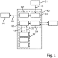
- the drawing shows a flowchart to illustrate a method according to the invention for engaging a parking lock of a motor vehicle.
- the single figure shows a flow chart to illustrate a method for engaging a parking lock of a motor vehicle having the parking lock, a service brake and a parking brake, which motor vehicle is designed, for example, as a motor vehicle, in particular as a passenger car.
- the motor vehicle also includes, for example, an electronic computing device, by means of which an electronic stability program for driving dynamics control is implemented, so that critical driving states can be counteracted actively and in particular automatically by means of the electronic stability program.
- the motor vehicle also includes, for example, at least one sensor device, by means of which at least one speed, in particular a rolling speed, of the motor vehicle characterizing measured variable is detected, for example, in a first step S1 of the method.
- the sensor device comprises, for example, at least one wheel speed sensor for each wheel of the motor vehicle, by means of which a respective speed, also referred to as wheel speed, of the respective wheel is detected.
- a respective speed at which the respective wheel rotates can be determined on the basis of the respective wheel speed. If the speed is 0, for example, then it can be detected that the motor vehicle is at a standstill.
- the sensor device comprises, for example, at least one shaft speed sensor, by means of which a speed, also referred to as shaft speed, of at least one shaft of the motor vehicle is detected.
- the shaft is, for example, a transmission shaft of a transmission of the motor vehicle.
- the shaft can be an output shaft for driving the motor vehicle trained motor.
- the engine is, for example, an internal combustion engine, in particular a reciprocating piston machine, or an electric motor, so that the motor vehicle is designed, for example, as a hybrid or electric vehicle.
- a speed at which the shaft rotates can be detected on the basis of the shaft speed. If the shaft speed or the speed at which the shaft rotates is 0, it can be assumed, for example, that the motor vehicle is at a standstill.
- the sensor device has at least one communication element, which can communicate, for example, at least indirectly with satellites of a satellite-based navigation system.
- a speed also referred to as the driving speed
- the driving speed at which the vehicle is moving, for example on the ground or relative to a subsurface
- the sensor device provides at least one signal, in particular an electrical signal, for example in the first step S1, which characterizes the detected or determined speed.
- the signal and thus the ascertained detected speed are supplied to a system or a module 12, for example, with the module 12 being implemented by the electronic computing device, for example.
- the module 12 can be used to park the motor vehicle securely in such a way that the motor vehicle can be designed to be particularly cost-effective and light-weight.
- the parking lock is engaged while using a braking device of the motor vehicle rolling away of the motor vehicle is at least restricted, in particular prevented.
- an additional braking device of the motor vehicle that is provided for this purpose and is different from the service brake, the parking lock and the parking brake is used as the braking device.
- the motor vehicle which is initially moving at a certain speed and is therefore moving relative to the ground, is braked or decelerated, in particular automatically by means of the electronic computing device, for example the motor vehicle using the electronic stability program is slowed down or delayed.
- the motor vehicle is braked to a standstill, for example.
- the electronic computing device or the electronic stability program makes a deceleration request, illustrated by an arrow 16, to a module 14, by means of which, for example, the motor vehicle is decelerated or braked and in particular is decelerated to a standstill.
- the module 14 is implemented, for example, by the electronic computing device.
- a third step S3 of the method it is determined or recognized that the speed of the motor vehicle falls below a definable threshold value or that the motor vehicle is at a standstill. For example, in the third step S3 it is thus reliably recognized that the motor vehicle is at a standstill. For example, it is recognized on the basis of said signal that the speed at which the motor vehicle is moving along the ground falls below the predefinable threshold value or that the motor vehicle is at a standstill. In the error-free operation, for example, based on the wheel speed sensors or recognized based on the wheel speeds that the motor vehicle is at a standstill or that the speed of the motor vehicle falls below the threshold value.
- a fourth step S4 of the method the standstill is maintained or rolling away of the motor vehicle is at least restricted. If, for example, in the second step S2 the motor vehicle is braked by means of the service brake and thus by means of a brake fluid pressure, also referred to as brake pressure, then, for example, in the fourth step S4 the motor vehicle is braked by means of the service brake and thus by means of a brake fluid pressure, also referred to as brake pressure
- brake pressure is locked in or maintained via valves of the electronic stability program until the parking brake, which is designed in particular as an electric parking brake, is closed and/or the parking lock is engaged.
- the motor vehicle in error-free operation, the motor vehicle is held stationary by means of the brake pressure while the parking lock is engaged and/or the parking brake is closed.
- a fifth step S5 of the method for example, the standstill of the motor vehicle is permanently secured.
- the hydraulic brake pressure is released or reduced, so that the closed parking brake and/or the engaged parking lock then secure the standstill and thus the motor vehicle against undesired rolling away.
- data is exchanged, illustrated by arrows 18 and 20, with modules 22, by means of which the standstill is secured, for example.
- the modules 22 are implemented, for example, by the electronic computing device and are used, for example, to control at least one actuator of the parking brake and/or at least one actuator of the parking lock, so that the parking brake or the parking lock is closed or closed, for example, by means of the respective actuator can be inserted.
- the arrow 18 illustrates, for example, a request to the modules 22, so that the parking brake is closed and/or the parking lock is engaged by means of the modules 22, for example. If this is successful, then, for example, there is feedback, illustrated by arrow 20, that the parking brake is closed or the parking lock is engaged.
- the parking brake has failed because, for example, the electronic stability program that controls the parking brake has failed.
- the motor vehicle is braked, in particular automatically, by the electronic computing device, via the aforementioned braking device, which is different from the service brake, from the parking brake and from the parking lock, and in particular is decelerated to a standstill, in particular during the parking lock is still open.
- the braking device comprises, for example, the aforementioned electric motor designed to drive the motor vehicle and/or a secondary braking system (SBS).
- the standstill of the motor vehicle or the fact that the speed of the motor vehicle falls below the threshold value is detected, for example via redundant wheel speed sensors connected to the secondary brake system and/or by the fact that a speed of the aforementioned motor, in particular an output shaft of the engine, is detected and/or that a transmission output speed of a transmission is detected.
- the standstill of the motor vehicle or the fact that the speed of the motor vehicle is below the threshold value can be detected using the speed of the motor vehicle determined by means of the satellite-supported navigation system.
- the standstill is maintained or the motor vehicle is secured against excessive rolling or rolling away by the braking device as a braking device, at least restricts the vehicle from rolling away.
- Restricting the rolling away of the motor vehicle can be understood to mean that rolling away or rolling of the motor vehicle is completely prevented, so that the motor vehicle does not move.
- restricting the rolling away can be understood to mean that the motor vehicle is permitted to move only slightly at a low speed.
- the rolling away of the motor vehicle can be at least restricted by the braking device in such a way that the braking device includes the aforementioned electric motor, by means of which at least one shaft of the motor vehicle is alternately rotated back and forth.
- the vehicle's rolling away is at least restricted while the parking lock is engaged, with the vehicle's rolling away being restricted at least until the parking lock is fully engaged.
- the braking device is switched off or deactivated in the fifth step S5 of the method after the parking lock has been engaged, whereby the standstill and thus parking of the motor vehicle can be permanently secured by means of the parking lock.
Landscapes
- Engineering & Computer Science (AREA)
- Mechanical Engineering (AREA)
- Transportation (AREA)
- General Engineering & Computer Science (AREA)
- Power Engineering (AREA)
- Regulating Braking Force (AREA)
- Braking Arrangements (AREA)
- Braking Systems And Boosters (AREA)
Description
- Die Erfindung betrifft ein Verfahren zum Einlegen einer Parksperre eines Kraftfahrzeugs gemäß dem Oberbegriff von Patentanspruch 1. Ferner betrifft die Erfindung ein Kraftfahrzeug mit den Merkmalen des Patentanspruchs 11.
- Ein solches Verfahren zum Einlegen einer Parksperre eines Kraftfahrzeugs sowie ein solches Kraftfahrzeug sind beispielsweise bereits aus der
US 2016 / 0 355 165 A1 beziehungsweise aus derWO 2015 / 128 082 A1 bekannt. Das beispielsweise als Kraftwagen, insbesondere als Personenkraftwagen, ausgebildete Kraftfahrzeug umfasst die Parksperre, eine Betriebsbremse und eine Parkbremse. Im Rahmen des Verfahrens ist es vorgesehen, dass die Parksperre eingelegt wird, während mittels einer Bremsvorrichtung des Kraftfahrzeugs ein Wegrollen des Kraftfahrzeugs zumindest eingeschränkt wird. - Des Weiteren offenbart die
DE 10 2009 023 498 B4 eine Parksperrenanordnung für ein Kraftfahrzeug. - Die
DE 10 2012 217 704 A1 zeigt ein Verfahren zum automatischen Bremsen eines Kraftfahrzeugs im Fall eines ein Bremsen durch die Betriebsbremsanlage tatsächlich oder potentiell beeinträchtigenden Fehlers. Das Fahrzeug weist ein elektronisch gesteuertes Automatikgetriebe mit Parksperre auf und befindet sich in Bewegung. Das Fahrzeug umfasst vorzugsweise ein Fahrerassistenzsystem, wobei sich der Fahrer außerhalb des fahrenden Fahrzeugs befindet, beispielsweise ein per Fernbedienung kontrollierbares Parkassistenzsystem. Gemäß dem Verfahren wird ein derartiger Fehlerfall erkannt, beispielsweise ein Fehler in Betriebsbremsanlage. In Abhängigkeit der Erkennung des Fehlerfalls wird veranlasst, dass die Parksperre bei Vorliegen des Fehlerfalls eingelegt wird, um das Fahrzeug zu bremsen, insbesondere in den Stillstand abzubremsen. - Die
DE 10 2004 047 100 B3 zeigt ein Kraftfahrzeug mit einer elektronisch ansteuerbaren Parksperre und mit einer elektronisch ansteuerbaren Feststellbremse, bei dem die Parksperre und die Feststellbremse unabhängig voneinander betätigbar sind, ist eine elektronische Steuereinheit vorgesehen, die derart ausgestaltet ist, dass bei Vorliegen einer Bedingung zur Aktivierung der Parksperre vor der Aktivierung der Parksperre zuerst die Feststellbremse aktivierbar ist. - Aufgabe der vorliegenden Erfindung ist es, ein Verfahren und ein Kraftfahrzeug der eingangs genannten Art zu schaffen, sodass das Gewicht und die Kosten des Kraftfahrzeugs besonders gering gehalten werden können.
- Diese Aufgabe wird erfindungsgemäß durch ein Verfahren mit den Merkmalen des Patentanspruchs 1, sowie durch ein Kraftfahrzeug mit den Merkmalen des Patentanspruchs 11 gelöst. Vorteilhafte Ausgestaltungen mit zweckmäßigen Weiterbildungen der Erfindung sind in den übrigen Ansprüchen angegeben.
- Ein erster Aspekt der Erfindung betrifft ein Verfahren zum Einlegen beziehungsweise Aktivieren einer Parksperre eines Kraftfahrzeugs, insbesondere eines Kraftwagens und vorzugsweise eines Personenkraftwagens. Das Kraftfahrzeug umfasst dabei die Parksperre, eine Betriebsbremse und eine Parkbremse. Die Betriebsbremse wird auch als Betriebsbremsanlage bezeichnet und dient dazu, das Kraftfahrzeug während eines normalen Betriebs zu verlangsamen sowie in seinen Stillstand zu bringen. Hierzu ist die Betriebsbremse beispielsweise von dem Fahrer des Kraftfahrzeugs, insbesondere per Fuß, betätigbar, indem der Fahrer beispielsweise mit seinem Fuß ein Bremspedal betätigt, insbesondere drückt. Die Parkbremse wird üblicherweise auch als Feststellbremse bezeichnet und dient im Gegensatz zu der Betriebsbremse üblicherweise nicht dazu, das Kraftfahrzeug während des normalen Betriebs zu verlangsamen und gegebenenfalls in den Stillstand abzubremsen, sondern dazu, das Kraftfahrzeug, insbesondere dessen Räder, dauerhaft zu blockieren und somit das Kraftfahrzeug in seinem Stillstand und somit gegen ein Wegrollen zu sichern. Insbesondere ist es vorgesehen, dass die Parkbremse als elektrische Parkbremse beziehungsweise elektrische Feststellbremse ausgebildet ist.
- Die Parksperre umfasst beispielsweise wenigstens eine Parkklinke, welche beispielsweise zumindest mittelbar bewegbar an einem Gehäuse, insbesondere eines Getriebes, des Kraftfahrzeugs gelagert und zwischen wenigstens einer Freigabestellung und wenigstens einer Sperrstellung relativ zu dem Gehäuse bewegbar, insbesondere verschwenkbar, ist. In der Sperrstellung greift beispielsweise die Parkklinke in eine korrespondierende Ausnehmung ein, welche beispielsweise an einer Welle, insbesondere an einer Getriebewelle des Getriebes, vorgesehen ist. Die Welle ist dabei beispielsweise zumindest mittelbar mit wenigstens einem Rad oder mit mehreren Rädern des Kraftfahrzeugs gekoppelt. Greift die Parkklinke in die korrespondierende Ausnehmung ein, so wird die Welle gegen eine Drehung relativ zu dem genannten Gehäuse gesichert, wodurch das Rad beziehungsweise die Räder gegen eine unerwünschte Drehung gesichert werden. In der Folge wird das Kraftfahrzeug gegen ein unerwünschtes Wegrollen, insbesondere formschlüssig, gesichert. Die Ausnehmung ist beispielsweise durch ein Parksperrenrad gebildet, welches drehfest mit der Welle verbunden oder einstückig mit der Welle ausgebildet sein kann.
- Unter dem Einlegen der Parksperre ist dabei insbesondere zu verstehen, dass beispielsweise die Parkklinke aus der Freigabestellung in die Sperrstellung bewegt wird. In der Freigabestellung ist die Parkklinke vollständig außerhalb der Ausnehmung angeordnet. Mit anderen Worten greift die Parcklinke in der Freigabestellung nicht in die Ausnehmung ein, sodass sich die Welle und in der Folge das Rad beziehungsweise die Räder drehen können. Bei dem Verfahren wird die Parksperre eingelegt, während mittels einer Bremsvorrichtung des Kraftfahrzeugs ein Wegrollen des Kraftfahrzeugs zumindest eingeschränkt wird.
- Um nun das Gewicht und die Kosten des Kraftfahrzeugs besonders gering halten zu können, ist es erfindungsgemäß vorgesehen, dass als die Bremsvorrichtung, mittels welcher das Wegrollen des Kraftfahrzeugs zumindest eingeschränkt wird, während die Parksperre eingelegt wird, eine von der Betriebsbremse und von der Parkbremse unterschiedliche, zusätzlich dazu vorgesehene Bremsvorrichtung des Kraftfahrzeugs verwendet wird.
- Um die Teileanzahl und somit das Gewicht und die Kosten des Kraftfahrzeugs besonders gering halten zu können, ist es erfindungsgemäß vorgesehen, dass die Bremsvorrichtung ein sekundäres, mittels eines Fluids, insbesondere mittels einer Flüssigkeit, betätigbares und einen elektronischen Bremskraftverstärker (eKBV) umfassendes Bremssystem aufweist, mittels welchem das Wegrollen des Kraftfahrzeugs derart zumindest eingeschränkt, insbesondere unterbunden, wird, dass der elektronische Bremskraftverstärker unabhängig von einer durch eine Person wie beispielsweise dem Fahrer des Kraftfahrzeugs bewirkten Betätigung des elektronischen Bremskraftverstärkers einen Druck des Fluids zum Betätigen des Bremsvorrichtung bewirkt. Das sekundäre Bremssystem (SBS) ist zusätzlich zur eigentlichen Betriebsbremse vorgesehen und somit ein redundantes Bremssystem, welches beispielsweise zum Einsatz kommt, um ein besonders sicheres automatisches beziehungsweise autonomes Fahren des Kraftfahrzeugs zu realisieren. Somit wird auch bei dieser Ausführungsform der Erfindung auf eine ohnehin vorgesehene Komponente in Form des sekundären Bremssystems zurückgegriffen, um das Wegrollen des Kraftfahrzeugs auf kosten- und gewichtsgünstige Weise zu vermeiden. In der Folge kann die Parksperre lastarm oder zumindest nahezu lastfrei eingelegt werden, sodass die Parksperre selbst gewichts- und kostengünstig ausgestaltet werden kann.
- Während bei herkömmlichen Verfahren und Kraftfahrzeugen lediglich ein fehlerfreier Normalzustand des Kraftfahrzeugs betrachtet wird, berücksichtigt das erfindungsgemäße Verfahren auch einen etwaigen Fehler beziehungsweise Fehlerzustand des Kraftfahrzeugs, wobei im Rahmen des Fehlers beispielsweise die insbesondere als elektronische Parkbremse ausgebildete Parkbremse und/oder die Betriebsbremse ausfällt und somit nicht zur Verfügung steht beziehungsweise nicht genutzt werden kann, um, insbesondere während die Parksperre eingelegt wird, das Wegrollen des Kraftfahrzeugs zumindest einzuschränken. Da bei herkömmlichen Verfahren beziehungsweise Kraftfahrzeugen ein solcher Fehlerfall nicht berücksichtigt wird, muss die Parksperre, insbesondere die Parkklinke, bei herkömmlichen Kraftfahrzeugen besonders massiv und somit gewichts- und kostenintensiv ausgelegt werden, da es beispielsweise bei Ausfall der Betriebsbremse und/oder der Parkbremse zu einem Zustand kommen kann, in welchem das Kraftfahrzeug rollt und sich somit mit einer geringen Geschwindigkeit bewegt, während die Parksperre eingelegt wird. Hierbei dreht sich zum Beispiel das zuvor genannte Parksperrenrad, während die Parkklinke in die Ausnehmung bewegt wird, was zu sehr hohen Belastungen der Parksperre führen kann. Damit bei herkömmlichen Kraftfahrzeugen die Parksperre auch im Fehlerfall die genannten hohen Belastungen schadfrei ertragen kann, muss die Parksperre üblicherweise besonders massiv und somit gewichts- und kostenintensiv ausgelegt werden.
- Dies kann nun jedoch mittels des erfindungsgemäßen Verfahrens vermieden werden, da auch bei Ausfall der Betriebsbremse und/oder der Parkbremse eine übermäßige Rollbewegung und somit eine übermäßige Geschwindigkeit des Kraftfahrzeugs vermieden werden kann, während die Parksperre eingelegt wird. Hierzu wird das Wegrollen des Kraftfahrzeugs mittels der genannten Bremsvorrichtung zumindest eingeschränkt, insbesondere unterbunden, sodass sich das Kraftfahrzeug nicht oder nicht übermäßig bewegt, während die Parksperre eingelegt wird. In der Folge kann die Parksperre besonders filigran und somit gewichts- und kostengünstig ausgelegt werden, sodass das Gewicht und die Kosten des Kraftfahrzeugs insgesamt in einem besonders geringen Rahmen gehalten werden können.
- Insbesondere liegt der Erfindung die folgende Erkenntnis zugrunde: Über die vorzugsweise als hydraulische Betriebsbremse ausgebildete Betriebsbremse wird das Kraftfahrzeug, insbesondere von dessen Fahrer, üblicherweise in den Stillstand gebremst und anschließend auch im Stillstand gehalten. Bei heutigen, insbesondere als Automatikgetrieben ausgebildeten Getrieben wird dann das Kraftfahrzeug über die auch als Getriebesperre bezeichnete Parksperre in Kombination mit der Parkbremse gesichert, welche beispielsweise als elektrische Parkbremse (EPB) ausgebildet ist. Die Betriebsbremse, die Parksperre und die Parkbremse sind Systeme, welche herkömmlicherweise zumindest weitgehend unabhängig voneinander agieren. Dies führt dazu, dass jedes System für sich möglichst sicher ausgebildet wird. Dabei ist üblicherweise insbesondere die Parksperre, insbesondere die Parkklinke, so ausgebildet, dass im Normalfall die Parksperre nur dann eingelegt wird, wenn beispielsweise ein Parkhebel in eine Parkstellung gebracht wird oder der Fahrer das Kraftfahrzeug verlässt, während sich der Parkhebel in einer Vorwärtsfahr- oder Rückfahrstufe befindet. Befindet sich das Kraftfahrzeug zu diesem Zeitpunkt noch in Bewegung, so ist die Parksperre üblicherweise so ausgebildet, dass die Parkklinke nicht in Eingriff mit der Ausnehmung kommt und über diese beziehungsweise über das Parksperrenrad ratscht. Die Parksperre ist somit eigensicher ausgebildet. Ein Blockieren durch die fälschlicherweise einfahrende beziehungsweise eingelegte Parksperre wird so verhindert.
- Mit zunehmender Elektrifizierung von Kraftfahrzeugen können für die Parksperre herkömmliche Konzepte nicht mehr übernommen werden, wobei insbesondere bistationäre Aktoren entwickelt werden, mittels welchen die Parksperre, insbesondere die Parkklinke, aktiv eingelegt und ausgelegt werden kann.
- Durch die massive Ausgestaltung der Parksperre weist diese eine aufwändige und somit kosten- und gewichtsintensive Konstruktion auf. Hierbei sind Bauteile vorzusehen, die das beschriebene Ratschen ermöglichen. Ferner sind herkömmlicherweise Lastfälle zu berücksichtigen, in denen die Parkklinke einfällt beziehungsweise eingelegt wird, während sich das Kraftfahrzeug noch bewegt. Hierbei kommt es zu einer hohen, auf die Parksperre wirkenden Belastung, welche bei einer Konstruktion der Parksperre zu berücksichtigen sind. Zum Auslegen der Parksperre, das heißt beispielsweise zum Bewegen der Parkklinke aus der Sperrstellung in die Freigabestellung, ist dabei ferner eine erhöhte Kraft, insbesondere Zugkraft, erforderlich, welche beispielsweise von einem Aktor auf die Parkklinke aufzubringen ist, um diese auszulegen, da die Parksperre unter Last steht beziehungsweise verspannt ist. Ferner soll ein selbständiges Auslegen der Parksperre verhindert werden. Dies erfordert üblicherweise einen Hinterschnitt an der Parkklinke und in der Ausnehmung. Daraus resultiert beispielsweise die Verwendung eines eigenen Zahnrads für die Parksperre, wobei das Zahnrad beispielsweise das zuvor genannte Parksperrenrad ist. Als dies führt dazu, dass herkömmliche Parksperren inklusive des Aktors bauraum-, kosten- und gewichtsintensiv sind.
- Diese Probleme beziehungsweise Nachteile können nun mittels des erfindungsgemäßen Verfahrens vermieden werden, da im Rahmen des erfindungsgemäßen Verfahrens auf die von der Betriebsbremse, von der Parkbremse und von der Parksperre unterschiedliche Bremsvorrichtung zurückgegriffen wird, um das Kraftfahrzeug in seinem Stillstand zu sichern beziehungsweise das Wegrollen des Kraftfahrzeugs zumindest einzuschränken, sodass - während die Parksperre eingelegt wird - das Fahrzeug steht beziehungsweise eine übermäßige Bewegung des Fahrzeugs vermieden wird. Insbesondere wird das Wegrollen des Kraftfahrzeugs solange zumindest eingeschränkt, bis die Parksperre, insbesondere die Parkklinke, vollständig eingefahren ist.
- Mittels des erfindungsgemäßen Verfahrens kann ausgeschlossen werden, dass die Parksperre eingelegt wird, wenn sich das Kraftfahrzeug übermäßig bewegt. Somit können herkömmlicherweise vorgesehene Sicherheitsmaßnahmen entfallen, sodass die Parksperre, insbesondere die Parkklinke, filigran und somit kosten- und gewichtsgünstig ausgelegt werden kann. Insbesondere ist es möglich, die Parksperre, insbesondere in einem Normalfall, lastfrei ein- und zumindest nahezu lastfrei auszulegen, sodass die Parksperre besonders gewichts- und kostengünstig dimensioniert werden kann. Ferner ist es beispielsweise möglich, zur Realisierung der genannten Ausnehmung kein zusätzliches, separates Parksperrenrad beziehungsweise Zahnrad zu verwenden, sondern die Ausnehmung kann beispielsweise durch ein ohnehin vorgesehenes Zahnrad oder durch eine ohnehin vorgesehene Welle gebildet werden. Ferner ist es beispielsweise möglich, anstelle der auch als Klinke bezeichneten Parkklinke einen bauraum-, gewichts- und kostengünstigen Stift zu verwenden, welcher beispielsweise zwischen der Freigabestellung und der Sperrstellung translatorisch, insbesondere relativ zu dem Gehäuse, bewegt werden kann. Ferner kann beispielsweise dann, wenn das Getriebe als selbsthemmendes Getriebe ausgebildet ist, der zuvor genannte Hinterschnitt vermieden werden, sodass die Parksperre beziehungsweise das Kraftfahrzeug insgesamt besonders kostengünstig ausgestaltet werden kann.
- Wird beispielsweise zum Bewegen der Parkklinke beziehungsweise des Stifts zwischen der Freigabestellung und der Sperrstellung ein Aktor, insbesondere ein elektrisch betreibbarer Aktor, verwendet, so kann dieser dadurch, dass die Parkklinke beziehungsweise der Stift besonders lastarm oder gar lastfrei ein- und/oder ausgelegt werden kann, besonders bauraum, gewichts- und kostengünstig ausgelegt werden. Außerdem kann die Parcklinke beziehungsweise der Stift beziehungsweise die Parksperre insgesamt besonders vorteilhaft verbaut beziehungsweise angeordnet werden, wobei die Parksperre beispielsweise in einem Getriebe, einem Differential, direkt an einem zum Antreiben des Kraftfahrzeugs ausgebildeten Motor oder an einer Achse angeordnet werden kann.
- Um die Teileanzahl und somit das Gewicht und die Kosten des Kraftfahrzeugs besonders gering halten zu können, ist es in vorteilhafter Ausgestaltung der Erfindung vorgesehen, dass die Bremsvorrichtung wenigstens einen zum Antreiben des Kraftfahrzeugs ausgebildeten Elektromotor umfasst, mittels welchem das Wegrollen des Kraftfahrzeugs derart zumindest eingeschränkt wird, dass mittels des Elektromotors wenigstens eine Welle des Kraftfahrzeugs mehrmals abwechselnd in eine erste Drehrichtung und in eine der ersten Drehrichtung entgegengesetzte zweite Drehrichtung bewegt wird. Mit anderen Worten wird beispielsweise die Welle mittels des Elektromotors, insbesondere mit einer besonders hohen Frequenz, abwechselnd hin- und her bewegt, um dadurch beispielsweise ein Wegrollen beziehungsweise ein übermäßig schnelles Rollen des Kraftfahrzeugs zu vermeiden.
- Insgesamt ist erkennbar, dass beispielsweise mittels des Elektromotors wenigstens eine Bewegung der Welle bewirkt wird, um beispielsweise ein Wegrollen beziehungsweise ein übermäßig schnelles Rollen des Kraftfahrzeugs zu vermeiden. Die mittels des Elektromotors bewirkte Bewegung der Welle ist beispielsweise von dem Elektromotor, insbesondere von dessen Art beziehungsweise Ausführung, abhängig. Beispielsweise kann als der Elektromotor ein Elektromotor verwendet werden, der ein Haltemoment direkt stellen kann oder stellt und auf die Welle ausübt, sodass beispielsweise nicht durch schnelles Hin-und Herdrehen, sondern dadurch einen quai-statischer Zustand erreicht oder bewirkt wird, dass die Welle mittels des Elektromotors gehalten und somit gegen eine Drehung gesichert wird. Hierzu übt der Elektromotor das Haltemoment als ein Drehmoment auf die Welle aus.
- Die Bremsvorrichtung wird dabei den ohnehin vorgesehenen Elektromotor des beispielsweise als Hybrid- oder Elektrofahrzeug ausgebildeten und mittels des Elektromotors antreibbaren Kraftfahrzeugs. Das erfindungsgemäße Verfahren greift somit auf eine, insbesondere ohnehin vorgesehene, Elektrifizierung des Kraftfahrzeugs zurück und nutzt eine ohnehin vorgesehene, von der Parkbremse, von der Parksperre und von der Betriebsbremse unterschiedliche Komponente in Form des Elektromotors, um das Wegrollen zumindest einzuschränken. Hierdurch kann auf einfache, gewichts- und kostengünstige Weise realisiert werden, dass das Kraftfahrzeug steht und stehenbleibt beziehungsweise sich nicht übermäßig bewegt, während die Parksperre eingelegt wird.
- Um beim Einlegen der Parksperre auf die Parksperre wirkende Lasten besonders gering halten und in der Folge die Parksperre besonders gewichts- und kostengünstig ausgestalten zu können, ist es bei einer weiteren Ausführungsform der Erfindung vorgesehen, dass mittels wenigstens einer Sensoreinrichtung, insbesondere des Kraftfahrzeugs, wenigstens eine eine Rollgeschwindigkeit des Kraftfahrzeugs charakterisierende Messgröße erfasst wird, wobei die Parksperre in Abhängigkeit von der erfassten Messgröße eingelegt wird. Die Messgröße ist eine Information, welche beim Einlegen der Parksperre miteinbezogen wird, um beispielsweise anhand der Messgröße sicher identifizieren zu können, ob eine übermäßige Geschwindigkeit, insbesondere Rollgeschwindigkeit, des Kraftfahrzeugs vorliegt oder nicht. Dadurch kann sichergestellt werden, dass die Parksperre dann und insbesondere nur dann eingelegt wird, wenn das Einlegen der Parksperre ohne auf die parksperrende Last oder nur unter geringster Last erfolgt. Ferner wird beispielsweise eine Logik verwendet, welche sicherstellt, dass das Auslegen der Parksperre nicht oder nur unter geringster Last erfolgt, beispielsweise derart, dass mittels des Elektromotors die genannte Ausnehmung beziehungsweise die Getriebewelle derart gedreht wird, um die zunächst eingelegte Parksperre zu entspannen. In der Folge kann die Parksperre lastfrei oder besonders lastarm ausgelegt werden, was sich wiederum auf die von dem Aktor, insbesondere zum Bewegen der Parksperrenklinke, benötigte Kraft auswirkt. Der Aktor muss somit geringere Kräfte stellen und kann so kleiner und günstiger dimensioniert werden. Vorstellbar ist auch ein Technologiewechsel weg vom Getriebemotor, der hohe Kräfte stellen kann, hin zu einem Magneten, der deutlich geringer Kraftniveaus darstellen kann.
- In weiterer Ausgestaltung der Erfindung ist es vorgesehen, dass die Parksperre eingelegt wird, wenn die Messgröße einen vorgebbaren Schwellenwert unterschreitet. Hierdurch kann sichergestellt werden, dass die Parksperre dann und vorzugsweise nur dann eingelegt wird, wenn das Kraftfahrzeug nicht oder mit einer nur sehr geringen Geschwindigkeit von beispielsweise weniger als zwei Kilometern pro Stunde rollt.
- Als besonders vorteilhaft hat es gezeigt, wenn die Messgröße eine Drehzahl zumindest eines Rads des Kraftfahrzeugs und die Sensoreinrichtung wenigstens einen Raddrehzahlsensor umfasst, mittels welchem die Drehzahl des Rads erfasst wird, wobei die Parksperre in Abhängigkeit von der erfassten Drehzahl des Rads eingelegt und insbesondere dann eingelegt wird, wenn die erfasste Drehzahl des Rads den vorgebbaren Schwellenwert unterschreitet.
- Eine weitere Ausführungsform zeichnet sich dadurch aus, dass die Messgröße eine Drehzahl einer Welle des Kraftfahrzeugs, insbesondere des zum Antreiben des Kraftfahrzeugs ausgebildeten Motors des Kraftfahrzeugs, und die Sensoreinrichtung wenigstens einen Wellendrehzahlsensor umfasst, mittels welchem die Drehzahl der Welle erfasst wird, wobei die Parksperre in Abhängigkeit von der erfassten Drehzahl der Welle eingelegt und beispielsweise dann eingelegt wird, wenn die erfasste Drehzahl der Welle den vorgebbaren Schwellenwert unterschreitet. Somit werden beispielsweise Informationen wie die Drehzahl des Motors, wenigstens eine Drehzahl an einem Gang eines Getriebes des Kraftfahrzeugs, einfache oder redundante Raddrehzahlsensoren und/oder weitere, insbesondere die Rollgeschwindigkeit des Kraftfahrzeugs charakterisierende Informationen miteinbezogen, um sicherzustellen, dass die Parksperre dann und vorzugsweise nur dann eingelegt wird, wenn ein Rollen beziehungsweise Wegrollen des Kraftfahrzeugs mit einer übermäßigen Geschwindigkeit unterbleibt.
- Um sicherzustellen, dass die Parksperre dann und nur dann eingelegt wird, wenn ein Rollen des Kraftfahrzeugs mit einer übermäßigen Geschwindigkeit unterbleibt, sodass in der Folge die Parksperre und somit das Kraftfahrzeug insgesamt besonders gewichts- und kostengünstig ausgestaltet werden kann, ist es in weiterer Ausgestaltung der Erfindung vorgesehen, dass anhand eines satellitengestützten Navigationssystems eine Geschwindigkeit des Kraftfahrzeugs ermittelt wird, wobei die Parksperre in Abhängigkeit von der ermittelten Geschwindigkeit eingelegt wird. Das satellitengestützte Navigationssystem ist beispielsweise GPS (Global Positioning System), wobei die Parksperre beispielsweise eingelegt wird, wenn die ermittelte Geschwindigkeit des Kraftfahrzeugs den vorgebbaren Schwellenwert unterschreitet.
- In weiterer Ausgestaltung der Erfindung wird nach dem Einlegen der Parksperre die Bremsvorrichtung deaktiviert, sodass ein besonders energiearmer und somit kostengünstiger Betrieb realisierbar ist.
- Um auf besonders einfache und kostengünstige Weise einen besonders vorteilhaften Betrieb zu realisieren, ist es bei einer weiteren Ausführungsform der Erfindung vorgesehen, dass das Wegrollen des Kraftfahrzeugs mittels der Bremsvorrichtung automatisch zumindest eingeschränkt, insbesondere unterbunden wird, indem eine elektronische Recheneinrichtung des Kraftfahrzeugs die Bremsvorrichtung ansteuert. Mit anderen Worten wird die Bremsvorrichtung mittels der elektronischen Recheneinrichtung gesteuert oder geregelt, um dadurch das Wegrollen des Kraftfahrzeugs zumindest einzuschränken, während die Parksperre eingelegt wird.
- Um einen besonders sicheren Betrieb auf gewichts- und kostengünstige Weise zu erreichen, ist es bei einer weiteren Ausführungsform der Erfindung vorgesehen, dass das zunächst fahrende und somit rollende Kraftfahrzeug mittels der elektronischen Recheneinrichtung des Kraftfahrzeugs über die Bremsvorrichtung automatisch abgebremst wird, indem die Recheneinrichtung die Bremsvorrichtung ansteuert, woraufhin mittels der Bremsvorrichtung das Wegrollen des Kraftfahrzeugs zumindest eingeschränkt wird. Hierdurch ist beispielsweise ein autonomer beziehungsweise automatischer oder aber ein teil-autonomer beziehungsweise teil-automatischer Betrieb des Kraftfahrzeugs realisierbar, insbesondere unter Nutzung bereits vorhandener Komponenten, sodass die Teileanzahl, das Gewicht und die Kosten des Kraftfahrzeugs in einem besonders geringen Rahmen gehalten werden können.
- Ein zweiter Aspekt der Erfindung betrifft ein Kraftfahrzeug, insbesondere einen Kraftwagen und vorzugsweise einen Personenkraftwagen. Das Kraftfahrzeug umfasst eine Parksperre, eine Betriebsbremse und eine Parkbremse.
- Um nun das Kraftfahrzeug besonders gewichts- und kostengünstig ausgestalten zu können, ist erfindungsgemäß eine von der Betriebsbremse, von der Parkbremse und von der Parksperre unterschiedliche, zusätzlich dazu vorgesehene Bremseinrichtung vorgesehen, welche dazu ausgebildet ist, während eines Einlegens der Parksperre ein Wegrollen des Kraftfahrzeugs zumindest einzuschränken, insbesondere zu unterbinden.
- Erfindungsgemäß ist vorgesehen, dass die Bremsvorrichtung ein sekundäres, mittels eines Fluids, insbesondere mittels einer Flüssigkeit, betätigbares und einen elektronischen Bremskraftverstärker (eKBV) umfassendes Bremssystem aufweist, mittels welchem das Wegrollen des Kraftfahrzeugs derart zumindest eingeschränkt, insbesondere unterbunden, wird, dass der elektronische Bremskraftverstärker unabhängig von einer durch eine Person wie beispielsweise dem Fahrer des Kraftfahrzeugs bewirkten Betätigung des elektronischen Bremskraftverstärkers einen Druck des Fluids zum Betätigen des Bremsvorrichtung bewirkt. Das sekundäre Bremssystem (SBS) ist zusätzlich zur eigentlichen Betriebsbremse vorgesehen und somit ein redundantes Bremssystem, welches beispielsweise zum Einsatz kommt, um ein besonders sicheres automatisches beziehungsweise autonomes Fahren des Kraftfahrzeugs zu realisieren. Somit wird auch bei dieser Ausführungsform der Erfindung auf eine ohnehin vorgesehene Komponente in Form des sekundären Bremssystems zurückgegriffen, um das Wegrollen des Kraftfahrzeugs auf kosten- und gewichtsgünstige Weise zu vermeiden. In der Folge kann die Parksperre lastarm oder zumindest nahezu lastfrei eingelegt werden, sodass die Parksperre selbst gewichts- und kostengünstig ausgestaltet werden kann.
- Somit ist das erfindungsgemäße Kraftfahrzeug beispielsweise zum Durchführen eines erfindungsgemäßen Verfahrens ausgebildet. Vorteile und vorteilhafte Ausgestaltungen des ersten Aspekts der Erfindung sind als Vorteile und vorteilhafte Ausgestaltungen des zweiten Aspekt der Erfindung anzusehen und umgekehrt.
- Weitere Vorteile, Merkmale und Einzelheiten der Erfindung ergeben sich aus der nachfolgenden Beschreibung eines bevorzugten Ausführungsbeispiels sowie anhand der Zeichnung. Die vorstehend in der Beschreibung genannten Merkmale und Merkmalskombinationen sowie die nachfolgend in der Figurenbeschreibung genannten und/oder in der einzigen Figur alleine gezeigten Merkmale und Merkmalskombinationen sind nicht nur in der jeweils angegebenen Kombination, sondern auch in anderen Kombinationen oder in Alleinstellung verwendbar, ohne den Rahmen der Erfindung zu verlassen.
- Die Zeichnung zeigt in der einzigen Figur ein Flussdiagramm zum Veranschaulichen eines erfindungsgemäßen Verfahrens zum Einlegen einer Parksperre eines Kraftfahrzeugs.
- Die einzige Figur zeigt ein Flussdiagram zum Veranschaulichen eines Verfahrens zum Einlegen einer Parksperre eines die Parksperre, eine Betriebsbremse und eine Parkbremse aufweisenden Kraftfahrzeugs, das beispielsweise als Kraftwagen, insbesondere als Personenkraftwagen, ausgebildet ist. Das Kraftfahrzeug umfasst ferner beispielsweise eine elektronische Recheneinrichtung, mittels welcher ein elektronisches Stabilitätsprogramm zur Fahrdynamikregelung realisiert ist, sodass mittels des elektronischen Stabilitätsprogramms kritischen Fahrzuständen aktiv und insbesondere automatisch entgegengewirkt werden kann.
- Das Kraftfahrzeug umfasst ferner beispielsweise wenigstens eine Sensoreinrichtung, mittels welcher beispielsweise bei einem ersten Schritt S1 des Verfahrens wenigstens eine Geschwindigkeit, insbesondere eine Rollgeschwindigkeit, des Kraftfahrzeugs charakterisierende Messgröße erfasst wird. Die Sensoreinrichtung umfasst beispielsweise je Rad des Kraftfahrzeugs wenigstens einen Raddrehzahlsensor, mittels welchem eine jeweilige, auch als Raddrehzahl bezeichnete Drehzahl des jeweiligen Rads erfasst wird. Anhand der jeweiligen Raddrehzahl kann eine jeweilige Geschwindigkeit ermittelt werden, mit welcher sich das jeweilige Rad dreht. Beträgt die Geschwindigkeit beispielsweise 0, so kann dadurch erfasst werden, dass sich das Kraftfahrzeug in seinem Stillstand befindet. Alternativ oder zusätzlich umfasst die Sensoreinrichtung beispielsweise wenigstens einen Wellendrehzahlsensor, mittels welchem eine auch als Wellendrehzahl bezeichnete Drehzahl wenigstens einer Welle des Kraftfahrzeugs erfasst wird. Die Welle ist beispielsweise eine Getriebewelle eines Getriebes des Kraftfahrzeugs. Ferner kann die Welle eine Abtriebswelle eines zum Antreiben des Kraftfahrzeugs ausgebildeten Motors sein. Der Motor ist beispielsweise ein Verbrennungsmotor, insbesondere eine Hubkolbenmaschine, oder aber ein Elektromotor, sodass das Kraftfahrzeug beispielsweise als Hybrid- oder Elektrofahrzeug ausgebildet ist. Anhand der Wellendrehzahl kann eine Geschwindigkeit erfasst werden, mit welcher sich die Welle dreht. Beträgt die Wellendrehzahl beziehungsweise die Geschwindigkeit, mit welcher sich die Welle dreht, 0, so kann beispielsweise davon ausgegangen werden, dass sich das Kraftfahrzeug in seinem Stillstand befindet.
- Ferner ist es denkbar, dass die Sensoreinrichtung wenigstens ein Kommunikationselement aufweist, welches beispielsweise zumindest mittelbar mit Satelliten eines satellitengestützten Navigationssystems kommunizieren kann. Auf diese Weise ist es beispielsweise mittels des Kommunikationselements und mittels des satellitengestützten Navigationssystems möglich, eine auch als Fahrgeschwindigkeit bezeichnete Geschwindigkeit, mit welcher sich das Fahrzeug beispielsweise auf der Erde beziehungsweise relativ zu einem Untergrund bewegt, zu ermitteln, sodass anhand der Fahrgeschwindigkeit ermittelt werden kann, ob sich das Kraftfahrzeug in seinem Stillstand befindet oder relativ zu dem Untergrund beziehungsweise entlang des Untergrunds bewegt.
- Wie in der Figur durch einen gestrichelten Pfeil 10 veranschaulicht ist, stellt die Sensoreinrichtung beispielsweise bei dem ersten Schritt S1 wenigstens ein, insbesondere elektrisches, Signal bereit, welches die erfasste beziehungsweise ermittelte Geschwindigkeit charakterisiert. Das Signal und somit die ermittelte erfasste Geschwindigkeit werden beispielsweise einem System oder einem Modul 12 zugeführt, wobei das Modul 12 beispielsweise durch die elektronische Recheneinrichtung realisiert ist. Mittels des Moduls 12 kann ein sicheres Parken des Kraftfahrzeugs derart realisiert werden, dass das Kraftfahrzeug besonders kosten- und gewichtsgünstig ausgestaltet werden kann.
- Wie im Folgenden noch genauer erläutert wird, wird bei dem Verfahren die Parksperre eingelegt, während mittels einer Bremsvorrichtung des Kraftfahrzeugs ein Wegrollen des Kraftfahrzeugs zumindest eingeschränkt, insbesondere unterbunden, wird. Um dabei das Gewicht und die Kosten des Kraftfahrzeugs besonders gering halten zu können, wird als die Bremsvorrichtung ein von der Betriebsbremse, von der Parksperre und von der Parkbremse unterschiedliche, zusätzliche dazu vorgesehene Bremsvorrichtung des Kraftfahrzeugs verwendet.
- Im Folgenden wird beispielsweise ein fehlerfreier Betrieb des Kraftfahrzeugs beschrieben. In dem fehlerfreien Betrieb wird bei einem zweiten Schritt S2 des Verfahrens das sich beispielsweise zunächst mit einer gewissen Geschwindigkeit bewegende und sich somit relativ zu dem Untergrund fahrbewegende Kraftfahrzeug, insbesondere automatisch mittels der elektronischen Recheneinrichtung, abgebremst beziehungsweise verzögert, wobei beispielsweise das Kraftfahrzeug mittels des elektronischen Stabilitätsprogramms abgebremst beziehungsweise verzögert wird. Insbesondere wird das Kraftfahrzeug bei dem zweiten Schritt S2 beispielsweise in seinen Stillstand gebremst. Hierzu stellt beispielsweise die elektronische Recheneinrichtung beziehungsweise das elektronische Stabilitätsprogramm eine durch einen Pfeil 16 veranschaulichte Verzögerungsanforderung an ein Modul 14, mittels welchem beispielsweise das Kraftfahrzeug verzögert beziehungsweise abgebremst und dabei insbesondere in den Stillstand verzögert wird. Das Modul 14 ist beispielsweise durch die elektronische Recheneinrichtung realisiert.
- Bei einem dritten Schritt S3 des Verfahrens wird ermittelt beziehungsweise erkannt, dass die Geschwindigkeit des Kraftfahrzeugs einen vorgebbaren Schwellenwert unterschreitet beziehungsweise dass sich das Kraftfahrzeug in dem Stillstand befindet. Beispielsweise wird somit bei dem dritten Schritt S3 sicher erkannt, dass sich das Kraftfahrzeug in seinem Stillstand befindet. Beispielsweise wird anhand des genannten Signals erkannt, dass die Geschwindigkeit, mit der sich das Kraftfahrzeug entlang des Untergrunds bewegt, den vorgebbaren Schwellenwert unterschreitet beziehungsweise dass sich das Kraftfahrzeug in seinem Stillstand befindet. Bei dem fehlerfreien Betrieb wird beispielsweise anhand der Raddrehzahlsensoren beziehungsweise anhand der Raddrehzahlen erkannt, dass sich das Kraftfahrzeug im Stillstand befindet beziehungsweise dass die Geschwindigkeit des Kraftfahrzeugs den Schwellenwert unterschreitet.
- Bei einem vierten Schritt S4 des Verfahrens wird der Stillstand beibehalten beziehungsweise ein Wegrollen des Kraftfahrzeugs wird zumindest eingeschränkt. Wird beispielsweise bei dem zweiten Schritt S2 das Kraftfahrzeug mittels der Betriebsbremse und somit mittels eines auch als Bremsdruck bezeichneten Drucks einer Bremsflüssigkeit abgebremst, so wird beispielsweise bei dem vierten Schritt S4 das Kraftfahrzeug mittels der Betriebsbremse und somit mittels eines auch als Bremsdruck bezeichneten Drucks einer Bremsflüssigkeit abgebremst, und so wird beispielsweise bei dem vierten Schritt S4 über Ventile des elektronischen Stabilitätsprogramms der Bremsdruck so lange eingesperrt beziehungsweise gehalten, bis die insbesondere als elektrische Parkbremse ausgebildete Parkbremse geschlossen ist und/oder die Parksperre eingelegt ist. Mit anderen Worten wird bei dem vierten Schritt S4 in dem fehlerfreien Betrieb das Kraftfahrzeug mittels des Bremsdrucks im Stillstand gehalten, während die Parksperre eingelegt und/oder die Parkbremse geschlossen wird.
- Bei einem fünften Schritt S5 des Verfahrens wird beispielsweise der Stillstand des Kraftfahrzeugs dauerhaft gesichert. Hierzu wird beispielsweise bei dem fünften Schritt S5 des Verfahren in dem fehlerfreien Betrieb der hydraulische Bremsdruck abgelassen beziehungsweise reduziert, sodass dann die geschlossene Parkbremse und/oder die eingelegte Parksperre den Stillstand und somit das Kraftfahrzeug gegen ein unerwünschtes Wegrollen sichern.
- Hierzu erfolgt beispielsweise ein durch Pfeile 18 und 20 veranschaulichter Datenaustausch mit Modulen 22, mittels welchen beispielsweise der Stillstand gesichert wird. Die Module 22 sind beispielsweise durch die elektronische Recheneinrichtung realisiert und werden beispielsweise genutzt, um wenigstens einen Aktor der Parkbremse und/oder wenigstens einen Aktor der Parksperre anzusteuern, sodass beispielsweise mittels des jeweiligen Aktors die Parkbremse beziehungsweise die Parksperre geschlossen beziehungsweise eingelegt werden kann. Durch den Pfeil 18 ist beispielsweise eine Anforderung an die Module 22 veranschaulicht, sodass mittels der Module 22 beispielsweise die Parkbremse geschlossen und/oder die Parksperre eingelegt wird. Ist dies erfolgreich, so erfolgt beispielsweise eine durch den Pfeil 20 veranschaulichte Rückmeldung, dass die Parkbremse geschlossen beziehungsweise die Parksperre eingelegt ist.
- Im Folgenden wird ein Fehler beziehungsweise ein Fehlerfall des Kraftfahrzeugs beschrieben. In diesem Fehlerfall ist beispielsweise die Parkbremse ausgefallen, da beispielsweise das elektronische Stabilitätsprogramm, welches die Parkbremse ansteuert, ausgefallen ist. In dem Fehlerfall wird beispielsweise bei dem zweiten Schritt S2 das Kraftfahrzeug, insbesondere automatisch, von der elektronischen Recheneinrichtung, über die zuvor genannte, von der Betriebsbremse, von der Parkbremse und von der Parksperre unterschiedliche Bremsvorrichtung abgebremst und dabei insbesondere in den Stillstand verzögert, insbesondere während die Parksperre noch ausgelegt ist. Hierzu umfasst die Bremsvorrichtung beispielsweise den zuvor genannten, zum Antreiben des Kraftfahrzeugs ausgebildeten Elektromotor und/oder ein sekundäres Bremssystem (SBS). In dem Fehlerfall wird bei dem dritten Schritt S3 der Stillstand des Kraftfahrzeugs beziehungsweise der Umstand, dass die Geschwindigkeit des Kraftfahrzeugs den Schwellenwert unterschreitet, beispielsweise über redundante, an das sekundäre Bremssystem angeschlossene Raddrehzahlsensoren und/oder dadurch erkannt, dass eine Drehzahl des zuvor genannten Motors, insbesondere eine Abtriebswelle des Motors, erfasst wird und/oder dass eine Getriebeabgangsdrehzahl eines Getriebes erfasst wird. Alternativ oder zusätzlich kann bei dem dritten Schritt S3 der Stillstand des Kraftfahrzeugs beziehungsweise der Umstand, dass die Geschwindigkeit des Kraftfahrzeugs den Schwellenwert unterschreitet, anhand der mittels des satellitengestützten Navigationssystems ermittelten Geschwindigkeit des Kraftfahrzeugs erkannt werden.
- In dem Fehlerfall wird bei dem vierten Schritt S4 des Verfahrens der Stillstand beibehalten beziehungsweise das Kraftfahrzeug gegen ein übermäßiges Rollen beziehungsweise Wegrollen gesichert, indem die Bremsvorrichtung als bremsende Einrichtung das Wegrollen des Kraftfahrzeugs zumindest einschränkt. Unter dem Einschränken des Wegrollens des Kraftfahrzeugs kann verstanden werden, dass ein Wegrollen beziehungsweise ein Rollen des Kraftfahrzeugs vollständig unterbunden wird, sodass sich das Kraftfahrzeug nicht bewegt. Ferner kann unter dem Einschränken des Wegrollens verstanden werden, dass eine geringe Bewegung des Kraftfahrzeugs mit einer nur geringen Geschwindigkeit zugelassen wird. Insbesondere kann beispielsweise das Wegrollen des Kraftfahrzeugs mittels der Bremsvorrichtung derart zumindest eingeschränkt werden, dass die Bremsvorrichtung den zuvor genannten Elektromotor umfasst, mittels welchem wenigstens eine Welle des Kraftfahrzeugs abwechselnd hin- und her gedreht wird. In dem Fehlerfall wird bei dem vierten Schritt S4 des Verfahrens das Wegrollen des Kraftfahrzeugs zumindest eingeschränkt, während die Parksperre eingelegt wird, wobei das Wegrollen des Kraftfahrzeugs zumindest so lange eingeschränkt wird, bis die Parksperre vollständig eingelegt ist.
- In dem Fehlerfall wird bei dem fünften Schritt S5 des Verfahrens die Bremsvorrichtung abgeschaltet beziehungsweise deaktiviert, nachdem die Parksperre eingelegt wurde, wodurch der Stillstand und somit ein Parken des Kraftfahrzeugs mittels der Parksperre dauerhaft gesichert werden können.
Claims (11)
- Verfahren zum Einlegen einer Parksperre eines eine Betriebsbremse und eine Parkbremse aufweisenden Kraftfahrzeugs, bei welchem die Parksperre eingelegt wird, während mittels einer Bremsvorrichtung des Kraftfahrzeugs ein Wegrollen des Kraftfahrzeugs zumindest eingeschränkt wird (Schritt S4), wobei als die Bremsvorrichtung eine von der Betriebsbremse und von der Parkbremse unterschiedliche, zusätzlich dazu vorgesehene Bremsvorrichtung des Kraftfahrzeugs verwendet wird (Schritt S4),
dadurch gekennzeichnet, dass
die Bremsvorrichtung ein sekundäres, mittels eines Fluids betätigbares und einen elektronischen Bremskraftverstärker umfassendes Bremssystem aufweist, mittels welchem das Wegrollen des Kraftfahrzeugs derart zumindest eingeschränkt wird, dass der elektronische Bremskraftverstärker unabhängig von einer durch eine Person bewirkten Betätigung des elektronischen Bremskraftverstärkers einen Druck des Fluids zum Betätigen der Bremsvorrichtung bewirkt (Schritt S4). - Verfahren nach Anspruch 1,
dadurch gekennzeichnet, dass
die Bremsvorrichtung wenigstens einen zum Antreiben des Kraftfahrzeugs ausgebildeten Elektromotor umfasst, mittels welchem das Wegrollen des Kraftfahrzeugs derart zumindest eingeschränkt wird, dass mittels des Elektromotors wenigstens eine Welle des Kraftfahrzeugs mehrmals abwechselnd in eine erste Drehrichtung und in eine der ersten Drehrichtung entgegengesetzte zweite Drehrichtung bewegt wird (Schritt S4). - Verfahren nach Anspruch 1 oder 2,
dadurch gekennzeichnet, dass
mittels wenigstens einer Sensoreinrichtung wenigstens eine eine Rollgeschwindigkeit des Kraftfahrzeugs charakterisierende Messgröße erfasst wird, wobei die Parksperre in Abhängigkeit von der erfassten Messgröße eingelegt wird (Schritt S1). - Verfahren nach Anspruch 3,
dadurch gekennzeichnet, dass
die Parksperre eingelegt wird, wenn die Messgröße einen vorgebbaren Schwellenwert unterschreitet (Schritt S4). - Verfahren nach Anspruch 3 oder 4,
dadurch gekennzeichnet, dass
Messgröße eine Drehzahl zumindest eines Rads des Kraftfahrzeugs und die Sensoreinrichtung wenigstens einen Radrehzahlsensor umfasst, mittels welchem die Drehzahl des Rads erfasst wird, wobei die Parksperre in Abhängigkeit von der erfassten Drehzahl des Rads eingelegt wird (Schritt S1). - Verfahren nach einem der Ansprüche 3 bis 5,
dadurch gekennzeichnet, dass
die Messgröße eine Drehzahl einer Welle des Kraftfahrzeugs, insbesondere eines zum Antreiben des Kraftfahrzeugs ausgebildeten Motors des Kraftfahrzeugs, und die Sensoreinrichtung wenigstens einen Wellendrehzahlsensor umfasst, mittels welchem die Drehzahl der Welle erfasst wird, wobei die Parksperre in Abhängigkeit von der erfassten Drehzahl der Welle eingelegt wird (Schritt S1). - Verfahren nach einem der vorhergehenden Ansprüche,
dadurch gekennzeichnet, dass
anhand eines satellitengestützten Navigationssystems eine Geschwindigkeit des Kraftfahrzeugs ermittelt wird, wobei die Parksperre in Abhängigkeit von der ermittelten Geschwindigkeit eingelegt wird (Schritt S1). - Verfahren nach einem der vorhergehenden Ansprüche,
dadurch gekennzeichnet, dass
nach dem Einlegen der Parksperre die Bremsvorrichtung deaktiviert wird (Schritt S5). - Verfahren nach einem der vorhergehenden Ansprüche,
dadurch gekennzeichnet, dass
das Wegrollen des Kraftfahrzeugs mittels der Bremsvorrichtung automatisch zumindest eingeschränkt wird, indem eine elektronische Recheneinrichtung des Kraftfahrzeugs die Bremsvorrichtung ansteuert (Schritt S4). - Verfahren nach Anspruch 9,
dadurch gekennzeichnet, dass
das zunächst fahrende Kraftfahrzeug mittels der elektronischen Recheneinrichtung des Kraftfahrzeugs über die Bremsvorrichtung automatisch abgebremst wird, indem die Recheneinrichtung die Bremsvorrichtung ansteuert, woraufhin mittels der Bremsvorrichtung das Wegrollen des Kraftfahrzeugs zumindest eingeschränkt wird (Schritt S2). - Kraftfahrzeug, mit einer Parksperre, mit einer Betriebsbremse und mit einer Parkbremse, wobeieine von der Betriebsbremse und von der Parkbremse unterschiedliche, zusätzlich dazu vorgesehene Bremsvorrichtung dazu ausgebildet ist, während eines Einlegens der Parksperre ein Wegrollen des Kraftfahrzeugs zumindest einzuschränken,dadurch gekennzeichnet, dassdie Bremsvorrichtung ein sekundäres, mittels eines Fluids betätigbares und einen elektronischen Bremskraftverstärker umfassendes Bremssystem aufweist, mittels welchem das Wegrollen des Kraftfahrzeugs derart zumindest eingeschränkt wird, dass der elektronische Bremskraftverstärker unabhängig von einer durch eine Person bewirkten Betätigung des elektronischen Bremskraftverstärkers einen Druck des Fluids zum Betätigen der Bremsvorrichtung bewirkt (Schritt S4).
Applications Claiming Priority (2)
| Application Number | Priority Date | Filing Date | Title |
|---|---|---|---|
| DE102017214904.3A DE102017214904B4 (de) | 2017-08-25 | 2017-08-25 | Verfahren zum Einlegen einer Parksperre eines Kraftfahrzeugs, sowie Kraftfahrzeug mit einer Parksperre |
| PCT/EP2018/069252 WO2019037951A1 (de) | 2017-08-25 | 2018-07-16 | Verfahren zum einlegen einer parksperre eines kraftfahrzeugs, sowie kraftfahrzeug |
Publications (2)
| Publication Number | Publication Date |
|---|---|
| EP3673189A1 EP3673189A1 (de) | 2020-07-01 |
| EP3673189B1 true EP3673189B1 (de) | 2022-09-21 |
Family
ID=62976054
Family Applications (1)
| Application Number | Title | Priority Date | Filing Date |
|---|---|---|---|
| EP18742996.4A Active EP3673189B1 (de) | 2017-08-25 | 2018-07-16 | Verfahren zum einlegen einer parksperre eines kraftfahrzeugs, sowie kraftfahrzeug |
Country Status (5)
| Country | Link |
|---|---|
| US (1) | US20200172072A1 (de) |
| EP (1) | EP3673189B1 (de) |
| CN (1) | CN111033094B (de) |
| DE (1) | DE102017214904B4 (de) |
| WO (1) | WO2019037951A1 (de) |
Families Citing this family (8)
| Publication number | Priority date | Publication date | Assignee | Title |
|---|---|---|---|---|
| DE102019216848A1 (de) * | 2019-10-31 | 2021-05-06 | Zf Friedrichshafen Ag | Getriebevorrichtung für ein Kraftfahrzeug |
| DE102020131439A1 (de) | 2020-11-27 | 2022-06-02 | Audi Aktiengesellschaft | Verfahren zur Realisierung einer Haltefunktion in einem Kraftfahrzeug, Kraftfahrzeug und Computerprogrammprodukt |
| JP7519947B2 (ja) | 2021-03-30 | 2024-07-22 | 株式会社クボタ | 自走作業車 |
| CN115675580A (zh) * | 2021-07-30 | 2023-02-03 | 比亚迪股份有限公司 | 一种轨道列车全冗余测速方法及系统 |
| DE102021210786A1 (de) | 2021-09-28 | 2023-03-30 | Vitesco Technologies GmbH | Einrichtung und Verfahren zur Verhinderung eines Wegrollens eines geparkten Fahrzeugs |
| FR3140336A1 (fr) * | 2022-10-03 | 2024-04-05 | Psa Automobiles Sa | Surveillance de la réception de mesures de vitesse par un calculateur impliqué dans l’immobilisation d’un véhicule |
| FR3140597A1 (fr) * | 2022-10-10 | 2024-04-12 | Psa Automobiles Sa | Surveillance du courant alimentant un moteur impliqué dans l’immobilisation d’un véhicule |
| DE102024106042A1 (de) * | 2024-03-01 | 2025-09-04 | Audi Aktiengesellschaft | Bremsanlage für ein Fahrzeug |
Family Cites Families (24)
| Publication number | Priority date | Publication date | Assignee | Title |
|---|---|---|---|---|
| DE19831733A1 (de) * | 1998-07-15 | 2000-01-20 | Bayerische Motoren Werke Ag | Kraftfahrzeug mit einem elektronisch gesteuerten Automatikgetriebe und einer fremdkraftbetätigten Feststellbremse |
| DE19921918C2 (de) * | 1999-05-12 | 2003-05-15 | Zf Sachs Ag | Parksperre für ein Fahrzeug mit Elektroantrieb und elektrischer Antrieb für ein Fahrzeug |
| DE19948969A1 (de) * | 1999-10-12 | 2001-04-19 | Bosch Gmbh Robert | Steuervorrichtung für einen aus Motor und Getriebe bestehenden Fahrzeugantriebsstrang |
| DE10037576A1 (de) * | 2000-08-02 | 2002-02-14 | Bayerische Motoren Werke Ag | Elektronische Einheit und Verfahren zum automatischen Aktivieren einer Parksperre in Kraftfahrzeugen |
| JP4155461B2 (ja) * | 2003-10-15 | 2008-09-24 | アイシン・エィ・ダブリュ株式会社 | 電動車両駆動制御装置及び電動車両駆動制御方法 |
| CN100455462C (zh) * | 2004-09-01 | 2009-01-28 | 丰田自动车株式会社 | 机动车辆及其控制方法 |
| DE102004047100B3 (de) * | 2004-09-29 | 2006-03-02 | Bayerische Motoren Werke Ag | Kraftfahrzeug mit einer Parksperre und mit einer Feststellbremse |
| JP4375414B2 (ja) * | 2007-02-23 | 2009-12-02 | トヨタ自動車株式会社 | シフト制御システム |
| JP4400652B2 (ja) * | 2007-06-06 | 2010-01-20 | トヨタ自動車株式会社 | パーキング機構 |
| DE102007040904B4 (de) * | 2007-08-30 | 2011-06-22 | ZF Friedrichshafen AG, 88046 | Verfahren zur Ansteuerung der Neutralposition in einem automatischen oder automatisierten Getriebe eines Kraftfahrzeugs |
| DE102007042210B4 (de) * | 2007-09-05 | 2011-07-07 | ZF Friedrichshafen AG, 88046 | Verfahren zum automatischen Einlegen einer Parksperre eines automatischen oder automatisierten Getriebes eines Kraftfahrzeugs |
| DE102007000557B3 (de) * | 2007-10-24 | 2009-06-04 | Zf Friedrichshafen Ag | Verfahren zum automatischen Ansteuern einer Neutralposition und einer Parksperre eines Kraftfahrzeug-Getriebes |
| DE102007000556B3 (de) * | 2007-10-24 | 2009-06-04 | Zf Friedrichshafen Ag | Verfahren zum automatischen Ansteuern einer Neutralposition und einer Parksperre eines Kraftfahrzeug-Getriebes |
| DE102008014458A1 (de) * | 2008-03-14 | 2009-09-17 | Wabco Gmbh | Bremsanlage für ein Fahrzeug |
| DE102009023498B4 (de) | 2009-06-02 | 2016-09-22 | Gkn Driveline International Gmbh | Parksperre für ein Kraftfahrzeug und Verfahren zum Betätigen einer Parksperre |
| JP5703979B2 (ja) * | 2011-06-07 | 2015-04-22 | 日産自動車株式会社 | 車両のパーキングロック制御装置 |
| DE102012217704A1 (de) * | 2012-09-28 | 2014-06-12 | Bayerische Motoren Werke Aktiengesellschaft | Automatisches Bremsen eines ein Automatikgetriebe mit Parksperre umfassenden Kraftfahrzeugs im Fehlerfall |
| US9050905B2 (en) * | 2013-01-31 | 2015-06-09 | Brammo, Inc. | Electronic park brake system for electric vehicles |
| DE102013009747A1 (de) * | 2013-06-11 | 2014-12-11 | Daimler Ag | Absicherung einer elektrisch angesteuerten Parksperre mit Hilfe der elektrischen Feststellbremse |
| DE102014202894B4 (de) * | 2014-02-18 | 2020-10-01 | Bayerische Motoren Werke Aktiengesellschaft | Verfahren zum Warnen des Fahrers eines Fahrzeugs |
| DE102014002817B4 (de) | 2014-02-26 | 2024-05-08 | Audi Ag | Verfahren und Vorrichtung zur Betätigung einer Bremseinrichtung eines ein Automatikgetriebe aufweisenden Antriebsstranges eines Fahrzeugs, insbesondere eines Kraftfahrzeugs |
| JP2016088239A (ja) * | 2014-11-03 | 2016-05-23 | ローベルト ボッシュ ゲゼルシャフト ミット ベシュレンクテル ハフツング | 車両用制御装置 |
| US10160453B1 (en) * | 2015-01-30 | 2018-12-25 | Brp-Rotax Gmbh & Co. Kg | Vehicle powertrain and method for changing a gear driving configuration of a transmission of the vehicle powertrain |
| US10221940B2 (en) * | 2016-10-13 | 2019-03-05 | Ford Global Technologies, Llc | Neutral state movement protection for an automatic transmission |
-
2017
- 2017-08-25 DE DE102017214904.3A patent/DE102017214904B4/de not_active Expired - Fee Related
-
2018
- 2018-07-16 EP EP18742996.4A patent/EP3673189B1/de active Active
- 2018-07-16 US US16/630,607 patent/US20200172072A1/en not_active Abandoned
- 2018-07-16 CN CN201880054768.3A patent/CN111033094B/zh not_active Expired - Fee Related
- 2018-07-16 WO PCT/EP2018/069252 patent/WO2019037951A1/de not_active Ceased
Also Published As
| Publication number | Publication date |
|---|---|
| DE102017214904A1 (de) | 2019-02-28 |
| EP3673189A1 (de) | 2020-07-01 |
| CN111033094A (zh) | 2020-04-17 |
| WO2019037951A1 (de) | 2019-02-28 |
| US20200172072A1 (en) | 2020-06-04 |
| DE102017214904B4 (de) | 2021-05-06 |
| CN111033094B (zh) | 2021-11-23 |
Similar Documents
| Publication | Publication Date | Title |
|---|---|---|
| EP3673189B1 (de) | Verfahren zum einlegen einer parksperre eines kraftfahrzeugs, sowie kraftfahrzeug | |
| EP3044056B2 (de) | Fahrassistenzsystem mit gesteigerter ausfallsicherheit und verfügbarkeit | |
| EP3083346B1 (de) | Kraftfahrzeug | |
| EP3116758B1 (de) | Kalibrierverfahren für eine elektrohydraulische kraftfahrzeug-bremsanlage und kalibriervorrichtung hierfür | |
| EP3247596B2 (de) | Elektronisches bremssystem für eine druckluftbremsanlage eines nutzfahrzeugs | |
| DE102018133223A1 (de) | Fahrzeugachse mit elektrischen Antriebsmotoren und elektrohydraulischer Bremse und weiterer Module wie Getriebe, Torque Vektoring und Parkbremse | |
| EP2416995B1 (de) | Steuervorrichtungen für ein bremskraftverstärktes bremssystem eines fahrzeugs und verfahren zum betreiben eines bremskraftverstärkten bremssystems eines fahrzeugs | |
| EP1697188B1 (de) | Automatisierte feststellbremse | |
| DE102017214455A1 (de) | Verfahren zum Betreiben eines Bremssystems mit einer automatisierten Feststellbremse | |
| DE102018133218A1 (de) | Redundantes Bremssystem mit einer Druckversorgung für E-Fahrzeuge und Fahrzeuge mit autonomem Fahren der Stufe 3 (HAD) bis Stufe 4 (FAD) | |
| WO2017102266A1 (de) | Verfahren zum betreiben eines kraftfahrzeugs, steuergerät für ein bremssystem und bremssystem für ein kraftfahrzeug | |
| EP2705282B1 (de) | Vorrichtung zum betreiben einer parksperre eines kraftfahrzeugs sowie entsprechendes verfahren | |
| EP4291453A1 (de) | Verfahren und bremssystem zum notstoppen eines nutzfahrzeugs | |
| EP3585666B1 (de) | Verfahren zur diagnose eines bremssystems eines kraftfahrzeugs sowie entsprechendes bremssystem | |
| EP3083351B1 (de) | Kraftfahrzeug | |
| DE102008026940A1 (de) | Bremsanlage für ein Kraftfahrzeug | |
| WO2020212076A1 (de) | Vorrichtung zum betätigen einer parksperreneinrichtung eines automatgetriebes und verfahren zum betreiben der vorrichtung | |
| DE102012219533A1 (de) | Bremsanlage für Kraftfahrzeuge | |
| EP1564096B1 (de) | Überprüfung der Funktionsfähigkeit einer Feststellbremse durch Auswertung der Raddrehzahlen | |
| EP2563629B1 (de) | Verfahren zum betrieb einer bremsanlage | |
| DE102020202907B4 (de) | Verfahren zum Betreiben eines Kupplungsbetätigungssystems | |
| DE102016223860A1 (de) | Verfahren zum Betreiben zumindest einer Feststellbremse eines Kraftfahrzeugs | |
| EP4408711B1 (de) | Einrichtung und verfahren zur verhinderung eines wegrollens eines geparkten fahrzeugs | |
| DE102024116448B3 (de) | Bremssystem für ein Fahrzeug und Fahrzeug | |
| DE102015213829A1 (de) | Verfahren und Vorrichtung zum Sichern eines wegrollenden Fahrzeugs |
Legal Events
| Date | Code | Title | Description |
|---|---|---|---|
| STAA | Information on the status of an ep patent application or granted ep patent |
Free format text: STATUS: UNKNOWN |
|
| STAA | Information on the status of an ep patent application or granted ep patent |
Free format text: STATUS: THE INTERNATIONAL PUBLICATION HAS BEEN MADE |
|
| PUAI | Public reference made under article 153(3) epc to a published international application that has entered the european phase |
Free format text: ORIGINAL CODE: 0009012 |
|
| STAA | Information on the status of an ep patent application or granted ep patent |
Free format text: STATUS: REQUEST FOR EXAMINATION WAS MADE |
|
| 17P | Request for examination filed |
Effective date: 20200325 |
|
| AK | Designated contracting states |
Kind code of ref document: A1 Designated state(s): AL AT BE BG CH CY CZ DE DK EE ES FI FR GB GR HR HU IE IS IT LI LT LU LV MC MK MT NL NO PL PT RO RS SE SI SK SM TR |
|
| AX | Request for extension of the european patent |
Extension state: BA ME |
|
| RIN1 | Information on inventor provided before grant (corrected) |
Inventor name: FOERSTER, KILIAN Inventor name: SCHWINDL, MARTIN |
|
| DAV | Request for validation of the european patent (deleted) | ||
| DAX | Request for extension of the european patent (deleted) | ||
| GRAP | Despatch of communication of intention to grant a patent |
Free format text: ORIGINAL CODE: EPIDOSNIGR1 |
|
| STAA | Information on the status of an ep patent application or granted ep patent |
Free format text: STATUS: GRANT OF PATENT IS INTENDED |
|
| INTG | Intention to grant announced |
Effective date: 20220713 |
|
| GRAS | Grant fee paid |
Free format text: ORIGINAL CODE: EPIDOSNIGR3 |
|
| GRAA | (expected) grant |
Free format text: ORIGINAL CODE: 0009210 |
|
| STAA | Information on the status of an ep patent application or granted ep patent |
Free format text: STATUS: THE PATENT HAS BEEN GRANTED |
|
| AK | Designated contracting states |
Kind code of ref document: B1 Designated state(s): AL AT BE BG CH CY CZ DE DK EE ES FI FR GB GR HR HU IE IS IT LI LT LU LV MC MK MT NL NO PL PT RO RS SE SI SK SM TR |
|
| REG | Reference to a national code |
Ref country code: GB Ref legal event code: FG4D Free format text: NOT ENGLISH |
|
| REG | Reference to a national code |
Ref country code: CH Ref legal event code: EP |
|
| REG | Reference to a national code |
Ref country code: DE Ref legal event code: R096 Ref document number: 502018010674 Country of ref document: DE |
|
| REG | Reference to a national code |
Ref country code: IE Ref legal event code: FG4D Free format text: LANGUAGE OF EP DOCUMENT: GERMAN |
|
| REG | Reference to a national code |
Ref country code: AT Ref legal event code: REF Ref document number: 1520092 Country of ref document: AT Kind code of ref document: T Effective date: 20221015 |
|
| REG | Reference to a national code |
Ref country code: LT Ref legal event code: MG9D |
|
| REG | Reference to a national code |
Ref country code: NL Ref legal event code: MP Effective date: 20220921 |
|
| PG25 | Lapsed in a contracting state [announced via postgrant information from national office to epo] |
Ref country code: SE Free format text: LAPSE BECAUSE OF FAILURE TO SUBMIT A TRANSLATION OF THE DESCRIPTION OR TO PAY THE FEE WITHIN THE PRESCRIBED TIME-LIMIT Effective date: 20220921 Ref country code: RS Free format text: LAPSE BECAUSE OF FAILURE TO SUBMIT A TRANSLATION OF THE DESCRIPTION OR TO PAY THE FEE WITHIN THE PRESCRIBED TIME-LIMIT Effective date: 20220921 Ref country code: NO Free format text: LAPSE BECAUSE OF FAILURE TO SUBMIT A TRANSLATION OF THE DESCRIPTION OR TO PAY THE FEE WITHIN THE PRESCRIBED TIME-LIMIT Effective date: 20221221 Ref country code: LV Free format text: LAPSE BECAUSE OF FAILURE TO SUBMIT A TRANSLATION OF THE DESCRIPTION OR TO PAY THE FEE WITHIN THE PRESCRIBED TIME-LIMIT Effective date: 20220921 Ref country code: LT Free format text: LAPSE BECAUSE OF FAILURE TO SUBMIT A TRANSLATION OF THE DESCRIPTION OR TO PAY THE FEE WITHIN THE PRESCRIBED TIME-LIMIT Effective date: 20220921 Ref country code: FI Free format text: LAPSE BECAUSE OF FAILURE TO SUBMIT A TRANSLATION OF THE DESCRIPTION OR TO PAY THE FEE WITHIN THE PRESCRIBED TIME-LIMIT Effective date: 20220921 |
|
| PG25 | Lapsed in a contracting state [announced via postgrant information from national office to epo] |
Ref country code: HR Free format text: LAPSE BECAUSE OF FAILURE TO SUBMIT A TRANSLATION OF THE DESCRIPTION OR TO PAY THE FEE WITHIN THE PRESCRIBED TIME-LIMIT Effective date: 20220921 Ref country code: GR Free format text: LAPSE BECAUSE OF FAILURE TO SUBMIT A TRANSLATION OF THE DESCRIPTION OR TO PAY THE FEE WITHIN THE PRESCRIBED TIME-LIMIT Effective date: 20221222 |
|
| PG25 | Lapsed in a contracting state [announced via postgrant information from national office to epo] |
Ref country code: SM Free format text: LAPSE BECAUSE OF FAILURE TO SUBMIT A TRANSLATION OF THE DESCRIPTION OR TO PAY THE FEE WITHIN THE PRESCRIBED TIME-LIMIT Effective date: 20220921 Ref country code: RO Free format text: LAPSE BECAUSE OF FAILURE TO SUBMIT A TRANSLATION OF THE DESCRIPTION OR TO PAY THE FEE WITHIN THE PRESCRIBED TIME-LIMIT Effective date: 20220921 Ref country code: PT Free format text: LAPSE BECAUSE OF FAILURE TO SUBMIT A TRANSLATION OF THE DESCRIPTION OR TO PAY THE FEE WITHIN THE PRESCRIBED TIME-LIMIT Effective date: 20230123 Ref country code: ES Free format text: LAPSE BECAUSE OF FAILURE TO SUBMIT A TRANSLATION OF THE DESCRIPTION OR TO PAY THE FEE WITHIN THE PRESCRIBED TIME-LIMIT Effective date: 20220921 Ref country code: CZ Free format text: LAPSE BECAUSE OF FAILURE TO SUBMIT A TRANSLATION OF THE DESCRIPTION OR TO PAY THE FEE WITHIN THE PRESCRIBED TIME-LIMIT Effective date: 20220921 |
|
| PG25 | Lapsed in a contracting state [announced via postgrant information from national office to epo] |
Ref country code: SK Free format text: LAPSE BECAUSE OF FAILURE TO SUBMIT A TRANSLATION OF THE DESCRIPTION OR TO PAY THE FEE WITHIN THE PRESCRIBED TIME-LIMIT Effective date: 20220921 Ref country code: PL Free format text: LAPSE BECAUSE OF FAILURE TO SUBMIT A TRANSLATION OF THE DESCRIPTION OR TO PAY THE FEE WITHIN THE PRESCRIBED TIME-LIMIT Effective date: 20220921 Ref country code: IS Free format text: LAPSE BECAUSE OF FAILURE TO SUBMIT A TRANSLATION OF THE DESCRIPTION OR TO PAY THE FEE WITHIN THE PRESCRIBED TIME-LIMIT Effective date: 20230121 Ref country code: EE Free format text: LAPSE BECAUSE OF FAILURE TO SUBMIT A TRANSLATION OF THE DESCRIPTION OR TO PAY THE FEE WITHIN THE PRESCRIBED TIME-LIMIT Effective date: 20220921 |
|
| REG | Reference to a national code |
Ref country code: DE Ref legal event code: R097 Ref document number: 502018010674 Country of ref document: DE |
|
| PG25 | Lapsed in a contracting state [announced via postgrant information from national office to epo] |
Ref country code: NL Free format text: LAPSE BECAUSE OF FAILURE TO SUBMIT A TRANSLATION OF THE DESCRIPTION OR TO PAY THE FEE WITHIN THE PRESCRIBED TIME-LIMIT Effective date: 20220921 Ref country code: AL Free format text: LAPSE BECAUSE OF FAILURE TO SUBMIT A TRANSLATION OF THE DESCRIPTION OR TO PAY THE FEE WITHIN THE PRESCRIBED TIME-LIMIT Effective date: 20220921 |
|
| P01 | Opt-out of the competence of the unified patent court (upc) registered |
Effective date: 20230530 |
|
| PLBE | No opposition filed within time limit |
Free format text: ORIGINAL CODE: 0009261 |
|
| STAA | Information on the status of an ep patent application or granted ep patent |
Free format text: STATUS: NO OPPOSITION FILED WITHIN TIME LIMIT |
|
| PG25 | Lapsed in a contracting state [announced via postgrant information from national office to epo] |
Ref country code: DK Free format text: LAPSE BECAUSE OF FAILURE TO SUBMIT A TRANSLATION OF THE DESCRIPTION OR TO PAY THE FEE WITHIN THE PRESCRIBED TIME-LIMIT Effective date: 20220921 |
|
| 26N | No opposition filed |
Effective date: 20230622 |
|
| PG25 | Lapsed in a contracting state [announced via postgrant information from national office to epo] |
Ref country code: SI Free format text: LAPSE BECAUSE OF FAILURE TO SUBMIT A TRANSLATION OF THE DESCRIPTION OR TO PAY THE FEE WITHIN THE PRESCRIBED TIME-LIMIT Effective date: 20220921 |
|
| REG | Reference to a national code |
Ref country code: DE Ref legal event code: R119 Ref document number: 502018010674 Country of ref document: DE |
|
| PG25 | Lapsed in a contracting state [announced via postgrant information from national office to epo] |
Ref country code: MC Free format text: LAPSE BECAUSE OF FAILURE TO SUBMIT A TRANSLATION OF THE DESCRIPTION OR TO PAY THE FEE WITHIN THE PRESCRIBED TIME-LIMIT Effective date: 20220921 |
|
| PG25 | Lapsed in a contracting state [announced via postgrant information from national office to epo] |
Ref country code: MC Free format text: LAPSE BECAUSE OF FAILURE TO SUBMIT A TRANSLATION OF THE DESCRIPTION OR TO PAY THE FEE WITHIN THE PRESCRIBED TIME-LIMIT Effective date: 20220921 |
|
| REG | Reference to a national code |
Ref country code: CH Ref legal event code: PL |
|
| REG | Reference to a national code |
Ref country code: BE Ref legal event code: MM Effective date: 20230731 |
|
| PG25 | Lapsed in a contracting state [announced via postgrant information from national office to epo] |
Ref country code: LU Free format text: LAPSE BECAUSE OF NON-PAYMENT OF DUE FEES Effective date: 20230716 |
|
| GBPC | Gb: european patent ceased through non-payment of renewal fee |
Effective date: 20230716 |
|
| PG25 | Lapsed in a contracting state [announced via postgrant information from national office to epo] |
Ref country code: LU Free format text: LAPSE BECAUSE OF NON-PAYMENT OF DUE FEES Effective date: 20230716 |
|
| REG | Reference to a national code |
Ref country code: IE Ref legal event code: MM4A |
|
| PG25 | Lapsed in a contracting state [announced via postgrant information from national office to epo] |
Ref country code: DE Free format text: LAPSE BECAUSE OF NON-PAYMENT OF DUE FEES Effective date: 20240201 Ref country code: GB Free format text: LAPSE BECAUSE OF NON-PAYMENT OF DUE FEES Effective date: 20230716 Ref country code: CH Free format text: LAPSE BECAUSE OF NON-PAYMENT OF DUE FEES Effective date: 20230731 |
|
| PG25 | Lapsed in a contracting state [announced via postgrant information from national office to epo] |
Ref country code: IT Free format text: LAPSE BECAUSE OF FAILURE TO SUBMIT A TRANSLATION OF THE DESCRIPTION OR TO PAY THE FEE WITHIN THE PRESCRIBED TIME-LIMIT Effective date: 20220921 Ref country code: FR Free format text: LAPSE BECAUSE OF NON-PAYMENT OF DUE FEES Effective date: 20230731 Ref country code: BE Free format text: LAPSE BECAUSE OF NON-PAYMENT OF DUE FEES Effective date: 20230731 |
|
| PG25 | Lapsed in a contracting state [announced via postgrant information from national office to epo] |
Ref country code: IE Free format text: LAPSE BECAUSE OF NON-PAYMENT OF DUE FEES Effective date: 20230716 |
|
| PG25 | Lapsed in a contracting state [announced via postgrant information from national office to epo] |
Ref country code: IE Free format text: LAPSE BECAUSE OF NON-PAYMENT OF DUE FEES Effective date: 20230716 |
|
| REG | Reference to a national code |
Ref country code: AT Ref legal event code: MM01 Ref document number: 1520092 Country of ref document: AT Kind code of ref document: T Effective date: 20230716 |
|
| PG25 | Lapsed in a contracting state [announced via postgrant information from national office to epo] |
Ref country code: AT Free format text: LAPSE BECAUSE OF NON-PAYMENT OF DUE FEES Effective date: 20230716 |
|
| PG25 | Lapsed in a contracting state [announced via postgrant information from national office to epo] |
Ref country code: AT Free format text: LAPSE BECAUSE OF NON-PAYMENT OF DUE FEES Effective date: 20230716 |
|
| PG25 | Lapsed in a contracting state [announced via postgrant information from national office to epo] |
Ref country code: BG Free format text: LAPSE BECAUSE OF FAILURE TO SUBMIT A TRANSLATION OF THE DESCRIPTION OR TO PAY THE FEE WITHIN THE PRESCRIBED TIME-LIMIT Effective date: 20220921 |
|
| PG25 | Lapsed in a contracting state [announced via postgrant information from national office to epo] |
Ref country code: BG Free format text: LAPSE BECAUSE OF FAILURE TO SUBMIT A TRANSLATION OF THE DESCRIPTION OR TO PAY THE FEE WITHIN THE PRESCRIBED TIME-LIMIT Effective date: 20220921 |
|
| PG25 | Lapsed in a contracting state [announced via postgrant information from national office to epo] |
Ref country code: CY Free format text: LAPSE BECAUSE OF FAILURE TO SUBMIT A TRANSLATION OF THE DESCRIPTION OR TO PAY THE FEE WITHIN THE PRESCRIBED TIME-LIMIT; INVALID AB INITIO Effective date: 20180716 |
|
| PG25 | Lapsed in a contracting state [announced via postgrant information from national office to epo] |
Ref country code: HU Free format text: LAPSE BECAUSE OF FAILURE TO SUBMIT A TRANSLATION OF THE DESCRIPTION OR TO PAY THE FEE WITHIN THE PRESCRIBED TIME-LIMIT; INVALID AB INITIO Effective date: 20180716 |
|
| PG25 | Lapsed in a contracting state [announced via postgrant information from national office to epo] |
Ref country code: TR Free format text: LAPSE BECAUSE OF FAILURE TO SUBMIT A TRANSLATION OF THE DESCRIPTION OR TO PAY THE FEE WITHIN THE PRESCRIBED TIME-LIMIT Effective date: 20220921 |