EP3672273A1 - Schallausgabevorrichtung - Google Patents
Schallausgabevorrichtung Download PDFInfo
- Publication number
- EP3672273A1 EP3672273A1 EP18847131.2A EP18847131A EP3672273A1 EP 3672273 A1 EP3672273 A1 EP 3672273A1 EP 18847131 A EP18847131 A EP 18847131A EP 3672273 A1 EP3672273 A1 EP 3672273A1
- Authority
- EP
- European Patent Office
- Prior art keywords
- speaker
- sound
- output
- detection microphone
- vibrating plate
- Prior art date
- Legal status (The legal status is an assumption and is not a legal conclusion. Google has not performed a legal analysis and makes no representation as to the accuracy of the status listed.)
- Ceased
Links
Images


Classifications
-
- G—PHYSICS
- G10—MUSICAL INSTRUMENTS; ACOUSTICS
- G10K—SOUND-PRODUCING DEVICES; METHODS OR DEVICES FOR PROTECTING AGAINST, OR FOR DAMPING, NOISE OR OTHER ACOUSTIC WAVES IN GENERAL; ACOUSTICS NOT OTHERWISE PROVIDED FOR
- G10K11/00—Methods or devices for transmitting, conducting or directing sound in general; Methods or devices for protecting against, or for damping, noise or other acoustic waves in general
- G10K11/16—Methods or devices for protecting against, or for damping, noise or other acoustic waves in general
- G10K11/175—Methods or devices for protecting against, or for damping, noise or other acoustic waves in general using interference effects; Masking sound
- G10K11/178—Methods or devices for protecting against, or for damping, noise or other acoustic waves in general using interference effects; Masking sound by electro-acoustically regenerating the original acoustic waves in anti-phase
- G10K11/1781—Methods or devices for protecting against, or for damping, noise or other acoustic waves in general using interference effects; Masking sound by electro-acoustically regenerating the original acoustic waves in anti-phase characterised by the analysis of input or output signals, e.g. frequency range, modes, transfer functions
- G10K11/17821—Methods or devices for protecting against, or for damping, noise or other acoustic waves in general using interference effects; Masking sound by electro-acoustically regenerating the original acoustic waves in anti-phase characterised by the analysis of input or output signals, e.g. frequency range, modes, transfer functions characterised by the analysis of the input signals only
- G10K11/17827—Desired external signals, e.g. pass-through audio such as music or speech
-
- H—ELECTRICITY
- H04—ELECTRIC COMMUNICATION TECHNIQUE
- H04R—LOUDSPEAKERS, MICROPHONES, GRAMOPHONE PICK-UPS OR LIKE ACOUSTIC ELECTROMECHANICAL TRANSDUCERS; ELECTRIC HEARING AIDS; PUBLIC ADDRESS SYSTEMS
- H04R1/00—Details of transducers, loudspeakers or microphones
- H04R1/10—Earpieces; Attachments therefor ; Earphones; Monophonic headphones
- H04R1/1058—Manufacture or assembly
- H04R1/1075—Mountings of transducers in earphones or headphones
-
- H—ELECTRICITY
- H04—ELECTRIC COMMUNICATION TECHNIQUE
- H04R—LOUDSPEAKERS, MICROPHONES, GRAMOPHONE PICK-UPS OR LIKE ACOUSTIC ELECTROMECHANICAL TRANSDUCERS; ELECTRIC HEARING AIDS; PUBLIC ADDRESS SYSTEMS
- H04R1/00—Details of transducers, loudspeakers or microphones
- H04R1/10—Earpieces; Attachments therefor ; Earphones; Monophonic headphones
- H04R1/1083—Reduction of ambient noise
-
- G—PHYSICS
- G10—MUSICAL INSTRUMENTS; ACOUSTICS
- G10K—SOUND-PRODUCING DEVICES; METHODS OR DEVICES FOR PROTECTING AGAINST, OR FOR DAMPING, NOISE OR OTHER ACOUSTIC WAVES IN GENERAL; ACOUSTICS NOT OTHERWISE PROVIDED FOR
- G10K2210/00—Details of active noise control [ANC] covered by G10K11/178 but not provided for in any of its subgroups
- G10K2210/10—Applications
- G10K2210/108—Communication systems, e.g. where useful sound is kept and noise is cancelled
- G10K2210/1081—Earphones, e.g. for telephones, ear protectors or headsets
-
- H—ELECTRICITY
- H04—ELECTRIC COMMUNICATION TECHNIQUE
- H04R—LOUDSPEAKERS, MICROPHONES, GRAMOPHONE PICK-UPS OR LIKE ACOUSTIC ELECTROMECHANICAL TRANSDUCERS; ELECTRIC HEARING AIDS; PUBLIC ADDRESS SYSTEMS
- H04R1/00—Details of transducers, loudspeakers or microphones
- H04R1/10—Earpieces; Attachments therefor ; Earphones; Monophonic headphones
- H04R1/1016—Earpieces of the intra-aural type
-
- H—ELECTRICITY
- H04—ELECTRIC COMMUNICATION TECHNIQUE
- H04R—LOUDSPEAKERS, MICROPHONES, GRAMOPHONE PICK-UPS OR LIKE ACOUSTIC ELECTROMECHANICAL TRANSDUCERS; ELECTRIC HEARING AIDS; PUBLIC ADDRESS SYSTEMS
- H04R2460/00—Details of hearing devices, i.e. of ear- or headphones covered by H04R1/10 or H04R5/033 but not provided for in any of their subgroups, or of hearing aids covered by H04R25/00 but not provided for in any of its subgroups
- H04R2460/01—Hearing devices using active noise cancellation
Definitions
- the present technology relates to an acoustic output apparatus having a detection microphone for detecting noise.
- An acoustic output apparatus is available that is worn on a head or an ear for use as a headphone or an earphone to output a sound from a speaker.
- Such an acoustic output apparatus should preferably be maintained in a high-quality output state, and it is particularly desirable that a sound output from the speaker with minimal noise should reach eardrums.
- a noise cancelling type has been developed that provides reduced noise (refer, for example, to PTL 1).
- Such a noise cancelling type of acoustic output apparatus receives an external sound through a detection microphone for noise detection and outputs a noise cancelling signal that allows a user to perceive a sensation that noise detected by the detection microphone for noise detection is minimal.
- the user perceives a sensation that the noise has been cancelled as a result of output of the noise cancelling signal, thus ensuring that the user hears a high-quality sound with minimal noise.
- an acoustic output apparatus such as a headphone or an earphone is used not only in a stationary stereo set or the like but also in a mobile phone, a compact music reproduction apparatus, and so on, and widespread use of mobile phones and other apparatuses in recent years has witnessed an increasing number of aspects in which acoustic output apparatuses are used outdoors in addition to aspects in which acoustic output apparatuses are used indoors. Therefore, it is particularly desirable that a high-quality output state with reduced external noise should be maintained in accordance with outdoor usage conditions.
- an acoustic output apparatus includes a detection microphone for detecting noise having an input vibrating plate, a speaker having an output vibrating plate, and a housing accommodating at least the speaker and the detection microphone therein.
- the input vibrating plate and the output vibrating plate are disposed approximately in a same orientation.
- the detection microphone should be located to be opposed to the speaker in the above acoustic output apparatus.
- part of the detection microphone faces the speaker.
- the detection microphone as a whole should be located to be opposed to the speaker in the above acoustic output apparatus.
- the detection microphone as a whole faces the speaker.
- a distance between the detection microphone and the speaker should be equal to or less than a radius of the detection microphone in the above acoustic output apparatus.
- a sound output device should be provided to output a sound that differs in frequency band from a sound output from the speaker in the above acoustic output apparatus.
- an opening should be formed in the housing and that a sensing microphone should be provided to detect noise input from the opening in the above acoustic output apparatus.
- the sensing microphone should be provided inside the housing and that the detection microphone should be located on an opposite side of the sensing microphone with the speaker provided therebetween in the above acoustic output apparatus.
- a bracket should be provided that has a sound conduit through which the sound output from the speaker passes and that the speaker and the detection microphone should be attached to the bracket in the above acoustic output apparatus.
- a sound output device should be provided to output a sound that differs in frequency band from the sound output from the speaker and that the sound output device should be attached to the bracket in the above acoustic output apparatus.
- the sound output from the sound output device should pass through the sound conduit in the above acoustic output apparatus.
- another sound output apparatus includes a detection microphone for detecting noise having an input vibrating plate, a speaker having an output vibrating plate, and a housing accommodating at least the speaker and the detection microphone therein.
- the speaker has its axis extending approximately in a same direction as an axis of the detection microphone.
- a sound is output from a speaker while a sound is input to a detection microphone with an input vibrating plate and an output vibrating plate facing each other, thus making it possible to bring the input vibrating plate and the output vibrating plate closer to each other.
- a phase lag it is less likely for a phase lag to take place between the sound output from the speaker and the sound input to the detection microphone.
- This provides higher noise detection accuracy of the detection microphone, thus contributing to an improved noise cancelling function.
- the acoustic output apparatus of the present technology is applied to an earphone. It should be noted, however, that the range of application of the present technology is not limited to an earphone and the present technology is widely applicable to a variety of other acoustic output apparatuses such as a headphone.
- the acoustic output apparatus illustrated below has not only a speaker and a sound output device as sound output sections but also a sound conduit through which sounds output respectively from the speaker and the sound output device pass.
- longitudinal, horizontal, and vertical directions are represented by assuming that the sound conduit has its axial direction extending longitudinally and that the speaker and the sound output device are disposed vertically side by side.
- the acoustic output apparatuses 1 are used, for example, in pairs, and one of the pairs is used for the left ear, and the other is used for the right ear. It should be noted, however, that only the one acoustic output apparatus 1 may be used to hear sounds.
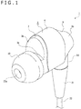
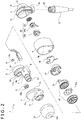
- the acoustic output apparatus 1 includes various necessary sections inside and outside a housing 2, and the housing 2 includes a front cover 3, a middle cover 4, and a rear cover 5 that are joined together from the front in sequence (refer to Figs. 1 to 3 ).
- the front cover 3 has a cover surface section 3a, a joint surface section 3b, and a holding tube section 3c.
- the cover surface section 3a is open rearward and approximately in the shape of a bowl.
- the joint surface section 3b protrudes rearward from a portion of the cover surface section 3a close to its periphery.
- the holding tube section 3c protrudes forward from the cover surface section 3a.
- the joint surface section 3b is formed approximately in the shape of an arc surface and protrudes rearward from the portion of the cover surface section 3a close to its periphery with the exception of a lower end portion.
- the middle cover 4 is formed in the shape of a tube having its axial direction extending longitudinally and has approximately the same outer size and shape as the cover section 3a.
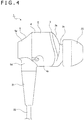
- the middle cover 4 has a vent hole 4a at its lower end portion (refer to Fig. 4 ).
- the rear cover 5 has a rear surface section 5a, a circumferential surface section 5b, a joint surface section 5c, an insertion tube section 5d, and an attachment tube section 5e (refer to Figs. 1 to 3 ).
- the rear surface section 5a is formed in an annular shape having its axial direction extending longitudinally. An inner space of the rear surface section 5a is formed as an opening 5f.
- the circumferential surface section 5b protrudes forward from a peripheral portion of the rear surface section 5a and is formed in such a shape that an outer shape thereof increases toward the front.
- the joint surface section 5c protrudes forward from a front end portion of the circumferential surface section 5b with the exception of the lower end portion.
- the insertion tube section 5d is formed in a cylindrical shape that protrudes downward from the lower end portion of the circumferential surface section 5b.
- the attachment tube section 5e is formed in a cylindrical shape that protrudes forward from the rear surface section 5a.
- the housing 2 is formed by joining a front end portion of the middle cover 4 with the joint surface section 3b of the front cover 3 such that the front end portion of the middle cover 4 is fitted onto the joint surface section 3b and by joining a rear end portion of the middle cover 4 with the joint surface section 5c of the rear cover 5 such that the rear end portion of the middle cover 4 is fitted onto the joint surface section 5c.
- the housing 2 has a bracket 6, and part of the bracket 6 protrudes forward from the holding tube section 3c.
- the bracket 6 has a first attachment section 7, a second attachment section 8, and a sound conduit 9.
- the first attachment section 7 has a base surface section 10 and a tube surface section 11.
- the base surface section 10 is disposed in a longitudinal orientation and approximately in the shape of a disk.
- the tube surface section 11 protrudes rearward from a peripheral portion of the base surface section 10.
- a sound input hole 10a, an adjustment hole 10b, and a first sound passage hole 10c are formed in this order from top in the base surface section 10 (refer to Fig. 5 ).
- the second attachment section 8 is located under the first attachment section 7, and an approximately rear half portion of the second attachment section 8 vertically is continuous with the first attachment section 7 (refer to Figs. 2 , 3 , and 5 ).
- a second sound passage hole 8a that penetrates a front half portion of the second attachment section 8 is formed in an upper surface section of the second attachment section 8.
- the sound conduit 9 has a sound tube section 9a and a partitioning plate 9b.
- the sound tube section 9a has its axial direction extending longitudinally and is approximately in a cylindrical shape.
- the partitioning plate 9b is located inside the sound tube section 9a.
- the sound conduit 9 protrudes forward from a lower end portion of the base surface section 10, and an approximately rear half portion of the sound conduit 9 is continuous with an approximately front half portion of the second attachment section 8.
- a first sound passage hole 10c of the base surface section 10 communicates with the second sound passage hole 8a of the second attachment section 8 in an inner space of the sound tube section 9a.
- the partitioning plate 9b is disposed in a vertical orientation and protrudes forward from a lower opening edge of the first sound passage hole 10c formed in the base surface section 10, and left and right side edges thereof are continuous with an inner surface of the sound tube section 9a, respectively. Therefore, part of the inner space of the sound conduit 9 is partitioned vertically by the partitioning plate 9b.
- the portion of the bracket 6 other than a front end portion of the sound conduit 9 is provided inside the housing 2, and the sound tube section 9a is held in a manner inserted in the holding tube section 3c of the front cover 3. A front end portion of the sound tube section 9a of the bracket 6 protrudes forward from the holding tube section 3c.
- An equalizer 12 is provided in a manner press-fitted into the front end portion of the sound tube section 9a.
- the equalizer 12 includes, for example, compressed urethane and primarily has a function to adjust, of the sounds that pass through the sound tube section 9a, the extent to which high frequencies are attenuated.
- a detection microphone 13, a register 14, and a speaker 15 are attached to the first attachment section 7 of the bracket 6.
- the detection microphone 13 functions as a feedback microphone for detecting noise near an ear and is attached at a position where the detection microphone 13 covers the sound input hole 10a on the front surface of the base surface section 10.
- the detection microphone 13 has an input vibrating plate 13a that is formed circular in outer shape and disposed approximately in a longitudinal orientation.
- the register 14 is formed, for example, in an annular shape and attached to a rear surface of the base surface section 10 with a center hole 14a located immediately behind the adjustment hole 10b.
- the register 14 primarily has a function to adjust, of the sounds output from the speaker 15, the sensitivity to low-frequency sounds.
- the center hole 14a of the register 14 is smaller in diameter than the adjustment hole 10b of the base surface section 10.
- the speaker 15 is attached to the bracket 6 with a front portion of the speaker 15 inserted in the first attachment section 7.
- the speaker 15 has an output vibrating plate 15a that is formed circular in outer shape and orientated approximately longitudinally.
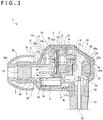
- the detection microphone 13 is attached to the front surface of the base surface section 10, the speaker 15 is attached to the rear surface of the base surface section 10, and the detection microphone 13 is located right in front of the speaker 15. Therefore, the detection microphone 13 as a whole is located to be opposed to the speaker 15.
- the input vibrating plate 13a of the detection microphone 13 and the output vibrating plate 15a of the speaker 15 are both oriented approximately longitudinally and disposed approximately in the same orientation.
- the speaker 15 can output sounds in a wide range of low to high frequencies.
- a distance between the detection microphone 13 and the speaker 15 is equal to or less than a radius of the detection microphone 13.
- the radius of the detection microphone 13 is 2 mm
- the distance between the detection microphone 13 and the speaker 15 is equal to or less than 1 mm.
- the detection microphone 13 (direction of a central axis S1) and the speaker 15 (direction of a central axis S2) both have their axes extending longitudinally, and the detection microphone 13 and the speaker 15 have their axes extending approximately in the same direction.
- a sound absorbing material 16 is attached to a rear surface of the speaker 15.
- the sound absorbing material 16 includes, for example, compressed urethane and primarily has a function to adjust, of the sounds output from the speaker 15, the sensitivity to medium and low frequencies.
- a disposition hole 17a is formed in the speaker cover 17.
- the speaker cover 17 is attached, from the rear, to the first attachment section 7 of the bracket 6 in such a manner as to cover the speaker 15 from the rear. With the speaker 15 covered by the speaker cover 17, the sound absorbing material 16 is disposed in the disposition hole 17a.
- a sound output device 18 is attached to the second attachment section 8 of the bracket 6.
- a microphone unit 20 is located in a region posterior to the speaker 15.
- the sound output device 18 is disposed in a manner inserted in the second attachment section 18 from the rear.
- the sound output device 18 functions, for example, as a tweeter and outputs high-frequency sounds that differ in frequency band from the sounds output from the speaker 15.
- a circuit board 19 is attached to a rear surface of the speaker cover 17.
- the circuit board 19 drives and controls the speaker 15 and the sound output device 18.
- the microphone unit 20 is attached to the attachment tube section 5e of the rear cover 5.
- the microphone unit 20 has a sensing microphone 20a, a microphone casing 20b, and a microphone sheet 20c.
- the sensing microphone 20a is covered by the microphone casing 20b from the front, and the microphone sheet 20c is attached to a rear surface of the sensing microphone 20a.
- the sensing microphone 20b is attached to the attachment tube section 5e inside the housing 2 to function as a feedforward microphone for detecting noise input from the opening 5f at a peripheral side position of the acoustic output apparatus 1.
- a bushing 21 is inserted into and attached to the insertion tube section 5d of the rear cover 5.
- a cable 22 is sheathed inside the bushing 21, and the cable 22 is connected to the circuit board 19, the detection microphone 13, and the sensing microphone 20a.
- a cap 23 is attached to the portion of the sound conduit 9 that protrudes forward from the holding tube section 3c of the front cover 3.
- the cap 23 includes a rubber material, etc. and is inserted into an ear hole when a user uses the acoustic output apparatus 1.
- a passage hole 23a that communicates with the inner space of the sound conduit 9 is formed in the cap 23.
- the sensing microphone 20a is disposed in the housing 2, and the detection microphone 13 and the sensing microphone 20a are located on the opposite sides to each other with the speaker 15 provided therebetween.
- the acoustic output apparatus 1 can be downsized through effective use of the space.
- bracket 6 is provided that has the sound conduit 9 to permit passage of sounds output from the speaker 15, and the speaker 15 and the detection microphone 13 are attached to the bracket 6.
- the speaker 15 and the detection microphone 13 are attached to the same member, thus eliminating the need for dedicated members for attaching the speaker 15 and the detection microphone 13, respectively, and ensuring further downsizing of the acoustic output apparatus 1 through reduced parts count.
- the sound output device 18 is attached to the bracket 6.
- the speaker 15, the detection microphone 13, and the sound output device 18 can all be attached to the same member, thus eliminating the need for dedicated members for attaching the speaker 15, the detection microphone 13, and the sound output device 18, respectively, and ensuring further downsizing of the acoustic output apparatus 1 through reduced parts count.
- the output sound passes through the sound conduit 9 from the first sound passage hole 10c of the base surface section 10. At this time, the sound passes above the partitioning plate 9a in the sound conduit 9 and reaches the user's eardrum via the passage hole 23a of the cap 23.
- a sound is also output from the sound output device 18, and the output sound passes through the sound conduit 9 from the second sound passage hole 8a of the second attachment section 8. At this time, the sound passes below the partitioning plate 9a in the sound conduit 9 and reaches the user's eardrum via the passage hole 23a of the cap 23.
- the sounds that are output from the speaker 15 and the sound output device 18 and pass through the sound conduit 9 are adjusted by the equalizer 12 in terms of the extent to which high frequencies are attenuated, thus allowing a sound whose high frequencies have properly been adjusted reaches the eardrum.
- the sound output from the sound output device 18 passes through the sound conduit 9.
- the sounds that are output from the speaker 15 and the sound output device 18 are both externally output through the sound conduit 9, thus eliminating the need for separate sound conduits through which the sound output from the speaker 15 and the sound output from the sound output device 18 pass, respectively, ensuring downsizing of the acoustic output apparatus 1 through reduced parts count, and contributing to reduced manufacturing cost.
- the output sound When a sound is output from the speaker 15, the output sound not only passes through the sound conduit 9 but also is input to the detection microphone 13 from the sound input hole 10a of the base surface section 10.
- the sound output from the speaker 15 passes through the center hole 14a of the register 14 via the adjustment hole 10b of the base surface section 10.
- the sensitivity to low frequencies is adjusted by the register 14.
- the sound that has passed through the center hole 14a of the register 14 is guided downward through the inner side of the front cover 3 and released externally from the vent hole 4a of the middle cover 4.
- the sound when a sound is output from the speaker 15, the sound is also output rearward, and the sensitivity to medium and low frequencies is adjusted by the sound absorbing material 16. At least part of the sound output rearward from the speaker 15 is guided downward and released externally from the vent hole 4a of the middle cover 4.
- a noise cancelling function is activated by the detection microphone 13 and the sensing microphone 20a.
- the noise cancelling function primarily detects noise in the sound passing through the sound conduit 9 with the detection microphone 13, detects noise in external sounds with the sensing microphone 20a, and then generates, with a noise cancelling circuit which is not illustrated, a noise cancelling signal that causes the user to perceive that each detected noise is minimal.
- the noise cancelling signal Since the noise cancelling signal is generated, the user perceives that the noise detected by the detection microphone 13 and the sensing microphone 20a, respectively, have been cancelled, thus hearing high-quality sounds with minimal noise.
- the acoustic output apparatus 1 has the detection microphone 13, the speaker 15, and the housing 2.
- the detection microphone 13 has the input vibrating plate 13a for detecting noise.
- the speaker 15 has the output vibrating plate 15a.
- the housing 2 accommodates at least the speaker 15 and the detection microphone 13 therein.
- the input vibrating plate 13a and the output vibrating plate 15a are disposed approximately in the same orientation.
- the detection microphone 13 and the speaker 15 have their axes extending approximately in the same direction.
- a sound is output from the speaker 15 while a sound is input to the detection microphone 13 with the speaker 15 and the detection microphone 13 having their axes extending approximately in the same direction, thus making it possible to bring the speaker 15 and the detection microphone 13 closer to each other.
- This makes it less likely for a phase lag to take place between the sound output from the speaker 15 and the sound input to the detection microphone 13, thus providing higher noise detection accuracy of the detection microphone 13 and contributing to an advanced noise cancelling function.
- the detection microphone 13 as a whole is located to be opposed to the speaker 15. As a result, the detection microphone 13 as a whole faces the speaker 15, thus contributing to an even more advanced noise cancelling function.
- the distance between the detection microphone 13 and the speaker 15 is equal to or less than the radius of the detection microphone 13. This makes it even more unlikely, since the distance between the detection microphone 13 and the speaker 15 is small, for a phase lag to take place between the sound output from the speaker 15 and the sound input to the detection microphone 13, thus contributing to an even more advanced noise cancelling function.
- the sensing microphone 20a is provided to detect noise input from the opening 5f of the housing 2. Therefore, noise is detected not only by the detection microphone 13 but also by the sensing microphone 20a, thus providing a higher noise reduction characteristic and contributing to improved sound quality of the acoustic output apparatus 1.
- the input vibrating plate 13a of the detection microphone 13 and the output vibrating plate 15a of the speaker 15 are disposed approximately in the same orientation as described above, thus providing higher noise detection accuracy of the detection microphone 13 and contributing to an improved noise cancelling function.
- the speaker 15 may diminish in output of sounds in a specific range such as high-frequency sounds.
- the sound output device 18 is provided in the acoustic output apparatus 1 to output a sound that differs in frequency band from the sound output from the speaker 15.
- the sound output device 18 outputs high-frequency sounds, for example, as described above.
- the speaker 15 may diminish in its capability to output high-frequency sounds, the user can hear excellent sounds in a wide range of low to high frequencies by high-frequency sounds output from the sound output device 18.
- the sound output device 18 is provided in the acoustic output apparatus 1 to output a sound that differs in frequency band from the sound output from the speaker 15. Therefore, even in the case where the speaker 15 diminishes in its capability to output sounds in some frequency bands, it is possible for the sound output device 18 to output the sounds which the speaker 15 has diminished in its capability to output, thus making it possible to output a wide range of sounds.
- the detection microphone 13 as a whole is located to be opposed to the speaker
- part of the detection microphone 13 may be located to be opposed to the speaker 15 in the acoustic output apparatus 1 (refer to Fig. 7 ).
- part of the detection microphone 13 is located to be opposed to the speaker 15 as described above, part of the detection microphone 13 faces the speaker 15, thus contributing to an excellent noise cancelling function.
- the detection microphone 13 as a whole may not be located to be opposed to the speaker 15 at all (refer to Fig. 8 ).
- the detection microphone 13 as a whole may not be located to be opposed to the speaker 15 at all.
- the present technology can have the following configurations.
Landscapes
- Engineering & Computer Science (AREA)
- Physics & Mathematics (AREA)
- Acoustics & Sound (AREA)
- Signal Processing (AREA)
- Manufacturing & Machinery (AREA)
- Health & Medical Sciences (AREA)
- Audiology, Speech & Language Pathology (AREA)
- General Health & Medical Sciences (AREA)
- Multimedia (AREA)
- Soundproofing, Sound Blocking, And Sound Damping (AREA)
- Circuit For Audible Band Transducer (AREA)
- Headphones And Earphones (AREA)
Applications Claiming Priority (2)
| Application Number | Priority Date | Filing Date | Title |
|---|---|---|---|
| JP2017157640 | 2017-08-17 | ||
| PCT/JP2018/026734 WO2019035304A1 (ja) | 2017-08-17 | 2018-07-17 | 音響出力装置 |
Publications (2)
| Publication Number | Publication Date |
|---|---|
| EP3672273A1 true EP3672273A1 (de) | 2020-06-24 |
| EP3672273A4 EP3672273A4 (de) | 2020-08-26 |
Family
ID=65362332
Family Applications (1)
| Application Number | Title | Priority Date | Filing Date |
|---|---|---|---|
| EP18847131.2A Ceased EP3672273A4 (de) | 2017-08-17 | 2018-07-17 | Schallausgabevorrichtung |
Country Status (5)
| Country | Link |
|---|---|
| US (1) | US11386880B2 (de) |
| EP (1) | EP3672273A4 (de) |
| JP (1) | JP7264052B2 (de) |
| CN (1) | CN111034216B (de) |
| WO (1) | WO2019035304A1 (de) |
Families Citing this family (6)
| Publication number | Priority date | Publication date | Assignee | Title |
|---|---|---|---|---|
| DE112020002986T5 (de) * | 2019-06-21 | 2022-03-10 | Sony Group Corporation | Tonausgabevorrichtung |
| JP7437244B2 (ja) * | 2020-06-17 | 2024-02-22 | ホシデン株式会社 | イヤホン |
| CN114666696B (zh) * | 2020-12-23 | 2023-06-06 | 华为技术有限公司 | 无线降噪耳机 |
| EP4102856B1 (de) | 2021-04-23 | 2026-02-11 | Samsung Electronics Co., Ltd. | Tragbares elektronisches gerät mit lautsprechern und mikrofon |
| KR102935346B1 (ko) * | 2021-08-06 | 2026-03-09 | 엘지전자 주식회사 | 휴대용 음향기기 |
| EP4529217A4 (de) * | 2023-01-30 | 2025-08-06 | Shenzhen Shokz Co Ltd | Bewegungsmodul und elektronische vorrichtung |
Family Cites Families (17)
| Publication number | Priority date | Publication date | Assignee | Title |
|---|---|---|---|---|
| JPH05333873A (ja) * | 1992-05-29 | 1993-12-17 | Sony Corp | 雑音低減装置 |
| US5692059A (en) | 1995-02-24 | 1997-11-25 | Kruger; Frederick M. | Two active element in-the-ear microphone system |
| US7466838B1 (en) * | 2003-12-10 | 2008-12-16 | William T. Moseley | Electroacoustic devices with noise-reducing capability |
| JP4850524B2 (ja) | 2006-01-27 | 2012-01-11 | ナップエンタープライズ株式会社 | 発振・エコーキャンセラーシステム |
| JP2009284097A (ja) | 2008-05-20 | 2009-12-03 | Toshiba Corp | カナル型イヤホンおよびその使用方法ならびに共鳴周波数算出装置 |
| JP4775438B2 (ja) | 2008-12-26 | 2011-09-21 | 日本ビクター株式会社 | ヘッドホン |
| US8553900B2 (en) | 2010-05-14 | 2013-10-08 | Creative Technology Ltd | Noise reduction circuit with monitoring functionality |
| WO2012042672A1 (ja) | 2010-10-01 | 2012-04-05 | フォスター電機株式会社 | ノイズキャンセルヘッドホン |
| TW201216725A (en) | 2010-10-06 | 2012-04-16 | Cotron Corp | Earphone |
| CN103460714B (zh) * | 2011-01-28 | 2016-08-31 | 海宝拉株式会社 | 耳内传声器及耳内传声器用电压控制装置 |
| US9058801B2 (en) * | 2012-09-09 | 2015-06-16 | Apple Inc. | Robust process for managing filter coefficients in adaptive noise canceling systems |
| US9055366B2 (en) * | 2013-01-22 | 2015-06-09 | Apple Inc. | Multi-driver earbud |
| CN105745119B (zh) * | 2013-11-19 | 2020-05-12 | 歌乐株式会社 | 头枕装置以及声音采集装置 |
| KR101693268B1 (ko) | 2015-04-10 | 2017-01-05 | 해보라 주식회사 | 이어셋 |
| US9613615B2 (en) | 2015-06-22 | 2017-04-04 | Sony Corporation | Noise cancellation system, headset and electronic device |
| JPWO2017126257A1 (ja) * | 2016-01-19 | 2018-10-04 | 富士フイルム株式会社 | 電気音響変換器 |
| JP6304336B2 (ja) | 2016-09-30 | 2018-04-04 | ソニー株式会社 | イヤホン装置 |
-
2018
- 2018-07-17 WO PCT/JP2018/026734 patent/WO2019035304A1/ja not_active Ceased
- 2018-07-17 JP JP2019536446A patent/JP7264052B2/ja active Active
- 2018-07-17 US US16/637,394 patent/US11386880B2/en active Active
- 2018-07-17 EP EP18847131.2A patent/EP3672273A4/de not_active Ceased
- 2018-07-17 CN CN201880051340.3A patent/CN111034216B/zh active Active
Also Published As
| Publication number | Publication date |
|---|---|
| JP7264052B2 (ja) | 2023-04-25 |
| US20200251086A1 (en) | 2020-08-06 |
| WO2019035304A1 (ja) | 2019-02-21 |
| JPWO2019035304A1 (ja) | 2020-07-27 |
| US11386880B2 (en) | 2022-07-12 |
| CN111034216B (zh) | 2022-07-01 |
| EP3672273A4 (de) | 2020-08-26 |
| CN111034216A (zh) | 2020-04-17 |
Similar Documents
| Publication | Publication Date | Title |
|---|---|---|
| US11386880B2 (en) | Acoustic output apparatus | |
| US20230156390A1 (en) | Acoustic output device | |
| EP3276980B1 (de) | Ohrhörer | |
| US8238596B2 (en) | In-ear headphones | |
| US9467762B2 (en) | Earphone device having sound guiding structures | |
| EP1895811B1 (de) | Mehrere Lautsprecher mit einem gemeinsamen Schallauslassrohr | |
| US8447061B2 (en) | Dual earphone using both bone conduction and air conduction | |
| EP1401237B1 (de) | Asymmetrisches Lautsprechergehäuse mit verbessertem niedrigen Frequenzgang | |
| US9613614B2 (en) | Noise-reducing headphone | |
| GB2461929A (en) | Earphones with compound drive units and level control | |
| WO2017075985A1 (zh) | 耳机 | |
| US10721549B2 (en) | Direct-radiating earphone drivers | |
| US7110563B2 (en) | Headphone | |
| CN106028196B (zh) | 一种耳机 | |
| JP2007110656A (ja) | 携帯端末用スピーカアクセサリ | |
| CA2822822C (en) | Stereo headset with noise suppression | |
| US11979707B1 (en) | System and method for an audio reproduction device | |
| EP4622292A1 (de) | Wandlerhaltemodul für kopfhörer | |
| HK40062934B (en) | Acoustic output device | |
| JP2019029900A (ja) | 首掛け型スピーカー装置 | |
| TW201626812A (zh) | 耳機 |
Legal Events
| Date | Code | Title | Description |
|---|---|---|---|
| STAA | Information on the status of an ep patent application or granted ep patent |
Free format text: STATUS: THE INTERNATIONAL PUBLICATION HAS BEEN MADE |
|
| PUAI | Public reference made under article 153(3) epc to a published international application that has entered the european phase |
Free format text: ORIGINAL CODE: 0009012 |
|
| STAA | Information on the status of an ep patent application or granted ep patent |
Free format text: STATUS: REQUEST FOR EXAMINATION WAS MADE |
|
| 17P | Request for examination filed |
Effective date: 20200317 |
|
| AK | Designated contracting states |
Kind code of ref document: A1 Designated state(s): AL AT BE BG CH CY CZ DE DK EE ES FI FR GB GR HR HU IE IS IT LI LT LU LV MC MK MT NL NO PL PT RO RS SE SI SK SM TR |
|
| AX | Request for extension of the european patent |
Extension state: BA ME |
|
| A4 | Supplementary search report drawn up and despatched |
Effective date: 20200723 |
|
| RIC1 | Information provided on ipc code assigned before grant |
Ipc: H04R 1/10 20060101AFI20200720BHEP Ipc: G10K 11/178 20060101ALI20200720BHEP |
|
| DAV | Request for validation of the european patent (deleted) | ||
| DAX | Request for extension of the european patent (deleted) | ||
| RAP3 | Party data changed (applicant data changed or rights of an application transferred) |
Owner name: SONY GROUP CORPORATION |
|
| STAA | Information on the status of an ep patent application or granted ep patent |
Free format text: STATUS: EXAMINATION IS IN PROGRESS |
|
| 17Q | First examination report despatched |
Effective date: 20220408 |
|
| REG | Reference to a national code |
Ref country code: DE Ref legal event code: R003 |
|
| STAA | Information on the status of an ep patent application or granted ep patent |
Free format text: STATUS: THE APPLICATION HAS BEEN REFUSED |
|
| 18R | Application refused |
Effective date: 20241126 |